etag 029 - sgp standard · ©eota etag 029_april 2013 page 3 1 scope of the etag the etag...
TRANSCRIPT

Established pursuant to Annex II of the Council Directive 89/106 of 21 December 1988 on theapproximation of laws, regulations and administrative provisions of Member States relating to construction products
(Construction Products Directive)
ETAG 029
GUIDELINE FOREUROPEAN TECHNICAL APPROVAL
of
METAL INJECTION ANCHORS FOR USE IN MASONRY
Edition April 2013
This Guideline for European Technical Approval is established and published in accordance with Article 11 ofthe Construction Products Directive as a basis for the preparation and issue of European Technical Approvals(ETA) in accordance with Article 9.1 of the Construction Products Directive.
European Technical Approvals are issued by Approval Bodies authorised and notified in accordance with Article10 of the Construction Products Directive. These bodies are organized in EOTA.
The European Technical Approval, according to the Construction Products Directive, is a favourable technicalassessment of the fitness for use of a construction product and the technical specification of the assessedproduct, serving as basis for the CE marking of this product when and where a harmonised standard accordingto the Directive is not or not yet available.
Due to technical innovation and the progress of the state of the art, Guidelines for technical approval might notreflect the latest developments and experiences gained in approval procedures. The reader of this Guideline istherefore advised to check with an EOTA member whether there are further provisions which have to be takeninto account in the use of the Guideline.
Copyright © 2013 EOTA
Note: The copyright refers to the English reference version established by EOTA. For publications inaccordance with Article 11.3 of the Construction Products Directive the national laws, regulations andadministrative provisions of the Member State concerned are applicable.
This edition replaces edition June 2010 of ETAG 029
__________________________________________________________________________________________________
EOTA Kunstlaan 40 Avenue des Arts B - 1040 BRUSSELS
European Organisation for Technical ApprovalsEuropäische Organisation für Technische ZulassungenOrganisation Européenne pour l’Agrément Technique

©EOTA ETAG 029_April 2013Page 2
Table of contents
1 SCOPE OF THE ETAG 31.1 Definition of the construction product 31.2 Intended use of the construction product 61.3 Assumed working life of the construction product 61.4 Terminology 7
1.4.1 Common terms relating to the Construction Products Directive 71.4.2 Specific terms used in this ETAG 7
1.5 Procedure in the case of a significant deviation from the ETAG 8
2 ASSESSMENT OF FITNESS FOR USE 92.1 Meaning of "fitness for use" 92.2 Elements of the assessment of fitness for use 92.3 Relationship of requirements to the product characteristics and methods of verification and
assessment 92.3.1 Relationship of requirements to the product characteristics 92.3.2 Use categories 11
2.4 Product characteristics which are relevant for the fitness for use relating to MechanicalResistance and Stability (ER 1) 112.4.1 Method of verification (General) 112.4.2 Method of assessing and judging (general) 17
2.5 Verification methods relating to Safety in Case of Fire (ER 2) 252.6 Verification methods relating to Hygiene, Health and the Environment (ER 3) 262.7 Verification methods relating to Durability 27
3 EVALUATION AND ATTESTATION OF CONFORMITY AND CE MARKING 293.1 System of attestation of conformity 293.2 Tasks and responsibilities of the manufacturer and notified body 29
3.2.1 Tasks of the manufacturer 293.2.2 Tasks for the notified body 30
3.3 CE marking and accompanying information 313.4 Marking of the product 31
4 ASSUMPTIONS UNDER WHICH THE FITNESS FOR THE INTENDED USE IS ASSESSED 324.1 Design method for anchorages 324.2 Packaging, transport, storage of the product 324.3 Installation of the product in the works 32
5 IDENTIFICATION OF THE CONSTRUCTION PRODUCT 33
6 FORMAT OF ETAS ISSUED ON THE BASIS OF THE ETAG 356.1 Definition of the anchor and its intended use 356.2 Characteristics of the anchor with regard to safety in use and methods of verification 356.3 Evaluation and attestation of conformity and CE marking 366.4 Assumptions under which the fitness of the product for the intended use was favourably
assessed 36
7 REFERENCE DOCUMENTS 36
Annex A Details of Tests
Annex B Recommendations for tests to be carried out on construction works
Annex C Design methods for anchorages

©EOTA ETAG 029_April 2013Page 3
1 SCOPE OF THE ETAG
The ETAG "METAL INJECTION ANCHORS FOR USE IN MASONRY“ covers the assessment of post-installed injection anchors placed into pre-drilled holes in masonry and anchored by bonding and mechanicalinterlock.
The injection anchors are intended to be used for anchorages for which requirements for mechanicalresistance and stability and safety in use in the sense of the Essential Requirements N° 1 (ER 1) and N° 4(ER 4) and, where applicable N° 2 (ER 2) and N° 3 (ER 3), of the CPD [1] shall be fulfilled; failure ofanchorages made with these products would cause an immediate risk to human life and/or possibly lead toconsiderable economic consequences. They are for fixing and/or supporting structural elements (whichcontribute to the stability of the works) or heavy units.
The fixture can be supported either statically determinate (one or two supports) or statically indeterminate(more than two supports).
The following annexes are full parts of the ETAG:Annex A: Details of testsAnnex B: Recommendations for tests to be carried out on construction works (informative)Annex C: Design methods for anchorages
1.1 Definition of the construction product
1.1.1 Types and operating principles
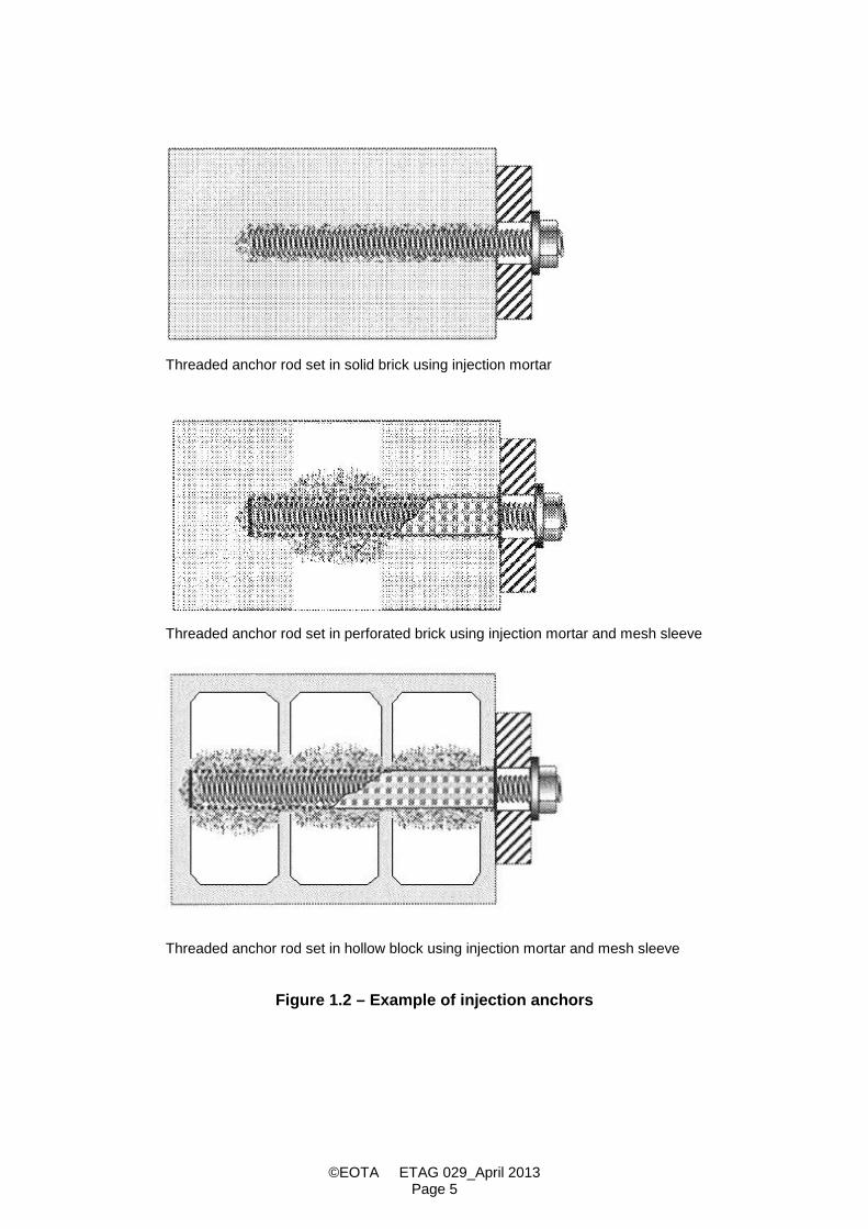
This ETAG applies to injection anchors consisting of a threaded rod, deformed reinforced bar, internalthreaded socket, or other shapes and the mortar, placed into drilled holes in masonry and anchored bybonding the metal part to the sides of the drilled hole by means of mortar and by mechanical interlock (seeFigure 1.1). For proper injection of the mortar, mesh sleeves made of metal or plastic are also covered in thisETAG (see Figure 1.2).
Injection anchors are supplied and used as a unit. However, if the metal parts are commercial standard partssupplied by another party than the approval holder (e.g. manufacturer of standard rods), specific conditionsaccording to 4.3 have to be fulfilled.
1.1.2 Materials
This ETAG applies to anchors in which all the metal parts directly anchored in the masonry and designed totransmit the applied loads are made either of carbon steel, stainless steel or malleable cast iron.
The bonding material may be manufactured from cementitious mortar, synthetic mortar or a mixture of thetwo including fillers and/or additives.
1.1.3 Dimensions
This ETAG applies to anchors with a minimum thread size of 6 mm (M6).The minimum anchorage depth of the anchor min hef shall be 50 mm.The maximum anchorage depth shall be max hef = hmin -30 mm.
This ETAG applies to applications where the minimum thickness of the masonry members in which injectionanchors are installed is at least hmin = 80 mm.
Anchors with internal thread are covered only if they have a thread length of at least d + 5 mm after takingaccount of possible tolerances.

©EOTA ETAG 029_April 2013Page 4
Figure 1.1 – Example of injection anchors
1. sieve sleeve2. threaded rod with
washer andhexagon nut
3. injection cartridge
©EOTA ETAG 029_April 2013Page 5
Threaded anchor rod set in solid brick using injection mortar
Threaded anchor rod set in perforated brick using injection mortar and mesh sleeve
Threaded anchor rod set in hollow block using injection mortar and mesh sleeve
Figure 1.2 – Example of injection anchors

©EOTA ETAG 029_April 2013Page 6
1.1.4 Base material (masonry)
This ETAG applies to the use of injection anchors in masonry units of clay, calcium silicate, normal weightconcrete and lightweight aggregate concrete (solid and hollow or perforated format blocks), autoclavedaerated concrete or other similar materials. As far as the specification of the different masonry units isconcerned, EN 771-1 to 5:2011 [2] may be taken as reference. The design and construction of masonrystructures in which the injection anchors are to be anchored shall be in accordance withEN 1996-1-1:2005 + AC:2009 [6] and the relevant national regulations.
Attention is drawn to the fact that the standards for masonry are not very restrictive with regard to details ofunits (e.g. type, dimensions and location of hollows, number and thickness of webs). Anchor resistance andload displacement behaviour, however, decisively depend on these influencing factors.
Usually solid masonry units do not have any holes or cavities other than those inherent in the material.However, solid units may have a vertical perforation or grip holes of up to 15 % of the cross section or frogsup to 20 % based on the volume of the brick. Therefore testing in solid material covers units with verticalperforation or grip holes of up to 15 % of the cross section or frogs up to 20 % based on the volume of thebrick.
Masonry units consisting of hollow or perforated units have a certain volume percentage of voids which passthrough the masonry unit. For the assessment of injection anchors anchored in hollow or perforated units ithas also to be assumed that the anchor may be situated in solid material (e.g. joints, solid part of unit withoutholes) so that also tests in solid material may be required.
1.2 Intended use of the construction product
The injection anchors are intended to be used for anchorages for which requirements for mechanicalresistance and stability and safety in use in the sense of the Essential Requirements N° 1 (ER1) and N° 4(ER4) and, where applicable N° 2 (ER 2) and N° 3 (ER 3), of the CPD shall be fulfilled; failure of anchoragesmade with these products would cause an immediate risk to human life and/or possibly lead to considerableeconomic consequences. They are for fixing and/or supporting structural elements (which contribute to thestability of the works) or heavy units.
This ETAG applies only to anchors subject to static or quasi-static actions in tension, shear or combinedtension and shear or bending. The anchors may be used in areas with very low seismicity according toEN 1998-1:2004 + AC:2009 [15].
This ETAG covers applications only where the masonry members in which the anchors are embedded aresubject to static or quasi-static actions.
1.3 Assumed working life of the construction product
The provisions and the verification and assessment methods included or referred to in this ETAG have beenwritten based upon the assumed working life of the injection anchors for the intended use of 50 years wheninstalled in the works, provided that the injection anchors are subject to appropriate installation and use (see4.3). These provisions are based upon the current state of the art and the available knowledge andexperience.
"Assumed working life" means that, when an assessment following the ETAG provisions is made, and whenthis working life has elapsed, the real working life may be, in normal use conditions, considerably longerwithout major degradation affecting the Essential Requirements.
The indications of durability (linked to the working life) of the construction product cannot be interpreted as aguarantee given by the product manufacturer or his representative or the Approval Body issuing the ETA, butare regarded only as a means for choosing the appropriate products in relation to the expected economicallyreasonable working life of the works (see 5.2.2 of the Interpretative Documents).

©EOTA ETAG 029_April 2013Page 7
1.4 Terminology
1.4.1 Common terms relating to the Construction Products Directive
For the meaning of these terms see EOTA document "Common terms used in Guidelines for EuropeanTechnical Approval" published on the EOTA website.
1.4.2 Specific terms used in this ETAG
1.4.2.1 GeneralAnchor = a manufactured, assembled component including bonding materials for achieving
anchorage between the base material (masonry) and the fixture.Anchor group = several anchors (working together)Fixture = component to be fixed to the masonryAnchorage = an assembly comprising base material (masonry), anchor or anchor group and
component fixed to the masonry.
1.4.2.2 AnchorsThe notations and symbols frequently used in this Guideline are given below. Further particular notation andsymbols are given in the text.b = width of the member of the base materialc = edge distance towards the free edge of the brick
(edge of the wall or vertical joint not to be filled with mortar)ccr = edge distance for ensuring the transmission of the characteristic resistance of a single
injection anchorcmin = minimum allowable edge distanced = anchor bolt/thread diameterd0 = drill hole diameterdcut = cutting diameter of drill bitdcut,m = medium cutting diameter of drill bitdf = diameter of clearance hole in the fixturednom = outside diameter of anchorh = thickness of masonry member (wall)hmin = minimum thickness of masonry memberh0 = depth of cylindrical drill hole at shoulderh1 = depth of drilled hole to deepest pointhef = effective anchorage depthhnom = overall anchor embedment depth in the masonrylunit = length of the masonry unithunit = height of the masonry units = spacing of the injection anchorscr,N = spacing for ensuring the transmission of the characteristic resistance of a single
injection anchorscr,II = scr II horizontal jointscr,┴ = scr ┴ horizontal jointsmin = minimum allowable spacingT = torque momentTinst = installation torque moment recommended by the manufacturerTu = maximum torque moment during failuretfix = thickness of fixturet = thickness of outer web of the brick
1.4.2.3 Base materials (masonry) and metal parts of anchor = bulk density of masonry unitfb = normalised mean compressive strength of masonry unitfb,test = mean compressive strength of the test masonry unit at the time of testingfy,test = steel tensile yield strength in the testfyk = nominal characteristic steel yield strengthfu,test = steel ultimate tensile strength in the testfuk = nominal characteristic steel ultimate strength

©EOTA ETAG 029_April 2013Page 8
1.4.2.4 Loads/forcesF = force in generalN = normal force (+N = tension force)V = shear forceM = momentNRk,VRk = characteristic anchor resistance (5 %-fractile of results) under tension
and shear force, respectivelyhSdN ( h
SdV ) = design value of tensile load (shear load) acting on the most stressed anchor of ananchor group
1.4.2.5 TeststRuF = ultimate load in a testt
mRu,F = mean ultimate load in a test seriestRkF = 5 %-fractile of the ultimate load in a test series
n = number of tests of a test seriesv = coefficient of variation(N, V) = displacement (movement) of the anchor at the masonry surface
relative to the masonry surface in direction of the load (tension, shear) outside thefailure area. The displacement includes the steel and masonry deformations and apossible anchor slip.
= ratio of test value / reference value, for instance
1.4.2.6 Temperature termsService temperature range: Range of ambient temperatures after installation and during the lifetime of theanchorage.
Short term temperature: Temperatures within the service temperature range which vary over short intervals,e.g. day/night cycles and freeze/thaw cycles.
Maximum short term temperature: Upper limit of the service temperature range.
Long term temperature: Temperature within the service temperature range, which will be approximatelyconstant over significant periods of time. Long term temperatures will include constant or near constanttemperatures, such as those experienced in cold stores or next to heating installations.
Maximum long term temperature: Specified by the manufacturer within the range of 0,6 times to 1,0 times themaximum short term temperature.
Normal ambient temperature: Temperature 21 °C 3 °C (for test conditions only)
Open time: The maximum time from end of mixing to when the insertion of the anchor into the bondingmaterial shall be completed.
Installation ambient temperature range: The environmental temperature range of the base material allowedby the manufacturer for installation.
Anchor component installation temperature range: The temperature range of the bonding material andembedded part immediately prior to installation.
Curing time: The minimum time from the end of mixing to the time when the anchor may be torqued orloaded (whichever is longer). The curing time depends on the ambient temperature.
1.5 Procedure in the case of a significant deviation from the ETAG
The provisions of this ETAG apply to the preparation and issue of European Technical Approvals inaccordance with Article 9.(1) of the CPD and Section 3.1 of the Common Procedural Rules.
In cases in which a certain provision of this ETAG is not or not fully applicable or a particular aspect of aproduct and/or intended use to be assessed is not or not sufficiently covered by the methods and criteria ofthe ETAG, the procedure of Article 9.(2) of the CPD and Section 3.2 of the Common Procedural Rules mayapply with regard to the deviation or aspect concerned.

©EOTA ETAG 029_April 2013Page 9
2 ASSESSMENT OF FITNESS FOR USE
2.1 Meaning of "fitness for use"
"Fitness for (the intended) use" of a construction product means that the product has such characteristics that
the works in which it is to be incorporated can, if properly designed and built,
1. satisfy the Essential Requirements when and where such works are subject to regulationscontaining such requirements (CPD Article 2.(1)) and
2. be fit for their intended use, account being taken of economy, and in this connection satisfy theEssential Requirements for an economically reasonable working life, if normally maintained (seeCPD Annex I, sentence 1 and 2).
2.2 Elements of the assessment of fitness for use
The assessment of the fitness of a construction product for its intended use includes: the identification of the characteristics of the product which are relevant to its fitness for use (in
the following referred to as "regulatory characteristics"); the establishment of methods for the verification and assessment of the regulatory product
characteristics and the expression of the respective product performances; the identification of such regulatory characteristics to which the option "No Performance
Determined" applies for the reason that in one or more Member States they are not relevant forthe fulfilment of the requirements applicable to the works;
the identification of such regulatory characteristics for which limit values (threshold values) haveto be respected for technical reasons.
2.3 Relationship of requirements to the product characteristics and methods of verification andassessment
2.3.1 Relationship of requirements to the product characteristics
The product characteristics, methods of verification and assessment criteria which are relevant for the fitnessof injection anchors for the intended use referred to in 1.2 are given in Table 2.1.

©EOTA ETAG 029_April 2013Page 10
Table 2.1 – Product characteristics and methods of verification and assessment
No Product characteristic Option "NoPerformanceDetermined"
Method ofverification
andassessment
Expression of product performance
(1) (2) (3) (4) (5)
Essential Requirement 1: Mechanical resistance and stability
1 Suitability under normal siteconditions:Requirements for an acceptableload/displacement behaviour,a certain ultimate load,a certain limited scatter
No 2.4.1 and
2.4.2
Influence factors on the loadbearing behaviour of the anchor inaccordance with the criteria of2.4.2
2 Admissible service conditions:- load bearing behaviour of the
anchor for tension/shear/combined tension and shear/bending
- Required spacing and edgedistance of the anchor
- Minimum spacing and minimumedge distance of the anchor
- Displacement for serviceabilitylimit state of the anchor
No 2.4.1 and
2.4.2
2.4.2.2.3- Characteristic resistance for
tension/shear/ combined tensionand shear/ bending
- Characteristic spacing and edgedistance of the anchor
- Minimum spacing and minimumedge distance of the anchor
- Displacement for serviceabilitylimit state of the anchor
Essential Requirement 2: Safety in case of fire
3 Reaction to fire Yes (Class F) 2.5.1 Anchorages satisfy requirementsfor Class A1 (see 2.5.1)
4 Resistance to fire No 2.5.2 Evaluation of the couple anchor-concrete (anchorages) concerningresistance to fire by tests orcalculations
Essential Requirement 3: Hygiene, health and environment
5 Content and/or release ofdangerous substances
Yes 2.6 See the relevant chapter 2)
Essential Requirement 4: Safety in use
6 The same criteria are valid as for Essential Requirement 1
Essential Requirement 5: Protection against noise
None
Essential Requirement 6: Energy economy and heat retention
None
General aspects relating to fitness for use 1)
7 Suitability against environmentalconditions
No 2.7.1 Resistance against environmentalconditions
1) Aspects of durability and economy of the works (see CPD, Annex 1, sentences 1 and 2) which are not dealt withunder Essential Requirements 1 to 6. Such aspects are also referred to as “serviceability”.
2) NPD option regarding ER3: For the meaning of the NPD option regarding ER3, see EOTA TR 034 "GeneralChecklist for ETAGs/CUAPs/ETAs - Content and/or release of dangerous substances in products/kits” [18]

©EOTA ETAG 029_April 2013Page 11
2.3.2 Use categories
The Guideline applies to anchorages in respect of the following use categories:
2.3.2.1 Use categories in respect of the base material:
Use category b: Metal injection anchors for use in solid1) masonryUse category c: Metal injection anchors for use in hollow or perforated masonryUse category d: Metal injection anchors for use in autoclaved aerated concrete masonry
Each use category shall be given in the approval separately.
1) Covers also units with vertical perforation or grip holes of up to 15 % cross section or frogs up to 20 %based on the volume of the brick
2.3.2.2 Use categories in respect of installation and use:
Category d/d - Installation and use in structures subject to dry, internal conditions,Category w/d - Installation in dry or wet substrate and use in structures subject to dry, internal conditions,Category w/w - Installation and use in structures subject to dry or wet environmental conditions.
Each use category shall be given in the approval separately.
2.3.2.3 Use categories in respect of the service temperature range:The functioning of an injection anchor, including its ability to continue to withstand its design load with anappropriate safety factor and to limit displacements, shall not be adversely affected by temperatures in thebase material near to the surface within a temperature range to be specified by the manufacturer which maybe either:
(Ta) - 40 °C to + 40 °C (max short term temperature + 40 °C and max long term temperature + 24 °C)(Tb) - 40 °C to + 80 °C (max short term temperature + 80 °C and max long term temperature + 50 °C)(Tc) on manufacturer's request with - 40 °C to T1 (short term: T1 > + 40 °C, long term: 0,6 T1 to 1,0 T1)
Injection anchors are not affected by service temperatures down to - 40 °C. If there is no experience forunknown bonding materials on their performance at - 40 °C then normal pull-out tests at – 40 °C will berequired.
The performance shall not be adversely affected by short term temperatures within the service temperaturerange or by long term temperatures up to the maximum long term temperature.
Performance at the maximum long term temperature and maximum short term temperature is checked bytests described in 2.4.1.1.2
2.4 Product characteristics which are relevant for the fitness for use relating to MechanicalResistance and Stability (ER 1)
2.4.1 Method of verification (General)
The tests involved in the assessment of injection anchors fall into 3 categories:
(1) Tests for confirming their suitability (see 2.4.1.1)(2) Tests for evaluating the admissible service conditions (see 2.4.1.2)(3) Tests for checking durability (see 2.7.1)
The details of tests are given in Annex A.
It is assumed that for each injection anchor size there is only one anchorage depth. If the injection anchorsare intended to be installed with two or more anchorage depths the tests have to be carried out at eachdepths.

©EOTA ETAG 029_April 2013Page 12
2.4.1.1 Tests for suitabilityThe purpose of the suitability tests is to establish whether an anchor is capable of safe, effective behaviour inservice including consideration of adverse conditions both during site installation and in service.
The types of suitability tests, test conditions, the number of required tests and the criteria applied to theresults shall be taken in accordance with Table 2.4.2. Detailed information about special tests is given in thechapters after the table.
Table 2.4.1 – Base material for suitability tests for injection anchors to be used in masonry
Purpose of test Base material for use categoriesb and c
Base material foruse category d
Solid clay Solid calciumsilicate
Autoclaved aeratedconcrete
1a1b Installation safety x x x
2a Functioning, effect of increased temperature x x x2b2c Functioning, effect of installation temperature (1) x
3 Functioning under repeated loads (1) x
4a Functioning under sustained loads(normal temperature) (1) x
4b Functioning under sustained loads(max. long term temp.) (1) x
5 Maximum torque moment Tests in all types of bricks as applied for6 Functioning under freeze/thaw condition (1) (2)7 Checking durability of the bonding material C20/25
Notes to Table 2.4.1
(1) Tests in solid clay masonry units or solid calcium masonry units, resulting from reference tests accordingto Table 2.4.4, line 1 (the maximum resistance is decisive). If the same injection system is alreadyassessed in accordance with ETAG 001-5: Edition 2002. Amendment 2012 [17], the results of therelevant suitability tests (reduction factors) can also be used for anchors for use in masonry.
(2) Tests in freeze-thaw resistant base material (see also 2.4.1.1.6).

©EOTA ETAG 029_April 2013Page 13
Table 2.4.2 – Suitability tests for injection anchors to be used in masonry
Purpose of test Ambientbase
materialTempe-rature
Minimum number oftests for anchor size
(2)
Criteria Test proceduresuitability testsdescribed in
s i m i l load/dis.behaviour
req. (1)
1Installation in(a) dry substrate
normal 5 - 5 - 5 2.4.2 (c) ≥ 0,8 2.4.1.1.1a)
(b) wet substrate (3) normal 5 - 5 - 5 2.4.2 (c) ≥ 0,8 2.4.1.1.1b)2 Functioning, effect of
temperature (4)(a) increased temperature
+50 °C(5)+80 °C(5)
55
2.4.2 (c)≥ 1,0
≥ 0,8 (6)
2.4.1.1.2
(b) low temperature (4) 5 ≥ 1,0(c) minimum curing time normal 5 ≥ 0,9More detailed description analogous Section 2.4.1.1.2.
3 Functioning underrepeated loads
normal - - 5 - - 2.4.2 (c) ≥ 1,0 2.4.1.1.3
4 Functioning undersustained loads
normal+ 50 °C(5)
- - 5 - - 2.4.2 (c) ≥ 0,9 2.4.1.1.4
5 Maximum torque moment normal 5 5 5 5 5 2.4.1.1.56 Functioning under
freeze/thaw condition (7)normal - - 5 - - 2.4.2 (c) ≥ 0,9 2.4.1.1.6
7 Checking durability of thebonding material
see 2.7.1.2
Notes to Table 2.4.2
(1) If requirement is not met, corresponding provisions are given in 2.4.2.1
(2) Anchor size: s = smallest; i = intermediate; m = medium; l = largestIf installation with sieve sleeve in solid bricks (or solid parts of bricks) is allowed in the ETA, the testsshall be done with sieve sleeve otherwise the tests shall be performed without sieve sleeve.
(3) This test is not required for use category d/d (dry)
(4) Minimum installation temperature as specified by the manufacturer; normally 0 °C to + 5 °C
(5) For temperature range (Tb), for other temperature ranges see 2.3.2.3
(6) Reference values from the tests with maximum long term temperature +50 °C for temperature range(Tb), for other temperature ranges see 2.3.2.3
(7) For use category w/w only
2.4.1.1.1 Installation in dry or wet substrate
(a) Installation in dry substrateConfined tension tests in dry solid masonry according to Annex A, A.5.4 a). These tests have to be performedfor all use categories.
(b) Installation in wet substrateConfined tension tests in wet solid masonry according to Annex A, A.5.4 b). These tests may be omitted foruse category d/d.
2.4.1.1.2 Influence of temperature on characteristic resistances
(a) Effect of increased temperatureThe confined tension tests shall be carried out according to Annex A, A.5.5 a) for the different temperatureranges given in 2.3.2.3.(b) Effect of low installation temperature
©EOTA ETAG 029_April 2013Page 14
The confined tension tests shall be carried out at the end of the curing time while maintaining the temperatureof the test member at the specified lowest installation temperature 2 K. Details of the tests are described inAnnex A, A.5.5 b).
(c) Minimum curing time at normal ambient temperaturePerform tension tests according to Annex A, A.5.5 c) at normal ambient temperature at the correspondingminimum curing time specified by the manufacturer.
2.4.1.1.3 Repeated loadingThe injection anchor is subjected to 1 x 10⁵ load cycles with a maximum frequency of approximately 6 Hz.After completion of the load cycles the anchor shall be unloaded, the displacement measured and a tensiontest performed according to Annex A. Details of the tests are described in Annex A, 5.6.
2.4.1.1.4 Sustained loadingThe test is performed at normal temperature (T = + 21 °C ± 3 °C) for temperature range (Ta), (Tb) and (Tc)and at maximum long term temperature for temperature range (Tb) and (Tc) [T = + 50 °C at minimum fortemperature range (Tb)].
The anchor shall be installed at normal temperature and subjected to a tension (sustained) load. Aftercompletion of the sustained load test the anchor shall be unloaded, the displacement measured andimmediately after unloading a tension test performed. Details of the tests are described in Annex A, A.5.7.
2.4.1.1.5 Maximum torque momentThe torque moment shall be measured with a calibrated torque moment transducer. The torque momentshall be increased until failure of the injection anchor. Details of the tests are described in Annex A, A.5.8.
2.4.1.1.6 Functioning under freeze/thaw conditionsIn general the tests are carried out for injection anchors with a service condition in wet substrate only. Thetests are performed in freeze-thaw resistant base material. The tests may also be carried out in freeze-thawresistant concrete C50/60; in this case the corresponding reference tests are required in concrete undernormal conditions as well.
The displacements shall be measured during the temperature cycles.
After completion of 50 cycles, carry out a tension test at normal ambient temperature. Details of the tests aredescribed in Annex A, A.5.9.
2.4.1.2 Tests for evaluating the admissible service conditionsFor determination of the admissible service conditions, the tests given in Table 2.4.3 shall be carried out.
If existing information is available from the manufacturer and the corresponding test report contains allrelevant data, then the Approval Body may reduce the number of tests for admissible service conditions,making use of this existing information. However, it will be considered in the assessment only if the resultsare consistent with comparable test results available to the Approval Body.
All tests for determination of admissible service conditions shall be carried out according to Annex A in thebase material for which the injection anchor is intended to be used.
The minimum edge distance cmin and minimum spacing smin shall be given by the manufacturer and shall beconfirmed by the corresponding tests.
The determined characteristic resistances for the approval are valid only for the bricks and blocks which areused in the tests regarding base material (masonry or aerated concrete), size of units, compressive strengthand configuration of the voids. Therefore the following information has to be given in the test report and in theapproval:
Base material, size of units, normalised compressive strength; volume of all holes (% of the gross volume);volume of any hole (% of the gross volume); minimum thickness in and around holes (web and shell);combined thickness of webs and shells (% of the overall width); appropriation to a group of Table 3.1 ofEN 1996-1-1:2005 + AC:2009 [6].
©EOTA ETAG 029_April 2013Page 15
As far as the specification of the different masonry units is concerned, EN 771-1 to 5:2011 [2] may be takenas reference.
In hollow or perforated masonry, anchorages in the end side of a wall (reveal) are covered only, if the testsinclude this setting position. Therefore this information has to be given in the test reports and in the approval.
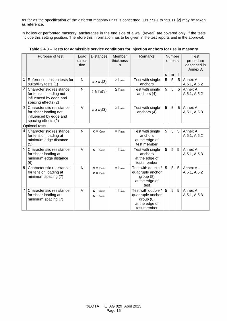
Table 2.4.3 – Tests for admissible service conditions for injection anchors for use in masonry
Purpose of test Loaddirec-tion
Distances Memberthickness
h
Remarks Numberof tests
Testprocedure
described inAnnex A
s m l1 Reference tension tests for
suitability tests (1)N c ≥ ccr(3) ≥ hmin Test with single
anchors5 5 5 Annex A,
A.5.1, A.5.22 Characteristic resistance
for tension loading notinfluenced by edge andspacing effects (2)
N c ≥ ccr(3) ≥ hmin Test with singleanchors (4)
5 5 5 Annex A,A.5.1, A.5.2
3 Characteristic resistancefor shear loading notinfluenced by edge andspacing effects (2)
V c ≥ ccr(3) ≥ hmin Test with singleanchors (4)
5 5 5 Annex A,A.5.1, A.5.3
Optional tests4 Characteristic resistance
for tension loading atminimum edge distance(5)
N c = cmin = hmin Test with singleanchors
at the edge oftest member
5 5 5 Annex A,A.5.1, A.5.2
5 Characteristic resistancefor shear loading atminimum edge distance(6)
V c = cmin = hmin Test with singleanchors
at the edge oftest member
5 5 5 Annex A,A.5.1, A.5.3
6 Characteristic resistancefor tension loading atminimum spacing (7)
N s = smin
c = cmin
= hmin Test with double /quadruple anchor
group (8)at the edge of
test
5 5 5 Annex A,A.5.1, A.5.2
7 Characteristic resistancefor shear loading atminimum spacing (7)
V s = smin
c = cmin
= hmin Test with double /quadruple anchor
group (8)at the edge oftest member
5 5 5 Annex A,A.5.1, A.5.3
©EOTA ETAG 029_April 2013Page 16
Notes to Table 2.4.3
(1) Reference tension tests for determination of the results of the suitability tests. They have to becarried out on the same masonry units regarding base material, size of units and compressivestrength as used for the corresponding suitability tests. They have to be performed with the sameanchor configuration (e.g. size, sieve sleeve) as used for the corresponding suitability tests.
If the results of the reference tests are smaller than the results of the tests for characteristicresistance, the reference tests shall be considered for evaluating of the characteristic resistance.
(2) The tests shall be carried out at the most unfavourable setting position in the brick of hollow orperforated masonry, which give the lowest characteristic resistance of the anchor. For example, ifhollow brick consists of thick webs or shells, the anchor shall be tested in the hole as well as in themassive parts of the brick.
For the intended use in plastered masonry (the joints are not visible) additional tests in joints not filledwith mortar are necessary, if the drilling diameter is smaller than 15 mm. If such products are nottested and assessed, the relevant ETA shall allow the use only if the setting position in a joint onlycan be excluded (e.g. removal of the plaster around the installation position).
(3) For characteristic edge distances the following distances may be used (standard values):Anchorages in solid masonry and AAC: ccr = 1,5 hefAnchorages in hollow or perforated masonry: ccr = max (100 mm; 6 d0)
If the manufacturer accepts these standard values ccr as the minimum value cmin, tests on the freeedge can be omitted.
(4) For determination of a group of two or four injection anchors the following spacing may be used(standard values):
Anchorages in solid masonry and AAC: scr = 3,0 hefAnchorages in hollow or perforated masonry: scr,II = lunit (scr II horizontal joint)
scr,┴ = hunit (scr ┴ horizontal joint)
If the manufacturer accepts these standard values scr as the minimum value smin, tests with anchorgroups can be omitted.
(5) Tension tests with single anchors near the free edge of a wall to determine the characteristicresistance depending on the minimum edge distance cmin. These tests can be omitted, if for cmin thevalue ccr is accepted.
(6) Shear tests with single anchors in direction to the free edge of a wall to determine the characteristicresistance depending on the minimum edge distance cmin. This test can be omitted, if the resistancecalculated according to Annex C, C.5.2.2.5 is accepted.
(7) The spacing smin may also be evaluated by appropriate tests with an anchor group of two anchorswith smin,II and/or smin,┴ and/or with an anchor group of four anchors with smin,II and/or smin,┴.smin shall be given in the approval (spacing of a group of anchors in the tests)
The spacing smin shall be greater than the following values:
Anchorages in solid masonry and AAC: smin max (50 mm; 3 d0)Anchorages in hollow or perforated masonry: smin max (75 mm; 5 d0)This test may be omitted if for smin the value scr is accepted.
(8) Double and/or quadruple anchor group depend on the application of the manufacturer. The testedconfiguration will be given in the ETA.

©EOTA ETAG 029_April 2013Page 17
2.4.2 Method of assessing and judging (general)
This sub-clause details the assessing and judging of the injection anchors related to the intended use, usingthe verification methods of 2.4.1.
(a) 5%-fractile of the ultimate loads
The 5%-fractile of the ultimate loads measured in a test series is to be calculated according to statisticalprocedures for a confidence level of 90 %. If a precise verification does not take place, a log normaldistribution and an unknown standard deviation of the population shall be assumed.
F5% = F (1 - ks . v) (2.4.1)
e.g.: n = 5 tests: ks = 3,40n = 10 tests: ks = 2,57
(b) Conversion of ultimate loads to take account of masonry and steel strength
Masonry unit strength:
In some cases it can be necessary to convert the results of a test series to correlate with a unit strengthdifferent from that of the test unit. In the case of unit failure, this conversion shall be carried out according toEquation (2.4.2)
FRu (fb) = tRuF .
test,b
bf
f (2.4.2)
with:FRu (fb) = failure load at unit compressive strength fb = 0,5 for masonry units of clay or concrete and solid unit of calcium silicate = 0,75 for masonry units of perforated calcium silicate (in this connection the range in
the unit strength in the tests is limited to 100 % of the nominal strength of the unitfor the characteristic resistance)
fb,test = mean compressive strength of the masonry unit at the time of testing with fb,test > fb(if fb,test < fb, then fb,test or the next smaller strength class fb shall be given in theapproval)
In the case of pull-out failure the influence of the unit strength on the failure load shall be established. In theabsence of better information, Equation (2.4.2) may be used as an approximation.
Autoclaved aerated concrete units strength:
General:The tests results shall be converted as far as compressive strength and dry density are concerned.
Compressive strength:For AAC blocks the characteristic compressive strength shall be determined from the declared value ofcompressive strength according to EN 771-4: using the factor of 0,9.
fck = 0,9 fc,decl
Dry density:As reference values of dry density the following minimum values of dry density shall be used for low and highstrength AAC for conversion of the test results:
low strength AAC: min = 350 kg/m3
high strength AAC: min = 650 kg/m3
Conversion of test results:The test results obtained for low and high strength AAC shall be converted using the following Equation:
test,c4/3
test
ck4/3
mintRu
tRu f
fFF K
(kN) (2.4.3)
From the above, the 5 %-fractile for the ultimate load shall be derived.

©EOTA ETAG 029_April 2013Page 18
Characteristic failure load (ultimate load) of the different strength of AAC:For the strength between low and high strength AAC the characteristic failure loads shall be determined bylinear interpolation of the converted test results.
Steel strength:
In case of steel failure the failure load shall be converted to the nominal steel strength by Equation (2.4.4)
FRu fuk = tRuF .
testu,
ukff (2.4.4)
with:FRu (fuk) = failure load at nominal characteristic steel ultimate strength
(c) In all tests the following criteria shall be met:
(1) In all tension tests the load-displacement curves shall show a steady increase (see Figure 2.4);uncontrolled slip of injection anchors is not allowed.
Solid masonry units (bond between steel element, injection mortar and masonry)
Uncontrolled slip occurs when the mortar with the embedded part is pulled out of the drilled hole(because then the load displacement behaviour depends significantly on irregularities of the drilled hole).The corresponding load when uncontrolled slip starts is called load at loss of adhesion Nu,adh. For therequirement on the load-displacement curves with respect to uncontrolled slip the following evaluationshall be done:
Nu,adh shall be evaluated for every test from the measured load displacement curve. In general the loadat loss of adhesion is characterised by a significant change of stiffness, see Figure 2.4 a. If the changein stiffness at a defined load is not so obvious e.g. the stiffness is smoothly decreasing, than the load atloss of adhesion shall be evaluated as follows:
1) Compute the tangent to the load-displacement curve at a load 0,3 Nu (Nu = peak load in test). Ingeneral the tangent stiffness can be taken as the secant stiffness between the points 0/0 and0,3 Nu/0,3 (0,3 = displacement at N = 0,3 Nu).
2) Divide the tangent stiffness by a factor of 1,5.3) Draw a line through the point 0/0 with the stiffness as calculated in 2).4) The point of intersection between this line and the measured load-displacement curve gives the
load Nu,adh where the adhesion fails, see Figure 2.4 b.
If there is a peak in the load-displacement curve to the left side of this line which is higher than the loadat intersection then Nu,adh is taken as the peak load, see Figure 2.4 c.
If there is a very stiff load-displacement curve at the beginning (0,3 0,05mm) then the drawing of theline for the calculation can be shifted to the point (0,3 Nu/0,3 ), see Figure 2.4 d.
For all tests, the factor 1 shall be calculated according to Equation (2.4.5a):
1 =Ru
adhu,
N0,5N
(2.4.5a)
with: Nu,adh = load at loss of adhesion as defined aboveNRu = maximum load of single test
The minimum value of 1 of all tests is decisive. If the value of 1 is less than 1,0 then the characteristicresistance NRk,p shall be reduced according to 2.4.2.2.3.
The evaluation of the load at loss of adhesion is not required when failure occurs between mortar andembedded part along the entire embedment depth (see definition of uncontrolled slip). In this case thefactor 1 may be taken as 1,0.

©EOTA ETAG 029_April 2013Page 19
Hollow or perforated masonry units and solid masonry with open structure (porous) material (mechanicalinterlock of the mortar with parts of the masonry)
Uncontrolled slip is characterised by a significant change of stiffness according to Figure 2.5. Thecorresponding load when uncontrolled slip starts is called N1.
For all tests, the factor 1 shall be calculated according to Equation (2.4.5b):
1 =Ru
1
N0,5N
(2.4.5b)
with: N1 = load at which uncontrolled slip of the anchor occurs (see Figure 2.5)NRu = maximum load of single test
The minimum value of 1 of all tests is decisive. If the value of 1 is less than 1,0 then the characteristicresistance NRk,p shall be reduced according to 2.4.2.2.3.
a) load at loss of adhesion by a significant change of stiffness b) evaluation of load at loss of adhesion
c) evaluation of load at loss of adhesion d) evaluation of load at loss of adhesion
Figure 2.4 – Examples of load-displacement curves (solid masonry)

©EOTA ETAG 029_April 2013Page 20
Figure 2.5 – Example of load-displacement curve (hollow or perforated masonry)
(2) In general, in each test series, the coefficient of variation of the ultimate load shall be smaller thanv = 30 % in the suitability tests and v = 20 % in the admissible service condition tests.
If the coefficient of variation of the ultimate load in the suitability test is greater than 30 %, then thefollowing V-value has to be taken into account:
V = )30%(03,01
1
v 1,0 (2.4.6)
If the coefficient of variation of the ultimate load in the admissible service condition test is greater than20 %, then the following V-value has to be taken into account:
V = )20%(03,01
1
v 1.0 (2.4.7)
(3) If in the tests under shear loading displacements higher than 20 mm occur, then the load at adisplacement of 20 mm shall be evaluated.
2.4.2.1 Additional criteria valid for suitability tests
In the suitability tests the factor shall be larger than the value given in Table 2.4.2:
= lesser value of rmRu,
tmRu,
NN
(2.4.8)
and rRk
tRk
NN (2.4.9)
with:t
mRu,N ; tRkN = mean value or 5 %-fractile, respectively, of the ultimate loads in a test series
rmRu,N ; r
RkN = mean value or 5 %-fractile, respectively, of failure loads in the reference tests.
Reference tests have to be carried out on the same masonry units regarding base material, size of units andcompressive strength as used for the corresponding suitability tests.
Equation (2.4.9) is based on test series with a comparable number of test results in both series. If the numberof tests in the two series is very different, then Equation (2.4.9) may be omitted when the coefficient ofvariation of the test series is smaller than or equal to the coefficient of variation of the reference test series orif the coefficient of variation in the suitability tests is v 15 %.
N1

©EOTA ETAG 029_April 2013Page 21
If the criterion for the required value of (see Table 2.4.2) is not met in a test series, then the factor 2 shallbe calculated.
2 =.req
(2.4.10)
with: lowest value according to Equation (2.4.8 or 2.4.9) in the test seriesreq. required value of according to Table 2.4.2
2.4.2.1.1 Installation in dry or wet substrate
The required in the tests is 0,8. If the requirements concerning are not fulfilled, 2 shall be calculatedaccording to Equation (2.4.10).
2.4.2.1.2 Influence of temperature on characteristic resistances
a) Effect of increased temperature
The required for the tests at maximum long term temperature is:
req. 1,0 for temperature ranges (Tb) (T = + 50 °C) and (Tc) (0,6 T1 to 1,0 T1, chosen by themanufacturer)
The required for the maximum short term temperature are:
req. 0,8 of the results of maximum long term temperature (24 °C for temperature range Ta)req. 0,8 of the results of maximum long term temperature (50 °C for temperature range Tb)req. 0,8 of the results of maximum long term temperature (0.6T1 to 1.0T1 temperature chosen bythe manufacturer for temperature range Tc)
If the requirements concerning are not fulfilled in the tests at the maximum long term or maximum shortterm temperature, 2 shall be calculated according to Equation (2.4.10).
b) Effect of low installation temperature
The required for the tests at the minimum installation temperature is 1,0.
If this condition is not fulfilled, then the minimum installation temperature shall be increased and the tests atminimum installation temperature shall be repeated until the condition is fulfilled.
c) Minimum curing time at normal ambient temperatureThe mean failure loads and the 5% fractile of failure loads measured in tests at the normal ambienttemperature and corresponding minimum curing time shall be at least 0,9 times to the values measured inreference tests with a "long curing time" in the tests for admissible service conditions. The "long curing time"is the maximum curing time normally used in admissible service condition tests (24 hours for resins, 14 daysfor cementitious mortars).
If this condition is not fulfilled, then the minimum curing time at normal ambient temperature shall beincreased and the corresponding tests shall be repeated or the characteristic resistance for pull-out failuregiven in the ETA reduced according to Equation (2.4.10).
2.4.2.1.3 Repeating loadingThe increase of displacements during cycling shall stabilise in a manner indicating that failure is unlikely tooccur after some additional cycles. This condition may be assumed as fulfilled if the displacements aftercycling at max N of the test are smaller than the mean value of the displacements at overcoming loss ofadhesion in the reference tests.
If the above condition on the displacement is not fulfilled, the tests have to be repeated with a lowermaximum load (max N) until this condition is fulfilled. Then the characteristic resistance NRk shall be reducedby the factor max N (applied) / max N (required).
The required for the pull-out tests subsequent to the cycling loading is 1,0. If this condition is not fulfilled, 2shall be calculated according to Equation (2.4.10).

©EOTA ETAG 029_April 2013Page 22
2.4.2.1.4 Sustained loadingThe displacements measured in the tests have to be extrapolated according to Equation (2.4.11) (Findleyapproach) to 50 years (tests at normal ambient temperature), or 10 years (tests at maximum long termtemperature.
The curve fitting shall start with the displacement measured after approximately 100 h.
s(t) = so + a ∙ tb (2.4.11)
so = initial displacement under the sustained load at t = 0 (measured directly after applying thesustained load)
a, b = constants (tuning factors), evaluated by a regression analysis of the deformationsmeasured during the sustained load tests
The extrapolated displacements shall be less than the mean value of the displacements at the load atovercoming loss of adhesion in the reference tests.
If this condition is not fulfilled, the tests have to be repeated with a lower load Np until the requirement isfulfilled and the characteristic resistance shall be reduced by the factor Np (applied) / Np (required).
The failure loads measured in the pull-out tests subsequent to the sustained loading at normal temperatureshall be compared with the failure loads measured in the reference tension tests (Table 2.4.3, line 1).
The failure loads measured in the pull-out tests subsequent to the sustained loading at maximum long termtemperature shall be compared with the failure loads measured in the suitability tests at maximum long termtemperature (Table 2.4.2, line 2(a)).
The required is 0,9. If this condition is not fulfilled for residual capacity after sustained loading at normaltemperature and maximum long term temperature, 2 shall be calculated according to Equation (2.4.10).
2.4.2.1.5 Maximum torque momentThe installation of the injection anchor shall be practicable without steel failure, turn-through in the hole orfailure of the anchorage.
This condition may be assumed to be fulfilled if the following conditions are met. The ratio of the maximumtorque moment Tu during failure to the installation moment Tinst recommended by the manufacturer shall bedetermined for every test. The 5 %-fractile of the ratio for all tests shall be at least 2,1. The conversion to thenominal masonry strength may be omitted for these determinations.
2.4.2.1.6 Functioning under freeze/thaw conditionsThe rate of displacement increase shall be reduced with increasing number of freeze/thaw cycles to a valuealmost equal to zero.
2.4.2.2 Criteria for admissible service conditions tests
2.4.2.2.1 GeneralIn all tension tests, the requirement for the load/displacement curves shall satisfy the requirements laid downin 2.4.2 c (1). The requirements on the coefficient of variation of the ultimate loads are given in 2.4.2 c (2).
2.4.2.2.2 Characteristic resistance of a single anchor for the different conditionsThe characteristic resistances of the injection anchor for the different failure modes under tension and shearloading shall be evaluated by the corresponding tests to get the required values for the design methodaccording to Annex C.

©EOTA ETAG 029_April 2013Page 23
2.4.2.2.3 Characteristic resistance of a single anchor in the ETAThe characteristic resistances of single anchors without spacing effects under tension loading shall becalculated as follows:
NRk,p = NRk,b = NRk,0 min1) (min 1 ; min 2, line 1,3,4,6 ) min 2, line 2 min 3 min V,N (2.4.12)1) The lowest value of min 1 or min 2, line 1,3,4,6 is used .
with:NRk,p = characteristic resistance of pull out failure of the anchorNRk,b = characteristic resistance of brick break out failureNRk,0 = minimum characteristic resistance evaluated from the results of tests according
to Table 2.4.3, line 2 and Table 2.4.3, line 4min 1 = minimum value 1 (reduction factor from the load/displacement behaviour)
according to Equation (2.4.5) of all tests ( 1,0)min 2,line 2 = minimum value 2 (reduction factor from the ultimate loads in the suitability
tests) according to Equation (2.4.10) of suitability tests according to Table 2.4.2,line 2 (temperature) ( 1,0)
min 2,line 1,3,4,6 = minimum value 2 (reduction factor from the ultimate loads in the suitabilitytests) according to Equation (2.4.10) of suitability tests according to Table 2.4.2,line 1, 3, 4 and 6 ( 1,0)
min V,N = minimum value V to consider a coefficient of variation of the ultimate loads inthe suitability and admissible service condition tension tests (according toTable 2.4.3, line 1, 2, 4 and 6) larger than 30 % or 20 %, respectively,Equations (2.4.6) and (2.4.7).
min 3 = minimum value 3 (reduction factor from the durability behaviour) according toEquation (2.7.1) of all tests ( 1,0)
The characteristic resistances of single anchors without spacing effects under shear loading shall becalculated as follows:
VRk,b = VRk,0 min 1 min V ,V (2.4.13)
with:VRk,b = characteristic resistance of local brick failure independent of the failure modeVRk,0 = minimum characteristic resistance evaluated from the results of tests according
to Table 2.4.3, line 3 and Table 2.4.3, line 5min 1 = minimum value 1 (reduction factor from the load/displacement behaviour)
according to Equation (2.4.5) of all tests ( 1,0)min V,V = minimum value V,V to consider a coefficient of variation of the ultimate loads in
the admissible service condition shear tests (according to Table 2.4.3, line 3, 5and 7) larger than 20 %, Equations (2.4.7).
In case of steel failure in the tests according to Table 2.4.3, line 3, VRk,s (characteristic resistance of steelfailure of the anchor) according to Equation (2.4.13) shall be considered additionally. The minimum value ofVRk,s according to Equation (C.5.5) and VRk,s according to Equation (2.4.13) shall be given in the approval.
The value of the characteristic resistance FRk NRk,p, NRk,b, VRk,s, VRk,b shall be rounded down to the followingnumbers:
0,3 / 0,4 / 0,5 / 0,6 / 0,75 / 0,9 / 1,2 / 1,5 / 2 / 2,5 / 3 / 3,5 / 4 / 4,5 / 5 / 5,5 / 6 / 6,5 / 7 / 7,5 / 8 / 8,5 /9 / 9,5 / 10 / 10,5 / 11 / 11,5 / 12 kN
The determined characteristic resistances for the approval are valid only for the bricks and blocks which areused in the tests regarding base material, size of units, compressive strength and configuration of the voids.Therefore the following information has to be given in the test report and in the approval:
Base material, size of units, normalised compressive strength; volume of all holes (% of the gross volume);volume of any hole (% of the gross volume); minimum thickness in and around holes (web and shell);combined thickness of webs and shells (% of the overall width); appropriation to a group of Table 3.1 of EC 6.
©EOTA ETAG 029_April 2013Page 24
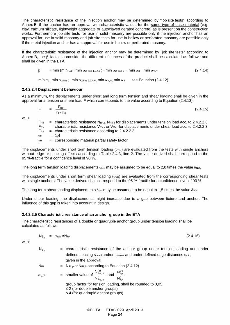
The characteristic resistance of the injection anchor may be determined by "job site tests" according toAnnex B, if the anchor has an approval with characteristic values for the same type of base material (e.g.clay, calcium silicate, lightweight aggregate or autoclaved aerated concrete) as is present on the constructionworks. Furthermore job site tests for use in solid masonry are possible only if the injection anchor has anapproval for use in solid masonry and job site tests for use in hollow or perforated masonry are possible onlyif the metal injection anchor has an approval for use in hollow or perforated masonry.
If the characteristic resistance of the injection anchor may be determined by "job site tests" according toAnnex B, the factor to consider the different influences of the product shall be calculated as follows andshall be given in the ETA.
= min (min 1 ; min 2, line 1,3,4,6 ) ∙ min 2, line 2 ∙ min 3 ∙ min V,N (2.4.14)
min 1, min 2,line 2, min 2,line 1,3,4,6, min V,N, min 3 see Equation (2.4.12)
2.4.2.2.4 Displacement behaviourAs a minimum, the displacements under short and long term tension and shear loading shall be given in theapproval for a tension or shear load F which corresponds to the value according to Equation (2.4.13).
F =MF
RkF
(2.4.15)
with:FRk = characteristic resistance NRk,p, NRk,b for displacements under tension load acc. to 2.4.2.2.3FRk = characteristic resistance VRk,s or VRk,b for displacements under shear load acc. to 2.4.2.2.3FRk = characteristic resistance according to 2.4.2.2.3F = 1,4M = corresponding material partial safety factor
The displacements under short term tension loading (NO) are evaluated from the tests with single anchorswithout edge or spacing effects according to Table 2.4.3, line 2. The value derived shall correspond to the95 %-fractile for a confidence level of 90 %.
The long term tension loading displacements N may be assumed to be equal to 2,0 times the value NO.
The displacements under short term shear loading (VO) are evaluated from the corresponding shear testswith single anchors. The value derived shall correspond to the 95 %-fractile for a confidence level of 90 %.
The long term shear loading displacements V may be assumed to be equal to 1,5 times the value VO.
Under shear loading, the displacements might increase due to a gap between fixture and anchor. Theinfluence of this gap is taken into account in design.
2.4.2.2.5 Characteristic resistance of an anchor group in the ETAThe characteristic resistances of a double or quadruple anchor group under tension loading shall becalculated as follows:
gRkN = g,N NRk (2.4.16)
with:gRkN = characteristic resistance of the anchor group under tension loading and under
defined spacing smin,II and/or smin,┴ and under defined edge distances cmin,given in the approval
NRk = NRk,p or NRk,b according to Equation (2.4.12)
g,N = smaller value of rmRu,
gt,mRu,
NN
and rRk
gt,Rk
NN
,
group factor for tension loading, shall be rounded to 0,05≤ 2 (for double anchor groups)≤ 4 (for quadruple anchor groups)

©EOTA ETAG 029_April 2013Page 25
gt,Ru,mN ; gt,
RkN = mean value or 5 %-fractile of the ultimate loads of an anchor group in a test seriesaccording to Table 2.4.3, line 6
rmRu,N ; r
RkN = mean value or 5 %-fractile of ultimate loads of a single anchor in the relevantreference test according to Table 2.4.3, line 2 (if cmin =ccr) or line 4 (if this optionaltest is performed)
The characteristic resistances of a double or quadruple anchor group under shear loading shall be calculatedas follows:
gRkV = g,V VRk (2.4.17)
with:gRkV = characteristic resistance of the anchor group under shear loading and under
defined spacing smin,II and/or smin,┴ and under defined edge distances cmin,given in the approval
VRk = VRk,b according to Equation (2.4.13)
g,V = smaller value of rmRu,
gt,mRu,
V
Vand r
Rk
gt,Rk
VV
,
group factor for shear loading, shall be rounded to 0,05≤ 2 (for double anchor groups)≤ 4 (for quadruple anchor groups)
gt,mRu,V ; gt,
RkV = mean value or 5 %-fractile of the ultimate loads of an anchor group in a test seriesaccording to Table 2.4.3, line 7
rmRu,V ; r
RkV = mean value or 5 %-fractile of ultimate loads of a single anchor in the relevantreference test according to Table 2.4.3, line 3 (if cmin =ccr) or line 5 (if this optionaltest is performed)
In general, a linear interpolation between the characteristic resistance of a single anchor and thecharacteristic resistance of an anchor group depending on the spacing is not allowed. If there are sufficienttest results with anchor groups in the same masonry units available, which show a clear dependencybetween the load-bearing capacity and the anchor spacing and/or the edge distance, it is possible to evaluatethem and to take them into account in the approval.
2.5 Verification methods relating to Safety in Case of Fire (ER 2)
2.5.1 Reaction to fire
The reaction to fire performance of the anchor shall be in accordance with laws, regulations andadministrative provisions applicable to the anchor in its intended end use application. This performance shallbe expressed in the form of classification specified in accordance with the relevant EC decision and theappropriate CEN classification standards.
The metal parts of injection anchors and the cementitious mortar are assumed to satisfy the requirements forClass A1 of the characteristic reaction to fire, in accordance with the provisions of EC Decision 96/603/EC (asamended) without the need for testing on the basis of its listing in that Decision.
The bonding material (synthetic mortar, cementitious mortar or a mixture of the two including fillers and/oradditives) is located between the metal anchor rod and the wall of the drilled hole in the end use. Thethickness of the mortar layer is about 1 to 2 mm and most of the mortar is material classified class A1according to EC Decision 96/603/EC. Therefore it may be assumed that the bonding material (syntheticmortar or a mixture of synthetic mortar and cementitious mortar) in connection with the injection anchor in theend use application do not make any contribution to fire growth or to the fully developed fire and they have noinfluence to the smoke hazard.
In the context of this end use application of the anchorages the bonding material can be considered to satisfyany reaction to fire requirements.

©EOTA ETAG 029_April 2013Page 26
2.5.2 Resistance to fire
The resistance to fire performance of the assembled system of which the anchor form part shall be inaccordance with laws, regulations and administrative provisions applicable to the assembled system of whichthe anchor form part in its intended end use application. This performance shall be expressed in the form of aclassification specified in accordance with the relevant EC decision and the appropriate CEN classificationstandards.
The suitability of a injection anchor for use in a system that is required to provide a specific fire resistanceclass, shall be assessed according to the EOTA Technical Report N° 020 "Evaluation of anchorages inconcrete concerning Resistance to Fire" [7].
2.6 Verification methods relating to Hygiene, Health and the Environment (ER 3)
The applicant shall either:
- submit the chemical constitution and composition of the materials and components of the product tothe Approval Body which will observe strict rules of confidentialityor
- submit a written declaration to the Approval Body stating whether or not and in which concentration thematerials and components of the product contain substances which have to be classified as dangerousaccording to Directive 67/548/EEC and Regulation (EC) No 1272/2008 and listed in the "Indicative liston dangerous substances" of the EGDS, taking into account the installation conditions of theconstruction product and the release scenarios resulting from there.
The use of recycled materials shall always be indicated, because this could lead to the implementation offurther assessment and verification methods.
The information concerning the presence of dangerous substances listed in Council Directive 67/548/EECand Regulation (EC) No 1272/2008 regulated at European level and listed in the "Indicative list on dangeroussubstances" of the EGDS and/or of other dangerous substances, shall be circulated as part of the evaluationreport by the issuing Approval Body to the other Approval Bodies, under strict conditions of confidentiality.
2.6.1 Method of verification (Release of dangerous substances)
The product and/or constituents of the product listed in the EOTA TR 034: "General Checklist forETAGs/CUAPs/ETAs – Content and/or release of dangerous substances in products/kits”, which have to beconsidered will be verified by the given methods taking into account the installation conditions of theconstruction product and the release scenarios resulting from there. Regulations related to placing theproduct on the market may also need to be taken into account.
Regarding the release scenarios referred to in the EOTA TR 034, the use category IA2 (Product with nodirect contact to (e.g. covered products) but possible impact on indoor air) have to be considered.
2.6.2 Method of assessing and judging (Release of dangerous substances)
The product and/or constituents of the product listed in the EOTA TR 034: "General Checklist forETAGs/CUAPs/ETAs – Content and/or release of dangerous substances in products/kits”, which have to beconsidered will be verified by the given methods taking into account the installation conditions of theconstruction product and the release scenarios resulting from there. Regulations related to placing theproduct on the market may also need to be taken into account.
The content of cadmium contained in zinc coatings shall be declared by the applicant.
Note (to be implemented in the ETA):
For dangerous substances falling under the scope of the CPD for which:
- no assessment and verification methods are given (or cannot be found in TR 034) or- “no performance determined” is declared or- the chosen verification and assessment method does not comply with the regulatory requirement of a
particular Member State
there might be the necessity for an additional assessment.

©EOTA ETAG 029_April 2013Page 27
2.7 Verification methods relating to Durability
2.7.1 Method of verification
2.7.1.1 Tests for checking durability of the metal parts (corrosion)No special tests are required.
The durability of the coating of the metal part that ensures the suitability and the bearing behaviour of theanchor shall be shown. Furthermore it shall be shown that the coating does not negatively affect the durabilityof the bonding material. No special test conditions can be given in this Guideline for checking the durability ofany coating because this depends on the type of coating. Any appropriate tests shall be decided on by theresponsible Approval Body. Zinc coatings (electroplated or hot dip galvanised) need not be subjected totesting if used under dry internal conditions
2.7.1.2 Tests for checking durability of the bonding materialThe durability of the bonding material (except for cementitious mortar) shall be verified by slice tests. Withslice tests, the sensitivity of installed anchors to different environmental exposures can be shown. The slicetests shall be carried out in concrete. The slice test is described in Annex A, A.5.10 in detail.
Slice tests in an alkaline liquid are required only for applications in use category w/w according to section2.3.2.2 if the injection anchor is installed in:
- masonry from normal weight or lightweight concrete masonry units- joints of masonry made from clay or calcium silicate units filled with non carbonated cementitious
mortar
Slice tests may be omitted for applications in:
- masonry made from normal weight or lightweight concrete masonry units if the characteristicresistance is calculated according to Equation (2.4.12) with 3 = 0,3
- joints of masonry units made out of clay or calcium silicate filled with cementitious mortar, if thecharacteristic resistance of the anchor for the corresponding masonry unit given in the ETA isNRk NRk (concrete brick) with NRk (concrete brick) calculated according to Equation (2.4.12) with3 = 0,5 or the mortar is carbonated over the embedment depth of the anchor.Carbonated mortar may be assumed if the structure is sufficiently old (e.g. 15 years)
2.7.2 Method of assessing and judging
2.7.2.1 Durability of the metal partsThe assessment/testing required with respect to corrosion resistance will depend on the specification of theinjection anchor in relation to its use. Supporting evidence that corrosion will not occur is not required if thesteel parts of the metal injection anchor are protected against corrosion, as set out below:
Injection anchors intended for use in structures subject to dry, internal conditions:
No special corrosion protection is necessary for steel parts as coatings provided for preventingcorrosion during storage prior to use and for ensuring proper functioning (e.g. a zinc coating with aminimum thickness of 5 microns) is considered sufficient.
Injection anchors for use in structures subject to external atmospheric exposure or exposure in permanentlydamp internal conditions:
The metal parts of the anchors shall be made of an appropriate grade of stainless steel. The grade ofstainless steel suitable for the various service environments (marine, industrial, etc.) shall be inaccordance with existing rules. Grade A4 of ISO 3506-1 and 2:2009 [4] or equivalent may be usedunder internal and external or other environmental conditions if no particularly aggressive conditionsexist.

©EOTA ETAG 029_April 2013Page 28
Injection anchors for use in structures subject to external atmospheric exposure or exposure in permanentlydamp internal conditions or particularly aggressive conditions:
If the anchor is to be used in particularly aggressive conditions such as permanent or alternateimmersion in seawater or the splash zone of seawater, chloride atmosphere of indoor swimmingpools or atmosphere with extreme chemical pollution (e.g. in desulphurization plants or road tunnels,where de-icing materials are used) stainless steel material 1.4529, 1.4565 and 1.4547 according toEN 10088-5 [5] can be used.
Where a form of protection (material or coating) other than those mentioned above is specified, it will benecessary to provide evidence in support of its effectiveness in the defined service conditions; with dueregard to the aggressiveness of the conditions concerned.
If an anchor involves the use of different metals, these shall be electrolytically compatible with each other. Indry internal conditions, carbon steel is compatible with malleable cast iron.
Assessment of the durability of the coating is based on the type of coating and the intended conditions of use(i.e. dry internal or external conditions).
Note: Bolts or screws made of galvanised steel with high steel strength (>1 000 N/mm²; property class >10.9) may besensitive to brittle fracture. Therefore the risk of brittle fracture has to be considered in the assessment of such products.Commercial standard rods made of galvanised steel should be used with property class 8.8 at most.
2.7.2.2 Durability of the bonding materialIn the slice tests according to Annex A, A.5.10 it shall be shown that:
- the bond strength of the slices stored in an alkaline liquid is at least as high as that of the bondstrength of the comparison tests on slices stored under normal conditions and
- the bond strength of the slices stored in sulphurous atmosphere media is not smaller than 0,9 timesof the bond strength of the comparison tests on slices stored under normal conditions.
To show compliance with this requirement of the slice tests the factor 3 shall be calculated according toEquation (2.7.1).
3 =dry,um
)stored(um
(2.7.1)
with:um(stored) =mean bond strength of the slices stored in the corresponding atmosphere
(alkaline fluid or in sulphurous),um,dry =mean bond strength of the comparison tests on slices stored under normal condition
The bond strength in the slice tests shall be calculated according to Equation (2.7.2)
u =sl
uhd
N
(2.7.2)
with:Nu = measured maximum loadd = diameter of the embedded parthsl = thickness of slice, measured values
If the value 3 is less than 1,0 for the tests in alkaline fluid and 0.9 for tests in sulphurous atmosphere thenthe characteristic resistance NRk shall be reduced according to 2.4.2.2.3.

©EOTA ETAG 029_April 2013Page 29
3 EVALUATION AND ATTESTATION OF CONFORMITY AND CE MARKING
3.1 System of attestation of conformity
According to the communication of the European Commission, the system of attestation of conformity laiddown in Commission Decision 97/177/EC dated 17 February 1997 of the OJ L 073 dated 14 March 1997, isgiven in Table 3.1.
Table 3.1 – System of attestation of conformity applicable to "Metal injection anchors for use inmasonry"
Product Intended use Level(s) orclass(es)
Attestation ofconformity
system
Metal injection anchorsfor use in masonry
For fixing and/or supporting to masonry,structural elements (which contributes to the
stability of the works) or heavy units1
The system of attestation of conformity referred to above is defined as follows:
System 1: Certification of the conformity of the product by a notified certification body on the basis of:(a) Tasks for the manufacturer:
(1) factory production control;(2) further testing of samples taken at the factory by the manufacturer in accordance with a
prescribed test plan;(b) Tasks for the notified body:
(3) initial type-testing of the product;(4) initial inspection of factory and of factory production control;(5) continuous surveillance, assessment and approval of factory production control.
3.2 Tasks and responsibilities of the manufacturer and notified body
3.2.1 Tasks of the manufacturer
The cornerstones of the actions to be undertaken by the manufacturer of "Metal injection anchors for use inmasonry" in the procedure of attestation of conformity are laid down in Table 3.2.
Table 3.2 is an example only; the control plan depends on the individual manufacturing process and has tobe established between notified body and manufacturer for each product.

©EOTA ETAG 029_April 2013Page 30
Table 3.2 – Control plan for the manufacturer; cornerstones
No Subject/type of control Test or controlmethod
Criteria,if any
Minimumnumber
ofsamples
Minimum frequency ofcontrol
(1) (2) (3) (4) (5) (6)Factory production control (FPC)
[including testing of samples in accordance with a prescribed test plan]1 Metal part / dimensions and
tolerancesMeasuring oroptical
Laid down incontrol plan
3 Every shift or 8 hours ofproduction per machine
2 Metal part / material propertiese.g. tensile strength or hardness,elastic limit, elongation on rupture
e.g. tensile test,hardnesstesting Brinellor Vickers
Laid down incontrol plan
3 Every shift or 8 hours ofproduction per machine
3 Metal part / coating Measuring ofthickness
Laid down incontrol plan
3 Every shift or 8 hours ofproduction per machine
4 Mortar / components / mass Mass Laid down incontrol plan
3 Every shift or 8 hours ofproduction per machine
5 Mortar / condition Laid down incontrol plan
2 Every shift or 8 hours ofproduction per machine
6 Mortar / density Laid down incontrol plan
2 Every shift or 8 hours ofproduction per machine
7 Mortar / viscosity Laid down incontrol plan
2 Every shift or 8 hours ofproduction per machine
8 Fingerprint of bonding material Each batch
3.2.2 Tasks for the notified body
The cornerstones of the actions to be undertaken by the notified body in the procedure of attestation ofconformity for "Metal injection anchors for use in masonry" are laid down in Table 3.3.
Table 3.3 – Control plan for the notified body; cornerstones
No Subject/type of control Test orcontrolmethod
Criteria, ifany
Minimumnumber ofsamples
Minimumfrequencyof control
(1) (2) (3) (4) (5) (6)Initial type-testing of the product (ITT)
1 Initial type testing will be available as part of therequired assessment for issuing European TechnicalApprovals unless there are changes in the productionline or plant.In such cases the ITT has to be agreed between theApproval Body and the notified body.
- - - -
Initial inspection of factory and factory production control (FPC)
2 Ascertain that the factory production control with thestaff and equipment are suitable to ensure a continuousand orderly manufacturing of the injection anchor.
- Laid downin controlplan
- 1
Continuous surveillance, judgment and assessment of factory production control (FPC)3 Verifying that the system of factory production control
and the specified automated manufacturing process aremaintained taking account of the control plan.
- Laid downin controlplan
- 1/year

©EOTA ETAG 029_April 2013Page 31
3.3 CE marking and accompanying information
According to Council Directive 93/68/EEC the CE marking consists of the letters "CE" in the form laid down inthe Directive, followed by the identification number of the notified certification body.
The packaging or the delivery tickets associated with the product shall contain the CE marking and thefollowing accompanied information:- the name and address of the producer (legal entity responsible for the manufacture),- the last two digits of the year in which the CE marking was affixed,- the number of the EC certificate of conformity for the product,- the number of the European Technical Approval,- the number of the ETAG,- size of the anchor,- use category.
Example of CE marking and accompanying information:
Letters "CE"
1234 Identification number of notified certification bodyAny CompanyStreet 1, City,
Country
Name and address of the producer (legal entity responsiblefor the manufacture)
10 Two last digits of year of affixing CE marking1234-CPD-0321 Number of EC certificate of conformity
ETA-06/2135 Number of European Technical ApprovalETAG 029 ETAG number
M10 / Use category b,c and w/w Size / use category
3.4 Marking of the product
Every injection anchor shall be clearly identifiable before installation1) and shall be marked by:
- the name or identifying mark of the producer- the injection anchors identity (commercial name)- the intended use (durability use, e.g. an additional mark for stainless steel anchors to
distinguish them from non-stainless steel anchors). The intended use may be included in the injectionanchor identity.
- the minimum anchorage depth or the maximum admissible thickness of the fixture- if an injection anchor is designed for use at more than one anchorage depth while maintaining the
same thread diameter, the anchorage depths available and used shall be discernible after installationof the injection anchor.
1) For use of commercial standard rods see 4.3

©EOTA ETAG 029_April 2013Page 32
4 ASSUMPTIONS UNDER WHICH THE FITNESS FOR THE INTENDED USE IS ASSESSED
4.1 Design method for anchorages
The assessment of the injection anchor shall be made assuming that one of the design methods given inAnnex C is used. However, if an alternative design method shall be proposed, the Approval Body shall judgethis design method and the relevance of the assessment, in particular the relevance of the tests to beundertaken.
The overall assumption shall be made that the design and dimensioning of anchorages is based on technicalconsiderations and in particular the following:
- Preparation of verifiable calculation notes and drawings for determining the relevant masonry in theregion of the anchorage, the loads to be transmitted and their transmission to the supports of thestructure.
- Consideration not only of direct loads but also the important additional loads caused by restraint ofintrinsic (e.g. shrinkage) or extrinsic deformation (e.g. by temperature variations) in the injectionanchor, in the fixture or in the base material together with verification of the distribution of loads inthese structures and assemblies.
- It is to be ensured that the use category applies and the strength class, density etc. of the basematerial is not lower than that to which the characteristic loads apply.
4.2 Packaging, transport, storage of the product
Any special transport conditions shall be stated on accompanying documents.
Any special storage conditions shall be stated on packaging including:
Storage temperature range,Restrictions such as keeping away from heat and direct sunlight,Expiry date.
4.3 Installation of the product in the works
The loading capacity and reliability of anchorages are greatly affected by the manner in which the injectionanchors are installed. The manufacturer’s installation instructions therefore form a fundamental part of theassessment of the fitness for use of an injection anchor.
This Guideline takes account of a reasonable degree of imperfection in relation to installation and thus controlmethods on site after installation will in general not be necessary. This assumes, however, that gross errorson site will be avoided by use of instructions and correct training of the installers and supervision on site.
The anchor shall be used only as supplied by the manufacturer without exchanging the components of ananchor. Commercial standard threaded rods, washers and hexagon nuts may also be used if the followingrequirements are fulfilled:
1. Material, dimensions and mechanical properties of the metal parts (rod, washer, nut) according to thespecifications given in the ETARemark: The ETA has to contain all details of the metal parts.The material of stainless steel is given according to EN 10088:2009 [5], the mechanical propertiesaccording to EN ISO 898-1 and 2:2009 [8] (galvanised steel) and according to EN ISO 3506-1and 2:2009 [4] (stainless steel).
2. Confirmation of material and mechanical properties of the metal parts by inspection certificate 3.1according to EN 10204:2004 [9]; the documents shall be stored.
3. Marking of the rod with the envisaged embedment depth. This may be done by the manufacturer ofthe rod or the person on the job site.

©EOTA ETAG 029_April 2013Page 33
Installation instructions shall typically include the following:
- Before placing an injection anchor, the checks to be made to ensure that the use category applies.- Plaster or similar materials shall be removed, unless there is information from the planning engineer
that this layer was taken into account.- Holes to be drilled perpendicular (maximum deviation 5°) to the surface unless specifically required
otherwise by the manufacturer’s instructions.- Normally hard metal hammer-drill bits in accordance with ISO or National Standards shall be used.- All special drill bits (e.g. stopdrills or diamond core drill bits) required in accordance with
manufacturer’s installation instructions to be in compliance with the manufacturer’s specifications.This may be checked by comparing the drill bit manufacturer’s declared performance andcharacteristics against the specifications of the anchor manufacturer.
- Instructions for hole cleaning shall specify in detail the type of cleaning equipment to be used, e.g. thevolume of blow out pump and diameter and material of brush, together with the precise cleaningprocedure including the number and order of blowing/brushing actions.
- Injection anchors to be installed ensuring not less than the specified embedment depth. The edgedistance and spacing to be kept to the specified values, no minus tolerances to be allowed.
- Remark to the different installation temperatureTemperature limitsThe following temperature limits shall be specified:
Installation ambient temperature rangeBonding material installation temperature range.
Operational time limitsOpen time and curing time shall be stated in relation to the relevant temperature limits, e.g.:Open time related to bonding material installation temperatureCuring time in relation to installation ambient temperature
If tables are used to indicate times-versus-temperature ranges, they shall be inclusive so that therelevant time is clear for all temperatures within the appropriate range. An accepted example is givenin the following:
Installation ambient Curing timetemperature °C (minutes)
E.g. 5 to ≤ 15 120 min>15 to 25 60 min
The following example is not accepted:
Installation ambient Curing timetemperature °C (minutes)
5 120 min15 60 min
When curing times are stated it shall be made clear that this is the earliest time that the injectionanchor may be torqued or loaded. A longer waiting time may be recommended for proof of ultimateload tests on site; if so, this shall be stated.
Finally it is assumed that the necessary information and appropriate specifications for correct installation areavailable on site and that the person responsible transmits all the necessary information to the installer. It isto be further assumed that installation is carried out by trained personnel under the supervision of the personresponsible for technical matters on site. Where pictograms are used, their meaning shall be clear andunambiguous. If necessary, text in the appropriate language shall be added to clarify the meaning.
5 IDENTIFICATION OF THE CONSTRUCTION PRODUCT
In order to ensure that the injection anchor samples used for the initial assessment conform to thespecification referred to in the approval, it is necessary to identify their relevant specifications andcharacteristics which can influence their functioning, performance or durability.
Identification tests are for verifying the characteristics of the injection anchors, including dimensions,constituent materials, anti-corrosion protection and the marking of the injection anchors and variouscomponents.

©EOTA ETAG 029_April 2013Page 34
Wherever possible, checks shall be carried out on finished components. Where dimensions or other factorsprevent testing to a recognized standard, e.g. tensile properties where the required ratio of length to diameterdoes not exist in the finished component, then the tests shall still be carried out on the finished component ifpracticable, in order to produce results for comparison purposes. Where this is not possible, tests shall becarried out on the raw material; however, it shall be noted that where the production process changes thecharacteristics of the material, then a change to the production process can render the results of these testsinvalid.
A minimum number of each component depending on factors such as the production process and the bagsize is to be taken and dimensions measured and checked against the drawings provided by themanufacturer. The tolerances specified for all components shall be complied with and the dimensions ofthese elements shall conform to the appropriate ISO or European Standards where relevant.
The results obtained shall be assessed to ensure that they are within the manufacturer’s specification.
The product which is the subject of the European Technical Approval shall be identified by:
- Testing of product characteristics as laid down in the following.- Fingerprinting.- Formulation.- Manufacturing process parameters.- Calculations, detailing, drawings.
Metal parts:During tests on the constituent materials of the components of the metal parts, the following properties shallbe determined: tensile strength, elastic limit, elongation at rupture, hardness. The measured values shall becompared with minimum values or strength classes indicated in ISO or European Standards. The manner inwhich the components are fabricated shall also be checked (e.g. cold-forming, quenching, hardening). Forthe testing of carbon steel screws, bolts, nuts, reference can be made to ISO 898-1 and 2. For the testing ofstainless steel screws, bolts, nuts reference can be made to ISO 3506-1 and -2. For quenched components,the surface hardness and case depth are to be determined. Hardness testing shall be by either the Brinell orVickers methods. Wherever possible, the material declaration, according to the relevant material standard,shall be provided.
Bonding material:All components of the bonding materials shall be described in a chemically unambiguous way and beidentified by standard tests (e.g. fingerprinting tests). All component amounts shall be specified either bymass, volume or percentage, with appropriate tolerances.
The following characteristics shall be specified where relevant in accordance with ISO, European or nationalstandards, together with any others as appropriate.
1 Organic Bonding agentsResin, hardener and additives shall be identified by the following tests:
- density- viscosity- ignition loss and ash content- conventional dry extract- grain size analysis- tensile strength- bending strength- compressive strength- open time- reactivity (gel or setting time) (this may be tested with a standardised
formulation, not necessarily that specified for the bonding anchor)
In addition, the following tests are necessary:
Resin and hardener cured by polyaddition mechanismEpoxies- epoxy index (equivalent)- amine equivalent

©EOTA ETAG 029_April 2013Page 35
Polyurethanes- hydroxyl equivalent- isocyanate equivalent
Resin and hardener cured by polymerisationUnsaturated polyester, vinylester (epoxymethacrylates) and vinylesterurethanes(urethanmethacrylates)- hardener (catalyst) content of peroxideMethylmethacrylates (MMA)- hardener, content of peroxide
Filler- specification of filler material (e.g. tested by density) including type- specification of filler shape (e.g. fibre, balls, ...)- grain size analysis
2 Inorganic bonding agents- material specification by chemical analysis- active binder batching- grain size analysis- density- dry extract- setting test- shrinkage and swelling test- bend and compressive strength at 7 and 28 days- ignition loss and ash content
Filler, additives- specification of filler material and additives- specification of filler shape
6 FORMAT OF ETAS ISSUED ON THE BASIS OF THE ETAG
6.1 Definition of the anchor and its intended use
- Definition- Intended use
- Use categories in respect of the base material- Use categories in respect of installation and use- Use categories in respect of to the service temperature range
- Assumed working life
6.2 Characteristics of the anchor with regard to safety in use and methods of verification
- Definition of the base material which was used in the tests (type of material, strength, density, holedimensions, dimensions of the brick)
- Minimum allowable edge distance and minimum allowable spacing- Characteristic edge distance and characteristic spacing- In addition to the specific clauses relating to dangerous substances contained in the European
Technical Approval, there may be other requirements applicable to the products falling within itsscope (e.g. transposed European legislation and national laws, regulations and administrativeprovisions). In order to meet the provisions of the EU Construction Products Directive, theserequirements need also to be complied with, when and where they apply.
Note: For dangerous substances falling under the scope of the CPD for which:
- no assessment and verification methods are given (or cannot be found in TR 034) or- “no performance determined” is declared or- the chosen verification and assessment method does not comply with the regulatory
requirement of a particular Member State
there might be the necessity for an additional assessment.

©EOTA ETAG 029_April 2013Page 36
6.3 Evaluation and attestation of conformity and CE marking
- System of attestation of conformity- Responsibilities- CE-marking
6.4 Assumptions under which the fitness of the product for the intended use was favourablyassessed
- ManufacturingThe ETA is issued for the product on the basis of agreed data/information, deposited with theApproval Body which identifies the product that has been assessed and judged. Changes to theproduct/production process, which could result in this deposited data/information being incorrect,shall be notified to the Approval Body before the changes are introduced. The Approval Body willdecide whether or not such changes affect the ETA and consequently the validity of the CE markingon the basis of the ETA and if so whether further assessment/alterations to the ETA, shall benecessary.
- Design of anchoragesThe anchorages are designed in accordance with the ETAG 029, Annex C.
- Installation
7 REFERENCE DOCUMENTS
[1] Directive relating to construction products (CPD): Council Directive of 21 December 1988 on theapproximation of laws, regulations and administrative provisions of the Member States relating toconstruction products (89/106/EEC) taking account of the modified provisions (93/68/EEC)
[2] EN 771-1 to 5:2011: Specification for masonry units
[3] EN 12602:2008: Prefabricated reinforced components of autoclaved aerated concrete
[4] ISO 3506-1 and 2:2009: Mechanical properties of corrosion-resistant stainless-steel fasteners –Part 1: Bolts, screws and studs; Part 2: Nuts
[5] EN 10088-4 and 5:2009: Stainless steels – Part 4: Technical delivery conditions for sheet/plate andstrip of corrosion resisting steels for construction purposes; Part 5: Technical delivery conditions forbars, rods, wire, sections and bright products of corrosion resisting steels for construction purposes
[6] EN 1996-1-1:2005 + AC:2009: Design of masonry structures. Part 1-1: General rules for reinforcedand unreinforced masonry structure
[7] EOTA: TR 020: Evaluation of Anchorages in Concrete concerning Resistance to Fire
[8I ISO 898-1 and 2:2009: Mechanical properties of fasteners made of carbon steel and alloy steel -Part 1: Bolts, screws and studs with specified properly classes – coarse thread and fine pitch thread;Part 2: Nuts with specified properly classes – coarse thread and fine pitch thread
[9] EN 10204:2004: Metallic products – Types of inspection documents
[10] ISO 5468:2006: Rotary and rotary impact masonry drill bits hard metal tips – Dimensions
[11] EN 1990:2002 + A1:2005 / AC:2010: Eurocode 0: Basis of Structural Design
[12] EN 1991-1-1:2002 + AC:2009: Eurocode 1: Actions on Structures – Part 1-1: General actions –Densities, self-weight, imposed loads for building
[13] EN ISO 6988:1994: Metallic and other non-organic coatings – sulphur dioxide test with generalcondensation of moisture
[14] EOTA: ETAG 001, Annex A: Edition 1997, Amendment November 2006: Guideline for Europeantechnical approval of metal anchors for use in concrete, Annex A: Details of test
©EOTA ETAG 029_April 2013Page 37
[15] EN 1998-1:2004 + AC:2009: Eurocode 8: Design of structures for earthquake resistance – Part 1:General rules, seismic actions and rules for buildings
[16] EN 772-1:2011: Methods of test for masonry units – Part 1: Determination of compressive strength
[17] EOTA: ETAG 001, Part 5: Edition 2002, Amendment November 2012: Guideline for Europeantechnical approval of metal anchors for use in concrete, Part 5: Bonded Anchors
[18] EOTA TR 034 "General Checklist for ETAGs/CUAPs/ETAs - Content and/or release of dangeroussubstances in products/kits”