et 200pro distributed i/o ethernet/ip interface module 200pro distributed i/o ethernet/ip interface...
TRANSCRIPT

ET 200pro distributed I/O EtherNet/IP
interface module
___________________
___________________
___________________
___________________
___________________
___________________
___________________
___________________
___________________
SIMATIC
ET 200pro distributed I/O EtherNet/IP interface module
Manual
03/2016 A5E32861915-AB
Preface 1
Product overview 2
The ET 200pro EtherNet/IP module
3
Installing, mounting, and connecting
4
Commissioning 5
General technical specifications
6
Order number A
Dimension drawing B
Address area C

Siemens AG Division Digital Factory Postfach 48 48 90026 NÜRNBERG GERMANY
A5E32861915-AB 03/2016 Subject to change
Copyright © Siemens AG 2014 - 2016. All rights reserved
Legal information Warning notice system
This manual contains notices you have to observe in order to ensure your personal safety, as well as to prevent damage to property. The notices referring to your personal safety are highlighted in the manual by a safety alert symbol, notices referring only to property damage have no safety alert symbol. These notices shown below are graded according to the degree of danger.
DANGER indicates that death or severe personal injury will result if proper precautions are not taken.
WARNING indicates that death or severe personal injury may result if proper precautions are not taken.
CAUTION indicates that minor personal injury can result if proper precautions are not taken.
NOTICE indicates that property damage can result if proper precautions are not taken.
If more than one degree of danger is present, the warning notice representing the highest degree of danger will be used. A notice warning of injury to persons with a safety alert symbol may also include a warning relating to property damage.
Qualified Personnel The product/system described in this documentation may be operated only by personnel qualified for the specific task in accordance with the relevant documentation, in particular its warning notices and safety instructions. Qualified personnel are those who, based on their training and experience, are capable of identifying risks and avoiding potential hazards when working with these products/systems.
Proper use of Siemens products Note the following:
WARNING Siemens products may only be used for the applications described in the catalog and in the relevant technical documentation. If products and components from other manufacturers are used, these must be recommended or approved by Siemens. Proper transport, storage, installation, assembly, commissioning, operation and maintenance are required to ensure that the products operate safely and without any problems. The permissible ambient conditions must be complied with. The information in the relevant documentation must be observed.
Trademarks All names identified by ® are registered trademarks of Siemens AG. The remaining trademarks in this publication may be trademarks whose use by third parties for their own purposes could violate the rights of the owner.
Disclaimer of Liability We have reviewed the contents of this publication to ensure consistency with the hardware and software described. Since variance cannot be precluded entirely, we cannot guarantee full consistency. However, the information in this publication is reviewed regularly and any necessary corrections are included in subsequent editions.

ET 200pro distributed I/O EtherNet/IP interface module Manual, 03/2016, A5E32861915-AB 3
Table of contents
1 Preface ................................................................................................................................................... 5
2 Product overview .................................................................................................................................... 8
2.1 What are distributed I/O systems? ............................................................................................ 8
2.2 What is the ET 200pro distributed I/O system? ........................................................................ 9
2.3 Components of the ET200pro distributed I/O system ............................................................. 12
2.4 The ET 200pro EtherNet/IP interface module ........................................................................ 14
2.5 Features and benefits of the ET 200pro EtherNet/IP module................................................. 16
3 The ET 200pro EtherNet/IP module....................................................................................................... 17
3.1 ET 200pro EtherNet/IP module hardware............................................................................... 17
3.2 Operation ................................................................................................................................ 19
3.3 Parameters for the ET 200pro EtherNet/IP module ................................................................ 22
3.4 Faults ...................................................................................................................................... 23
3.5 Troubleshooting ...................................................................................................................... 26
3.6 Replacing a faulty ET 200pro EtherNet/IP module ................................................................. 28
3.7 Device profile: supported CIP objects ..................................................................................... 29 3.7.1 Identity Object ......................................................................................................................... 29 3.7.2 Assembly Object ..................................................................................................................... 32 3.7.3 Connection Manager Object ................................................................................................... 34 3.7.4 TCP/IP Interface Object .......................................................................................................... 35 3.7.5 EtherNet Link Object ............................................................................................................... 38
3.8 Device profile: vendor-specific objects ................................................................................... 41 3.8.1 Adapter Object ........................................................................................................................ 41 3.8.2 Slot Object .............................................................................................................................. 45
3.9 Technical specifications .......................................................................................................... 49
4 Installing, mounting, and connecting ...................................................................................................... 51
4.1 Installing .................................................................................................................................. 51
4.2 Mounting ................................................................................................................................. 51
4.3 Connecting .............................................................................................................................. 52

Table of contents
ET 200pro distributed I/O EtherNet/IP interface module 4 Manual, 03/2016, A5E32861915-AB
5 Commissioning ..................................................................................................................................... 53
5.1 Configuring the ET 200pro EtherNet/IP module .................................................................... 53
5.2 Setting the IP address ............................................................................................................ 53
5.3 Grouping electronic modules ................................................................................................. 54
5.4 Commissioning and startup ................................................................................................... 58
5.5 Using QuickConnect .............................................................................................................. 59 5.5.1 QuickConnect overview ......................................................................................................... 59 5.5.2 Guidelines for using QuickConnect on your network ............................................................. 60 5.5.3 Replacing a faulty QuickConnect Adapter ............................................................................. 63 5.5.4 Troubleshooting and optimization .......................................................................................... 64
5.6 Firmware updates .................................................................................................................. 65
6 General technical specifications ............................................................................................................ 66
6.1 Standards and approvals ....................................................................................................... 66
6.2 Electromagnetic compatibility ................................................................................................ 69
6.3 Shipping and storage conditions ............................................................................................ 70
6.4 Mechanical and climatic environmental conditions ................................................................ 71
6.5 Specifications for insulation tests, protection class, degree of protection, and rated voltage .................................................................................................................................... 74
A Order number ....................................................................................................................................... 76
B Dimension drawing ............................................................................................................................... 77
C Address area ........................................................................................................................................ 78
Index .................................................................................................................................................... 79

ET 200pro distributed I/O EtherNet/IP interface module Manual, 03/2016, A5E32861915-AB 5
Preface 1 Trademarks
This manual references technologies whose names are trademarked by ODVA, the Open DeviceNet Vendors Association. The ODVA technologies referenced in this manual include:
EtherNet/IP™
CIP™ (Common Industrial Protocol)
QuickConnect™
For more information on ODVA and its trademarked technologies, visit the ODVA website (http://www.odva.org).
Purpose of the manual The information in this manual is intended to enable you to operate the ET 200pro EtherNet/IP interface module on EtherNet/IP.
Required level of knowledge You require knowledge of the automation engineering field in order to use the material in this manual.
Scope of the manual This manual is valid for the ET 200pro EtherNet/IP module. Appendix A provides order information.
This manual contains a description of the components that were valid at the time the manual was published. Information about new components and new versions of components is released in Product Information bulletins available on the Siemens Industry Online Support (https://support.industry.siemens.com/cs/?lc=en-US) website.
Certifications, Marks, and Standards The ET 200pro EtherNet/IP module complies with EtherNet/IP Specification CIP Networks Library Volume 2: EtherNet/IP Adaption of CIP, Edition 1.16.
See the "General technical specifications" chapter for a full description of all applicable certifications, marks, and standards.
Preface
ET 200pro distributed I/O EtherNet/IP interface module 6 Manual, 03/2016, A5E32861915-AB
Relevant manuals The following manuals are included on the disk that shipped with your ET 200pro EtherNet/IP module:
ET 200pro EtherNet/IP interface module System Manual (this manual)
ET 200pro distributed I/O System Operating Instructions
EIP ET200 Configuration Tool User Reference Guide
The following manual is also relevant to the ET 200pro system. They can be found on the Siemens Industry Online Support (https://support.industry.siemens.com/cs/?lc=en-US) website:
ET 200pro Motor starters Manual
Software In order to configure the ET 200pro EtherNet/IP module, you require the EIP ET200 Configuration Tool software. This software is located on the companion disk that shipped with your ET 200pro EtherNet/IP module.
Recycling and disposal Because it is low in contaminants, the ET 200pro EtherNet/IP module is recyclable. Contact a certified electronic waste disposal company to recycle and dispose of your old equipment in an environmentally-friendly manner.
Online product support If you have questions about using the ET 200pro EtherNet/IP module that the documentation does not address, go to the Siemens Industry Online Support (https://support.industry.siemens.com/cs/?lc=en-US) website and search on "ET 200pro".

Preface
ET 200pro distributed I/O EtherNet/IP interface module Manual, 03/2016, A5E32861915-AB 7
Security information Siemens provides products and solutions with industrial security functions that support the secure operation of plants, solutions, machines, equipment and/or networks. They are important components in a holistic industrial security concept. With this in mind, Siemens’ products and solutions undergo continuous development. Siemens recommends strongly that you regularly check for product updates.
For the secure operation of Siemens products and solutions, it is necessary to take suitable preventive action (e.g. cell protection concept) and integrate each component into a holistic, state-of-the-art industrial security concept. Third-party products that may be in use should also be considered. You can find more information about industrial security on the Internet (http://www.siemens.com/industrialsecurity).
To stay informed about product updates as they occur, sign up for a product-specific newsletter. You can find more information on the Internet (http://support.automation.siemens.com).

ET 200pro distributed I/O EtherNet/IP interface module Manual, 03/2016, A5E32861915-AB 8
Product overview 2 2.1 What are distributed I/O systems?
When a system is set up, the inputs and outputs from and to the process are often located centrally in the programmable logic controller.
If there are inputs and outputs at considerable distances from the PLC, there may be long runs of cabling that are not immediately comprehensible. Additionally, electromagnetic interference may impair reliability.
Using a distributed I/O system provides the following benefits:
The controller CPU is located centrally.
The I/O systems (inputs and outputs) operate locally on a distributed basis.
The high-performance ET 200pro system ensures that the PLC and I/O systems communicate smoothly.

Product overview 2.2 What is the ET 200pro distributed I/O system?
ET 200pro distributed I/O EtherNet/IP interface module Manual, 03/2016, A5E32861915-AB 9
2.2 What is the ET 200pro distributed I/O system? The ET 200pro distributed I/O system is a modular distributed I/O system available in degrees of protection IP65, IP66, and IP67.
Fields of application A robust design and degree of protection IP65, IP66, or IP67 make the ET 200pro EtherNet/IP module particularly suitable for use in rugged industrial environments.
With IP65, IP66 and IP67, the ET 200pro EtherNet/IP module is protected against the ingress of foreign bodies and water. The module does not require an additional enclosure.
The ET 200pro EtherNet/IP module supports communication with:
Fieldbus
Fieldbus Data Link Layer
For more information, see the topic "Standards and approvals".
Area of application With the ET 200pro system, you can connect virtually any number of I/O modules in virtually any combination right next to the interface module. This means that you can adjust the configuration to suit local requirements.
Configuration The ET 200pro EtherNet/IP module is installed on a rack and basically consists of the following:
An interface module that transfers data to the EtherNet/IP master
Up to 16 electronic modules with maximum 1 m total width (without rack)
Connection modules in various designs for
– ET 200pro EtherNet/IP module
– Supply voltages
– Inputs and outputs
Pneumatic interface modules for linking of FESTO valve terminals
You can thus set the focus of your configuration on local requirements.
The convenient handling features of ET 200pro EtherNet/IP module ensure quick commissioning and easy maintenance.
Terminal modules and electronic modules The ET 200pro distributed I/O system consists primarily of various passive connection modules to which you connect the electronic modules and motor starters.
The ET 200pro EtherNet/IP module enables the ET 200pro distributed I/O system to be connected to the EtherNet/IP network.

Product overview 2.2 What is the ET 200pro distributed I/O system?
ET 200pro distributed I/O EtherNet/IP interface module 10 Manual, 03/2016, A5E32861915-AB
Example configuration with electronic modules The ET 200pro EtherNet/IP module can be equipped up to the maximum configuration with electronic modules. Between an interface module and a terminating module you can adapt the electronic modules to your application in whatever configuration you require.
The figure below shows an example configuration of the ET 200pro distributed I/O system.
① ET 200pro EtherNet/IP interface module (with connection module)
② 8 DI DC 24V
③ 4 DO DC 24V/2.0A
④ 4 AI U HF
⑤ 4 AI I HF
⑥ 8 DI DC 24V
⑦ Terminating module
⑧ 8 x switches, sensors
⑨ 4/8 x load
⑩ 4 x voltage measurement
⑪ 4 x current measurement for 2-/4-wire measuring transducer
⑫ Actuator/sensor distributor

Product overview 2.2 What is the ET 200pro distributed I/O system?
ET 200pro distributed I/O EtherNet/IP interface module Manual, 03/2016, A5E32861915-AB 11
Example configuration with electronic module and motor starter Between an interface module and a terminating module you can adapt the electronic modules, motor starters and frequency converters to your applications in whatever configuration you require.
The figure below shows an example configuration of the ET 200pro distributed I/O system with motor starter and repair switch module.
① ET 200pro EtherNet/IP interface module (with connection module)
② Repair switch module
③ DSe; Standard
④ 8 DI DC 24 V
⑤ Terminating module
⑥ Cap
⑦ Motor connection
⑧ Power jumper plug
⑨ Infeed

Product overview 2.3 Components of the ET200pro distributed I/O system
ET 200pro distributed I/O EtherNet/IP interface module 12 Manual, 03/2016, A5E32861915-AB
2.3 Components of the ET200pro distributed I/O system The table below lists the most important components of an ET 200pro system.
Component Function View Rack The ET 200pro is mounted onto the rack.
Four versions with different lengths are avail-able:
Rack, narrow ①
Rack, wide ②
Rack, compact narrow ③
Rack, compact wide ④
Interface module for EtherNet/IP with bus module and terminat-ing module
The interface module interconnects ET 200pro with the EtherNet/IP master and prepares the data for the electronic modules. The unit is delivered with the terminating module ②, and the interface module ① is already mounted on the bus module. • The bus module is the mechanical and
electrical connection element between the various ET 200pro modules.
• The terminating module terminates the ET 200pro, backplane bus.
The following interface modules are available for EtherNet/IP: • ET 200pro EtherNet/IP interface module
(ZNX:EIP200PRO)

Product overview 2.3 Components of the ET200pro distributed I/O system
ET 200pro distributed I/O EtherNet/IP interface module Manual, 03/2016, A5E32861915-AB 13
Component Function View Connection module for the ET 200pro Ether-Net/IP interface mod-ule
The connection module is mounted on the interface module. It is used to connect EtherNet/IP and the electronic, encoder, and load voltage supplies. The following connection module is available for EtherNet/IP: • CM IM M12, 7/8" (ZNX:ET200PROCM1)
Power module with bus module and outgoing module
① The power module provides a new poten-tial group for the 2L+ load voltage supply. The unit is shipped with the power module mounted on the bus module.
② The outgoing module enables the 1L+ electronics/encoder supply and the 2L+ load voltage supply to be tapped.

Product overview 2.4 The ET 200pro EtherNet/IP interface module
ET 200pro distributed I/O EtherNet/IP interface module 14 Manual, 03/2016, A5E32861915-AB
2.4 The ET 200pro EtherNet/IP interface module
ET 200pro EtherNet/IP interface module package The ET 200pro EtherNet/IP interface module package includes the following components:
Interface module and terminating module (ET 200pro EtherNet/IP)
Companion disk with EIP ET200 Configuration Tool software, EIP ET200 Configuration Tool User Reference Guide, and this ET 200pro EtherNet/IP interface module manual
Order number The order number for this package is: ZNX:EIP200PRO.
ET 200pro EtherNet/IP interface module features The ET 200pro EtherNet/IP module is a communications adapter for interfacing with an ET 200pro distributed I/O system. It provides connectivity between an EtherNet/IP network and ET 200pro power and I/O modules, and has the following features:
It prepares the data for electronic modules and motor starters.
It supplies the backplane bus.
The maximum address space is 255 bytes for inputs and 255 bytes for outputs.
The connection between 1M and FE is not applicable in a configuration with ungrounded reference potential.
A maximum of 16 modules can be operated with the interface module.
The maximum width of the station is 1 m.
The maximum parameter length for the entire station is 237 bytes.
You can group modules within one byte (packing).
Note Operating with ungrounded reference potential
When the ET 200pro EtherNet/IP module is operated with ungrounded reference potential and 1M and FE are not interconnected, any interference currents are discharged to protective ground via an internal RC circuit.

Product overview 2.4 The ET 200pro EtherNet/IP interface module
ET 200pro distributed I/O EtherNet/IP interface module Manual, 03/2016, A5E32861915-AB 15
The following illustration shows the hardware features of the ET 200pro EtherNet/IP module:
① Status LEDs
② Connection module interface
③ Coding element
④ Ground connections
⑤ Power connection
I/O features The ET 200pro EtherNet/IP module provides the following I/O features:
Provides support for a subset of ET 200pro modules
Supports up to 16 modules per ET 200pro EtherNet/IP module
Supports electronic module parameterization
Supports electronic module diagnostics

Product overview 2.5 Features and benefits of the ET 200pro EtherNet/IP module
ET 200pro distributed I/O EtherNet/IP interface module 16 Manual, 03/2016, A5E32861915-AB
2.5 Features and benefits of the ET 200pro EtherNet/IP module The following table lists the features and benefits of the ET 200pro EtherNet/IP module: Features Benefits
Structure Finely-graduated modular design: • 4/8/16 channel electronic modules • Power modules • Integrated motor starters
• Function-oriented, cost-optimized station design • Considerable reduction in outlay for configuration
and documentation • Space savings due to arbitrary arrangement of
the modules
Extensive range of electronic modules Broad area of application Communication capacity, system-integrated motor starter: direct and reversing starter to 7.5 kW
PLC inputs and outputs, terminal blocks, circuit breakers and contactors in a plug-in module save space and the effort involved in wiring
Permanent wiring due to the separation of the connection module and electronic components
• Prewiring possible • Module replacement during operation of the
ET 200pro EtherNet/IP module ("hot swapping")
Individual connection of power modules to common potential
• Individual formation of potential groups • Simple load interruption
Robust structure for rough industrial condi-tions (10 g vibration resistance)
High operating reliability when mounted directly on the machine, high availability
Connection system Integrated voltage buses Reduced effort required for wiring Power bus up to 25 A for motor starters Minimization of wiring in 400 V range M8, M12, and M23 connections A change in terminal connection method is not nec-
essary
• 2- and 3-wire connection, or • 2-, 3- and 4-wire connection
Optimal selection on grounds of space and cost
IP65, IP66, and IP67 connection modules A change in connection method is not necessary Automatic coding of the I/O modules Quick and reliable module replacement Large label plate Adequate space for clear identification With motor starters up to safety category 4 in accordance with EN 954-1
Saves money on costly safety equipment

ET 200pro distributed I/O EtherNet/IP interface module Manual, 03/2016, A5E32861915-AB 17
The ET 200pro EtherNet/IP module 3 3.1 ET 200pro EtherNet/IP module hardware
Hardware configuration You can operate your ET 200pro EtherNet/IP module in automatic configuration mode, or you can use the EIP ET200 Configuration Tool software to operate in user configured mode.
The software and associated User Reference Guide can be found on the companion disk that shipped with your module, or downloaded from the Siemens Industry Online Support (https://support.automation.siemens.com/cs/?lc=en-US) website.
LED status indicators The ET 200pro EtherNet/IP module has three bi-color LEDs that provide diagnostic information about the current state of the device and provide an indication of any faults. The LEDs conform to the behaviors defined in the ODVA EtherNet/IP Adaptation of CIP Adapter Specification for the Module Status and Network Status LEDs, and in this manual for I/O Status LEDs.
LED status indicator: Module Status LED The bi-color Module Status LED indicates the current state of the ET 200pro EtherNet/IP module, as described in the following table: State Description Off No power applied to device. Flashing green Device has not been configured.
Invalid parameter data. Green Device has initialized successfully and no errors
were detected. Flashing red Recoverable fault.
Device needs commissioning due to configuration error: • Invalid parameter data • Invalid slot configuration data.
Red Unrecoverable fault detected: hardware failure.

The ET 200pro EtherNet/IP module 3.1 ET 200pro EtherNet/IP module hardware
ET 200pro distributed I/O EtherNet/IP interface module 18 Manual, 03/2016, A5E32861915-AB
LED status indicator: Network Status LED The bi-color Network Status LED indicates the current state of the ET 200pro EtherNet/IP communications link, as described in the following table: State Description Off • Device is powered off, or is powered on but
does not have an IP address. • May be waiting for IP address if in
DHCP/BOOTP mode.
Flashing green No connection - an IP address is configured, but no CIP connections are established.
Green Connected. Flashing red One or more CIP connections have timed out. Red Duplicate IP address detected.
LED status indicator: I/O Status LED The bi-color I/O Status LED provides diagnostic information about the current state of the I/O under the control of the ET 200pro EtherNet/IP module, as described in the following table: State Description Off • All outputs and inputs are inactive.
• Configuration errors prevent enabling of in-puts/outputs.
• No connection. • Device not powered.
Green Device online with connections established (nor-mal operation, RUN mode).
Flashing green • Device online with connections established (normal operation, IDLE mode).
• Firmware update in progress.
Flashing red One or more outputs or inputs are faulted when I/O is active.

The ET 200pro EtherNet/IP module 3.2 Operation
ET 200pro distributed I/O EtherNet/IP interface module Manual, 03/2016, A5E32861915-AB 19
3.2 Operation The ET 200pro EtherNet/IP interface module is capable of operating out of the box in Automatic Configuration mode without any special configuration software. Automatic Configuration mode is the default mode.
However, to take full advantage of advanced diagnostics and features, you can operate in User-configured mode by using the EIP ET200 Configuration Tool software.
You can access the Configuration Tool software and associated User Reference Guide in one of two places:
on the companion disk that shipped with your ET 200pro EtherNet/IP interface module
on the Siemens Industry Online Support website (https://support.automation.siemens.com/cs/?lc=en-US)
Automatic Configuration mode When operating in Automatic Configuration mode, the ET 200pro EtherNet/IP module configures its I/O sizes, I/O module parameterization data, and configuration data according to the combination of ET 200pro modules present at power-up or reset. In Automatic Configuration mode:
Electronic module parameter data cannot be specified. The modules use the default parameters. You must make certain that the default parameters for the modules satisfy your application requirements.
I/O configuration cannot be verified. The ET 200pro EtherNet/IP module verifies the configuration by examining I/O sizes.
Note that the ET 200pro EtherNet/IP module is unable to differentiate modules of similar configuration types (for example, a 2 A discrete output module as compared to a 0.5 A discrete output module):
The I/O data format is defined by the combination of modules installed.
I/O module grouping is enabled.
The I/O status byte is enabled.
Note
Motor starters require User-configured mode.

The ET 200pro EtherNet/IP module 3.2 Operation
ET 200pro distributed I/O EtherNet/IP interface module 20 Manual, 03/2016, A5E32861915-AB
User-configured mode When operating in User-configured mode, the ET 200pro EtherNet/IP module I/O sizes, I/O module parameterization data, and I/O configuration data are stored in nonvolatile memory and accessed via the Slot Object. In User-configured mode:
You can modify electronic module parameter data, allowing access to more advanced configuration options and diagnostics.
I/O configuration is verified. Mismatching I/O configurations result in an error.
Note that the ET 200pro EtherNet/IP module is unable to differentiate modules of similar configuration types (for example, a 2 A discrete output module as compared to a 0.5 A discrete output module).
You can set Slot Object instance attributes (as long as there are no open I/O connections).
You define the I/O data format by the combination of modules you configure.
I/O module grouping is available, but you must define it by your configuration selections.
Changes to configuration data Changes to user configuration data take effect immediately after download without resetting the device.
Changes to user configuration data are stored in nonvolatile memory immediately (before the explicit message response is sent).
Setting the IP address DHCP is the factory default. When the ET 200pro EtherNet/IP module is using DHCP, you can set IP addresses by using Microsoft Windows and Linux DHCP/BOOTP servers. There are several free servers for Microsoft Windows available for download from the Internet. Use discretion when downloading software from the Internet.
After you set the IP address with DHCP, you can use the EIP ET200 Configuration Tool to set a permanent IP address and turn off DHCP. See the "EIP ET200 Configuration Tool User Reference Guide" for detailed instructions.
I/O status byte The Adapter Object IO_StatusEnable attribute allows you to enable or disable the generation of an additional I/O status byte to detect faults in the ET 200pro EtherNet/IP. If the IO_StatusEnable attribute is TRUE (1), an additional status byte is placed at the beginning of the input data packet, prior to any electronic module data. In the event of a fault, the status byte is set to 1, and the I/O status LED flashes red while I/O is active.
If the IO_StatusEnable attribute is FALSE (0), the input data packet contains only electronic module data as configured.

The ET 200pro EtherNet/IP module 3.2 Operation
ET 200pro distributed I/O EtherNet/IP interface module Manual, 03/2016, A5E32861915-AB 21
Module grouping The ET 200pro EtherNet/IP module supports grouping electronic module data to enable more efficient data transfer and use of address space. Electronic module data is always grouped in Automatic Configuration mode. See the topic "Configuring the ET 200pro EtherNet/IP module" for details about grouping module data.
Reset behavior When the ET 200pro EtherNet/IP module is reset, the outputs are deactivated during the short period that the reset is in progress. The unit can be reset in the following ways:
by cycling of primary device 24 VDC power of the primary device
by using the reset function in the EIP ET200 Configuration Tool.
by sending an explicit EtherNet/IP Reset service message to instance 1 of the Identity Object with service data of 0, 1, or 2. If service data 1 is sent, on reset the module returns to factory default state and any user configuration is lost. If service data 2 is sent, the module returns to the factory default state, but the IP address is maintained.
Note
When network power is removed (or if an I/O connection times out or is lost), outputs go to their configured "substitute" value according to how the parameter is set for each I/O module. The "default" substitute value, which is in effect in Automatic Configuration mode, is to turn off or to zero outputs. Consult the documentation for your specific I/O module for details. To set a non-default substitute value, you must use User-configured mode.

The ET 200pro EtherNet/IP module 3.3 Parameters for the ET 200pro EtherNet/IP module
ET 200pro distributed I/O EtherNet/IP interface module 22 Manual, 03/2016, A5E32861915-AB
3.3 Parameters for the ET 200pro EtherNet/IP module
Parameter assignment Parameters for the ET 200pro EtherNet/IP module are set by using the EIP ET200 Configuration Tool software. After loading new parameters into the interface module, the parameters take effect immediately.
The following table describes the parameters of the ET 200pro EtherNet/IP interface module as they appear in the Configuration Tool: Parameter Value range Default Operation for ref. <> actual conf. enable disable disable Identifier-related diagnostics enable disable enable Submodule status enable disable enable Channel-related diagnostics enable disable enable Option handling not currently supported
Parameter description
Operation for ref. <> actual conf.
If this parameter is enabled and:
you hot-swap an electronic module, this will not cause a failure of the ET 200pro station.
the preset and actual configurations do not match, ET 200pro can still exchange data with the PLC.
If this parameter is disabled and:
you hot-swap an electronic module, this will cause a failure of the ET 200pro station.
the preset and actual configurations do not match, ET 200pro cannot exchange data with the PLC.
Identifier-related diagnostics
This parameter has no effect for the ET 200pro EtherNet/IP module. All of the diagnostic data is always available through the Adapter Object.
Submodule status
This parameter has no effect for the ET 200pro EtherNet/IP module. All of the diagnostic data is always available through the Adapter Object.
Channel-related diagnostics
This parameter has no effect for the ET 200pro EtherNet/IP module. All of the diagnostic data is always available through the Adapter Object.

The ET 200pro EtherNet/IP module 3.4 Faults
ET 200pro distributed I/O EtherNet/IP interface module Manual, 03/2016, A5E32861915-AB 23
Option handling
This parameter is not currently supported.
3.4 Faults
Configuration faults Faults in the electronic module configuration and parameterization data are handled slightly differently depending on when they are detected.
Regardless of the detection time, the following occur:
The Adapter Object AdapterStatus attribute indicates the appropriate code.
The Identity Object Status attribute indicates a minor recoverable fault.
When the fault is detected at power-up or as a result of a hot swap when no I/O connections are open:
An attempt to open I/O connections results in a Device State Conflict error.
A fault detected as a result of a hot-swap when one or more I/O connections are open result in the following behavior:
If the IO_StatusEnable attribute is TRUE, a fault is indicated in the I/O Status byte at the beginning of the input data packet.
Output data from the scanner is ignored.
Any attempt to allocate I/O connections is rejected by the device.
You can recover from the configuration fault by:
installing or removing I/O modules to make the actual configuration match the user-defined configuration; and/or
changing the configuration data to match the actual configuration.
The I/O configuration is reapplied immediately after a configuration download from the EIP ET200 Configuration Tool, and at module startup.
Electronic module faults When an I/O connection is active, faults in electronic modules are reported as follows:
If the IO_StatusEnable attribute is TRUE, a fault is indicated in the I/O Status byte at the beginning of the input data packet.
The appropriate Slot Object instance SlotStatus attribute and Channel<n>Status attribute(s) indicate the nature of the fault.
The I/O status LED state is flashing red when I/O is active.

The ET 200pro EtherNet/IP module 3.4 Faults
ET 200pro distributed I/O EtherNet/IP interface module 24 Manual, 03/2016, A5E32861915-AB
Module hot swap The ET 200pro distributed I/O system supports removing and inserting one electronic module (one gap) while the device is active on the network without removing power.
The ET 200pro remains in RUN state when the electronic module is removed.
The ET 200pro station fails if you remove more than one electronic module.
Hot-swapping electronic modules in RUN state is supported only if the "Operation in setpoint <> actual configuration" parameter is enabled for the ET 200pro EtherNet/IP module.
To perform the hot-swap, you will need a size 2 cross-tip (or Phillips) screwdriver and pointed pliers.
To replace an electronic module, follow these steps:
1. Using the screwdriver, remove the two screws from the front of the connection module from the right side top and bottom.
2. Remove the connection module next to the electronic module from the bus module.
3. While pressing the interlock button on the top of the electronic module, pull the connection module upwards and out of the electronic module.
4. Remove one half of the coding key from the new electronic module (top left).
5. Insert the connection module into the electronic module (same type).
6. Insert the connection module with the electronic module into the bus module and screw it down.
To change from one type of electronic module to another, follow these steps:
1. Using the screwdriver, remove the two screws from the front of the connection module from the right side top and bottom.
2. Remove the connection module next to the electronic module from the bus module.
3. While pressing the interlock button on the top of the electronic module, pull the connection module upwards and out of the electronic module.
4. Use the pointed pliers to remove one half of the coding key from the connection module (top right).
5. Insert the appropriate connection module into the replacement electronic module.
6. Insert the connection module with the electronic module into the bus module and screw it down.
7. Change the configuration using the EIP ET200 Configuration Tool and download it to the EtherNet/IP master device.
WARNING
Changing the coding
If you change the coding, this may result in a mismatch between the ET 200pro EtherNet/IP module and the connection module, which could result in dangerous plant conditions.

The ET 200pro EtherNet/IP module 3.4 Faults
ET 200pro distributed I/O EtherNet/IP interface module Manual, 03/2016, A5E32861915-AB 25
CAUTION
In order to prevent damage to your ET 200pro, always deactivate the outputs before you remove any connection modules.
Communication faults If you are unable to communicate with the ET 200pro EtherNet/IP module, ensure that you have completed the following :
Check that the appropriate link LED, P1 or P2, is green. If it is off, check the cabling to the network switch. The link LED must be on before proceeding to the next step.
If the Network Status LED is off, the IP address is not set. If the module is using DHCP (factory default), check that the DHCP server is set up and running correctly. The Network Status LED must be flashing green before proceeding to the next step.
Perform a List Identity from the EIP ET200 Configuration Tool.
Ensure that the IP address is unique on the network.
Ensure that the IP address of the communication partner is on the same IP subnet.

The ET 200pro EtherNet/IP module 3.5 Troubleshooting
ET 200pro distributed I/O EtherNet/IP interface module 26 Manual, 03/2016, A5E32861915-AB
3.5 Troubleshooting The following sections describe some typical problems and how to address them.
Unable to communicate with the device See the "Communication faults" section of the previous topic "Faults".
All of the LEDs are off It is necessary to provide module power via the power terminals on the front of the ET 200pro EtherNet/IP module The module does not attempt to initialize until power is applied to the 24 VDC terminals.
Module Status LED is solid red If a major unrecoverable fault occurs, the device ceases all communication on the network and the Module Status LED will be solid red. This condition could occur due to a hardware failure that prevents proper operation of the device. Replace the interface module, or contact your Siemens representative.
Module Status LED is flashing red If the Module Status LED is flashing red, this is most likely due to a configuration error. In automatic configuration mode, this may be due to a module hot swap in which an incorrect module was used in place of the previous module or a new module has not been inserted. In user configured mode, this may indicate that an invalid Adapter parameter combination has been specified or the configuration specified by the module does not match the actual configuration currently connected to the ET 200pro EtherNet/IP module.
Module Status LED is flashing green The module configuration is correct, but an invalid parameter combination has been assigned for either the ET 200pro EtherNet/IP module or one or more other modules.
Network Status LED is solid red The device fails the duplicate MAC ID check sequence during power-up due to a conflicting node ID.
To recover, perform one of the following steps:
If the ET 200pro EtherNet/IP module is using DHCP, change the IP address at the DHCP server and power cycle the module.
If you are using a configured IP address, modify one of the IP addresses with the EIP ET200 Configuration Tool. You may have to disconnect one of the conflicting devices from the network first.

The ET 200pro EtherNet/IP module 3.5 Troubleshooting
ET 200pro distributed I/O EtherNet/IP interface module Manual, 03/2016, A5E32861915-AB 27
Network Status LED flashing red If the Network Status LED is flashing red, one or more I/O connections are in the time-out state. This can be caused by the controller stopping I/O without closing the connection or by a break in EtherNet communications.
I/O Status LED flashing red If the I/O Status LED is flashing red, one or more of the inputs/outputs are faulted when I/O is active. This only occurs if an I/O connection is open (Network Status LED is solid green). This may be caused by a diagnostic alarm due to a short circuit on an output module, a missing module due to hot swapping, or a missing terminating module.
See also Faults (Page 23)

The ET 200pro EtherNet/IP module 3.6 Replacing a faulty ET 200pro EtherNet/IP module
ET 200pro distributed I/O EtherNet/IP interface module 28 Manual, 03/2016, A5E32861915-AB
3.6 Replacing a faulty ET 200pro EtherNet/IP module When you download a new configurations or new network parameters to the ET 200pro EtherNet/IP module, the data is stored in internal flash memory.
Replacement procedure Follow this procedure to replace the ET 200pro EtherNet/IP module:
1. Using the EIP ET200 Configuration Tool, upload the current configuration.
2. Replace the ET 200pro EtherNet/IP module.
3. Power up the replacement module.
4. Restore the connections.
5. Download the configuration to the module.
You can now use the replacement module.
Note
If you are not also replacing the connection module, you can skip steps 1 and 5 above because your data is stored in the connection module flash memory.

The ET 200pro EtherNet/IP module 3.7 Device profile: supported CIP objects
ET 200pro distributed I/O EtherNet/IP interface module Manual, 03/2016, A5E32861915-AB 29
3.7 Device profile: supported CIP objects
3.7.1 Identity Object The following information applies to the Identity Object for the ET 200pro EtherNet/IP interface module. Class code 0x01 Class attributes 1, 2, 3 Number of instances 1
Instance 1 attributes for Identity Object Attribute ID
Access rule Name Data type Data value
1 Get Vendor UINT 0008H 2 Get Device Type UINT 000CH 3 Get Product Code UINT 23AH 4 Get Revision
Major Revision Minor Revision
Struct of: USINT USINT
Depending on the firm-ware
5 Get Status WORD Defined in the De-vice_Status definitions table below
6 Get Serial Number UDINT Unique 32-bit number 7 Get Product Name
String Length ASCII String
Struct of: USINT STRING
15 EIP200PRO Adapter

The ET 200pro EtherNet/IP module 3.7 Device profile: supported CIP objects
ET 200pro distributed I/O EtherNet/IP interface module 30 Manual, 03/2016, A5E32861915-AB
Device_Status definitions for Identity Object Bit(s) Called Definition 0 Owned 0 = not owned
1 = the device has an owner 1 Reserved Always 0 2 Configured 0 = "out-of-box" configuration
1 = configuration modified (not including communications)
3 Reserved Always 0 4, 5, 6, 7 Extended Device Status Defined in the "Extended device status
description" table below 8 Minor recoverable fault Minor configuration fault 9 Minor unrecoverable fault Minor device fault (unrecoverable) 10 Major recoverable fault Major configuration fault 11 Major unrecoverable fault Major device fault (unrecoverable) 12, 13 Reserved Always 0 14, 15 Reserved Always 0
Extended device status description Bit(s) Called Definition 0 Owned TRUE indicates the device (or an object within the device) has an own-
er. 1 Reserved, shall be 0. 2 Configured TRUE indicates the application of the device has been configured to do
something different than the "out-of-box" default. This shall not include configuration of the communications.
3 Reserved, shall be 0. 4 - 7 Extended Device
Status See "Extended Device Status - Bits 4-7" table below.
8 Minor Recoverable Fault
TRUE indicates the device detected a problem with itself, which is thought to be recoverable. The problem does not cause the device to go into one of the faulted states. See Note regarding Behavior below.
9 Minor Unrecovera-ble Fault
TRUE indicates the device detected a problem with itself, which is thought to be unrecoverable. The problem does not cause the device to go into one of the faulted states. See Note regarding Behavior below.
10 Major Recoverable Fault
TRUE indicates the device detected a problem with itself, which caused the device to go into the "Major Recoverable Fault" state. See Note regarding Behavior below.
11 Major Unrecovera-ble Fault
TRUE indicates the device detected a problem with itself, which caused the device to go into the "Major Unrecoverable Fault" state. See Note regarding Behavior below.
12-15 Reserved, shall be 0.

The ET 200pro EtherNet/IP module 3.7 Device profile: supported CIP objects
ET 200pro distributed I/O EtherNet/IP interface module Manual, 03/2016, A5E32861915-AB 31
Extended Device Status - Bits 4-7 Bits 4-7 Extended Device Status Description 0 0 0 0 Self-testing or Unknown. 0 0 0 1 Firmware update in progress. 0 0 1 0 At least one faulted I/O connection. 0 0 1 1 No I/O connections established. 0 1 0 0 Nonvolatile configuration bad. 0 1 0 1 Major fault - either bit 10 or bit 11 is true (1). 0 1 1 0 At least one I/O connection in run mode. 0 1 1 1 At least one I/O connection established, all in idle mode. 1 0 0 0 1 0 0 1
Reserved, shall be 0.
1 0 1 0 thru 1 1 1 1 Vendor/product specific.
Note Behavior after a fault
A device may not be able to communicate in the Major Unrecoverable Fault state. Therefore, it might not be able to report a Major Unrecoverable Fault. It will not process a Reset service. The only exit from a Major Unrecoverable Fault is to cycle power.
Common services for Identity Object Service code Implemented for Service name
Class Instance 0x0E Yes Yes Get_Attribute_Single 0x05 Yes Yes Reset 0x01 Yes Yes Get_Attributes_All

The ET 200pro EtherNet/IP module 3.7 Device profile: supported CIP objects
ET 200pro distributed I/O EtherNet/IP interface module 32 Manual, 03/2016, A5E32861915-AB
3.7.2 Assembly Object The following information applies to the Assembly Object for the ET 200pro EtherNet/IP module. Class code 0x04 Class attributes 1, 2, 3 Number of instances 4
Class attributes for Assembly Object Attribute ID
Access rule
Description Data type Default val-ue
1 Get Revision of this object UINT 0x0002 2 Get Maximum instance UINT 0x0069 3 Get Number of instances UINT 0x0004
Instance attributes for Assembly Object: Instance 101 (65hex): Input Assembly Attribute ID
Access rule
Description Data type Default value
3 Get Input Data ARRAY of BYTE ---
Instance 102 (66hex): Output Assembly Attribute ID
Access rule
Description Data type Default value
3 Set Output Data ARRAY of BYTE ---
Instance 103 (67hex): Config Assembly Attribute ID
Access rule
Description Data type Default value
3 Get Configuration data ARRAY of BYTE ---
Instance 198 (C6hex): Input Only
This instance is used to establish a connection when no outputs are to be addressed or when inputs, which are already being used in an exclusive owner connection, are to be interrogated. The data length of this instance is always zero.

The ET 200pro EtherNet/IP module 3.7 Device profile: supported CIP objects
ET 200pro distributed I/O EtherNet/IP interface module Manual, 03/2016, A5E32861915-AB 33
Instance 199 (C7hex) This instance is used to establish a connection based on an existing exclusive owner connection. The new connection also has the same transmission parameters as the exclusive owner connection. When the exclusive owner connection is cleared, this connection, too, is automatically cleared. The data length of this instance is always zero.
Common services for Assembly Object Service code
Service available Service name Description Class Instance
0x0E Yes Yes Get_Attribute_Single Supplies contents of the appropriate attribute
0x10 No Yes Set_Attribute_Single Modifies an attribute value

The ET 200pro EtherNet/IP module 3.7 Device profile: supported CIP objects
ET 200pro distributed I/O EtherNet/IP interface module 34 Manual, 03/2016, A5E32861915-AB
3.7.3 Connection Manager Object The following information applies to the Connection Manager Object for the ET 200pro EtherNet/IP module. Class code 0x06 Class attributes 1, 2, 3 Number of instances 1
Instance 1 attributes for Connection Manager Object Attribute ID
Need in implem
Access rule
NV Name Data type
Description
1 Optional Set 1 V Open Re-quests
UINT Number of Forward Open service requests received.
2 Optional Set 1 V Open Format Rejects
UINT Number of Forward Open service requests which were rejected due to bad format.
3 Optional Set 1 V Open Re-source Re-jects
UINT Number of Forward Open service requests which were rejected due to lack of resources.
4 Optional Set 1 V Open Other Rejects
UINT Number of Forward Open service requests which were rejected for reasons other than bad format or lack of resources.
5 Optional Set 1 V Close Re-quests
UINT Number of Forward Close service requests received.
6 Optional Set 1 V Close Format Requests
UINT Number of Forward Close service requests which were rejected due to bad format.
7 Optional Set 1 V Close Other Requests
UINT Number of Forward Close service requests which were rejected for reasons other than bad format.
8 Optional Set 1 V Close Timeout UINT Total number of connection timeouts that have occurred in connections controlled by this Connection Manager.
1 A device may reject a Set request to this attribute using General Status Code 0x09 (Invalid Attrib-ute Value) if the attribute value sent is not zero.
Common services for Connection Manager Object Service code
Implemented for Service name Class Instance
0x01 Yes Yes Get_Attributes_All 0x0E Yes Yes Set_Attribute_Single

The ET 200pro EtherNet/IP module 3.7 Device profile: supported CIP objects
ET 200pro distributed I/O EtherNet/IP interface module Manual, 03/2016, A5E32861915-AB 35
3.7.4 TCP/IP Interface Object The TCP/IP Interface Object provides the mechanism to configure the ET 200pro EtherNet/IP TCP/IP network interface. Examples of configurable items include the device's IP address, network mask, gateway address, and host name. Class attributes 1, 2, 3 Class services 0x1, 0xE, 0x10 Instance attributes 1, 2, 3, 4, 5, 6, 12 Instance services 0x1, 0xE, 0x10
Class attributes for TCP/IP Interface Object Attribute ID
Access rule
Description Data type Default val-ue
1 Get Revision UINT 0x0001 2 Get Maximum number of instances UINT 0x0001 3 Get Number of instances UINT 0x0001
Instance attributes for TCP/IP Interface Object Attribute ID
Access rule
Description Data type Default value Semantics of values
1 Get Interface status (Status)
DWORD 0x00000002 See table below: "Table for Interface status, attribute 1"
2 Get Interface capa-bility flags (Con-figuration Capability)
DWORD 0x00000015 Bit 0: BOOTP Client (false) Bit 1: DNS Client (true) Bit 2: DHCP Client (true) Bit 3: DHCP-DNS Update (false = device is not ca-pable of sending its host name in the DHCP re-quest) Bit 4: Configuration Setta-ble (true = Interface control flags are settable, see attribute 3) Bit 5-31: reserved
3 Set Interface control flags (Configura-tion Control)
DWORD 0x00000000 Bit 0-3: Startup Configura-tion (0 – as stored in flash, 1 = via BOOTP, 2 = via DHCP, 3-15 = reserved) Bit 4: DNS Enable (false)
4 Get Path to physical link object
STRUCT of:
Identifies the object asso-ciated with underlying physical communication object.

The ET 200pro EtherNet/IP module 3.7 Device profile: supported CIP objects
ET 200pro distributed I/O EtherNet/IP interface module 36 Manual, 03/2016, A5E32861915-AB
Attribute ID
Access rule
Description Data type Default value Semantics of values
Size of path UINT 0x0002 Number of 16 bit words in path.
Logical seg-ments identifying the physical link
Padded EPATH
Class: = 0xF6 Instance = 1
Path address of the inter-nal port of the embedded switch.
5 Set TCP/IP network interface config-uration
STRUCT of:
Contains parameters re-quired to operate as a TCP/IP node. In order to prevent incomplete or incompatible configuration, the parameters cannot be set individually. The user should first Get this attrib-ute, change the desired parameters, then Set the attribute.
IP address UDINT Device's IP address
Value of 0 indicates no IP address has been con-figured. Otherwise a valid Class A, B, or C address shall be set and shall not be set to the loopback address (127.0.0.1).
Network mask UDINT Device's network mask
Value of 0 indicates no network mask address has been configured.
Gateway ad-dress
UDINT Default gateway address
Value of 0 indicates no IP address has been con-figured. Otherwise a valid Class A, B, or C address shall be set and shall not be set to the loopback address (127.0.0.1).
Primary name server
UDINT 0x00000000 Value of 0 indicates no name server address has been configured. Other-wise a valid A, B, or C address shall be set.
Secondary name server
UDINT 0x00000000 Value of 0 indicates no secondary name server address has been config-ured. Otherwise a valid A, B, or C address shall be set.
Domain name STRING 0x0000 (length = 0, empty STRING)
ASCII characters. Maxi-mum length is 48 charac-ters. Shall be padded to an even number of characters (pad not included in length). A length of 0 indi-cates no domain name is configured.
The ET 200pro EtherNet/IP module 3.7 Device profile: supported CIP objects
ET 200pro distributed I/O EtherNet/IP interface module Manual, 03/2016, A5E32861915-AB 37
Attribute ID
Access rule
Description Data type Default value Semantics of values
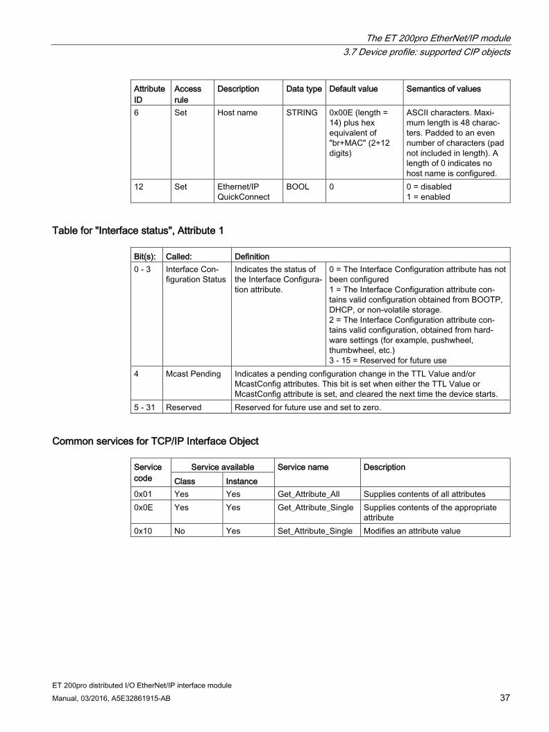
6 Set Host name STRING 0x00E (length = 14) plus hex equivalent of "br+MAC" (2+12 digits)
ASCII characters. Maxi-mum length is 48 charac-ters. Padded to an even number of characters (pad not included in length). A length of 0 indicates no host name is configured.
12 Set Ethernet/IP QuickConnect
BOOL 0 0 = disabled 1 = enabled
Table for "Interface status", Attribute 1 Bit(s): Called: Definition 0 - 3 Interface Con-
figuration Status Indicates the status of the Interface Configura-tion attribute.
0 = The Interface Configuration attribute has not been configured 1 = The Interface Configuration attribute con-tains valid configuration obtained from BOOTP, DHCP, or non-volatile storage. 2 = The Interface Configuration attribute con-tains valid configuration, obtained from hard-ware settings (for example, pushwheel, thumbwheel, etc.) 3 - 15 = Reserved for future use
4 Mcast Pending Indicates a pending configuration change in the TTL Value and/or McastConfig attributes. This bit is set when either the TTL Value or McastConfig attribute is set, and cleared the next time the device starts.
5 - 31 Reserved Reserved for future use and set to zero.
Common services for TCP/IP Interface Object Service code
Service available Service name Description Class Instance
0x01 Yes Yes Get_Attribute_All Supplies contents of all attributes 0x0E Yes Yes Get_Attribute_Single Supplies contents of the appropriate
attribute 0x10 No Yes Set_Attribute_Single Modifies an attribute value

The ET 200pro EtherNet/IP module 3.7 Device profile: supported CIP objects
ET 200pro distributed I/O EtherNet/IP interface module 38 Manual, 03/2016, A5E32861915-AB
3.7.5 EtherNet Link Object The EtherNet Link Object maintains link-specific counters and status information for an IEEE 802.3 communications interface. The ET 200pro EtherNet/IP has an embedded 2-port switch and has one instance of the EtherNet Link Object for the internally accessible interface.
Values set in Instance 1 Attribute 6 apply to both ports. Class attributes 1, 2, 3 Class services 0x1, 0xE, 0x10 Instance attributes 1, 2, 3, 6 Instance services 0x1, 0xE
Class attributes for EtherNet Link Object Attribute ID
Access rule
Name Description Data type Semantics of values
1 Get Revision Revision of this object UINT 1 = the minimum value. ≥ 2 = if instance attribute 6 is implemented. 3 = the maximum value.
2 Get Max In-stance
Maximum instance num-ber of an object currently created in this class level of the device
UINT The largest instance num-ber of a created object at this class hierarchy level.
3 Get Number of Instances
Number of object instanc-es currently created at this class level of the device
UINT The number of object in-stances at this class hier-archy level.

The ET 200pro EtherNet/IP module 3.7 Device profile: supported CIP objects
ET 200pro distributed I/O EtherNet/IP interface module Manual, 03/2016, A5E32861915-AB 39
Instance 1 attributes for EtherNet Link Object Attribute ID
Access rule
Name Description Data type Semantics of values
1 Get Interface Speed
Interface speed cur-rently in use
UDINT Speed in Mbps (10, 100, etc.).
2 Get Interface Flags
Interface status flags DWORD Bit map of interface flags. See Table "Interface Flags attribute" below.
3 Get Physical Address
MAC layer address ARRAY of 6 USINTs
MAC layer address in the format "XX-XX-XX-XX-XX-XX."
6 Set Interface Control
Configuration for physi-cal interface
STRUCT of:
See section "Interface Control" below.
Control Bits Interface Control Bits WORD ---- Forced Interface Speed
Speed at which the interface shall be forced to operate
UINT Speed in Mbps (10, 100, etc.).
Interface Flags attribute Bit(s): Called: Definition 0 Link Status Indicates whether the IEEE 802.3 communications interface is
connected to an active network: 0 = inactive link. 1 = active link. The determination of link status is implementation specific.
1 Half/Full Duplex Indicates the duplex mode currently in use: 0 = interface is running half duplex. 1 = interface is running full duplex. Note that if the Link Status flag is 0, the value of the half/full duplex flag is indeterminate.
2 - 4 Negotiation Status Indicates the status of link autonegotiation: 0 = autonegotiation in progress. 1 = autonegotiation and speed detection failed. Using default val-ues for speed and duplex. 2 = autonegotiation failed but detected speed. Duplex was faulted. 3 = successfully negotiated speed and duplex. 4 = autonegotiation not attempted. Forced speed and duplex.
5 Manual Setting Re-quires Reset
0 = interface can activate changes to link parameters (autonegoti-ate, duplex mode, interface speed) automatically. 1 = device requires a Reset service be issued to its Identity Object in order for the changes to take effect.
6 Local Hardware Fault 0 = interface detects no local hardware fault. 1 = local hardware fault detected.
7 - 31 Reserved Set to 0.

The ET 200pro EtherNet/IP module 3.7 Device profile: supported CIP objects
ET 200pro distributed I/O EtherNet/IP interface module 40 Manual, 03/2016, A5E32861915-AB
Interface Control attribute The Interface Control attribute is a structure consisting of Forced Interface Speed and Control Bits.
If the autonegotiate bit is 0, the Forced Interface Speed bits indicate the speed at which the interface operates. Speed is specified in megabits per second; for example, for 10 Mbps EtherNet, the Interface Speed is 10. Interfaces not supporting the requested speed return 0x09 (Invalid Attribute Value). If autonegotiation is enabled, attempting to set the Forced Interface Speed results in a response of 0x0C (Object State Conflict).
Control Bits operate as follows: Bit(s) Called: Definition 0 Autonegotiate 0 = 802.3 link autonegotiation is disabled.
1 = autonegotiation is enabled. If autonegotiation is disabled, the device uses the settings indicat-ed by the Forced Duplex Mode and Forced Interface Speed bits.
1 Forced Duplex Mode If the Autonegotiate bit is 0, the Forced Duplex Mode bit indicates whether the interface operates in full or half duplex mode. 0 = half duplex. 1 = full duplex. Interfaces not supporting the requested duplex return 0x09 (Invalid Attribute Value). If autonegotiation is enabled, attempting to set the Forced Duplex Mode bits results in a response of 0x0C (Object State Conflict).
Common services for EtherNet Link Object Service code
Need in implementation Service name Description Class Instance
0x01 Optional Optional Get_Attribute_All Supplies contents of all attrib-utes.
0x0E Conditional Required Get_Attribute_Single Supplies contents of the appro-priate attribute.
0x10 N/A Conditional Set_Attribute_Single Modifies a single attribute.

The ET 200pro EtherNet/IP module 3.8 Device profile: vendor-specific objects
ET 200pro distributed I/O EtherNet/IP interface module Manual, 03/2016, A5E32861915-AB 41
3.8 Device profile: vendor-specific objects
3.8.1 Adapter Object The Adapter Object provides the external configuration and monitoring interface to the ET 200pro EtherNet/IP. Class code 0x64 Class attributes No attributes are supported for the Adapter Object at the class level. Number of instances 1
Instance 1 attributes of the Adapter Object Attribute ID
Access rule Name Data type Data value
1 Get AdapterStatus USINT Adapter Status (see AdapterStatus details table).
2 Get InputSize USINT Currently configured input assembly size. 3 Get OutputSize USINT Currently configured output assembly size. 4 Get/Set 2 AutoConfig BOOL Automatic Configuration mode
1: Automatic configuration: the rack self-configures based on the modules installed (factory default). 0: Manual configuration: the rack configuration is stored in nonvolatile memory.
5 Get ConfigChanged BOOL True if manual configuration changes have been made but have not taken effect.
6 Get Diagnostic String Array of USINT [65]
An array of USINT containing slot diagnostics. The first byte of the array indicates the number of valid diagnostic bytes within the array (the remaining bytes within the array can be ig-nored).
7 Get ConfiguredSlots USINT Indicates the number of configured slot objects. 8 Get/Set 2 HeadParameters Array of USINT
[19] Configuration information for the adapter mod-ule.
9 Get/Set 2 IO_StatusEnable BOOL Enables the generation of an I/O status byte at the beginning of the input data I/O packet. Factory default = enabled.
10 Get/Set 2 HeadParamByte1 USINT Parameter bytes for electronic module and adapter module behavior. 11 Get/Set 2 HeadParamByte2 USINT
12 Get/Set 2 HeadParamByte3 USINT 13 Get/Set 2 HeadParamByte4 USINT 14 Get/Set 2 HeadParamByte5 USINT 15 Get/Set 2 HeadParamByte6 USINT 16 Get/Set 2 HeadParamByte7 USINT

The ET 200pro EtherNet/IP module 3.8 Device profile: vendor-specific objects
ET 200pro distributed I/O EtherNet/IP interface module 42 Manual, 03/2016, A5E32861915-AB
Attribute ID
Access rule Name Data type Data value
17 Get/Set 2 HeadParamByte8 USINT 18 Get/Set 2 HeadParamByte9 USINT 19 Get/Set 2 HeadParamByte10 USINT 20 Get/Set 2 HeadParamByte11 USINT 21 Get/Set 2 HeadParamByte12 USINT 22 Get/Set 2 HeadParamByte13 USINT 23 Get/Set 2 HeadParamByte14 USINT 24 Get/Set 2 HeadParamByte15 USINT 25 Get/Set 2 HeadParamByte16 USINT 26 Get/Set 2 HeadParamByte17 USINT 27 Get/Set 2 HeadParamByte18 USINT 28 Get/Set 2 HeadParamByte19 USINT 29 Reserved 30 Reserved 31 Reserved 32 Get Firmware version
String Length ASCII String
Struct of: USINT STRING
Firmware version
33 Get Serial Number String Length ASCII String
Struct of: USINT STRING
Serial number
1 Length of data [...] array does not include data. 2 When an I/O connection is open: setting this attribute returns Device_State_Conflict.
Attribute 1 [AdapterStatus] details Object 0x64 Instance 0x01 Attribute 0x06 Size 65
The AdapterStatus attribute reports the status of the ET 200pro EtherNet/IP and electronic modules: Bit(s) Name Description 0 Reserved 1 Parameters rejected One or more modules rejected the parameters
specified by its slot object. 2 Configuration rejected One or more modules rejected the configuration
byte specified by its slot object. 3 Electronic module diagnostics One or more modules is reporting an error. 4 - 7 Reserved

The ET 200pro EtherNet/IP module 3.8 Device profile: vendor-specific objects
ET 200pro distributed I/O EtherNet/IP interface module Manual, 03/2016, A5E32861915-AB 43

The ET 200pro EtherNet/IP module 3.8 Device profile: vendor-specific objects
ET 200pro distributed I/O EtherNet/IP interface module 44 Manual, 03/2016, A5E32861915-AB
Adapter Object: Standard diagnostic data Byte 0 Station state 1 Byte 1 Station state 2 Byte 2 Station state 3 Byte 3 Master address Byte 4 Ident number (low) Byte 5 Ident number (high)
The structure of the standard diagnostic data is as follows: Byte Bit(s) Description 0 0, 1 Not used
2 CfgFault: configuration data mismatch 3 ExtDiag: extended Diagnostic data available and valid 4 - 7 Not used
1 0 Not used 1 Bus error or > 16 modules 2 - 7 Not used
2 0 - 6 Not used 7 ExtDiagOverflow: extended diagnostic data overflow
3, 4, 5 Not used
Attribute 9 [IO_StatusEnable] details The IO_StatusEnable attribute enables/disables the generation of a single I/O status byte at the beginning of the input data I/O packet. This status byte indicates if any faults have occurred which would result in invalid data. The default value for Attribute 9 is enabled (1).
The format of the I/O status byte is shown below: 7 6 5 4 3 2 1 0 --- --- --- --- --- --- --- Fault
Attributes 10-28 [HeadParamByte(n)] details The HeadParamByte attributes provide single byte (USINT) access to the elements of the HeadParameters attribute (attribute 8) for access via tools not supporting complex data type representation. Modification of the HeadParameters will affect all the corresponding HeadParamByte attributes and vice versa.

The ET 200pro EtherNet/IP module 3.8 Device profile: vendor-specific objects
ET 200pro distributed I/O EtherNet/IP interface module Manual, 03/2016, A5E32861915-AB 45
Common services for the Adapter Object Service code
Implemented for Service name Class Instance
0x0E No Yes Get_Attribute_Single 0x10 No Yes Set_Attribute_Single
3.8.2 Slot Object The following information applies to the Slot Object for the ET 200pro EtherNet/IP module. The Slot Object provides the external configuration and monitoring interface to the I/O module in one slot. One instance of this object exists for each available slot. Class code 0x65 Class attributes No attributes are supported for the Slot Object at the class level. Number of instances 63
Instance attributes of the Slot Object Attribute ID
Access rule Name Data type Data value
1 Get / Set1,2 ModuleRefer-ence
UINT For Configuration Tool use.
2 Get / Set1,2 ParameterSize USINT Number of parameter bytes required by this slot (max. 32).
3 Get / Set1,2 Parameters Array of USINT
Parameter bytes for this slot: array size is set by Attribute 2.
4 Get / Set1,2 ConfigByte USINT Configuration byte for this slot. 5 Get SlotStatus USINT Slot status code (see Attribute 5 table). 6 Get Channel0Status USINT Channel Status code (see Attribute 6-13
table). 7 Get Channel1Status USINT 8 Get Channel2Status USINT 9 Get Channel3Status USINT 10 Get Channel4Status USINT 11 Get Channel5Status USINT 12 Get Channel6Status USINT 13 Get Channel7Status USINT

The ET 200pro EtherNet/IP module 3.8 Device profile: vendor-specific objects
ET 200pro distributed I/O EtherNet/IP interface module 46 Manual, 03/2016, A5E32861915-AB
Attribute ID
Access rule Name Data type Data value
14 Get Channel0Type USINT Channel Type code (see Attribute 14-21 ta-ble). The Channel Type code is zero if the corresponding Channel Status code is zero.
15 Get Channel1Type USINT 16 Get Channel2Type USINT 17 Get Channel3Type USINT 18 Get Channel4Type USINT 19 Get Channel5Type USINT 20 Get Channel6Type USINT 21 Get Channel7Type USINT 22 Get / Set1,2 ParamByte1 USINT Parameter bytes for this slot: Number actually
used is set by Attribute 2. 23 Get / Set1,2 ParamByte2 USINT 24 Get / Set1,2 ParamByte3 USINT 25 Get / Set1,2 ParamByte4 USINT 26 Get / Set1,2 ParamByte5 USINT 27 Get / Set1,2 ParamByte6 USINT 28 Get / Set1,2 ParamByte7 USINT 29 Get / Set1,2 ParamByte8 USINT 30 Get / Set1,2 ParamByte9 USINT 31 Get / Set1,2 ParamByte10 USINT 32 Get / Set1,2 ParamByte11 USINT 33 Get / Set1,2 ParamByte12 USINT 34 Get / Set1,2 ParamByte13 USINT 35 Get / Set1,2 ParamByte14 USINT 36 Get / Set1,2 ParamByte15 USINT 37 Get / Set1,2 ParamByte16 USINT 38 Get / Set1,2 ParamByte17 USINT 39 Get / Set1,2 ParamByte18 USINT 40 Get / Set1,2 ParamByte19 USINT 41 Get / Set1,2 ParamByte20 USINT 42 Get / Set1,2 ParamByte21 USINT 43 Get / Set1,2 ParamByte22 USINT 44 Get / Set1,2 ParamByte23 USINT 45 Get / Set1,2 ParamByte24 USINT 46 Get / Set1,2 ParamByte25 USINT 47 Get / Set1,2 ParamByte26 USINT 48 Get / Set1,2 ParamByte27 USINT 49 Get / Set1,2 ParamByte28 USINT 50 Get / Set1,2 ParamByte29 USINT 51 Get / Set1,2 ParamByte30 USINT 52 Get / Set1,2 ParamByte31 USINT 53 Get / Set1,2 ParamByte32 USINT
The ET 200pro EtherNet/IP module 3.8 Device profile: vendor-specific objects
ET 200pro distributed I/O EtherNet/IP interface module Manual, 03/2016, A5E32861915-AB 47
Attribute ID
Access rule Name Data type Data value
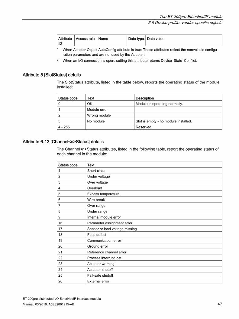
1 When Adapter Object AutoConfig attribute is true: These attributes reflect the nonvolatile configu-ration parameters and are not used by the Adapter.
2 When an I/O connection is open, setting this attribute returns Device_State_Conflict.
Attribute 5 [SlotStatus] details The SlotStatus attribute, listed in the table below, reports the operating status of the module installed: Status code Text Description 0 OK Module is operating normally. 1 Module error 2 Wrong module 3 No module Slot is empty - no module installed. 4 - 255 Reserved
Attribute 6-13 [Channel<n>Status] details The Channel<n>Status attributes, listed in the following table, report the operating status of each channel in the module: Status code Text 1 Short circuit 2 Under voltage 3 Over voltage 4 Overload 5 Excess temperature 6 Wire break 7 Over range 8 Under range 9 Internal module error 16 Parameter assignment error 17 Sensor or load voltage missing 18 Fuse defect 19 Communication error 20 Ground error 21 Reference channel error 22 Process interrupt lost 23 Actuator warning 24 Actuator shutoff 25 Fail-safe shutoff 26 External error

The ET 200pro EtherNet/IP module 3.8 Device profile: vendor-specific objects
ET 200pro distributed I/O EtherNet/IP interface module 48 Manual, 03/2016, A5E32861915-AB
Status code Text 27 Ambiguous error 28 Channel temporarily unavailable
Attribute 14-21 [Channel<n>Type] details The Channel<n>Type attributes, listed in the following table, provide additional detail when the corresponding Channel<n>Status is reporting an error. Status code Text Description 0 N/A Reported when corresponding Channel<n>Status is
reporting "No error" 1 Bit 1-bit channel 2 2 Bit 2-bit channel 3 4 Bit 4-bit channel 4 Byte 8-bit channel 5 Word 16-bit channel 6 2 Word 32-bit channel 7 - 255 Reserved
Attribute 22-53 [ParamByte(n)] details The ParamByte attributes provide single byte (USINT) access to the first 32 elements of the Parameters attribute (Attribute 3) for access via tools not supporting complex data type representation. Modification of the Parameters attribute will affect all the corresponding ParamByte attributes and vice versa. The maximum size for the slot object’s ParameterSize attribute is 32.
Common services for the Slot Object Service code
Implemented for Service name Class Instance
0x0E No Yes Get_Attribute_Single 0x10 No Yes Set_Attribute_Single

The ET 200pro EtherNet/IP module 3.9 Technical specifications
ET 200pro distributed I/O EtherNet/IP interface module Manual, 03/2016, A5E32861915-AB 49
3.9 Technical specifications SIMATIC interface module ET 200pro EtherNet/IP interface module: 2 EtherNet ports with M12 connectors; up to 1 m width connectable to a maximum of 16 power, electronic, or motor starter modules. SUPPLY VOLTAGE Rated 24 V Lower limit 20.4 V Upper limit 28.8 V INPUT CURRENT From supply voltage 1L+, max. 400 mA (dependent on con-
nection module, typ. POWER LOSSES Power loss, typ. 6 W ADDRESS AREA Addressing volume Outputs 255 bytes Inputs 255 bytes INTERFACES Supports protocol for EtherNet/IP Automatic detection of transmission speed Yes Transmission rate, max. 100 Mbps M12 (2 ports) Yes PROTOCOLS Supports protocol for EtherNet/IP Yes INTERRUPTS/DIAGNOSTICS/STATUS INFORMATION Diagnoses Diagnostic functions Yes Diagnostics indication LED Module Status, Network Status, and I/O Status
LEDs Yes
Monitoring 24 V voltage supply ON (green) Yes 24 VDC power LED Yes Connection to network P1 LINK (green) Yes Connection to network P2 LINK (green) Yes GALVANIC ISOLATION Between backplane bus and electronics No Between supply voltage and electronics No Between EtherNet and electronics Yes

The ET 200pro EtherNet/IP module 3.9 Technical specifications
ET 200pro distributed I/O EtherNet/IP interface module 50 Manual, 03/2016, A5E32861915-AB
DIMENSIONS Width 135 mm Height 130 mm Depth 59.3 mm WEIGHT Weight, approx. 490 g

ET 200pro distributed I/O EtherNet/IP interface module Manual, 03/2016, A5E32861915-AB 51
Installing, mounting, and connecting 4 4.1 Installing
Simple installation The ET 200pro distributed I/O system is designed for simple installation. The wide range of products available for the ET 200pro system give you many options for configuring your application.
Installation position The preferred installation position for the ET 200pro EtherNet/IP module is horizontal on a vertical wall. Any other installation position is also possible.
Installing on a rack You can preassemble your ET 200pro modules on a narrow or wide rack before you install the rack on your site.
For details on rack installation, see the "Rack" chapter of the SIMATIC ET 200pro distributed I/O system Operating Instructions manual. You can access the manual on the companion disk that shipped with your product. You can also access the manual on the Siemens Industry Online Support (https://support.automation.siemens.com/cs/?lc=en-US) website.
4.2 Mounting The ET 200pro EtherNet/IP interface module connects the ET 200pro system with EtherNet I/O and supplies power to the electronic modules.
Mounting details For details on mounting the ET 200pro EtherNet/IP module and other components of the ET 200pro system, see the "Mounting" chapter of the "SIMATIC ET 200pro distributed I/O system Operating Instructions" manual. You can access the manual on the companion disk that shipped with your product. You can also access the manual on the Siemens Industry Online Support (https://support.automation.siemens.com/cs/?lc=en-US) website.

Installing, mounting, and connecting 4.3 Connecting
ET 200pro distributed I/O EtherNet/IP interface module 52 Manual, 03/2016, A5E32861915-AB
4.3 Connecting There are connection guidelines that you must follow to ensure safe operation of the ET 200pro EtherNet/IP module and the ET 200pro system.
Connection details For details on connecting the ET 200pro EtherNet/IP module and other components of the ET 200pro system, see the "Connection" chapter of the "SIMATIC ET 200pro distributed I/O system Operating Instructions" manual. You can access the manual on the companion disk that shipped with your product. You can also access the manual on the Siemens Industry Online Support (https://support.automation.siemens.com/cs/?lc=en-US) website.

ET 200pro distributed I/O EtherNet/IP interface module Manual, 03/2016, A5E32861915-AB 53
Commissioning 5 5.1 Configuring the ET 200pro EtherNet/IP module
Use the EIP ET200 Configuration Tool to configure the ET 200pro EtherNet/IP module. Refer to the "EIP ET200 Configuration Tool User Reference Guide" for complete instructions.
5.2 Setting the IP address DHCP is the factory default. When the ET 200pro EtherNet/IP module is using DHCP, you can set IP addresses by using Microsoft Windows and Linux DHCP/BOOTP servers. There are several free servers for Microsoft Windows available for download from the Internet. Use discretion when downloading software from the Internet.
After you set the IP address with DHCP, you can then use the EIP ET200 Configuration Tool to set a permanent IP address and turn off DHCP. See the "EIP ET200 Configuration Tool User Reference Guide" for detailed instructions.

Commissioning 5.3 Grouping electronic modules
ET 200pro distributed I/O EtherNet/IP interface module 54 Manual, 03/2016, A5E32861915-AB
5.3 Grouping electronic modules
Introduction Grouping modules allows you to make better use of the available address range of the ET 200pro EtherNet/IP module and reduce the data exchange between the ET 200pro and the EtherNet/IP master.
You can achieve these benefits by grouping two digital output modules within one byte in the output area of the process image. Arrange the electronic modules systematically and label them accordingly.
The two digital output modules that you group must be of the same module type. You can insert other modules between the two modules that you have grouped.
You can use no more than 8 channels (1 byte) in total for grouping. The ET 200pro EtherNet/IP module has a maximum address space of 255 bytes for inputs and 255 bytes for outputs.
Configuration The ET 200pro system has address space of up to 255 bytes for inputs and 255 bytes for outputs. To better exploit the available address space of the scanner and reduce data transfer between the ET 200pro and the scanner, you can group several electronic modules/load feeders in a single byte in the input or output area of the process image. This is achieved by the systematic arrangement and designation of the ET 200pro electronic modules.
In Appendix C, you will find a table describing the address space required for the individual modules.
Procedure for groupable modules 1. In the hardware catalog of your configuration software, you can recognize groupable
modules by the fact that they are available in duplicate. The modules differ from each other only by a " * " in the designation.
2. Configure the ET 200pro setup, adhering to the following rules:
– The modules that you can group in a single byte must be of the same module type.
– There can be a total of no more than 8 channels (1 byte).
3. From the Configuration Tool hardware catalog, select a module without the " * " designation.
– Result: You open a byte and store the first module there.
4. From the Configuration Tool hardware catalog, select a module with the " * " designation.
– Result: In the open byte, you store additional modules until all the bits are occupied.
5. If a byte is filled, you must configure a module again (that is, open a new byte for a module without the " * ").

Commissioning 5.3 Grouping electronic modules
ET 200pro distributed I/O EtherNet/IP interface module Manual, 03/2016, A5E32861915-AB 55
Note
The EIP ET200 Configuration Tool does not check whether the modules have been grouped correctly. If you configure more than 8 channels in one byte, the modules that exceed the byte limit are reported as being incorrectly configured in the diagnosis:
Module status → 10B: Incorrect module; invalid user data
These modules are not addressed.
Note
ET 200pro assembles data on byte boundaries. Some scanners may only provide access to this data on word boundaries. You should organize your ET 200pro modules to conform to the scanner's restrictions. For example, configure the grouping of digital modules so that an analog module will occupy bytes 0 to 3 or 4 to 7. In this way, the analog modules will begin on even-byte boundaries to avoid an analog value being split between two words.

Commissioning 5.3 Grouping electronic modules
ET 200pro distributed I/O EtherNet/IP interface module 56 Manual, 03/2016, A5E32861915-AB
Examples of possible configurations are illustrated as follows:
Grouping modules in Automatic Configuration (default) mode

Commissioning 5.3 Grouping electronic modules
ET 200pro distributed I/O EtherNet/IP interface module Manual, 03/2016, A5E32861915-AB 57
Grouping modules in User-configured mode
No grouping If you do not want to group your digital output modules in a single byte, use only modules without the " * " designation in the Configuration Tool hardware catalog. Each electronic module will then occupy one byte in the process image.

Commissioning 5.4 Commissioning and startup
ET 200pro distributed I/O EtherNet/IP interface module 58 Manual, 03/2016, A5E32861915-AB
5.4 Commissioning and startup You commission the automation system according to your plant configuration. The procedure outlined below only describes the commissioning of ET 200pro connected to an EtherNet/IP master.
Requirements of ET 200pro on EtherNet/IP References to chapters in the following table are to the "SIMATIC ET 200pro distributed I/O system Operating Instructions" manual. You can access the manual on the companion disk that shipped with your product. You can also access the manual on the Siemens Industry Online Support (https://support.automation.siemens.com/cs/?lc=en-US) website.
For I/O controller actions, reference the manual that shipped with your I/O controller. Actions Reference ET 200pro is mounted Chapter "Mounting" ET 200pro is wired Chapter "Wiring" Device names are assigned to the I/O device Chapter "Configuring" ET 200pro is configured Chapter "Configuring" Supply voltage to the I/O controller is switched on I/O controller manual I/O controller is in RUN I/O controller manual
Commissioning the ET 200pro system 1. Switch on the electronic / encoder supply 1L+ for ET 200pro
2. Switch on the load voltage supply(ies) 2L+
Note Changes to the backplane bus
Always switch off power to the electronic / encoder supply 1L+ before you modify the backplane bus configuration (for example, changing the number of modules, removing the terminating module).
Commissioning the ET 200pro EtherNet/IP 1. Switch on the supply voltage for the module
2. Switch on the supply voltage for the load as necessary

Commissioning 5.5 Using QuickConnect
ET 200pro distributed I/O EtherNet/IP interface module Manual, 03/2016, A5E32861915-AB 59
5.5 Using QuickConnect
5.5.1 QuickConnect overview
What is QuickConnect™? QuickConnect technology enables EtherNet/IP devices to quickly power up and join an EtherNet/IP network. Examples of typical implementations might include the following:
A robotic application where a robot arm quickly exchanges tools to switch tasks.
A pallet application where a large frame consisting of many I/O modules moves down an assembly line and connects to different controllers at different locations on the line.
Connection time The ET200pro EtherNet/IP interface module is a Class B QuickConnect target device. Therefore, the module is able to power up, send the first gratuitous ARP packet, and be ready to accept a TCP connection in 2 seconds or less.
Advantages of using QuickConnect QuickConnect accelerates the startup of distributed I/O devices. It shortens the time that the respective configured distributed I/O devices require in order to reach the cyclic user data exchange in the following cases:
After distributed I/O devices have been activated.
After the supply voltage has returned.
After a station has returned.
Using QuickConnect reduces waiting times between the scheduled processes of a restart. This enables greater throughput in production by accelerating the production process using removable I/O devices.

Commissioning 5.5 Using QuickConnect
ET 200pro distributed I/O EtherNet/IP interface module 60 Manual, 03/2016, A5E32861915-AB
Architecture A QuickConnect system consists of two sides: a controller side and a tool side.
The controller side might include some of the following components:
Robot with a tool-changing coupler
Robot controller
Managed switch
EtherNet/IP communication modules
EtherNet/IP network
EtherNet/IP-based I/O devices
The tool side typically consists of multiple tools that include these components:
A tool-changing coupler
EtherNet/IP network
EtherNet/IP-based I/O devices with QuickConnect capability
5.5.2 Guidelines for using QuickConnect on your network
QuickConnect and the EIP ET200 Configuration Tool Use the EIP ET200 Configuration Tool to enable QuickConnect, to turn off autonegotiation, and to set a fixed baud rate and duplex.
Note that if QuickConnect is turned on in the ET 200pro EtherNet/IP module, you should not use the ET 200pro EtherNet/IP Configuration Tool to perform a firmware update because the self-checks are turned off in that mode.
Requirements An EtherNet/IP QuickConnect system requires an electrical lock signal. The electrical lock signal indicates that the tool changer has applied power to the tool. This is a hard-wired signal that must be implemented by the system builder. This signal must run from the tool changer back to the control system and must be connected to a digital input module. This signal is the event that starts the QuickConnect sequence.

Commissioning 5.5 Using QuickConnect
ET 200pro distributed I/O EtherNet/IP interface module Manual, 03/2016, A5E32861915-AB 61
QuickConnect system guidelines The following guidelines are required in order to enable setup with QuickConnect: System component Guidelines Tool side devices • Use a preconfigured, static IP address for the devices. This removes
DHCP/BOOTP cycle time. • Configure the devices for 100 Mbps, full-duplex operation in both the
switch and the end-node device. • Configure the devices to not autonegotiate and to not use Auto-MDIX. • Use straight-through EtherNet/IP cables on the devices. • Connect the devices in a linear topology. Ring topology is not supported.
Switches • Make sure an EtherNet/IP managed switch on the controller side re-mains powered on at all times. Only the tool side is subject to power cy-cling. This is important so that the switch does not block communication to and from devices.
Data • I/O data sizes must remain the same when nodes on a new device use the same IP address. If the I/O sizes are different, then the nodes need unique IP addresses.
Communication • A QuickConnect I/O device issues a gratuitous ARP message announc-ing its presence on the network. The module continues to issue the gra-tuitous ARP message every 25 ms for a maximum of 40 times (1 second) until an I/O connection is established.
• The module issues a TCP close when it receives a forward close mes-sage. Otherwise, connections may stay open for several seconds before they time out.
Controllers • Upon receiving the electrical lock signal, the controller waits for a mod-ule-specific delay period and then uninhibits the QuickConnect module to open an I/O connection.
• The controller knows the device startup time. You might need to alter the power-up time to delay the connection establishment procedure by that amount of time.

Commissioning 5.5 Using QuickConnect
ET 200pro distributed I/O EtherNet/IP interface module 62 Manual, 03/2016, A5E32861915-AB
QuickConnect sequence Using a robot system as an example:
1. The controller inhibits current connections to QuickConnect modules, and the robot arm physically disengages the current tool.
2. The robot arm physically attaches a new QuickConnect module.
3. The new QuickConnect module powers up.
4. The controller acknowledges a successful attachment to a new tool via an electrical lock signal.
5. Upon receiving the electrical lock signal, the controller waits for the devices to start up before uninhibiting a new set of I/O connections and then connects to the new QuickConnect module.
6. When all connections are established, the robot is ready for operation.
Procedures for using QuickConnect Port parameter Setting Negotiation Off Rate 100 Mbps Duplex Full Auto-MDIX Off
To enable the use of QuickConnect, perform the following steps:
1. Connect the ET 200pro EtherNet/IP module to a managed switch with the switch port set to autonegotiation off and auto crossover (auto-MDIX) off, with the same fixed baud rate and duplex as the device. You can use an EtherNet straight-through cable (1:1) by connecting to Port 2 on the ET 200pro EtherNet/IP module because Port 2 is crossed over internally. (A connection to Port 1 on the ET 200pro EtherNet/IP module would require a crossover cable). Another option is to have more than one ET 200pro module set up this way and connect them in a daisy chain with Port 2 of one device connected to Port 1 of the other. This can be done with straight-through cables.
2. Use the EIP ET200 Configuration Tool, turn autonegotiation off and set a fixed baud rate
and duplex.
3. Turn on QuickConnect with the Configuration Tool.

Commissioning 5.5 Using QuickConnect
ET 200pro distributed I/O EtherNet/IP interface module Manual, 03/2016, A5E32861915-AB 63
Wiring rules for disabled autonegotiation With auto crossover (MDIX) turned off, the ET 200pro EtherNet/IP ports are set as follows:
Port 1 - normal (straight-through) pin assignment
Port 2 - crossed over pin assignment
Crossed over pin assignment means that the pin assignment for the ports for sending and receiving between devices is exchanged internally.
5.5.3 Replacing a faulty QuickConnect Adapter In case of QuickConnect failure, follow this process to replace both the ET 200pro EtherNet/IP module and the connection module:
1. Prepare and mount the replacement modules.
2. Power up the replacement devices.
3. Configure the replacement module's IP address using DHCP, or set a fixed IP address with the EIP ET200 Configuration Tool.
4. Use the Configuration Tool to turn off autonegotiation, set a fixed baud rate and duplex, and turn QuickConnect on as described in the topic "Guidelines for using QuickConnect on your network".
The replacement module is now ready for QuickConnect power-up.
Note
If you are replacing only the ET200pro EtherNet/IP module and are not also replacing the connection module, you can skip steps 3 and 4 above because the configuration and network data is stored in the connection module's flash memory.

Commissioning 5.5 Using QuickConnect
ET 200pro distributed I/O EtherNet/IP interface module 64 Manual, 03/2016, A5E32861915-AB
5.5.4 Troubleshooting and optimization
Delayed connection time Many factors can cause the controller connection time to be slower than expected. These factors include the following:
RPI (I/O cycle time)
Time slice percentage
Timer set in the application logic
EtherNet/IP traffic
Controller task load
If you cannot achieve optimum connection time with the recommended settings, you may need to evaluate alternate EtherNet/IP configurations or controller requirements.
Timing errors Once you initially configure your system, you should test whether the connection timing is within your required timeframe. A QuickConnect I/O device issues a gratuitous ARP message on the network every 25 ms for a maximum of 40 times (1 second) until an I/O connection is established. If you experience periodic missed connections, it is recommended that you:
Analyze network traffic for the root cause.
Extend the timer in your application logic to a value greater than 650 ms if necessary.

Commissioning 5.6 Firmware updates
ET 200pro distributed I/O EtherNet/IP interface module Manual, 03/2016, A5E32861915-AB 65
5.6 Firmware updates You perform firmware updates by using the EIP ET200 Configuration Tool and EtherNet/IP. See the Configuration Tool User Reference Guide for detailed instructions.
Note
If QuickConnect is turned on in the ET 200pro EtherNet/IP module, you should not perform a firmware update with the Configuration Tool because the self-checks are turned off in that mode.

ET 200pro distributed I/O EtherNet/IP interface module Manual, 03/2016, A5E32861915-AB 66
General technical specifications 6 6.1 Standards and approvals
Contents of general technical specifications:
The standards and test values which the ET 200pro distributed I/O system complies with/satisfies
The test criteria used to test the ET 200pro distributed I/O system
Note
Information on the nameplate
You will find the current markings and approvals on the nameplate of the respective product.
CE approval
The ET 200pro distributed I/O system meets the requirements and protective objectives of the following EC directives, and satisfies the Harmonized European Standards (EN) for Programmable Logic Controllers which were published in the official pamphlets of the European Community:
2006/95/EC "Electrical Equipment Designed for Use within Certain Voltage Limits" (Low Voltage Directive)
2004/108/EC "Electromagnetic Compatibility Directive" (EMC Directive)
The EC Declarations of Conformity are made available to the relevant authorities at the following address:
Siemens AG Automation and Drives I IA AS R&D ST DH A Postfach 1963 D-92209 Amberg, Germany
These files are also available for download on the Customer Support Internet pages, keyword "Declaration of Conformity".

General technical specifications 6.1 Standards and approvals
ET 200pro distributed I/O EtherNet/IP interface module Manual, 03/2016, A5E32861915-AB 67
Approval
Underwriters Laboratories Inc. acc. to
UL 508 (Industrial Control Equipment)
CSA C22.2 No. 142 (Process Control Equipment)
Note
For the pneumatic interface module, no cULus approval has been applied for.
NEMA classification of ET 200pro (for the US market) The ET 200pro distributed I/O system conforms to the NEMA classification: Enclosure rating type: 4X indoor use only.
Marking for Australia and New Zealand
The ET 200pro distributed I/O system satisfies the requirements of the AS/NZS CISPR 16 standard.
IEC 61131 The ET 200pro distributed I/O system satisfies the requirements and criteria of IEC 61131-2 (Programmable Logic Controllers, Part 2: Equipment Requirements and Tests).
EtherNet/IP standard The ET 200pro EtherNet/IP module complies with EtherNet/IP Specification CIP Networks Library Volume 2: EtherNet/IP Adaption of CIP, Edition 1.12.
Use in industrial environments SIMATIC products are designed for use in industrial applications. Area of application Interference emission requirement Interference immunity requirement Industry EN 61000-6-4: 2007 EN 61000-6-2: 2005

General technical specifications 6.1 Standards and approvals
ET 200pro distributed I/O EtherNet/IP interface module 68 Manual, 03/2016, A5E32861915-AB
Use in residential areas
Note
The ET 200pro distributed I/O system is intended for use in industrial environments; when used in residential areas, it can affect radio/television reception.
If you use the ET 200pro in residential areas, you must ensure observance of the Class B radio interference limit in accordance with EN 55011 regarding the emission of radio interferences.
Suitable measures for achieving the required Class B radio interference level include, for example:
Installation of ET 200pro in grounded control cabinets/control boxes
Use of filters in the supply lines

General technical specifications 6.2 Electromagnetic compatibility
ET 200pro distributed I/O EtherNet/IP interface module Manual, 03/2016, A5E32861915-AB 69
6.2 Electromagnetic compatibility
Definition Electromagnetic compatibility refers to the capability of electrical equipment of reliably performing its dedicated function in an electromagnetic environment, without causing interference in the same environment.
The ET 200pro distributed I/O system meets all requirements of EMC legislation for the European market. This requires that the ET 200pro distributed I/O system complies with the requirements and guidelines for electrical installation.
Pulse-shaped interference The following table shows the electromagnetic compatibility of the ET 200pro distributed I/O system relative to pulse-shaped interference. Pulse-shaped interference Tested with Corresponds to degree
of severity Electrostatic discharge according to IEC 61000-4-2.
8 kV 6 kV
3 (air discharge) 3 (contact discharge)
Burst pulses (high-speed transi-ent interference) according to IEC 61000-4-4.
2 kV (supply line) 2 kV (signal line)
3 3
High-energy single pulse (surge) according to IEC 61000-4-5 Only with lightning protection elements
3
• Asymmetric coupling 2 kV (supply line) 2 kV (signal/data line)
• Symmetric coupling 1 kV (supply line) 1 kV (signal/data line)
Sinusoidal interference The table below shows the electromagnetic compatibility of the ET 200pro distributed I/O device with respect to sinusoidal interference.
HF interference according to IEC 61000-4-3 Electromagnetic HF field
HF coupling according to IEC 61000-4-6
Amplitude modulated 80 to 1000 MHz; 1.4 to 2 GHz 0.15 to 80 MHz 10 V/m 80% AM (1 kHz) 10 Vrms unmodulated 2 to 2.7 GHz 80% AM (1 kHz) 1 V/m at 80% AM (1 kHz) 150 Ω source impedance

General technical specifications 6.3 Shipping and storage conditions
ET 200pro distributed I/O EtherNet/IP interface module 70 Manual, 03/2016, A5E32861915-AB
Emission of radio interference Interference emission of electromagnetic fields in accordance with EN 55016: Limit Value Class A, Group 1 (measured at a distance of 10 m). Frequency Emitted interference from 30 to 230 MHz < 40 dB (µV/m)Q from 230 to 1000 MHz < 47 dB (µV/m)Q
6.3 Shipping and storage conditions
Shipping and storage conditions The ET 200pro distributed I/O system surpasses the IEC 61131-2 requirements for shipping and storage conditions. The specifications below apply to modules that are transported and stored in their original packaging. Type of condition Permissible range Free fall ≤ 1 m Temperature –40 °C to +70 °C Temperature change 20 K/h Barometric pressure 1080 hPa to 660 hPa (corresponds to an altitude of -
1000 m to 3500 m) Relative humidity 5% to 95%, without condensation

General technical specifications 6.4 Mechanical and climatic environmental conditions
ET 200pro distributed I/O EtherNet/IP interface module Manual, 03/2016, A5E32861915-AB 71
6.4 Mechanical and climatic environmental conditions
Climatic environmental conditions The following climatic environmental conditions apply (indoor use only): Environmental requirements Areas of application Remarks Temperature 0 °C to 55 °C * All mounting positions Temperature change 10 K/h - Relative humidity 5% to 100% with condensation Barometric pressure 1080 hPa to 795 hPa Corresponds to an altitude of -
1000 m to 2000 m Concentration of pollutants SO2: <0.5 ppm;
RH < 60%, no condensation H2S: <0.1 ppm; RH < 60%, no condensation
-
* The FESTO CPV10 and CPV14 valve terminals deviate from the specified operating temperature range of 0 to 55 °C. For the temperature operating range of FESTO valve terminals, refer to the cor-responding FESTO Operating Manuals.
Modules for use in the -25 °C to 55 °C temperature range The following modules support operation in the -25 °C to 55 °C temperature range (indoor use only): Designation Order number IM 154-3 PN High Feature with terminating module ZNX:EIP200PRO CM IM M12, 7/8" ZNX:EIP200PROCM1 PM-E DC 24V 6ES7148-4CA00-0AA0 PM-O DC 2x24V 6ES7148-4CA60-0AA0 CM PM Direct 6ES7194-4BC00-0AA0 CM PM ECOFAST 6ES7194-4BA00-0AA0 CM PM 7/8" 6ES7194-4BD00-0AA0 CM PM PP 6ES7194-4BE00-0AA0 CM PM-O PP 6ES7194-4BH00-0AA0 CM IO 4 x M12 6ES7194-4CA00-0AA0 CM IO 4 x M12P 6ES7194-4CA10-0AA0 CM IO 4 x M12 Inverse 6ES7194-4CA50-0AA0 CM IO 8 x M12 6ES7194-4CB00-0AA0 CM IO 8 x M12P 6ES7194-4CB10-0AA0 CM IO 8 x M12D 6ES7194-4CB50-0AA0 CM IO 8 x M8 6ES7194-4EB00-0AA0 CM IO 2 x M12 6ES7194-4FB00-0AA0 CM IO 1 x M23 6ES7194-4FA00-0AA0 8 DI DC 24V 6ES7141-4BF00-0AA0

General technical specifications 6.4 Mechanical and climatic environmental conditions
ET 200pro distributed I/O EtherNet/IP interface module 72 Manual, 03/2016, A5E32861915-AB
Designation Order number 16 DI DC 24V 6ES7141-4BH00-0AA0 4 DO DC 24V/2.0A 6ES7142-4BD00-0AA0 8 DO DC 24V/0.5A 6ES7142-4BF00-0AA0 8 DI DC 24V High Feature 6ES7141-4BF00-0AB0 4 DO DC 24V/2.0A High Feature 6ES7142-4BD00-0AB0 4 DI / 4 DO DC 24V/0.5A 6ES7143-4BF50-0AA0 4 DIO / 4 DO DC 24V/0.5A 6ES7143-4BF00-0AA0 4 AI U High Feature 6ES7144-4FF00-0AB0 4 AI U High Feature 6ES7144-4FF01-0AB0 4 AI I High Feature 6ES7144-4GF00-0AB0 4 AI I High Feature 6ES7144-4GF01-0AB0 4 AI RTD High Feature 6ES7144-4JF00-0AB0 4 AI TC High Feature 6ES7144-4PF00-0AB0 4 AO U High Feature 6ES7145-4FF00-0AB0 4 AO I High Feature 6ES7145-4GF00-0AB0
Mechanical environmental conditions The table below shows the mechanical environmental conditions in the form of sinusoidal oscillation.
Modules Frequency range Continuous Infrequent Interface, electronic, and connection modules; Pneumatic interface modules with FESTO valve terminals
5 ≤ f ≤ 8 Hz 15 mm amplitude - 8 ≤ f ≤ 150 Hz 5 g constant acceleration 10 g constant acceleration

General technical specifications 6.4 Mechanical and climatic environmental conditions
ET 200pro distributed I/O EtherNet/IP interface module Manual, 03/2016, A5E32861915-AB 73
Testing mechanical environmental conditions The table below provides information about the type and scope of mechanical environmental condition tests.
Condition tested Test standard Interface, electronic, and connection modules;
Pneumatic interface modules with FESTO valve terminals Vibrations Vibration test accord-
ing to IEC 60068-2-6 Type of vibration: Frequency sweeps with a rate of change of 1 octave/minute. 5 Hz ≤ f ≤ 12 Hz, constant amplitude 15 mm 12 Hz ≤ f ≤ 150 Hz, constant acceleration 10 g Duration of vibration: 10 frequency sweeps per axis in each of three perpendicular axes
Shock Shock, tested accord-ing to IEC 60068-2-27
Type of shock: half-sine Shock intensity: 30 g peak value, 18 ms duration Direction of shock: 3 shock tests in +/- direction in each of the 3 perpendicular axes
Continuous shock Shock, tested accord-ing to IEC 60068-29
Type of shock: half-sine Shock intensity: 25 g peak value, 6 ms duration Direction of shock: 1000 shock tests in +/- direction at each of the 3 perpendicular axes

General technical specifications 6.5 Specifications for insulation tests, protection class, degree of protection, and rated voltage
ET 200pro distributed I/O EtherNet/IP interface module 74 Manual, 03/2016, A5E32861915-AB
6.5 Specifications for insulation tests, protection class, degree of protection, and rated voltage
Test voltage The proof of dielectric strength is provided in a type test with the following test voltage according to IEC 61131-2: Circuits with rated voltage Ve against other circuits or ground.
Test voltage
< 50 V 500 VDC < 150 V 2500 VDC < 250 V 4000 VDC
Pollution degree/overvoltage category according to IEC 61131-2 Pollution degree 2
Overvoltage category
– At Vr = 24 VDC: II
Degree of protection IP65 Degree of protection according to IEC 60529
Protection against the ingress of dust and full touch protection
Water projected by a nozzle against the enclosure from any direction shall have no harmful effect.
Degrees of protection IP66 and IP67 Degree of protection according to IEC 60529
Protection against the ingress of dust and full touch protection
IP66: Water from heavy seas or water projected in powerful jets shall not enter the enclosure in harmful quantities.
IP67: Protection against water when enclosure is immersed at specified pressures over a specified time period (water must not enter the enclosure in any harmful amount)
Rated voltage for operation The ET 200pro distributed I/O system operates at the following rated voltage and corresponding tolerance: Rated voltage Tolerance range 24 VDC 20.4 VDC to 28.8 VDC

General technical specifications 6.5 Specifications for insulation tests, protection class, degree of protection, and rated voltage
ET 200pro distributed I/O EtherNet/IP interface module Manual, 03/2016, A5E32861915-AB 75

ET 200pro distributed I/O EtherNet/IP interface module Manual, 03/2016, A5E32861915-AB 76
Order number A
Designation Order number ET 200pro EtherNet/IP interface module package ZNX:EIP200PRO CM IM M12, 7/8" connection module ZNX:ET200PROCM1

ET 200pro distributed I/O EtherNet/IP interface module Manual, 03/2016, A5E32861915-AB 77
Dimension drawing B
ET 200pro EtherNet/IP interface module front and side views

ET 200pro distributed I/O EtherNet/IP interface module Manual, 03/2016, A5E32861915-AB 78
Address area C
Address area of the modules The following table shows the address area for ET 200pro digital input and output modules: Module Address space of the inputs Address space of the outputs
Without group-ing
With grouping1 Without group-ing
With grouping1
Digital input modules 1 byte (8 DI) --- ---
--- 2 bytes (16 DI)
Digital output modules --- --- 1 byte (4 DO) 4 bits (4 DO) 1 byte (8 DO) ---
Digital input/output mod-ules
1 byte (4 DI) 4 bits (4 DI) 1 byte (4 DO) 4 bits (4 DO)
Analog input modules 4 bytes --- --- Analog output modules --- --- 4 bytes Direct-on-line starter 1 byte 4 bits 1 byte 4 bits Reversing starter 1 byte 4 bits 1 byte 4 bits 1 See the topic "Configuring the ET 200pro system"

ET 200pro distributed I/O EtherNet/IP interface module Manual, 03/2016, A5E32861915-AB 79
Index

ET 200pro distributed I/O EtherNet/IP interface module Manual, 03/2016, A5E32861915-AB 80
A Adapter Object, 41 AdapterStatus, 41 Address area, 49, 78 Address space, 14, 54 Approvals
CE, 66 CSA, 67
Assembly Object, 32 AutoConfig attribute, 41 Automatic Configuration mode, 19, 41 Autonegotiate, 40
B Burst pulses, 69 Bus length, 14 Bus module, 12
C CE
Approval, 66 Channel<n>Status, 47 Channel<n>Type, 48 ChannelStatus, 45 ChannelType, 46 Climatic environmental conditions, 71 Close Requests, 34 Coding element, 24 Commissioning, 58 ConfigByte, 45 ConfigChanged, 41 ConfiguredSlot, 41 Connecting, 52 Connection Manager Object, 34 Connection module, 13 Connection time, 59 Continuous shock, 73 Control Bits, 39, 40 CSA
Approval, 67
D Definition
Electromagnetic compatibility, 69 Degree of protection IP65, 74 Degree of protection IP66, 74 Degree of protection IP67, 74
Device_State_Conflict, 47 Diagnostic String, 41 Diagnostics, 49 Dimension drawings, 77 Dimensions, 50 Distributed I/O systems, 9 Domain name, 36 Duplex mode, 39, 40
E Electrical lock signal, 60 Electromagnetic compatibility, 69 Electrostatic discharge, 69 EMC, 69 Emission of radio interference, 70 ET 200pro distributed I/O system, 9 Ethernet Link Object, 38 EtherNet/IP standard, 67
F Fault
communication, 25 configuration, 23 electronic modules, 23 hardware, 39 recoverable, 30 unrecoverable, 30
Faulty module replacement, 28 Features and benefits, 16 Firmware updates, 65 Forced Interface Speed, 40

Index
ET 200pro distributed I/O EtherNet/IP interface module Manual, 03/2016, A5E32861915-AB 81
G Galvanic isolation, 49 Gateway address, 36 Grouping electronic module data, 21 Grouping modules, 54
Automatic Configuration mode, 56 User-configured mode, 57
H HeadParameters, 41 Host name, 37 Hot swapping, 24
I I/O features, 15 I/O status byte, 20, 44 Identity Object, 29 IEC 61131, 67 Illustration
ET 200pro EtherNet/IP module, 15 Input current, 49 Insulation test, 74 Interface
support, 49 Interface capability flags, 35 Interface Control, 39 Interface control flags, 35 Interface speed, 39 Interface Speed, 39 Interface status, 35 IO_StatusEnable, 20, 23, 41 IP address, 36
L LED status indicators, 17, 26 Link Status, 39
M MAC address, 39 Major unrecoverable fault, 31 Manual Setting, 39 Marking for Australia and New Zealand, 67 McastConfig, 37 Mechanical environmental conditions, 72 Module replacement using QuickConnect, 63 ModuleReference, 45
Motor starters, 19 Mounting, 51
N Negotiation Status, 39 Network mask, 36 Notes
byte boundaries, 55 Major Unrecoverable Fault, 31 modules exceeding byte limit, 55
O Objects
Adapter, 41 Assembly, 32 Connection Manager, 34 Ethernet Link, 38 Identity, 29 Slot, 45 TCP/IP Interface, 35
Open Requests, 34 Operating modes, 19 Order number, 14 Outgoing module, 13 Overvoltage category, 74
P Packing, 14 ParamByte, 46 ParamByte(n), 48 Parameter
channel-related diagnostics, 22 identifier-related diagnostics, 22 operation for ref. <> actual conf., 22 option handling, 23 submodule status, 22
Parameter assignment, 22 Parameter length
maximum, 14 ParameterSize, 45 Physical address, 39 Pollution degree, 74 Power loss, 49 Power module, 13 Power removal behavior, 21 Protection class, 74 Protocol
support, 49

Index
ET 200pro distributed I/O EtherNet/IP interface module 82 Manual, 03/2016, A5E32861915-AB
Pulse-shaped interference, 69
Q QuickConnect, 37, 59
R Rack, 12 Rated voltage, 74 Recyclability, 6 Reset behavior, 21
S Sensors, 19 Server, 36 Setting the IP address, 20, 53 Shipping conditions, 70 Shock, 73 Sinusoidal interference, 69 Slot Object, 45 SlotStatus, 45, 47 Storage conditions, 70
T TCP/IP Interface Object, 35 Technical specifications, 49
Electromagnetic compatibility, 69 Mechanical environmental conditions, 71
Terminating module, 12 Test voltage, 74 Timeout behavior, 21 Troubleshooting, 26
delayed connection time, 64 timing errors, 64
U Ungrounded reference potential, 14 User-configured mode, 20
V Vibrations, 73
W Weight, 50 Width
allowable, 14

Index
ET 200pro distributed I/O EtherNet/IP interface module Manual, 03/2016, A5E32861915-AB 83