estimation of angles from upper and lower limbs for
TRANSCRIPT

Estimation of Angles from Upper and Lower
Limbs for Recognition of Human Gestures
using Wireless Inertial Sensors
Irvin Hussein Lopez Nava, Angelica Munoz-Melendez
Technical Report No. CCC-15-004
December, 2015
Computational Sciences Coordination
Instituto Nacional de Astrofısica, Optica y Electronica
Tonantzintla, Puebla, Mexico
c⃝INAOE 2015All rights reserved
The author hereby grants to INAOE permission to reproduce and to distribute copiesof this Ph.D. research proposal in whole or in part
Estimation of Angles from Upper and Lower Limbs for Recognition ofHuman Gestures using Wireless Inertial Sensors
Irvin Hussein Lopez-Nava Angelica Munoz-Melendez
Computer Science DepartmentNational Institute of Astrophysics, Optics and Electronics
Luis Enrique Erro # 1, Santa Marıa Tonantzintla, Puebla, 72840, MexicoE-mail: {hussein,munoz}@inaoep.mx
Abstract
Human motion analysis is defined as any procedure involving any means for obtaining a quantitativeor qualitative measure of it. Quantitative analysis involves the measurement of biomechanical variables,such as pressure distribution, temporal gait parameters, among others, whereas qualitative analysis hasbeen defined as the systematic observation and introspective judgment of the quality of human movementfor the purpose of providing the most appropriate intervention to improve performance. In this researchwe are interested in the former analysis. Continuous monitoring of human motion in daily environmentprovides valuable and complementary information to that obtained in laboratory tests. Also, the humanmotion analysis helps the specialist and/or researcher in the field to obtain a quantitative assessment ofmotion parameters of the patients. Calculating variables about human motion using wearable inertialsensors is possible by applying computational techniques for information fusion, but it poses considerablechallenges such as data processing of multiple sensor readings from human soft tissue. Therefore, in thisPhD research proposal we propose to use angles between segments of upper and lower opposite limbs, asthe unit of measure to characterize human movements, because they are less sensitive to the particularitiesof persons, such as height, weight, gender and age. Our approach can be synthesized as follows. First,angles of segments and joints of human limbs will be estimated. Second, postures from sets of angles will beidentified. Third, human gestures will be classified from series of postures. Finally, identified gestures willbe validated in applications of serious games in daily living environments.
Keywords
Human motion analysis, inertial and magnetic sensors, estimation of angles, human gesture classification,daily living environments.
1

Contents
1 Introduction 31.1 Research Problem . . . . . . . . . . . . . . . . . . . . . . . . . . . . . . . . . . . . . . . . 31.2 Motivation . . . . . . . . . . . . . . . . . . . . . . . . . . . . . . . . . . . . . . . . . . . . 4
2 Background 52.1 Relevant concepts . . . . . . . . . . . . . . . . . . . . . . . . . . . . . . . . . . . . . . . . 52.2 Human anatomy concepts . . . . . . . . . . . . . . . . . . . . . . . . . . . . . . . . . . . . 6
2.2.1 Anatomical planes . . . . . . . . . . . . . . . . . . . . . . . . . . . . . . . . . . . 62.2.2 Movements of the limbs . . . . . . . . . . . . . . . . . . . . . . . . . . . . . . . . 6
2.3 Related work . . . . . . . . . . . . . . . . . . . . . . . . . . . . . . . . . . . . . . . . . . 72.3.1 Sensors . . . . . . . . . . . . . . . . . . . . . . . . . . . . . . . . . . . . . . . . . 92.3.2 Measuring motion unit . . . . . . . . . . . . . . . . . . . . . . . . . . . . . . . . . 102.3.3 Sensor fusion algorithms . . . . . . . . . . . . . . . . . . . . . . . . . . . . . . . . 112.3.4 System used for the evaluation . . . . . . . . . . . . . . . . . . . . . . . . . . . . . 12
2.4 Critical analysis . . . . . . . . . . . . . . . . . . . . . . . . . . . . . . . . . . . . . . . . . 13
3 Objectives 143.1 Research questions . . . . . . . . . . . . . . . . . . . . . . . . . . . . . . . . . . . . . . . 143.2 General and specific objectives . . . . . . . . . . . . . . . . . . . . . . . . . . . . . . . . . 143.3 Contributions . . . . . . . . . . . . . . . . . . . . . . . . . . . . . . . . . . . . . . . . . . 15
4 Methodology 16
5 Preliminary results 235.1 Description . . . . . . . . . . . . . . . . . . . . . . . . . . . . . . . . . . . . . . . . . . . 23
5.1.1 Flexion/extension . . . . . . . . . . . . . . . . . . . . . . . . . . . . . . . . . . . . 235.1.2 Pronation/supination . . . . . . . . . . . . . . . . . . . . . . . . . . . . . . . . . . 235.1.3 Algorithm . . . . . . . . . . . . . . . . . . . . . . . . . . . . . . . . . . . . . . . . 24
5.2 Evaluation . . . . . . . . . . . . . . . . . . . . . . . . . . . . . . . . . . . . . . . . . . . . 255.2.1 Measurement instruments . . . . . . . . . . . . . . . . . . . . . . . . . . . . . . . 255.2.2 Experimental settings . . . . . . . . . . . . . . . . . . . . . . . . . . . . . . . . . . 265.2.3 Subjects and conditions . . . . . . . . . . . . . . . . . . . . . . . . . . . . . . . . 26
5.3 Analysis of results . . . . . . . . . . . . . . . . . . . . . . . . . . . . . . . . . . . . . . . . 275.3.1 Discussion . . . . . . . . . . . . . . . . . . . . . . . . . . . . . . . . . . . . . . . 28
6 Plan of work 296.1 Activities of the work plan . . . . . . . . . . . . . . . . . . . . . . . . . . . . . . . . . . . 29
6.1.1 Activities that are finished . . . . . . . . . . . . . . . . . . . . . . . . . . . . . . . 296.1.2 Activities in progress . . . . . . . . . . . . . . . . . . . . . . . . . . . . . . . . . . 306.1.3 Future work . . . . . . . . . . . . . . . . . . . . . . . . . . . . . . . . . . . . . . . 31
6.2 Schedule . . . . . . . . . . . . . . . . . . . . . . . . . . . . . . . . . . . . . . . . . . . . . 32
2

1 Introduction
1.1 Research Problem
“Human motion analysis is defined as any procedure involving any means for obtaining a quantitativeor qualitative measure of it” [1].
Quantitative analysis involves the measurement of biomechanical variables, such as pressure distribu-tion, temporal gait parameters, human posture, among others. Because of the huge amount of data, thisanalysis requires computer-based processing [2]. In contrast, qualitative analysis has been defined as the“systematic observation and introspective judgment of the quality of human movement for the purpose ofproviding the most appropriate intervention to improve performance” [3]. In this research we are interestedin the quantitative analysis of human motion.
Calculating biomechanical variables from wearable inertial sensors is possible by using computationaltechniques for information fusion. From the calculated variables, it is possible to determine positions of thelimbs, and even recognize certain human gestures.
This research proposes to use angles between segments of upper and lower opposite limbs, as the unit ofmeasure to characterize human movements, because they are less sensitive to the particularities of persons[4], such as height, weight, gender and age, in contrast to other measures such as relative position or opticalflow of limbs. Also, this research proposes the calculation of these angles using only wearable sensors, thatcan be easily worn and carried by people in daily scenarios.
The techniques to be developed in this research involve significant computational challenges:
• The lack of accurate global reference. In contrast to methods relying on fixed sensors, when usingwearable sensors we do not have an accurate and invariant reference. That means that we have toincorporate in our methods a calibration phase in which an initial reference is established and then,constantly updated.
• The need of local estimations as a direct consequence of previous challenge. Not having a uniqueglobal reference means that all the calculations have to be estimated locally. That means that we haveto develop techniques inexpensive enough for the microprocessors embedded in wearable sensors.
• The need of a prompt response. Since these technologies are used in applications of human-computer interaction in daily scenarios, an important requirement is the time response. That meansthat is necessary to develop a system capable of producing an appropriate output in real time [5].
• The need of a more refined analysis. Several techniques for determining human activity based onwireless devices have been proposed. However, these techniques score a reasonable good performancewhen determining which activity makes a person, but not the way as such activity is realized. Thelatter is relevant for rehabilitation interfaces and exergames, for instance, and for determining howwell or badly an activity is done [6].
• The importance to consider anatomical constraints. In most of works the motion angles are es-timated with some restrictions or considering less degrees of freedom allowed to a segment or joint.More accurate estimations, such as orientation of the complex shoulder joint, are needed for a morerefined analysis of human motion than current estimations [7].
3

1.2 Motivation
The human motion analysis helps the specialist and/or researcher in the field to obtain a quantitative as-sessment of motion parameters of the patients. Measuring body movements accurately is crucial to identifyabnormal neuromuscular control, biomechanical disorders and injury prevention1.
Specialized systems, such as Vicon [8] or Optotrak [9], have a high accuracy when operating in controlledenvironments, e.g. several fixed cameras calibrated and correlated in a specific place following a specificcapturing configuration. These systems can provide a large amount of redundant data. Ambulatory systems,such as those using a Kinect [10] to capture human motion, are set in relatively uncontrolled environmentsand have a restricted field of view. These systems have a restricted margin of maneuverability and areintended for indoor use mainly. In contrast, wearable sensors have the advantage of being portable andsuitable for outdoor environments. These systems are arranged with respect to an anatomical reference ofthe human body to measure specific biomechanical variables or motion patterns.
Continuous monitoring of human motion in daily environment provides valuable and complementaryinformation to that obtained in laboratory tests. However, it has been extremely difficult to go beyond thelaboratory and obtain accurate measurements of human physical activity in daily life environments [11].
Develop and implement ambulatory and wearable systems is important to reach a larger population andmore complex scenarios than current systems for motion analysis.
The ultimate incentive of this research is to generate knowledge to enhance human-computer interaction,namely for applications oriented to the promotion of active aging, such as rehabilitation applications, seriousgames or exergames, and strengthening the social network of elderly, that can be used in daily care centers,retirement houses, and homes, for instance.
Our approach can be synthesized as follows. First, angles of segments and joints of human limbs will beestimated. Second, postures from sets of angles will be identified. Third, human gestures will be classifiedfrom series of postures. Finally, identified gestures will be validated in rehabilitation applications, such asserious games2, and in daily living scenarios.
As preliminary results, an algorithm to estimate angles from wireless inertial and magnetic sensors wastested for pronation/supination and flexion/extension human movements of 10 test subjects. Two sensingdevices were evaluated using an optical system as reference instrument in an experimental setting designedfor this experiment. According to the obtained results we conclude that it is feasible to implement methodsfor representing accurately human movements from wearable sensors.
1http://www.inr.gob.mx/i17.htm, accessed: Dec 1, 20142Serious games are games that are have been designed with a primary focus other than entertainment [12] and in principle they
could be used to construct novel forms of cognitive assessment [13] and for physical function rehabilitation purposes [14]
4
2 Background
2.1 Relevant concepts
In this section important concepts for the research are presented.Angle“An ‘angle with vertex A’ is a point A together with two distinct non-opposite rays
��!AB and
�!AC (called
the sides of the angle) emanating from A” [15]; we use the notation ^A for this angle.Sensing deviceThe term sensing device describes any encapsulated unit that may contain one or more of the following
sensors: accelerometer, gyroscope or magnetometer; as well as additional components such as batteries,communication modules, micro-processors and so on, arranged to jointly operate.
IMUAn inertial measurement unit, or IMU, “is an electronic device that measures linear acceleration, angular
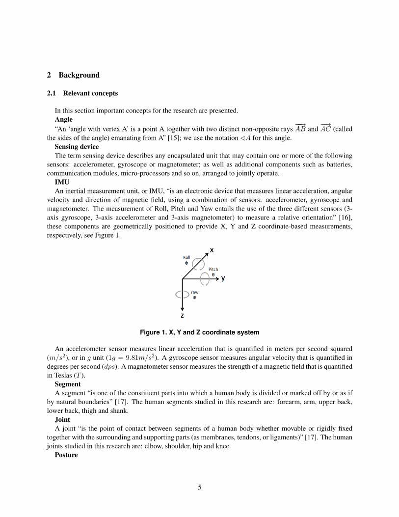
velocity and direction of magnetic field, using a combination of sensors: accelerometer, gyroscope andmagnetometer. The measurement of Roll, Pitch and Yaw entails the use of the three different sensors (3-axis gyroscope, 3-axis accelerometer and 3-axis magnetometer) to measure a relative orientation” [16],these components are geometrically positioned to provide X, Y and Z coordinate-based measurements,respectively, see Figure 1.
Figure 1. X, Y and Z coordinate system
An accelerometer sensor measures linear acceleration that is quantified in meters per second squared(m/s2), or in g unit (1g = 9.81m/s2). A gyroscope sensor measures angular velocity that is quantified indegrees per second (dps). A magnetometer sensor measures the strength of a magnetic field that is quantifiedin Teslas (T ).
SegmentA segment “is one of the constituent parts into which a human body is divided or marked off by or as if
by natural boundaries” [17]. The human segments studied in this research are: forearm, arm, upper back,lower back, thigh and shank.
JointA joint “is the point of contact between segments of a human body whether movable or rigidly fixed
together with the surrounding and supporting parts (as membranes, tendons, or ligaments)” [17]. The humanjoints studied in this research are: elbow, shoulder, hip and knee.
Posture
5

A posture is a representation of human limbs angles and describes the orientation of the joints in whichthe wearable inertial system is setting. To describe a posture given a time frame a pose vector is used:Ptx
= {^E,^S,^K,^H}, and represents elbow, shoulder, knee and hip angle, respectively.GestureA gesture “is a movement of part of the body to express an idea or meaning” [Oxford English Dictionary,
2014]. We use the term gesture to represent an action consisting of a succession of movements of the upperand lower limbs, that can be defined as: G = (P
t
)tnt=1 = {P
t1 , Pt2 , Pt3 , ..., Ptn}, where Ptx
is a posture in atime frame. In this study the gestures can be divided into the following categories: simple actions, trainingexercises and sports activities.
Real-time“A real-time system demands that the signal processing time, t
p
, must be less than the sampling period,T , in order to complete the processing task before the new sample comes in. That is: t
p
+ to
< T where to
is the overhead of I/O operations” [18]. In our approach a sampling rate of 50 Hz is considered.
2.2 Human anatomy concepts
Human anatomy is the setting (structure) in which the events (functions) of life occur. The three mainapproaches for studying anatomy are regional, systemic, and clinical (or applied), reflecting the body’sorganization and the priorities and purposes for studying it. Regional anatomy or topographical anatomyconsiders the organization of the human body as major parts or segments (see Figure 2): a main body,consisting of the head, neck, and trunk (subdivided into thorax, abdomen, back, and pelvis/perineum), andpaired upper limbs and lower limbs [19].
2.2.1 Anatomical planes
Anatomical descriptions are based on four imaginary planes (median, sagittal, frontal, and transverse) thatintersect the body in the anatomical position (see Figure 3):
• The median plane (median sagittal plane), the vertical plane passing longitudinally through the body,divides the body into right and left halves. The plane defines the midline of the head, neck, and trunkwhere it intersects the surface of the body.
• Sagittal planes are vertical planes passing through the body parallel to the median plane.
• Frontal planes are vertical planes passing through the body at right angles to the median plane, divid-ing the body into anterior (front) and posterior (back) parts.
• Transverse planes are horizontal planes passing through the body at right angles to the median andfrontal planes, dividing the body into superior (upper) and inferior (lower) parts.
2.2.2 Movements of the limbs
Most movements are defined with reference to the anatomical position, with movements occurring withinand around axes aligned with respect to specific anatomical planes (See Figure 4). Terms of movement mayalso be considered in pairs of opposite movements:
• Flexion and extension movements generally occur in sagittal planes around a transverse axis (SeeFigures 4 a & b).
6

Figure 2. Major parts of the body and regions (segments) of the upper and lower limbs [19]
• Abduction and adduction movements generally occur in a frontal plane around an anteroposterior axis(See Figure 4 c).
• Rotation involves turning or revolving a part of the body around its longitudinal axis (See Figure 4 c).
2.3 Related work
Wearable inertial (i.e. accelerometers or gyroscopes) and magnetic (i.e. magnetometer) sensors havebeen used in some clinical applications. Figure 5 depicts a taxonomy introduced in this work based on theapplication of researches in the field of human motion analysis. The first class corresponds to works focusedon measuring movements of a specific segment of the human body, such as the limbs. The outcome ofthese systems can be a common unit of measurement such as angles, for instance. The second class groupsworks whose outcome is based on an interpretation or high-level classification of human movements, suchas “running” or “walking”.
In the first class of our taxonomy works focused on measurements based on the human regional anatomyor topographical anatomy [19] are considered. Common examples are upper, lower or multiple limbs, aswell as other regions such as the head, neck and trunk.
Studies included in the second category are too diverse and comprise the estimation of spatio-temporalgait parameters and assessment of gait abnormalities [20], the recognition of meaningful human expressions
7
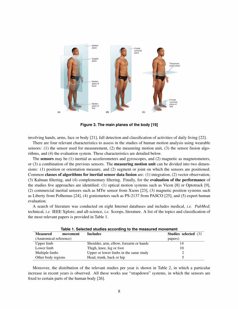
Figure 3. The main planes of the body [19]
involving hands, arms, face or body [21], fall detection and classification of activities of daily living [22].There are four relevant characteristics to assess in the studies of human motion analysis using wearable
sensors: (1) the sensor used for measurement, (2) the measuring motion unit, (3) the sensor fusion algo-rithms, and (4) the evaluation system. These characteristics are detailed below.
The sensors may be (1) inertial as accelerometers and gyroscopes, and (2) magnetic as magnetometers,or (3) a combination of the previous sensors. The measuring motion unit can be divided into two dimen-sions: (1) position or orientation measure, and (2) segment or joint on which the sensors are positioned.Common classes of algorithms for inertial sensor data fusion are: (1) integration, (2) vector observation,(3) Kalman filtering, and (4) complementary filtering. Finally, for the evaluation of the performance ofthe studies five approaches are identified: (1) optical motion systems such as Vicon [8] or Optotrack [9],(2) commercial inertial sensors such as MTw sensor from Xsens [23], (3) magnetic position systems suchas Liberty from Polhemus [24], (4) goniometers such as PS-2137 from PASCO [25], and (5) expert humanevaluation.
A search of literature was conducted on eight Internet databases and includes medical, i.e. PubMed;technical, i.e. IEEE Xplore; and all-science, i.e. Scoops, literature. A list of the topics and classification ofthe most relevant papers is provided in Table 1.
Table 1. Selected studies according to the measured movementMeasured movement(Anatomical reference)
Includes Studies selected (31papers)
Upper limb Shoulder, arm, elbow, forearm or hands 14Lower limb Thigh, knee, leg or foot 10Multiple limbs Upper or lower limbs in the same study 2Other body regions Head, trunk, back or hip 5
Moreover, the distribution of the relevant studies per year is shown in Table 2, in which a particularincrease in recent years is observed. All these works use “strapdown” systems, in which the sensors arefixed to certain parts of the human body [26].
8

(a) Flexion and extension ofupper limb at shoulder jointand lower limb at hip joint
(b) Flexion and extension offorearm at elbow joint and ofleg at knee joint
(c) Abduction and adduction of rightlimbs and rotation of left limbs atshoulder and hip joints, respectively
Figure 4. Movements of the limbs and segments of the limbs [19]
Figure 5. Taxonomy of Human Motion Analysis using wearable sensors
The relevant articles that were analyzed are distributed as follows: 45% focuses on measuring upper limbmovements only, 39% focuses on measuring lower limb movements only; 6% measure movements of both,upper and lower limbs simultaneously; and 10% measure movements of other anatomical references, suchas head or trunk.
2.3.1 Sensors
There are two levels of analysis of sensors used in these works, the first one concerns the type of sensor usedto estimate human motion: accelerometer, gyroscope, magnetometer or a combination of them. The secondlevel concerns the composition of modules used for acquiring motion parameters in a sensing device. Thereader should remind that, the term sensing device describes any encapsulated unit that may contain oneor more of the previously cited sensors, as well as additional components such as batteries, communicationmodules, micro-processors and so on, arranged to jointly operate, see Figure 6.
9
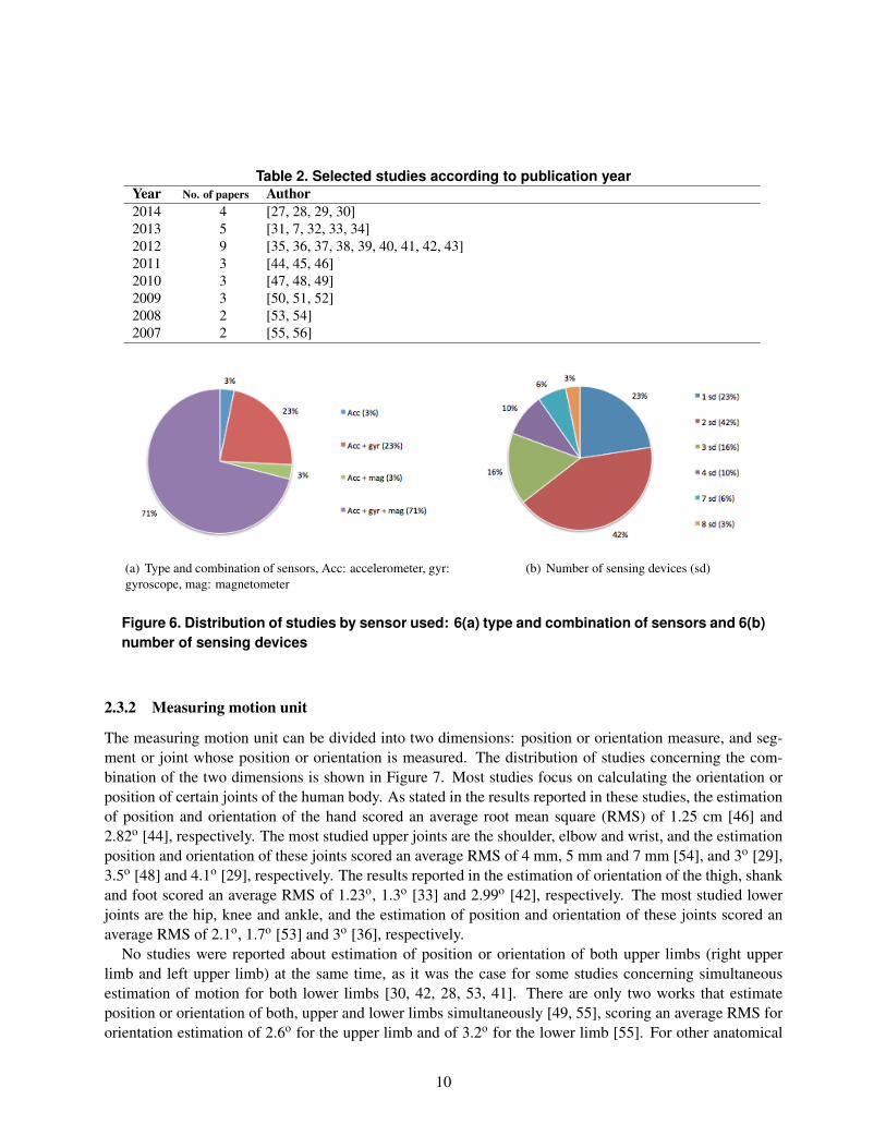
Table 2. Selected studies according to publication yearYear No. of papers Author2014 4 [27, 28, 29, 30]2013 5 [31, 7, 32, 33, 34]2012 9 [35, 36, 37, 38, 39, 40, 41, 42, 43]2011 3 [44, 45, 46]2010 3 [47, 48, 49]2009 3 [50, 51, 52]2008 2 [53, 54]2007 2 [55, 56]
(a) Type and combination of sensors, Acc: accelerometer, gyr:gyroscope, mag: magnetometer
(b) Number of sensing devices (sd)
Figure 6. Distribution of studies by sensor used: 6(a) type and combination of sensors and 6(b)number of sensing devices
2.3.2 Measuring motion unit
The measuring motion unit can be divided into two dimensions: position or orientation measure, and seg-ment or joint whose position or orientation is measured. The distribution of studies concerning the com-bination of the two dimensions is shown in Figure 7. Most studies focus on calculating the orientation orposition of certain joints of the human body. As stated in the results reported in these studies, the estimationof position and orientation of the hand scored an average root mean square (RMS) of 1.25 cm [46] and2.82o [44], respectively. The most studied upper joints are the shoulder, elbow and wrist, and the estimationposition and orientation of these joints scored an average RMS of 4 mm, 5 mm and 7 mm [54], and 3o [29],3.5o [48] and 4.1o [29], respectively. The results reported in the estimation of orientation of the thigh, shankand foot scored an average RMS of 1.23o, 1.3o [33] and 2.99o [42], respectively. The most studied lowerjoints are the hip, knee and ankle, and the estimation of position and orientation of these joints scored anaverage RMS of 2.1o, 1.7o [53] and 3o [36], respectively.
No studies were reported about estimation of position or orientation of both upper limbs (right upperlimb and left upper limb) at the same time, as it was the case for some studies concerning simultaneousestimation of motion for both lower limbs [30, 42, 28, 53, 41]. There are only two works that estimateposition or orientation of both, upper and lower limbs simultaneously [49, 55], scoring an average RMS fororientation estimation of 2.6o for the upper limb and of 3.2o for the lower limb [55]. For other anatomical
10
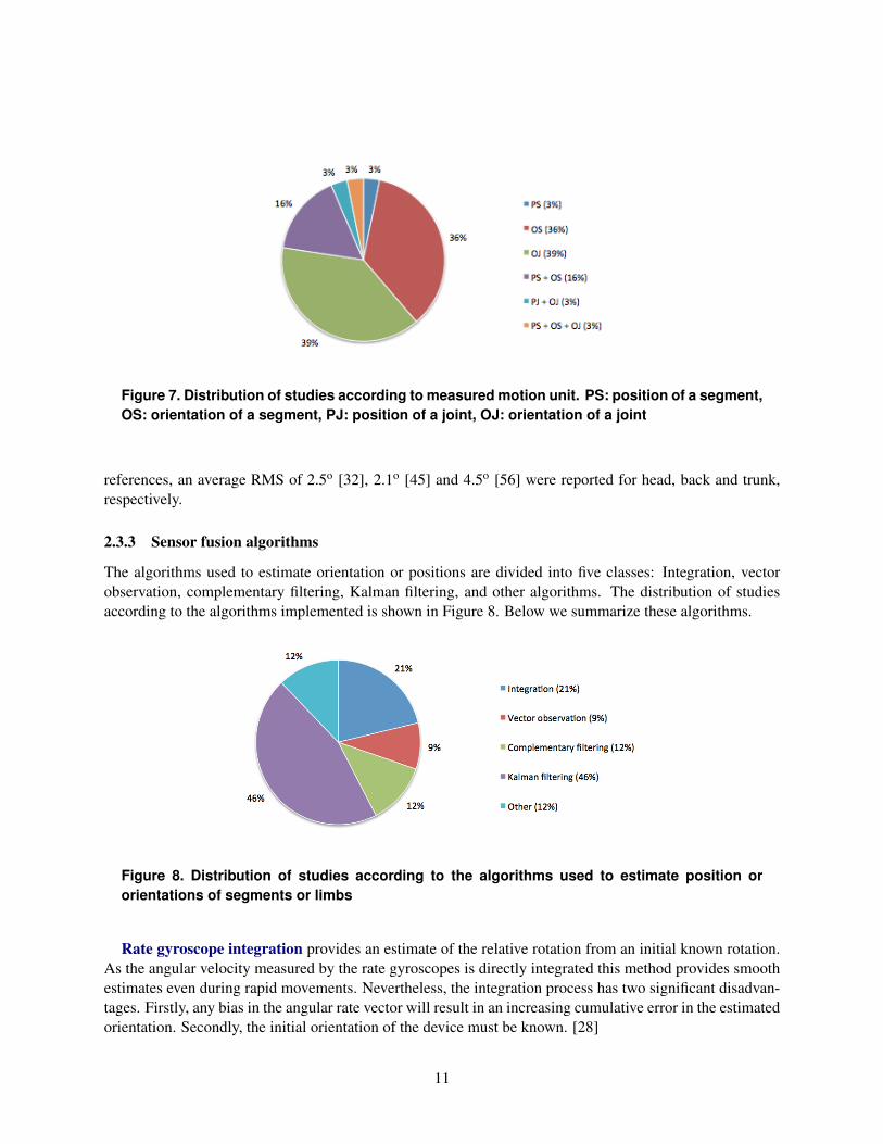
Figure 7. Distribution of studies according to measured motion unit. PS: position of a segment,OS: orientation of a segment, PJ: position of a joint, OJ: orientation of a joint
references, an average RMS of 2.5o [32], 2.1o [45] and 4.5o [56] were reported for head, back and trunk,respectively.
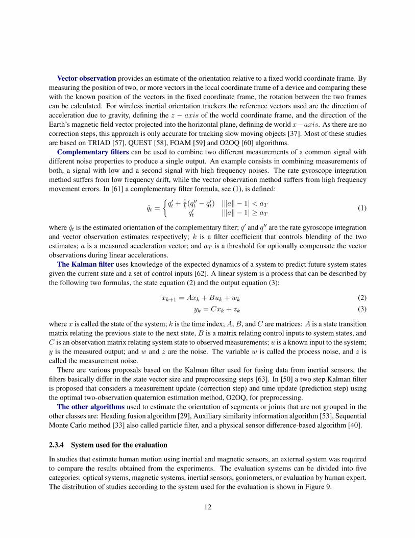
2.3.3 Sensor fusion algorithms
The algorithms used to estimate orientation or positions are divided into five classes: Integration, vectorobservation, complementary filtering, Kalman filtering, and other algorithms. The distribution of studiesaccording to the algorithms implemented is shown in Figure 8. Below we summarize these algorithms.
Figure 8. Distribution of studies according to the algorithms used to estimate position ororientations of segments or limbs
Rate gyroscope integration provides an estimate of the relative rotation from an initial known rotation.As the angular velocity measured by the rate gyroscopes is directly integrated this method provides smoothestimates even during rapid movements. Nevertheless, the integration process has two significant disadvan-tages. Firstly, any bias in the angular rate vector will result in an increasing cumulative error in the estimatedorientation. Secondly, the initial orientation of the device must be known. [28]
11
Vector observation provides an estimate of the orientation relative to a fixed world coordinate frame. Bymeasuring the position of two, or more vectors in the local coordinate frame of a device and comparing thesewith the known position of the vectors in the fixed coordinate frame, the rotation between the two framescan be calculated. For wireless inertial orientation trackers the reference vectors used are the direction ofacceleration due to gravity, defining the z � axis of the world coordinate frame, and the direction of theEarth’s magnetic field vector projected into the horizontal plane, defining de world x�axis. As there are nocorrection steps, this approach is only accurate for tracking slow moving objects [37]. Most of these studiesare based on TRIAD [57], QUEST [58], FOAM [59] and O2OQ [60] algorithms.
Complementary filters can be used to combine two different measurements of a common signal withdifferent noise properties to produce a single output. An example consists in combining measurements ofboth, a signal with low and a second signal with high frequency noises. The rate gyroscope integrationmethod suffers from low frequency drift, while the vector observation method suffers from high frequencymovement errors. In [61] a complementary filter formula, see (1), is defined:
qt
=
⇢q0t
+ 1k
(q00t
� q0t
) |kak � 1| < aT
q0t
|kak � 1| � aT
(1)
where qt
is the estimated orientation of the complementary filter; q0 and q00 are the rate gyroscope integrationand vector observation estimates respectively; k is a filter coefficient that controls blending of the twoestimates; a is a measured acceleration vector; and a
T
is a threshold for optionally compensate the vectorobservations during linear accelerations.
The Kalman filter uses knowledge of the expected dynamics of a system to predict future system statesgiven the current state and a set of control inputs [62]. A linear system is a process that can be described bythe following two formulas, the state equation (2) and the output equation (3):
xk+1 = Ax
k
+Buk
+ wk
(2)yk
= Cxk
+ zk
(3)
where x is called the state of the system; k is the time index; A, B, and C are matrices: A is a state transitionmatrix relating the previous state to the next state, B is a matrix relating control inputs to system states, andC is an observation matrix relating system state to observed measurements; u is a known input to the system;y is the measured output; and w and z are the noise. The variable w is called the process noise, and z iscalled the measurement noise.
There are various proposals based on the Kalman filter used for fusing data from inertial sensors, thefilters basically differ in the state vector size and preprocessing steps [63]. In [50] a two step Kalman filteris proposed that considers a measurement update (correction step) and time update (prediction step) usingthe optimal two-observation quaternion estimation method, O2OQ, for preprocessing.
The other algorithms used to estimate the orientation of segments or joints that are not grouped in theother classes are: Heading fusion algorithm [29], Auxiliary similarity information algorithm [53], SequentialMonte Carlo method [33] also called particle filter, and a physical sensor difference-based algorithm [40].
2.3.4 System used for the evaluation
In studies that estimate human motion using inertial and magnetic sensors, an external system was requiredto compare the results obtained from the experiments. The evaluation systems can be divided into fivecategories: optical systems, magnetic systems, inertial sensors, goniometers, or evaluation by human expert.The distribution of studies according to the system used for the evaluation is shown in Figure 9.
12

Figure 9. Distribution of studies according to the system used for comparison
In most of the revised studies optical motion systems were used as reference to evaluate the performanceof each study. The optical systems that are more commonly used for comparison were [8] and [9] systems.
Regarding the configuration of the experiments, the mean age of the test subjects is 26.25 years (± 5.17),indicating a clear trend to test the systems and methods only with young people. Other population groupssuch as people with mobility problems have not been considered in tests so far.
2.4 Critical analysis
Human motion analysis is effectively a niche opportunity that poses challenging issues for multidisci-plinary research. An open issue for engineers is to investigate proper configurations and arrangementsof sensors capable of operating in daily environments, as well as methods for self-calibration and self-correction, two areas in which we have identified a lack of literature and research. In the field of computerscience, there is a constant need for algorithms able to estimate the position and orientation of upper andlower limbs in real-time simultaneously using local devices mainly.
Finally, it is necessary to investigate methods and technologies for dealing with complex joints involvingseveral degrees of freedom (DOF), such as the shoulder and hip. Characterizing the movement of these partsof the body is necessary for recognizing a broader range of human gestures and for enhancing high-levelclassification of human motion.
13
3 Objectives
The human motion analysis helps the specialist and/or researcher in the field to obtain a quantitativeassessment of motion parameters of the patients. Measuring body movements accurately is necessary forapplications of human-computer interaction such as rehabilitation interfaces or serious games [64].
This research proposes to use angles between segments of upper and lower opposite limbs, as the unit ofmeasure to characterize human movements because they are less sensitive to changes in anatomy [4], usinginertial/magnetic sensors.
3.1 Research questions
This research intends to answer the research questions introduced below.
• How to estimate an angle of a non-static segment of the upper and lower limbs of the human bodywith respect to an anatomical plane using local information obtained from a sensing device, such asan inertial measurement unit?
• How to estimate an angle of a non-static joint of the upper and lower limbs of the human body, usinglocal information obtained from two sensing devices located on contiguous segments to the joint?
• How to combine at least four joint angles, from upper and lower limbs, merging information froma wearable inertial and magnetic system comprising several sensing devices in order to determine aposture at a given time?
• How to classify human gestures from a set of postures in a period of time for daily living environ-ments?
3.2 General and specific objectives
The general objective of this research is:
Development of algorithms for real-time estimation of angles at upper and lower limbs, using a wearableinertial system for characterization of human motion in daily environments.
The specific objectives are:
• Implement an algorithm to estimate an angle of upper or lower limb segments, using informationobtained from a sensing device aligned with respect to an anatomical plane
• Develop an algorithm to estimate an angle of upper or lower limb joint, using information obtainedfrom two sensing devices placed on contiguous segments of the joint.
• Develop an algorithm to estimate postures combining at least four angles of upper and lower limbsmerging information from an wearable inertial system.
• Propose a method to classify human gestures from sequences of postures of upper and lower humanlimbs for daily living environments.
14

3.3 Contributions
The main contributions of this research are summarized below:
• An algorithm to estimate joint angles of the upper and lower limbs using inertial/magnetic sensors.
• An algorithm for real-time estimation of postures from a wearable inertial/magnetic system using theprevious calculated angles.
• A method to classify human gestures based on the estimated sequences of postures for daily livingenvironments.
• Datasets of controlled experiments conducted in this study.
15
4 Methodology
In this section, the methods and techniques for achieving our goals are summarized.
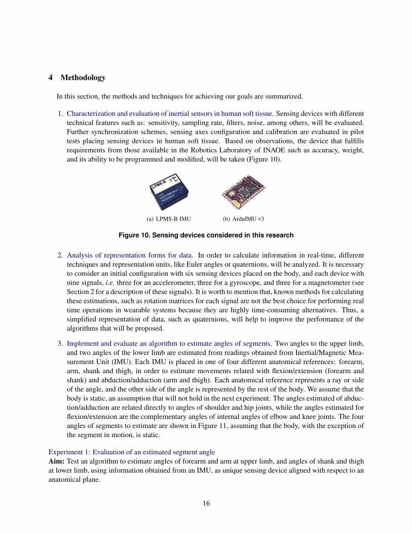
1. Characterization and evaluation of inertial sensors in human soft tissue. Sensing devices with differenttechnical features such as: sensitivity, sampling rate, filters, noise, among others, will be evaluated.Further synchronization schemes, sensing axes configuration and calibration are evaluated in pilottests placing sensing devices in human soft tissue. Based on observations, the device that fulfillsrequirements from those available in the Robotics Laboratory of INAOE such as accuracy, weight,and its ability to be programmed and modified, will be taken (Figure 10).
(a) LPMS-B IMU (b) ArduIMU v3
Figure 10. Sensing devices considered in this research
2. Analysis of representation forms for data. In order to calculate information in real-time, differenttechniques and representation units, like Euler angles or quaternions, will be analyzed. It is necessaryto consider an initial configuration with six sensing devices placed on the body, and each device withnine signals, i.e. three for an accelerometer, three for a gyroscope, and three for a magnetometer (seeSection 2 for a description of these signals). It is worth to mention that, known methods for calculatingthese estimations, such as rotation matrices for each signal are not the best choice for performing realtime operations in wearable systems because they are highly time-consuming alternatives. Thus, asimplified representation of data, such as quaternions, will help to improve the performance of thealgorithms that will be proposed.
3. Implement and evaluate an algorithm to estimate angles of segments. Two angles to the upper limb,and two angles of the lower limb are estimated from readings obtained from Inertial/Magnetic Mea-surement Unit (IMU). Each IMU is placed in one of four different anatomical references: forearm,arm, shank and thigh, in order to estimate movements related with flexion/extension (forearm andshank) and abduction/adduction (arm and thigh). Each anatomical reference represents a ray or sideof the angle, and the other side of the angle is represented by the rest of the body. We assume that thebody is static, an assumption that will not hold in the next experiment. The angles estimated of abduc-tion/adduction are related directly to angles of shoulder and hip joints, while the angles estimated forflexion/extension are the complementary angles of internal angles of elbow and knee joints. The fourangles of segments to estimate are shown in Figure 11, assuming that the body, with the exception ofthe segment in motion, is static.
Experiment 1: Evaluation of an estimated segment angleAim: Test an algorithm to estimate angles of forearm and arm at upper limb, and angles of shank and thighat lower limb, using information obtained from an IMU, as unique sensing device aligned with respect to ananatomical plane.
16

(a) Angle of forearm ^f (b) Angle of arm ^a
(c) Angle of shank ^s (d) Angle of thigh ^t
Figure 11. Angles of segments to estimate in Experiment 1
H1: It is possible to calculate angles of segments of the body limbs from the combined signals of anaccelerometer, a magnetometer and a gyroscope, with an RMSE of 10%.Experimental design:
• Experimental unit: segment of human body
• Factor: position of segment to measure
• Treatment: configuration of initial and final position of the segment
Variables:
• Independent: AccX, AccY, AccZ (3D linear acceleration), GyrX, GyrY, GyrZ (3D angular velocity),MagX, MagY, MagZ (direction of magnetic field in 3D)
• Dependent: an angle ^forearm, ^arm, ^shank, ^thigh
• Controlled: position of sensors and segments with respect to anatomical planes
17
Potential sources of bias:
• Information bias: internal and external rotation, adduction, abduction, flexion or extension movementsthat are not being evaluated. Possible solution: constraint of the segment to measure
Evaluation:
• The experiment will be evaluated according to these measures: error and correlation coefficient be-tween the proposal and an optical system used as reference.
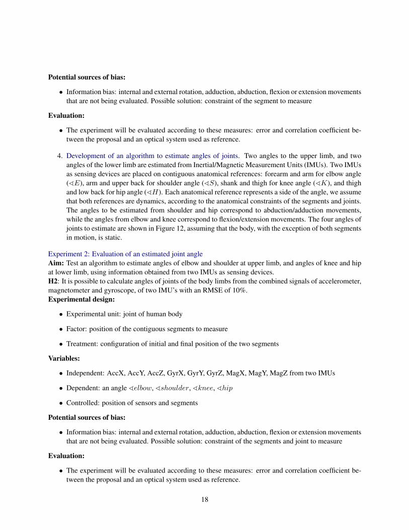
4. Development of an algorithm to estimate angles of joints. Two angles to the upper limb, and twoangles of the lower limb are estimated from Inertial/Magnetic Measurement Units (IMUs). Two IMUsas sensing devices are placed on contiguous anatomical references: forearm and arm for elbow angle(^E), arm and upper back for shoulder angle (^S), shank and thigh for knee angle (^K), and thighand low back for hip angle (^H). Each anatomical reference represents a side of the angle, we assumethat both references are dynamics, according to the anatomical constraints of the segments and joints.The angles to be estimated from shoulder and hip correspond to abduction/adduction movements,while the angles from elbow and knee correspond to flexion/extension movements. The four angles ofjoints to estimate are shown in Figure 12, assuming that the body, with the exception of both segmentsin motion, is static.
Experiment 2: Evaluation of an estimated joint angleAim: Test an algorithm to estimate angles of elbow and shoulder at upper limb, and angles of knee and hipat lower limb, using information obtained from two IMUs as sensing devices.H2: It is possible to calculate angles of joints of the body limbs from the combined signals of accelerometer,magnetometer and gyroscope, of two IMU’s with an RMSE of 10%.Experimental design:
• Experimental unit: joint of human body
• Factor: position of the contiguous segments to measure
• Treatment: configuration of initial and final position of the two segments
Variables:
• Independent: AccX, AccY, AccZ, GyrX, GyrY, GyrZ, MagX, MagY, MagZ from two IMUs
• Dependent: an angle ^elbow, ^shoulder, ^knee, ^hip
• Controlled: position of sensors and segments
Potential sources of bias:
• Information bias: internal and external rotation, adduction, abduction, flexion or extension movementsthat are not being evaluated. Possible solution: constraint of the segments and joint to measure
Evaluation:
• The experiment will be evaluated according to these measures: error and correlation coefficient be-tween the proposal and an optical system used as reference.
18

(a) Angle of elbow ^E (b) Angle of shoulder ^S
(c) Angle of knee ^K (d) Angle of hip ^H
Figure 12. Angles of segments to estimate in Experiment 2
5. Development of algorithm to estimate postures of upper and lower limbs. The postures are estimatedcombining the four joint angles obtained previously involving anatomical constraints with respect toan upper and the opposite lower limb at the same time. Remind that, a posture is a representation ofthe orientation of the joints in which the Wearable Inertial/Magnetic System is setting in a time unitPtx
= {^Etx
,^Stx
,^Ktx
,^Htx
}, and represents elbow, shoulder, knee and hip angles, respectively.The Wearable Inertial/Magnetic System comprises six Inertial/Magnetic Measurement Units (IMUsas sensing devices) placed on six anatomical references: forearm, arm and upper back for upperlimb joint angles (^Elbow,^Shoulder) and shank, thigh and low back for lower limb joint angles(^Knee,^Hip). In Figure 13 the distribution of IMUs on the named anatomical references and aposture from the joint angles estimated are shown.
Experiment 3: Estimation of a posture of upper and lower limbsAim: Test an algorithm to combine angles of elbow and shoulder at upper limb, and angles of knee and hipat lower limb, using information obtained from a Wearable Inertial/Magnetic System comprising six sensingdevices in order to estimate a posture in a time frame.H3: It is possible to estimate a posture from four joint angles of human opposite limbs combining infor-mation of six Inertial/Magnetic Measurement Units (IMUs) with a sampling rate less than one frame persecond.
19

Figure 13. Postures from a Wearable Inertial/Magnetic System
Experimental design:
• Experimental unit: joints of human body
• Factor: position of the six segments to measure
• Treatment: configuration of initial and final position of the six segments
Variables:
• Independent: four angles: ^elbow,^shoulder,^knee,^hip
• Dependent: a posture in a time frame Ptx
• Controlled: position of sensors and segments
Potential sources of bias:
• Information bias: internal and external rotation, adduction, abduction, flexion or extension movementsthat are not being evaluated. Possible solution: constraint of the segments and joints to measure
Evaluation:
• The experiment will be evaluated according to these measures: error and correlation coefficient be-tween the proposal and an specialized optical system, such as Vicon system, used as reference.
6. Method to classify human gestures using postures for daily living environments. With the estimatedpostures, a classification model from various human gestures, applying classification techniques suchas Hidden Markov Models (HMM), will be created. Remind that, a gesture is an action performed
20

by a succession of movements or postures of the upper and lower limbs, and can be represent as:G = (P
t
)tnt=1 = {P
t1 , Pt2 , Pt3 , ..., Ptn}, where P is a posture in a time frame. The configuration ofthe wearable inertial system for this stage is to place sensors on opposite limbs, i.e., measuring themovement of the right upper limb and the movement of the left lower limb simultaneously. In thefirst validation, the movements of upper limbs and the movements of lower limbs will be classifiedseparately, due the anatomical characteristics of the limb movements. The movements or gestures ofupper limbs to classify are related with Functional Range of Motion of the shoulder and elbow [65],and are listed bellow:
(a) Place the hand behind the neck
(b) Reach behind the back
(c) Touch the opposite shoulder
(d) Raise the arm up
The movements or gestures of lower limbs to classify are related to deambulation and are importantfor the human daily activities [66], as listed bellow:
(a) Walking
(b) Running
(c) Ascending stairs
(d) Descending stairs
(e) Sitting
(f) Standing
For a second validation (external validation) an application on real domain will be prepared. For that,the proposed method and algorithms might be applied in a human-computer interaction domain, likerehabilitation, serious games or interaction on virtual-environments, and might be evaluated usingusability metrics for Human Computer Interaction (HCI) and by clinical tests of experts of motionanalysis of the National Institute of Rehabilitation.
During 2015 two internships in foreign institutions in which the developed algorithms will be appliedhave been programmed. These applications include the calculation of angles for human motion ofpeople with mobility problems (in the framework of a joint project with colleagues from BogaziciUniversity in Istanbul, Turkey) as well as for the calculation of human gait parameters (in the frame-work of a joint project with colleagues from Universidad de Castilla-La Mancha in Ciudad Real,Spain). These internships shall enrich our research and will not compromise the achievement of ourgoals.
Experiment 4: Classification of human gestures for upper and lower limbsAim: Test an algorithm to classify human gestures from sequences of postures in comparison to relatedwork.H4: It is possible to classify human gestures using sequences of postures, with joint angles of an upper limbin conjunction with joint angles of the opposite lower limb, with an accuracy of 90%.Experimental design:
21

• Experimental unit: person with no report of mobility problems considering some age groups
• Factor: position of the six segments to measure
• Treatment: configuration of positions and velocity of the six segments
Variables:
• Independent: series of postures of two opposite limbs {Pt1 , Pt2 , Pt3 , ..., Ptn}
• Dependent: human gesture G = (Pt
)tnt=1
• Controlled: position of sensors and segments
Potential sources of bias:
• Information bias: internal and external rotation, adduction, abduction, flexion or extension of jointsthat are not being evaluated. Possible solution: constraint of the segments and joints of upper andlower limbs
Validation:
• The experiment will be validated according to these criteria: Internal validation, accuracy and F-measure of the method, with respect to the results reported in the state of the art.
22

5 Preliminary results
In this section, the preliminary results achieved so far are presented.
5.1 Description
With the aim of characterizing sensing devices of the Robotics Lab and to measure the performanceof an algorithm for calculating angles in human tissue, an experiment was designed to measure prona-tion/supination and flexion/extension of the elbow of 10 test subjects using two different sensing devicesplaced on their right forearms.
Anatomically the elbow consists of a single joint with only one joint cavity. Physiologically, however,it has two distinct functions: pronation-supination (axial rotation), involving the radio-ulnar joint; andflexion-extension, involving two joints: humero-ulnar and humero-radial joints [19]. These movements,that are related to the function of feeding of persons [67], are described below.
5.1.1 Flexion/extension
Extension is the movement of the forearm posteriorly. Since the position of reference corresponds to com-plete extension, see Figure 14(a), the range of extension of the elbow is zero by definition, except in subjectswhose ligaments are flexible and allow hyperextension of 5o up to 10o. By contrast, relative extension isalways possible from any position of flexion [67].
Flexion is the movement of the forearm anteriorly with approximation of the forearm to the anterioraspect of the arm. Active flexion has a range of 145o, see Figure 14(b). Passive flexion has a range of 160o,and occurs when approaching the wrist to the shoulder [67].
(a) Complete extension (b) Flexion of 145o
Figure 14. Flexion and extension of the elbow [67]
5.1.2 Pronation/supination
Pronation and supination movements can only be analyzed with the elbow flexed 90o and close to the body[67].
The middle position, or zero position, is situated on a vertical plane parallel to the sagittal plane, attainedwhen the palm faces medially and the thumb points superiorly, is neither in pronation nor supination, seeFigure 15(a). It serves as a reference position from which the range of pronation and supination is measured.
23

The supination is performed when the palm is directed upward with thumb out and is situated in thehorizontal plane. The range of motion is 90o, see Figure 15(b).
The pronation is performed when the palm is directed downward with thumb inwards and barely reachesthe horizontal plane. The range of motion is 85o, see Figure 15(c).
(a) Middle position (b) Supination of 90o (c) Pronation of 85o
Figure 15. Pronation and supination of forearm [67]
5.1.3 Algorithm
An algorithm [68] implemented in the Robotics Lab of INAOE was applied in this study. This algorithm isdivided into three main stages: (1) calibration, (2) estimation, and (3) correction. The algorithm is shown inFigure 16 and its main stages are described below.
1. Calibration. For calibrating inertial sensors they must be exposed to various situations and then mea-sure the actual error. The calibration of the accelerometer is done moving the sensor in all possibleorientations. For each axis the maximum and minimum values from the obtained readings are iden-tified, then the error or offset is calculated by subtracting the mean to the known value of gravity,that is 1g. For the calibration of the gyroscope an average of readings while the sensor is static isfirst calculated, the offset. For the calibration of the magnetometer the sensor is turned in all possibleorientations and then an average error or offset is calculated for each axis. The second step requiresthe calculation of a rotating matrix to multiply the actual readings of the sensor, distributed in theshape of an ellipsis, and transforming the distribution into a sphere. Finally, the offsets are subtractedfrom the raw readings from the three sensors. The stage of calibration is made once (step 1 of thealgorithm) and must be recalculated each time the experimental conditions have changed.
2. Estimation. In this stage, a first calculation of angles is performed. Since this calculation is inaccu-rate it is updated in a next stage. The initial readings from sensors are obtained (step 2). From thereadings from the accelerometer and magnetometer, a rotation matrix known as the Direction CosineMatrix (DCM) is calculated (step 3). Then the rotation matrix is updated using the readings from thegyroscope (step 4). The readings of the gyroscope are integrated taking into account a measurementerror (Me). Initially Me is equal to 0 and it is updated in the next stage. Finally, the rotation matrix isnormalized to preserve its orthogonality (step 5).
3. Correction. In this stage, estimations are corrected by applying known error models of the sensors.The drift error is corrected by using the readings of both, the accelerometer and the magnetometer,taking into account known errors of these sensors (step 6). This value was obtained from the data
24
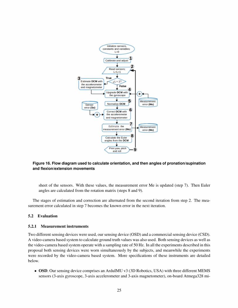
Figure 16. Flow diagram used to calculate orientation, and then angles of pronation/supinationand flexion/extension movements
sheet of the sensors. With these values, the measurement error Me is updated (step 7). Then Eulerangles are calculated from the rotation matrix (steps 8 and 9).
The stages of estimation and correction are alternated from the second iteration from step 2. The mea-surement error calculated in step 7 becomes the known error in the next iteration.
5.2 Evaluation
5.2.1 Measurement instruments
Two different sensing devices were used, our sensing device (OSD) and a commercial sensing device (CSD).A video-camera based system to calculate ground truth values was also used. Both sensing devices as well asthe video-camera based system operate with a sampling rate of 50 Hz. In all the experiments described in thisproposal both sensing devices were worn simultaneously by the subjects, and meanwhile the experimentswere recorded by the video-camera based system. More specifications of these instruments are detailedbelow.
• OSD. Our sensing device comprises an ArduIMU v3 (3D Robotics, USA) with three different MEMSsensors (3-axis gyroscope, 3-axis accelerometer and 3-axis magnetometer), on-board Atmega328 mi-
25
croprocessor running at 16MHz, bluetooth RN-42 communication module for distances to 20m, anda lithium battery of 3.7V at 1000mAh. The approximate weight of our sensing device is 35gm.
• CSD. The commercial sensing device is a LP-Research Motion Sensor Bluetooth version (LPMS-B),a miniature wireless inertial measurement unit (IMU). This device includes three different MEMS sen-sors: 3-axis gyroscope, 3-axis accelerometer and 3-axis magnetometer. Its communication distancescope is 18m, it has a lithium battery of 3.7V at 800mAh, and it weights 34gm.
• Video-camera based system. The video system consists of both, video-camera and tracker software.The video-camera is a Nikon D5200 with 24.1MP CMOS sensor and Full HD (1900⇥1080p) videorecording. The tracker software is a free video analysis and modeling tool built on the Open SourcePhysics (OSP) Java framework, able to track a visual mark and calculate its orientation with respectto a given axis.
5.2.2 Experimental settings
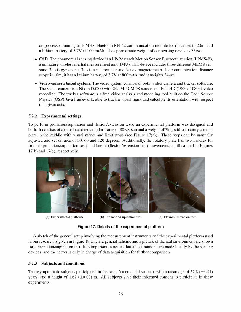
To perform pronation/supination and flexion/extension tests, an experimental platform was designed andbuilt. It consists of a translucent rectangular frame of 80⇥80cm and a weight of 3kg, with a rotatory circularplate in the middle with visual marks and limit stops (see Figure 17(a)). These stops can be manuallyadjusted and set on arcs of 30, 60 and 120 degrees. Additionally, the rotatory plate has two handles forfrontal (pronation/supination test) and lateral (flexion/extension test) movements, as illustrated in Figures17(b) and 17(c), respectively.
(a) Experimental platform (b) Pronation/Supination test (c) Flexion/Extension test
Figure 17. Details of the experimental platform
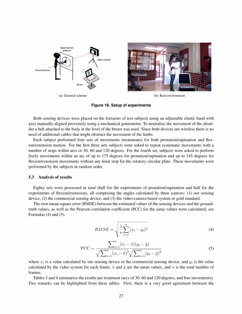
A sketch of the general setup involving the measurement instruments and the experimental platform usedin our research is given in Figure 18 where a general scheme and a picture of the real environment are shownfor a pronation/supination test. It is important to notice that all estimations are made locally by the sensingdevices, and the server is only in charge of data acquisition for further comparison.
5.2.3 Subjects and conditions
Ten asymptomatic subjects participated in the tests, 6 men and 4 women, with a mean age of 27.8 (±4.94)years, and a height of 1.67 (±0.09) m. All subjects gave their informed consent to participate in theseexperiments.
26
(a) General scheme (b) Real environment
Figure 18. Setup of experiments
Both sensing devices were placed on the forearms of test subjects using an adjustable elastic band withaxes manually aligned previously using a mechanical goniometer. To neutralize the movement of the shoul-der a belt attached to the body at the level of the breast was used. Since both devices are wireless there is noneed of additional cables that might obstruct the movement of the limbs.
Each subject performed four sets of movements (treatments) for both pronation/supination and flex-ion/extension motion. For the first three sets subjects were asked to repeat systematic movements with anumber of stops within arcs or 30, 60 and 120 degrees. For the fourth set, subjects were asked to performfreely movements within an arc of up to 175 degrees for pronation/supination and up to 145 degrees forflexion/extension movements without any limit stop for the rotatory circular plate. These movements wereperformed by the subjects in random order.
5.3 Analysis of results
Eighty sets were processed in total (half for the experiments of pronation/supination and half for theexperiments of flexion/extension), all comprising the angles calculated by three sources: (1) our sensingdevice, (2) the commercial sensing device, and (3) the video-camera based system or gold standard.
The root-mean-square error (RMSE) between the estimated values of the sensing devices and the ground-truth values, as well as the Pearson correlation coefficient (PCC) for the same values were calculated, seeFormulas (4) and (5).
RMSE =
vuut 1
n
nX
i=1
(xi
� yi
)2 (4)
PCC =
Xn
i=1(x
i
� x)(yi
� y)qX
n
i=1(x
i
� x)2qX
n
i=1(y
i
� y)2(5)
where xi
is a value calculated by our sensing device or the commercial sensing device, and yi
is the valuecalculated by the video system for each frame, x and y are the mean values, and n is the total number offrames.
Tables 3 and 4 summarize the results per treatment (arcs of 30, 60 and 120 degrees, and free movements).Two remarks can be highlighted from these tables. First, there is a very good agreement between the
27
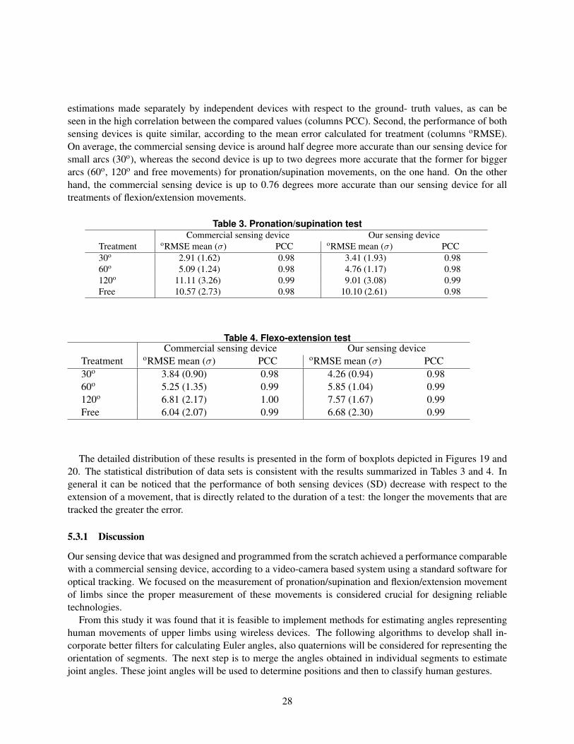
estimations made separately by independent devices with respect to the ground- truth values, as can beseen in the high correlation between the compared values (columns PCC). Second, the performance of bothsensing devices is quite similar, according to the mean error calculated for treatment (columns oRMSE).On average, the commercial sensing device is around half degree more accurate than our sensing device forsmall arcs (30o), whereas the second device is up to two degrees more accurate that the former for biggerarcs (60o, 120o and free movements) for pronation/supination movements, on the one hand. On the otherhand, the commercial sensing device is up to 0.76 degrees more accurate than our sensing device for alltreatments of flexion/extension movements.
Table 3. Pronation/supination testCommercial sensing device Our sensing device
Treatment oRMSE mean (�) PCC oRMSE mean (�) PCC30o 2.91 (1.62) 0.98 3.41 (1.93) 0.9860o 5.09 (1.24) 0.98 4.76 (1.17) 0.98120o 11.11 (3.26) 0.99 9.01 (3.08) 0.99Free 10.57 (2.73) 0.98 10.10 (2.61) 0.98
Table 4. Flexo-extension testCommercial sensing device Our sensing device
Treatment oRMSE mean (�) PCC oRMSE mean (�) PCC30o 3.84 (0.90) 0.98 4.26 (0.94) 0.9860o 5.25 (1.35) 0.99 5.85 (1.04) 0.99120o 6.81 (2.17) 1.00 7.57 (1.67) 0.99Free 6.04 (2.07) 0.99 6.68 (2.30) 0.99
The detailed distribution of these results is presented in the form of boxplots depicted in Figures 19 and20. The statistical distribution of data sets is consistent with the results summarized in Tables 3 and 4. Ingeneral it can be noticed that the performance of both sensing devices (SD) decrease with respect to theextension of a movement, that is directly related to the duration of a test: the longer the movements that aretracked the greater the error.
5.3.1 Discussion
Our sensing device that was designed and programmed from the scratch achieved a performance comparablewith a commercial sensing device, according to a video-camera based system using a standard software foroptical tracking. We focused on the measurement of pronation/supination and flexion/extension movementof limbs since the proper measurement of these movements is considered crucial for designing reliabletechnologies.
From this study it was found that it is feasible to implement methods for estimating angles representinghuman movements of upper limbs using wireless devices. The following algorithms to develop shall in-corporate better filters for calculating Euler angles, also quaternions will be considered for representing theorientation of segments. The next step is to merge the angles obtained in individual segments to estimatejoint angles. These joint angles will be used to determine positions and then to classify human gestures.
28

Figure 19. Boxplot of Pronation/Supination
6 Plan of work
In this chapter a plan of work to accomplish this research is detailed. First, the activities of the firstyear are summarized, and prospective activities to develop in the next years are listed. Then, a schedule ofactivities is shown according to the objectives introduced in Chapter 3.
6.1 Activities of the work plan
In Chapter 4 the main steps of this PhD research were presented. The temporality of these activities isdescribed below, starting with the activities and goals that have been met so far.
6.1.1 Activities that are finished
Initial activities (January - October 2014)
• Attending to INAOE PhD Seminar
• Review and analysis of the state of the art
• Writing and submission of a survey entitled “Wearable Inertial Sensors for Human Motion Analysis:A review” to the International Journal of Medical Informatics
Objective 1, part 1: Estimation of angles of segments (June 2014 - December 2014)
• Characterization and evaluation of inertial sensors
• Experiment 1: Estimation of an angle of a segment respect to an anatomical plane. Forearm seg-ment respect to the frontal plane (flexion/extension) and forearm with respect to the sagittal plane(pronation/supination)
29
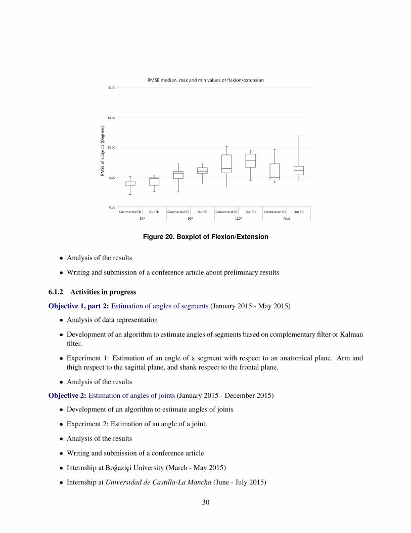
Figure 20. Boxplot of Flexion/Extension
• Analysis of the results
• Writing and submission of a conference article about preliminary results
6.1.2 Activities in progress
Objective 1, part 2: Estimation of angles of segments (January 2015 - May 2015)
• Analysis of data representation
• Development of an algorithm to estimate angles of segments based on complementary filter or Kalmanfilter.
• Experiment 1: Estimation of an angle of a segment with respect to an anatomical plane. Arm andthigh respect to the sagittal plane, and shank respect to the frontal plane.
• Analysis of the results
Objective 2: Estimation of angles of joints (January 2015 - December 2015)
• Development of an algorithm to estimate angles of joints
• Experiment 2: Estimation of an angle of a joint.
• Analysis of the results
• Writing and submission of a conference article
• Internship at Bogazici University (March - May 2015)
• Internship at Universidad de Castilla-La Mancha (June - July 2015)
30

6.1.3 Future work
Objective 3: Estimation of postures (September 2015 - June 2016)
• Development of an algorithm to estimate postures
• Experiment 3: Estimation of a posture
• Analysis of the results
• Writing and submission of journal article
Objective 4: Classification of gestures (June 2016 - May 2017)
• Development of algorithm to classify human gestures
• Experiment 4: Classification of human gestures
• Analysis of the results
• Writing and submission of conference and journal articles
31

6.2 Schedule
32

References
[1] Verne Thompson Inman, Henry James Ralston, and Frank Todd. Human walking. Williams andWilkins, Baltimore, 1981.
[2] Duane Knudson. Fundamentals of biomechanics. Springer Science and Business Media, 2007.
[3] Duane V. Knudson and Craig S. Morrison. Qualitative Analysis of Human Movement. Human Kinetics,2 edition, 2002.
[4] Thomas Beth, Ingo Boesnach, Martin Haimerl, Jorg Moldenhauer, Klaus Bos, and Veit Wank. Char-acteristics in human motion–from acquisition to analysis. In IEEE International Conference on Hu-manoid Robots, pages 56–75, 2003.
[5] Maria Karam and MC Schraefel. A taxonomy of gestures in human computer interactions. 2005.
[6] G Eliezer Quintana, Luis Enrique Sucar, Gildardo Azcarate, and Ron Leder. Qualification of armgestures using hidden markov models. In Automatic Face & Gesture Recognition, 2008. FG’08. 8thIEEE International Conference on, pages 1–6. IEEE, 2008.
[7] L. Peppoloni, A. Filippeschi, E. Ruffaldi, and C.A. Avizzano. A novel 7 degrees of freedom modelfor upper limb kinematic reconstruction based on wearable sensors. In 2013 IEEE 11th InternationalSymposium on Intelligent Systems and Informatics (SISY), pages 105–110, Sept 2013.
[8] Vicon. Vicon motion systems ltd., 2014. Accessed: 2014-10-01. Available from:http://www.vicon.com/.
[9] Optotrak. Northern digital inc., 2014. Accessed: 2014-10-01. Available from:http://www.ndigital.com/msci/products/optotrak-certus/.
[10] Kinect. Microsoft corporation, 2014. Accessed: 2014-10-01. Available from: http://www.kinect.com/.
[11] Xi Chen. Human Motion Analysis with Wearable Inertial Sensors. PhD thesis, University of Tennessee,Knoxville, 2013.
[12] Dennis Charsky. From edutainment to serious games: A change in the use of game characteristics.Games and culture, 2010.
[13] Tiffany Tong, Mark Chignell, Phil Lam, Mary C Tierney, and Jacques Lee. Designing serious gamesfor cognitive assessment of the elderly. In Proceedings of the International Symposium of HumanFactors and Ergonomics in Healthcare, volume 3, pages 28–35. SAGE Publications, 2014.
[14] Christian Schonauer, Thomas Pintaric, Hannes Kaufmann, Stephanie Jansen-Kosterink, and MiriamVollenbroek-Hutten. Chronic pain rehabilitation with a serious game using multimodal input. InVirtual Rehabilitation (ICVR), 2011 International Conference on, pages 1–8. IEEE, 2011.
[15] Marvin J. Greenberg. Euclidean and Non-Euclidean Geometries; Development and History. W. H.Freeman, San Francisco, 1974.
[16] Ayman El-Fatatry. Inertial measurement units imu. Technical report, BAE Systems - Advanced Tech-nology Centre, Chelmsford, United Kingdom, 2004.
33

[17] MedlinePlus. Merriam-webster medical dictionary [internet]. Springfield, MA: Merriam-WebsterIncorporated, 2005. Accesed 2014-12-01. Available from: http://www.nlm.nih.gov/medlineplus/.
[18] Sen M Kuo, Bob H Lee, and Wenshun Tian. Real-Time Digital Signal Processing : Implementationsand Applications. John Wiley and Sons, 2nd edition, 2006.
[19] Keith L. Moore, Arthur F. Dalley, and Anne M. R. Agur. Clinically oriented anatomy. LippincottWilliams and Wilkins, a Wolters Kluwer business, 7th edition, 2014.
[20] Roy B. Davis, Sylvia Ounpuu, Peter A. DeLuca, and Mark J. Romness. Clinical gait analysis and itsrole in treatment decision-making, volume 1 of 1. Medscape General Medicine, 2002.
[21] Sushmita Mitra and Tinku Acharya. Gesture recognition: A survey. IEEE Transactions on Systems,Man, and Cybernetics, Part C: Applications and Reviews, 37(3):311–324, 2007.
[22] MP Lawton and EM Brody. Assessment of older people: Self-maintaining and instrumental activitiesof daily living. Gerontologist, 9(3):179–186, 1969.
[23] MTw. Xsens north america inc., 2014. Accessed: 2014-10-01. Available from:https://www.xsens.com/.
[24] Liberty. Polhemus, 2014. Accessed: 2014-10-01. Available from: http://polhemus.com/motion-tracking/all-trackers/liberty.
[25] PS-2137. Pasco, 2014. Accessed: 2014-10-01. Available from:http://www.pasco.com/prodCatalog/PS/PS-2137 pasport-goniometer-sensor/.
[26] J.E. Bortz. A new mathematical formulation for strapdown inertial navigation. IEEE Transactions onAerospace and Electronic Systems, AES-7(1):61–66, Jan 1971.
[27] J. Cockcroft, J.H. Muller, and C. Scheffer. A novel complimentary filter for tracking hip angles duringcycling using wireless inertial sensors and dynamic acceleration estimation. IEEE Sensors Journal,14(8):2864–2871, Aug 2014.
[28] Wenzheng Hu, E. Charry, M. Umer, A. Ronchi, and S. Taylor. An inertial sensor system for measure-ments of tibia angle with applications to knee valgus/varus detection. In 2014 IEEE Ninth InternationalConference on Intelligent Sensors, Sensor Networks and Information Processing (ISSNIP), pages 1–6,April 2014.
[29] J. Lambrecht and R. Kirsch. Miniature low-power inertial sensors: promising technology for im-plantable motion capture systems. IEEE Transactions on Neural Systems and Rehabilitation Engi-neering, PP(99):1–1, 2014.
[30] S. Slajpah, R Kamnik, and M. Munih. Kinematics based sensory fusion for wearable motion assess-ment in human walking. Computer Methods and Programs in Biomedicine, 116(2):131–144, 10 2014.
[31] Yu-Liang Hsu, Jeen-Shing Wang, Yu-Ching Lin, Shu-Min Chen, Yu-Ju Tsai, Cheng-Ling Chu, andChe-Wei Chang. A wearable inertial-sensing-based body sensor network for shoulder range of motionassessment. In 2013 International Conference on Orange Technologies (ICOT), pages 328–331, March2013.
34

[32] N. Sim, C. Gavriel, W.W. Abbott, and A.A. Faisal. The head mouse - head gaze estimation “in-the-wild” with low-cost inertial sensors for bmi use. In 2013 6th International IEEE/EMBS Conference onNeural Engineering (NER), pages 735–738, Nov 2013.
[33] G. To and M.R. Mahfouz. Modular wireless inertial trackers for biomedical applications. In 2013 IEEE13th Topical Meeting on Silicon Monolithic Integrated Circuits in RF Systems (SiRF), pages 243–245,Jan 2013.
[34] Sheng Zhang, Kang Xiao, Qian Zhang, Hao Zhang, and Yi Liu. Improved extended kalman fusionmethod for upper limb motion estimation with inertial sensors. In 2013 Fourth International Confer-ence on Intelligent Control and Information Processing (ICICIP), pages 587–593, June 2013.
[35] D. Alvarez, J.C. Alvarez, R.C. Gonzalez, and A.M. Lopez. Ambulatory human upper limb joint motionmonitoring. In 2012 IEEE International Instrumentation and Measurement Technology Conference(I2MTC), pages 15–19, May 2012.
[36] Vincent Bonnet, Claudia Mazza , Philippe Fraisse, and Aurelio Cappozzo. A least-squares identi-fication algorithm for estimating squat exercise mechanics using a single inertial measurement unit.Journal of Biomechanics, 45(8):1472 – 1477, 2012.
[37] H.P. Bruckner, C. Spindeldreier, H. Blume, E. Schoonderwaldt, and E. Altenmuller. Evaluation ofinertial sensor fusion algorithms in grasping tasks using real input data: Comparison of computationalcosts and root mean square error. In 2012 Ninth International Conference on Wearable and ImplantableBody Sensor Networks (BSN), pages 189–194, May 2012.
[38] M. El-Gohary and James McNames. Shoulder and elbow joint angle tracking with inertial sensors.IEEE Transactions on Biomedical Engineering, 59(9):2635–2641, Sept 2012.
[39] JF Lin and D Kulic. Human pose recovery using wireless inertial measurement units. Physiologicalmeasurement, 33(12):2099–2115, 12 2012.
[40] K Liu, Y Inoue, and K Shibata. Physical sensor difference-based method and virtual sensor difference-based method for visual and quantitative estimation of lower limb 3D gait posture using accelerometersand magnetometers. Computer methods in biomechanics and biomedical engineering, 15(2):203–210,2 2012.
[41] Xiaoli Meng, Guanhong Tao, Zhiqiang Zhang, Shuyan Sun, Jiankang Wu, and Wai-Choong Wong.Displacement estimation for different gait patterns in micro-sensor motion capture. In 2012 15thInternational Conference on Information Fusion (FUSION), pages 1315–1322, July 2012.
[42] Qilong Yuan and I-Ming Chen. Human velocity and dynamic behavior tracking method for inertialcapture system. Sensors and Actuators A: Physical, 183(0):123 – 131, 2012.
[43] Zhi-Qiang Zhang, Lian-Ying Ji, Zhi-Pei Huang, and Jian-Kang Wu. Adaptive information fusion forhuman upper limb movement estimation. IEEE Transactions on Systems, Man and Cybernetics, PartA: Systems and Humans, 42(5):1100–1108, Sept 2012.
[44] C.M.N. Brigante, N. Abbate, A. Basile, A.C. Faulisi, and S. Sessa. Towards miniaturization of a mems-based wearable motion capture system. IEEE Transactions on Industrial Electronics, 58(8):3234–3241, Aug 2011.
35

[45] E. Charry, M. Umer, and S. Taylor. Design and validation of an ambulatory inertial system for 3-D measurements of low back movements. In 2011 Seventh International Conference on IntelligentSensors, Sensor Networks and Information Processing (ISSNIP), pages 58–63, Dec 2011.
[46] Hao Yang and Juntao Ye. A calibration process for tracking upper limb motion with inertial sensors. In2011 International Conference on Mechatronics and Automation (ICMA), pages 618–623, Aug 2011.
[47] H. Harms, O. Amft, R. Winkler, J. Schumm, M. Kusserow, and G. Troester. Ethos: Miniature ori-entation sensor for wearable human motion analysis. In 2010 IEEE Sensors, pages 1037–1042, Nov2010.
[48] Guo Xiong Lee, Kay Soon Low, and T. Taher. Unrestrained measurement of arm motion basedon a wearable wireless sensor network. IEEE Transactions on Instrumentation and Measurement,59(5):1309–1317, May 2010.
[49] H.Martin Schepers, Daniel Roetenberg, and PeterH. Veltink. Ambulatory human motion tracking byfusion of inertial and magnetic sensing with adaptive actuation. Medical & Biological Engineering &Computing, 48(1):27–37, 2010.
[50] Jung Keun Lee and E.J. Park. A fast quaternion-based orientation optimizer via virtual rotation forhuman motion tracking. IEEE Transactions on Biomedical Engineering, 56(5):1574–1582, May 2009.
[51] Tao Liu, Yoshio Inoue, and Kyoko Shibata. Development of a wearable sensor system for quantitativegait analysis. Measurement, 42(7):978 – 988, 2009.
[52] E Charry, DT Lai, RK Begg, and M Palaniswami. A study on band-pass filtering for calculatingfoot displacements from accelerometer and gyroscope sensors. In Annual International Conference ofthe IEEE Engineering in Medicine and Biology Society. IEEE Engineering in Medicine and BiologySociety, pages 4826–4827, 2009.
[53] J.Y. Goulermas, A.H. Findlow, C.J. Nester, P. Liatsis, Xiao-Jun Zeng, L.P.J. Kenney, P. Tresadern,S.B. Thies, and D. Howard. An instance-based algorithm with auxiliary similarity information forthe estimation of gait kinematics from wearable sensors. IEEE Transactions on Neural Networks,19(9):1574–1582, Sept 2008.
[54] Huiyu Zhou, Thomas Stone, Huosheng Hu, and Nigel Harris. Use of multiple wearable inertial sensorsin upper limb motion tracking. Medical Engineering & Physics, 30(1):123 – 133, 2008.
[55] D. Roetenberg, P.J. Slycke, and P.H. Veltink. Ambulatory position and orientation tracking fusingmagnetic and inertial sensing. IEEE Transactions on Biomedical Engineering, 54(5):883–890, May2007.
[56] A. Plamondon, A. Delisle, C. Larue, D. Brouillette, D. McFadden, P. Desjardins, and C. Lariviere.Evaluation of a hybrid system for three-dimensional measurement of trunk posture in motion. AppliedErgonomics, 38(6):69 –712, 2007.
[57] Gerald M Lerner. Three-axis attitude determination. Spacecraft Attitude Determination and Control,73:420–428, 1978.
36
[58] Malcolm David Shuster and SD Oh. Three-axis attitude determination from vector observations. Jour-nal of Guidance, Control, and Dynamics, 4(1):70–77, 1981.
[59] F Landis Markley. Attitude determination using vector observations: A fast optimal matrix algorithm.Journal of the Astronautical Sciences, 41(2):261–280, 1993.
[60] F Landis Markley. Fast quaternion attitude estimation from two vector measurements. Journal ofGuidance, Control, and Dynamics, 25(2):411–414, 2002.
[61] A.D. Young. Comparison of orientation filter algorithms for realtime wireless inertial posture tracking.In Wearable and Implantable Body Sensor Networks, 2009. BSN 2009. Sixth International Workshopon, pages 59–64, June 2009.
[62] Dan Simon. Kalman filtering. Embedded Systems Programming, 14(6):72–79, 2001.
[63] Hans-Peter Bruckner, Benjamin Kruger, and Holger Blume. Reliable orientation estimation for mobilemotion capturing in medical rehabilitation sessions based on inertial measurement units. Microelec-tronics Journal, 45(12):1603 – 1611, 2014.
[64] Huiyu Zhou and Huosheng Hu. Reducing drifts in the inertial measurements of wrist and elbowpositions. Instrumentation and Measurement, IEEE Transactions on, 59(3):575–585, 2010.
[65] Mary Beth Early. Physical dysfunction practice skills for the occupational therapy assistant. ElsevierHealth Sciences, 3rd edition, 2013.
[66] Hui He, Kazuo Kiguchi, and Etsuo Horikawa. A study on lower-limb muscle activities during dailylower-limb motions. International Journal of Bioelectromagnetism, 9(2):79–84, 2007.
[67] Adalbert I. Kapandji. The Physiology of the Joints, Volume 1: Upper Limb. Churchill Livingstone, 6thedition, 2007.
[68] Francisco Marquez-Aquino. Estimacion del angulo entre dos segmentos de una extremidad unidos poruna articulacion, usando unidades de medicion inercial y magnetometros para el diseno del e-textiles.BSc thesis, Universidad Popular Autonoma de Puebla, 11 2014.
37