establishing the relative merits of interior and spoke
TRANSCRIPT

Marquette Universitye-Publications@MarquetteElectrical and Computer Engineering FacultyResearch and Publications
Electrical and Computer Engineering, Departmentof
7-1-2015
Establishing the Relative Merits of Interior andSpoke-Type Permanent-Magnet Machines WithFerrite or NdFeB Through Systematic DesignOptimizationPeng ZhangMarquette University
Gennadi Y. SizovMarquette University
Dan M. IonelUniversity of Wisconsin - Milwaukee
Nabeel DemerdashMarquette University, [email protected]
Accepted version. IEEE Transactions on Industry Applications, Vol. 51, No. 4 ( July-August 2015):2940-2948. DOI. © 2015 Institute of Electrical and Electronics Engineers (IEEE). Used withpermission.

NOT THE PUBLISHED VERSION; this is the author’s final, peer-reviewed manuscript. The published version may be accessed by following the link in the citation at the bottom of the page.
IEEE Transactoins on Industry Applications, Vol. 51, No. 4 (July/August 2015): pg. 2940-2948. DOI. This article is © Institute of Electrical and Electronics Engineers (IEEE) and permission has been granted for this version to appear in e-Publications@Marquette. Institute of Electrical and Electronics Engineers (IEEE) does not grant permission for this article to be further copied/distributed or hosted elsewhere without the express permission from Institute of Electrical and Electronics Engineers (IEEE).
1
Establishing the Relative Merits of Interior and Spoke-Type Permanent-Magnet
Machines With Ferrite or NdFeB Through Systematic Design Optimization
Peng Zhang Department of Electrical & Computer Engineering, Marquette University, Milwaukee, WI
Gennadi Y. Sizov Department of Electrical & Computer Engineering, Marquette University, Milwaukee, WI
Dan M. Ionel Department of Electrical & Computer Engineering, Marquette University, Milwaukee, WI
Nabeel A. O. Demerdash Department of Electrical & Computer Engineering, Marquette University, Milwaukee, WI
Abstract: In this paper, a multiobjective design optimization method combining design-of-experiments techniques and differential-evolution algorithms is presented. The method was implemented and utilized in order to provide practical engineering insights for the optimal design of interior and spoke-type permanent-magnet machines. Two combinations with 12 slots and 8 poles and 12 slots and 10 poles, respectively, have been studied in conjunction with rare-earth neodymium-iron-boron (NdFeB) and ferrites. As part of the optimization process, a computationally efficient finite-element electromagnetic analysis was employed for estimating the performance of thousands of candidate designs. Three optimization objectives were concurrently considered for minimum total material cost, power losses, and torque ripple, respectively. Independent variables were considered for both the stator and rotor geometries. A discussion based on a systematic comparison is included, showing, among other things and despite common misconception, that comparable cost versus loss Paretos can be achieved with any of the rotor topologies studied.

NOT THE PUBLISHED VERSION; this is the author’s final, peer-reviewed manuscript. The published version may be accessed by following the link in the citation at the bottom of the page.
IEEE Transactoins on Industry Applications, Vol. 51, No. 4 (July/August 2015): pg. 2940-2948. DOI. This article is © Institute of Electrical and Electronics Engineers (IEEE) and permission has been granted for this version to appear in e-Publications@Marquette. Institute of Electrical and Electronics Engineers (IEEE) does not grant permission for this article to be further copied/distributed or hosted elsewhere without the express permission from Institute of Electrical and Electronics Engineers (IEEE).
2
SECTION I.
Introduction
SPOKE-TYPE permanent-magnet (PM) rotors have an inherent flux concentration capability due of the presence of sets of two adjacent radially arranged PMs around a nonmagnetic shaft/hub (see Fig. 1). This can lead to higher flux densities in the air gap as compared to the flux density of each of the PMs.1 This design feature allows, in principle, the replacement of rare-earth magnet materials, e.g., neodymium-iron-boron (NdFeB), by less expensive and widely available ferrites while maintaining competitive performance for the electric machines.
Fig. 1. Cross section of a 12-slot 8-pole spoke ferrite machine.
Different varieties of spoke-type PM machines were studied, for example, in.2,3 A fractional-slot 9-slot 6-pole spoke-type PM machine was designed as a brushless-dc motor and compared with a prototype interior PM (IPM) machine in.2 A 12-slot 10-pole (12S10P) spoke-type ferrite magnet machine with a novel rotor configuration was proposed, prototyped, and tested for a low-speed electric vehicle traction.3 In this particular paper, a spoke ferrite design in a 12-slot 8-pole (12S8P) configuration was studied and compared to 12S10P spoke ferrite/NdFeB magnet machines.
Design of experiments (DOE) techniques and differential evolution (DE) algorithms represent the latest trends for the optimal design methods for electric machines, e.g.4–
5,6,7,8,9,10,11 Previous studies have reported that DOE methods are more effective when the numbers of design variables and candidate designs are relatively small5,6 and that DE
NOT THE PUBLISHED VERSION; this is the author’s final, peer-reviewed manuscript. The published version may be accessed by following the link in the citation at the bottom of the page.
IEEE Transactoins on Industry Applications, Vol. 51, No. 4 (July/August 2015): pg. 2940-2948. DOI. This article is © Institute of Electrical and Electronics Engineers (IEEE) and permission has been granted for this version to appear in e-Publications@Marquette. Institute of Electrical and Electronics Engineers (IEEE) does not grant permission for this article to be further copied/distributed or hosted elsewhere without the express permission from Institute of Electrical and Electronics Engineers (IEEE).
3
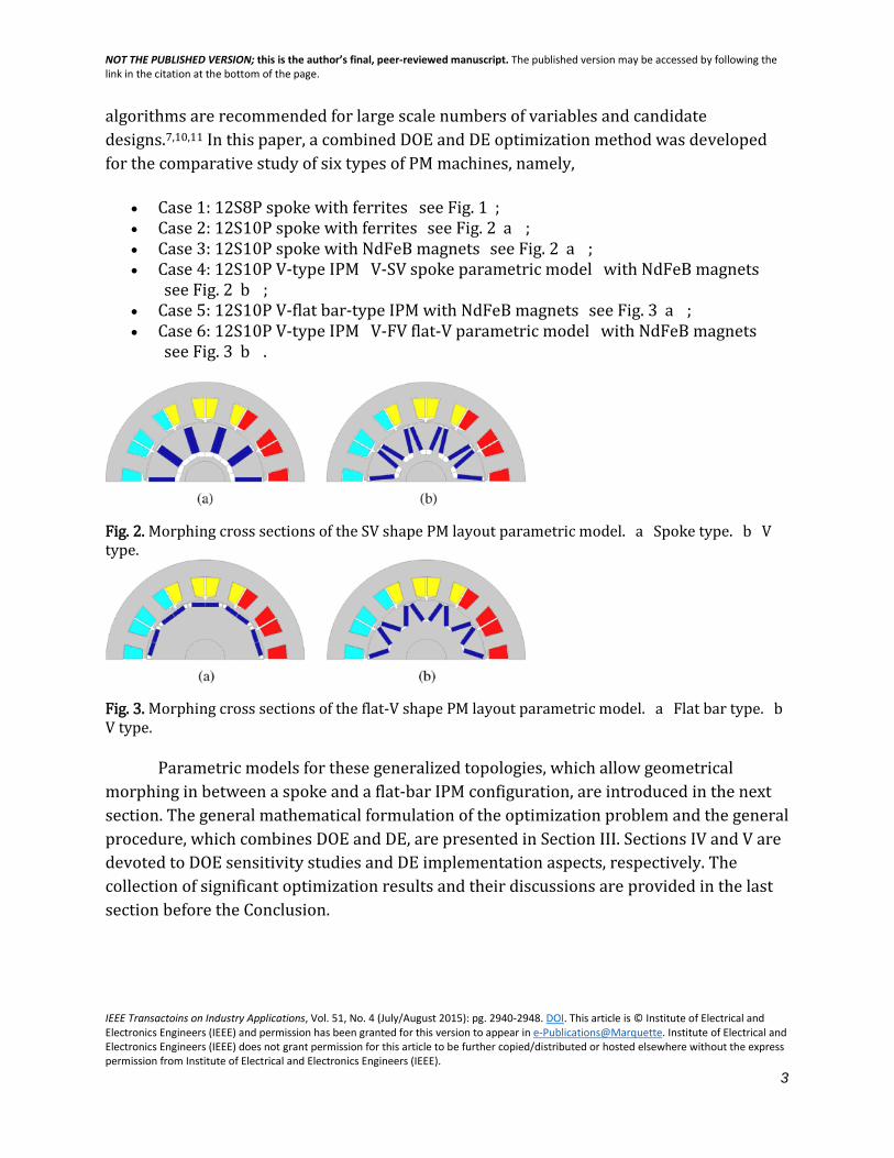
algorithms are recommended for large scale numbers of variables and candidate designs.7,10,11 In this paper, a combined DOE and DE optimization method was developed for the comparative study of six types of PM machines, namely,
• Case 1: 12S8P spoke with ferrites (see Fig. 1); • Case 2: 12S10P spoke with ferrites [see Fig. 2(a)]; • Case 3: 12S10P spoke with NdFeB magnets [see Fig. 2(a)]; • Case 4: 12S10P V-type IPM (V-SV spoke parametric model) with NdFeB magnets
[see Fig. 2(b)]; • Case 5: 12S10P V-flat bar-type IPM with NdFeB magnets [see Fig. 3(a)]; • Case 6: 12S10P V-type IPM (V-FV flat-V parametric model) with NdFeB magnets
[see Fig. 3(b)].
Fig. 2. Morphing cross sections of the SV shape PM layout parametric model. (a) Spoke type. (b) V type.
Fig. 3. Morphing cross sections of the flat-V shape PM layout parametric model. (a) Flat bar type. (b) V type.
Parametric models for these generalized topologies, which allow geometrical morphing in between a spoke and a flat-bar IPM configuration, are introduced in the next section. The general mathematical formulation of the optimization problem and the general procedure, which combines DOE and DE, are presented in Section III. Sections IV and V are devoted to DOE sensitivity studies and DE implementation aspects, respectively. The collection of significant optimization results and their discussions are provided in the last section before the Conclusion.

NOT THE PUBLISHED VERSION; this is the author’s final, peer-reviewed manuscript. The published version may be accessed by following the link in the citation at the bottom of the page.
IEEE Transactoins on Industry Applications, Vol. 51, No. 4 (July/August 2015): pg. 2940-2948. DOI. This article is © Institute of Electrical and Electronics Engineers (IEEE) and permission has been granted for this version to appear in e-Publications@Marquette. Institute of Electrical and Electronics Engineers (IEEE) does not grant permission for this article to be further copied/distributed or hosted elsewhere without the express permission from Institute of Electrical and Electronics Engineers (IEEE).
4
SECTION II.
Parametric PM Machine Models
In order to avoid geometric conflicts during the whole design optimization procedure, robust parametric FEA models needed to be prepared at the first stage. In this paper, all the PM machines have the same output of 10 hp at 1800 r/min with a fixed stator outer diameter (233 mm), as well as a fixed current density of 4 A/mm2 in the stator windings.
Fig. 4. Parametric model for the 12S8P spoke-type PM machine.
A. Spoke-Type PM Machine
The machine geometry and the definition of design variables of the parametric model for a 12S8P spoke ferrite magnet machine are shown in Fig. 4. Eight design variables were selected to be used in the design optimization work. In order to guarantee the robustness of this parametric model, five design variables were defined and expressed as ratios 𝑘𝑘𝑠𝑠𝑠𝑠 , 𝑘𝑘𝑤𝑤𝑤𝑤 , 𝑘𝑘𝑟𝑟𝑟𝑟 , 𝑘𝑘𝑎𝑎𝑎𝑎𝑎𝑎, and 𝑘𝑘𝑤𝑤𝑤𝑤𝑟𝑟 , respectively. These eight design variables are described as follows.

NOT THE PUBLISHED VERSION; this is the author’s final, peer-reviewed manuscript. The published version may be accessed by following the link in the citation at the bottom of the page.
IEEE Transactoins on Industry Applications, Vol. 51, No. 4 (July/August 2015): pg. 2940-2948. DOI. This article is © Institute of Electrical and Electronics Engineers (IEEE) and permission has been granted for this version to appear in e-Publications@Marquette. Institute of Electrical and Electronics Engineers (IEEE) does not grant permission for this article to be further copied/distributed or hosted elsewhere without the express permission from Institute of Electrical and Electronics Engineers (IEEE).
5
1. 𝑘𝑘𝑠𝑠𝑠𝑠 : the stator split ratio between the stator inner radius 𝑅𝑅𝑠𝑠𝑠𝑠 and stator outer radius 𝑅𝑅𝑠𝑠𝑠𝑠 , 𝑘𝑘𝑠𝑠𝑠𝑠 = 𝑅𝑅𝑠𝑠𝑠𝑠/𝑅𝑅𝑠𝑠𝑠𝑠 .
2. ℎ𝑔𝑔: air-gap height. 3. 𝑘𝑘𝑤𝑤𝑤𝑤: the stator tooth width ratio, 𝑘𝑘𝑤𝑤𝑤𝑤 = 𝛼𝛼𝑤𝑤𝑤𝑤/𝛼𝛼𝑠𝑠, where 𝛼𝛼𝑠𝑠is the slot pitch, 𝛼𝛼𝑠𝑠 =
360∘/𝑁𝑁𝑠𝑠, where 𝑁𝑁𝑠𝑠 is the number of stator slots. Here, 𝛼𝛼𝑤𝑤𝑤𝑤 is the tooth angle, which is shown in Fig. 4.
4. 𝑑𝑑𝑦𝑦: the depth of the stator back iron (yoke). 5. 𝑑𝑑𝑤𝑤𝑟𝑟: the depth of bridges on top of the magnets. 6. 𝑘𝑘𝑟𝑟𝑟𝑟: an auxiliary ratio of the magnet width 𝑤𝑤pm. It is defined as 𝑘𝑘𝑟𝑟𝑟𝑟 = (𝑅𝑅𝑟𝑟𝑠𝑠 −
𝑅𝑅pm)/(𝑅𝑅𝑟𝑟𝑠𝑠 − 𝑅𝑅𝑠𝑠ℎ), where 𝑅𝑅𝑟𝑟𝑠𝑠 , 𝑅𝑅pm, and 𝑅𝑅𝑠𝑠ℎare the rotor outer radius, magnet bottom radius, and shaft radius, respectively; see Fig. 4.
7. 𝑘𝑘𝑎𝑎𝑎𝑎𝑎𝑎: the magnet angle ratio, 𝑘𝑘𝑎𝑎𝑎𝑎𝑎𝑎 = 𝛼𝛼pm/𝛼𝛼pm_𝑎𝑎𝑎𝑎𝑚𝑚 , where 𝛼𝛼pm_𝑎𝑎𝑎𝑎𝑚𝑚 is the maximum angle for the PM limited by the minimum bottom distance between two adjacent magnets, 𝛼𝛼pm_𝑎𝑎𝑎𝑎𝑚𝑚 = 𝛼𝛼𝑎𝑎 − 2arcsin (1/2/𝑅𝑅pm) , where 𝛼𝛼𝑎𝑎 is the pole
pitch, 𝛼𝛼𝑎𝑎 = 360∘/𝑃𝑃. Here, P is the number of poles (see Fig. 4). 8. 𝑘𝑘𝑤𝑤𝑤𝑤𝑟𝑟: the magnet bridge width ratio, 𝑘𝑘𝑤𝑤𝑤𝑤𝑟𝑟 = 𝑤𝑤𝑤𝑤𝑟𝑟/ℎpm, where ℎpm =
2𝑅𝑅pmsin (𝛼𝛼pm/2) (see Fig. 4).
In Table I, the eight design variables' ranges are defined based on mechanical limitations and engineering experience.
TABLE I Design and Uncoded Variables for the Parametric Model From Fig. 4 as Used for the DOE Method

NOT THE PUBLISHED VERSION; this is the author’s final, peer-reviewed manuscript. The published version may be accessed by following the link in the citation at the bottom of the page.
IEEE Transactoins on Industry Applications, Vol. 51, No. 4 (July/August 2015): pg. 2940-2948. DOI. This article is © Institute of Electrical and Electronics Engineers (IEEE) and permission has been granted for this version to appear in e-Publications@Marquette. Institute of Electrical and Electronics Engineers (IEEE) does not grant permission for this article to be further copied/distributed or hosted elsewhere without the express permission from Institute of Electrical and Electronics Engineers (IEEE).
6
Fig. 5. Geometric variables for the SV-PM morphing model.
B. SV PM Parametric Model
For the spoke-V (SV) PM parametric model shown in Fig. 5, in order to ensure the robustness of the parametric model, the geometric variable, PM width 𝑤𝑤pm, was expressed through the ratio 𝑘𝑘𝑤𝑤𝑎𝑎𝑎𝑎 = 𝑤𝑤pm/𝑤𝑤pm_𝑎𝑎𝑎𝑎𝑚𝑚 , in which the maximum PM width 𝑤𝑤pm_𝑎𝑎𝑎𝑎𝑚𝑚 can be calculated based on the values of 𝑤𝑤𝑞𝑞 and β as defined in this figure. It should be noted that, for such constructions, the material for the bottom flux barrier has to be nonmagnetic in order to prevent substantial magnet leakage.
In the study presented in the following, this SV-PM parametric model was utilized for both the design optimization of V-type, referred to as V-SV, and spoke-type PM machines. For 12S10P spoke PM machines, the variables 𝑤𝑤𝑞𝑞 , β , and 𝑑𝑑𝑓𝑓𝑤𝑤 , identified in Fig. 5, were equal to 0 mm, 0°, and 0.5 mm, respectively. Thus, there were six design variables for this case study, corresponding to the uncoded vector [𝑘𝑘𝑠𝑠𝑠𝑠 ,ℎ𝑔𝑔,𝑤𝑤𝑇𝑇 ,𝑑𝑑𝑌𝑌,𝛼𝛼𝑓𝑓𝑤𝑤 , 𝑘𝑘𝑤𝑤𝑎𝑎𝑎𝑎] and having the ranges specified in Table II. For the V-SV PM machine shown in Fig. 2(b), all the nine geometric independent variables specified in Table II were selected as design variables for the design optimization algorithms.

NOT THE PUBLISHED VERSION; this is the author’s final, peer-reviewed manuscript. The published version may be accessed by following the link in the citation at the bottom of the page.
IEEE Transactoins on Industry Applications, Vol. 51, No. 4 (July/August 2015): pg. 2940-2948. DOI. This article is © Institute of Electrical and Electronics Engineers (IEEE) and permission has been granted for this version to appear in e-Publications@Marquette. Institute of Electrical and Electronics Engineers (IEEE) does not grant permission for this article to be further copied/distributed or hosted elsewhere without the express permission from Institute of Electrical and Electronics Engineers (IEEE).
7
TABLE II Design Variables for the Spoke and V-SV IPM Machines From Fig. 2. For the Spoke Type, the Variables 𝑤𝑤𝑞𝑞 and β Are Equal to Zero, and 𝑑𝑑𝑓𝑓𝑤𝑤 Was Kept at Its Minimum Value
Fig. 6. Geometric variables for the FV-PM morphing model.
C. Flat-V PM Parametric Model
For the flat-V PM parametric model illustrated in Fig. 6 and a PM tilt angle β of 72° , the rotor geometry corresponds to a flat bar-type PM arrangement as shown in Fig. 3(a), for which seven design variables were selected for this study, namely, 𝑋𝑋 =[𝑘𝑘𝑠𝑠𝑠𝑠 ,ℎ𝑔𝑔,𝑤𝑤𝑇𝑇 ,𝑑𝑑𝑌𝑌,𝛼𝛼𝑓𝑓𝑤𝑤 ,𝑑𝑑𝑓𝑓𝑤𝑤,𝑤𝑤𝑞𝑞]. For 𝛽𝛽 < 72∘, the geometry morphs to a generic V-type PM layout as shown in Fig. 3(b), which is referred to as V-FV PM. In this case, eight design variables were selected, namely, 𝑋𝑋 = [𝑘𝑘𝑠𝑠𝑠𝑠 ,ℎ𝑔𝑔,𝑤𝑤𝑇𝑇 ,𝑑𝑑𝑌𝑌,𝛼𝛼𝑓𝑓𝑤𝑤 ,𝑑𝑑𝑓𝑓𝑤𝑤,𝑤𝑤𝑞𝑞,𝛽𝛽]. The corresponding ranges for all the variables are given in Table III.

NOT THE PUBLISHED VERSION; this is the author’s final, peer-reviewed manuscript. The published version may be accessed by following the link in the citation at the bottom of the page.
IEEE Transactoins on Industry Applications, Vol. 51, No. 4 (July/August 2015): pg. 2940-2948. DOI. This article is © Institute of Electrical and Electronics Engineers (IEEE) and permission has been granted for this version to appear in e-Publications@Marquette. Institute of Electrical and Electronics Engineers (IEEE) does not grant permission for this article to be further copied/distributed or hosted elsewhere without the express permission from Institute of Electrical and Electronics Engineers (IEEE).
8
TABLE III Design Variables for the Flat-Bar and the V-FV IPM-Type Machines From Fig. 3
Fig. 7. Combined design optimization procedure. The performance estimation is based on CE-FEA.
SECTION III.
Optimization Formulation and General Procedure
In the flowchart in Fig. 7, the new combined design optimization method is described. In this flowchart, the DOE method is used to perform the sensitivity study of design variables on three design objectives which include the total losses, material cost, and torque ripple. From this study, the design variables with significant effects on these

NOT THE PUBLISHED VERSION; this is the author’s final, peer-reviewed manuscript. The published version may be accessed by following the link in the citation at the bottom of the page.
IEEE Transactoins on Industry Applications, Vol. 51, No. 4 (July/August 2015): pg. 2940-2948. DOI. This article is © Institute of Electrical and Electronics Engineers (IEEE) and permission has been granted for this version to appear in e-Publications@Marquette. Institute of Electrical and Electronics Engineers (IEEE) does not grant permission for this article to be further copied/distributed or hosted elsewhere without the express permission from Institute of Electrical and Electronics Engineers (IEEE).
9
design objectives were selected, and the ranges of these variables were defined, which contributed to the “well-conditioned” convergence of the DE algorithm. In this design optimization method, the computationally efficient finite-element analysis (CE-FEA) approach12–13,14 was utilized to calculate the performance parameters and characteristics of all obtained design candidate machines. This analysis method utilizes only a reduced set of magnetostatic field solutions to satisfactorily compute the performance of PM machines regulated by sine-wave current supplies.12–13,14
TABLE IV Regression Coefficients for Expression (4) for the 12S8P Ferrite Magnet Machines
The design of a PM machine is subject to conflicting requirements and constraints. A formal mathematical approach for this problem is provided by a multiobjective optimization process. In the following study, three design objectives have been considered.
1. Minimize the losses, including the copper loss, stator core loss, PM loss, and mechanical loss, i.e.,
𝑦𝑦1 = 𝑚𝑚𝑚𝑚𝑚𝑚(𝑃𝑃Cu + 𝑃𝑃Fe + 𝑃𝑃PM + 𝑃𝑃me). (1)
2. Minimize the material cost, with a cost function weighted as follows:
𝑦𝑦2 = 𝑚𝑚𝑚𝑚𝑚𝑚(5𝑚𝑚PM + 8𝑚𝑚Cu + 1𝑚𝑚Fe)forferriteor𝑦𝑦2 = 𝑚𝑚𝑚𝑚𝑚𝑚(65𝑚𝑚PM + 8𝑚𝑚Cu + 1𝑚𝑚Fe)forNdFeB
(2)

NOT THE PUBLISHED VERSION; this is the author’s final, peer-reviewed manuscript. The published version may be accessed by following the link in the citation at the bottom of the page.
IEEE Transactoins on Industry Applications, Vol. 51, No. 4 (July/August 2015): pg. 2940-2948. DOI. This article is © Institute of Electrical and Electronics Engineers (IEEE) and permission has been granted for this version to appear in e-Publications@Marquette. Institute of Electrical and Electronics Engineers (IEEE) does not grant permission for this article to be further copied/distributed or hosted elsewhere without the express permission from Institute of Electrical and Electronics Engineers (IEEE).
10
where 𝑚𝑚PM, 𝑚𝑚Cu, and 𝑚𝑚Fe are masses in kilograms of the ferrite/NdFeB magnet, copper, and steel laminations, respectively.
3. Minimize the torque ripple, with a minimum ripple definition as follows:
𝑦𝑦3 = 𝑚𝑚𝑚𝑚𝑚𝑚 �𝑚𝑚𝑚𝑚𝑚𝑚(𝑇𝑇𝑒𝑒) −𝑚𝑚𝑚𝑚𝑚𝑚(𝑇𝑇𝑒𝑒)
average(𝑇𝑇𝑒𝑒)� .
(3)
Meanwhile, two design constraints are defined by the following expressions:
1. total harmonic distortion in the induced voltage waveform ≤ 10% for the 12S8P combination or ≤ 3% for the 12S10P combination;
2. minimum flux density in the PM ≥ 0.3𝐵𝐵𝑟𝑟 , where the retentivity 𝐵𝐵𝑟𝑟 = 0.43𝑇𝑇 for ferrite magnet or 𝐵𝐵𝑟𝑟 = 1.05𝑇𝑇 for NdFeB magnet.
In the design optimization procedure, the operation temperature for all the candidate designs is assumed to be 100°C . Meanwhile, all the candidate designs have the same slot fill factor and current density, which lead to different ampere-turns for different candidate designs because of their different net slot areas. For each candidate design, the stack length is scaled to obtain a shaft torque of 42 N ⋅ m]], which is corresponding to a 10.6-hp output power rating. The performance of each candidate design is estimated at the maximum-electromagnetic-torque-per-ampere load condition using the method presented in.15 In the copper loss calculation, only the dc ohmic losses generated in the active windings and end windings were included. Ferrite magnets are usually nonconductive magnetic material, which means that the eddy-current losses in the PMs are small enough to be neglected.
SECTION IV.
Design Variables' Sensitivity Study
For better understanding of the sensitivity study procedure in the design optimization algorithms, the 12S8P spoke ferrite magnet machine was selected as the example to be discussed in this section.
NOT THE PUBLISHED VERSION; this is the author’s final, peer-reviewed manuscript. The published version may be accessed by following the link in the citation at the bottom of the page.
IEEE Transactoins on Industry Applications, Vol. 51, No. 4 (July/August 2015): pg. 2940-2948. DOI. This article is © Institute of Electrical and Electronics Engineers (IEEE) and permission has been granted for this version to appear in e-Publications@Marquette. Institute of Electrical and Electronics Engineers (IEEE) does not grant permission for this article to be further copied/distributed or hosted elsewhere without the express permission from Institute of Electrical and Electronics Engineers (IEEE).
11
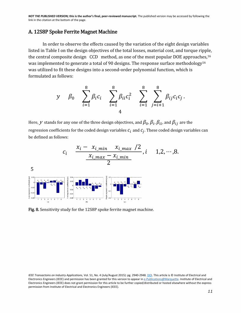
A. 12S8P Spoke Ferrite Magnet Machine
In order to observe the effects caused by the variation of the eight design variables listed in Table I on the design objectives of the total losses, material cost, and torque ripple, the central composite design (CCD) method, as one of the most popular DOE approaches,16 was implemented to generate a total of 90 designs. The response surface methodology16 was utilized to fit these designs into a second-order polynomial function, which is formulated as follows:
𝑦𝑦 = 𝛽𝛽0 + �𝛽𝛽𝑠𝑠𝑐𝑐𝑠𝑠
8
𝑠𝑠=1
+ �𝛽𝛽𝑠𝑠𝑠𝑠𝑐𝑐𝑠𝑠28
𝑠𝑠=1
+ � 8
𝑠𝑠=1
� 𝛽𝛽𝑠𝑠𝑖𝑖𝑐𝑐𝑠𝑠𝑐𝑐𝑖𝑖
8
𝑖𝑖=𝑠𝑠+1
.
(4)
Here, y stands for any one of the three design objectives, and 𝛽𝛽0, 𝛽𝛽𝑠𝑠 , 𝛽𝛽𝑠𝑠𝑠𝑠 , and 𝛽𝛽𝑠𝑠𝑖𝑖 are the
regression coefficients for the coded design variables 𝑐𝑐𝑠𝑠 and 𝑐𝑐𝑖𝑖 . These coded design variables can be defined as follows:
𝑐𝑐𝑠𝑠 =𝑚𝑚𝑠𝑠 − (𝑚𝑚𝑠𝑠_𝑎𝑎𝑠𝑠𝑚𝑚 + 𝑚𝑚𝑠𝑠_𝑎𝑎𝑎𝑎𝑚𝑚)/2
(𝑚𝑚𝑠𝑠_𝑎𝑎𝑎𝑎𝑚𝑚 − 𝑚𝑚𝑠𝑠_𝑎𝑎𝑠𝑠𝑚𝑚)2
, 𝑚𝑚 = 1,2,⋯ ,8.
(5)
Fig. 8. Sensitivity study for the 12S8P spoke ferrite magnet machine.

NOT THE PUBLISHED VERSION; this is the author’s final, peer-reviewed manuscript. The published version may be accessed by following the link in the citation at the bottom of the page.
IEEE Transactoins on Industry Applications, Vol. 51, No. 4 (July/August 2015): pg. 2940-2948. DOI. This article is © Institute of Electrical and Electronics Engineers (IEEE) and permission has been granted for this version to appear in e-Publications@Marquette. Institute of Electrical and Electronics Engineers (IEEE) does not grant permission for this article to be further copied/distributed or hosted elsewhere without the express permission from Institute of Electrical and Electronics Engineers (IEEE).
12
TABLE V Design Variables' Regression Coefficients, 𝛽𝛽𝑠𝑠/𝛽𝛽0, in per Unit, for Cases 2–6. For Cases 2 and 3, No Variables Were Eliminated From DE Optimization. For Cases 4–6, Both 𝑑𝑑𝑓𝑓𝑤𝑤 and 𝑤𝑤𝑞𝑞 Were Eliminated From DE Optimization
For the three design objectives of losses, cost, and torque ripple, the regression coefficients described in (4) are provided in Table IV. The results of the sensitivity studies on the design objectives are provided in Fig. 8(a)–(c), respectively. In these figures, all the first-order regression coefficients are expressed in per unit, which are defined as 𝛽𝛽𝑠𝑠/𝛽𝛽0, where 𝑚𝑚 = 1,2,⋯ ,8. From these sensitivity studies in Table IV and Fig. 8, one can observe that the design variables of the PM bridge depth, 𝑑𝑑𝑤𝑤𝑟𝑟 , and the ratio of the magnet angle, 𝑘𝑘𝑎𝑎𝑎𝑎𝑎𝑎 , have consistent effects on the three design objectives, which means that all of the three design objectives decreased with the decrease of 𝑑𝑑𝑤𝑤𝑟𝑟 and the increase of 𝑘𝑘𝑎𝑎𝑎𝑎𝑎𝑎 . As a consequence, the ratio of the magnet angle, 𝑘𝑘𝑎𝑎𝑎𝑎𝑎𝑎 , should be
set up at its maximum value of 1.0, and the PM bridge depth 𝑑𝑑𝑤𝑤𝑟𝑟should be kept as small as possible (0.5 mm) in order to achieve the optimal design objectives.
Based on these observations, only six design variables are left for the DE design optimization, which are 𝑘𝑘𝑠𝑠𝑠𝑠 , ℎ𝑔𝑔, 𝑘𝑘𝑤𝑤𝑤𝑤 , 𝑑𝑑𝑦𝑦, 𝑘𝑘𝑟𝑟𝑟𝑟 , and 𝑘𝑘𝑤𝑤𝑤𝑤𝑟𝑟 . Because these six design variables have conflicting effects on the three design objectives, the ranges of these variables cannot be reduced. Thus, the ranges of the six design variables given in Table I were kept from being utilized in the DE design optimization procedure. Meanwhile, from Fig. 8(a)–(c), one also can observe that the cost design objective conflicts with the other two design objectives of losses and torque ripple. This means that, in line with expectations, the optimized spoke ferrite magnet machine must have a tradeoff between the cost and losses.

NOT THE PUBLISHED VERSION; this is the author’s final, peer-reviewed manuscript. The published version may be accessed by following the link in the citation at the bottom of the page.
IEEE Transactoins on Industry Applications, Vol. 51, No. 4 (July/August 2015): pg. 2940-2948. DOI. This article is © Institute of Electrical and Electronics Engineers (IEEE) and permission has been granted for this version to appear in e-Publications@Marquette. Institute of Electrical and Electronics Engineers (IEEE) does not grant permission for this article to be further copied/distributed or hosted elsewhere without the express permission from Institute of Electrical and Electronics Engineers (IEEE).
13
B. Other Five Case Studies
The same process was repeated for the other five case study PM machines. All of them have the combination of 12 slots and 10 poles. Only the first-order regression coefficients in per unit are given in Table V. When selecting design variables, the second-order regression coefficients were also taken into account, which reflect the interaction effects between design variables. From the sensitivity study, the number of design variables in the DE algorithm for the other five case studies is 6, 6, 7, 5, and 6, respectively.
Fig. 9. Flowchart for the DE optimization of PM machines. CE-FEA stands for computationally efficient finite-element analysis.

NOT THE PUBLISHED VERSION; this is the author’s final, peer-reviewed manuscript. The published version may be accessed by following the link in the citation at the bottom of the page.
IEEE Transactoins on Industry Applications, Vol. 51, No. 4 (July/August 2015): pg. 2940-2948. DOI. This article is © Institute of Electrical and Electronics Engineers (IEEE) and permission has been granted for this version to appear in e-Publications@Marquette. Institute of Electrical and Electronics Engineers (IEEE) does not grant permission for this article to be further copied/distributed or hosted elsewhere without the express permission from Institute of Electrical and Electronics Engineers (IEEE).
14
SECTION V.
DE Optimization
A DE optimization contains a number of 𝑔𝑔𝑎𝑎𝑎𝑎𝑚𝑚 generations, and each generation has 𝑁𝑁𝑎𝑎 individual designs. Meanwhile, in each design, there are a total number of 𝐷𝐷𝑣𝑣 design variables. In the DE algorithm, the value of 𝑁𝑁𝑎𝑎 should be seven to ten times the value of 𝐷𝐷𝑣𝑣 .17 There are four main processes in the DE algorithm, which are initialization, mutation, crossover, and selection.17 In the initialization procedure, a random process is utilized to produce the first-generation design candidates. After evaluating the first generation, the mutation, crossover, and selection processes were implemented to obtain the next generation, which is explained in the flowchart in Fig. 9. In this figure, there are two control variables, F and 𝐶𝐶𝑟𝑟 . Here, F is the scale factor in the mutation process, 𝐹𝐹 ∈ (0,1+). This scale factor is a positive real value that controls the rate at which the population evolves, and its effective values are seldom greater than “1”.17 Another control variable, 𝐶𝐶𝑟𝑟 , is the crossover probability, 𝐶𝐶𝑟𝑟 ∈ [0,1], which is a user-defined value that controls the fraction of variables' values that are copied from the mutant.17 In the selection step, the trial vectors 𝑈𝑈𝑠𝑠,𝑔𝑔 generated from the crossover process are compared to the target vectors in the current generation, 𝑋𝑋𝑠𝑠,𝑔𝑔, including the design constraints and objectives. Lampinen's selection criterion was adopted to perform this selection procedure to generate the next population, 𝑋𝑋𝑠𝑠,𝑔𝑔+1.17 These processes are repeated until the maximum generation number 𝑔𝑔𝑎𝑎𝑎𝑎𝑚𝑚 is reached. More description for the selection criterion and how the constraints affect the DE algorithm is provided in.15
TABLE VI Simulation Time for the Design Optimization Studies. “D” Stands for the Number of Candidate Designs

NOT THE PUBLISHED VERSION; this is the author’s final, peer-reviewed manuscript. The published version may be accessed by following the link in the citation at the bottom of the page.
IEEE Transactoins on Industry Applications, Vol. 51, No. 4 (July/August 2015): pg. 2940-2948. DOI. This article is © Institute of Electrical and Electronics Engineers (IEEE) and permission has been granted for this version to appear in e-Publications@Marquette. Institute of Electrical and Electronics Engineers (IEEE) does not grant permission for this article to be further copied/distributed or hosted elsewhere without the express permission from Institute of Electrical and Electronics Engineers (IEEE).
15
Fig. 10. Scatterplot of three optimization objectives. The reference values for losses are 400 W.
Fig. 11. Scatterplot comparison between 12S8P spoke ferrite and 12S10P spoke ferrite magnet machines. The reference values for losses are 400 W.
SECTION VI.
Design Optimization Results and Discussions
The DE's three parameters, 𝑔𝑔𝑎𝑎𝑎𝑎𝑚𝑚 , 𝑁𝑁𝑎𝑎, and 𝐷𝐷𝑣𝑣 , for the six case studies and the corresponding simulation times are given in Table VI. These design optimization case

NOT THE PUBLISHED VERSION; this is the author’s final, peer-reviewed manuscript. The published version may be accessed by following the link in the citation at the bottom of the page.
IEEE Transactoins on Industry Applications, Vol. 51, No. 4 (July/August 2015): pg. 2940-2948. DOI. This article is © Institute of Electrical and Electronics Engineers (IEEE) and permission has been granted for this version to appear in e-Publications@Marquette. Institute of Electrical and Electronics Engineers (IEEE) does not grant permission for this article to be further copied/distributed or hosted elsewhere without the express permission from Institute of Electrical and Electronics Engineers (IEEE).
16
studies were performed on an HP Z800 workstation with 12 cores (2 Xeon X5690 processors) and 32-GB RAM memory. The distributed solve function in the ANSYS Maxwell software was utilized for the parallel processing of the candidate designs.18 The typical FEA models employed have 5000–6000 second-order triangular elements.
Fig. 12. Scatterplots and Pareto sets for DE optimization. (a) 12S8P spoke ferrite. (b) 12S10P spoke ferrite. (c) 12S10P spoke NdFeB. (d) 12S10P V-SV NdFeB. (e) 12S10P flat NdFeB. (f) 12S10P V-FV NdFeB.
Fig. 13. Scatterplot with color map for the percentage of the copper losses. (a) 12S8P spoke ferrite. (b) 12S10P spoke ferrite. (c) 12S10P spoke NdFeB. (d) 12S10P V-SV NdFeB. (e) 12S10P flat NdFeB. (f) 12S10P V-FV NdFeB.
For the 12S8P spoke ferrite magnet machines, the 3-D scatterplot for the three objectives (loss, cost, and torque ripple) is shown in Fig. 10, in which each blue circle stands for the performance of each design. The optimal designs are located inside the red solid circle. The Pareto sets' comparison for cost and losses between different combinations of stator slots and rotor poles (12S8P and 12S10P) was performed, which is shown in Fig. 11. Both of these two types of PM machines used the ferrite magnet material. The corresponding torque ripple variation for these two types of PM machines can be observed from the color map in Fig. 12(a) and (b). It is significant that 12S8P spoke ferrite

NOT THE PUBLISHED VERSION; this is the author’s final, peer-reviewed manuscript. The published version may be accessed by following the link in the citation at the bottom of the page.
IEEE Transactoins on Industry Applications, Vol. 51, No. 4 (July/August 2015): pg. 2940-2948. DOI. This article is © Institute of Electrical and Electronics Engineers (IEEE) and permission has been granted for this version to appear in e-Publications@Marquette. Institute of Electrical and Electronics Engineers (IEEE) does not grant permission for this article to be further copied/distributed or hosted elsewhere without the express permission from Institute of Electrical and Electronics Engineers (IEEE).
17
magnet machines can provide designs with lowest losses (highest efficiency). However, the 12S10P spoke ferrite magnet machines can provide designs with the lowest material cost and relatively lower torque ripple. The design optimization results (Pareto sets with the color map for torque ripple) for the other four types of PM machines are shown in Fig. 12(c)–(f), respectively. The NdFeB magnet was adopted in the design optimization of these four types of PM machines (Case 3 to Case 6). All the optimal designs for the six case studies are located along the Pareto fronts (left-bottom corner) in all the figures of Fig. 12(a)–(f).
In Fig. 13, the color maps represent the percentage of the copper loss for each design, which is equal to the copper loss divided by the total losses of each design. For the 12S8P spoke ferrite magnet machines, the copper loss percentage varies from 35% to 40% along the Pareto front (left-bottom corner) in Fig. 13(a). For the 12S10P spoke ferrite magnet machines, the copper loss percentage is around 25% to 30% along the Pareto front in Fig. 13(b). For these two types of ferrite magnet machines (12S8P and 12S10P), the designs with neither high nor low copper loss are not optimal. For the other four types of 12S10P NdFeB magnet machines [see Fig. 13(c)–(f)], the copper loss percentage is around 30% along their Pareto fronts and is lower than 40% in the whole Pareto sets. From these figures, one can observe that, for the 12S10P combination, the magnet material does not change the loss distribution significantly. When changing the combination of stator slots and rotor poles, the loss distribution in the machine changed. The optimal design for the 12S8P combination definitely has higher percentage of copper losses than that of the 12S10P combination.
Fig. 14. Pareto-front comparison between the six case studies.

NOT THE PUBLISHED VERSION; this is the author’s final, peer-reviewed manuscript. The published version may be accessed by following the link in the citation at the bottom of the page.
IEEE Transactoins on Industry Applications, Vol. 51, No. 4 (July/August 2015): pg. 2940-2948. DOI. This article is © Institute of Electrical and Electronics Engineers (IEEE) and permission has been granted for this version to appear in e-Publications@Marquette. Institute of Electrical and Electronics Engineers (IEEE) does not grant permission for this article to be further copied/distributed or hosted elsewhere without the express permission from Institute of Electrical and Electronics Engineers (IEEE).
18
Fig. 15. Effect of design objectives on the optimization results. (a) Three objectives. (b) Two objectives.
The Pareto fronts' comparison for the six case studies is shown in Fig. 14. It is significant that the ferrite magnet material can reduce the material cost of PM machines while maintaining the competitive performance (efficiency) as the NdFeB magnet machines. The combination of 12 slots and 8 poles can reduce the total losses of optimal designs; however, its material cost will be increased when compared to the 12S10P combination. Meanwhile, the 12S10P combination provides relatively lower torque ripple, which contributes to another advantage of this combination.
In line with expectations, the torque ripple for the 12S8P combination is large and can vary in the examples studied between 10% and 60%, providing a clear indication as to why it is very important to consider its minimization as a design objective. The situation is different for the 12S10P combination, in which case the torque ripple is substantially lower, typically below 12%. In this case, only two objectives may be necessary for the optimization, i.e., loss and cost with the torque ripple constrained below 5%. This is shown in Fig. 15 using as an example the 12S10P spoke ferrite magnet motor. The Pareto fronts for the DE with three objectives (loss, cost, and torque ripple) and two objectives (loss and cost), respectively, are comparable, and therefore, the elimination of the third objective is recommended for computational reasons. Accordingly, in all the case studies for the 12S10P combination, the torque ripple was not used as an objective but rather as a constraint in the DE algorithms.
SECTION VII.
Conclusion
As a first step of the design optimization method described in this paper, DOE was employed for a sensitivity study for the three objectives of material cost, power losses, and torque ripple, leading to the selection of the most important parameters as independent

NOT THE PUBLISHED VERSION; this is the author’s final, peer-reviewed manuscript. The published version may be accessed by following the link in the citation at the bottom of the page.
IEEE Transactoins on Industry Applications, Vol. 51, No. 4 (July/August 2015): pg. 2940-2948. DOI. This article is © Institute of Electrical and Electronics Engineers (IEEE) and permission has been granted for this version to appear in e-Publications@Marquette. Institute of Electrical and Electronics Engineers (IEEE) does not grant permission for this article to be further copied/distributed or hosted elsewhere without the express permission from Institute of Electrical and Electronics Engineers (IEEE).
19
variables for the global DE process. This approach resulted in a reduction of the design space, which, in turn, led to fewer candidate designs to be considered per generation/population. Further advantages in terms of reducing the computational effort for the DE optimization were provided through narrower ranges for the variables, as per the DOE findings.
A systematic comparative study of six PM machine topologies, i.e., 12S8P spoke ferrite, 12S10P spoke ferrite, 12S10P spoke NdFeB, 12S10P V-SV NdFeB, 12S10P flat-type NdFeB, and 12S10P V-FV NdFeB, was performed for an example rating of 10 hp and 1800 r/min. The results show that, within the limits considered in the study and despite common misconception, similar Pareto fronts of cost versus loss can be achieved basically with any NdFeB-based design of the spoke or IPM, V-shape or flat-bar, type. This is not to say that particular configurations do not hold advantages in terms of other aspects, such as manufacturability and protection against demagnetization.
The optimization study is also illustrative of the relative merits of the spoke ferrite designs, showing that these can achieve comparable and even higher efficiency at substantially lower cost of up to 40% than their NdFeB counterparts of the same rating. However, another interesting and somewhat unexpected finding for the example IPM and spoke-type study is that, when core losses are significant and are taken into account, a 12-slot 8-pole combination can provide optimal designs with lower losses, albeit at higher material cost and higher torque ripple than the 12-slot 10-pole combination.
ACKNOWLEDGMENT
The authors would like to thank S. Stretz and A. Yeadon of Regal Beloit Corporation and M. Solveson of ANSYS.
References 1D. M. Ionel, R. J. Heideman, and R. P. Bartos, “Spoke permanent magnet rotors for electrical
machines and methods of manufacturing same,” U.S. Patent 7 148 598, Oct. 23, 2003. 2H.-W. Kim, K.-T. Kim, B.-W. Kim, J. Hur, and Y.-S. Jo, “Design of new spoke type brushless dc motor
for neodymium permanent magnet free,” in Proc. IEEE VPPC, 2012, pp. 133–137. 3S.-I. Kim, J. Cho, S. Park, T. Park, and S. Lim, “Characteristics comparison of a conventional and
modified spoke-type ferrite magnet motor for traction drives of low-speed electric vehicles,” in Proc. IEEE ECCE, 2012, pp. 3048–3054.

NOT THE PUBLISHED VERSION; this is the author’s final, peer-reviewed manuscript. The published version may be accessed by following the link in the citation at the bottom of the page.
IEEE Transactoins on Industry Applications, Vol. 51, No. 4 (July/August 2015): pg. 2940-2948. DOI. This article is © Institute of Electrical and Electronics Engineers (IEEE) and permission has been granted for this version to appear in e-Publications@Marquette. Institute of Electrical and Electronics Engineers (IEEE) does not grant permission for this article to be further copied/distributed or hosted elsewhere without the express permission from Institute of Electrical and Electronics Engineers (IEEE).
20
4Y. Duan and D. M. Ionel, “A review of recent developments in electrical machine design optimization methods with a permanent magnet synchronous motor benchmark study,” IEEE Trans. Ind. Appl., vol. 49, no. 3, pp. 1268–1275, May/Jun. 2013.
5Y. Duan and D. Ionel, “Non-linear scaling rules for brushless pm synchronous machines based on optimal design studies for a wide range of power ratings,” IEEE Trans. Ind. Appl., vol. 50, no. 2, pp. 1044–1052, Mar./Apr. 2014.
6S.-I. Kim, J.-P. Hong, Y.-K. Kim, H. Nam, and H.-I. Cho, “Optimal design of slotless-type PMLSM considering multiple responses by response surface methodology,” IEEE Trans. Magn., vol. 42, no. 4, pp. 1219–1222, Apr. 2006.
7G. Y. Sizov, P. Zhang, D. M. Ionel, N. A. O. Demerdash, and M. Rosu, “Automated multi-objective design optimization of PMac machines using computationally efficient FEA and differential evolution,” IEEE Trans. Ind. Appl., vol. 49, no. 5, pp. 2086–2096, Sep./Oct. 2013.
8L. Jolly, M. Jabbar, and L. Qinghua, “Design optimization of permanent magnet motors using response surface methodology and genetic algorithms,” IEEE Trans. Magn., vol. 41, no. 10, pp. 3928–3930, Oct. 2005.
9B. Cassimere and S. Sudhoff, “Population-based design of surfacemounted permanent-magnet synchronous machines,” IEEE Trans. Energy Convers., vol. 24, no. 2, pp. 338–346, Jun. 2009.
10W. Jiang, T. Jahns, T. Lipo, W. Taylor, and Y. Suzuki, “Machine design optimization based on finite element analysis in a high-throughput computing environment,” in Proc. IEEE ECCE, 2012, pp. 869–876.
11G. Pellegrino and F. Cupertino, “FEA-based multi-objective optimization of IPM motor design including rotor losses,” in Proc. IEEE ECCE, Sep. 2010, pp. 3659–3666.
12G. Y. Sizov, D. M. Ionel, and N. A. O. Demerdash, “Modeling and parametric design of permanent-magnet ac machines using computationally efficient-finite element analysis,” IEEE Trans. Ind. Electron., vol. 59, no. 6, pp. 2403–2413, Jun. 2012.
13P. Zhang, G. Sizov, J. He, D. M. Ionel, and N. Demerdash, “Calculation of magnet losses in concentrated-winding permanent magnet synchronous machines using a computationally efficient finite-element method,” IEEE Trans. Ind. Appl., vol. 49, no. 6, pp. 2524–2532, Nov./Dec. 2013.
14G. Y. Sizov et al., “Modeling and analysis of effects of skew on torque ripple and stator tooth forces in permanent magnet ac machines,” in Proc. IEEE ECCE, 2012, pp. 3055–3061.
15P. Zhang et al., “Multi-objective tradeoffs in the design optimization of a brushless permanent magnet machine with fractional-slot concentrated windings,” IEEE Trans. Ind. Appl., vol. 50, no. 5, pp. 3285–3294, Sep./Oct. 2014.
16R. H. Myers and D. C. Montgomery, Response Surface Methodology: Process and Product Optimization Using Designed Experiments. Hoboken, NJ, USA: Wiley, 2002.
17K. V. Price, R. M. Storn, and J. A. Lampinen, Differential Evolution—A Practical Approach to Global Optimization. Berlin, Germany: Springer-Verlag, 2005.
18ANSYS Maxwell. [Online]. Available: http://www.ansys.com/