est3 synergy enabled 3-modcom self study · pdf file3-modcom self study course ... the scope...
TRANSCRIPT

EST3 Synergy Enabled®
3-MODCOMSelf Study Course
P/N 3100340 • Original • 09JULY01

DEVELOPED BY Edwards Systems Technology6411 Parkland DriveSarasota, FL 34243(941) 739–4203
COPYRIGHT NOTICE Copyright © 2001 Edwards Systems Technology, Inc.
This manual and the products it describes are copyrighted byEdwards Systems Technology, Inc. (EST). You may notreproduce, translate, transcribe, or transmit any part of thismanual without express, written permission from EST.
This manual contains proprietary information intended fordistribution to authorized persons or companies for the solepurpose of conducting business with Edwards SystemsTechnology, Inc. If you distribute any information contained inthis manual to unauthorized persons, you have violated alldistributor agreements and we may take legal action.
TRADEMARKS Microsoft is a trademark of Microsoft Corporation.
Microsoft Mouse is a trademark of Microsoft Corporation.
Windows is a trademark of Microsoft Corporation.
CREDITS This course was developed and written by the EST TechnicalInstitute in conjunction with the Documentation Department,Sarasota.
DOCUMENT HISTORY
Date Revision Reason for change
09JULY01 1.0 Initial release
MODCOM Self-Study Course i
Content
Module 1 3-MODCOM Product Description • 1.1Introduction to module 1 • 1.2Key items • 1.4Objectives • 1.53-MODCOM/3-MODCOMP Overview • 1.6Configuring the MODCOM • 1.13MODCOM Dialer Transmission Process • 1.14Programming the MODCOM • 1.18MODCOM Installation Considerations • 1.36Module 1 evaluation • 1.40
Module 2 Configuring the MODCOM • 2.1Introduction to module 2 • 2.2Key items • 2.3Objectives • 2.4Entering the MODCOM into a Project • 2.5Configuring MODCOM General Operating Parameters • 2.9Configuring MODCOM Receiver Properties • 2.16Configuring MODCOM Account Properties • 2.25Module 2 evaluation • 2.31
Module 3 MODCOM Communication Protocols • 3.1Introduction to module 3 • 3.2Key items • 3.3Objectives • 3.4Supported Message Protocols • 3.5Contact ID Coded Messages • 3.7SIA DCS Coded Messages • 3.18SIA P2 (3/1) and SIA P3 (4/2) Coded Messages • 3.26TAP Protocol Coded Messages (Pager Applications) • 3.28Module 3 evaluation • 3.33
Module 4 Programming MODCOM Applications • 4.1Introduction to module 4 • 4.2Key items • 4.3Objectives • 4.4General Fire Alarm MODCOM Dialer Applications • 4.5Module evaluation • 4.16

Content
ii MODCOM Self-Study Course
Important information
Limitation of liabilityThis product has been designed to meet the requirements ofNFPA Standard 72, 1993 Edition; Underwriters Laboratories,Inc., Standard 864, 7th Edition; and Underwriters Laboratoriesof Canada, Inc., Standard ULC S527. Installation in accordancewith this manual, applicable codes, and the instructions of theAuthority Having Jurisdiction is mandatory. EST shall not underany circumstances be liable for any incidental or consequentialdamages arising from loss of property or other damages or lossesowing to the failure of EST products beyond the cost of repair orreplacement of any defective products. EST reserves the right tomake product improvements and change product specificationsat any time.
While every precaution was taken during the preparation of thismanual to ensure the accuracy of its contents, EST assumes noresponsibility for errors or omissions. Features described in thismanual are subject to change without notice.
FCC warningThis equipment can generate and radiate radio frequency energy.If this equipment is not installed in accordance with this manual,it may cause interference to radio communications. Thisequipment has been tested and found to comply within the limitsfor Class A computing devices pursuant to Subpart B of Part 15of the FCC Rules. These rules are designed to providereasonable protection against such interference when thisequipment is operated in a commercial environment. Operationof this equipment is likely to cause interference, in which casethe user at his own expense, will be required to take whatevermeasures may be required to correct the interference.

Content
MODCOM Self-Study Course iii
EST3 Self-Study Course introductionWelcome to Edwards Systems Technology’s EST3 SynergyEnabled® 3-MODCOM Self-Study Course. This course isdesigned to train you, the technician, in componentidentification, function, installation and programming practicesfor the 3-MODCOM and 3-MODCOMP. The materials for thiscourse include:• EST3 Self-Study Course Manual (p/n3100340)• EST3 Installation and Service Manual, P/N 270380, Rev 4.0 or
later.
This self-study course is also designed to facilitate your use ofthe EST3 technical reference manuals and the SDU HELPUtility. While taking this course, keep the manuals close by, asyou will be referred to them on frequent occasions. You willalso need to update your 3-SDU to version 3.0 or greater. Youwill be required to create a practice project during this lesson.
The course consists of four modules covering the 3-MODCOMcomponents and their installation, its configuration, developingmessage protocols, and programming the MODCOM as a dialerfor General Fire Alarm applications. The modules were designedfor use in a logical progression. Accordingly, study them in theorder in which they are presented.
To answer any questions or concerns encountered while studyingthese modules, you can contact a course instructor at the ESTTraining Department.
Upon completion of this entire self-study course take the onlinemodule examination at our WEB Site.

Content
iv MODCOM Self-Study Course
Simply go to www.EST.net, select Training, sign-in, selectonline training, select Self-Study Testing and select3-MODCOM Self-Study Test (P/N 3100329).
During this test the SDU Online Help is available for yourreference while you are taking the test. Simply click on the helpbutton to launch Help at any time.
An average grade of 85 for this online test is required forsuccessful completion. Upon satisfactory completion, you arequalified to purchase the 3-MODCOM and 3-MODCOMPModem Communicator module and to develop applicationsusing these products.
The scope of this self-study is for Fire Alarm system onlyapplications of these products. Using the MODCOM products inmore sophisticated integrated fire, security and access controlapplications is covered in the factory based EST3 SynergyEnabled® Certification Course. Checkout the quarterly trainingschedule on our Web Site for the available of this course.
Content
MODCOM Self-Study Course v
Mail any correspondence to:
Edwards Systems TechnologyTraining Department6411 Parkland DriveSarasota, FL 34243
Our FAX number is: (941) 755-7387
To talk to an instructor, please call (941) 739-4304.
Caution: Use caution when using this course material as areference manual after completing the course. Changes andadditions to EST3 will continue for the life of the product. Thesewill be added to the EST3 technical reference manuals inperiodic revisions. Your course material will NOT receive theserevisions. The Installation Sheets received with hardwarewill contain the most current information.
Course Prerequisites:• You must be EST3 certified and have the 3-SDU, version 3.0
or greater installed on your PC.
• You should have a basic understanding Fire Alarm dialerapplications.

Content
vi MODCOM Self-Study Course

MODCOM Self-Study Course 1.1
Module 1 3-MODCOM Product Description
Summary
This self-study module introduces you to the Integrated EST3System’s 3-MODCOM and 3-MODCOMP ModemCommunicator modules and provides a general description oftheir features, requirements, installation and applications.
ContentIntroduction to module 1 • 1.2Key items • 1.4Objectives • 1.53-MODCOM/3-MODCOMP Overview • 1.6Configuring the MODCOM • 1.13MODCOM Dialer Transmission Process • 1.14Programming the MODCOM • 1.18
The Command List • 1.22The Command Qualifiers • 1.25Numerical Indexing or N-Variables • 1.26Substitution Strings • 1.28Hexadecimal Indexing or H-Variables • 1.32
MODCOM Installation Considerations • 1.36Telephone Line Requirements • 1.36Installing the MODCOM Module • 1.37Connecting the MODCOM to the TELCO Lines • 1.39
Module 1 evaluation • 1.40
3-MODCOM Product Description
1.2 MODCOM Self-Study Course
Introduction to module 1The 3-MODCOM and 3-MODCOMP Modem Communicatorsincorporate modem and dialer functions into the integratedEST3 system architecture. These EST3 modules are Local RailModules (LRMs) that employ the snap-fit technology used forthe other EST3 LRMs. These MODCOM LRMs easily installon the chassis rail slots in the EST3 cabinet enclosures.
The 3-SDU, version 3.0 or greater enables you to develop fullyintegrated Fire, Security and Access Control systemapplications. The integrated EST3 system architecture employsthe MODCOM LRMs as:
� A modem to download and maintain Access Control andKeypad Display data into the integrated EST3 system.
� A dialer to report Fire, Security and Access Controlpremises events to a Central Station monitoring serviceand/or pager.
This self-study module is the 3-MODCOM and 3-MODCOMPproduct description, which describes the features andcapabilities of both MODCOM types. This module alsodescribes MODCOM operation, describes MODCOMinstallation considerations, and introduces you to the basicMODCOM configuration and programming process required toincorporate the MODCOM into an integrated EST3 systemenvironment.
This self-study course is designed for those who are EST3certified for fire alarm systems. Successful completion of thisMODCOM self-study course results in certification, whichenables you to purchase the MODCOM products andincorporate them into your EST3 applications using the 3-SDUversion 3.0 or greater.
The 3-MODCOM and 3-MODCOMP products are also taught aspart of a factory course on EST3 Synergy Enabled® AccessControl and Security products. You can find a description ofthis factory course on our web site (www.EST.net) as EST3Synergy Enabled® Certification Course (P/N 3100330).. If youintend to use these integrated Access Control and Securityproducts you need to attend this factory course to gaincertification.

3-MODCOM Product Description
MODCOM Self-Study Course 1.3
Associated study
Prior to starting this course you should update your SDU toversion 3.0. This will make the SDU’s onboard Help Utilityavailable to you as a training aid. Prior to starting this course goto the Help Utility, select the Search tab, search on MODCOMand review the related MODCOM help files. Remember thatyou can print out the file for review if you desire a paper copy.
Use the following technical reference manuals as associatedstudy material for this module:
• EST3 Installation and Service Manual, P/N 270380, Rev 4.0 orlater)
• EST3 System Operations Manual, (P/N 270382, Rev 4.0 or later)• Modem Communicator 3-MODCOM/3-MODCOMP Installation
Sheet, (P/N 387476)
Copies of these manuals and the 3-SDU’s Help Utility are alsoavailable on the Fire Alarm Support Tools, Online SupportSystem CD (P/N 270395, Rev 5.0 or later).
This Online Support System CD and its onboard Help Utility areuseful tools. The minimum system requirements for your PC orlaptop are:
• IBM compatible Pentium computer• SVGA monitor (800 x 600 pixel at 256 color)• Windows 95 or greater• 2X CD-ROM drive• Current version of Acrobat Reader, which is available on this
CD.
This CD also contains all the product installation sheetsavailable as of its date of publication. It would be impossible forEST to maintain these installation sheets at their currentrevisions on the CD or in the published manuals. The CD andmanuals are updated only when major changes to the system aremade. The actual installation sheets, shipped with the productcomponents, reflect the current revision levels. It would be goodpractice to maintain a current set of these installation sheets onsite and/or at your office.
It may also be helpful to develop a practice project in the 3-SDUduring this self-study course. This will enable you to refine yourskills at developing MODCOM applications and becomefamiliar with the SDU tools.

3-MODCOM Product Description
1.4 MODCOM Self-Study Course
Key itemsKey points to look for:
• 3-MODCOM/3-MODCOMP modem function.• 3-MODCOM/3-MODCOMP dialer function.• Downloading EST3 application data.• Premise event reporting to a monitoring service.• Any Ring, Normal Ring, Long-Long Distinct Ring, Short-
Short-Long Distinct Ring, Short-Long-Short Distinct Ringdetection and answering modes.
• Required RJ-31X and RJ-38X telephone jacks.• One/Two loop start line or public switched telephone line
compatibility.• Bell 103 and V.32 compliant 14.4 K-baud modem.• 1-Line Dialer, 2-Line Dialer, Modem, 1-Line Dialer with
Modem and 2-Line Dialer with Modem MODCOMapplications are supported.
• Contact ID, SIA DCS, SIA P2 and SIA P3 Central StationCommunication Protocols are supported.
• TAP Pager Protocol is supported in 3-MODCOMP.• General, Zoned and Point ID Central Station event reporting
is supported.• Called Party Disconnect service requirement to prevent
jamming from incoming calls.• Preset default NFPA 72 Certified Fire Alarm and Burglary
System compliance operation.
Key terms and components to learn:
• Receivers• Accounts• Command List• Command Qualifiers• Activation Event• Activate Command• Restore Command• Send Command• Command Qualifiers• Substitution Strings• Hexadecimal Indexing
3-MODCOM Product Description
MODCOM Self-Study Course 1.5
Objectives
Upon completion of this module you will be able to:
1. Identify the 3-MODCOM and 3-MODCOMP modules.
2. Determine the various MODCOM, telephone line andCentral Station requirements for your application.
3. Describe the basic transmission/communication process forthe MODCOM dialer.
4. Describe NFPA 72 compliance requirements for MODCOMapplications.
5. Describe the purpose of configured MODCOM receiversand accounts.
6. Describe the basic programming function of a command list,send command, command qualifier, numerical indexing,hexadecimal indexing and substitution strings.
7. Physically install the 3-MODCOM and 3-MODCOMP intoan EST3 cabinet enclosure.
3-MODCOM Product Description
1.6 MODCOM Self-Study Course
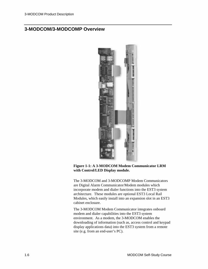
3-MODCOM/3-MODCOMP Overview
Figure 1-1: A 3-MODCOM Modem Communicator LRMwith Control/LED Display module.
The 3-MODCOM and 3-MODCOMP Modem Communicatorsare Digital Alarm Communicator/Modem modules whichincorporate modem and dialer functions into the EST3 systemarchitecture. These modules are optional EST3 Local RailModules, which easily install into an expansion slot in an EST3cabinet enclosure.
The 3-MODCOM Modem Communicator integrates onboardmodem and dialer capabilities into the EST3 systemenvironment. As a modem, the 3-MODCOM enables thedownloading of information (such as, access control and keypaddisplay applications data) into the EST3 system from a remotesite (e.g. from an end-user’s PC).
3-MODCOM Product Description
MODCOM Self-Study Course 1.7
As a dialer, the 3-MODCOM sends alarm, supervisory andtrouble information to a remote site (e.g. Central Station) usingone or two phone lines. This information can be reported in adual or split format.
Note: The 3-MODCOM dialer is used for event reporting to amonitoring station called a Central Monitoring Station (CMS).During this self-study course we will use the term CentralStation, CMS or Central Monitoring Station interchangeably.Where Central Monitoring Station is the formal terminology andCentral Station is conversationally more popular.
The 3-MODCOMP Modem Communicator provides the samemodem/dialer functions as the 3-MODCOM with the addition ofalso sending information to individually predefined pagers.
Both the 3-MODCOM and 3-MODCOMP are standard type,single-slot LRMs, which support mounting any of the four EST3Control/LED display modules as shown in Figure 1-1.
These MODCOMs are shipped with two 7 foot, 8-position flattelephone cables with an 8-position modular plug on both ends(P/N 3601377). Line supervision is configurable for bothMODCOM phone lines, where line supervision may be enabledor disabled for each phone line.
One end of each cable plugs directly into the two jacks at the topof the MODCOM (shown in Figure 1-2 and Figure 1-3). Theother end of each cable plugs directly into a correspondingRJ31X or RJ38X telephone jack, which is obtained locally andwired to a switched telephone network. In Canada use CA31Aor CA38A telephone jacks.
CAUTION: Failure to use an RJ31X or RJ38X jack violatesFCC and NFPA regulations. A telephone connected directly toan incoming phone line can cause TELCO trouble and canpossibly prevent the dialer from connecting to the CentralStation during an emergency.
These jacks must be installed within 5 feet of the cabinet thathouses the MODCOM. Note that each MODCOM phone linehas an LED to annunciate line ringing and data exchange.
Both MODCOM modules are compatible with one/two loopstart line on public switched telephone network, with pulse ortouch-tone (DTMF) dialing. Both MODCOM modules have anonboard Bell 103 and V.32 bis compliant, 14.4K-baud modem.
3-MODCOM Product Description
1.8 MODCOM Self-Study Course
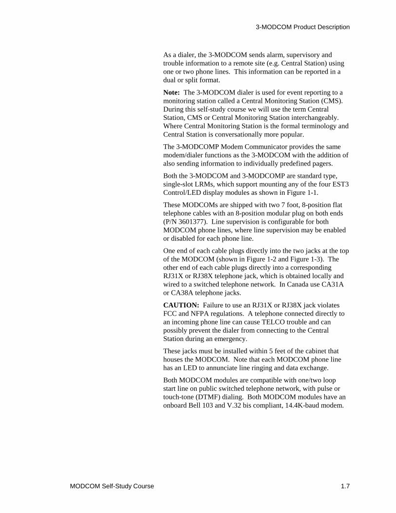
Two 8-position modular phone plugs
Figure 1-2: A 3-MODCOM Modem Communicator LRMfront and back views.
These MODCOM modules can be configured to detect andanswer:
� Any Ring.
� Normal Ring.
� Long-Long Distinct Ring.
� Short-Long-Short Distinct Ring.
� Short-Short Long Distinct Ring.
Only MODCOM phone line 1 (J 20) contains a ring detectioncircuit and can be used to receive incoming calls.
J1 Control/LEDdisplay panelribbon cableconnection
DS1 and DS2LEDs annunciateline ringing anddata exchangeBACK VIEW FRONT VIEW

3-MODCOM Product Description
MODCOM Self-Study Course 1.9
Figure 1-3: Typical MODCOM interconnection using RJ31Xconnectors.
These MODCOM modules are not plug-and-play. They areeasily configurable and programmable to meet a variety ofmodem and dialer applications. You can configure and programeither MODCOM for the following applications:
� 1-Line Dialer.
� 2-Line Dialer.
� Modem.
� Modem with 1-Line Dialer.
� Modem with 2-Line Dialer.
J20 J21
1
2
34 5
6
7
8 1
2
34 5
6
7
8
PremisesPhones
RJ31X 8-pinModular Connector
PhoneLine 1 Line 2
RJ31X 8-pinModular Connector
Phone
(Wiredame as
PhoneLine 1)
s
SurgeProtector
TIP(Green)
Yellow
Black
Supplied 7-foot, 8-positionflat telephone phonecables (P/N 3601377)
J20 and J21 positionsare based on viewing
the MODCOM modulefrom the front
3-MODCOM Product Description
1.10 MODCOM Self-Study Course
Both MODCOM types support the following transmissionprotocols:
Contact ID, which consists of numeric codes with severaloptional parameters, such as:
[EventCode][Partition][DeviceNumber][User]
SIA DCS, which consists of ASCII Text codes with severaloptional parameters, such as:
[Date][Time][UserID][AlarmCode][Device][User][Partition]
SIA P2 (20 pulses/round 3/1), which consists of numeric codesof four digits, containing a 1-digit alarm code:
[AlarmCode]
SIA P3 (4/2 double round), which consists of 2-digit numericevent codes:
[EventCode]
The 3-MODCOMP also supports Telelocator AlphanumericProtocol (TAP) for pager applications. TAP consists of twofields of up to 59 characters separated by a carriage return (CR):
[UserID] CR [ASCCI Text Message]
where the message is generally the event type and devicelocation within the protected facility.
Note: In all cases, the Account Code would be part of thetransmission to the Central Station or Pager Service.
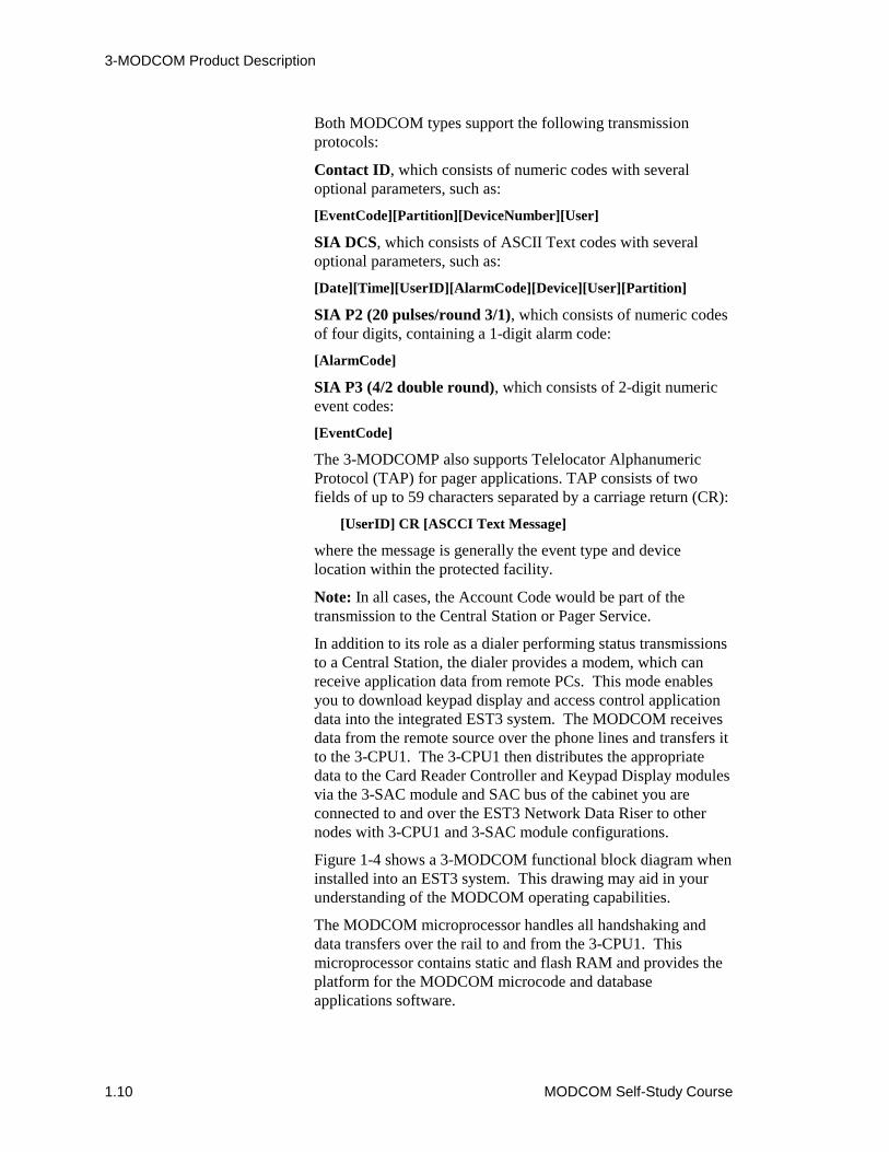
In addition to its role as a dialer performing status transmissionsto a Central Station, the dialer provides a modem, which canreceive application data from remote PCs. This mode enablesyou to download keypad display and access control applicationdata into the integrated EST3 system. The MODCOM receivesdata from the remote source over the phone lines and transfers itto the 3-CPU1. The 3-CPU1 then distributes the appropriatedata to the Card Reader Controller and Keypad Display modulesvia the 3-SAC module and SAC bus of the cabinet you areconnected to and over the EST3 Network Data Riser to othernodes with 3-CPU1 and 3-SAC module configurations.
Figure 1-4 shows a 3-MODCOM functional block diagram wheninstalled into an EST3 system. This drawing may aid in yourunderstanding of the MODCOM operating capabilities.
The MODCOM microprocessor handles all handshaking anddata transfers over the rail to and from the 3-CPU1. Thismicroprocessor contains static and flash RAM and provides theplatform for the MODCOM microcode and databaseapplications software.
3-MODCOM Product Description
MODCOM Self-Study Course 1.11
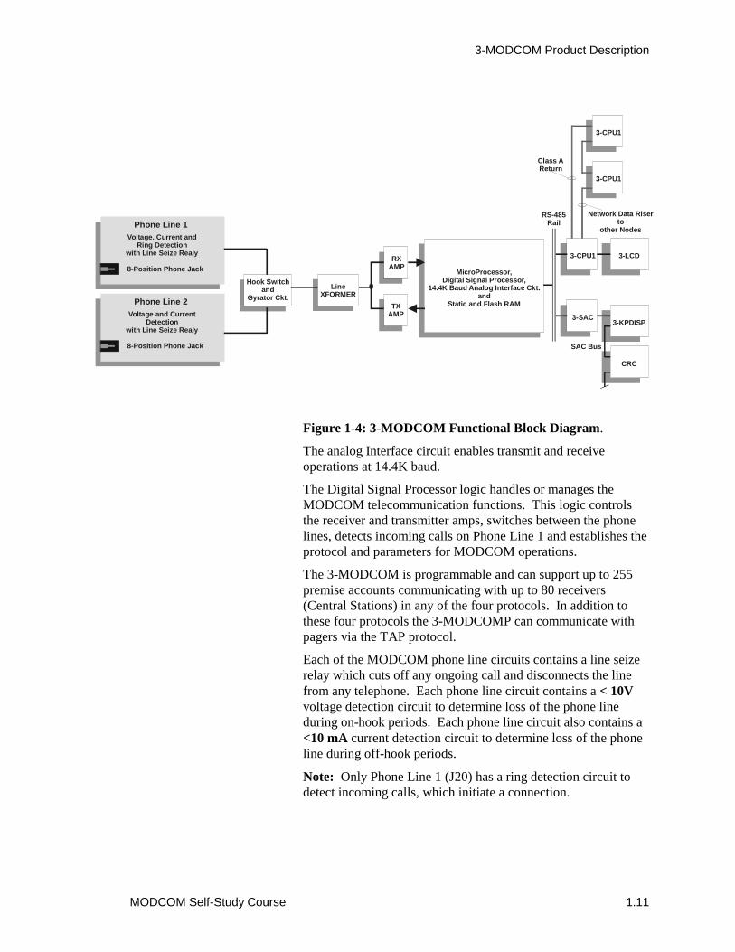
Figure 1-4: 3-MODCOM Functional Block Diagram.
The analog Interface circuit enables transmit and receiveoperations at 14.4K baud.
The Digital Signal Processor logic handles or manages theMODCOM telecommunication functions. This logic controlsthe receiver and transmitter amps, switches between the phonelines, detects incoming calls on Phone Line 1 and establishes theprotocol and parameters for MODCOM operations.
The 3-MODCOM is programmable and can support up to 255premise accounts communicating with up to 80 receivers(Central Stations) in any of the four protocols. In addition tothese four protocols the 3-MODCOMP can communicate withpagers via the TAP protocol.
Each of the MODCOM phone line circuits contains a line seizerelay which cuts off any ongoing call and disconnects the linefrom any telephone. Each phone line circuit contains a < 10Vvoltage detection circuit to determine loss of the phone lineduring on-hook periods. Each phone line circuit also contains a<10 mA current detection circuit to determine loss of the phoneline during off-hook periods.
Note: Only Phone Line 1 (J20) has a ring detection circuit todetect incoming calls, which initiate a connection.
Hook Switchand
Gyrator Ckt.
8-Position Phone Jack
Phone Line 1
3-CPU1 3-LCD
3-SAC3-KPDISP
RS-485Rail
MicroProcessor,Digital Signal Processor,
14.4K Baud Analog Interface Ckt.and
Static and Flash RAM
SAC Bus
RXAMP
TXAMP
LineXFORMER
Voltage, Current andRing Detection
with Line Seize Realy
8-Position Phone Jack
Phone Line 2Voltage and Current
Detectionwith Line Seize Realy
CRC
3-CPU1
3-CPU1
Network Data Riserto
other Nodes
Class AReturn

3-MODCOM Product Description
1.12 MODCOM Self-Study Course
Up to 10 MODCOM modules can be installed within anetworked EST3 system. These can be in a single node ordistributed throughout the network nodes. Multiple MODCOMsare used to provide redundant communications with the CentralStation, as a backup for critical communications links and/or toprovide dedicated security transmission hardware.
When using multiple MODCOMs for redundantcommunications both are configured and programmed totransmit the same messages to different receivers at a CentralStation or to different receivers at different Central Stationlocations.
MODCOM modules can be configured and programmed tobackup one another. In this way, Central Station or paging(TAP) communications is guaranteed. Using backup configuredMODCOM modules enables you to create a dynamic failoveroperation. This means that when a communication failure ortrouble occurs on one of the MODCOMs, the EST3 systemswitches from accounts on the MODCOM in trouble tomatching accounts on its backup MODCOM.
A dedicated Central Station dialer MODCOM can be configuredand programmed in multiple tenant integrated systemapplications where there may be a high volume of AccessControl and Keypad Display modem traffic. In this case, thefirst MODCOM may be used for this modem communications(Access Control and Keypad Display Data) and the second maybe used for Central Station dialer communications.
3-MODCOM Product Description
MODCOM Self-Study Course 1.13
Configuring the MODCOMYou use the 3-SDU System Definition Utility to create therequired configuration parameters, properties and data for thespecific application where the MODCOM is to be used. Afterthe MODCOM configured database is completed in the 3-SDU,you convert it to a binary file and download it into theappropriate MODCOM.
CAUTION: The 3-MODCOM and 3-MODCOMP modules areconfigured and programmed using EST3 3-SDU version 3.0 orhigher. Do not attempt to use these modules with earlierversions of the SDU or with non-compatible 3-CPU1 microcode.
Once configured, the MODCOM database application is storedin the 3-MODCOM and 3-MODCOMP nonvolatile memory.This database determines the operational parameters for yourapplication’s 3-MODCOM or 3-MODCOMP. Such as, phoneline properties, receiver attributes, and account parameters. Thisdatabase includes transmission details, such as telephonenumbers and dialing options.
In fully integrated applications supporting fire, security andaccess control some security and access control data isdownloaded to and stored onboard the MODCOM.
As previously stated, the 3-MODCOM and 3-MODCOMP canbe configured as a 1-line dialer, 2-line dialer, modem only,modem and 1-line dialer, or modem and 2-line dialer.
WARNING: For UL listed fire and FM approved installations,the MODCOM must be configured as a 2-line dialer, where bothlines have line cut detection supervision.
The 3-MODCOM and 3-MODCOMP operate in accordancewith the configuration database and rules program downloadedinto the networked system’s 3-CPU1’s. Telephone numbers,dialing details, activation of the dialer test signal, and otherMODCOM parameters are configured data which must bedownloaded into the MODCOM for proper operation for yourspecific application.
In order for the MODCOM to electronically dial the CentralStation, specific dialer parameters must also be configured in the3-SDU. These include whether you are using pulse or tonedialing, the Central Station telephone number(s), and periodictest transmission parameters required for fire alarm installations.
After the configuration process is complete, the SDU providesyou with a report of all Central Station codes on an accountbasis that can be transmitted from the MODCOMP. This reportshould be given to the appropriate Central Station.
3-MODCOM Product Description
1.14 MODCOM Self-Study Course
MODCOM Dialer Transmission ProcessThe multiple MODCOM, multiple phone line and multipletelephone features of the 3-MODCOM and 3-MODCOMPprovide a high level of transmission integrity. The MODCOMis designed to ensure that the call to the Central Station getsthrough.
Figure 1-5 shows a flow diagram of the Dialer TransmissionProcess. The sequence for MODCOM to Central Stationcommunications follows:
1. When an event occurs within the EST3 system that is to bereported to the Central Station, the MODCOM seizes one ofthe predetermined telephone lines.
2. The MODCOM puts the seized line on-hook for threeseconds to cut off any ongoing call and to disconnect theline from any telephone or dialing device that may beconnected down-line.
Note: The MODCOM makes two attempts to select an unusedline before seizing a line already in use.
3. The MODCOM takes the seized line off-hook and waits fora dial tone. If a dial tone is not detected within apredetermined time established during configuration, theMODCOM puts the line on-hook, increments an attemptcounter and continues to alternate lines and preconfiguredphone numbers until a dial tone is detected.
For example, if the MODCOM has been configured with twotelephone numbers and only one telephone line, it makes fourattempts to connect using the first number then four attemptsusing the second number. This alternation between these twotelephone numbers continues until a connection is made orpreconfigured maximum number of attempts has been achieved.
Note: The DS1 and DS2 LEDs light steady during the off-hookperiods when data is not being transferred.
4. After achieving a connection (dial tone detection), theMODCOM dials the Central Station using thepreprogrammed and preconfigured dialing mode andtelephone number.
5. The MODCOM then waits 40 seconds for a handshakingmessage from the Central Station indicating that aconnection with the Central Station has been achieved.
3-MODCOM Product Description
MODCOM Self-Study Course 1.15
6. If handshaking is not received within the 40-second period,the MODCOM puts the line on-hook, waits for apreconfigured period of time and then repeats steps 3through 5. If handshaking is detected the MODCOMproceeds to step 9.
7. If the MODCOM is still unable to contact the CentralStation receiver within a second 40-second period it seizesthe other telephone line and makes two attempts to detecthandshaking on it.
8. If the MODCOM is still unable to contact a Central Stationreceiver, it reseizes the first telephone line and repeats thetwo attempts to reach the Central Station receiver using apreconfigured secondary telephone number. If handshakingis detected the MODCOM proceeds to step 9.
Note: If the MODCOM is still unable to contact the CentralStation receivers, it repeats steps 6 through 8, alternatingtelephone lines and numbers until a preconfigured number ofattempts is achieved. On detecting the maximum number ofattempts the MODCOM sends a trouble message to the EST3system’s 3-CPU1.
Note: The MODCOM retries the full number of attempts ifanother event occurs or one attempt for the existing event if thepreconfigured Wait Time On-Hook Between Attempts ToSame Number period expires.
9. When a connection is completed, ringing is detected by theCentral Stations dialer receiver, which goes off-hook andtransmits the required handshaking.
10. If the handshaking received by the MODCOM matches thepreconfigured format, the MODCOM transmits all premisesevent data in the predetermined format (Contact ID, SIA, 4/2or 3/1).
Note: The DS1 and DS2 LEDs flash rapidly during datatransmissions.
11. The MODCOM then waits for acknowledgement and shutdown signal handshaking (called a KISSOFF) from theCentral Station receiver. On receiving this KISSOFFhandshaking the MODCOM puts the telephone line on-hook, ending the call.
Note: The DS1 and DS2 LEDs extinguish.

3-MODCOM Product Description
1.16 MODCOM Self-Study Course
MODCOMputs line on-hook,
ending call.
PredefinedEvent
Activation
UnusedLine
?
SecondAttempt
?
YES
NO
YES
NO
SeizePredeterminedTelephone Line
Put line On-hookfor 3 seconds to
disconnectongoing calls
Put line Off-hookand
check for Dial Tonefor configured period
DialTone
?
YES
NO Put line On-hookand
incrementattempt counter
MaximumAttempts
?
YES Send Troubleto
3-CPU1/3-LCD
NO
Alternate Lineor Phone Number
andtry again
Dial Central Stationand
Wait 40 secondsfor handshaking
YES
NOHandshaking
Received?
HandshakingReceived
?
SecondTry?
NO
IncrementAttempt Counter
andWait Time Between
Attempts
YES
Alternate Lineor Phone Number
andtry again
MaximumAttempts
?
NO
YESSend Troubleto
3-CPU1/3-LCDHandshaking
Match?
YES
NO Send Troubleto
3-CPU1/3-LCD
MODCOMTransmits premises
event data toCentral Station
ExecuteConfirmation
Rule on Activationof Command List
KISSOFFAcknowledged
?
ConfirmationCommand
List?
NO
NO
YES
YES
Figure 1-5: 3-MODCOM Transmission Process FlowDiagram.
3-MODCOM Product Description
MODCOM Self-Study Course 1.17
12. In the more sophisticated Access Control and Securityintegrated applications it is sometimes desired to initiatepremise notification (security alarm) after the CentralStation has confirmed receipt of the event. In this way, theCentral Station can respond to the event before possiblewarning the intruder. In this case, you would haveconfigured a Command List object for this KISSOFFconfirmation. You would then write a rule where thisConfirmation Command List would activate on receipt ofKISSOFF (dotted lines). This Confirmation Command List’sactivation would then execute the rule for premisenotification.
Advanced Access Control and Security applications are beyondthe scope of this self-study course and are covered in the EST3Synergy Enabled® Certification course. For this lesson which isfor fire only applications, on receiving this KISSOFFhandshaking, the MODCOM puts the telephone line on-hook,ending the call.

3-MODCOM Product Description
1.18 MODCOM Self-Study Course
Programming the MODCOMAs previously stated, the 3-MODCOM and 3-MODCOMPmodules are very flexible dialer/modem modules used to supporta wide variety of applications. These modules are not plug-and-play and require some level of preconfiguration andprogramming to support your specific modem/dialerrequirements. Before attempting to configure and program theMODCOM you should communicate with the Central Station togather the required parameters and protocol requirements beforeyou begin using the 3-SDU.
In the case of dialer applications, you need to identify the levelof event reporting for your application. For this self-studycourse we will discuss three levels of event reporting to aCentral Station.
The first is GENERAL reporting which is basic and thesimplest event reporting method. In this case, event reporting isnormally limited to fire-only applications and the followingevents are reported:
1. General alarm activation and restoration.
2. General supervisory activation and restoration.
3. General trouble activation and restoration.
Note: Phone line troubles, AC power failure troubles, etc. arereported as a general troubles to the Central Station. If moredetailed trouble event reporting is desired you will need to useZONE or POINT reporting techniques. When the AC PowerDelay is configured, an AC Power Failure event will report afterthe preset delay, but only as a general trouble.
4. Low Battery or Dead Battery Trouble (pseudo pointBATT_TRBL_CC_SS) activation and restoration.
Where CC is the cabinet address and SS is themonitor module slot location.
5. Communication Trouble activation and restoration.
Note: This Communication trouble is not a MODCOM pseudopoint listed in the SDU objects. Comm Trouble reporting is builtinto the MODCOM microcode software and all you need to dois create the coded event message to be sent.
In security applications to report Security Perimeter, SecurityInterior, and Holdup alarms you will need to use ZONE orPOINT reporting techniques.
3-MODCOM Product Description
MODCOM Self-Study Course 1.19
In general reporting you simply report the event code to theCentral Station and are not required to report ZONE or POINTevents. What is important here is to resolve MODCOMoperating parameters and Central Station receiver, account,telephone line/number, and communications protocol issuesbefore the configuration and programming process begins.
The second method is ZONE reporting. In this case, thepremises reporting to the Central Station is subdivided intozones or areas. You are required to support event reportingsimilar to that described for general, but this time on a zone-by-zone or area-by-area basis. Now when you report the event codeto the Central Station you would send the event code and a zoneor area identifier (location) code.
The third method is POINT reporting. This method requiresthat enhanced communication protocols be used. In this case,the MODCOM must report the event status and identity of everydevice or point within the premises. This method is called pointreporting because every point within the system that goes intofire Alarm, security Alarm, trouble or supervisory activation andthe restoration of each can be reported to the Central Station.This reporting would be in the order of occurrence and priority.Now when you report the event code to the Central Station youwould also send a system point identification code.
Note: The more sophisticated ZONE and POINT event reportingmethods are beyond the scope of this self-study course. Thesemethods are presented in the EST3 Synergy Enabled®
Certification Course.
In any of the three methods of event reporting the MODCOMmust be configured to support the required operation and rulesmust be written to report event activation and restoration to theCentral Station.
You will also need to specify Central Station receivers, accountsand telephone numbers prior to programming your application.
A Central Station receiver is the logical destination at theCentral Station to which the MODCOM must connect andsubsequently transmit event status messages to. A CentralStation may have many receivers in operation, each capable ofreceiving many calls. The Central Station will determine whichreceiver and telephone number you use for each account.
3-MODCOM Product Description
1.20 MODCOM Self-Study Course
During the configuration process you will need to:
� Label each receiver specified.
� Create a description of each receiver’s purpose.
Note: For Central Station purposes, the telephone number usedto gain access to a specified receiver basically identifies thereceiver. It may be critical to your application to enter relevantCentral Station information for the receiver being configured inthis description field for your reference.
� Configure telephone line properties.
� Enter your dial-in telephone number.
� Enter the auto-answer ring cycle count.
� Enter the wait time to detect dial tone.
� Enter the wait time for calling party disconnect.
� Enter the wait time for line cut monitor sensing.
� Enter the primary and secondary Central Stationreceiver telephone numbers.
� Identify the protocol used for event reporting.
� Enter the maximum number of dial attempts.
� Enter the on-hook wait time between dial attempts.
An account within the MODCOM links the end user to aspecific Central Station receiver, identifying the user sitesending the event code and the Central Station to which themessage is being sent. Each event message sent by theMODCOM includes an account number. During theconfiguration process you will need to:
� Label each account specified.
� Create a description of each account.
� Specify by label the Central Station where thisaccount is to be used.
� Enter the Central Station account number.
� Enter the dial test interval and/or time of day.
Note: Several accounts may share the same Central Stationreceiver.
3-MODCOM Product Description
MODCOM Self-Study Course 1.21
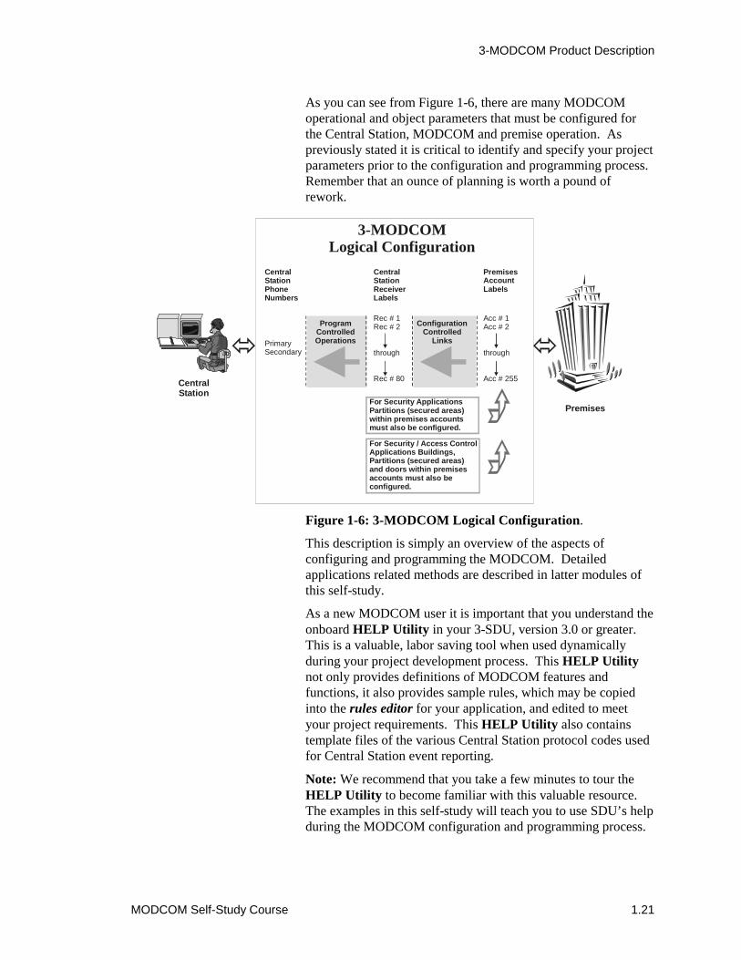
As you can see from Figure 1-6, there are many MODCOMoperational and object parameters that must be configured forthe Central Station, MODCOM and premise operation. Aspreviously stated it is critical to identify and specify your projectparameters prior to the configuration and programming process.Remember that an ounce of planning is worth a pound ofrework.
Figure 1-6: 3-MODCOM Logical Configuration.
This description is simply an overview of the aspects ofconfiguring and programming the MODCOM. Detailedapplications related methods are described in latter modules ofthis self-study.
As a new MODCOM user it is important that you understand theonboard HELP Utility in your 3-SDU, version 3.0 or greater.This is a valuable, labor saving tool when used dynamicallyduring your project development process. This HELP Utilitynot only provides definitions of MODCOM features andfunctions, it also provides sample rules, which may be copiedinto the rules editor for your application, and edited to meetyour project requirements. This HELP Utility also containstemplate files of the various Central Station protocol codes usedfor Central Station event reporting.
Note: We recommend that you take a few minutes to tour theHELP Utility to become familiar with this valuable resource.The examples in this self-study will teach you to use SDU’s helpduring the MODCOM configuration and programming process.
CentralStation
Premises
3-MODCOMLogical Configuration
CentralStationPhoneNumbers
CentralStationReceiverLabels
PremisesAccountLabels
PrimarySecondary
Rec # 1Rec # 2
through
Rec # 80
Acc # 1Acc # 2
through
Acc # 255
ProgramControlledOperations
ConfigurationControlled
Links
For Security ApplicationsPartitions (secured areas)within premises accountsmust also be configured.
For Security / Access ControlApplications Buildings, Partitions (secured areas)and doors within premisesaccounts must also beconfigured.

3-MODCOM Product Description
1.22 MODCOM Self-Study Course
To better understand developing applications which employ theMODCOM and applications which integrate Access Control andSecurity into the EST3 Life Safety System you need tounderstand the features and functions that have been added toversion 3.0 of the 3-SDU. A description of what’s new in theSDU follows.
The Command ListDuring MODCOM, Access Control and Security applications itmay be desired to branch to a sub-routine when an event occurs.
For example, Figure 1-7 shows a flow diagram of a rulesequence on an event’s activation. For the sake of this example,let’s assume that the event was a security alarm. In our example,we are using a Central Station service and the first output actionmight be to report this security alarm to this service. The secondoutput action might be to annunciate this security event at thesecurity office on the premises. The third output action maysend a message to a pager. The fourth output action may be toreport to the Central Station when the security intrusion has beenverified on the premises.
In our example, we also want to sound an on-premises securityalarm for a period of 3 minutes. We will due this by activating asubroutine from the last output command of our primary rule,which turns on a security bell, delays for 180 seconds and turnsthe security bell off.
Figure 1-7: Example Security Alarm Sequence.
EVENTACTIVATION
OUTPUTACTION
OUTPUTACTION
OUTPUTACTION
OUTPUTACTION
BRANCHON
EVENT
SUB-ROUTINEACTIVATION
OUTPUTACTION
DELAY
OUTPUTACTION

3-MODCOM Product Description
MODCOM Self-Study Course 1.23
This rule subroutine is executed on activation of an object in theSDU database called a Command List. A Command List is anEST3 object you create during the configuration process. EachCommand List object you create requires a unique label like anyother SDU database object.
To configure a Command List object you would simply selectConfigure and Command List from the SDU main menu bar.This would display the Manage Command Lists dialog boxshown in Figure 1-8. You then simply insert a Command Listobject, label it and create a meaningful description. For ourexample we will create a sound security bell command listobject. This command list will then be used to activate thepremise alarm bell on a security alarm.
Figure 1-8: Manage Command Lists Dialog Box.
It may be simpler to think of Command List objects as events,which activate within the EST3 application but do not fit intoother input device types or input event types. Such as, aSecurity Perimeter Alarm. In this case, the Security PerimeterAlarm is an event that is configured as a Command List devicetype with a unique label.

3-MODCOM Product Description
1.24 MODCOM Self-Study Course
In this way, a command list, when activated, executes asubroutine rule, as a normal rule, on activation of the predefinedsystem event. Where the input event type would beACTIVATION, the device type would be COMMANDLISTand Command List label is what you’ve assigned during theconfiguration process.
Assuming that we are reporting on a general alarm basis to theCentral Station and using Contact ID protocol, the rules for ourFigure 1-7 example may look like:
[Security Alarm Sequence]SECURITYALARM PARTITION ‘FLOOR1_WEST’:
SEND ‘XYZAcct1234’ MSG “ActivateEventCode”,
FAST ‘SecDesk_Flr1_Perimiter_LED’,
SEND ‘PageCo’ MSG “UserID$(CR)$Message”,
SEND ‘XYZAcct1234’ MSG “VerifyEventCode”,
ACTIVATE ‘Sound_Alarm_Bell’;
[Sound Alarm Bell Sequence]ACTIVATION ‘Sound_Alarm_Bell’:
ON ‘Floor*_SecurityBell’,
Delay 180,
OFF ‘Floor*_SecurityBell’;
As you can see, the integration of MODCOM, Access Controland Security into EST3 applications has created new InputEvents and Output Commands.
ACTIVATION – An Input Event that lets you detect apredefined Command List activation.
ACTIVATE – An Output Command that lets youactivate a command list from a rule and subsequentlyexecute a subroutine rule.
RESTORE – An Output Command that lets you restorea command list from a rule.
SEND – An output Command that lets you send amessage (predefined code) to a Central Station throughthe MODCOM when an event occurs.
Command Lists are used in advanced Access Control andSecurity applications. As previously stated, these integratedsystem applications are beyond the scope of this self-studycourse and are covered in the EST3 Synergy Enabled®
Certification Course.
3-MODCOM Product Description
MODCOM Self-Study Course 1.25
The Command QualifiersOn the surface the rules of the previous example look like theywill do the trick. However on closer examination we see thatthis is not the case.
From your previous experience with writing rules you shouldunderstand the rules activate sequentially (top-down) and restoresequentially (bottom-up). With this knowledge it is easy to seethat the primary rule reports to the Central Station on the ruleactivation and restoration, fast flashes the LED on activation andturns off the LED on restoration. The Command List alsoexecutes on the primary rules activation and restores during theprimary rules restoration, sounding the security bells for asecond 3-minute sequence.
In our example, we want to report the security alarm to theCentral Station and Pager Service during the rule’s activationsequence, report the security intrusion verification during rule’srestoration sequence and sound the security alarm bells onceonly during rule’s activation sequence. To accomplish this newbehavior for rules, command qualifiers have been added to thesyntax of rules.
A command qualifier is simply a + or – added to the commandof a rules output statement. A + causes the command to executeonly on a rule’s activation. The – causes the command toexecute only on a rule’s restoration. As shown below, by addingthe appropriate command qualifiers to our example rules we cancontrol when we want the commanded actions to occur.
[Security Alarm Sequence]SECURITYALARM PARTITION ‘FLOOR1_WEST’:
+SEND ‘XYZAcct1234’ MSG “ActivateEventCode”,
FAST ‘SecDesk_Flr1_Perimiter_LED’,
+SEND ‘PageCo’ MSG “UserID$(CR)$Message”,
-SEND ‘XYZAcct1234’ MSG “VerifyEventCode”,
+ACTIVATE ‘Sound_Alarm_Bell’;
[Sound Alarm Bell Sequence]ACTIVATION ‘Sound_Alarm_Bell’:
ON ‘Floor*_SecurityBell’,
Delay 180,
OFF ‘Floor*_SecurityBell’;
These rules now report to the Central Station at the appropriatetime and sound the security alarm bell once. These rules couldhave been written as follows and still sounded the security alarmbells once.
3-MODCOM Product Description
1.26 MODCOM Self-Study Course
[Security Alarm Sequence]SECURITYALARM PARTITION ‘FLOOR1_WEST’:
+SEND ‘XYZAcct1234’ MSG “ActivateEventCode”,
FAST ‘SecDesk_Flr1_Perimiter_LED’,
+SEND ‘PageCo’ MSG “UserID$(CR)$Message”,
-SEND ‘XYZAcct1234’ MSG “VerifyEventCode”,
ACTIVATE ‘Sound_Alarm_Bell’;
[Sound Alarm Bell Sequence]ACTIVATION ‘Sound_Alarm_Bell’:
+ON ‘Floor*_SecurityBell’,
+Delay 180,
+OFF ‘Floor*_SecurityBell’;
Note: It’s important to note here that the Central Stationmessages used in this example are created for ease ofunderstanding and are not the actual coded messages sent to theCentral Station or Pager. Detailed codes for the variousprotocols used for MODCOM communications will be describedlater in this self-study course. Detailed templates for EST3supported protocols are provided in you onboard HELP Utility.
Numerical Indexing or N-VariablesNumerical Indexing (N-Variables), prior to 3-SDU release 3.0,was used to simplify writing rules. A numerical index wasalways used in the input side of a rule to specify specificnumbers, ranges of numbers or combinations of numbers andranges in the rule’s input object label. For example:
A number - <N:#>
A range - <N:#-#>
A combination - <N:#,#-#,#,#-#>
A Numerical Calculator or Operator could then be used in arule’s output object label to determine which output objectswere to be activated.

3-MODCOM Product Description
MODCOM Self-Study Course 1.27
For example the rule:
[Alarm Notification]ALARM ‘FLOOR<N:1-9>*’:
AMPON ‘Floor<N>_AMP’ TO ‘EVAC’,
AMPON ‘Floor<N+1>_AMP’ TO ‘EVAC’,
AMPON ‘Floor<N-1>_AMP’ TO ‘EVAC’,
AMPON ‘Floor*_AMP’ TO ‘ALERT’,
ON ‘Floor<N>_STB’,
ON ‘Floor<N+1>_STB’,
ON ‘Floor<N-1>_STB’;
broadcasts default EVAC messages to the floor of incident, floorabove and floor below and turns on the strobes to the samefloors. A default ALERT message is broadcast to all otherfloors.
Prior to release 3.0, the numerical index would not recognize aleading 0. For example, if the previous rule was for a 25-storybuilding where the floors were labeled Floor01 through Floor25,you could not use the label ‘Floor<N:01-25>*’ in theinput statement. This rule would not include any object forfloors 01 through 09. Prior to release 3.0 you would havewritten two rules, one labeled ‘Floor0<N:1-9>*’ and theother labeled ‘Floor<N:10-25>’.
CAUTION: You can write the label ‘Floor*<N:1-25>*’and make it work. However, the * prior to the numerical indexwill include all variable modifiers between Floor and the<N:1-25>. Which may include undesired input objects inthe rule. The bottom line is to take caution when using awildcard (*).
3-SDU release 3.0 or greater provides an additional function tothe numerical index and numerical calculator or pperator used inthe input and output object labels. Now you can specify theminimum number of digits or width to be used in the numericalindex within the rule. The syntax would be:
Input Object Label: <N:#-#:W>
Output Object Label: <N:W>
where W is the minimum number of digits or width of the index.The default is 1.

3-MODCOM Product Description
1.28 MODCOM Self-Study Course
This accepts the 0 of the 1 through 9 index numbers. Now youcan write the rule for the 25-story building in one rule:
[Alarm Notification]ALARM ‘FLOOR<N:1-25:2>*’:
AMPON ‘Floor<N:2>_AMP’ TO ‘EVAC’,
AMPON ‘Floor<N+1:2>_AMP’ TO ‘EVAC’,
AMPON ‘Floor<N-1:2>_AMP’ TO ‘EVAC’,
AMPON ‘Floor*_AMP’ TO ‘ALERT’,
ON ‘Floor<N:2>_STB’,
ON ‘Floor<N+1:2>_STB’,
ON ‘Floor<N-1:2>_STB’;
Substitution StringsIntegrated MODCOM, Access Control and Security applicationsthat require the EST3 System to report to the Central Stationhave created new requirements for the EST3 applications tools.As previously discussed, the EST3 System can report events to aCentral Station and/or pager in one of five protocols: ContactID, SIA, 4/2, 3/1 and TAP.
The requirements of the Central Station or Pager Service that theEST3 system is communicating with will determine the protocolto be used for these communications. It is critical that theserequirements be determined prior to the configuration andprogramming process.
These coded messages may be numerical or alphanumericalASCII text. In either case, they contain relevant information tosupport monitoring premises status. After determining theprotocol to be used, you need to determine the coded messagecontent required by the monitoring service. The structure ofthese coded messages varies from one monitoring service toanother.
The 3-SDU provides a substitution string function that enablesyou to tailor communications to match the monitoring servicerequirements. For example, in all protocols, sending account,user ID and event codes information would be required.However, frequently it may be desired to send the time and thedate of the event being reported or other information.
3-MODCOM Product Description
MODCOM Self-Study Course 1.29
The syntax for a Substitution String is:
$(Alphanumeric ASCII Field)
where the dollar sign $ indicates that a substitution stringfollows. The actual substitution message data is enclosed in theparenthesis (( )).
Figure 1-9 shows examples of using a Substitution String in arule. In the SIA DCS protocol example, if any of the smokes onFloors 1 through 7 go into alarm, you send the fire alarm event(FA<N>) for the specific floor to the for the specified accountto the Central Station’s specified receiver. By using thesubstitution string function, you also send the date and time ofthe event.
It is important to note here that the available Substitution Stringsfor the SIA DCS protocol are:
� $(TIME) inserts the default 24-hour clock time.
� $(DATE) inserts the default MMDDYY dateformat.
� $(USER) inserts the user identification code.
Note: As shown in Figure 1-9, the substitution stringsmust be entered into the message before the event(FA<N> in our example).
� $(USERID) inserts the user identification codeand a qualifier (i.e. pin number for individualidentification). USER ID differs from USER in thatit sends a lower case id with the pin number.
Note: USER and USER ID numbers are configured inthe Access Control Database software used for EST3Synergy Enabled® Access Control applications. Thesewould be pin numbers of individuals approved for entryinto a protected premise. For example, if you wanted toreport the individual pin number access was granted foryou would use an access granted event type (DG) andthe User ID substitution string:
“DG$(USERID)”
SIA DCS substitution conventions are described in detail inModule 3 of this self-study.
3-MODCOM Product Description
1.30 MODCOM Self-Study Course
In the TAP protocol example, if any of the smokes on Floors 1through 7 go into alarm, you send the pager ID and fire alarmevent to the specified pager via the pager service. Again, byusing the Substitution String you also send the carriage return$(CR) which separates the pager ID and message, the date,time and specific location of the event $(LOCATION:M-N).
It is important to note here that the available Substitution stringsfor the TAP protocol are:
� $(TIME) inserts the default 24-hour clock time.
� $(TIME12) inserts the 12-hour clock time.
� $(TIME24) inserts the 24-hour clock time.
� $(DATE) inserts the default MM-DD-YY dateformat.
� $(MMDDYY) inserts the MM-DD-YY dateformat.
� $(MMDDYYYY) inserts the MM-DD-YYYYdate format.
� $(DDMMYYYY) inserts the DD-MM-YYYYdate format.
� $(USER) inserts the user identification code.
� $(CR) inserts a carriage return used to separate theUser ID and the event message.
� $(“) inserts a quotation mark.
� $(LOCATION) inserts the location text from thecorresponding objects 42-character message field.
Note: Remember that the maximum number orcharacters that can be included into a TAP message,including the User ID and other Substitution Strings, is59.
3-MODCOM Product Description
MODCOM Self-Study Course 1.31
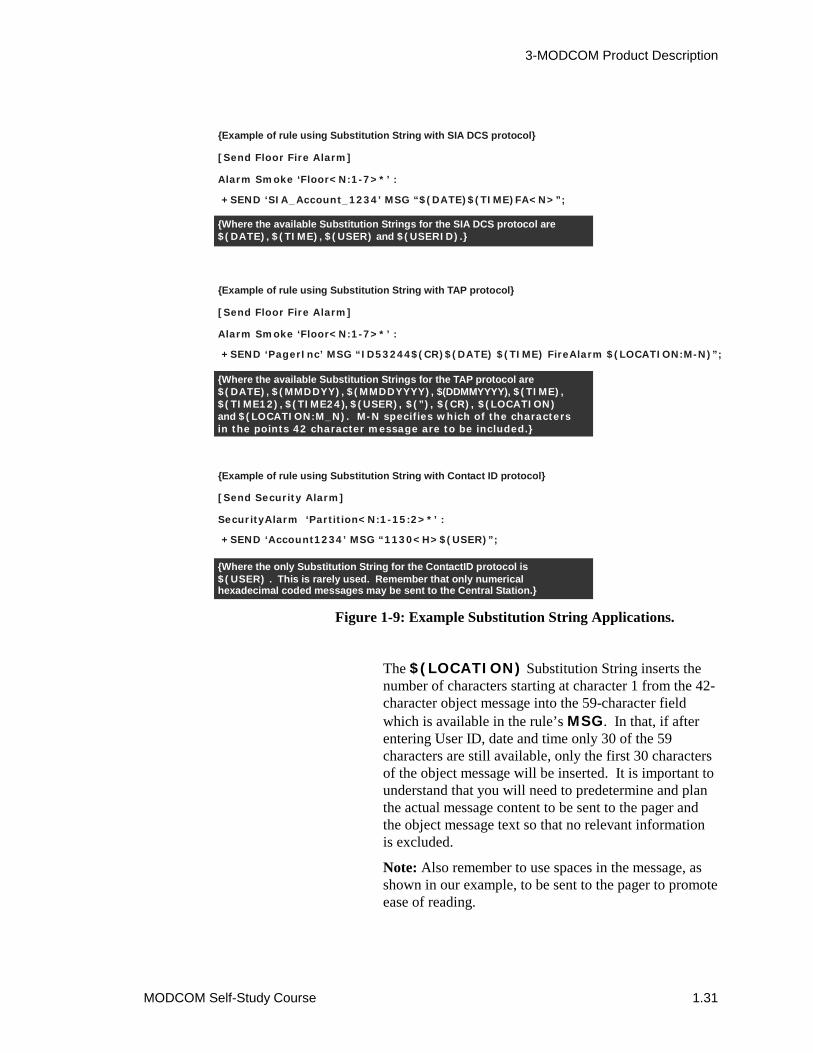
Figure 1-9: Example Substitution String Applications.
The $(LOCATION) Substitution String inserts thenumber of characters starting at character 1 from the 42-character object message into the 59-character fieldwhich is available in the rule’s MSG. In that, if afterentering User ID, date and time only 30 of the 59characters are still available, only the first 30 charactersof the object message will be inserted. It is important tounderstand that you will need to predetermine and planthe actual message content to be sent to the pager andthe object message text so that no relevant informationis excluded.
Note: Also remember to use spaces in the message, asshown in our example, to be sent to the pager to promoteease of reading.
+SEND ‘PagerInc’ MSG “ID53244$(CR)$(DATE) $(TIME) FireAlarm $(LOCATION:M-N)”;
{Example of rule using Substitution String with SIA DCS protocol}
[Send Floor Fire Alarm]
Alarm Smoke ‘Floor<N:1-7>*’ :
+SEND ‘SIA_Account_1234’ MSG “$(DATE)$(TIME)FA<N>”;
{Example of rule using Substitution String with TAP protocol}
[Send Floor Fire Alarm]
Alarm Smoke ‘Floor<N:1-7>*’ :
{Example of rule using Substitution String with Contact ID protocol}
[Send Security Alarm]
SecurityAlarm ‘Partition<N:1-15:2>*’ :
+SEND ‘Account1234’ MSG “1130<H>$(USER)”;
{Where the available Substitution Strings for the SIA DCS protocol are, , and }$(DATE) $(TIME) $(USER) $(USERID).
{Where the available Substitution Strings for the TAP protocol are, , , $(DDMMYYYY), ,
, ), and
}
$(DATE) $(MMDDYY) $(MMDDYYYY) $(TIME)$(TIME12) $(TIME24 $(USER), $(”), $(CR), $(LOCATION)
$(LOCATION:M_N). M-N specifies which of the charactersin the points 42 character message are to be included.
{Where the only Substitution String for the ContactID protocol is . This is rarely used. Remember that only numerical
hexadecimal coded messages may be sent to the Central Station.}$(USER)
3-MODCOM Product Description
1.32 MODCOM Self-Study Course
� $(LOCATION:M-N) inserts the location textfrom a specified range of characters fromcorresponding objects 42-character message field.
Where: M specifies the 1st character of a range ofcharacters from the 42-character object messagefield to be that is to be included in the eventmessage and N is the last character of the range tobe included in the event message.
Note: M must be greater than 0 and less than N.
For the Contact ID protocol example, it is important tounderstand that a hexadecimal coded message is sent to theCentral Station, which may specify the event, partition anddevice number. Rarely is the substitution string used to sendaddition information. In this example, each of the floors hasbeen configured into a partition. If any of the security alarmdevices within a partition in our example goes into alarm, yousend a event qualifier 1 for activation and the security alarmevent 130<H> specifying the partition to the specified CentralStation account (receiver). In this case the substitution string isused to also send the user ID.
Note: Remember that in Contact ID hexadecimal codedmessages are sent to the Central Station. You need to verifywith the Central Station provider the code requirements of yourapplication. Sending information that the Central Station is notequipped to use is meaningless.
In all three example cases, the Central Station account or Pageraccount destination is specified by its label after the SENDcommand and is enclosed in ‘ ‘. MSG specifies that themessage follows, which in enclosed in “ “.
Hexadecimal Indexing or H-Variables3-SDU release 3.0 or greater also offers hexadecimal indexing(H-Variables), which operate similar to numerical indexing.This feature enables you to incorporate base16 hexadecimalnumbers into your labels or coded messages to be sent to theCentral Station. This is a critical feature when using the ContactID protocol to report to a Central Station.
Like the numerical index, a hexadecimal index is used in theinput side of a rule to specify specific numbers, ranges ofnumbers or combinations of numbers and ranges in the rulesinput object label.
3-MODCOM Product Description
MODCOM Self-Study Course 1.33
For example:
A number: <H:#16>
A range: <H:#16-#16>
A combination: <H:#16,#16-#16,#16,#16-#16>
A hexadecimal calculator or operator can be used in a rulesoutput object label to determine which output objects areactivated. Also like numerical indexing you can specify theminimum number of digits (W) within the hexadecimal index:
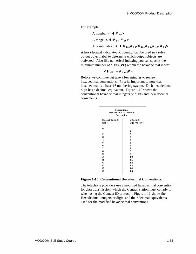
<H:#16-#16:W>
Before we continue, let take a few minutes to reviewhexadecimal conventions. First its important to note thathexadecimal is a base-16 numbering system. Each hexadecimaldigit has a decimal equivalent. Figure 1-10 shows theconventional hexadecimal integers or digits and their decimalequivalents.
Figure 1-10: Conventional Hexadecimal Conventions.
The telephone providers use a modified hexadecimal conventionfor data transmission, which the Central Station must comply towhen using the Contact ID protocol. Figure 1-11 shows theHexadecimal integers or digits and their decimal equivalentsused for the modified hexadecimal conventions.
ConventionalHexadecimal vs Decimal
Correlation
HexadecimalDigit
0123456789ABCDEF
DecimalEquivalent
0123456789101112131415

3-MODCOM Product Description
1.34 MODCOM Self-Study Course
Figure 1-11: Modified Hexadecimal Conventions forMODCOM applications.
Note: Observe that there is no hexadecimal A. You need toobserve these variations when using the H-variables. In that,sending a 01 or A1 is received as a 01 at the Central Station. Ifyou were not careful, two input points having hexadecimal ID’sof 01 and A1, respectively, would send only 01 to the CentralStation. This could create some confusion to the Central Stationprovider.
You can mix N-Variables and H-Variables within a rule. Thisfeature enables you to automatically convert from decimal tohexadecimal or from hexadecimal to decimal. For example thefollowing rule:
[Send Point ID Smoke Alarms]
Alarm Smoke ‘L1_SMK<N:1-15:2>’:
+SEND ‘Central’ MSG “FA<H>”;
sends a fire alarm event message to the Central Station whichincludes a hexadecimal code to identify the specific smokedetector on level 1 that went into alarm.
ModifiedHexadecimal vs Decimal
Correlation
HexadecimalDigit
0123456789B(*)C(#)DEF
DecimalEquivalent
101234567891112131415
3-MODCOM Product Description
MODCOM Self-Study Course 1.35
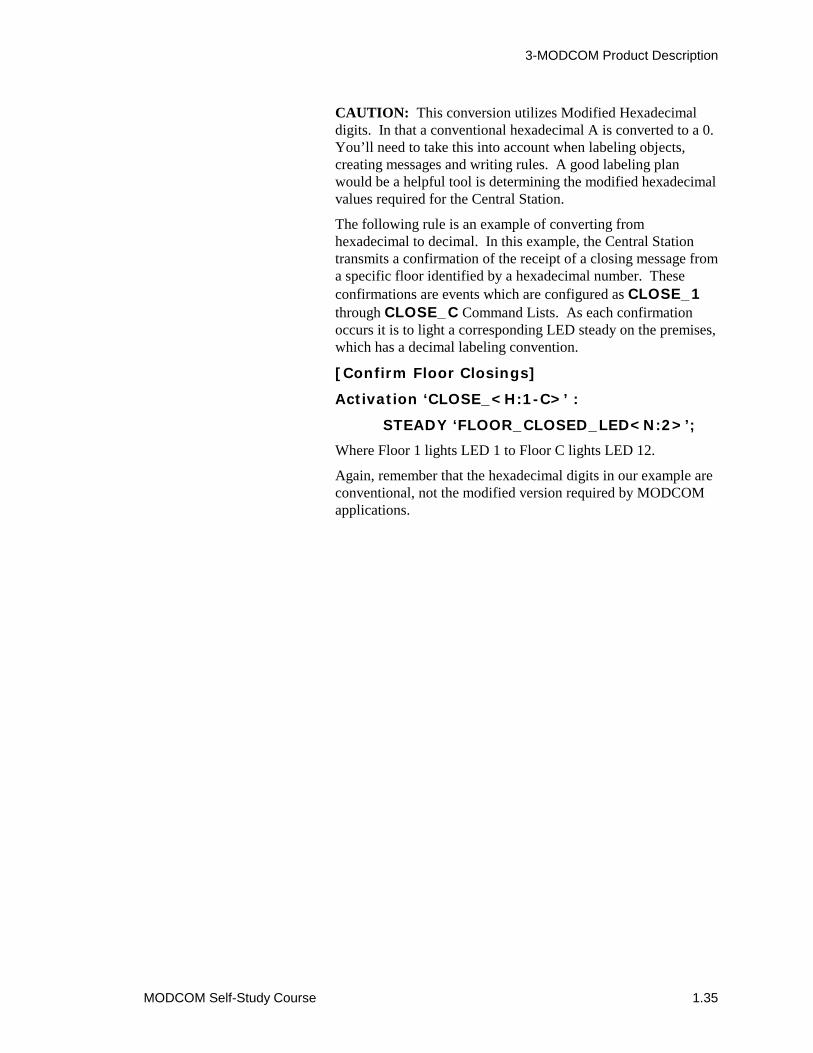
CAUTION: This conversion utilizes Modified Hexadecimaldigits. In that a conventional hexadecimal A is converted to a 0.You’ll need to take this into account when labeling objects,creating messages and writing rules. A good labeling planwould be a helpful tool is determining the modified hexadecimalvalues required for the Central Station.
The following rule is an example of converting fromhexadecimal to decimal. In this example, the Central Stationtransmits a confirmation of the receipt of a closing message froma specific floor identified by a hexadecimal number. Theseconfirmations are events which are configured as CLOSE_1through CLOSE_C Command Lists. As each confirmationoccurs it is to light a corresponding LED steady on the premises,which has a decimal labeling convention.
[Confirm Floor Closings]
Activation ‘CLOSE_<H:1-C>’ :
STEADY ‘FLOOR_CLOSED_LED<N:2>’;
Where Floor 1 lights LED 1 to Floor C lights LED 12.
Again, remember that the hexadecimal digits in our example areconventional, not the modified version required by MODCOMapplications.
3-MODCOM Product Description
1.36 MODCOM Self-Study Course
MODCOM Installation ConsiderationsTelephone Line RequirementsPrior to installing the 3-MODCOM or 3-MODCOMP you needto arrange for suitable TELCO lines and services. TheseMODCOM dialers can be used in most telephone lineapplications. The 3-MODCOM and 3-MODCOMP should notbe used in applications where:
� The Central Station telephone number(s) cannot bedialed directly and require operator assistance on thecall.
� Multiparty or party-line service exists.
� Operator assistance is required to complete a callwhere a foreign exchange (FX) connection cannotbe introduced.
� A connection cannot be established within 38seconds following the completion of dialing.
� An nonsupervised WATS or ground-startconnection is used.
These MODCOM dialers are compatible with any switcheddirect dialing (local) or direct distance dialing (DDD) telephonenetwork that does not require operator assistance.
The 3-MODCOM and 3-MODCOMP dialers prevent jammingby incoming calls when used with the Called Party Disconnecttelephone service option. In areas where Called PartyDisconnect is not available and jamming is a problem, aseparate, confidential, unlisted telephone number should be usedfor the MODCOM. Two unlisted telephone numbers, one foreach MODCOM telephone line, provide maximum dialerintegrity.
The 3-MODCOM and 3-MODCOMP must be connected to theincoming telephone line ahead of any other equipment (e.g.,telephones, answering machines, FAX machines) connected tothe phone line and immediately after the demarcation block.This requirement ensures that the MODCOM dialer circuit canseize the line during an alarm, disconnecting the otherequipment on the telephone line.
Other requirements:
1. Do not use a telephone line that is consideredessential for conducting the customers business.When possible use a separate, dedicated line forMODCOM use.

3-MODCOM Product Description
MODCOM Self-Study Course 1.37
2. When the input telephone line is composed of rotarytelephones, use the telephone line with the highesttelephone number for MODCOM connection tocreate the least interference with the customersbusiness telephone lines.
3. When the MODCOM connection is made to aTELCO (telephone) line also used for business,advise the customer that telephone service will bedisrupted for a few minutes during the MODCOMdialer connection periods.
4. In areas where connection must be made to thetelephone provider’s own connector blocks, theyshould be wired per the USOC RJ-31X or RJ-38Xconfiguration specified on the MODCOMinstallation sheet (P/N 387476).
5. When the MODCOM is configured as a two-linedialer the two incoming telephone lines must beused and connections must be made to each line.
Installing the MODCOM modulePrior to installing the 3-MODCOM or 3-MODCOMP into theEST3 chassis:
� Review your project requirements and sourceinformation for MODCOM parameters and theproper location where the MODCOM is to beinstalled on the EST3 chassis rail.
� Arrange for suitable TELCO lines and services perthe line requirements given above.
� Make sure the power is OFF on the cabinet wherethe MODCOM is to be installed.
To install the MODCOM module:
1. Use an anti-static wrist strap or equivalent to groundyourself while handling the MODCOM duringinstallation.
2. Carefully remove the MODCOM module from theanti-static bag or box that the module is packed in.This module is shipped with a blank door coverinstalled. Always handle this module by its edges orby this door.
3-MODCOM Product Description
1.38 MODCOM Self-Study Course
Note: Do not discard the anti-static carrier and shippingmaterials you received with the module. If a failure ordamage occurs, the module must be shipped back to thefactory in the anti-static packaging.
3. Place the anti-static bag on a flat surface and placethe module, with the modular phone jacks facing thetop, on this bag. Inspect the module for visibleshipping damage, turn it over and inspect the otherside for visible damage.
4. If a Control/LED display operator layer module is tobe installed, remove the blank front plate andassemble the Control/LED module membrane to itper installation sheet P/N 270493. Attach theControl/LED display module to the MODCOM viathe plastic standoffs and the ribbon cable provided.
5. Carefully plug the MODCOM module into thepredetermined rail position within the host cabinet.
CAUTION: Ensure that the module aligns with theplastic guide pins and seats firmly onto the railconnectors. These modules mount fairly easily onto therail. If you find that you have to force the module intoplace you are probably doing it wrong. In this case,inspect the rail connectors for bent pins and reinstall themodule carefully.
6. After you have ensured that the module is mountedproperly, fasten the module in place with its plasticpushpins.
Note: A special removal tool is provided with thecabinet that enables you to unsnap these pushpins whenit is desired to remove any module from its host chassis.
7. Restore power to the cabinet.
This completes the physical installation of the MODCOMmodules. You are now ready to connect the MODCOM to thefacility TELCO telephone lines, download its configuration andprogramming data, and test transmissions to the monitoringservice.

3-MODCOM Product Description
MODCOM Self-Study Course 1.39
Connecting the MODCOM to the TELCO linesPlug one end of the supplied 8-position modular telephonecable(s) to the appropriate TELCO line jack(s) on the top of theMODCOM module.
DO NOT plug the other end of the cable(s) into the RJ-31Xjack(s) until you have downloaded the MODCOM applicationsand are ready to test the system. This prevents interference withother normal customer traffic and equipment until you are readyfor the final connection and testing phase.
When you are ready for the final connection and testing phaseconnect the TELCO line jack(s) as follows:
J20 – Line 1 Jack J21 – Line 2 Jack
Single-line dialer Second line for two-line dialer
(or first line for two-line dialer)
Incoming Modem LineNote: NFPA 72 Fire Alarm System compliance requires that theMODCOM be connected to two loop-start telephone lines.When the s uses ground-start telephone lines, two loop-startlines must be installed for the dialer.
To determine the type of TELCO lines that are present onpremises:
1. Disconnect the phone line pair.
2. Connect the line pair to a test meter.
3. The meter will read between 48 to 52 Vdc betweenthe lines if it is equipped for loop-start.
4. The meter will read 0 Vdc between the lines, 48 to52 Vdc between one line and ground and 0 Vdcbetween the other line and ground if it is equippedfor ground-start.
Note: NFPA 72 Certified Fire Alarm System and Burglar AlarmSystem compliance requires that the TELCO telephone line beCalled Party Disconnect or Timed-Released Disconnect, whichpermit the MODCOM to seize the line when the TELCO line isin use.
To determine that the line is Called Party Disconnect havesomeone call the s from outside, hang up the premises telephonebut not the outside telephone, wait 40 seconds and then pick upthe premises telephone again. If the caller is still connected thesystem does not have Called Party Disconnect service.

3-MODCOM Product Description
1.40 MODCOM Self-Study Course
Module 1 evaluation
This concludes Module 1 of the 3-MODCOM Self-Study Course.Return to the objectives stated at the beginning of this module.Study them carefully to ensure that you are comfortable witheach objective. If not, return to that section and review it. Whenyou are satisfied, proceed to Module 2. You will be tested at theend of this self-study course.

MODCOM Self-Study Course 2.1
Module 2 Configuring the MODCOM
Summary
This self-study module introduces you to the procedures youmust employ to configure the 3-MODCOM and 3-MODCOMPinto an EST3 3-SDU application. This module defines anddescribes each MODCOM property or parameter that must beconfigured.
ContentIntroduction to module 2 • 2.2Key items • 2.3Objectives • 2.4Entering the MODCOM into a project • 2.5Configuring MODCOM General Operating Parameters• 2.9
To set the DACT Settings • 2.10To set the Public Service Telephone Network Settings • 2.11To set Line Properties • 2.12To set the Dial In Phone Number • 2.13To set MODCOM Timers and Counters • 2.14
Configuring MODCOM Receiver Properties • 2.16Insertin a MODCOM Receiver • 2.17Creating a Receievr Label and Description • 2.17Congiguring Receiver Phone Numbers and Protocol • 2.19To set the Receiver's Timer and Counter • 2.21To set the Receiver Default Messages • 2.22
Configuring MODCOM Account Properties • 2.25Creating an Account Label and Description • 2.26Selecting the Receiver, its Protocol and entering the CentralStation Account Number • 2.27Setting the Dial Test Timer Parameters • 2.29
Module 2 evaluation • 2.31
3-MODCOM Configuration
2.2 MODCOM Self-Study Course
Introduction to module 2This module covers the procedures required to configure boththe 3-MODCOM and 3-MODCOMP into the 3-SDU database.This self-study module provides detailed instruction on enteringthe MODCOM into the database, selected its operationalproperties or parameters and setting the MODCOM timers andcounters to meet the needs of your specific application.
Also covered are the procedures for configuring Central Stationreceiver and premises account properties. Details ontransmission protocols for dialer application are covered inModule 3 of this self-study course. Descriptions onprogramming the many MODCOM applications are coveredlater in this course.
Configuring the MODCOM is an easy task of simply selectingthe desired properties from SDU dialog boxes. The MODCOMhas a default setup for NFPA 72 compliance built into the SDUsoftware. These default settings will handle a majority ofMODCOM applications.
This self-study will focus on basic fire only applications usingthe Contact ID protocol, which is the prevalent fire application,the MODCOM is used in. Although discussed in this course, themore sophisticated Security, Access Control and Keypad displayMODCOM applications are covered in the factory-based EST3Synergy Enabled® training Course.
Review the Configure Projects, Cabinets, LRMs, and MODCOMtopics in your 3-SDU, Version 3.0 HELP Utility. You can getto the HELP utility through the 3-SDU or from your OnlineSupport Tools CD, release 4.0 or later.
Prior to starting this module and the remainder of this self-studycourse, install or upgrade the 3-SDU to version 3.0 or greater. Itis recommended that you create a practice project that you candevelop during these lessons. As each step of the MODCOMconfiguration and programming process is covered, you canpractice what you have learned in your practice project. Havingyour project open during this lesson will make the HELP utilityreadily available for you reference.
Associated study
Use the following technical reference manuals as associatedstudy material for this module:
• EST3 Installation and Service Manual, P/N 270380, Rev 4.0 orlater)
• Modem Communicator 3-MODCOM/3-MODCOMP InstallationSheet, (P/N 387476)
3-MODCOM Configuration
MODCOM Self-Study Course 2.3
Key itemsKey points to look for:
• NFPA 72 Central Station, Remote Station compliance Mode• Fully Programmable Mode• Configuring MODCOM phone lines and supervision• Configuring MODCOM Counter and Timer properties• Available communications protocols• Configuring Central Station Receiver properties• Configuring premise Account properties• Default message types
Key terms and operations to learn:
• Override Answering Machine• Default Dialing Methods• Ring Cycle Types• Calling Party Disconnect• Ring Cycle Count• Line Cut Monitoring• Tone vs. Pulse dialing• Contact ID protocol• SIA DCS, 3/1 and 4/2 protocols• TAP protocol• CMS Account numbers• Dial Test Timer settings
3-MODCOM Configuration
2.4 MODCOM Self-Study Course
ObjectivesUpon completion of this module you will be able to:
1. Configure the 3-MODCOM or 3-MODCOMP for the defaultNFPA 72 compliant or fully programmable operationalmode based on the requirements of your project.
2. Describe the relationship of Central Station Receivers andPremises Accounts within the MODCOM configurationprocess.
3. Create meaningful Receiver and Account labels anddescriptions.
4. Configure Central Station Receiver properties.
5. Configure Premise Account properties.
6. Describe the purpose and ranges for the various MODCOMCounters and Timers.

3-MODCOM Configuration
MODCOM Self-Study Course 2.5
Entering the MODCOM into a project
Review the Configure Projects, Cabinets, LRMs and MODCOMtopics in your 3-SDU, Version 3.0 HELP Utility. You can getto the HELP utility via the 3-SDU or from your Online SupportTools CD, release 4.0 or later.
Prior to starting this module and the remainder of this self-studycourse, install or upgrade the 3-SDU to version 3.0 or greater. Itis recommended that you create a practice project that you candevelop during these lessons. As each step of the MODCOMconfiguration process is covered, you can practice what you havelearned in your practice project. Having your project openduring this lesson will make the HELP utility readily availablefor you reference.
Entering the 3-MODCOM and 3-MODCOMP into your projectdatabase is an easy step-by-step process. After you have createda new project, configured the project parameters and configuredeach cabinet in your project, you simply enter the MODCOMinto the required slot of the cabinet in which it is to reside. Adescription of these steps follows.
To enter the MODCOM into your project, select Configure fromthe main menu and Cabinet from the drop-down menu as shownin Figure 2-1.
Figure 2-1: Select Configure and Cabinets.
3-MODCOM Configuration
2.6 MODCOM Self-Study Course
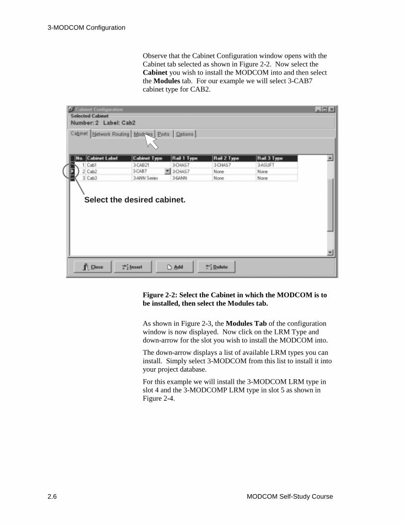
Observe that the Cabinet Configuration window opens with theCabinet tab selected as shown in Figure 2-2. Now select theCabinet you wish to install the MODCOM into and then selectthe Modules tab. For our example we will select 3-CAB7cabinet type for CAB2.
Figure 2-2: Select the Cabinet in which the MODCOM is tobe installed, then select the Modules tab.
As shown in Figure 2-3, the Modules Tab of the configurationwindow is now displayed. Now click on the LRM Type anddown-arrow for the slot you wish to install the MODCOM into.
The down-arrow displays a list of available LRM types you caninstall. Simply select 3-MODCOM from this list to install it intoyour project database.
For this example we will install the 3-MODCOM LRM type inslot 4 and the 3-MODCOMP LRM type in slot 5 as shown inFigure 2-4.
Select the desired cabinet.
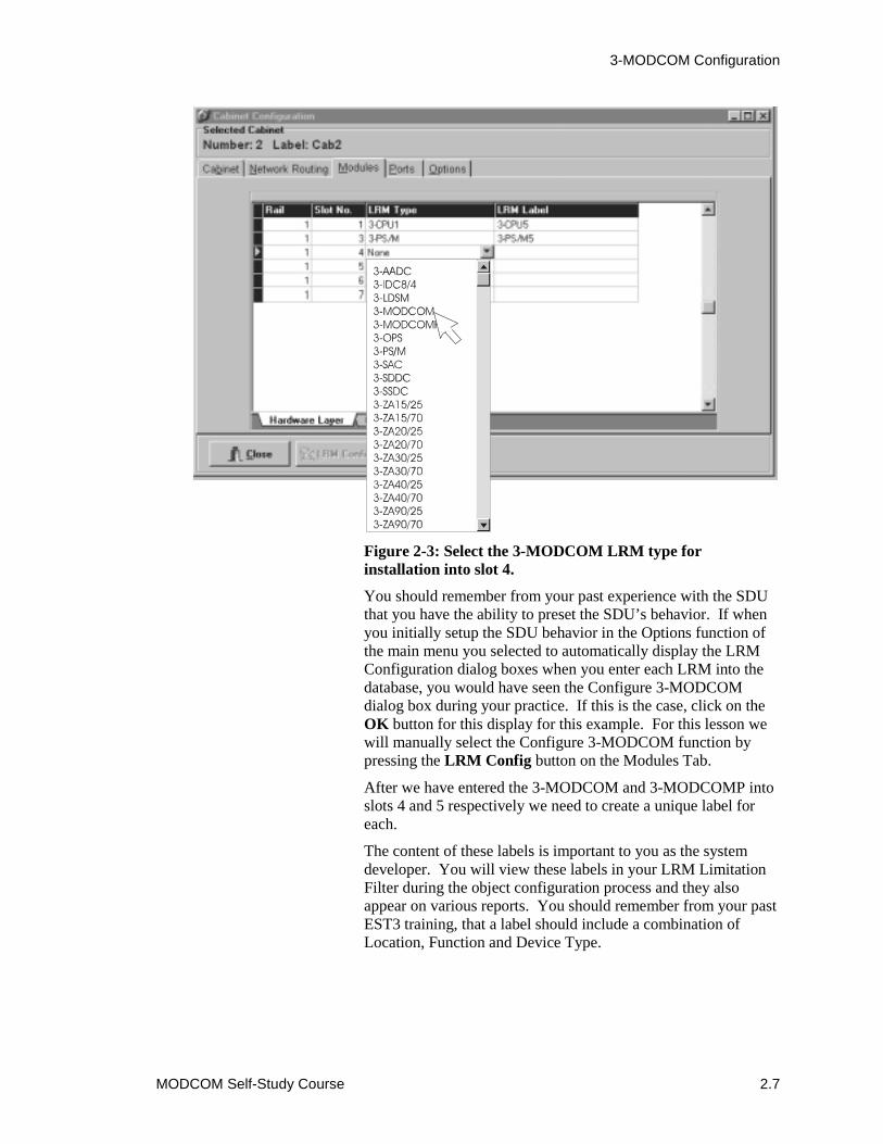
3-MODCOM Configuration
MODCOM Self-Study Course 2.7
Figure 2-3: Select the 3-MODCOM LRM type forinstallation into slot 4.
You should remember from your past experience with the SDUthat you have the ability to preset the SDU’s behavior. If whenyou initially setup the SDU behavior in the Options function ofthe main menu you selected to automatically display the LRMConfiguration dialog boxes when you enter each LRM into thedatabase, you would have seen the Configure 3-MODCOMdialog box during your practice. If this is the case, click on theOK button for this display for this example. For this lesson wewill manually select the Configure 3-MODCOM function bypressing the LRM Config button on the Modules Tab.
After we have entered the 3-MODCOM and 3-MODCOMP intoslots 4 and 5 respectively we need to create a unique label foreach.
The content of these labels is important to you as the systemdeveloper. You will view these labels in your LRM LimitationFilter during the object configuration process and they alsoappear on various reports. You should remember from your pastEST3 training, that a label should include a combination ofLocation, Function and Device Type.

3-MODCOM Configuration
2.8 MODCOM Self-Study Course
In our example of Figure 2-4, Cab2 is the location within our 3-node system. In multi-area, multi-MODCOM facilities, you maywant to include building, floor or other label modifiers to bemore specific.
The example labeling of Figure 2-4 shows that the second labelmodifier gives the function of each MODCOM type. This wouldbe especially important to you in multi-MODCOM applications.In our example, the 3-MODCOM is used for Central MonitoringStation reporting (labeled CMS), while the 3-MODCOMP isused to send event messages to a pager (labeled Pager).
The function label modifier can be important. For example, inMODCOM failover applications, where a backup MODCOM isused, you may want to specify which MODCOM is primary andwhich is the backup. In applications where excessive AccessControl and Keypad Display traffic requires that you dedicate aMODCOM for the Access Control and Keypad Displaycommunications and a separate MODCOM for Central Stationreporting, you may want to specify which MODCOM providesmodem communications and which provides the dialercommunications. The last modifier in our example for bothMODCOMs indicates the device type (labeled Modcom).
Figure 2-4: 3-MODCOM and 3-MODCOMP with labels.
After you have practiced entering the MODCOM into yourproject you are now ready to configure the operating parameters,receivers, and accounts for each MODCOM type.
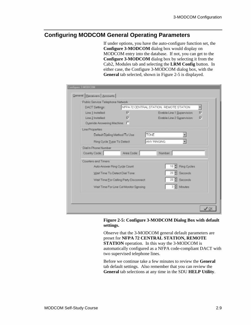
3-MODCOM Configuration
MODCOM Self-Study Course 2.9
Configuring MODCOM General Operating ParametersIf under options, you have the auto-configure function set, theConfigure 3-MODCOM dialog box would display onMODCOM entry into the database. If not, you can get to theConfigure 3-MODCOM dialog box by selecting it from theCab2, Modules tab and selecting the LRM Config button. Ineither case, the Configure 3-MODCOM dialog box, with theGeneral tab selected, shown in Figure 2-5 is displayed.
Figure 2-5: Configure 3-MODCOM Dialog Box with defaultsettings.
Observe that the 3-MODCOM general default parameters arepreset for NFPA 72 CENTRAL STATION, REMOTESTATION operation. In this way the 3-MODCOM isautomatically configured as a NFPA code-compliant DACT withtwo supervised telephone lines.
Before we continue take a few minutes to review the Generaltab default settings. Also remember that you can review theGeneral tab selections at any time in the SDU HELP Utility.

3-MODCOM Configuration
2.10 MODCOM Self-Study Course
To set the DACT ModeAs previously stated the general 3-MODCOM parametersdefault to NFPA 72 CENTRAL STATION, REMOTESTATION DACT compliance. To make your 3-MODCOMfully programmable click on the down-arrow and select FULLYPROGRAMMABLE as shown in Figure 2-6.
Figure 2-6: Selecting DACT settings.
When the FULLY PROGRAMMABLE mode is selected youare allowed to customize the 3-MODCOM operating parameters.This will enable you to configure your MODCOM for AccessControl and Keypad Display modem communications or non-compliant Dialer operations. In that, you can now changeparameters (line parameters, counters and timers) which werelocked to the required default values in the NFPA compliantmode.
CAUTION: Take care when using the fully programmablemode. Check with you local authority before configuring anyvariance from NFPA requirements for Fire and/or Securityapplications.

3-MODCOM Configuration
MODCOM Self-Study Course 2.11
To set the other Public Service Telephone NetworkOptionsAs shown in Figure 2-5, the remaining Public Service TelephoneNetwork setting that may be configured are lines installed andlines supervised for the two 3-MODCOM phone lines and theAnswering Machine Override.
With the NFPA compliance mode selected the two phone linesare required and both must be supervised. These parameters arelocked to the default settings in this mode. Where:
� Line 1or 2 Installed indicates that the correspondingMODCOM phone jack (J20 Line 1 or J21 Line2) isconnected to a switched telephone network.
� Enable Line 1 or 2 Supervision indicates that theMODCOM supervises the Line1 and/or Line 2telephone connections for faults.
Note: When enabled the MODCOM supervision functiondetects <10V during On-hook periods, <10mA during Off-hookperiods and line faults.
In the FULLY PROGRAMMABLE mode you have the abilityto disable or enable line installation and supervision. Use carewhen changing these parameters. Remember that onlyMODCOM line 1 has a ring detection circuit and can acceptincoming calls.
Caution: When the MODCOM is being used in the FULLYPROGRAMMABLE mode as an Access Control and KeypadDisplay communications modem or as a non-compliant (non-fire) single phone line dialer disable Line 2 supervision.
The Override Answering Machine function may be enabled ordisabled in either mode. This is an important feature of AccessControl and Keypad Display communications over a phone linealso connected to an answering machine. This mode enables thecalling computer to seize the line on incoming calls, overridingthe answering machine for Access Control Database (ACDB)and Keypad Display downloads into the EST3 via the system’s3-MODCOM(s).

3-MODCOM Configuration
2.12 MODCOM Self-Study Course
To set Line PropertiesAs shown in Figure 2-5, there are two parameters to select to setline properties:
� Default Dialing Method To Use.
� Ring Cycle Type To Detect.
Figure 2-7 shows the two methods available for the MODCOMsdialing method. The default method is TONE (DTMF) used fortouch tone phone systems. The PULSE method is used forrotary phone systems. The TONE method is faster anduniversally used in the US market. The PULSE method may befound in some international markets. Only use the pulse methodwhen the phone line does not support tone.
Figure 2-7: Default Dialing Method Selections.
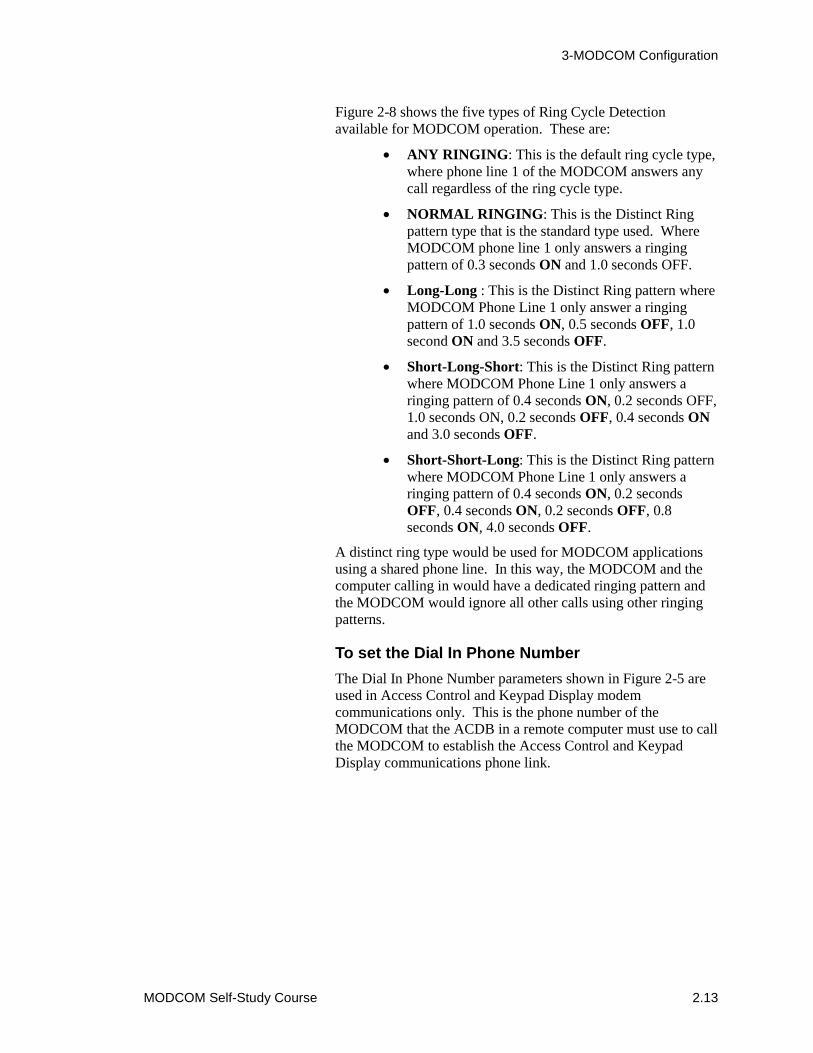
3-MODCOM Configuration
MODCOM Self-Study Course 2.13
Figure 2-8 shows the five types of Ring Cycle Detectionavailable for MODCOM operation. These are:
� ANY RINGING: This is the default ring cycle type,where phone line 1 of the MODCOM answers anycall regardless of the ring cycle type.
� NORMAL RINGING: This is the Distinct Ringpattern type that is the standard type used. WhereMODCOM phone line 1 only answers a ringingpattern of 0.3 seconds ON and 1.0 seconds OFF.
� Long-Long : This is the Distinct Ring pattern whereMODCOM Phone Line 1 only answer a ringingpattern of 1.0 seconds ON, 0.5 seconds OFF, 1.0second ON and 3.5 seconds OFF.
� Short-Long-Short: This is the Distinct Ring patternwhere MODCOM Phone Line 1 only answers aringing pattern of 0.4 seconds ON, 0.2 seconds OFF,1.0 seconds ON, 0.2 seconds OFF, 0.4 seconds ONand 3.0 seconds OFF.
� Short-Short-Long: This is the Distinct Ring patternwhere MODCOM Phone Line 1 only answers aringing pattern of 0.4 seconds ON, 0.2 secondsOFF, 0.4 seconds ON, 0.2 seconds OFF, 0.8seconds ON, 4.0 seconds OFF.
A distinct ring type would be used for MODCOM applicationsusing a shared phone line. In this way, the MODCOM and thecomputer calling in would have a dedicated ringing pattern andthe MODCOM would ignore all other calls using other ringingpatterns.
To set the Dial In Phone NumberThe Dial In Phone Number parameters shown in Figure 2-5 areused in Access Control and Keypad Display modemcommunications only. This is the phone number of theMODCOM that the ACDB in a remote computer must use to callthe MODCOM to establish the Access Control and KeypadDisplay communications phone link.
3-MODCOM Configuration
2.14 MODCOM Self-Study Course
Figure 2-8: Ring Cycle Type Selections.
To set the MODCOM Timers and CountersThe General tab of the Configure 3-MODCOM dialog box(shown in Figure 2-5) provides four configurable counter andtimer parameters:
� Auto-Answer Ring Cycle Count: default value is10 cycles.
� Wait Time To Detect Dial Tone: default value is20 seconds.
� Wait Time For Calling Party Disconnect: defaultvalue is 20 seconds.
� Wait Time For Line Cut Monitor Sensing: defaultvalue is 3 minutes.
The operation aspects of these counter and timer functions aredescribed in Module 1 of this self-study. In most application thedefault values meet the MODCOM communicationrequirements.
Any Ringing
Short-Short-Long
Normal RingLong-LongShort-Long-Short
Any type of ringing
0.4 Secs On, 0.2 Secs Off, 0.4 Secs On, 0.2 Secs Off, 0.8 Secs On, 4.0 Secs Off
0.3 Secs On (minimum), 1.0 Secs Off (minimum)1.0 Secs On, 0.5 Secs Off, 1.0 Secs On, 3.5 Secs Off0.4 Secs On, 0.2 Secs Off, 1.0 Secs On, 0.2 Secs Off, 0.4 Secs On, 3.0 Secs Off
3-MODCOM Configuration
MODCOM Self-Study Course 2.15
The Auto-Answer Ring Cycle Count parameter has a rangefrom 0 to 255 Ring Cycles. This count is the number of ringsthat must occur before the MODCOM goes Off-hook toautomatically answer an incoming call.
When this counter is set to 0 the MODCOM will notautomatically answer calls. In this case calls are manuallyanswered by programming an LED to annunciate an incomingcall and a switch to activate a connection to the phone line.
The Wait Time To Detect Dial Tone parameter is the maximumtime the MODCOM must wait, after going Off-hook, to detect adial tone. This timer has a range from 20 to 255 seconds.Failure to detect a dial tone within the specified time is oneattempt at making a connection. The MODCOM will retry dialtone detection until a preset maximum number of attempts isreached. After the maximum number of attempts is tried atrouble is sent to the EST3 3-CPU1 and displayed on the 3-LCDpanel
The Wait Time For Calling Party Disconnect parameter is thetime the MODCOM must wait before disconnecting an ongoingcall and seizing the phone line. This timer has a range of from 5seconds to 255 seconds. The time to disconnect an ongoing callvaries between TELCO providers in different areas. Generallythis time is from 18 to 90 seconds. You will need to check withyou local TELCO provider to determine the specific timing forCalling Party Disconnect service (if available) in your area.
The Wait Time For Line Cut Monitor Sensing parameter isthe number of minutes the MODCOM must wait beforeannunciating a TELCO line cut. This timer may be set for 1, 2or 3 minutes. UL fire and burglar requirements for this delayvary. You will need to verify the specific timer delay requiredfor you specific application.
Configuring the 3-MODCOM and 3-MODCOMP to this point isthe same. In your practice project it may be useful to configurethe general parameters for both MODCOM types.
Configuring the MODCOM may look like a complex task.However, remember that it has a default configuration, whichmeets the requirements for most MODCOM applications.
A few minutes of research and planning prior to configuring andprogramming your application’s MODCOM(s) can eliminate alot of the time you might spend debugging and reworking yourapplication.
During this configuration process rememberthat Help is only a mouse click away.
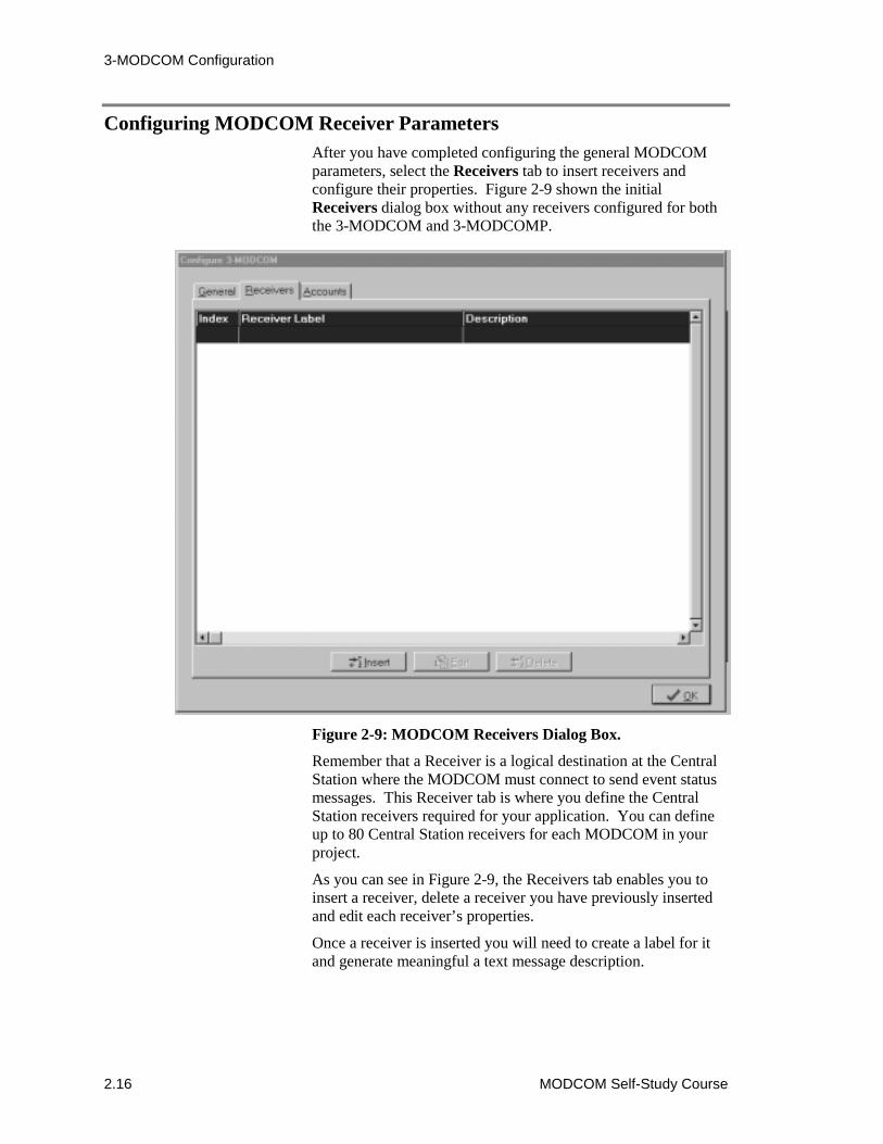
3-MODCOM Configuration
2.16 MODCOM Self-Study Course
Configuring MODCOM Receiver ParametersAfter you have completed configuring the general MODCOMparameters, select the Receivers tab to insert receivers andconfigure their properties. Figure 2-9 shown the initialReceivers dialog box without any receivers configured for boththe 3-MODCOM and 3-MODCOMP.
Figure 2-9: MODCOM Receivers Dialog Box.
Remember that a Receiver is a logical destination at the CentralStation where the MODCOM must connect to send event statusmessages. This Receiver tab is where you define the CentralStation receivers required for your application. You can defineup to 80 Central Station receivers for each MODCOM in yourproject.
As you can see in Figure 2-9, the Receivers tab enables you toinsert a receiver, delete a receiver you have previously insertedand edit each receiver’s properties.
Once a receiver is inserted you will need to create a label for itand generate meaningful a text message description.
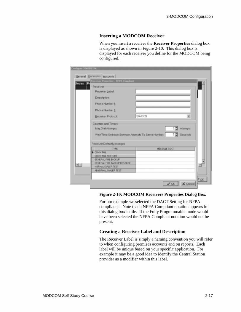
3-MODCOM Configuration
MODCOM Self-Study Course 2.17
Inserting a MODCOM ReceiverWhen you insert a receiver the Receiver Properties dialog boxis displayed as shown in Figure 2-10. This dialog box isdisplayed for each receiver you define for the MODCOM beingconfigured.
Figure 2-10: MODCOM Receivers Properties Dialog Box.
For our example we selected the DACT Setting for NFPAcompliance. Note that a NFPA Compliant notation appears inthis dialog box’s title. If the Fully Programmable mode wouldhave been selected the NFPA Compliant notation would not bepresent.
Creating a Receiver Label and DescriptionThe Receiver Label is simply a naming convention you will referto when configuring premises accounts and on reports. Eachlabel will be unique based on your specific application. Forexample it may be a good idea to identify the Central Stationprovider as a modifier within this label.
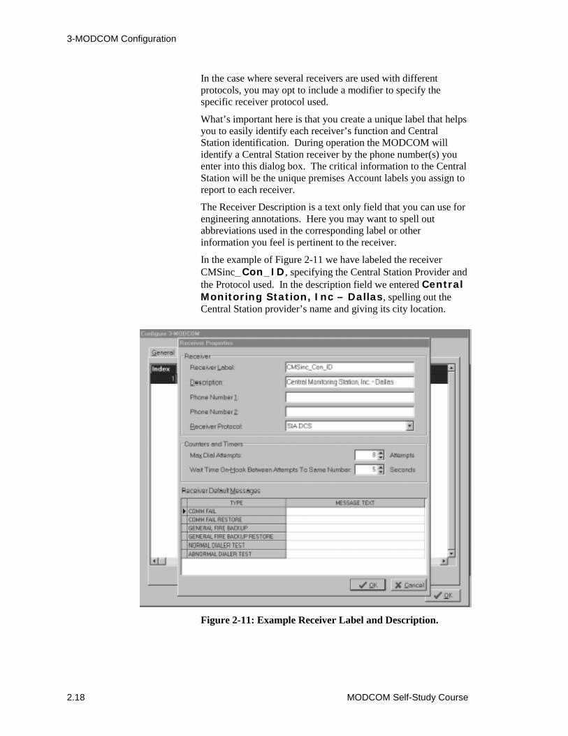
3-MODCOM Configuration
2.18 MODCOM Self-Study Course
In the case where several receivers are used with differentprotocols, you may opt to include a modifier to specify thespecific receiver protocol used.
What’s important here is that you create a unique label that helpsyou to easily identify each receiver’s function and CentralStation identification. During operation the MODCOM willidentify a Central Station receiver by the phone number(s) youenter into this dialog box. The critical information to the CentralStation will be the unique premises Account labels you assign toreport to each receiver.
The Receiver Description is a text only field that you can use forengineering annotations. Here you may want to spell outabbreviations used in the corresponding label or otherinformation you feel is pertinent to the receiver.
In the example of Figure 2-11 we have labeled the receiverCMSinc_Con_ID, specifying the Central Station Provider andthe Protocol used. In the description field we entered CentralMonitoring Station, Inc – Dallas, spelling out theCentral Station provider’s name and giving its city location.
Figure 2-11: Example Receiver Label and Description.

3-MODCOM Configuration
MODCOM Self-Study Course 2.19
Configuring Receiver Phone Numbers and Protocol.The remaining receiver properties to be configured are theprimary and secondary Central Station phone numbers and theprotocol to be used for event reporting.
Phone Number 1 is the Central Station’s primary phone numberdialing string. This is generally the first phone number in thereceiver rotary hunt group for the Central Station. To enable theMODCOM to automatically dial the Central Station receiver,this dialing string must contain all the digits required to call outof the protected premises and connect to the Central Station viathe TELCO lines being used.
This dialing string must include the number being called andmay include:
� Access Codes such as 9 and/or 1 to call out of thepremises and connect to a TELCO phone line.
� Country Codes when they do not require operatorintervention for international calls.
� 3-Digit Area Codes when required for calls to aCentral Station out of the premises area.
� * and # if required in the dialing sequence.
Commas (,) may be included in the dialing string to add a pauseof 6 seconds during the dialing sequence. Hyphens (-), spaces,and left and right brackets ([ and ]) may be used to make thedialing string more visually appealing without affecting thedialing sequence.
Remember that TONE is the default for the dialing mode forMODCOM communications. If you wish to switch to PULSEdialing, simply enter a P to the dialing string. If you wish toreturn to TONE later in the dialing sequence, simply add a T tothe dialing string. You can easily switch between dialingmethods by inserting P and T.
CAUTION: When entering a phone number for a receiverconfigured to use the TAP protocol, use a number from thecarrier’s modem pool not the pool of dial-up touch-tonenumbers.
Phone Number 2 is the Central Station’s secondary phonenumber dialing string. This is generally the second phonenumber in the receiver rotary hunt group for the Central Station.
Note: Using a secondary phone number, which is the secondnumber in a rotary group, overcomes the inability of a rotaryphone system to function, if the primary telephone fails.
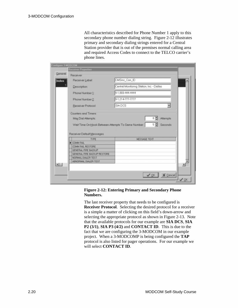
3-MODCOM Configuration
2.20 MODCOM Self-Study Course
All characteristics described for Phone Number 1 apply to thissecondary phone number dialing string. Figure 2-12 illustratesprimary and secondary dialing strings entered for a CentralStation provider that is out of the premises normal calling areaand required Access Codes to connect to the TELCO carrier’sphone lines.
Figure 2-12: Entering Primary and Secondary PhoneNumbers.
The last receiver property that needs to be configured isReceiver Protocol. Selecting the desired protocol for a receiveris a simple a matter of clicking on this field’s down-arrow andselecting the appropriate protocol as shown in Figure 2-13. Notethat the available protocols for our example are SIA DCS, SIAP2 (3/1), SIA P3 (4/2) and CONTACT ID. This is due to thefact that we are configuring the 3-MODCOM in our exampleproject. When a 3-MODCOMP is being configured the TAPprotocol is also listed for pager operations. For our example wewill select CONTACT ID.

3-MODCOM Configuration
MODCOM Self-Study Course 2.21
Figure 2-13: Selecting the Receiver’s Protocol..
To set the Receiver’s Timer and CounterThe Receiver Properties Dialog box provides a configurableMax Dial Attempts counter and a Wait Time On-HookBetween Attempts To Same Number timer.
The Max Dial Attempts counter is set for the maximum numberof times the MODCOM will attempt to contact a specific CentralStation receiver if no handshaking is received on each attempt.The default is 8 attempts. UL limits the number of attemptsallowed to a range from 5 to 10 attempts. Generally, the defaultsetting is sufficient. When the maximum attempts count isreached a trouble pseudo point is sent to the host EST3 system’s3-CPU11 and 3-LCD.
Note: You will need to check with the Central Station and localauthority if a variance is required outside of the recommendedUL requirements.
For our example we will use the default count.

3-MODCOM Configuration
2.22 MODCOM Self-Study Course
The Wait Time On-Hook Between Attempts To SameNumber timer is set for the time the MODCOM must stay On-hook (Wait) between attempts to the same receiver phonenumber. The default for this timer is 5 seconds. The acceptablerange of wait times is from 5 to 120 seconds. Again, the defaulttime is generally sufficient.
Note: This timer value may change when multiple receivers areconfigured for the MODCOM due to varying Central Stationand/or TELCO carrier requirements.
When a second call is made to the same receiver phone number,this time is compared to the Calling Party Disconnect time andthe greater of the two is used as the wait time.
For our example we will use the default time.
To set the Receiver Default Messages.The last of the receiver properties to be configured are theReceiver Default Messages. These messages will vary based onthe protocol selected for communication to the Central Stationreceiver. For our example we will use Contact ID on a Generalreporting basis. Simply enter the appropriate Contact ID code tobe sent to the Central Station for the six types of messages asshown in Figure 2-14.
The Contact ID protocol messages used in our example areexplained in detail in Module 3 of this self-study course. Theactual coded event messages reported to the Central Station canvary greatly based on specific Central Station protocolrequirements and the level of reporting required (general, zonedor point ID). Details for creating the required coded messagesfor the various protocols and applications are given in Module 3and in the SDU’s onboard HELP utility.
As you can see, the MODCOM products are very versatile,enabling you to support an almost unlimited variety of dialerapplications in addition to Access Control and Keypad Displaycommunications. Most MODCOM applications, however, canbe configured in a matter of minutes by taking advantage of thebuilt-in defaults and conventions given in the SDU’s HELPutility.

3-MODCOM Configuration
MODCOM Self-Study Course 2.23
Figure 2-14: Entering Receiver Default Contact ID Messages.
Figure 2-15: 3-MODCOM with two Receivers.

3-MODCOM Configuration
2.24 MODCOM Self-Study Course
Figure 2-16: 3-MODCOMP with one Receiver using TAPProtocol.
For our example project, lets configure two MODCOM receiversfor the Central Monitoring Station, Inc. provider, one for ContactID and the other for SIA DCS protocols as shown in Figure 2-15.Also, lets configure the Pagers R Us MODCOMP for onereceiver using the TAP protocol for a pager application as shownin Figure 2-16.
Before you continue with this lesson to configure the premiseaccounts take this opportunity to practice what you have learnedusing your practice project in the 3-SDU. This lesson steppedyou though the configuration process for the first Central Stationreceiver of the 3-MODCOM. Practice configuring thisMODCOM’s second receiver (Figure 2-15) and the TAPprotocol receiver of the 3-MODCOMP (Figure 2-16).

3-MODCOM Configuration
MODCOM Self-Study Course 2.25
Configuring MODCOM Account PropertiesAfter you have completed configuring the receivers for yourapplication you should establish the premises accounts.Remember that each MODCOM can support up to 255 accountsreporting to up to 80 receivers. This is the point in the processwhere you link each premises account to its correspondingCentral Station receiver and incorporate the relevant user ID oraccount number into the database.
To configure the MODCOM premises accounts select theAccounts tab and observe that the Accounts Tab appearswithout any accounts configured as shown in Figure 2-17.
Figure 2-17: MODCOMP Accounts Dialog Box.
As you can see in Figure 2-17, the Accounts tab enables you toinsert an account, delete an account you have previously insertedor edit an account’s properties.
Once an account is inserted you will need to create a label for itand generate a meaningful text message description.
When you insert an account, the Account Properties dialog boxis displayed as shown in Figure 2-18. This dialog box isdisplayed for each account you define for the MODCOM beingconfigured.
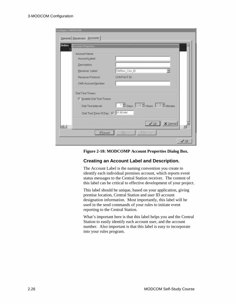
3-MODCOM Configuration
2.26 MODCOM Self-Study Course
Figure 2-18: MODCOMP Account Properties Dialog Box.
Creating an Account Label and Description.The Account Label is the naming convention you create toidentify each individual premises account, which reports eventstatus messages to the Central Station receiver. The content ofthis label can be critical to effective development of your project.
This label should be unique, based on your application, givingpremise location, Central Station and user ID accountdesignation information. Most importantly, this label will beused in the send commands of your rules to initiate eventreporting to the Central Station.
What’s important here is that this label helps you and the CentralStation to easily identify each account user, and the accountnumber. Also important is that this label is easy to incorporateinto your rules program.

3-MODCOM Configuration
MODCOM Self-Study Course 2.27
The Account Description is a text-only field that you use forengineering annotations. Here you may spell out anyabbreviations used in the label. This description will be printedout on the report you send to the Central Station and mustcontain information relevant to Central Station personnel.
In the example of Figure 2-19 we have labeled the AccountCMSinc_CenB_Acc1234, specify the Central Stationprovider, the Customer and the customer account numberprovided by the Central Station. In the description field we haveentered Dallas Central Bank, Account 1234,spelling out the protected premises customer name, customerlocation and relevant account number.
Figure 2-19: Example Account Label and Description.
Selecting the Receiver, its Protocol and enteringthe Central Station Account Number.The next step in configuring an account is to link it to theappropriate Central Station Receiver it is to report to. This issimply done by clicking on the receiver label down-arrow andselecting the appropriate receiver from the previously configuredMODCOM receivers.
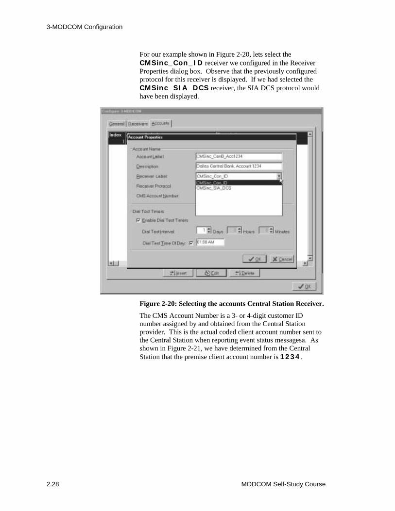
3-MODCOM Configuration
2.28 MODCOM Self-Study Course
For our example shown in Figure 2-20, lets select theCMSinc_Con_ID receiver we configured in the ReceiverProperties dialog box. Observe that the previously configuredprotocol for this receiver is displayed. If we had selected theCMSinc_SIA_DCS receiver, the SIA DCS protocol wouldhave been displayed.
Figure 2-20: Selecting the accounts Central Station Receiver.
The CMS Account Number is a 3- or 4-digit customer IDnumber assigned by and obtained from the Central Stationprovider. This is the actual coded client account number sent tothe Central Station when reporting event status messagesa. Asshown in Figure 2-21, we have determined from the CentralStation that the premise client account number is 1234.

3-MODCOM Configuration
MODCOM Self-Study Course 2.29
Figure 2-21: Entering the Premises Client Account Number.
Setting the Dial Test Timer Properties.If you selected a DACT setting of NFPA 72 Compliant underthe General tab, the timer function is defaulted to Enabled DialTest Timers selected (�), with a Dial Test interval of 1 Day.These properties can not be changed in the NFPA 72 compliantmode. However, the Dial Test Time Of Day timer is selectableand should be set in conjunction with the Central Stationproviders requirements.
When Fully Programmable is selected on the General tab, youcan unpick the Enable Dial Test Timers check box. The fullyprogrammable mode also enables you to change the Dial TestInterval and the Dial Test Time Of Day settings.
CAUTION: Take care when using the fully programmablemode. Check with you local authority before configuring anyvariance from NFPA requirements for Fire and Securityapplications.
The Dial Test Time Of Day, when selected (�), makes the DialTest time specific (01:00 AM shown). When not selected, theDial Test tome is relative, initiating a periodic Dial Test as eachinterval times out. In that, when not selected, any transmissionfrom this account presets the dialer test interval timer to thevalue specified by the Dial Test Interval.
3-MODCOM Configuration
2.30 MODCOM Self-Study Course
Any alarms or troubles that occur during the day do not changethe specified dialer test time.
In Security and Access Control applications, involving openingand closing signals, the Dial Test Time Of Day function shouldnot be selected (relative timing). In this way, the test signaltimer is reset by any off-premises transmission, includingopening and closing signals. This makes the off-premisestransmission act as the test signal, minimizing test traffic to theCentral Station.
CAUTION: Do not select the relative timing test option (timeof day not selected) for fire-only applications. To do so causesthe periodic test signal transmission to occur during the openperiod, disrupting any alarm, trouble or other signal traffic thatmay occur during the day.
In practice, you would continue this process configuring thepremises accounts and linking then to the relevant CentralStation receivers. Take this opportunity to configure additionalaccounts for the three receivers in your practice project.
3-MODCOM Configuration
MODCOM Self-Study Course 2.31
Module 2 evaluation
This concludes Module 2 of the 3-MODCOM Self-Study Course.Return to the objectives stated at the beginning of this module.Study them carefully to ensure that you are comfortable witheach objective. If not, return to that section and review it. Whenyou are satisfied, proceed to Module 3. You will be tested at theend of this self-study course.

3-MODCOM Configuration
2.32 MODCOM Self-Study Course

MODCOM Self-Study Course 3.1
Module 3 MODCOM Communication Protocols
Summary
This self-study module defines each of the 3-MODCOM and 3-MODCOMP protocols used in dialer applications. This moduledescribes and gives examples of the configuration andprogramming procedures required to build and subsequentlytransmit event messages to a Central Station or Paging Service.
ContentIntroduction to module 3 • 3.2Key items • 3.3Objectives • 3.4Supported Message Protocols • 3.5Contact ID Coded Messages • 3.7
MODCOM Loses Communication (Comm) • 3.15MODCOM Loses Communication in the Standalone Mode •3.16Daily Dialer Test • 3.16Coded Contact ID Considerations • 3.17The KISSOFF Tone • 3.17
SIA DCS Coded Messages • 3.18SIA P2 (3/1) and SIA P3 (4/2) Coded Messages • 3.26TAP Protocol Coded Messages (Pager Applications) • 3.28Module 3 evaluation • 3.33

MODCOM Message Protocols
3.2 MODCOM Self-Study Course
Introduction to module 3This module provides a detailed description of the five protocolsused for 3-MODCOM and 3-MODCOMP dialer applications.Also covered are example rules which build and send therequired event messages to a Central Station or Paging Serviceprovider.
This self-study will focus on basic fire-only applications usingthe Contact ID protocol, which is the prevalent fire applicationthat use the MODCOM. Although discussed in this course, themore sophisticated Security, Access Control and Keypad displayMODCOM applications are covered in the factory based EST3Synergy Enabled® Certification Course.
Review the Programming a MODCOM, SIA and Contact IDcodes, SIA substitution strings, TAP substitution strings andProgramming Examples topics in your 3-SDU, Version 3.0Online HELP Utility. You can get the HELP utility throughthe 3-SDU or on your Online Support Tools CD, release 4.0 orlater.
Associated study
Use the following technical reference manuals as associatedstudy material for this module:
• EST3 Installation and Service Manual, (P/N 270380, Rev 4.0 orlater)
• Modem Communicator 3-MODCOM/3-MODCOMP InstallationSheet, (P/N 387476)
MODCOM Message Protocols
MODCOM Self-Study Course 3.3
Key itemsKey points to look for:
• Supported MODCOM protocols• Configuring Event Types and Codes• Building event messages• Using the SEND Command• Using Substitution Strings• Help Utility Templates• CMS Messaging Reports• Receiver Default Messages
Key terms to learn:
• Contact ID protocol• SIA DCS protocol• SIA P2 (3/1) protocol• SIA P3 (4/2) protocol• TAP protocol• Event Qualifier• Event Code• SEND Command• Substitution Strings• KISSOFF Tone
MODCOM Message Protocols
3.4 MODCOM Self-Study Course
ObjectivesUpon completion of this module you will be able to:
1. Describe the parameters, structure and application of theprotocols supported by both MODCOM types.
2. Write rule output statements which build and send the eventmessages to a Central Station and/or a Paging Service.
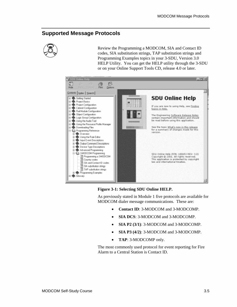
MODCOM Message Protocols
MODCOM Self-Study Course 3.5
Supported Message Protocols
Review the Programming a MODCOM, SIA and Contact IDcodes, SIA substitution strings, TAP substitution strings andProgramming Examples topics in your 3-SDU, Version 3.0HELP Utility. You can get the HELP utility through the 3-SDUor on your Online Support Tools CD, release 4.0 or later.
Figure 3-1: Selecting SDU Online HELP.
As previously stated in Module 1 five protocols are available forMODCOM dialer message communications. These are:
� Contact ID: 3-MODCOM and 3-MODCOMP.
� SIA DCS: 3-MODCOM and 3-MODCOMP.
� SIA P2 (3/1): 3-MODCOM and 3-MODCOMP.
� SIA P3 (4/2): 3-MODCOM and 3-MODCOMP.
� TAP: 3-MODCOMP only.
The most commonly used protocol for event reporting for FireAlarm to a Central Station is Contact ID.
MODCOM Message Protocols
3.6 MODCOM Self-Study Course
This self-study module will focus on Contact ID and fire onlyapplications. Also, most applications will require general eventreporting as defined in Module 1. This lesson also focuses onthese basic applications for the MODCOM. The more advancedSecurity, Access Control and Zone/Point Event Reportingapplications are covered in detail in the factory-based EST3Synergy Enabled® Certification Course.
The protocol established for each Central Station receiverconfigured for a MODCOM is determined by the specificCentral Station provider and customer premises requirements.
Note: The SDU Online HELP utility is a very useful tool touse during the process of configuring and programming aMODCOM. Not only does this utility give descriptions of theprocesses, it also provides a template of the standard EST3protocol coded messages and example MODCOM rules.Remember that you can copy information from the HELPutility, paste it into your SDU rules editor and edit it to fit yourapplication. By using the default MODCOM properties and theHELP utility in this way, most MODCOM applications can beconfigured and programmed in a matter of minutes.
The actual configuration and programming for MODCOMapplications can vary greatly depending on the type of premisesapplication (fire only to fully integrated), each specific CentralStation’s protocol requirements, TELCO services provided andother premises requirements. It would be unrealistic to attemptto cover every variation a MODCOM application may have inthis self-study course. This course will focus on basisapplications and techniques you would use to develop yourspecific application.
In this module we will discuss the various message protocolssupported by the MODCOM dialer for event message reportingto a Central Station.
MODCOM Message Protocols
MODCOM Self-Study Course 3.7
Contact ID Coded MessagesContact ID is the most frequent protocol used by CentralStations for fire applications. The entire message in thisprotocol is composed of hexadecimal coded messages. ContactID utilizes the modified hexadecimal conventions required bythe TELCO carriers shown in Figure 1-10 of Module 1.
This modified hexadecimal coded message can contain:
� User Account Number
� Event Qualifier
� Event Code
� Partition(for Access Control and SecurityApplications) or Zone ID Code
� Point, device or object ID Code.
� User ID for Security/Access applications.
To better understand the Contact ID protocol lets breakdown theinformation sent to the Central Station in this coded message.The 16-digit Contact ID format used for EST3 MODCOMapplications is:
ACCTMTQEEEGGPPPSWhere:
� ACCT is the hexadecimal 3- or 4-digit user accountnumber. This account code is included in themessage sent to the Central Station by including theaccount label in the SEND command statement usedto initiate the communications to the CentralStation. This account label is created during theconfiguration process.
For example: SEND ‘Account_Label’
� MT is a hexadecimal 2-digit message type codeautomatically sent by the MODCOM to the CentralStation specifying the protocol used. For ContactID this code is 18.
� Q is a 1-digit event qualifier code that specifies thetype of event being reported. Where:
� 1 is a new event activation or an opening.
� 3 is a new event restoration or a closing.
� 6 is a previously reported event condition(Status) which is still present.
MODCOM Message Protocols
3.8 MODCOM Self-Study Course
� EEE is a 3-digit event code that specifies the actualevent that is being reported. Such as, a Fire Alarm(110), a supervisory (210), a trouble (310), etc.
� GG is a 2-digit group number code that specifieswhich predefined partition or group the eventoccurred in. Using 00 indicates that no group isbeing specified. Up to 255 groups may be identifiedby this 2-digit hexadecimal code.
� PPP is a 3-digit point ID code that specifies theactual point, device or object that is being reported.Using 000 indicates that no specific point is beingreported. Up to 3,375 points may be identified bythis 3-digit hexadecimal code.
� S is a 1-digit checksum code automatically sent bythe MODCOM to the Central Station to verifycommunications.
A single substitution string may be used in Contact ID toincorporate the User ID into this message. In this case, themessage field in the output command would be“QEEEGG$(USER)”. Where the USER ID code is sent inthe 3-digit point ID field (PPP).
Note: In some Security and Access Control applications thismay be a 20-digit format where the user ID may be included.
In either case, the User ID is created in the Access ControlDatabase and is the pin number for individuals initiating events,such as gaining access to the protected premises.
CAUTION: All activation event coded messages must have arestoral message. In fire applications all new event activationmessages sent must also send a restoral message before theprotected premise is considered to be in a normal state.
Figure 3-2 shows an example of creating the coded Contact IDmessage for a fire alarm. In this example we have previouslyconfigured the system for event reporting on a point basis. Wehave configured an account label (Account_Label) andentered a CMS account number of 1234.
In our example device 15 of zone 1 went into alarm. Device 15could be a smoke detector, a heat detector, a manual pull stationor a waterflow switch. We have already configured the accountnumber to be sent to the Central Station. The message type(MT) is automatically sent by the MODCOM, which is an 18for our Contact ID example.
MODCOM Message Protocols
MODCOM Self-Study Course 3.9
Since this is an initial activation, the event qualifier is 1. Thenfrom the template in the HELP Utility we have determined thatthe event code for a fire alarm is 110. Since we haveconfigured our system into logical groups the group code for thealarm point is 01. Point 15 in this group went active makingthe device code for this alarm point 015. The checksum forthis message is calculated (1) and automatically sent by theMODCOM.
Figure 3-2: Contact ID Coded Message Example.
You must write a rule to report this event to the Central Station.This example shows the Output Statement that must be includedin the rule to send the appropriate hexadecimal coded message.The SEND command is used to initiate this communication tothe Central Station.
You include the Account label within single quotation marks(‘Acount_Label’) in this output statement. Thisautomatically sends the 3- or 4-digit CMS account number(1234) as the first 4 digits of the coded message. TheMODCOM automatically sends the message type (18) based onthe protocol type you configured for the Central Station receiver.
Account 1234 is reporting a Fire Alarm for device 15 of zone 1 Where 1234, 15 and 1 are hexidecimal integers.
Contact ID format breakdown for this example
AccountNumber
MessageType
EventQualifier
EventCode
GroupCode
DeviceCode
Checksum
ACCT MT Q EEE GG PPP S
1234 18 1 110 01 015 1
You would write the following output command in your rule toinitiate this event’s communications to the Central Station .
SEND ‘Account_Label’ MSG “111001015”;
1234181110010151
Actual Code sent to Central StationWhere the and codes are automatically generated by the MODCOM.MT S
MODCOM Message Protocols
3.10 MODCOM Self-Study Course
The remainder of the coded message you are responsible formust be included in this output statement as the message. To dothis you would enter MSG into your output statement followedfor the remainder of the message enclosed in double quotationmarks (“QEEEGGPPP”), which sends the next part of thecoded message (111001015). The last integer sent is thechecksum (1), which is automatically sent by the MODCOM.
Note: A Numerical or Hexadecimal Operator (<N> or <H>)could be used in the message field to calculate the GGPPPvalue to be sent.
The event code of this message contains valuable informationfor the Central Station. In MODCOM dialer applications abroad variety of events of different types may be reported to theCentral Station.
Figure 3-3 defines the structure of the 3-digit event code part ofthe message sent to the Central Station. The first integer of theevent code is the event classification shown in the order ofreporting priority. Where 1 is alarm, 2 is supervisory, 3 istrouble, and so on.
The 2-digit event type gives the type of event being reported.For example, the event type would be 10 for fire and 30 forburglary. It should be easy to see that the 3-digit event code fora fire alarm would be 110 and the event code for a burglaralarm would be 130.
If the event being reported is an initial activation, the 3-digitevent codes are proceeded by a 1 (1110 for fire and 1130for burglary, respectively). A restoration event must be sent foreach activation previously reported. In this case, the event codeis proceeded by a 3 (3110 and 3130, respectively).
The last digit of the event code enables you to specify morespecific event information to the Central Station. For example, aperimeter burglar alarm is 31, an interior burglar alarm is 32,an outdoor Burglar Alarm is 36, and so on.

MODCOM Message Protocols
MODCOM Self-Study Course 3.11
Figure 3-3: Event Code Definitions.
Figure 3-4 shows a small sample of the event codes used forEST3 applications for fire and burglar alarms. As you can see,if you wished to report a general fire alarm you would use anevent code of 110. To report the more specific smoke firealarm event you would use 111, and so on.
EEEEvent CodeEvent Classification
Event Type
EventClassifications
ALARMS1xx
SUPERVISORY2xx
TROUBLES3xx
OPEN/CLOSED(Access Control)
4xx
BYPASS/DISABLE5xx
TEST & MISC.6xx
EventType xx
Where is the custom 2-digitevent code for:
xx Medical, Fire, Panic,
Burglary, General or 24 Hour
Where is the custom 2-digitevent code for:
xx Fire Supervisory,
Water Presure, Gatevalve, Tamperor Pump Activated
Where is the custom 2-digitevent code for:
xx System Trouble,
Ground Fault, LRM Trouble, Communication, Battery or Detector
Where is the custom 2-digitevent code for:
xx Open/Close,
Arm/Disarm, Access Granted orCancel
Where is the custom 2-digitevent code for:
xx System, Sounder,
Notification, Communicationor Relay
Where is the custom 2-digitevent code for:
xx Test, Log or
Schedule
Priority
Highest
Lowest
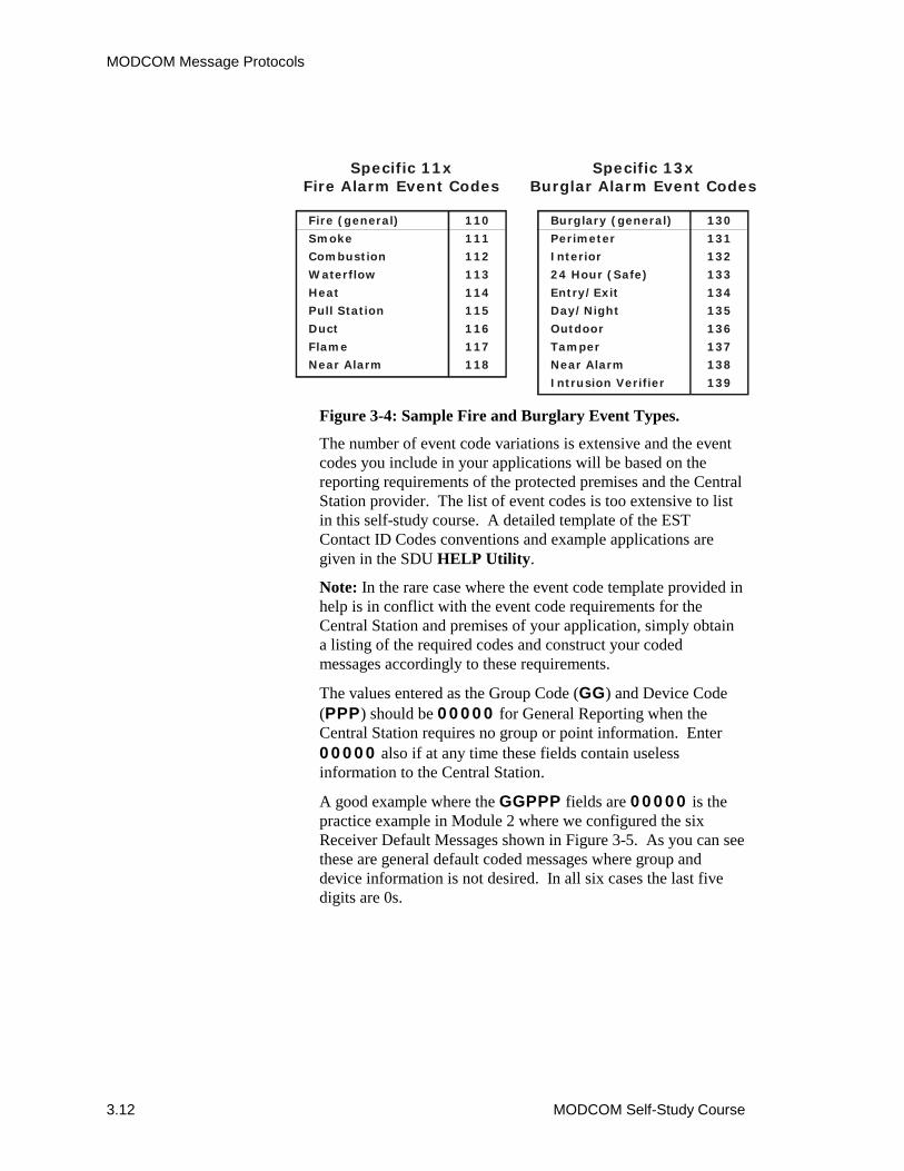
MODCOM Message Protocols
3.12 MODCOM Self-Study Course
Figure 3-4: Sample Fire and Burglary Event Types.
The number of event code variations is extensive and the eventcodes you include in your applications will be based on thereporting requirements of the protected premises and the CentralStation provider. The list of event codes is too extensive to listin this self-study course. A detailed template of the ESTContact ID Codes conventions and example applications aregiven in the SDU HELP Utility.
Note: In the rare case where the event code template provided inhelp is in conflict with the event code requirements for theCentral Station and premises of your application, simply obtaina listing of the required codes and construct your codedmessages accordingly to these requirements.
The values entered as the Group Code (GG) and Device Code(PPP) should be 00000 for General Reporting when theCentral Station requires no group or point information. Enter00000 also if at any time these fields contain uselessinformation to the Central Station.
A good example where the GGPPP fields are 00000 is thepractice example in Module 2 where we configured the sixReceiver Default Messages shown in Figure 3-5. As you can seethese are general default coded messages where group anddevice information is not desired. In all six cases the last fivedigits are 0s.
Fire (general)
Smoke
Combustion
Waterflow
Heat
Pull Station
Duct
Flame
Near Alarm
110
111
112
113
114
115
116
117
118
Specific 11xFire Alarm Event Codes
Burglary (general)
Perimeter
Interior
24 Hour (Safe)
Entry/Exit
Day/Night
Outdoor
Tamper
Near Alarm
Intrusion Verifier
130
131
132
133
134
135
136
137
138
139
Specific 13xBurglar Alarm Event Codes

MODCOM Message Protocols
MODCOM Self-Study Course 3.13
Figure 3-5: Default Contact ID coded messages with 0s inGGPPP fields.
The SDU provides a report utility that is accessible from itsMain Menu bar. This report utility gives you the ability to printa CMS Messaging Report on an account-by-account basis.After you have completed the configuration process for theMODCOM and have established its receiver protocol messages,you should print these reports and send them to the CentralStation for verification.
To print these reports, select Reports from the Main Menu andCMS Messaging Reports from the pull-down menu as shown inFigure 3-6.

MODCOM Message Protocols
3.14 MODCOM Self-Study Course
Figure 3-6: Selecting the CMS Messaging Report.
Observe that the CMS Report Criteria dialog box appears asshown in Figure 3-7. This dialog box enables you to select thedesired report by specifying the cabinet, the MODCOM, thereceiver and the specific account. Once your selections aremade, simply click OK to view and print the desired report.
Figure 3-7: Selecting CMS Report Criteria.
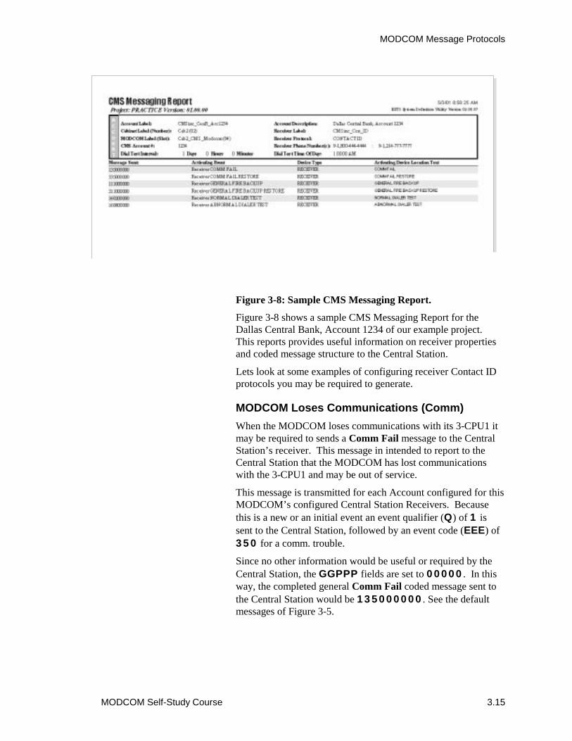
MODCOM Message Protocols
MODCOM Self-Study Course 3.15
Figure 3-8: Sample CMS Messaging Report.
Figure 3-8 shows a sample CMS Messaging Report for theDallas Central Bank, Account 1234 of our example project.This reports provides useful information on receiver propertiesand coded message structure to the Central Station.
Lets look at some examples of configuring receiver Contact IDprotocols you may be required to generate.
MODCOM Loses Communications (Comm)When the MODCOM loses communications with its 3-CPU1 itmay be required to sends a Comm Fail message to the CentralStation’s receiver. This message in intended to report to theCentral Station that the MODCOM has lost communicationswith the 3-CPU1 and may be out of service.
This message is transmitted for each Account configured for thisMODCOM’s configured Central Station Receivers. Becausethis is a new or an initial event an event qualifier (Q) of 1 issent to the Central Station, followed by an event code (EEE) of350 for a comm. trouble.
Since no other information would be useful or required by theCentral Station, the GGPPP fields are set to 00000. In thisway, the completed general Comm Fail coded message sent tothe Central Station would be 135000000. See the defaultmessages of Figure 3-5.

MODCOM Message Protocols
3.16 MODCOM Self-Study Course
When MODCOM communications is restored with its 3-CPU1,it sends a Comm Fail restore message to the Central Stationsreceiver. This restoral message notifies the Central Station thatthe MODCOM has re-established communications with theCPU. Because this is a restoral event an event qualifier of 3 issent to the Central Station followed by the same event code of350. Again the GGPPP field is all 0s and the completedComm Fail restored message sent to the Central Station is335000000. See the default message of Figure 3-5.
MODCOM Loses Communications in theStandalone Mode.The standalone mode is an emergency backup operation for theEST3 system when the 3-CPU1 or its communications fails. Ifthe MODCOM loses communications with its 3-CPU1 when thecommon alarm standalone mode is active, it sends a GeneralFire Backup alarm message to the Central Station’s receiver.
Because this is a new or an initial event, an event qualifier of 1is sent to the Central Station, followed by an event code of 110for a fire alarm. In the Standalone mode a general fire alarm isactivated and no group or point ID information is available. Dueto this the GGPPP field is all 0s and the completed GeneralFire Backup alarm message sent to the Central Station is111000000, as shown in the default message of Figure 3-5.
When the general fire alarm standalone event is restored aGeneral Fire Backup alarm restoral message is sent to thereceiver. Using what you have learned, it should be obvious thatthe completed message sent to the Central Station is311000000, as shown in the default message of Figure 3-5.
Daily Dialer TestWhen configured, the daily dialer test event, when the system isin a normal state, sends an event code of 602, proceeded by anevent qualifier of 1. Again, the GGPPP field is all 0s and thecomplete message sent to the Central Station is 160200000,as shown in the default message of Figure 3-5.
The daily dialer test event, when the system is in an abnormalstate, sends an event code of 608, proceeded by an eventqualifier of 1, making the complete message sent160800000, as shown in the default message of Figure 3-5.

MODCOM Message Protocols
MODCOM Self-Study Course 3.17
Coded Contact ID Message ConsiderationsWhen creating information regarding events which occur on acustomer’s premises that are sent to a Central Station provideryou need to consider:
� The information should be in a form and containcontent that is easily interpreted by the CentralStation operators.
� Use the same or standardized event messages for allprojects, which have a common Central Stationprovider.
� Put Group or Point ID numbers in an order that ismeaningful and easily interpreted by the CentralStation operator.
� As much as practically possible, minimize eventmessage transaction time to limit the amount of timethe line is seized and not available to the customer.
� When programming the MODCOM event reportingparameters do not send unnecessary repeat eventmessages or multiple messages. For example, if youreported an event on a point ID basis to the CentralStation, you should not also send a general eventmessage for the same event.
The KISSOFF ToneThe Central Station Receiver sends a KISSOFF tone to theMODCOM indicating that the coded event message has beensuccessfully received. If the MODCOM does not detect aKISSOFF tone it redials and resends the message until aKISSOFF tone is received or the preset maximum number ofattempts is reached.

MODCOM Message Protocols
3.18 MODCOM Self-Study Course
SIA DCS Coded MessagesThe SIA DCS protocol is composed of alphanumeric ASCII textcharacters. This protocol offers greater flexibility in the codedmessage structure than Contact ID and is frequently used inapplications incorporating Security and Access Controlmonitoring. SIA DCS coded messages can simply be 2-integeralphanumeric event coded messages or messages with this eventcode and detailed location information.
The 3-SDU also provides a message building tool called aSubstitution String for constructing SIA DCS coded eventmessages to be sent to the Central Station. This programmingfeature enables you to incorporate time, date and userinformation into the coded event message.
CAUTION: Due to the flexibility of SIA DCS messagestructures it’s is critical that you become familiar with themessaging requirements that the Central Station provides for theprotected premises application you are developing.
The SIA DCS coded message can contain:
� User account number
� Event code
� Date
� Time
� User ID
� Partition
� Area, zone and and/or device ID
To better understand the SIA DCS protocol let’s break down thecoded message sent to the Central Station. First we need torealize that in SIA DCS, these messages are sent to the CentralStation in Data Code Packets and Modifier Code Packets thatmake up a Data Block.
As in the case of Contact ID the Data Block must include a useraccount number (ACCT). This account code is included in themessage sent to the Central Station by including the accountlabel, created during the configuration process, in the SENDCommand statement used to initiate the communications to theCentral Station (e.g. SEND ‘Acount_Label’).

MODCOM Message Protocols
MODCOM Self-Study Course 3.19
The format for the SIA DCS Data Code Pack is:
TTAAAA*
Where:
� TT is the 2-digit, capital ASCII character letters thatrepresent the event code (Data Code Type). Forexample, FA is the event code or type for a fire alarmand BA is the event code or type for a burglar alarm.
Note: a complete listing of the 2-interger SIA DCSevent codes is provided in the SDU HELP Utility.
� AAAA is the 4-digit address number. This is anoptional field. To send a general fire alarm you wouldsimply send FA. However, for group or point reportingyou would enter the group or point code here. This fieldmust contain an ASCII representation of a hexadecimalnumber. However, you can enter decimal orhexadecimal addresses. If your project conventions arein decimal you can report up to 9999 separate pointevents. By using hexadecimal conventions orconverting decimal to hexadecimal, you can report up toFFFF events (equivalent to 65,516 decimal).
Note: This field does not require leading 0s.
The 2-digit Event Code (Data Code Type) is the only codedmessage required for SIA DCS event reporting, other than theaccount number. The other fields are added as the eventreporting requirements get more detailed.
Other information may be included in the Data Block sent to theCentral Station by adding optional Modifier Code Packets. TheSDU enables you to insert modifier code packets by using theSubstitution String described in Module 1. There are three typesof modifier packets used for MODCOM SIA DCS applications:
� The DATE may be reported with the event bysending the daMM-DD-YY modifier code packet,where da is the type code. This is accomplished inthe SDU rule by incorporating the substitution string$(DATE) in the message field of the SENDcommand output statement that sends the DataBlock to the Central Station.

MODCOM Message Protocols
3.20 MODCOM Self-Study Course
� The TIME may be reported with the event bysending the tiHH:MM:SS modifier code packet.Where ti is the type code. This is accomplished inthe SDU rule by incorporating the substitution string$(TIME) in the message field of the SENDcommand output statement that sends the DataBlock to the Central Station.
� The subscriber (user) ID may be reported with theevent by sending the idSSSS modifier codepacket. Where id is the type code. This isaccomplished in the SDU rule by incorporating thesubstitution string $(USER) or $(USERID) inthe message field of the SEND command outputstatement that sends the Data Block to the CentralStation. $(USER) simply sends a 4-digit usercode while $(USERID) sends the user code withthe id prefix. This could be a critical field inSecurity and Access Control application whereindividual pin numbers may be required (e.g. afterhours entry into protected premise).
Note: As in the case of Contact ID, all activation SIA DCSevent coded messages should have a restoral message. In fireapplications all new event activation messages sent must alsosend a restoral message before the protected premises isconsidered to be in a normal state.
The order that the Data Code and Modifier Code packets aresent in the Data Block is not important, other than the ModifierCode packets must proceed the Data Code packet. It may benecessary to check with the Central Station provider for thedesired structure of these messages.
Figure 3-9 shows an example of creating the SIA DCS codedmessage for an Access Granted event, which sends the Date,Time, the Door entered and the individual who gained access.We have previously created the Account Label and entered theCMS Account Number of 1234.
From the template in our HELP Utility we have determined thatthe SIA DCS event code for Access Granted is DG (all uppercase). In this example we want to include the door beingaccessed as a decimal number in the address field. In our rulewe will use a numerical operator of <N> to calculate the avalue of 0015 from the rule’s input statement.

MODCOM Message Protocols
MODCOM Self-Study Course 3.21
Figure 3-9: SIA DCS Coded Message Example for AccessGranted Event.
In some applications the user codes are used in place of theEvent Codes address field. For example, in Access Controlapplications an extended closing time (CE) would incorporatethe user code in the AAAA field. In this case the outputcommands message may be written:
“$(DATE)$(TIME)CE$(USER)”
Now the user code follows the Event Code without the lowercase id.
Account 1234 is reporting Access Granted on May 17, 2001 at 8:30 AMat Premise Door 15 to the individual whose pin number is 0337.
Data Code Packet FormatBreakdown for this example
AccountNumber
EventCode
Address<N> or <H>
ACCT TT AAAA
1234 DG 0015
You would write the following output command in your rule toinitiate this event’s communications to the Central Station .
SEND ‘Account_Label’ MSG “$(DATE)$(TIME) DG<N>”;$(USER)
1234da05-17-01ti08:30:00 DG0015 id0337
Actual Data BlockCode sent to Central Station
Modifier Code Packet FormatBreakdown for this example
SubstitutionString
TypeCode
DateFormat
$(DATE) da MM-DD-YY
da 05-17-01
DATE
SubstitutionString
TypeCode
DateFormat
$(TIME) ti HH:MM:SS
ti 08:30:00
TIME
SubstitutionString
TypeCode
DateFormat
$(USERID) id SSSS
id 0337
USER
DG is the Event Codeor data type code for anAccess Granted event.
The code type for Data Codepackets are always upper-case.
The code type for Modifier Codepackets are always lower-case.
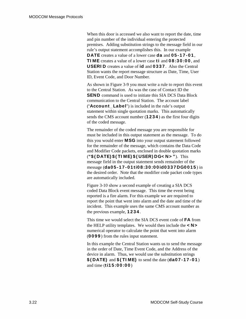
MODCOM Message Protocols
3.22 MODCOM Self-Study Course
When this door is accessed we also want to report the date, timeand pin number of the individual entering the protectedpremises. Adding substitution strings to the message field in ourrule’s output statement accomplishes this. In our exampleDATE creates a value of a lower case da and 05-17-01,TIME creates a value of a lower case ti and 08:30:00, andUSERID creates a value of id and 0337. Also the CentralStation wants the report message structure as Date, Time, UserID, Event Code, and Door Number.
As shown in Figure 3-9 you must write a rule to report this eventto the Central Station. As was the case of Contact ID theSEND command is used to initiate this SIA DCS Data Blockcommunication to the Central Station. The account label(‘Account_Label’) is included in the rule’s outputstatement within single quotation marks. This automaticallysends the CMS account number (1234) as the first four digitsof the coded message.
The remainder of the coded message you are responsible formust be included in this output statement as the message. To dothis you would enter MSG into your output statement followedfor the remainder of the message, which contains the Data Codeand Modifier Code packets, enclosed in double quotation marks(“$(DATE)$(TIME)$(USER)DG<N>”). Thismessage field in the output statement sends remainder of themessage (da05-17-01ti08:30:00id0337DG0015) inthe desired order. Note that the modifier code packet code typesare automatically included.
Figure 3-10 show a second example of creating a SIA DCScoded Data Block event message. This time the event beingreported is a fire alarm. For this example we are required toreport the point that went into alarm and the date and time of theincident. This example uses the same CMS account number asthe previous example, 1234.
This time we would select the SIA DCS event code of FA fromthe HELP utility templates. We would then include the <N>numerical operator to calculate the point that went into alarm(0099) from the rules input statement.
In this example the Central Station wants us to send the messagein the order of Date, Time Event Code, and the Address of thedevice in alarm. Thus, we would use the substitution strings$(DATE) and $(TIME) to send the date (da07-17-01)and time (ti15:00:00)
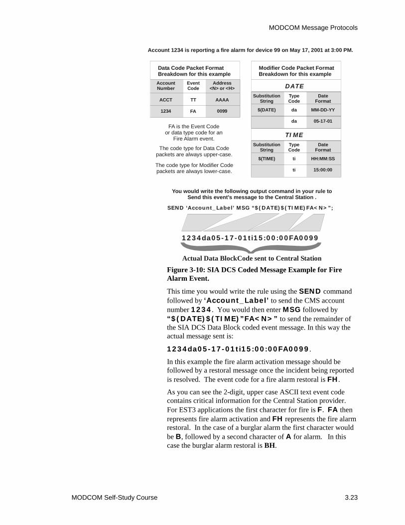
MODCOM Message Protocols
MODCOM Self-Study Course 3.23
Figure 3-10: SIA DCS Coded Message Example for FireAlarm Event.
This time you would write the rule using the SEND commandfollowed by ‘Account_Label’ to send the CMS accountnumber 1234. You would then enter MSG followed by“$(DATE)$(TIME)”FA<N>” to send the remainder ofthe SIA DCS Data Block coded event message. In this way theactual message sent is:
1234da05-17-01ti15:00:00FA0099.
In this example the fire alarm activation message should befollowed by a restoral message once the incident being reportedis resolved. The event code for a fire alarm restoral is FH.
As you can see the 2-digit, upper case ASCII text event codecontains critical information for the Central Station provider.For EST3 applications the first character for fire is F. FA thenrepresents fire alarm activation and FH represents the fire alarmrestoral. In the case of a burglar alarm the first character wouldbe B, followed by a second character of A for alarm. In thiscase the burglar alarm restoral is BH.
Account 1234 is reporting a fire alarm for device 99 on May 17, 2001 at 3:00 PM.
Data Code Packet FormatBreakdown for this example
AccountNumber
EventCode
Address<N> or <H>
ACCT TT AAAA
1234 FA 0099
You would write the following output command in your rule toSend this event’s message to the Central Station .
SEND ‘Account_Label’ MSG “ FA<N>”; $(DATE)$(TIME)
1234 FA0099 da05-17-01ti15:00:00
Actual Data BlockCode sent to Central Station
Modifier Code Packet FormatBreakdown for this example
SubstitutionString
TypeCode
DateFormat
$(DATE) da MM-DD-YY
da 05-17-01
DATE
SubstitutionString
TypeCode
DateFormat
$(TIME) ti HH:MM:SS
ti 15:00:00
TIMEFA is the Event Code
or data type code for anFire Alarm event.
The code type for Data Codepackets are always upper-case.
The code type for Modifier Codepackets are always lower-case.

MODCOM Message Protocols
3.24 MODCOM Self-Study Course
The list of event codes is too extensive to list in this self-studycourse. A detailed template of the EST SIA DCS event codeconventions and example applications are given in the SDUOnline HELP Utility. Figure 3-11 gives some example eventcode conventions used for fire and burglar applications.
Figure 3-11: Sample Fire and Burglary SIA DCS EventCode Types.
The SIA DCS protocol configured MODCOM has six defaultmessages, which may be configured as shown in Figure 3-12.You may want to take this opportunity to configure the SIA DCSreceiver in your practice project in this way.
Remember that you also have the capability of printing a CMSMessaging Report, which you can send to the Central Station.Figure 3-13 shows a sample CMS Messaging Report for SIADCS protocol.
Fire Alarm
Fire Alarm Restore
Fire Alarm Cross Point
Fire Bypass
Fire Test
Fire Cancel
Fire Supervisory
FA
FH
FM
FB
FX
FC
FS
SIA DCSFire Event Codes
Burglary Alarm
Burglar Alarm Restore
Burglar Alarm Cross Point
Burglar Bypass
Burglar Test
Burglar Cancel
Burglar Supervisory
BA
131
BM
BB
BX
BC
BS
SIA DCSBurglar Event Codes
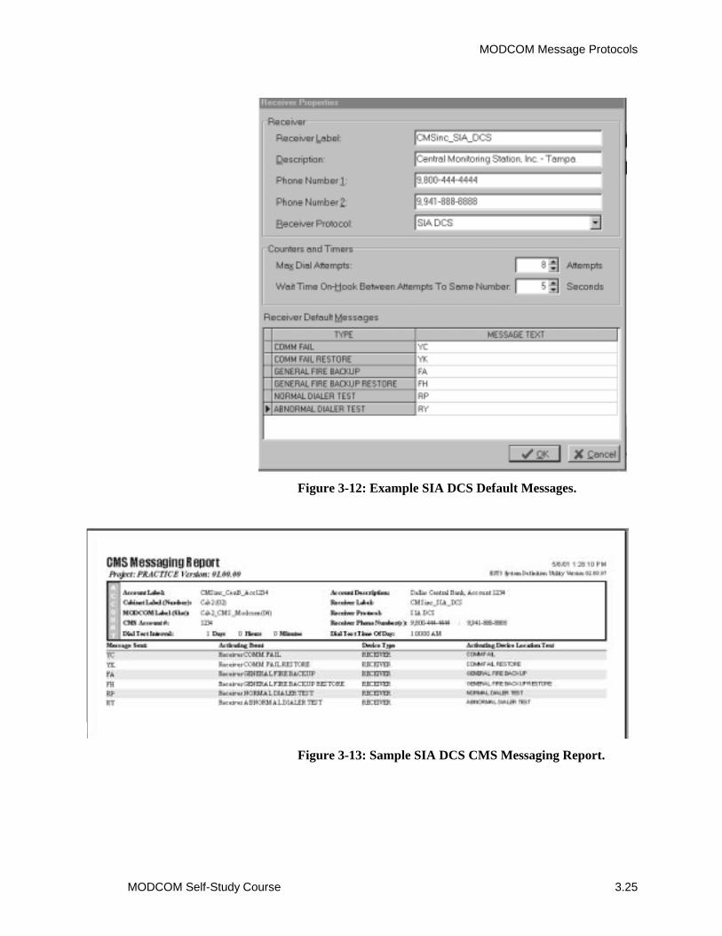
MODCOM Message Protocols
MODCOM Self-Study Course 3.25
Figure 3-12: Example SIA DCS Default Messages.
Figure 3-13: Sample SIA DCS CMS Messaging Report.

MODCOM Message Protocols
3.26 MODCOM Self-Study Course
SIA P2 (3/1) and SIA P3 (4/2) Coded Messages
SIA P2 (3/1) and SIA P3 (4/2) protocols offer the simplestmethods of event reporting to the Central Station. Where:
SIA P2 (3/1) consists of a short, predefined hexadecimalmessage, which contains a 3-digit account number and a1-digit event code.
SIA P3 (4/2) consists of a short, predefined hexadecimalmessage, which contains a 4-digit account number and a2-digit event code. SIA P2 also can use the $(USER)substitution string to send a used ID number. In thiscase the first digit of the event code is 0 and the outputstatement message would be:
“0$(USER)”
In both cases, you would simply configure the MODCOM forthe desired protocol, create an account label and enter the CMSaccount number. Next, you would establish the event codeconventions for your project. You may want to consult theCentral Station provider to establish these conventions.However, in most cases, you would simply define each requiredevent type and print a CMS Messaging Report of your customevent messages to be sent to the Central Station provider.
The SIA P2 (3/1) protocol provides the capability to define from1 to F (15) events, while the SIA P3 (4/2) provides the capabilityto define from 01 to FF (225 decimal) events.
The actual event code is up to you. For example, using SIA P2(3/1), 1 may be a fire alarm, 2 may be a fire alarm restoration, 3may be a burglar alarm, and so on. In this example, the outputstatements to send a fire alarm and it’s restoral for account 123might be:
SEND ‘Account_Label’ MSG “1” which sends1231 to the Central Station for the initial fire alarm.
SEND ‘Account_Label’ MSG “2” which sends1232 to the Central Station for the restoration of theinitial fire alarm event.
If we were using the 2-digit SIA P3 (4/2) protocol, 10 may bethe fire alarm, 11 may be the fire alarm restoral, 12 might be thefire pump failure, and so on. In this case, burglary might be the2x range of codes. In that, 20 is the burglar alarm, 21 is theburglar alarm restoral, and so on. In this example, the outputstatements to send a fire alarm event and it’s restoral for account1234 might be:
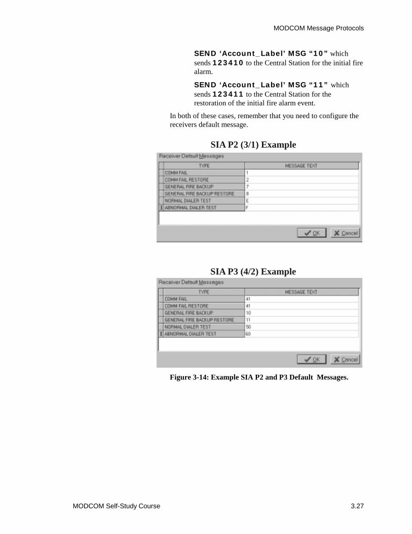
MODCOM Message Protocols
MODCOM Self-Study Course 3.27
SEND ‘Account_Label’ MSG “10” whichsends 123410 to the Central Station for the initial firealarm.
SEND ‘Account_Label’ MSG “11” whichsends 123411 to the Central Station for therestoration of the initial fire alarm event.
In both of these cases, remember that you need to configure thereceivers default message.
Figure 3-14: Example SIA P2 and P3 Default Messages.
SIA P2 (3/1) Example
SIA P3 (4/2) Example

MODCOM Message Protocols
3.28 MODCOM Self-Study Course
TAP Protocol Coded Messages (Pager Applications)The TAP protocol is used with the 3-MODCOMP for pagerapplications. The TAP protocol consists of predefined ASCIItext messages of up to 59 characters (including spaces) fordisplay on a pager. The TAP message format generally consistsof a 4- or 7-digit pager ID number and a custom configurablemessage, separated by a carriage return ($(CR)). Someapplications may use up to 10 digits or more. Remember thatthe more characters you use for the Pager ID, the less areavailable for the message.
The SDU provides a great deal of flexibility in developing theTAP messages. Substitution Strings are also used in the TAPprotocol to develop the ASCII text message to be sent to thepager service. The TAP message can contain:
� Pager ID: Generally 4 to 7 digits or characters.
� ASCII Message: Generally defines the event (e.g.Fire, Burglary, Emergency, etc.)
� Date: Inserts an 8- to 10-character date (includingdashes) into the 59-character message by using oneof the four DATE substitution strings with thefollowing syntax:
$(DATE) enters MMDDYY
$(MMDDYYYY)
$(DDMMYY)
$(DDMMYYYY)
� Time: Inserts an 8- or 10-character time (includingcolons and A or P) into the 59-character message byusing one of the two TIME substitution strings withthe following syntax:
$(TIME): enters HH:MM:SS in 24-hourclock format
$(TIME12): enters HH:MM:SS A or P in 12hour clock format
� User: Inserts a 4-character user identification code(e.g. individual pin number) into the 59-charactermessage by using the $(USER) substitution string.

MODCOM Message Protocols
MODCOM Self-Study Course 3.29
� Location: Inserts up to 42 characters from a EST3point’s message field into the 59 character message,based on available unused character positions. Thissubstitution string also lets you specify a range ofcharacter positions from this EST3 message field tobe included into the pager message. The syntaxwould be:
$(LOCATION): enters the entire 42-character EST3 point message.
$(LOCATION:M-N): enters the specificEST3 point message characters specified by thecharacter range M-N.
Another consideration you must make when constructing thesepager messages is the use of spaces for readability. Rememberthat a space is a character position within this pager message.
Since you have a maximum of 59 characters available for pagermessages, its should be obvious to you that preplanning messagecontent may be critical.
In the example of Figure 3-15 we have configured our pagermessage for a 7-digit pager ID code, a 10-digit date($(MMDDYYYY)) a 10-digit time ($(TIME12)), a 21-digit ASCII location text field ($(LOCATION:1-21)), plusappropriate spaces for readability. As you can see we have 8unused digits available for additional information.
Let’s say we wanted to add an ASCII text event message field ofFIRE ALARM to this pager message. This 10-digit field doesnot fit. One solution might be to use FIRE or FA. Anothersolution might be that during planning we changed the Pager IDto a 4-digit field, changed the date to a 8-digit field($(MMDDYY)), and changed the time to the 24-hour clock($(TIME)). Now we have 15 unused digits and the FIREALARM event message easily fits.
Another consideration during the planning phase might be theactual display format of the pagers used in your application. InPager Display Example 1 of Figure 3-15 the message displayedis that which was configured for our earlier example without anevent message. The pager we are using has 20-character linesfor display. As you can see the message line breaks withinfields affecting the readability of the message.
If during the configuration process, we added a second spaceafter the date and changed to the 24-hour clock format, themessage line breaks at appropriate places and the display iseasily read, as shown in Pager Display Example 2.

MODCOM Message Protocols
3.30 MODCOM Self-Study Course
Figure 3-15: TAP Protocol Pager Message Considerations.
Example 1Pager Display
59 Character Pager Message Field
1234567 05-18-2001 01:11:20 P FLOOR4 PULL EAST EXIT
1234567 05-18-2001 13:11:20 FLOOR4 PULLEAST EXIT
Example 2Pager Display
MODCOM Message Protocols
MODCOM Self-Study Course 3.31
The location substitution string provides a great deal offlexibility when building pager messages. For example, theobject that is initiating an event has a SDU object message of:
Elevator Lobby SMK Level 2 Parking Area
Using $(LOCATION) in your output statement would sendall 39 characters of the object message as part of the TAPprotocol message for display on the pager.
If you only wished to send Level 2 Parking as part of thepager message you would use $(LOCATION:19-34).
Figure 3-16 shows an example of creating a TAP protocol pagermessage for a fire alarm event. In this example we are requiredto report a fire alarm event to the PageSmart pager serviceprovider indicating the ID number, the device, its location, andthe time and date of the incident.
We have preconfigured each alarm device’s object message sothat the required device and location information is in characterpositions 9 through 21. We will use a 7-digit Pager ID number,the MMDDYY date format and the 24-hour clock time format.
As in the case of the other protocols we need to write a ruleusing the SEND command, followed by the account label tosend the event message to the pager service provider. This timethe account label (PageSmart) simply dials up the pagerservice phone number and an account number is not sent as partof the message. You would then enter MSG followed by:
“1234567$(CR)$(DATE) $(TIME) Fire Alarm$(LOCATIOM:9_21)”
This is the pager event message to be displayed. The first 7digits direct this message to the appropriate pager. The carriagereturn ($(CR)) substitution string indicates that the eventmessage follows. The message field within the output statementthen sends the actual message for display:
1234567 05-17-01 20:30:00
Fire Alarm Room 202 Smoke
The use of wildcards and N or H indexing (variables) ispermitted in creating TAP protocol messages. Theseprogramming features enable you calculate message numericalvariables from the input statement, making writing rules aproductive effort.

MODCOM Message Protocols
3.32 MODCOM Self-Study Course
Figure 3-16: TAP Protocol Pager Message Example for afire alarm.
Remember that if a restoration message is required a separaterestoral output command must be written. In this example ofFigure 3-16 this might look like:
1234567 05-17-01 22:15:00
Restored Room 202 Smoke
Note: Remember that it is critical that you check with thepaging service provider to insure that they accept TAP protocoland for any message length limitations.
Pager ID Number
1234567
You would write the following output command in your rule toinitiate this event’s communications to the pager service .
SEND ‘PageSmart’ MSG “1234567$(CR)$(DATE) $(TIME) Fire Alarm $(LOCATION:9-21)”;
1234567 05-17-01 20:30:00 Fire Alarm Room 202 Smoke
Actual pager message sent to the pager service for display.
SubstitutionString
DateFormat
$(DATE) MM-DD-YY
05-17-01
DATE
SubstitutionString
TimeFormat
$(TIME) HH:MM:SS
20:30:00
TIME
SubstitutionString
LocationText
$(LOCATION:9-21) Room 202 Smoke
LOCATION
Where the Pager ID numberis always followed by a
carriage return to separate it from the actual pager message.
Each alarm device’s object message field (location) has been configuredso that character positions 9 through 21 contain the required location
information for the pager message. The object message for this smoke detector is .“Floor 2 Room202 Smoke”
PagerID$(CR)
The PageSmart account is reporting a Smoke Alarm on May 17, 2001 at 8:30 PM, which was activated by the Room 202 Smoke Detector.
MODCOM Message Protocols
MODCOM Self-Study Course 3.33
Module 3 evaluationThis concludes Module 3 of the 3-MODCOM Self-Study Course.Return to the objectives stated at the beginning of this module.Study them carefully to ensure you are comfortable with eachobjective. If not, return to that section and review it. When youare satisfied, please continue on to Module 4. You will be testedat the end of this self-study course.

MODCOM Message Protocols
3.34 MODCOM Self-Study Course

MODCOM Self-Study Course 4.1
Module 4 Programming MODCOM Applications
Summary
This module gives the recommended rules for reporting FireAlarm, Fire Supervisory, Common Trouble and System LowBattery Trouble events in fire alarm system general reportingapplications to the Central Station. The module shows theconstruction and defines the purpose of each rule.
ContentIntroduction to module 4 • 4.2Key items • 4.3Objectives • 4.4General Fire Alarm MODCOM Dialer Applications • 4.5
Pre-programming Considerations • 4.5General Fire Alarm Event Reporting Requirements • 4.6Recommended General Fire Alarm System Event ReportingRules • 4.8 Common Fire Alarm • 4.8 Common Fire Supervisory • 4.10 Common Trouble • 4.11 System Low Battery Trouble • 4.12
Module evaluation • 4.16
Programming MODCOM Applications
4.2 MODCOM Self-Study Course
Introduction to module 4This module describes writing rules to support general reportingto a Central Station of Fire Alarm events using Contact IDprotocol. This module lists pre-programming considerations,states requirements and gives recommended MODCOM SENDcommand rules for general fire alarm event reporting.
This self-study will focus on basic fire only applications usingthe Contact ID protocol, which is the prevalent fire applicationin which the MODCOM used. Although discussed in thiscourse, the more sophisticated Security, Access Control andKeypad display MODCOM applications are covered in thefactory-based EST3 Synergy Enabled® Certification Course.
Review the Programming a MODCOM, Contact ID codes andProgramming Examples topics in your 3-SDU, Version 3.0HELP Utility. You can get to the HELP utility through theSDU or from your Online Support Tools CD, release 4.0 or later.

Programming MODCOM Applications
MODCOM Self-Study Course 4.3
Key items
Key points to look for:
• Pre-programming considerations for MODCOM dialerapplications.
• NFPA 72 Central Station, Remote Station requirements.• Recommended General Fire Alarm Event Messaging.• Using the SEND Command with command qualifiers.• Using System Events (FirstAlarm, First Supervisory and
First Trouble) in general event reporting rules.
Key terms to learn:
• SEND Command• System Event• Command Qualifier• Common Alarm• Common Supervisory• Common CMS Trouble• System Event

Programming MODCOM Applications
4.4 MODCOM Self-Study Course
Objectives
Upon completion of this module you will be able to:
1. Write rules to support General Fire Alarm event reportingvia the 3-MODCOM.
2. Describe the purpose and use of the SEND Command.
3. Describe the purpose and use of command qualifiers.
4. Create Contact ID coded event messages for General FireAlarm applications.
Programming MODCOM Applications
MODCOM Self-Study Course 4.5
General Fire Alarm MODCOM Dialer ApplicationReview the Programming a MODCOM, Contact ID codes andProgramming Examples topics in your 3-SDU, Version 3.0HELP Utility. You can get the HELP utility through the SDUor from your Online Support Tools CD, release 4.0 or later.
Review the Programming the MODCOM section in Module 1 ofthis self-study before you continue with this module’s lesson.
During this lesson it may be helpful to use the practice projectyou started in Module 2 to practices programming aspects forthis general fire alarm reporting MODCOM dialer application.
This module will focus on basic general fire alarm MODCOMdialer event reporting applications only and the Contact IDprotocol. The more sophisticated security, access control andkeypad display MODCOM dialer and modem applications arecovered in the factory-based EST3 Synergy Enabled®
Certification Course.
Pre-Programming ConsiderationsIt is important to remember that the MODCOM has predefineddefault parameters set for NFPA 72 Central Station, RemoteStation fire applications. When developing a general fire alarmevent reporting dialer application these defaults preconfiguremost of the MODCOM properties required for this application.
Also remember that the HELP Utility provides protocoltemplates and example rules which are a resource during theconfiguration and programming tasks. It is a simple matter tocopy a rule from Help, paste it into your rules editor and thenedit the rule’s object labels to fit your specific project.
What you will need to configure for general fire alarm eventreporting dialer application is:
1. Insert the required Central Station receivers.
2. Label each Central Station receiver.
3. Create a description for each Central StationReceiver.
4. Enter the primary and secondary Central Stationphone number for each receiver being configured.
5. Select Contact ID protocol.
6. Create the Contact ID coded default hexadecimalmessages.
7. Insert the required premises accounts.
8. Label each premise account.
Programming MODCOM Applications
4.6 MODCOM Self-Study Course
9. Create a description for each premises account.
Note: This description is printed on the CMSMessaging Report you send to the Central Station. It’scontent should be meaningful to and address therequirements of the Central Station provider.
10. Enter the CMS Account Number to be sent to theCentral Station, which identifies the premisesaccount reporting an event.
11. Select which of the configured Central Stationreceivers this account is to report to.
Detailed instructions for the MODCOM configuration processare given in Module 2 of this self-study and in the SDU HELPUtility.
General Fire Alarm Event Reporting RequirementsFor fire alarm event reporting to a Central Station using ContactID, any alarm point (e.g. Smoke Detector, Pull Station,Waterflow, etc.) that goes into alarm sends a hexadecimal codedgeneral fire alarm event message to the Central Station. Whenthe incident causing the fire alarm is resolved and all alarmpoints are restored, a hexadecimal coded restore message is sentto the Central Station.
In a general fire alarm system any point which has a tamper (e.g.a sprinkler system gatevalve) is a supervisory point. If asupervisory event effect the Life-Safety Fire Alarm System theCentral Station considers it to be a fire supervisory event. In ourgeneral fire alarm event reporting application any firesupervisory point that goes active sends a hexadecimal codedgeneral fire supervisory event message to the Central Station.When the incident causing the fire supervisory event is resolvedand all supervisory points are restored, a hexadecimal codedrestore message is sent to the Central Station.
When any point in the fire alarm system goes into trouble ahexadecimal coded general trouble event message is sent to theCentral Station. Again, when the incident causing the troubleevent is resolved and all trouble points are restored, ahexadecimal coded restore message is sent to the CentralStation.
As required by NFPA 72, the Central Station should receive aDial Test report every 24 hours from the protected premises.This report enables the Central Station to periodically (24-hourdefault) determine that the monitored system is working duringnormal non-event periods.
Programming MODCOM Applications
MODCOM Self-Study Course 4.7
This 24-hour default Dial Test is preconfigured when you selectthe default NFPA 72 Central Station, Remote Stationapplication and does not require a custom rule.
In general fire alarm event reporting applications an AC PowerFailure is sent to the Central Station as a general troublemessage on a 6 to 12 hour delayed basis. During this loss of ACpower period, its backup batteries power the system. In thisway, if an alarm event occurs during this AC power loss period ageneral fire alarm event message is still sent to the CentralStation.
The Central Station needs to monitor the integrity of thesebatteries during an AC power loss period. When these batteriesstart to weaken, loosing their ability to support the fire alarmsystem, a unique trouble event message should be sent to theCentral Station. This message should be sent to the CentralStation before the battery backup completely fails, reporting thatthe premises may become unprotected.
Within the EST3 3-CPU1 microcode a BATT_TRBL_CC_SSlocal trouble type pseudo point is automatically generated whenbattery capacity drops below acceptable levels. Where CC isthe battery’s host cabinet address and SS is the slot location ofthe cabinet’s 3-PSMON LRM that monitors battery status.
For example, if the backup batteries in cabinet 03 start to die, theBATT_TRBL_03_03 pseudo point goes active. We can usethis local trouble type, low battery pseudo point label within arule’s input statement to send a unique low battery trouble eventto the Central Station. In single cabinet standalone applicationsthis input statement would be:
LOCALTROUBLE ‘BATT_TRBL_*’ :
Where the wildcard (*) includes all batteries in the cabinet.
Note: If the periodic test message was not received at thepredefined time it would be safe to assume that the systembatteries are dead.
Multinode network applications use an AND group to reportbattery trouble events and are described later in this lesson.Based on these general fire alarm event reporting applicationrequirements, we need to write rules to send eight general andContact ID event messages to the Central Station. In all eightcases, the event messages are general in nature and do notrequire additional group or point information. Due to this factwe will enter 00000 into the GGPPP Contact ID fields.
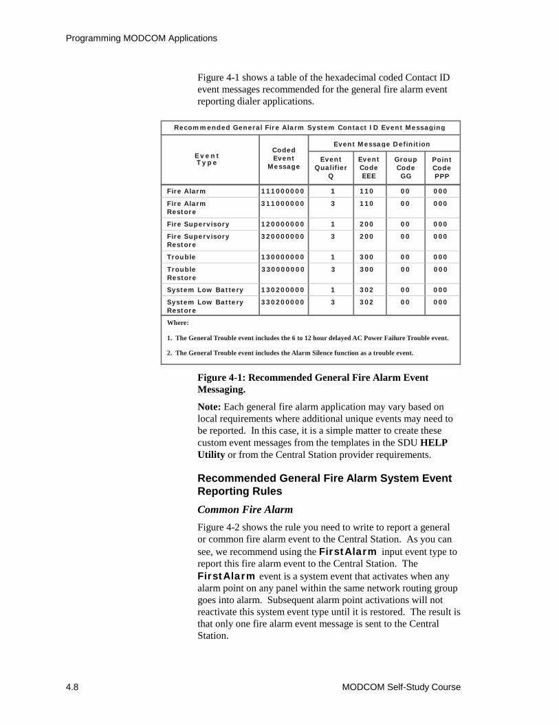
Programming MODCOM Applications
4.8 MODCOM Self-Study Course
Figure 4-1 shows a table of the hexadecimal coded Contact IDevent messages recommended for the general fire alarm eventreporting dialer applications.
Figure 4-1: Recommended General Fire Alarm EventMessaging.
Note: Each general fire alarm application may vary based onlocal requirements where additional unique events may need tobe reported. In this case, it is a simple matter to create thesecustom event messages from the templates in the SDU HELPUtility or from the Central Station provider requirements.
Recommended General Fire Alarm System EventReporting RulesCommon Fire AlarmFigure 4-2 shows the rule you need to write to report a generalor common fire alarm event to the Central Station. As you cansee, we recommend using the FirstAlarm input event type toreport this fire alarm event to the Central Station. TheFirstAlarm event is a system event that activates when anyalarm point on any panel within the same network routing groupgoes into alarm. Subsequent alarm point activations will notreactivate this system event type until it is restored. The result isthat only one fire alarm event message is sent to the CentralStation.
EventType
CodedEvent
Message
Event Message Definition
EventQualifier
Q
EventCodeEEE
GroupCodeGG
PointCodePPP
Recommended General Fire Alarm System Contact ID Event Messaging
Fire Alarm
Fire Supervisory
Fire SupervisoryRestore
Trouble
TroubleRestore
System Low Battery
System Low BatteryRestore
111000000
Fire AlarmRestore
311000000
120000000
320000000
130000000
330000000
130200000
330200000
1
3
1
3
1
3
1
3
110
110
200
200
300
300
302
302
00
00
00
00
00
00
00
00
000
000
000
000
000
000
000
000
Where:
1. The General Trouble event includes the 6 to 12 hour delayed AC Power Failure Trouble event.
2. The General Trouble event includes the Alarm Silence function as a trouble event.
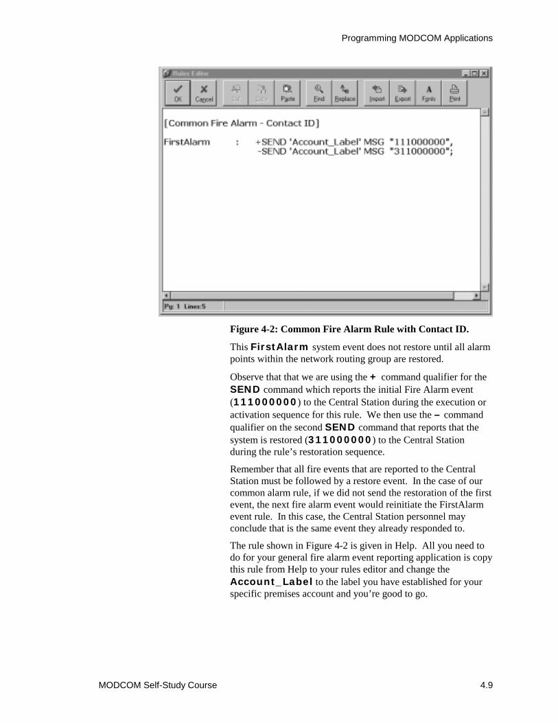
Programming MODCOM Applications
MODCOM Self-Study Course 4.9
Figure 4-2: Common Fire Alarm Rule with Contact ID.
This FirstAlarm system event does not restore until all alarmpoints within the network routing group are restored.
Observe that that we are using the + command qualifier for theSEND command which reports the initial Fire Alarm event(111000000) to the Central Station during the execution oractivation sequence for this rule. We then use the – commandqualifier on the second SEND command that reports that thesystem is restored (311000000) to the Central Stationduring the rule’s restoration sequence.
Remember that all fire events that are reported to the CentralStation must be followed by a restore event. In the case of ourcommon alarm rule, if we did not send the restoration of the firstevent, the next fire alarm event would reinitiate the FirstAlarmevent rule. In this case, the Central Station personnel mayconclude that is the same event they already responded to.
The rule shown in Figure 4-2 is given in Help. All you need todo for your general fire alarm event reporting application is copythis rule from Help to your rules editor and change theAccount_Label to the label you have established for yourspecific premises account and you’re good to go.
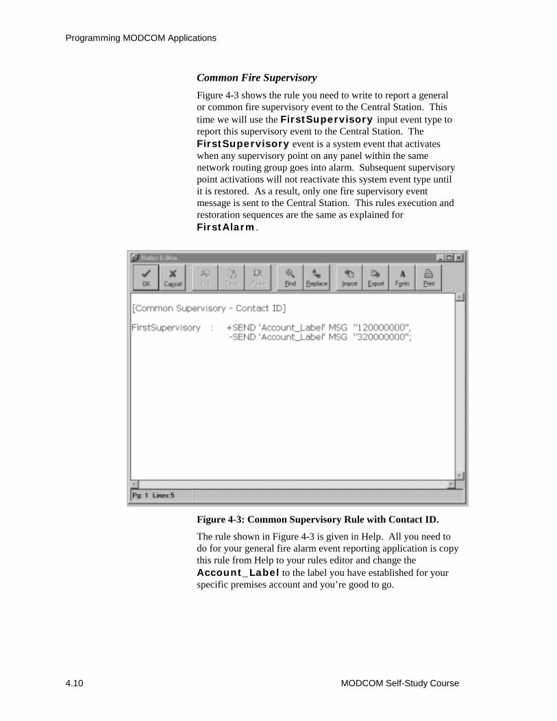
Programming MODCOM Applications
4.10 MODCOM Self-Study Course
Common Fire SupervisoryFigure 4-3 shows the rule you need to write to report a generalor common fire supervisory event to the Central Station. Thistime we will use the FirstSupervisory input event type toreport this supervisory event to the Central Station. TheFirstSupervisory event is a system event that activateswhen any supervisory point on any panel within the samenetwork routing group goes into alarm. Subsequent supervisorypoint activations will not reactivate this system event type untilit is restored. As a result, only one fire supervisory eventmessage is sent to the Central Station. This rules execution andrestoration sequences are the same as explained forFirstAlarm.
Figure 4-3: Common Supervisory Rule with Contact ID.
The rule shown in Figure 4-3 is given in Help. All you need todo for your general fire alarm event reporting application is copythis rule from Help to your rules editor and change theAccount_Label to the label you have established for yourspecific premises account and you’re good to go.
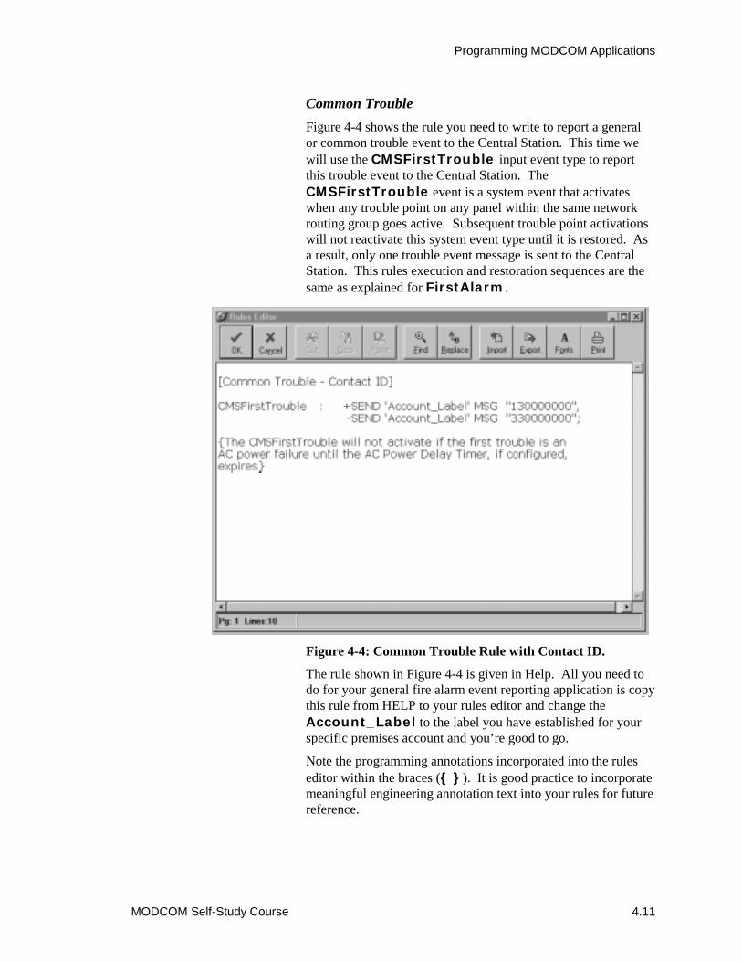
Programming MODCOM Applications
MODCOM Self-Study Course 4.11
Common TroubleFigure 4-4 shows the rule you need to write to report a generalor common trouble event to the Central Station. This time wewill use the CMSFirstTrouble input event type to reportthis trouble event to the Central Station. TheCMSFirstTrouble event is a system event that activateswhen any trouble point on any panel within the same networkrouting group goes active. Subsequent trouble point activationswill not reactivate this system event type until it is restored. Asa result, only one trouble event message is sent to the CentralStation. This rules execution and restoration sequences are thesame as explained for FirstAlarm.
Figure 4-4: Common Trouble Rule with Contact ID.
The rule shown in Figure 4-4 is given in Help. All you need todo for your general fire alarm event reporting application is copythis rule from HELP to your rules editor and change theAccount_Label to the label you have established for yourspecific premises account and you’re good to go.
Note the programming annotations incorporated into the ruleseditor within the braces ({ }). It is good practice to incorporatemeaningful engineering annotation text into your rules for futurereference.

Programming MODCOM Applications
4.12 MODCOM Self-Study Course
System Low Battery TroubleFigure 4-5 shows the rule you need to write to report a lowsystem battery, local trouble event to the Central Station for a\standalone system (single cabinet). We will use theLocalTrouble input event type to report this low systembattery event and its subsequent restoration to the CentralStation. This rule’s execution and restoration sequences are thesame as explained for FirstAlarm.
Figure 4-5: System Low Battery Trouble Rule with ContactID.
The rule shown in Figure 4-5 is given in Help. All you need todo for your general fire alarm event reporting application is copythis rule from Help to your rules editor and change theAccount_Label to the label you have established for yourspecific premises account and you’re good to go.
Observe that the LocalTrouble event type is not a systemevent and requires the label of the specific pseudo point youwish to use to activate this rules execution (in this caseBATT_TRBL_*).
Programming MODCOM Applications
MODCOM Self-Study Course 4.13
In multinode EST3 applications and when BPS supplies areused, this rule can send multiple system battery low troublemessages to the Central Station without restoration messages.To eliminate multiple battery trouble message reporting, allBATT_TRBL_CC_SS pseudo point must be configured into anAND group (such as, Low_Battery_Group) with anactivation of 1. This AND group’s activation is used to executethe rule which reports to the Central Station. In this case theinput statement would be:
LocalTrouble ‘Low_Battery_Group’ :
In more advanced fire alarm event reporting applications youmay choose to initiate general event reporting from the rules thatalso initiate complex NAC responses and/or audio egressmessages. In this case you can simply add the output statementsfrom our general rule examples to these NAC response rules andachieve the desired event reporting. However, in this casealways remember that each alarm activation event messagerequires a restoration message.
The more advanced zone, point ID, security and access controlevent reporting applications are beyond the scope of this self-study course. Advanced dialer applications are covered in thefactory-based EST3 Synergy Enabled® Certification Course.
This concludes the 3-MODCOM Self-Study course.
Before you proceed to the online test as indicated in the Module4 Evaluation, it may be a good idea to review this course.
A review crossword puzzle has been provided on the next pageas a fun way to review the MODCOM.

Programming MODCOM Applications
4.14 MODCOM Self-Study Course
DOWN ACROSS1. DACT setting which makes the MODCOM non-NFPA 72 custom configurable. (two words)2. A ________ detection circuit is used to determine phone line loss during ON-Hook periods.6. Default Dialing Method.7. The MODCOM determines that it has achieved connection with the Central Station by detecting the ______ ______. (two words)
The logical destination at the Central Station (CMS) where the MODCOM must connect to and subsequently send event status to.9. Enables you to execute an output command only on a rule's activation or restoration sequence. (two words)10. Simplest method of event reporting to a CMS.14. MODCOMs may be configured as backups to one another to support __________ __________ operation. (two words)17. Naming convention for premise accounts used to identify the account within the rule.20. Up to ____ MODCOM's may be installed within a networked EST3 system.21. Hexadecimal coded event reporting communications protocol which is most common to Fire Alarm system applications.
8.
24. Sent by the Central Station to indicate that the message has been successfully received.
3. Modem Communicator module which supports TAP protocol.4. The unique circuit in MODCOM phone line 1 to answer incoming calls (two words)5. A ________ detection circuit is used to determine phone line loss during OFF-Hook periods.7. The MODCOM function which enables it to provide CMS monitoring communications via the phone lines.11. To enter the 3-MODCOM or 3-MODCOMP into your application database you must select Configure, Cabinets and the _______ tab.12. Event classification which uses 1xx event codes in the hexadecimal Contact ID messages.13. Preferred telephone service option that prevents incoming calls from jamming MODCOM dialer operations. (three words)15. A valuable tool to use during the MODCOM configuration and programming process.16. Output command that is used to send the event message to the Central Station.18. The TAP protocol messages are composed of _______ text characters.19. Identifies the user site sending an event to the Central Station.22. An input object you configure so that when activated from a rule, it executes a predefined sequence of output commands. (two words)23. Telelocator Alphanumeric Protocol.25. The MODCOM function which enables it to download Access Control and Keypad Display data into the integrated EST3 system via the phone lines.26. Programming feature that enables you to customize SIA DCS and TAP protocol event message fields. (two words)27. The Substitution String which enables you to incorporate part or all of the object message into the TAP protocol message.
Review Crossword Puzzle

Programming MODCOM Applications
MODCOM Self-Study Course 4.15
1
2
3
4
5 6
7 8
9 10 11
12
13 14
15 16
17
18 19 20
21
22
23 24
25
26 27
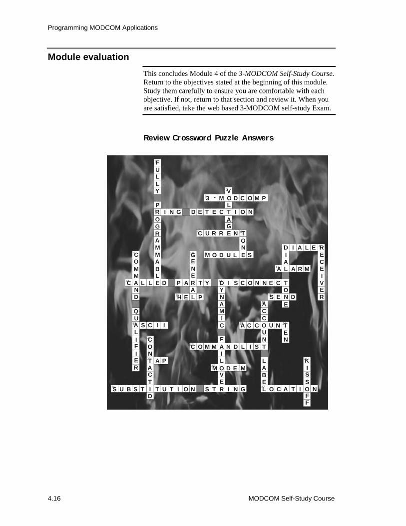
Programming MODCOM Applications
4.16 MODCOM Self-Study Course
Module evaluationThis concludes Module 4 of the 3-MODCOM Self-Study Course.Return to the objectives stated at the beginning of this module.Study them carefully to ensure you are comfortable with eachobjective. If not, return to that section and review it. When youare satisfied, take the web based 3-MODCOM self-study Exam.
Review Crossword Puzzle Answers
1
2
3
4
5 6
7 8
9 10 11
12
13 14
15 16
17
18 19 20
21
22
23 24
25
26 27
FULLY
PROGRAMMABLE
VOLTAGE
3 - M D C O M
I N G D E T E C I O N
C U R R N TONEM O D U L S
D I A L E RECEIVER
IAL
TONE
A A R M
S E D
GENERALH E P
C A L L D P A T Y D I S C O N N E C
COMM
ND
QUALIFIER
S C I I
CONTACTID
A P
S U B S T T U T I O N S T R I N G
YNAMIC
FAILOVE
M D E M
C O M M N D L I S T
ACCOUN
LABEL
A C C U N TEN
O C A T I O N
KISS
FF
P