ess ttl configurator user manual - fluigent · before installing the ess™ttl configurator, log on...
TRANSCRIPT

User Manual
ESSTM TTL Configurator
Version 1A

Page - 2
FLUIGENT
Siège social : Biopark – 1 mail du Professeur Georges Mathé – 94800 Villejuif - France
Tel: +331 77 01 82 68 – Fax: +331 77 01 82 70
www.fluigent.com SA à Directoire et Conseil de Surveillance au capital de 141 284.95 € - Siret : 487 636 409 00038 – N°TVA UE/EU VAT Number : FR 53 487 636 409
1. INTRODUCTION 3
2. SYSTEM REQUIREMENTS 5
3. INSTALLATION INSTRUCTIONS 5
4. HOW TO START 6
5. CREATE NEW ACTION RULES 8
6. MODIFY CURRENT ACTION RULES 13
7. ERASE CURRENT ACTION RULES 14
8. SAVE AND LOAD CONFIGURATION 15
9. GETTING HELP 16
10. TWO EXAMPLES OF USE (INPUT AND OUTPUT CASES) 17
11. FREQUENTLY ASKED QUESTIONS (FAQ) 21

Page - 3
FLUIGENT
Siège social : Biopark – 1 mail du Professeur Georges Mathé – 94800 Villejuif - France
Tel: +331 77 01 82 68 – Fax: +331 77 01 82 70
www.fluigent.com SA à Directoire et Conseil de Surveillance au capital de 141 284.95 € - Siret : 487 636 409 00038 – N°TVA UE/EU VAT Number : FR 53 487 636 409
1. Introduction
The SWITCHBOARD has the capability to take specific actions automatically in response to an external trigger or
to the status of its connected valves.
You can configure its automatic behavior by writing action rules into your SWITCHBOARD. According to these
rules, the SWITCHBOARD can automatically:
• make a valve to change to a specific position after receiving an external trigger (e.g. toggle the position of the 2-SWITCH™ on port 2 when the SWITCHBOARD detects a rising edge trigger on TTL port 3).
• send out a trigger when a connected valve changed position or turned to a specific position (e.g. send out a pulse active high on TTL port 1 when the M-SWITCH™ on port A is turned into position 5).
By receiving/emitting triggers, the SWITCHBOARD can communicate with other devices to synchronize their
actions (these devices are called synchronized devices in the rest of the manual). With these highly-
configurable action rules, you can orchestrate their cooperative function, and build a fully automated set-up
for your needs.
The ESS™ TTL Configurator is the software to edit these action rules and to write them into your
SWITCHBOARD.
In physical level, the SWITCHBOARD and other synchronized devices are connected by the coaxial cables, and
their communication is carried by the TTL digital signal.
What is a TTL signal?
TTL signal is an electric signal for communication between devices, according to certain protocol. This method
is especially used to synchronize some very fast actions (in microseconds) of different devices in the electronic
industry because of its reputation on speed and reliability.
The SWITCHBOARD uses TTL signal to synchronize its actions with other devices. It can receive or send out the
TTL trigger signal and synchronize with up to 4 devices at the same time.
Why use TTL signal to synchronize actions?
A lot of microfluidic devices can be connected to the computer via USB, and in theory the computer can act as
an intermediary to synchronize the actions of these devices.
However, the computer’s architecture and its communication protocols are not designed for synchronized
actions. The computer has a reaction time much longer than that of hardware-based electronic device;
computer’s communication protocols contain unpredictable delays; and especially its reliability cannot be
compared with an electronic device. All these made computer not suitable for microfluidic device
synchronization, if the response time and the reliability are the crucial factors for the success of your
experiment.
Fluigent has designed a dedicated chip in the SWITCHBOARD to apply the user-defined action rules
autonomously and to communicate with other synchronized devices by TTL signal. The SWITCHBOARD and
other synchronized devices can thus be directly connected without passing by the computer.
This hardware-based electronic solution gives the SWITCHBOARD the fastest reaction time and the best
reliability comparing to other solutions in the market. It guarantees the tightest synchronization and the
success of your experiments.

Page - 4
FLUIGENT
Siège social : Biopark – 1 mail du Professeur Georges Mathé – 94800 Villejuif - France
Tel: +331 77 01 82 68 – Fax: +331 77 01 82 70
www.fluigent.com SA à Directoire et Conseil de Surveillance au capital de 141 284.95 € - Siret : 487 636 409 00038 – N°TVA UE/EU VAT Number : FR 53 487 636 409
Details on a digital TTL trigger
A digital TTL trigger signal is composed of two discrete levels: logic low and logic high. The logic low state can
range between the values of 0 to 0.8V. The logic high state can range between the values of 2 to 5V.
The edge that transits between the logic low state to the logic high state is called the rising edge. Likewise, the
edge that transits between the logic high state to the logic low state is called the falling edge.
The SWITCHBOARD can receive digital TTL triggers and can take specific actions in response to a raising edge or
to a falling edge according to user-defined action rules.
The SWITCHBOARD can also send out 2 types of triggers to synchronized devices, according to user-defined
action rules:
logic low state
logic high state
Pulse (trigger) active high Pulse (trigger) active low
logic high state
logic low state
Begin action Begin action
Rising edge Falling edge
100 ms 100 ms

Page - 5
FLUIGENT
Siège social : Biopark – 1 mail du Professeur Georges Mathé – 94800 Villejuif - France
Tel: +331 77 01 82 68 – Fax: +331 77 01 82 70
www.fluigent.com SA à Directoire et Conseil de Surveillance au capital de 141 284.95 € - Siret : 487 636 409 00038 – N°TVA UE/EU VAT Number : FR 53 487 636 409
2. System Requirements
This installation of ESS™TTL Configurator requires one of the following Microsoft operating systems:
• Windows XP Service Pack 3
• Windows Vista (32 and 64 bits)
• Windows 7 (32 and 64 bits)
• Windows 8 (32 and 64 bits)
• Windows 10 (32 and 64 bits)
This installation requires that version 3.1 of the MSI (Windows Installer) Engine is installed on your computer. If
you do not have MSI 3.1 or later, the installer updates the engine automatically and might require that you
restart your computer.
The ESS™TTL Configurator software requires:
• A minimum of 512 Mo of RAM (2Go recommended)
• Minimum process or Intel Pentium 1.6 GHz
• Minimum screen size 800 x 600
3. Installation Instructions
Before installing the ESS™TTL Configurator, log on as Administrator or as a user with Administrator privileges.
The ESS™TTL Configurator software setup program must have Administrator privileges because the program
modifies the configuration registry of your system. Complete the following steps to install the ESS™TTL
Configurator software:
1. Plug your Fluigent USB key. The installer launches if your USB key plays data automatically. If the installer
does not launch automatically, navigate into the USB key files using Windows Explorer and launch the
setup.exe file from your ESS™TTL Configurator software USB key.
2. The installation wizard guides you through the necessary steps to install the ESS™TTL Configurator
software. You can go back and change values by clicking the Back button.
3. When the installation is complete, click Finish.
Page - 6
FLUIGENT
Siège social : Biopark – 1 mail du Professeur Georges Mathé – 94800 Villejuif - France
Tel: +331 77 01 82 68 – Fax: +331 77 01 82 70
www.fluigent.com SA à Directoire et Conseil de Surveillance au capital de 141 284.95 € - Siret : 487 636 409 00038 – N°TVA UE/EU VAT Number : FR 53 487 636 409
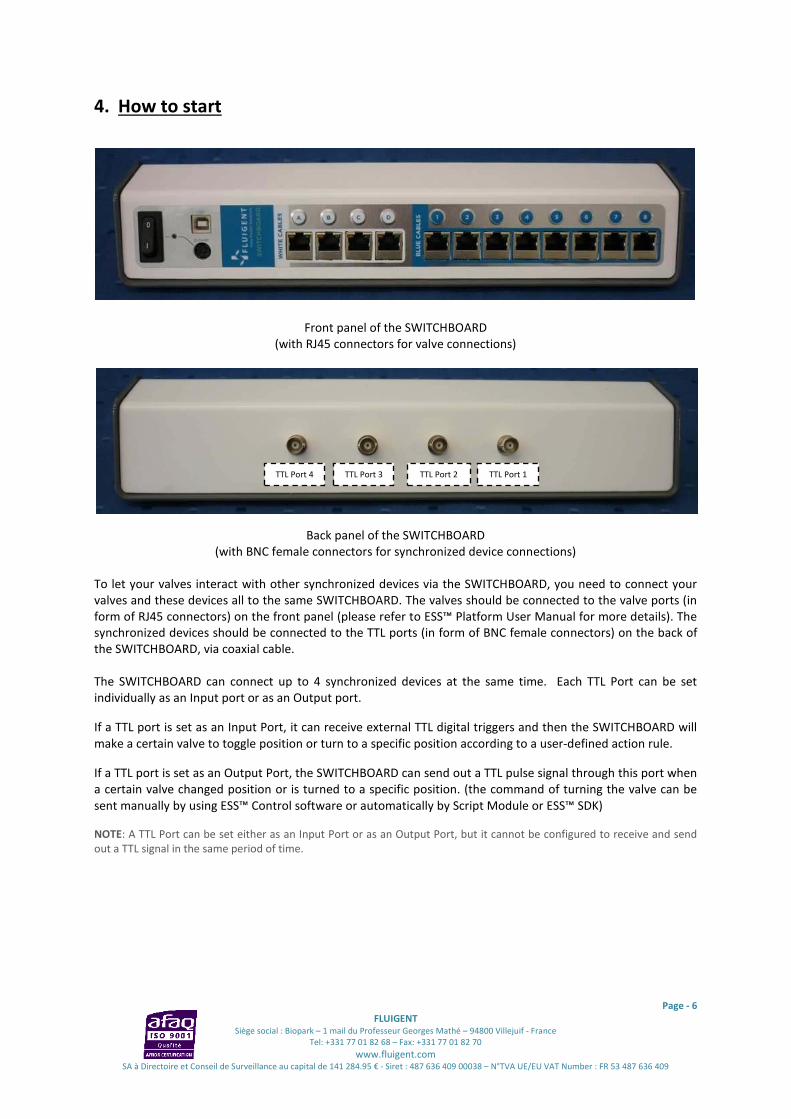
4. How to start
Front panel of the SWITCHBOARD
(with RJ45 connectors for valve connections)
Back panel of the SWITCHBOARD
(with BNC female connectors for synchronized device connections)
To let your valves interact with other synchronized devices via the SWITCHBOARD, you need to connect your
valves and these devices all to the same SWITCHBOARD. The valves should be connected to the valve ports (in
form of RJ45 connectors) on the front panel (please refer to ESS™ Platform User Manual for more details). The
synchronized devices should be connected to the TTL ports (in form of BNC female connectors) on the back of
the SWITCHBOARD, via coaxial cable.
The SWITCHBOARD can connect up to 4 synchronized devices at the same time. Each TTL Port can be set
individually as an Input port or as an Output port.
If a TTL port is set as an Input Port, it can receive external TTL digital triggers and then the SWITCHBOARD will
make a certain valve to toggle position or turn to a specific position according to a user-defined action rule.
If a TTL port is set as an Output Port, the SWITCHBOARD can send out a TTL pulse signal through this port when
a certain valve changed position or is turned to a specific position. (the command of turning the valve can be
sent manually by using ESS™ Control software or automatically by Script Module or ESS™ SDK)
NOTE: A TTL Port can be set either as an Input Port or as an Output Port, but it cannot be configured to receive and send
out a TTL signal in the same period of time.
TTL Port 4 TTL Port 3 TTL Port 2 TTL Port 1
Page - 7
FLUIGENT
Siège social : Biopark – 1 mail du Professeur Georges Mathé – 94800 Villejuif - France
Tel: +331 77 01 82 68 – Fax: +331 77 01 82 70
www.fluigent.com SA à Directoire et Conseil de Surveillance au capital de 141 284.95 € - Siret : 487 636 409 00038 – N°TVA UE/EU VAT Number : FR 53 487 636 409
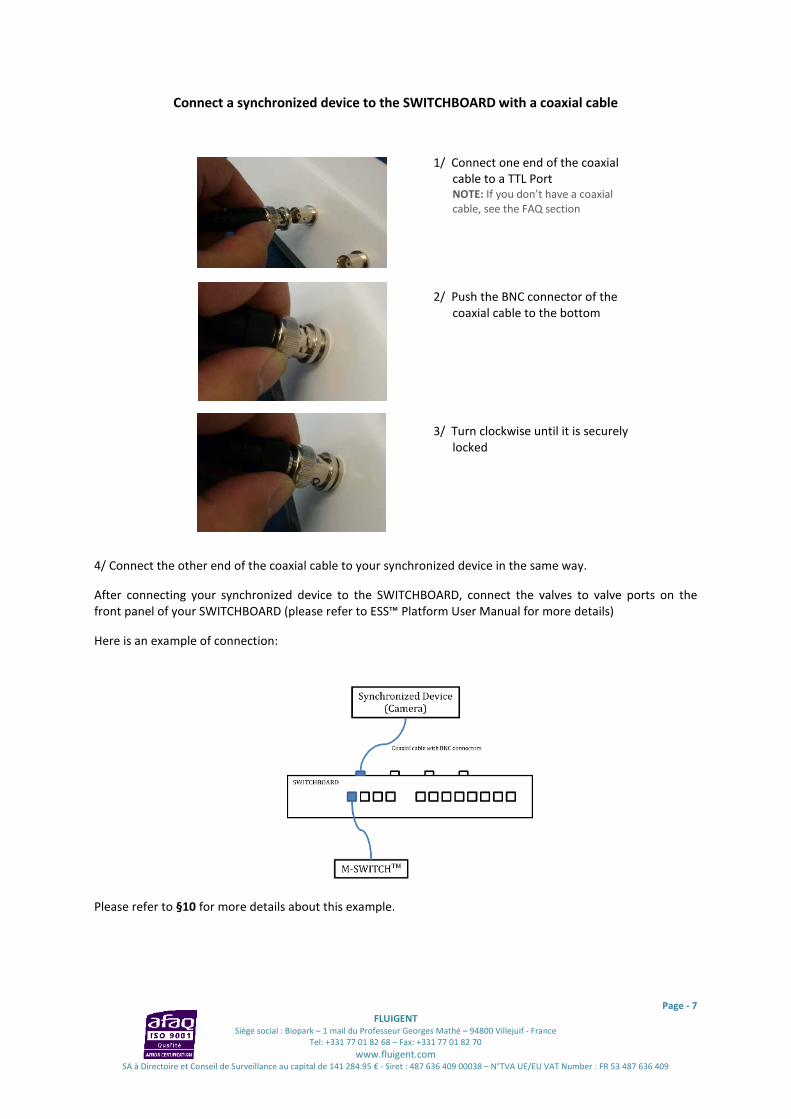
Connect a synchronized device to the SWITCHBOARD with a coaxial cable
1/ Connect one end of the coaxial
cable to a TTL Port
NOTE: If you don’t have a coaxial
cable, see the FAQ section
2/ Push the BNC connector of the
coaxial cable to the bottom
3/ Turn clockwise until it is securely
locked
4/ Connect the other end of the coaxial cable to your synchronized device in the same way.
After connecting your synchronized device to the SWITCHBOARD, connect the valves to valve ports on the
front panel of your SWITCHBOARD (please refer to ESS™ Platform User Manual for more details)
Here is an example of connection:
Please refer to §10 for more details about this example.
Page - 8
FLUIGENT
Siège social : Biopark – 1 mail du Professeur Georges Mathé – 94800 Villejuif - France
Tel: +331 77 01 82 68 – Fax: +331 77 01 82 70
www.fluigent.com SA à Directoire et Conseil de Surveillance au capital de 141 284.95 € - Siret : 487 636 409 00038 – N°TVA UE/EU VAT Number : FR 53 487 636 409
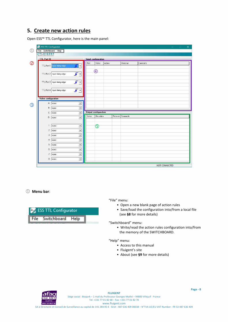
5. Create new action rules
Open ESS™ TTL Configurator, here is the main panel:
Menu bar:
“File” menu:
• Open a new blank page of action rules
• Save/load the configuration into/from a local file
(see §8 for more details)
“Switchboard” menu:
• Write/read the action rules configuration into/from
the memory of the SWITCHBOARD.
“Help” menu:
• Access to this manual
• Fluigent’s site
• About (see §9 for more details)
�
�
�
�
�
�

Page - 9
FLUIGENT
Siège social : Biopark – 1 mail du Professeur Georges Mathé – 94800 Villejuif - France
Tel: +331 77 01 82 68 – Fax: +331 77 01 82 70
www.fluigent.com SA à Directoire et Conseil de Surveillance au capital de 141 284.95 € - Siret : 487 636 409 00038 – N°TVA UE/EU VAT Number : FR 53 487 636 409
TTL Port IO:
Set the Input/Output mode for each TTL Port
Input Rising Edge: This TTL port is set as Input port and will
receive external TTL signal. When it detects a rising edge
triggering event, the SWITCHBOARD will apply an action rule
associated with this port in the Input configuration section.
Input Falling Edge: This TTL port is set as Input port and will
receive external TTL signal. When it detects a falling edge
triggering event, the SWITCHBOARD will apply an action rule
associated with this port in the Input configuration section.
Output Active Low: This TTL port is set as Output port and will
send out a TTL active low pulse (trigger), when the condition
of an action rule is met in the Output configuration section.
Output Active High: This TTL port is set as Output port and
will send out a TTL active high pulse (trigger), when the
condition of an action rule is met in the Output configuration
section.
NOTE: See §1 for more details
Valve Configuration:
Tell ESS™ TTL Configurator which valves are connected to the
SWITCHBOARD.
NOTE: Please give exactly the same configuration as how the valves
are connected to the SWITCHBOARD, otherwise errors may occur.
Form Port A to D:
Set “none” if no valve is connected to this port
Set “M-SWITCH” if a M-SWITCH™ is connected to this port
Set “L-SWITCH” if a L-SWITCH™ is connected to this port
Form Port 1 to Port 8:
Set “none” if no valve is connected to this port
Set “2-SWITCH” if a 2-SWITCH™ is connected to this port
�
�

Page - 10
FLUIGENT
Siège social : Biopark – 1 mail du Professeur Georges Mathé – 94800 Villejuif - France
Tel: +331 77 01 82 68 – Fax: +331 77 01 82 70
www.fluigent.com SA à Directoire et Conseil de Surveillance au capital de 141 284.95 € - Siret : 487 636 409 00038 – N°TVA UE/EU VAT Number : FR 53 487 636 409
Input Configuration:
In each line, you can write an action rule associated with an
Input TTL port:
When this port detects a triggering event, make a certain
valve change position or turn to a specific position
NOTE: the order of each action rule line has no effect on the
functional results.
Port: The Input TTL Port for the detection of triggering event.
Only the TTL port set as Input Port in the TTL Port IO section will be available here.
Valve: The port of valve you want to activate, in response to the triggering event.
Only the valves added in the Valve Configuration section will be available here.
Action: the action you want the Valve to take
For each type of valve, you have different choices:
M-SWITCH™: position 1 to position 10, next position and previous position
L-SWITCH™: position 1, position 2 and toggle position
2-SWITCH™: position 1, position 2 and toggle position
Example: When TTL Port 1 detects a triggering
event, make the 2-SWITCH™ at port 1 to turn to
position 2. (See §10 for the whole example)
Direction: M-SWITCH™ exclusive option. You can choose from “Shortest”, “Clockwise” and “Anticlockwise”
for M-SWITCH™ rotation direction.
Comments: You can add your personal remarks for this line for future reference.
NOTE: these comments cannot be written into the memory of your SWITCHBOARD, and thus cannot be
fetched if you read your configuration from the SWITCHBOARD. If you want to save these comments, use the
Save feature to save the entire configuration with comments into a file on your local computer. Please refer to
§8 for more details.
Output Configuration:
In each line, you can write an action rule associated with an
Output TTL port:
When a certain valve changed position or turn to a specific
position, send out a pulse through this port.
NOTE: the order of each action rule line has no effect on the
functional results.
�
�

Page - 11
FLUIGENT
Siège social : Biopark – 1 mail du Professeur Georges Mathé – 94800 Villejuif - France
Tel: +331 77 01 82 68 – Fax: +331 77 01 82 70
www.fluigent.com SA à Directoire et Conseil de Surveillance au capital de 141 284.95 € - Siret : 487 636 409 00038 – N°TVA UE/EU VAT Number : FR 53 487 636 409
Valve: The port of the valve you want to monitor its status.
Only the valves configured in the Valve Configuration section will be available here.
On action: When the valve is on this action or position, it is the condition to send out a TTL pulse signal on the
designated TTL output port.
For each type of valve, you have different choices:
M-SWITCH™: position 1 to position 10 and change position
L-SWITCH™: position 1, position 2 and change position
2-SWITCH™: position 1, position 2 and change position
Pulse on: The TTL output port associated with this action rule: the TTL pulse signal will be sent out through
this port.
Only the TTL port set as Output Port in the TTL Port IO section will be available here.
Example: When the valve at port A (here is an M-
SWITCH™) turns to position 8, send out a pulse on
TTL port 1 (See §10 for the whole example)
Comments: You can add your personal remarks for this line for future reference.
NOTE: these comments cannot be written into the memory of your SWITCHBOARD, and thus cannot be
fetched if you read your configuration from the SWITCHBOARD. If you want to save these comments, use the
Save feature to save the entire configuration with comments into a file on your local computer. Please refer to
§8 for more details.
NOTE: These previous configurations can be done without connecting your SWITCHBOARD to the computer. The
SWITCHBOARD only needs to be connected the moment when you write these configurations into your SWITCHBOARD.
Write action rules into your SWITCHBOARD
Once you finish editing your action rules, you now need to write them into the memory of your SWITCHBOARD
in order to let them occur.
Before writing these action rules, please verify that:
• In Valve configuration section, all is set exactly as how the valves are connected to
the SWITCHBOARD.
• There is no conflict in the Input or Output configuration.
(e.g. Under the same triggering event, a valve is not set to turn to 2 different positions in 2
lines of action rules)
Begin to write the action rules into your SWITCHBOARD
1. Connect your SWITCHBOARD to your computer via USB and power it on. In the lower right corner of
ESS™ TTL Configurator main panel, the status bar will change from to
Click “Switchboard” menu and then “Write configuration”
2. If everything goes well, you will see a success dialog window. The new action rules will take effect
immediately (no reboot of your SWITCHBOARD is needed).

Page - 12
FLUIGENT
Siège social : Biopark – 1 mail du Professeur Georges Mathé – 94800 Villejuif - France
Tel: +331 77 01 82 68 – Fax: +331 77 01 82 70
www.fluigent.com SA à Directoire et Conseil de Surveillance au capital de 141 284.95 € - Siret : 487 636 409 00038 – N°TVA UE/EU VAT Number : FR 53 487 636 409
NOTE 1: The action rules are stored inside the SWITCHBOARD memory will be kept even when it is powered off.
NOTE 2: If you see the “No Connection” dialog window, please verify your SWITCHBOARD is powered on and is
securely connected to your computer via the USB cable.
Page - 13
FLUIGENT
Siège social : Biopark – 1 mail du Professeur Georges Mathé – 94800 Villejuif - France
Tel: +331 77 01 82 68 – Fax: +331 77 01 82 70
www.fluigent.com SA à Directoire et Conseil de Surveillance au capital de 141 284.95 € - Siret : 487 636 409 00038 – N°TVA UE/EU VAT Number : FR 53 487 636 409
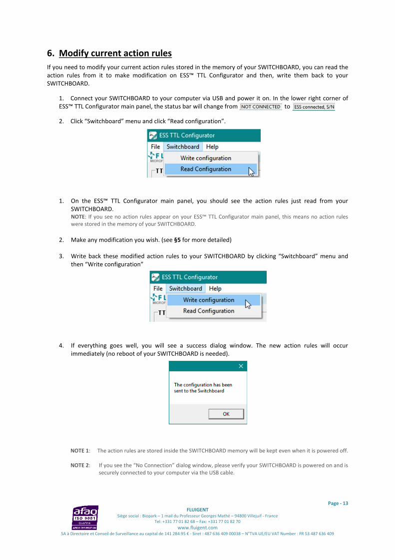
6. Modify current action rules
If you need to modify your current action rules stored in the memory of your SWITCHBOARD, you can read the
action rules from it to make modification on ESS™ TTL Configurator and then, write them back to your
SWITCHBOARD.
1. Connect your SWITCHBOARD to your computer via USB and power it on. In the lower right corner of
ESS™ TTL Configurator main panel, the status bar will change from to
2. Click “Switchboard” menu and click “Read configuration”.
1. On the ESS™ TTL Configurator main panel, you should see the action rules just read from your
SWITCHBOARD.
NOTE: If you see no action rules appear on your ESS™ TTL Configurator main panel, this means no action rules
were stored in the memory of your SWITCHBOARD.
2. Make any modification you wish. (see §5 for more detailed)
3. Write back these modified action rules to your SWITCHBOARD by clicking “Switchboard” menu and
then “Write configuration”
4. If everything goes well, you will see a success dialog window. The new action rules will occur
immediately (no reboot of your SWITCHBOARD is needed).
NOTE 1: The action rules are stored inside the SWITCHBOARD memory will be kept even when it is powered off.
NOTE 2: If you see the “No Connection” dialog window, please verify your SWITCHBOARD is powered on and is
securely connected to your computer via the USB cable.

Page - 14
FLUIGENT
Siège social : Biopark – 1 mail du Professeur Georges Mathé – 94800 Villejuif - France
Tel: +331 77 01 82 68 – Fax: +331 77 01 82 70
www.fluigent.com SA à Directoire et Conseil de Surveillance au capital de 141 284.95 € - Siret : 487 636 409 00038 – N°TVA UE/EU VAT Number : FR 53 487 636 409
7. Erase current action rules
If you want to stop your SWITCHBOARD from reacting automatically to any external trigger and from sending
out any TTL pulse, you need to erase all current action rules.
To achieve that, you only need to create a blank action rules configuration and write it to your SWITCHBOARD.
To create a blank action rules configuration: click “File” menu and then “New”.
You should see a clean main panel. Then write these blank rules to your SWITCHBOAR by clicking “Switchboard”
menu and then “Write configuration”. (See §5 for more details)

Page - 15
FLUIGENT
Siège social : Biopark – 1 mail du Professeur Georges Mathé – 94800 Villejuif - France
Tel: +331 77 01 82 68 – Fax: +331 77 01 82 70
www.fluigent.com SA à Directoire et Conseil de Surveillance au capital de 141 284.95 € - Siret : 487 636 409 00038 – N°TVA UE/EU VAT Number : FR 53 487 636 409
8. Save and Load configuration
You can save your action rules configuration to a local file in your computer and load it in the future.
• Save an action rules configuration:
1. Click “File” menu and then “Save configuration”
2. Choose a path on your computer where you can easily find and give a name to the file
3. Click “Save”
The ESS™ TTL Configurator will save a cfg format file under C:\Fluigent\ESS TTL.
NOTE: the comments of each line of action rule will also be saved in this file.
• Load an action rules configuration:
1. Click “File” menu and then “Load configuration”
2. Choose the cfg file of the configuration you saved earlier
3. Click “Load”
You should be able to see all the action rules you saved appear on your ESS™ TTL Configurator main panel.
Attention: These action rules are now only loaded to your ESS™ TTL Configurator software. If you want them to
occur, you will need to write them into your SWITCHBOARD: click on “Switchboard” menu and then “Write
configuration”. (see §5 for more details on writing rules into the SWITCHBOARD)

Page - 16
FLUIGENT
Siège social : Biopark – 1 mail du Professeur Georges Mathé – 94800 Villejuif - France
Tel: +331 77 01 82 68 – Fax: +331 77 01 82 70
www.fluigent.com SA à Directoire et Conseil de Surveillance au capital de 141 284.95 € - Siret : 487 636 409 00038 – N°TVA UE/EU VAT Number : FR 53 487 636 409
9. Getting help
When using the ESS™ TTL Configurator, you can get access to this user manual by clicking “Help” menu then
“User manual”.
You can also click on the “Fluigent Website” to get various application notes and information on other products
on microfluidics.
If you can’t find any answer to your questions, you can always contact our technical support team
([email protected]), who will be willing to help you solving problems and designing new set-up and
applications.

Page - 17
FLUIGENT
Siège social : Biopark – 1 mail du Professeur Georges Mathé – 94800 Villejuif - France
Tel: +331 77 01 82 68 – Fax: +331 77 01 82 70
www.fluigent.com SA à Directoire et Conseil de Surveillance au capital de 141 284.95 € - Siret : 487 636 409 00038 – N°TVA UE/EU VAT Number : FR 53 487 636 409
10. Two examples of use (Input and Output cases)
Here we present two examples using the ESS™ TTL Configurator. The first one is to turn a valve in response of
an external triggers; the second one is to send out a TTL pulse when a valve is in a specific position. These
examples may help you to better understand the settings procedures.
Example 1 (Input case: receive external triggers)
In the laboratory, we produce a continuous flow of blue and red droplets and we want to sort these droplets
according to their colors. When a droplet is blue, we want to orient it to the reservoir 1; when it is red, we
want to orient it to the reservoir 2.
To achieve this, we use a programmable smart camera to work with a 2-SWITCH™.
Here is an illustration of how we want the system to work.
The smart camera has multiple trigger out ports. We can program it in this way: when detecting a blue droplet,
send out a trigger through its Trigger Out port 1; when detecting a red droplet, send out a trigger through its
Trigger Out port 2.
These triggers are sent to the SWITCHBOARD. When the SWITCHBOARD receives the TTL trigger from the
Trigger Out port 1 of the camera, the SWITCHBOARD knows that it is a blue droplet and will turn the 2-
SWITCH™ to position 1, so the blue droplet is oriented to the reservoir1. Similarly, when the SWITCHBOARD get
the trigger form the Trigger Out port 2 of the camera, it will orient the flow to the reservoir 2.
Here are the configuration steps for the SWITCHBOARD:
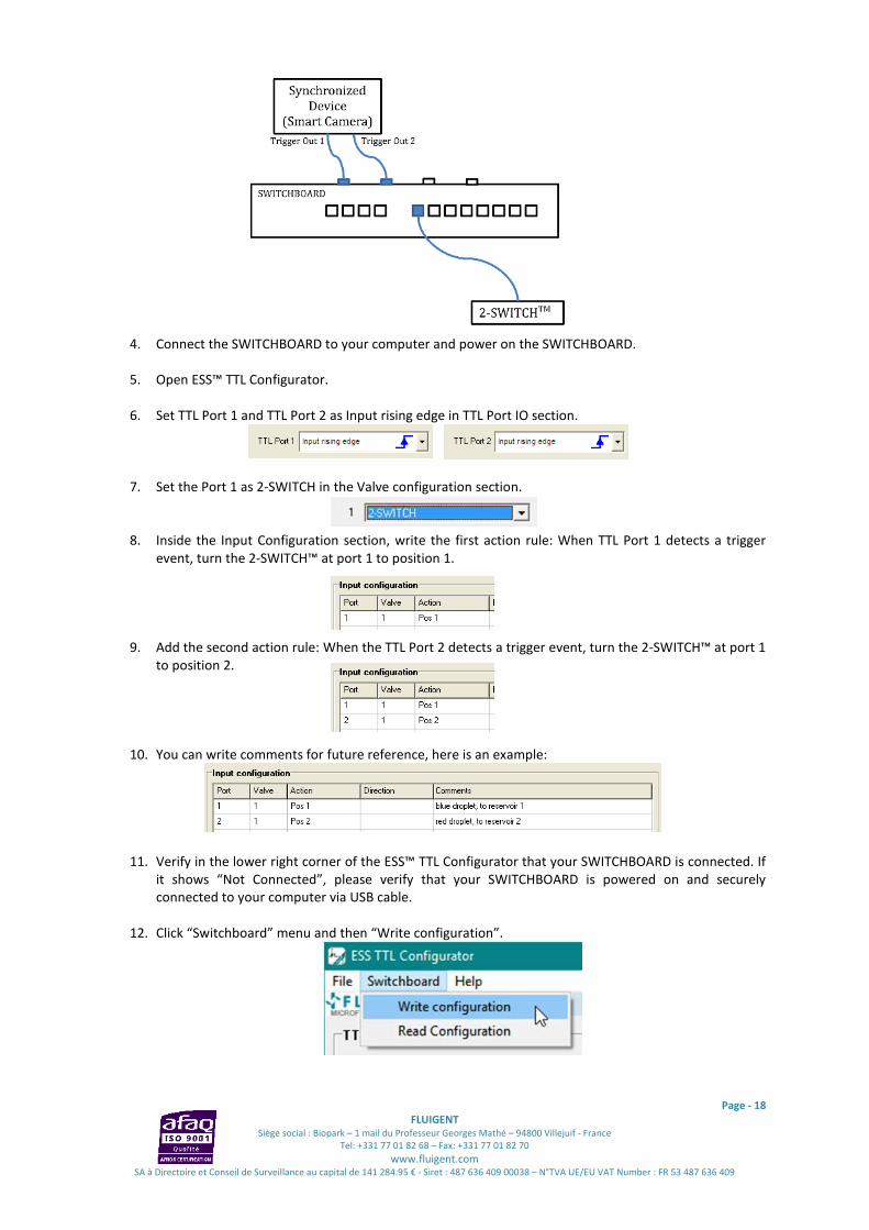
1. Connect the Trigger Out port 1 of the smart camera to a TTL port of the SWITCHBOARD (for example
TTL Port 1 here), by using a coaxial cable.
2. Connect the Trigger Out port 2 of the smart camera to a TTL port of the SWITCHBOARD (for example
TTL Port 2 here), by using a coaxial cable.
3. Connect the 2-SWITCH™ to a 2-SWITCH Port (blue cables section) of the SWITCHBOARD (for example
Port 1 here), by using a blue RJ45 cable provided with the 2-SWITCH™.
When the droplet detected is blue, the 2-SWITCH™ orient
the flow to reservoir 1. When the droplet detected is red, the 2-SWITCH™
change to position 2, leading the flow to reservoir 2.
Page - 18
FLUIGENT
Siège social : Biopark – 1 mail du Professeur Georges Mathé – 94800 Villejuif - France
Tel: +331 77 01 82 68 – Fax: +331 77 01 82 70
www.fluigent.com SA à Directoire et Conseil de Surveillance au capital de 141 284.95 € - Siret : 487 636 409 00038 – N°TVA UE/EU VAT Number : FR 53 487 636 409
4. Connect the SWITCHBOARD to your computer and power on the SWITCHBOARD.
5. Open ESS™ TTL Configurator.
6. Set TTL Port 1 and TTL Port 2 as Input rising edge in TTL Port IO section.
7. Set the Port 1 as 2-SWITCH in the Valve configuration section.
8. Inside the Input Configuration section, write the first action rule: When TTL Port 1 detects a trigger
event, turn the 2-SWITCH™ at port 1 to position 1.
9. Add the second action rule: When the TTL Port 2 detects a trigger event, turn the 2-SWITCH™ at port 1
to position 2.
10. You can write comments for future reference, here is an example:
11. Verify in the lower right corner of the ESS™ TTL Configurator that your SWITCHBOARD is connected. If
it shows “Not Connected”, please verify that your SWITCHBOARD is powered on and securely
connected to your computer via USB cable.
12. Click “Switchboard” menu and then “Write configuration”.
Page - 19
FLUIGENT
Siège social : Biopark – 1 mail du Professeur Georges Mathé – 94800 Villejuif - France
Tel: +331 77 01 82 68 – Fax: +331 77 01 82 70
www.fluigent.com SA à Directoire et Conseil de Surveillance au capital de 141 284.95 € - Siret : 487 636 409 00038 – N°TVA UE/EU VAT Number : FR 53 487 636 409
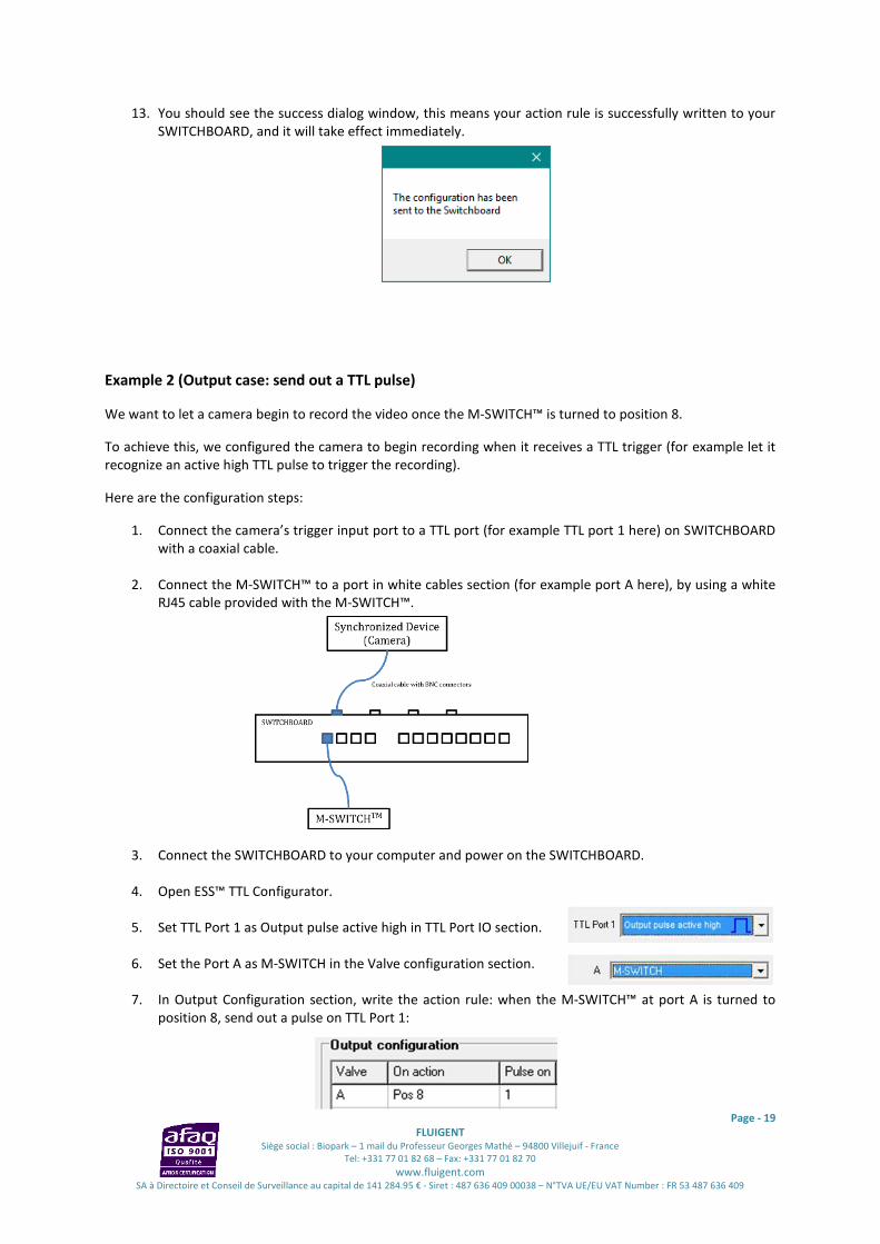
13. You should see the success dialog window, this means your action rule is successfully written to your
SWITCHBOARD, and it will take effect immediately.
Example 2 (Output case: send out a TTL pulse)
We want to let a camera begin to record the video once the M-SWITCH™ is turned to position 8.
To achieve this, we configured the camera to begin recording when it receives a TTL trigger (for example let it
recognize an active high TTL pulse to trigger the recording).
Here are the configuration steps:
1. Connect the camera’s trigger input port to a TTL port (for example TTL port 1 here) on SWITCHBOARD
with a coaxial cable.
2. Connect the M-SWITCH™ to a port in white cables section (for example port A here), by using a white
RJ45 cable provided with the M-SWITCH™.
3. Connect the SWITCHBOARD to your computer and power on the SWITCHBOARD.
4. Open ESS™ TTL Configurator.
5. Set TTL Port 1 as Output pulse active high in TTL Port IO section.
6. Set the Port A as M-SWITCH in the Valve configuration section.
7. In Output Configuration section, write the action rule: when the M-SWITCH™ at port A is turned to
position 8, send out a pulse on TTL Port 1:

Page - 20
FLUIGENT
Siège social : Biopark – 1 mail du Professeur Georges Mathé – 94800 Villejuif - France
Tel: +331 77 01 82 68 – Fax: +331 77 01 82 70
www.fluigent.com SA à Directoire et Conseil de Surveillance au capital de 141 284.95 € - Siret : 487 636 409 00038 – N°TVA UE/EU VAT Number : FR 53 487 636 409
8. You can write a comment for future reference, here is an example:
9. Verify in the lower right corner of the ESS™ TTL Configurator that your SWITCHBOARD is connected.
If it shows “Not Connected”, please verify that your SWITCHBOARD is powered on and securely
connected to your computer via USB cable.
10. Click “Switchboard” menu and then “Write configuration”.
11. You should see the success dialog window, this means your action rule is successfully written to your
SWITCHBOARD, and it will occur immediately.

Page - 21
FLUIGENT
Siège social : Biopark – 1 mail du Professeur Georges Mathé – 94800 Villejuif - France
Tel: +331 77 01 82 68 – Fax: +331 77 01 82 70
www.fluigent.com SA à Directoire et Conseil de Surveillance au capital de 141 284.95 € - Siret : 487 636 409 00038 – N°TVA UE/EU VAT Number : FR 53 487 636 409
11. Frequently Asked Questions (FAQ)
Which one is the TTL port 1?
The count is from left to right viewing from the front panel. If you see from the back panel, it’s the TTL port 4 at
the end of left. Here is a picture viewing from the back panel:
How should I connect my valves to my SWITCHBOARD?
You should use the straight-through wired RJ45 cables to connect your valves to the SWITCHBOARD (Fluigent
advises to only use the cables provided with the ESS™ Platform). The four first ports in the white cables section
(port A to port D) on the front panel are for connection with M-SWTICH™ or L-SWITCH™. The next eight ports
in the blue cables section (from port 1 to port 8) on the front panel are for connection with 2-SWITCH™. Please
refer to ESS™ Platform User Manual for more details.
How should I connect my synchronized devices to my SWITCHBOARD?
You should use the 50 ohm coaxial cable with BNC connectors to connect your synchronized devices to your
SWITCHBOARD. These connection ports on the SWITCHBOARD are called TTL ports and are located at the back
panel as shown in the photo above.
NOTE: If you don’t have a 50 ohm coaxial cable, you can easily command on the Internet, here is an example from
Radiospare: reference 742-4315
Are these TTL ports Input ports or Output ports?
They can be individually defined by User. A TTL port can be set to as an Input port which detects an external
trigger; or it can be set as an Output port which sends out TTL pulse trigger. Please refer to §5 for more details.
Can I use the ESS™ TTL Configurator and save the configuration when my SWITCHBOARD is not connected?
Yes, you can use ESS™ TTL Configurator to edit the action rules or to save these action rules in a local file
without SWITCHBOARD connected to your computer. You only need to connect your SWITCHBOARD when you
want to write these action rules into your SWITCHBOARD. Once the writing procedure finished, you can
disconnect your SWITCHBOARD. These action rules are stored in the internal memory of SWITCHBOARD, and
will be kept even when the SWITCHBOARD is powered off.
NOTE: Before writing action rules into your SWITCHBOARD, you need to verify the valves are connected to the
SWITCHBOARD exactly as you configured in the Valve configuration section and there is no conflict among the action rules.
Does the former SWITCHBOARD support the trigger feature?
Only the SWITCHBOARD with the BNC connectors on the back panel supports the TTL trigger feature. If you try
to write the TTL configuration and action rules into a former SWITCHBOARD, the following error dialog box will
appear.
TTL Port 4 TTL Port 3 TTL Port 2 TTL Port 1

Page - 22
FLUIGENT
Siège social : Biopark – 1 mail du Professeur Georges Mathé – 94800 Villejuif - France
Tel: +331 77 01 82 68 – Fax: +331 77 01 82 70
www.fluigent.com SA à Directoire et Conseil de Surveillance au capital de 141 284.95 € - Siret : 487 636 409 00038 – N°TVA UE/EU VAT Number : FR 53 487 636 409
FLUIGENT
Biopark
1 mail du Professeur Georges Mathé
94800 Villejuif
FRANCE
Phone : +331 77 01 82 68
Fax : +331 77 01 82 70
www.fluigent.com
Technical support:
Phone: +331 77 01 82 65
General information: