eso 210 introduction to electrical engineering - iit kanpurhome.iitk.ac.in/~sarjun/eso203a/eso 210...
TRANSCRIPT

ESO 210
Introduction to Electrical Engineering Lecture-22
Transformers

2 After going through this lecture students will be able to answer the following questions.

3
After developing the equivalent circuit representation, it is natural to ask, how to know equivalent circuit the parameter values. Theoretically from the detailed design data it is possible to estimate various parameters shown in the equivalent circuit.
In practice, two basic tests namely the open circuit test and the short circuit test are performed to determine the equivalent circuit parameters.

4
For a given transformer of rating say, 10 kVA, 200 V / 100 V, 50 Hz, one should not be under the impression that 200 V (HV) side will always be the primary (as because this value appears first in order in the voltage specification) and 100 V (LV) side will always be secondary. Thus, for a given transformer either of the HV and LV sides may be used as primary or secondary as decided by the user to suit his/her goals in practice. Usuallysuffixes 1 and 2 are used for expressing quantities in terms of primary and secondary respectively – there is nothing wrong in it so long one keeps track clearly which side is being used as primary. However, there are situation, such as carrying out O.C. & S.C tests (to be discussed ahead), where naming parameters with suffixes HV and LV become imperative to avoid mix up or confusion. Thus, it will be useful to qualify the parameter values using the suffixes HV and
LV (such as reHV, reLV etc. instead of re1 , re2 ). Therefore, it is recommended to
use suffixes as LV, HV instead of 1 and 2 while describing quantities (like voltage VHV, VLVand currents IHV, ILV).

5
6
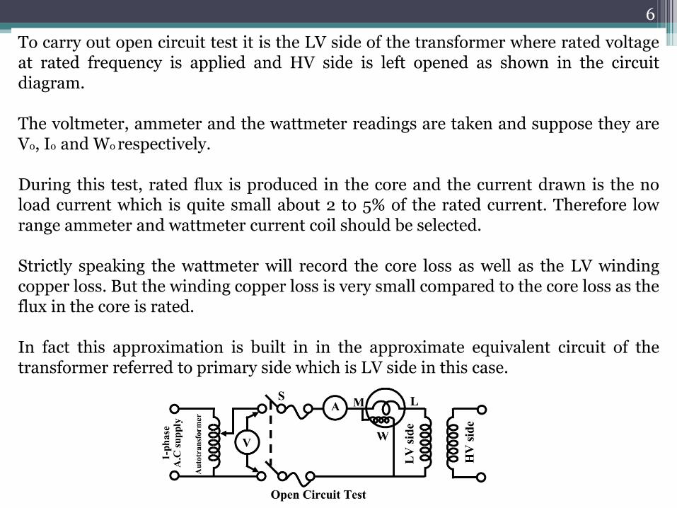
To carry out open circuit test it is the LV side of the transformer where rated voltage at rated frequency is applied and HV side is left opened as shown in the circuit diagram. The voltmeter, ammeter and the wattmeter readings are taken and suppose they are V0, I0 and W0 respectively. During this test, rated flux is produced in the core and the current drawn is the no load current which is quite small about 2 to 5% of the rated current. Therefore low range ammeter and wattmeter current coil should be selected. Strictly speaking the wattmeter will record the core loss as well as the LV winding copper loss. But the winding copper loss is very small compared to the core loss as the flux in the core is rated. In fact this approximation is built in in the approximate equivalent circuit of the transformer referred to primary side which is LV side in this case.

7

8
now

9
10
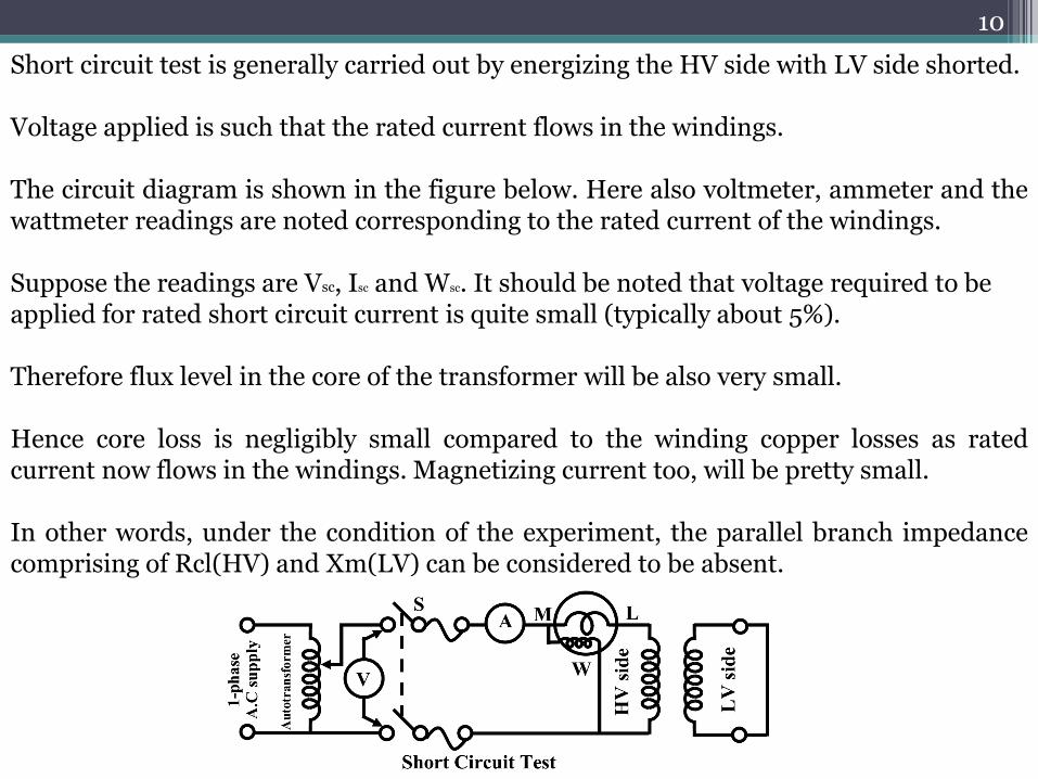
Short circuit test is generally carried out by energizing the HV side with LV side shorted. Voltage applied is such that the rated current flows in the windings. The circuit diagram is shown in the figure below. Here also voltmeter, ammeter and the wattmeter readings are noted corresponding to the rated current of the windings. Suppose the readings are Vsc, Isc and Wsc. It should be noted that voltage required to be applied for rated short circuit current is quite small (typically about 5%). Therefore flux level in the core of the transformer will be also very small. Hence core loss is negligibly small compared to the winding copper losses as rated current now flows in the windings. Magnetizing current too, will be pretty small. In other words, under the condition of the experiment, the parallel branch impedance comprising of Rcl(HV) and Xm(LV) can be considered to be absent.
11
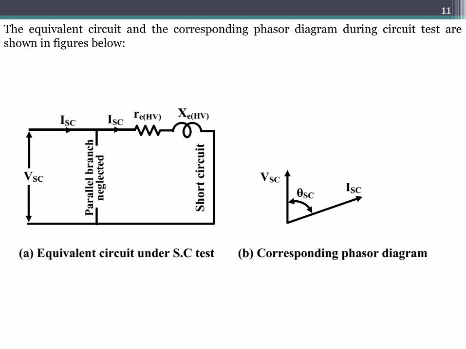
The equivalent circuit and the corresponding phasor diagram during circuit test are shown in figures below:
12
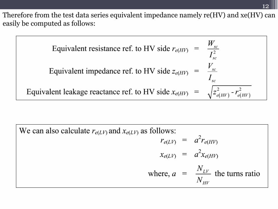
Therefore from the test data series equivalent impedance namely re(HV) and xe(HV) can easily be computed as follows:
13
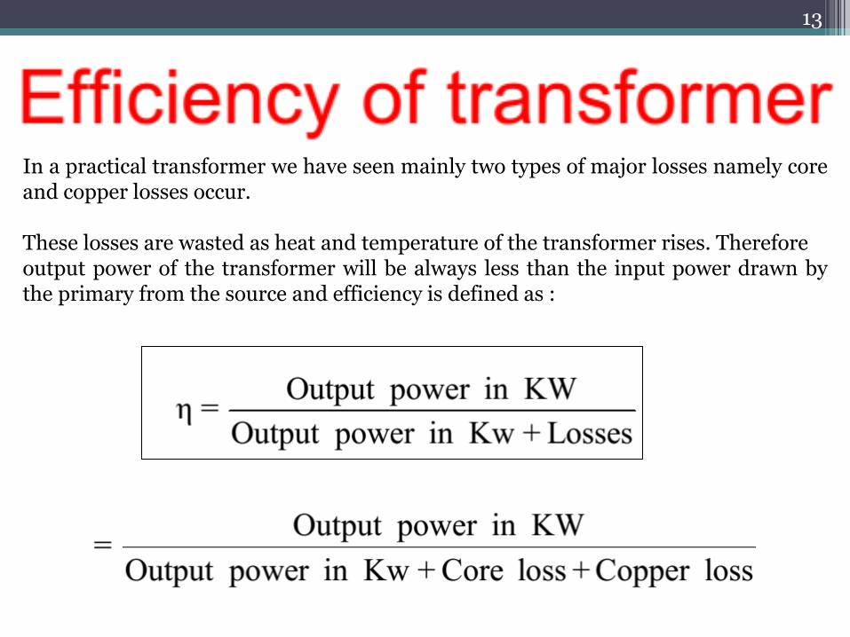
In a practical transformer we have seen mainly two types of major losses namely core and copper losses occur. These losses are wasted as heat and temperature of the transformer rises. Therefore output power of the transformer will be always less than the input power drawn by the primary from the source and efficiency is defined as :
14
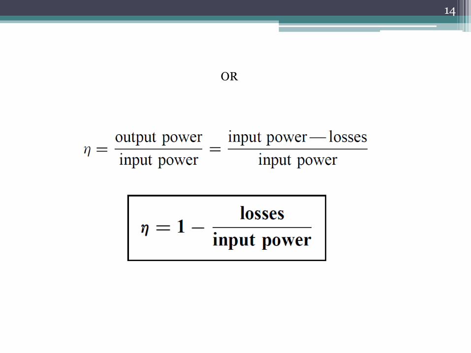
OR

15
The output voltage in a transformer will not be maintained constant from no load to the full load condition, for a fixed input voltage in the primary. This is because there will be internal voltage drop in the series leakage impedance of the transformer the magnitude of which will depend upon the degree of loading as well as on the power factor of the load. The knowledge of regulation gives us idea about change in the magnitude of the secondary voltage from no load to full load condition at a given power factor. This can be determined experimentally by direct loading of the transformer. To do this, primary is energized with rated voltage and the secondary terminal voltage is recorded in absence of any load and also inpresence of full load. Suppose the readings of the voltmeters are respectively V20 and V2. Therefore change in the magnitudes of the secondary voltage is V20– V2. This change is expressed as a percentage of the no load secondary voltage to express regulation. Lower value of regulation will ensure lesser fluctuation of the voltage across the loads. If the transformer were ideal regulation would have been zero.

16
For a well designed transformer at full load and 0.8 power factor load percentage regulation may lie in the range of 2 to 5%. However, it is often not possible to fully load a large transformer in the laboratory in order to know the value of regulation. Theoretically one can estimate approximately, regulation from the equivalent circuit. For this purpose let us draw the equivalent circuit of the transformer referred to the secondary side and neglect the effect of no load current as shown in the figure.

17

18

19

20

21
Magnetostriction:
Magnetic flux in a ferromagnetic material, such as the core, causes it to physically expand
and contract slightly with each cycle of the magnetic field, an effect known
as magnetostriction. This produces the buzzing sound commonly associated with
transformers and can cause losses due to frictional heating.
Mechanical losses:
In addition to magnetostriction, the alternating magnetic field causes fluctuating forces
between the primary and secondary windings. These incite vibrations within nearby
metalwork, adding to the buzzing noise, and consuming a small amount of power.
Stray losses:
Leakage inductance is by itself largely lossless, since energy supplied to its magnetic fields
is returned to the supply with the next half-cycle. However, any leakage flux that intercepts
nearby conductive materials such as the transformer's support structure will give rise to
eddy currents and be converted to heat. There are also radiative losses due to the
oscillating magnetic field, but these are usually small.
Some additional minor losses:

22
Problem: A 2400 V/400 V single-phase transformer takes a no-load current of 0.5 A and the core loss is 400 W. Determine the values of the magnetizing and core loss components of the no-load current. Draw to scale the no-load phasor diagram for the transformer.
Solution:

23
Transformer Construction
There are broadly two types of single-phase double-wound transformer constructions—the core type and the shell type, as shown in Figure below. The low and high voltage windings are wound as shown to reduce leakage flux.
Core type Shell type

24
•For power transformers, rated possibly at several MVA and operating at a frequency of 50 Hz in India, the core material used is usually laminated silicon steel or stalloy, the laminations reducing eddy currents and the silicon steel keeping hysteresis loss to a minimum. •Large power transformers are used in the main distribution system and in industrial supply circuits. Small power transformers have many applications, examples including welding and rectifier supplies, domestic bell circuits, imported washing machines and so on.
For audio frequency (a.f.) transformers, rated from a few mVA and operating at frequencies up to about 15 kHz, the small core is also made of laminated silicon steel. A typical application of a.f. transformers is in an audio amplifier.
Radio frequency (r.f.) transformers, operating in the MHz frequency region have either an air core, a ferrite core or a dust core. Ferrite is a ceramic material having magnetic properties similar to silicon steel, but having a high resistivity. Dust cores consist of fine particles of carbonyl iron or permalloy (i.e. nickel and iron), each particle of which is insulated from its neighbour. Applications of r.f. transformers are found in radio and television receivers.

25
Transformer windings are usually of enamel-insulated copper or aluminium.
Cooling is achieved by air in small transformers and oil in large transformers.

26
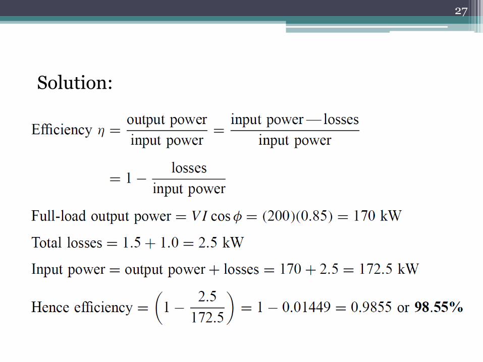
Problem: A 200 kVA rated transformer has a full-load copper loss of 1.5 kW and an iron loss of 1 kW. Determine the transformer efficiency at full load and 0.85 power factor.
27
Solution:
28
Problem: Determine the efficiency of the transformer in previous Problem at half full-load and 0.85 power factor.
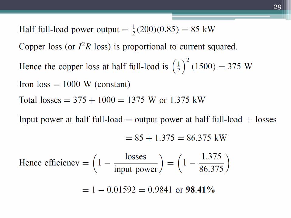
29

30
A 400 kVA transformer has a primary winding resistance of 0.5 and a secondary winding resistance of 0.001 . The iron loss is 2.5 kW and the primary and secondary voltages are 5 kV and 320 V respectively. If the power factor of the load is 0.85, determine the efficiency of the transformer (a) on full load, and (b) on half load.
Problem:

31
Solution:

32

33

34
Equivalent circuit of a Practical Transformer
R1 and R2 represent the resistances of the primary and secondary windings and X1 and X2 represent the reactances of the primary and secondary windings, due to leakage flux.
The core losses due to hysteresis and eddy currents are allowed for by resistance R which takes a current Ic, the core loss component of the primary current. Reactance X takes the magnetizing component IM.

35
R and X are omitted since the no-load current I0 is normally only about 3–5% of the full load primary current.
Transformer on no-load

36
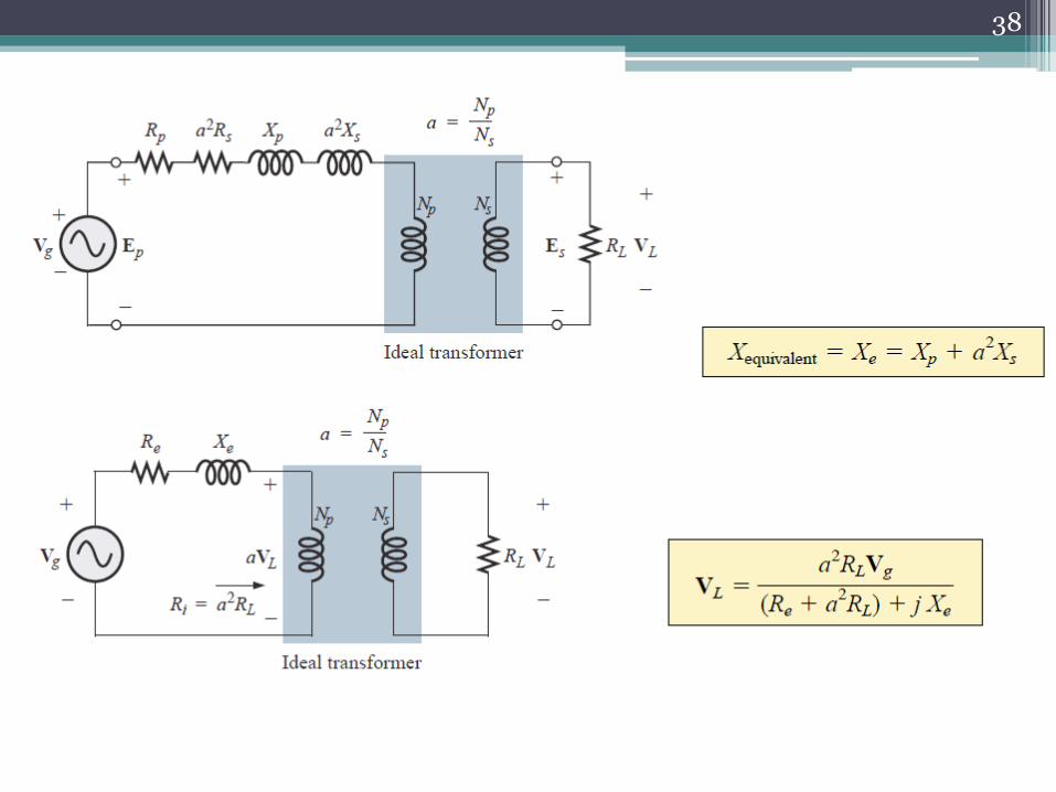
It is often convenient to assume that all of the resistance and reactance as being on one side of the transformer.

37
38

39

40
Maximum Efficiency: