esd5100 series - governors america
TRANSCRIPT

1 Governors America Corp. © 2021 Copyright All Rights ReservedESD5100 Series Speed Control Unit 2-2021-F2 PIB1000
ESD5100 SeriesSpeed Control Unit
3 SPECIFICATIONS
Performance
Isochronous Operation ±0.25 % or better
Speed Range /Governor 1 K - 7.5 K Hz Continuous
Speed Drift with Temperature ±0.5 % Typical
Idle Adjust CW MIN 1200 Hz Below set speed
Idle Adjust CCW MIN. 4100 Hz Below set speed
Droop Range 1 - 5 % Regulation
Droop Adj. MAX (K-L Jumpered) 875 Hz., ±75 Hz per 1.0 A change
Droop Adj. MIN (K-L Jumpered) 15 Hz., ±6 Hz per 1.0 A change
Speed Trim Range ±200 Hz
Remote Variable Speed Range 500 - 3.7 kHz
Terminal Sensitivity JLNP
115 Hz., ±15 Hz/V @ 5 K Impedance735 Hz., ±60 Hz/V @ 65 K Impedance148 Hz., ±10 Hz/V @ 1 M Impedance
10 V DC Supply @ 20 mA MAX
InPUT PoWerDC Supply 12 or 24 V DC Battery Systems
(Transient - Reverse Voltage Protected)
Polarity Negative Ground (case isolated)
Power Consumption 100 mA (No actuator current)
Speed Signal Range 0.5 – 50 V AC
Actuator Current Range 10 A Peak @ 77 ° F [25 °C]
Speed Signal Range 1.0 to 50.0 V AC
1 INTrODUCTION
The ESD5100 Series speed control unit is an all electronic device designed to control engine speed with fast and precise response to transient load changes. This closed loop control, when connected to a proportional electric actuator and supplied with a magnetic speed sensor signal, controls a wide variety of engines in isochronous or droop mode. It is designed for high reliability and is hard potted to withstand the engine environment.
The ESD5131 is a derivation of the standard GAC ESD5111 Speed Control Unit. All specifications, installation procedures, and adjustments, except those noted are iden-tical. The ESD5131 comes with DIP switches which allow for the selection of the Lead Circuit and Soft Coupling features. The ESD5111 comes with the Lead circuit already enabled via a jumper across posts E7 and E6.
CONTrOllEr mODElS2ParT nUmBer feaTUreS
ESD5111 Multi VDC / Standard Unit
ESD5111T Multi VDC / Temperature Compensated
ESD5119 Multi VDC / Cummins EFC Reverse Acting (Normally open)
ESD5120 Multi VDC / Light-Force (Low Current Optimized) Cummins EFC Forward Acting (Normally Closed)
ESD5131 Multi VDC / Switchable Soft Coupling and Lead Circuit
ESD5150 Multi VDC / Cummins EFC Forward Acting\ 4 - 20 mA Output
ESD5159 Multi VDC / Expanded Frequency Range to 14 kHz
ESD5160 Multi VDC / Cummins EFC Reverse Acting for Fire Pump Applications / Expanded Frequency Range to 10.5 kHz
PHYSIcaLDimensions See Section 4, INSTALLATION
Weight 1.2 lbf [0.545 kgf]
Mounting Any Position, vertical preferred
reLIaBILITYVibration 1 G, 20 - 100 Hz
Testing 100 % Functionally Tested
envIronmenTaL
Ambient Temperature -40° to +185 °F [-40° to +85 °C]
Relative Humidity up to 95 %
All Surface Finishes Fungus proof and corrosion resistant
RoHS Regulation Compliant
comPLIance / STandardSAgency CE Requirements
2 Governors America Corp. © 2021 Copyright All Rights ReservedESD5100 Series Speed Control Unit 2-2021-F2 PIB1000
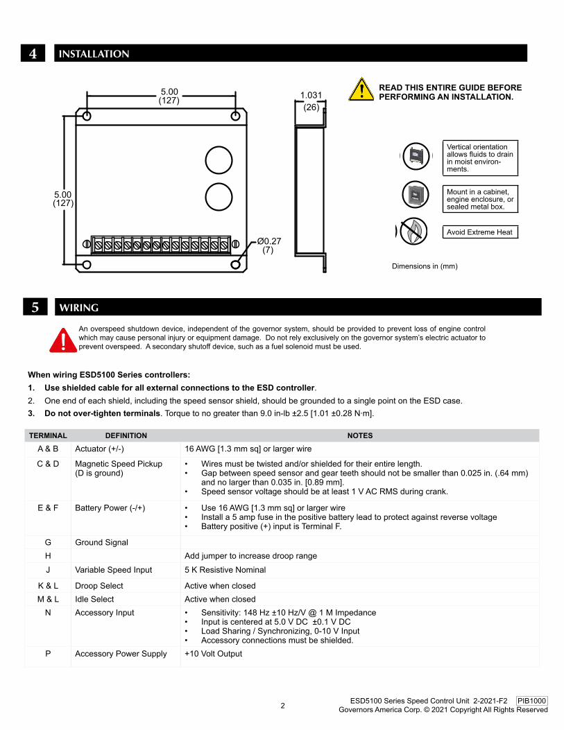
4 INSTAllATION
Mount in a cabinet, engine enclosure, or sealed metal box.
Vertical orientation allows fluids to drain in moist environ-ments.
Dimensions in (mm)
Avoid Extreme Heat
5.00(127)
Ø0.27(7)
1.031(26)
5.00(127)
An overspeed shutdown device, independent of the governor system, should be provided to prevent loss of engine control which may cause personal injury or equipment damage. Do not rely exclusively on the governor system’s electric actuator to prevent overspeed. A secondary shutoff device, such as a fuel solenoid must be used.
WIrING5
TermInaL defInITIon noTeS
A & B Actuator (+/-) 16 AWG [1.3 mm sq] or larger wire
C & D Magnetic Speed Pickup (D is ground)
• Wires must be twisted and/or shielded for their entire length.• Gap between speed sensor and gear teeth should not be smaller than 0.025 in. (.64 mm)
and no larger than 0.035 in. [0.89 mm].• Speed sensor voltage should be at least 1 V AC RMS during crank.
E & F Battery Power (-/+) • Use 16 AWG [1.3 mm sq] or larger wire• Install a 5 amp fuse in the positive battery lead to protect against reverse voltage• Battery positive (+) input is Terminal F.
G Ground SignalH Add jumper to increase droop rangeJ Variable Speed Input 5 K Resistive Nominal
K & L Droop Select Active when closedM & L Idle Select Active when closed
N Accessory Input • Sensitivity: 148 Hz ±10 Hz/V @ 1 M Impedance• Input is centered at 5.0 V DC ±0.1 V DC• Load Sharing / Synchronizing, 0-10 V Input• Accessory connections must be shielded.
P Accessory Power Supply +10 Volt Output
read THIS enTIre GUIde Before PerformInG an InSTaLLaTIon.
When wiring eSd5100 Series controllers:1. Use shielded cable for all external connections to the eSd controller.2. One end of each shield, including the speed sensor shield, should be grounded to a single point on the ESD case.3. do not over-tighten terminals. Torque to no greater than 9.0 in-lb ±2.5 [1.01 ±0.28 N∙m].

3 Governors America Corp. © 2021 Copyright All Rights ReservedESD5100 Series Speed Control Unit 2-2021-F2 PIB1000
WIrING - CONTINUED5
ESD5131 SWITCHES ONLy

4 Governors America Corp. © 2021 Copyright All Rights ReservedESD5100 Series Speed Control Unit 2-2021-F2 PIB1000
6
7
ADjUSTmENTS
Before STarTInG THe enGIne
STarT enGIne
The speed control unit governed speed setting is factory set at approximately engine idle speed. (1000 Hz., Speed sensor signal or 600 RPM)
Crank the engine with DC power applied to the governor system. The actuator will energize to the maximum fuel position until the en-gine starts. The governor system should control the engine at a low idle speed. If the engine is unstable after starting, refer to Section ADJUSTING FOR STABILITy.
Governor SPeed SeTTInG
Adjust Gain, Stability, and Trim to the middle position before starting the engine.
GaIn Middle Position
STaBILITY Middle Position
SPeed TrIm conTroL Middle Position
The governed speed set point is increased by clockwise rotation of the SPEED adjustment control. SPEED adjustment is a 25 turn potentiometer.
STABILITY
SPEEDGAIN
E7E6
adjUSTInG for STaBILITY
Once the engine is running at operating speed and at no load, the following governor performance adjustments can be made to increase engine stability.
STABILITY
SPEEDGAIN
E7E6
Normally, adjustments made at no load achieve satisfactory performance. If further performance improvements are required, refer to Section 8 SySTEM TROUBLESHOOTING.
STaBILITY adjUSTmenTParameTer ProcedUre
GAIN 1. Rotate the GAIN adjustment clockwise until instability develops.2. Gradually move the adjustment counterclockwise until stability returns.3. Move the adjustment one division further counterclockwise to insure stable performance (270° potentiome-
ter). 4. If instability persists, adjust the next parameter.
STABILITy Follow the same adjustment procedure, steps 1 - 3, as the GAIN parameter.
noTe
IdLe SPeed SeTTInG
ADDITIONAl FEATUrES & OPTIONAl WIrING
After the governor speed setting had been adjusted, place the optional external selector switch in the IDLE position. The idle speed set point is increased by the clockwise rotation of the IDLE adjustment control. When the engine is at idle speed, the speed control unit applies droop to the governor system to insure stable operation.
E1 E2 E3
IDLE
DROOP

5 Governors America Corp. © 2021 Copyright All Rights ReservedESD5100 Series Speed Control Unit 2-2021-F2 PIB1000
Droop is typically used when paralleling engine driven generators. When in droop operation, the engine speed will decrease as engine load increases. The percentage of droop is based on the actuator current change from no engine load to full load.
1. Place the optional external selector switch in the DROOP position. DROOP is increased by clockwise rotation of the DROOP adjust-ment control.
2. After the droop level has been adjusted, the rated engine speed setting may need to be reset. Check the engines speed and adjust that speed setting accordingly.
Though a wide range of droop is available with the internal control, droop level requirements of 10% are unusual. If droop levels experienced are higher or lower than those required, contact GAC for assistance.
SPeed drooP oPeraTIon
noTe
(Cut to disable)
All ESD5100 Series speed controllers come with the Lead Circuit enabled. Cut the jumper between posts E6 and E7 to disable. ESD5131 has a switch to disable the Lead Circuit.
SeLecTaBLe Lead cIrcUIT & SofT coUPLInG eSd5131 onLY
Switch 1(C1) controls the Lead Circuit found in the ESD5131. The nor-mal position is ON. Move the switch to the “OFF” position if there is fast instability in the system.
Switch 2(C2) controls an additional circuit added in the ESD5131 de-signed to eliminate fast erratic governor behavior usually caused by very soft or worn couplings in the drive train between the engine and generator. The normal position is OFF. Move to the ON position if fast erratic engine behavior due to a soft coupling is experienced.
LEAD CIRCUITJUMPER
STABILITY
SPEED
GAIN
E7 E6 OFF
ON 2SOFT COUPLING
1 OFF
ONLEAD CIRCUIT
1 21 2
ESD5131ESD5111
noTe
LEAD CIRCUITJUMPER
STABILITY
SPEED
GAIN
E7 E6 OFF
ON 2SOFT COUPLING
1 OFF
ONLEAD CIRCUIT
1 21 2
ESD5131ESD5111
Speed adjustment Is a 25 Turn Potentiometer
7 ADDITIONAl FEATUrES & OPTIONAl WIrING - CONTINUED
acceSSorY SUPPLY
The +10 volt regulated supply, Terminal P, can be utilized to provide power to GAC governor system accessories. Up to 20 mA of current can be drawn from this supply. Ground reference is Terminal G.
A short circuit on this terminal will damage the speed control unit.
When an accessory is connected to Terminal N, the speed will decrease and the speed adjustment must be reset.
When operating in the upper end of the control unit frequency range, a jumper wire or frequency trim control may be required between Terminals G and J. This increases the frequency range of the speed control to over 7000 Hz.
If the auto synchronizer is used alone, not in conjunction with a load sharing module, con-nect a 3 m Ω resister between Terminals N and P. This is required to match the voltage levels between the speed control unit and the synchronizer.
acceSSorY InPUT
noTe
The Auxiliary Terminal N accepts signals from load sharing units, auto synchronizers and other governor system accessories, GAC accessories are directly connected to this terminal.
noTe

6 Governors America Corp. © 2021 Copyright All Rights ReservedESD5100 Series Speed Control Unit 2-2021-F2 PIB1000
WIde ranGe remoTe SPeed oPeraTIon
A single remote speed adjustment potentiometer can be used to adjust the engine speed continuously over a specific speed range.
Select the desired speed range and corresponding potentiometer value (TABLE 1). If the exact range cannot be found, select the next higher range potentiometer.
To maintain engine stability at the minimum speed setting, a small amount of droop can be added using the DROOP adjustment. At the maximum speed setting the governor performance will be near isochronous, regardless of the droop adjustment setting.
An additional fixed resistor may be placed across the potentiometer to obtain the exact desired range. Connect the speed range potentiometer as shown below. Contact GAC for assistance if difficulty is experienced in obtaining the desired vari-able speed governing performance.
noTe
SPeed freQUencY ranGe PoTenTIomeTer vaLUe900 Hz 1 K
2400 Hz 5 K
3000 Hz 10 K
3500 Hz 25 K
3700 Hz 50 K
TaBLe 1conversion formulas
HertzMAG PICKUP = (RPM x #Teeth)
60secRPM =
(HertzMAG PICKUP x 60sec)
#Teeth
Wide range remote vari-able Speed Pot. Wiring Per
Table 1
Trim Pot. Wiring: 5 K Pot. for +/- 200 Hz range of
adjustment
8 SySTEm TrOUblEShOOTING
InSUffIcIenT maGneTIc SPeed SIGnaL
A strong magnetic speed sensor signal will eliminate the possibility of missed or extra pulses. The speed control unit will govern well with 1.0 V AC speed sensor signal. A speed sensor signal of 3 V AC or greater at governed speed is recommended. Measurement of the signal is made at Terminals C and D.
The amplitude of the speed sensor signal can be raised by reducing the gap between the speed sensor tip and the engine ring gear. The gap should not be any smaller than 0.025 in [0.64 mm]. When the engine is stopped, back the speed sensor out by 3/4 turn after touching the ring gear tooth to achieve a satisfactory air gap.
SYSTem InoPeraTIve
If the engine governing system does not function, the fault may be determined by performing the voltage tests described in Steps 1 through 4. Positive (+) and negative (-) refer to meter polarity. Should normal values be indicated during troubleshooting steps, and then the fault may be with the actuator or the wiring to the actuator. Tests are performed with battery power on and the engine off, except where noted. See your actuator publication for testing and troubleshooting of the actuator.
7 ADDITIONAl FEATUrES & OPTIONAl WIrING - CONTINUED

7 Governors America Corp. © 2021 Copyright All Rights ReservedESD5100 Series Speed Control Unit 2-2021-F2 PIB1000
8 SySTEm TrOUblEShOOTING - CONTINUED
STeP WIreS normaL readInG ProBaBLe caUSe of aBnormaL readInG
1 F(+) & E(-)
Battery Supply Voltage (12 or 24 V DC)
1. DC battery power not connected. Check for blown fuse.2. Low battery voltage.3. Wiring error.
2 C(+) & D(-)
1.0 V AC minimum while crank-ing
1. Gap between speed sensor and gear teeth too great. Check Gap.2. Improper or defective wiring to the speed sensor. Resistance between
Terminals D and C should be 160 to 1200 Ω. See specific mag pickup data for resistance.
3. Defective speed sensor.3 P(+) &
G(-)10 V DC, Internal Supply 1. Short on Terminal P.
2. Defective speed control unit.4 F(+) &
A(-)1.0 - 2.0 V DC while cranking 1. SPEED parameter set too low.
2. Short/open in actuator wiring.3. Defective speed control.4. Defective actuator, see 5. Actuator Troubleshooting.
InSTaBILITY
SYmPTom cHecK ProBaBLe caUSe
Fast Periodic The engine seems to jitter with a 3Hz or faster irregulari-ty of speed.
1. Turn off other electrical equipment that may be causing interference.2. Readjust the GAIN and STABILITy for optimum control.3. Remove the E6 to E7 jumper (This reduces sensitivity to high frequencies).4. If system is still unstable, remove the E1 to E2 jumper and readjust GAIN and STABILITy.
Slow Peri-odic
An irregularity of speed below
3Hz.
1. Readjust the GAIN and STABILITy 2. Set DIP switches 1 and 2 to ON in the following order: First SW1, Second SW23. Check fuel system linkage during engine operation for:
a. bindingb. high frictionc. poor linkage
4. Adjust the DEAD TIME COMPENSATION by adding a capacitor from post E2 to E3 (nega-tive on E2). Start with 10 mfds and increase until instability is eliminated.
Non-Periodic Erratic Engine Behavior
1. Increasing the GAIN should reduce the instability but not totally correct it. 2. If this is the case, there is most likely a problem with the engine itself. Check for:
a. engine mis-firingsb. erratic fuel systemc. load changes on the generator set voltage regulator.
4. If throttle is slightly erratic, but performance is fast, then remove the jumper from E6 to E7.
Instability in a closed loop speed control system can be categorized into two general types. PERIODIC appears to be sinusoidal and at a regular rate. NON-PERIODIC is a random wandering or an occasional deviation from a steady state band for no apparent reason.

8 Governors America Corp. © 2021 Copyright All Rights ReservedESD5100 Series Speed Control Unit 2-2021-F2 PIB1000
UnSaTISfacTorY Performance
SYmPTom cHecK ProBaBLe caUSe
Engine Overspeeds
Do Not Crank. Apply DC power to the governor system.
After the actuator goes to full fuel, disconnect the speed sensor at Terminal C & D. If the actuator is still at full fuel-speed then the speed control unit is defective.
Manually hold the engine at the desired running speed. Measure the DC voltage between Termi-nals A(-) & F(+) on the speed control unit.
If the voltage reading is 1.0 to 2.0 V DC:a. SPEED adjustment is set above desired speedb. Defective speed control unit
If voltage reading is above 2.0 V DC then check for:a. actuator bindingb. linkage binding
Set point of overspeed shutdown device set too low.
If the voltage reading is below 1.0 V DC it is a defective speed control unitEngine Shuts down
Overspeed Shuts Down Engine After Running Speed is Reached
• Speed adjustment set too high.• OVERSPEED set to close to running speed.• Actuator or linkage binding.• Speed control unit defective.
Overspeed Shuts Down Engine Before Running Speed is Reached
Check impedance between Terminals C & D. Should be 160 to 1200 Ohms
OVERSPEED set too low. Adjust 5 - 6 turns CW.
Erroneous speed sensor signal. Check wiring.
Actuator does not energize fully
Measure the voltage at the bat-tery while cranking.
If voltage is less than 7 V DC for a 12 V DC system, or 14 V DC for a 24 V DC system, check or replace the battery.
Momentarily connect Terminals A and F. The actuator should move to the full fuel position.
Actuator or battery wiring in error
Actuator or linkage binding
Defective actuator
Fuse opens. Check for short in actuator or harness.Engine remains below desired governed speed
Measure the actuator output, Terminals A & B, while running under governor control.
If voltage measurement is within 2 V DC of the battery supply voltage level, then fuel control is restricted from reaching full fuel position, possibly due to mechanical governor, carburetor spring, or linkage interference.
SPEED parameter set too low.
8 SySTEm TrOUblEShOOTING - CONTINUED