escuela tÉcnica superior de ingenierÍa (icai) master in
TRANSCRIPT
ESCUELA TÉCNICA SUPERIOR DE INGENIERÍA (ICAI)
MASTER IN INDUSTRIAL ENGINEERING
ANALYSIS OF THE RISKS
OF THE ECOCAR 3 PROJECT
Author:
Jorge Nieto Gavilán
Director:
Dr. Patrick N. Currier
Madrid July 2016


ESCUELA TÉCNICA SUPERIOR DE INGENIERÍA (ICAI)
MASTER IN INDUSTRIAL ENGINEERING
ANALYSIS OF THE RISKS
OF THE ECOCAR 3 PROJECT
Author:
Jorge Nieto Gavilán
Director:
Dr. Patrick N. Currier
Madrid July 2016


ANALYSIS OF THE RISKS OF THE ECOCAR 3 PROJECT Abstract
________________________________________________________________________
JORGE NIETO JULY 2016
ANÁLISIS DE LOS RIESGOS DEL PROYECTO ECOCAR 3
Autor: Nieto Gavilán, Jorge.
Director: Currier, Patrick.
Entidad Colaboradora: Embry-Riddle Aeronautical University.
RESUMEN DEL PROYECTO
Introducción
Este TFM se ha desarrollado como miembro del equipo de ERAU para EcoCAR 3
durante el segundo año de competición. El propósito es estudiar los riesgos de los
distintos diseños del equipo, analizando su peligro potencial y usando esa evaluación para
proponer medidas preventivas y correctoras. El estudio se ha llevado a cabo en su
totalidad dentro del grupo de seguridad, una sección del equipo. Por lo tanto, este TFM
presenta tanto el progreso del equipo durante este tiempo como el trabajo personal.
Existen varios objetivos diferentes en este TFM, siendo el análisis su parte central.
Sin embargo, lo más importante no es llevar a cabo el análisis, sino desarrollar un modelo
sólido y las herramientas necesarias para que otros estudiantes puedan terminar el análisis
en el futuro, ya que la competición dura un total de cuatro años.
El siguiente diagrama muestra el diseño del equipo al comienzo del TFM.
Figura r1: Diagrama de componentes y flujos de potencia del esquema LEA Parallel-Series-A.
Como se puede observar, el modelo tiene dos motores eléctricos junto con el motor
de gasolina, y dos embragues distintos que permiten que los motores trabajen tanto en

ANALYSIS OF THE RISKS OF THE ECOCAR 3 PROJECT Abstract
________________________________________________________________________
JORGE NIETO JULY 2016
serie como en paralelo. Esta configuración permite al coche tener cuatro modos de
funcionamiento diferentes, en función del flujo de potencia que opera el vehículo.
Metodología
Las principales tareas del TFM están listadas en orden a continuación:
1. Revisión del trabajo realizado por el equipo durante el primer año.
2. Investigar sobre vehículos híbridos, sistemas de seguridad y técnicas de análisis.
3. Elegir algunas de esas técnicas y desarrollar una metodología consistente para el
proceso de análisis.
4. Analizar algunos de los principales subsistemas del coche con el método HAZOP.
5. Desarrollar los primeros requisitos como referencia para el futuro y explicar los
resultados y conclusiones del trabajo realizado.
Para el proceso de análisis se han propuesto tres métodos diferentes, uno para cada
enfoque tradicional (deductivo, inductivo y exploratorio). Estos métodos son los análisis
FTA, DFMEA y HAZOP.
Un FTA es una herramienta de análisis deductivo usada para estudiar un evento
específico no deseado, como un fallo en los frenos o en el motor. Es un modelo gráfico
que representa las múltiples combinaciones de fallos del equipamiento y errores humanos
que pueden resultar en el fallo principal del sistema que se está considerando [r1]. La
identificación del riesgo se deriva de identificar primero los peligros, en lo que se conoce
como enfoque descendente.
El DFMEA es la aplicación específica del método FMEA al diseño de un producto o
servicio, que se centra en cómo éste podría fallar [r2]. El método FMEA se diseña para
identificar y entender completamente los modos potenciales de fallo y sus causas y
efectos, para evaluar los riesgos y proponer acciones correctoras [r3].
Este método es un análisis ingenieril realizado por un grupo multidisciplinar de
expertos y el proceso de análisis se puede considerar como un proceso lógico.
El estudio HAZOP (peligro y operatividad, por sus siglas en inglés) es un examen
estructurado y sistemático de un proceso planeado o existente para identificar y evaluar
problemas que pueden ser un riesgo para el personal o los equipos [r4].
Un HAZOP es una revisión detallada y sistemática de un proceso realizada por un
equipo, preferentemente guiado por una persona con experiencia e independiente. Usa un
enfoque de lluvia de ideas con una serie de palabras guía. Los principales elementos a
considerar son la intención, derivación, causas, consecuencias, salvaguardias y acciones
correctivas.
La siguiente figura resume el razonamiento que subyace en cada uno de estos
métodos de análisis.

ANALYSIS OF THE RISKS OF THE ECOCAR 3 PROJECT Abstract
________________________________________________________________________
JORGE NIETO JULY 2016
Figure r2: Resumen del razonamiento en cada una de las técnicas presentadas.
Debido a la importancia de la organización del trabajo, el equipo se dividió de forma
que cada persona fuera responsable de una tarea, incluyendo estos análisis. Además, el
análisis ha sido llevado a cabo siguiendo un esquema dado con varias etapas [r5].
Resultados
El análisis HAZOP se puede considerar como la principal tarea de este TFM. Los
resultados de las funciones con mayor riesgo según el análisis se resumen a continuación.
Subsistema Función Evaluación del
riesgo Medidas de atenuación
ESS Impermeabilidad Alto (C) - Detectar y aislar el líquido. - Requisitos de aislamiento.
ESS Soporte del
equipaje Medio (B)
- Pegatinas de aviso con las cargas
admisibles visibles para el usuario.
- Garantizar que la cobertura de la batería
aguanta una carga axial de 130 kg.
ESS Soporte del módulo Bajo (A) - Factor de seguridad de 1.5 en la estructura.
ESS Seguridad del
usuario Bajo (A)
- Cierre apropiado de las partes peligrosas. - Elaborar procedimientos de mantenimiento
y acceso seguros.
Combustible Prevención contra
incendios Medio (B)
- Asegurar un sellado apropiado alrededor
de cualquier apertura o conector.
- Instalar sistema de extinción.
Combustible Resistencia a la
perforación Bajo (A)
- Medir dicha Resistencia. - Sellar el sistema correctamente.
Combustible Montaje Bajo (A)
- Diseñar conforme a los requisitos (8g para
cargas verticales estáticas y de 20 g para las
longitudinales y laterales, además de un
factor de seguridad de 1.5).
Térmico Refrigeración del
motor/transmisión Bajo (A) - Instalar sensores de temperatura.
Térmico Almacenamiento
refrigerante Bajo (A)
- Instalar anti-fugas en el depósito. - Aislamiento apropiado del sistema.
Tabla r1: Principales resultados del análisis

ANALYSIS OF THE RISKS OF THE ECOCAR 3 PROJECT Abstract
________________________________________________________________________
JORGE NIETO JULY 2016
Como puede verse, los mayores niveles de riesgo corresponden a la impermeabilidad
de la batería, con un nivel C, seguido por el soporte del equipaje de la batería y el sistema
de prevención contra incendios del combustible (con un nivel B en ambos casos).
Con respecto a la competición, los resultados del grupo de sistemas de seguridad no
podrían haber sido mejores, ya que el equipo resultó campeón de la competición.
Conclusiones
Conclusiones del análisis
A partir de los resultados existentes, la primera conclusión relevante es que el grado
de riesgo obtenido en la mayoría de los casos es bastante bajo de acuerdo con los
estándares. Sin embargo, en la mayoría de los casos esto no se debe a una baja
peligrosidad de los eventos indeseados, sino al impacto de los otros parámetros que se
usan para evaluar un riesgo, como la probabilidad del evento y su controlabilidad.
Sea como sea, la mayor parte de los eventos analizados tienen un nivel de riesgo bajo
(A) o muy bajo (QM), como se puede observar en la siguiente tabla.
Evaluación QM A B C D Por determinar
Porcentaje 38,9% 44,4% 11,1% 5,6% 0,0% 5,6%
Tabla r2: Frecuencia de cada nivel de riesgo de acuerdo con el criterio ASIL.
Además, los resultados pueden analizarse por subsistemas para determinar cuál es el
más peligroso usando una escala numérica en la cual se asigna un valor para cada uno de
los niveles de riesgo, desde 1 hasta 5. De este modo los valores medios son:
Subsistema Riesgo medio
ESS 2,44
Aceite 1
Combustible 1,5
Térmico 1,43
Total 1,94
Table r3: Riesgo medio de cada subsistema
Este análisis concluye que el riesgo medio es bastante bajo, con un nivel de 1.94. El
sistema con mayor nivel de riesgo es la batería (ESS) y el del menor es el sistema de
aceite.
ANALYSIS OF THE RISKS OF THE ECOCAR 3 PROJECT Abstract
________________________________________________________________________
JORGE NIETO JULY 2016
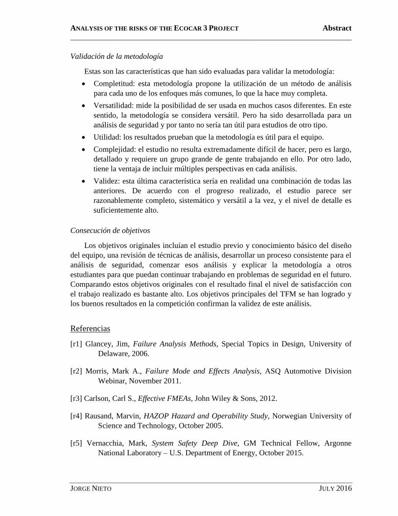
Validación de la metodología
Estas son las características que han sido evaluadas para validar la metodología:
Completitud: esta metodología propone la utilización de un método de análisis
para cada uno de los enfoques más comunes, lo que la hace muy completa.
Versatilidad: mide la posibilidad de ser usada en muchos casos diferentes. En este
sentido, la metodología se considera versátil. Pero ha sido desarrollada para un
análisis de seguridad y por tanto no sería tan útil para estudios de otro tipo.
Utilidad: los resultados prueban que la metodología es útil para el equipo.
Complejidad: el estudio no resulta extremadamente difícil de hacer, pero es largo,
detallado y requiere un grupo grande de gente trabajando en ello. Por otro lado,
tiene la ventaja de incluir múltiples perspectivas en cada análisis.
Validez: esta última característica sería en realidad una combinación de todas las
anteriores. De acuerdo con el progreso realizado, el estudio parece ser
razonablemente completo, sistemático y versátil a la vez, y el nivel de detalle es
suficientemente alto.
Consecución de objetivos
Los objetivos originales incluían el estudio previo y conocimiento básico del diseño
del equipo, una revisión de técnicas de análisis, desarrollar un proceso consistente para el
análisis de seguridad, comenzar esos análisis y explicar la metodología a otros
estudiantes para que puedan continuar trabajando en problemas de seguridad en el futuro.
Comparando estos objetivos originales con el resultado final el nivel de satisfacción con
el trabajo realizado es bastante alto. Los objetivos principales del TFM se han logrado y
los buenos resultados en la competición confirman la validez de este análisis.
Referencias
[r1] Glancey, Jim, Failure Analysis Methods, Special Topics in Design, University of
Delaware, 2006.
[r2] Morris, Mark A., Failure Mode and Effects Analysis, ASQ Automotive Division
Webinar, November 2011.
[r3] Carlson, Carl S., Effective FMEAs, John Wiley & Sons, 2012.
[r4] Rausand, Marvin, HAZOP Hazard and Operability Study, Norwegian University of
Science and Technology, October 2005.
[r5] Vernacchia, Mark, System Safety Deep Dive, GM Technical Fellow, Argonne
National Laboratory – U.S. Department of Energy, October 2015.

ANALYSIS OF THE RISKS OF THE ECOCAR 3 PROJECT Abstract
________________________________________________________________________
JORGE NIETO JULY 2016
ANALYSIS OF THE RISKS OF THE ECOCAR 3 PROJECT
ABSTRACT
Introduction
This thesis has been developed as a member of the ERAU team for EcoCAR 3,
during the second year of the competition. The target is to study the risks of the different
designs of the team, analyzing its potential hazard and use that evaluation to propose
preventive and corrective measures. The whole study has been carried out within the
system safety group, a section of the team. Therefore, this thesis presents both the
progress of the group during this time and the personal work and study for the thesis.
There are several different goals for this thesis, being the analysis the core of it.
However, the most important thing is not to carry out a whole analysis, but to develop a
solid model and the proper tools, so that other students can finish the analysis in the
future, since the competition lasts four years in total.
A diagram of the design of the team at the beginning of this thesis is shown below.
Figure a1: LEA Parallel-Series-A Component Diagram and Power Flow Diagram.
As it is can be seen, this model has two electric motors together with the diesel
engine, and two different clutches that allow the motors work in both parallel and series
modes. This configuration allows the car to have four different modes of operation,
depending on how the power flows to run the vehicle.
Methodology
The main tasks of this thesis are listed in order below:

ANALYSIS OF THE RISKS OF THE ECOCAR 3 PROJECT Abstract
________________________________________________________________________
JORGE NIETO JULY 2016
1. Review of the work done by the team in the first year.
2. Doing some research on hybrid vehicles, systems safety and analysis techniques.
3. Choosing some of the techniques and developing a consistent methodology for
the process of analysis.
4. Analyzing some of the main subsystems of the car using the HAZOP method.
5. Developing the first requirements as a reference for the future and explaining the
results and conclusions of the work done.
For the process of analysis, three different methods have been proposed, one for each
traditional approach (deductive, inductive and exploratory). These methods are the FTA,
the DFMEA and the HAZOP analysis.
An FTA (Fault Tree Analysis) is a deductive analytical tool used to study a specific
undesired event, such as a failure in the breaks or the engine. It is a graphical model that
displays the various combinations of equipment failures and human errors that can result
in the main system failure of interest [a1]. The identification of risk is derived by first
identifying faults/hazards, so that is called a top down approach.
The DFMEA (Design Failure Mode and Effect Analysis) is the application of the
FMEA method specifically to product/service design, which focuses on how product
design might fail [a2]. The FMEA method is designed to identify and fully understand
potential failure modes and their causes and effects, to assess the risks and propose
corrective actions [a3].
This method is an engineering analysis done by a cross-functional team of experts
and the process of analysis can be considered as a logical flow.
HAZard and OPerability (HAZOP) study is a structured and systematic examination
of a planned or existing process or operation in order to identify and evaluate problems
that may represent risks to personnel or equipment [a4].
A HAZOP is a systematic and detailed review of a process by a team, preferably led
by an experienced and independent person. It uses a brainstorming approach with a series
of guide words. The main elements under consideration for the HAZOP are intention,
deviation, causes, consequences, safeguards and corrective action.
The figure below summarized the reasoning behind these three methods of analysis.
Figure a2: Summary of the reasoning of the presented techniques.
ANALYSIS OF THE RISKS OF THE ECOCAR 3 PROJECT Abstract
________________________________________________________________________
JORGE NIETO JULY 2016
Taking into account the importance of following an organized process in the
evaluation of the risks of the EcoCAR 3 Project, the safety team was divided so that each
person was in charge of one task, including these analyses. Furthermore, the analysis has
been carried out following a given scheme with several steps [a5].
Results
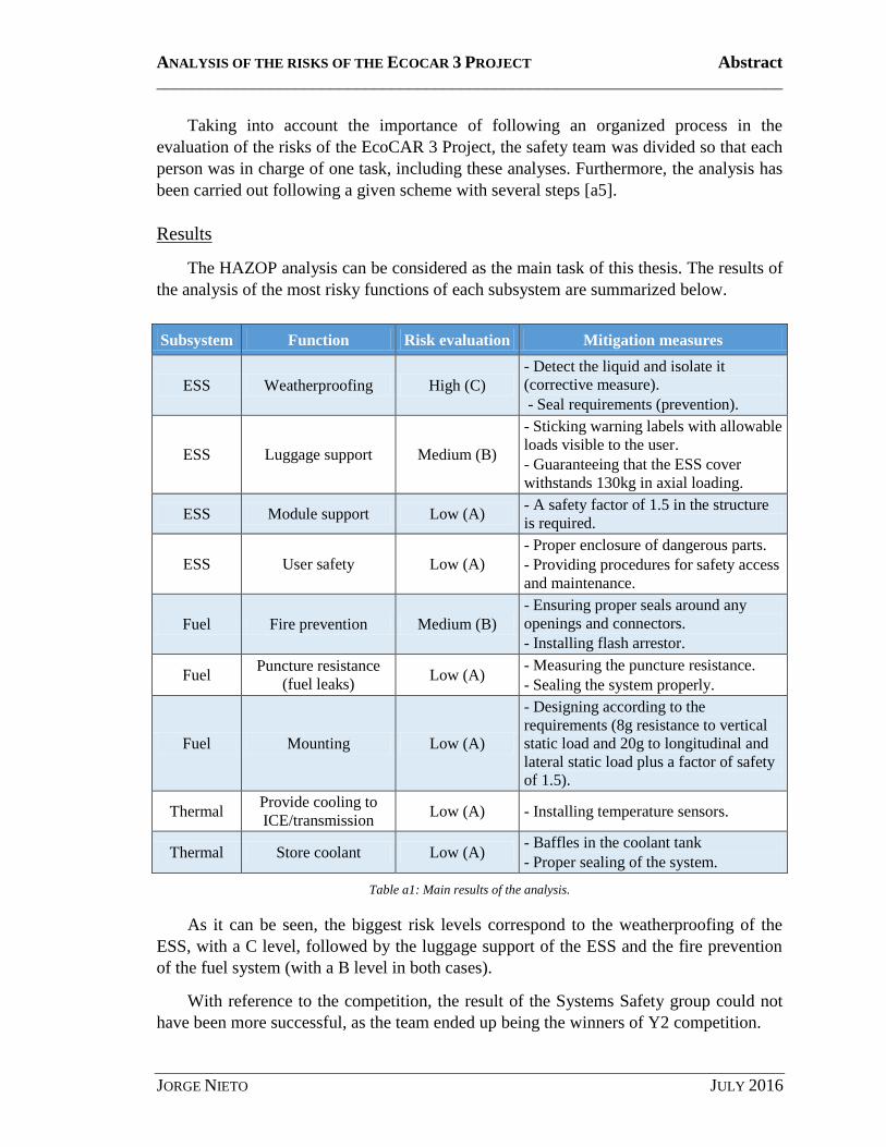
The HAZOP analysis can be considered as the main task of this thesis. The results of
the analysis of the most risky functions of each subsystem are summarized below.
Subsystem Function Risk evaluation Mitigation measures
ESS Weatherproofing High (C) - Detect the liquid and isolate it
(corrective measure).
- Seal requirements (prevention).
ESS Luggage support Medium (B)
- Sticking warning labels with allowable
loads visible to the user. - Guaranteeing that the ESS cover
withstands 130kg in axial loading.
ESS Module support Low (A) - A safety factor of 1.5 in the structure
is required.
ESS User safety Low (A) - Proper enclosure of dangerous parts. - Providing procedures for safety access
and maintenance.
Fuel Fire prevention Medium (B) - Ensuring proper seals around any
openings and connectors. - Installing flash arrestor.
Fuel Puncture resistance
(fuel leaks) Low (A)
- Measuring the puncture resistance. - Sealing the system properly.
Fuel Mounting Low (A)
- Designing according to the
requirements (8g resistance to vertical
static load and 20g to longitudinal and
lateral static load plus a factor of safety
of 1.5).
Thermal Provide cooling to
ICE/transmission Low (A) - Installing temperature sensors.
Thermal Store coolant Low (A) - Baffles in the coolant tank - Proper sealing of the system.
Table a1: Main results of the analysis.
As it can be seen, the biggest risk levels correspond to the weatherproofing of the
ESS, with a C level, followed by the luggage support of the ESS and the fire prevention
of the fuel system (with a B level in both cases).
With reference to the competition, the result of the Systems Safety group could not
have been more successful, as the team ended up being the winners of Y2 competition.

ANALYSIS OF THE RISKS OF THE ECOCAR 3 PROJECT Abstract
________________________________________________________________________
JORGE NIETO JULY 2016
Conclusions
Conclusions of the analysis
From the existing results, the first relevant conclusion that is observed is that the
actual degree of riskiness obtained in most cases in quite low according to the standards.
However, in most cases this is not because the undesired events are not dangerous, but
because of the other parameters that are used to assess a risk, such as likelihood of the
event and its controllability.
Anyway, most of the events that have been analyzed have a level of risk which is
low (A) or very low (QM, e.g. quality management), as it can be seen in the table below.
Risk evaluation QM A B C D To be determined
Percentage 38,9% 44,4% 11,1% 5,6% 0,0% 5,6%
Table a2: Frequency of each level of riskiness according to the ASIL standard.
Furthermore, the results can be analyzed by subsystems to determine which is the
most dangerous one is using a numerical scale, in which each of the levels of riskiness
has been given a value from 1 to 5. Thus, the average values are:
Subsystem Average riskiness
ESS 2,44
Oil 1
Fuel 1,5
Thermal 1,43
Total 1,94
Table a3: Average riskiness of every subsystem.
This analysis concludes that the average riskiness of the four subsystems that have
been analyzed is low, with an average value of 1.94. The most risky subsystem is the
ESS, with an average value of 2.44 and the less risky is the oil system, with a value of 1.
Methodology validation
These are the features that have been evaluated in order to validate the methodology:
Completeness: this methodology proposes the use of one method of analysis for
each of the most common approaches, which makes it very complete.
Versatility: it measures the possibility of using it for many different cases. In this
sense, the methodology is considered to be versatile. But it has been developed for
a safety analysis and thus it would not be so useful in other kinds of studies.

ANALYSIS OF THE RISKS OF THE ECOCAR 3 PROJECT Abstract
________________________________________________________________________
JORGE NIETO JULY 2016
Usefulness: the results prove that the methodology is useful for the team.
Complexity: the study is not extremely difficult to be done, but it is long, detailed
and requires a group of people working on it. On the other hand, it has the
advantage of having multiple perspectives in each analysis.
Validity: this last feature would be indeed a combination of all the others.
According to the progress done, the study seems to be reasonably complete,
systematic and versatile at the same time, and it has enough level of detail.
Attainment of objectives
The original objectives included the previous study and basic knowledge of the
design of the team, a review of the analysis techniques, developing a consistent process
for the safety analysis, starting those analyses and explaining the methodology to other
students so that they can continue working on safety issues in the future. Comparing
these original objectives with the final results, the level of satisfaction with the work done
is quite high. The main objectives of the thesis have been attained and the good results in
the competition confirm the validity of this safety evaluation.
References
[a1] Glancey, Jim, Failure Analysis Methods, Special Topics in Design, University of
Delaware, 2006.
[a2] Morris, Mark A., Failure Mode and Effects Analysis, ASQ Automotive Division
Webinar, November 2011.
[a3] Carlson, Carl S., Effective FMEAs, John Wiley & Sons, 2012.
[a4] Rausand, Marvin, HAZOP Hazard and Operability Study, Norwegian University of
Science and Technology, October 2005.
[a5] Vernacchia, Mark, System Safety Deep Dive, GM Technical Fellow, Argonne
National Laboratory – U.S. Department of Energy, October 2015.

ANALYSIS OF THE RISKS OF THE ECOCAR 3 PROJECT Table of Contents
________________________________________________________________________
JORGE NIETO - I - JULY 2016
TABLE OF CONTENTS
Table of Contents ................................................................................................................. I
Table of Figures ................................................................................................................ IV
Table of Tables .................................................................................................................. V
Introduction ......................................................................................................................... 1
1. Summary .............................................................................................................. 1
2. Project objectives ................................................................................................. 3
3. Motivation ............................................................................................................ 4
4. Methodology ........................................................................................................ 5
5. Sources ................................................................................................................. 7
Status of the issue................................................................................................................ 8
1. Summary of the project ........................................................................................ 8
2. Competition rules ............................................................................................... 10
3. ERAU Team background ................................................................................... 11
3.1. Team structure ............................................................................................ 11
3.2. Previous status ............................................................................................ 12
Literature Review.............................................................................................................. 15
1. Introduction to systems safety ............................................................................ 15
2. Analysis techniques ............................................................................................ 16
2.1. Deductive (FTA) ......................................................................................... 17
2.2. Inductive (DFMEA) .................................................................................... 18
2.3. Exploratory (HAZOP) ................................................................................ 19
2.4. Descriptive analysis: observation ............................................................... 22
3. Hybrid Vehicles.................................................................................................. 23
3.1. Technical considerations ............................................................................. 23
3.2. Basic components ....................................................................................... 24
3.3. Degrees of Hybridization ............................................................................ 25
3.4. Architectures ............................................................................................... 27
Safety Evaluation .............................................................................................................. 31
1. Process diagram.................................................................................................. 31
2. Regulations ......................................................................................................... 35
ANALYSIS OF THE RISKS OF THE ECOCAR 3 PROJECT Table of Contents
________________________________________________________________________
JORGE NIETO - II - JULY 2016
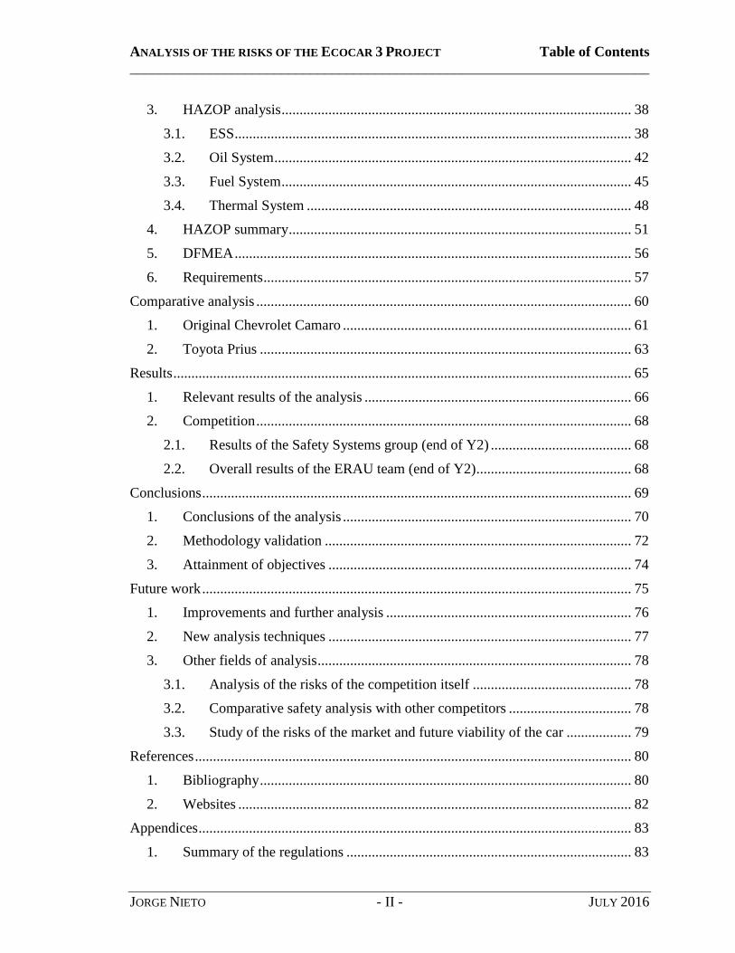
3. HAZOP analysis ................................................................................................. 38
3.1. ESS .............................................................................................................. 38
3.2. Oil System ................................................................................................... 42
3.3. Fuel System ................................................................................................. 45
3.4. Thermal System .......................................................................................... 48
4. HAZOP summary ............................................................................................... 51
5. DFMEA .............................................................................................................. 56
6. Requirements ...................................................................................................... 57
Comparative analysis ........................................................................................................ 60
1. Original Chevrolet Camaro ................................................................................ 61
2. Toyota Prius ....................................................................................................... 63
Results ............................................................................................................................... 65
1. Relevant results of the analysis .......................................................................... 66
2. Competition ........................................................................................................ 68
2.1. Results of the Safety Systems group (end of Y2) ....................................... 68
2.2. Overall results of the ERAU team (end of Y2) ........................................... 68
Conclusions ....................................................................................................................... 69
1. Conclusions of the analysis ................................................................................ 70
2. Methodology validation ..................................................................................... 72
3. Attainment of objectives .................................................................................... 74
Future work ....................................................................................................................... 75
1. Improvements and further analysis .................................................................... 76
2. New analysis techniques .................................................................................... 77
3. Other fields of analysis ....................................................................................... 78
3.1. Analysis of the risks of the competition itself ............................................ 78
3.2. Comparative safety analysis with other competitors .................................. 78
3.3. Study of the risks of the market and future viability of the car .................. 79
References ......................................................................................................................... 80
1. Bibliography ....................................................................................................... 80
2. Websites ............................................................................................................. 82
Appendices ........................................................................................................................ 83
1. Summary of the regulations ............................................................................... 83

ANALYSIS OF THE RISKS OF THE ECOCAR 3 PROJECT Table of Contents
________________________________________________________________________
JORGE NIETO - III - JULY 2016
2. HAZOP Summary ............................................................................................ 100
2.1. ESS ............................................................................................................ 100
2.2. Oil System ................................................................................................. 104
2.3. Fuel system ............................................................................................... 105
2.4. Thermal system ......................................................................................... 108
3. DFMEA ............................................................................................................ 110
4. Requirements .................................................................................................... 115

ANALYSIS OF THE RISKS OF THE ECOCAR 3 PROJECT Table of Figures
________________________________________________________________________
JORGE NIETO - IV - JULY 2016
TABLE OF FIGURES
Figure 1: EcoCAR 3 logo. .................................................................................................. 8
Figure 2: Organization chart of the ERAU team. ............................................................. 11
Figure 3: LEA Parallel-Series-A Component Diagram and Power Flow Diagram .......... 13
Figure 4: Summary of the reasoning of the presented techniques. ................................... 16
Figure 5: Examples of symbols used for FTA analysis. ................................................... 18
Figure 6: Logical flow of the FMEA analysis. ................................................................. 19
Figure 7: Logical sequence of steps in a HAZOP............................................................. 21
Figure 8: Basic outline of the mechanical drive train. ...................................................... 23
Figure 9: Basic outline of the electrical drive train. .......................................................... 23
Figure 10: Main components of a hybrid car. ................................................................... 25
Figure 11: Series hybrid architecture. ............................................................................... 28
Figure 12: Parallel hybrid architecture. ............................................................................ 28
Figure 13: Series-parallel hybrid architecture. .................................................................. 29
Figure 14: Complex hybrids architecture. ........................................................................ 30
Figure 15: Steps for the Systems Safety Evaluation. ........................................................ 31
Figure 16: Process to get the approval for any changes due to the safety analysis. ......... 34
Figure 17: Toyota Prius, the most popular Full HEV of all time. .................................... 63

ANALYSIS OF THE RISKS OF THE ECOCAR 3 PROJECT Table of Tables
________________________________________________________________________
JORGE NIETO - V - JULY 2016
TABLE OF TABLES
Table 1: Vehicle Technical Specifications (team targets and expected performance for all
the models). ....................................................................................................................... 12
Table 2: Component selection for the selected architecture ............................................. 14
Table 3: Approach of different types of analysis based on Causes vs Effects. ................ 16
Table 4: Degrees of hybridization..................................................................................... 26
Table 5: ASIL Determination (Severity · Exposure · Controllability). ............................ 33
Table 6: HAZOP analysis for some of the elements that affect the ESS. ......................... 39
Table 7: HAZOP analysis for some of the features of the Oil System. ............................ 43
Table 8: HAZOP analysis for some of the features of the Fuel System. .......................... 46
Table 9: HAZOP analysis for some of the features of the Thermal System..................... 49
Table 10: Risk evaluation of the weatherproofing of the ESS. ......................................... 51
Table 11: Risk evaluation of the luggage support of the ESS. ......................................... 53
Table 12: Risk evaluation of the fire prevention for the fuel system. ............................... 53
Table 13: Risk evaluation of the cooling of the ICE and the transmission in the thermal
system. .............................................................................................................................. 54
Table 14: Risk evaluation of the storage of the coolant in the thermal system. ............... 55
Table 15: Basic features of some models of the Chevrolet Camaro. ................................ 61
Table 15: Main results of the analysis. ............................................................................. 66
Table 16: Frequency of each level of riskiness according to the ASIL standard. ............ 70
Table 17: Correlation between each level of riskiness and its numerical value.. ............. 70
Table 18: Average riskiness of every subsystem. ............................................................. 71

ANALYSIS OF THE RISKS OF THE ECOCAR 3 PROJECT Introduction
________________________________________________________________________
JORGE NIETO - 1 - JULY 2016
INTRODUCTION
1. Summary
This thesis has been developed within the ERAU team for the second year of
EcoCAR 3 competition and the target is to study the risks of the different designs
proposed by the members of the team, analyzing its potential hazard and probability and
use that evaluation in order to propose some preventive and corrective measures for them.
The whole study has been carried out as a member of the system safety group within
the team. Therefore, this document presents both the progress of the group along the
execution time and the personal work and study for the thesis.
There are several different goals for this thesis, being the analysis the core of it.
However, the most important thing is not to carry out a whole analysis, but to develop a
solid model and the proper tools, so that other students can finish the analysis in the
future.
Taking into account that the length of this thesis will be shorter than the total length
of the competition (this thesis will be presented in June 2016, while the competition will
last until 2018), the analysis done will not be complete for two main reasons. EcoCAR is
a four-year project and this thesis was carried out entirely during the second year. For that
reason, the purpose is that this document and the methodology and the examples of
analysis that are presented here could serve as a starting point for the team in the second
half of the competition. Obviously, the team will keep on working when the document is
finished and that means that all the changes done after the end of this thesis are
considered part of it and therefore cannot be analyzed.
Furthermore, taking into account that all the work was developed within the context
of the competition, helping the team achieve a good result was also one of the main
priorities. The process was thus led by the competition rules and requirements, so that all
the work done would be useful for the team.
At this stage of competition, the judges for the safety analysis of the EcoCAR 3 was
not looking for a complete and finished analysis, but just for an example of a solid
methodology that could be implemented and finished during the following years. That is
the second reason why the focus of this work was more the quality the methodology than
making progress in an analysis that did not meet the expectations.
Nevertheless, this work will not be useful for the team if is not complete and for this
reason one of the goals of this project will be to cooperate with other current members of
the team and encourage and lead new members that are likely to work in this field in the
future, explaining them the methodology developed in this thesis.

ANALYSIS OF THE RISKS OF THE ECOCAR 3 PROJECT Introduction
________________________________________________________________________
JORGE NIETO - 2 - JULY 2016
The result of all that work is presented in this document, which is divided in several
sections. This first chapter is just an introduction to the project, with a short summary that
sums up the main goal and presents the structure of the document, and then four more
sections with the objectives, motivation, methodology and sources for this thesis.
Chapters two and three are about the basis of this thesis. The second chapter will
focus on the status of the issue, explaining some more details about the EcoCAR 3
project and the competition rules, together with the description of the team structure and
its status at the beginning of this year. Chapter three, for its part, can be considered as a
literature review, as it is explained the main techniques and tools used for the analysis
developed by the safety group. This section also includes a review on the basis of hybrid
vehicles.
The fourth chapter presents all the analysis done, which is the core of the document.
The first section explains the process and the assessment criterion, while all the other
sections present different parts of the analysis following the logical order of the process.
The first step is a summary of the regulations that affect the analysis, the second is
carrying out several analyses using the different techniques explained, the third is
summarizing all the information and the last step is to write up the requirements.
The fifth chapter presents a comparative analysis of the vehicle with two real cars
that are successful in the market and can be considered as competitors: Chevrolet
Camaro, as it is the original design of the car, and Toyota Prius, which is an historical
leader in the market of hybrid vehicles.
Chapter six presents the results of the thesis, which include the results of the analyses
of the most important components as well as the results of the team in the competition.
Chapter seven presents the conclusions, which are more specific of this work and
evaluate the satisfaction according to the objectives determined.
Finally, the last chapter presents future fields of study related to safety analyses, that
are not considered within the competition but that could be interesting. The last two
sections are the bibliography and the appendices.
ANALYSIS OF THE RISKS OF THE ECOCAR 3 PROJECT Introduction
________________________________________________________________________
JORGE NIETO - 3 - JULY 2016
2. Project objectives
Previous study and basic knowledge of the Chevrolet Camaro Architecture and about
the EcoEagles design for the EcoCAR 3 Project.
Dealing with the responsible of every area of the EcoCAR ERAU team and be able to
understand the functioning of the main components.
Understanding the main risks associated to driving and car‟s maintenance.
Managing the difficulty of having different modes of operation as well as the risks of
using either the electric motors or the gasoline engine, or both of them.
Give consistent alternatives for the designs with the high potential hazard as well as
preventive and corrective measures for the main problems analyzed.
Explaining the methodology to other students that may stay within the team the next
year so that they can continue working on the car‟s safety and risk management of the
Project.

ANALYSIS OF THE RISKS OF THE ECOCAR 3 PROJECT Introduction
________________________________________________________________________
JORGE NIETO - 4 - JULY 2016
3. Motivation
Not only for the importance of the safety the automotive issue, but also because of
the critical importance of safety for the team to be competitive, the analysis of the risks of
the project should not be considered as a complement, but as a part of the project itself.
For this reason, from the beginning of the project, the team has considered the risk
management as one of the main areas within the project management section of the team.
And therefore this analysis is very important in order to be consistent with all the work
and increase the team‟s confidence in the chosen design.
Taking into account that the final objective of this competition is to develop a
competitive Eco-friendly sports car (understanding competitive both in terms of the
competition, the performance and last but not least the market), safety is a critical issue
for the car. Safety is probably one of the main features that any potential customer may
seek when buying a car, and therefore it is a main point for the team too.
Furthermore, an Eco-friendly design means dealing with a lot of components, as two
electric motors will be integrated in the car together with the engine. It also means having
an electronic control system that is able to choose the proper operating mode in each
case.
Apart from that, this study of the risks of the project is also part of the regulations, as
it is included as a requirement itself within the safety section. This study is not only a
choice, but also a must-do within this project.
According to this need, throughout the present project the main risks of the design of
ERAU team for the EcoCAR 3 competition are analyzed. The study has been done from
the general perspective to the detail. For this reason, the first aim was the understanding
of the main risks of the overall project, so that the analysis of the most hazardous
modules could be done more specifically later.

ANALYSIS OF THE RISKS OF THE ECOCAR 3 PROJECT Introduction
________________________________________________________________________
JORGE NIETO - 5 - JULY 2016
4. Methodology
In order to have a consistent approach, the study was divided in two different parts.
First of all, the overall design and main components of the EcoCAR 3 project are
analyzed from a global perspective. This includes the main risks of the project itself, the
overall design, and the main components and the connections among them.
All this first part can be considered as a review and cannot be considered as a part of
the safety analysis developed for this thesis, but it is still necessary to guarantee a correct
understanding of the main features of the vehicle.
Once this first approach was complete, the next step was the analysis of the different
sections, according to the modules and corresponding subgroups in which the project is
divided. For this second part there were different possibilities, depending on the schedule,
the requirements of the regulations and the development of the whole project.
On the one hand, the first possibility was choosing just one or two module, whose
potential hazard is especially high (according to the results of the work done in the first
part) and analyze it/them in detail, trying to give solutions for those potential risks in any
of the subcomponents required. On the other hand, the second possibility was going on
with the first approach in a more detailed way, so that the main potential dangers of each
module will be analyzed specifically.
Therefore, the difference between both possibilities was supposed to be that the first
one would just focus in one or two modules, analyzing them with more accuracy,
whereas the second one would try to analyze every module with a less sensitive
approach. In that second case, the degree of profoundness of the study would be also
determined by the schedule and the development of both the thesis and the whole project.
It was agreed that the choice would be determined by the needs of the team
throughout the year, as the main goal of this work was helping the team succeed in the
competition. Anyway, the whole study will respect the methodology given in the
regulations [1], but obviously trying to apply it with coherence in any particular case.
Finally, it was observed that the very first need for the team was developing a strong
methodology that could be used as the basis for any analysis. For this reason, the first
stages of the work were spent on doing some research on analysis techniques and systems
safety in order to develop a consistent process for the analyses.
Secondly, it was also required to do some research on the regulations, so that a
couple of members of the team were assigned to work on them with the goal of creating a
database that could summarize and organize them according to the team criteria. At the
same time, some parts of the vehicle were started to be analyzed in detail using those
techniques that were studied in the first part.

ANALYSIS OF THE RISKS OF THE ECOCAR 3 PROJECT Introduction
________________________________________________________________________
JORGE NIETO - 6 - JULY 2016
Therefore, this decision was finally closer to the first one of the possibilities that
were proposed in the very beginning, but it differed slightly from the original plan due to
the importance of developing the aforementioned methodology.
After analyzing four of the subsystems of the car, the last step was working on the
requirements that come from the results of those analyses so that they can be used as a
reference for the future.
To sum up, the methodology that has been used was similar to the first possibility
that was considered, but it was necessary to adapt it to meet the needs of the team. The
actual stages of the work are thus listed below:
1. Review of the work done by the team in the first year.
2. Doing some research on hybrid vehicles, systems safety and possible techniques
for the analyses.
3. Choosing some of the techniques and developing a consistent methodology for
the process of analysis.
4. Analyzing some of the main subsystems of the car according to the HAZOP
technique.
5. Developing the first requirements as a reference for the future and explaining the
results and conclusions of the work done.

ANALYSIS OF THE RISKS OF THE ECOCAR 3 PROJECT Introduction
________________________________________________________________________
JORGE NIETO - 7 - JULY 2016
5. Sources
For this thesis there were no particular sources required, apart from common
programs used for any thesis or documents, that is to say, using Microsoft Word for the
document and Microsoft Excel for the tables.
Nevertheless, it has involved some work in the laboratory with the car, but this has
been a complementary task, so that it did not required any special resources. Obviously,
during the lab time all the safety rules had to be respected.

ANALYSIS OF THE RISKS OF THE ECOCAR 3 PROJECT Status of the issue
________________________________________________________________________
JORGE NIETO - 8 - JULY 2016
STATUS OF THE ISSUE
1. Summary of the project
EcoCAR 3 is the latest U.S. Department of Energy (DOE) Advanced Vehicle
Technology Competition (AVTC) series. As North America‟s premier collegiate
automotive engineering competition, EcoCAR 3 is challenging 16 teams from different
North American universities to redesign a Chevrolet Camaro to reduce its environmental
impact, while maintaining the sportive performance expected from this iconic American
car [W1].
The AVTCs began in 2008 with EcoCAR: The NeXt Challenge, which was a three
year (2008-2011) series that challenged 16 universities to redesign a Saturn Vue in order
to reduce its environmental impact. After this competition, the next challenge was
EcoCAR 2: Plugging In to the Future, which lasted from 2011 to 2014, and in which the
target was to reduce the environmental impact of the 2013 Chevrolet Malibu. Finally,
EcoCAR 3 is the current installment of AVTC's, spanning from 2014 to 2018, and
sponsored by the U.S. Department of Energy and General Motors, and managed by
Argonne National Lab.
As explained, in this third competition the challenge is to redesign a 2016 Chevrolet
Camaro in order to convert it into an eco-friendly car, while maintaining safety and
consumer acceptability. There are several technical goals for this competition, such as:
Reducing energy consumption.
Reducing emissions.
Maintaining consumer acceptability in the areas of performance, utility, and
safety.
Meeting energy and environmental goals, while considering cost and innovation.
Figure 1: EcoCAR 3 logo.

ANALYSIS OF THE RISKS OF THE ECOCAR 3 PROJECT Status of the issue
________________________________________________________________________
JORGE NIETO - 9 - JULY 2016
In the four years of competition the teams will have to harness their ideas into the
ultimate energy-efficient, high performance vehicle. The Camaro will have to keep its
design, while student teams develop and integrate energy efficient powertrains that meet
the requirements of the competition rules. Teams also will incorporate alternative fuels
and advanced vehicle technologies that will lower greenhouse gas and tailpipe emissions.

ANALYSIS OF THE RISKS OF THE ECOCAR 3 PROJECT Status of the issue
________________________________________________________________________
JORGE NIETO - 10 - JULY 2016
2. Competition rules
Taking into account that the final goal of the team is the performance in the
competition, understanding and following its rules is a major issue within the projects.
There are two different rules within the competition: the Non-Year-Specific Rules
[1] and the Event Rules for this particular year, so that for this thesis the yearly rules that
have to be considered are the Year Two Event Rule [2].
Including both of them, there are many different rules that are to be applied in terms
of safety for this project, and therefore it is impossible to list all of them. For this reason,
one of the tasks of our team from the very beginning has been organizing the rules and
creating a database in which the main rules that apply in our work are summarized. The
result of that work is explained with more detailed in the part of Regulations within the
section Safety Evaluation.

ANALYSIS OF THE RISKS OF THE ECOCAR 3 PROJECT Status of the issue
________________________________________________________________________
JORGE NIETO - 11 - JULY 2016
3. ERAU Team background
3.1. Team structure
The ERAU team is organized in several different groups and sub-groups according to
the main subsystems of the car. The whole team is organized by the faculty advisor,
which is the first responsible for the correct running of the team. However, the
organization and daily decisions on the design are carried out by the managers of the
main sections. The most important section is the engineering management, which is
divided in six different groups according to the subsystems of the car.
The safety group is one of these sections of the team, but it is influenced by other
groups for its decisions, forming a bigger interdisciplinary group called the Safety
Review Group. This group includes the Safety Board, which is composed of five experts
that have the task of supervising all the work done. This board does not work as a group,
but its approval is required for major decisions and changes related to safety issues. The
process will be explained with more details in the section Process diagram within the
chapter of Safety Evaluation.
In the figure below the organization chart of the team is shown, including the
composition of the Safety Review Group.
Figure 2: Organization chart of the ERAU team.
As it can be seen, the main sections are Communications, Project, Systems Safety
and Engineering Management. This last one includes six groups, which are Mechanical
Engineering, Electrical and Computer Eng., Controls, Systems Modeling and Simulation,
Advanced Driver Assistance System and Innovation.
ANALYSIS OF THE RISKS OF THE ECOCAR 3 PROJECT Status of the issue
________________________________________________________________________
JORGE NIETO - 12 - JULY 2016
3.2. Previous status
In this section the situation of the team at the beginning of this works (fall semester
of 2015) is explained, including the design proposed for the competition, the reasons that
led the team to this design and a review of the regulations for the competition, which will
be the base for all the other considerations.
As it has been explained, the whole competition is developed in 4 years, being this
thesis developed throughout the second year of the competition. Before that, during the
first year, the steps taken by the team had been mainly determined by the requirements of
the competition, which are summarized in the general document with the Non-Year-
Specific regulations [1]. According to this, the first main challenge for the team was a
feasibility study, in which they had to propose four different feasible designs for the
competition [3]. In this report, they also had to analyze the four options and try to
evaluate them according to some parameters given. Comparing the expected performance
of the four models with a simulation program as well as the expected costs (both real
costs and competition costs), they finally had to make a decision and choose one of them.
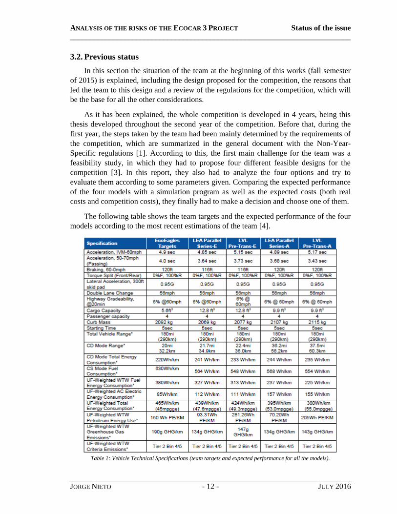
The following table shows the team targets and the expected performance of the four
models according to the most recent estimations of the team [4].
Table 1: Vehicle Technical Specifications (team targets and expected performance for all the models).

ANALYSIS OF THE RISKS OF THE ECOCAR 3 PROJECT Status of the issue
________________________________________________________________________
JORGE NIETO - 13 - JULY 2016
According to this feasibility report, the chosen model was the first one of Table 1,
the LEA Parallel Series – E (whose name comes from the Enerdel motor it uses).
However, due to additional requirements added to the competition, they were forced to
choose the LEA Parallel Series – A instead, whose schematic diagram is shown below.
Figure 3: LEA Parallel-Series-A Component Diagram and Power Flow Diagram
As it is shown in Figure 3, this model has two different electric motors (Bosch IMG),
together with the diesel engine, and two different clutches that allow the motors work in
both parallel and series modes. This configuration allows the car to have 4 different
modes of operation, which are the following:
1. Charge Depleting Mode: use the twin electric motors for a whole electric power
operation (no fuel consumption in this mode).
2. Parallel Load Balancing Mode: in this case the electric motors are used to load
the engine more to let it work within its most efficient ranges, so that the
LEA
A123 18.9kWh
7x15s3P
Bosch IMG
BRUSA
Charger
E85
Front
Rear
Bosch IMG
8L90
8 Speed

ANALYSIS OF THE RISKS OF THE ECOCAR 3 PROJECT Status of the issue
________________________________________________________________________
JORGE NIETO - 14 - JULY 2016
consumption is minimized. This can be considered as a hybrid operation mode,
which will be the most frequent option when driving.
3. SPORT Mode: this is the highest sports performance mode, in which the engine
will operate at full power to achieve its most powerful performance without
taking care of the consumption or the emissions. It will be activated manually by
driver by pressing a bottom.
4. Series Mode: this can be considered as an emergency mode that could be
operated in case of failure of any of the electric motors. In that case, the
corresponding clutch will be open so that the car will operate using only one of
the twins Bosch motors.
With the exception of the Sports mode, the operation of the car will be carried out
automatically by the electronic control system. This will optimized the utilization so that
whenever the car is started with full battery charge it will operate in the first mode until
the battery is depleted until approximately the 30% of its charge. At that point it will
change to mode 2. Driver can press the bottom for Sports Mode in any moment and the
fourth mode will be only activated in case of emergency as explained.
Finally, in the following table taking from the Architecture Selection document all
the main components chosen for this design are shown.
Table 2: Component selection for the selected architecture

ANALYSIS OF THE RISKS OF THE ECOCAR 3 PROJECT Literature Review
________________________________________________________________________
JORGE NIETO - 15 - JULY 2016
LITERATURE REVIEW
1. Introduction to systems safety
System safety can be defined both as a doctrine of management practice that
mandates that hazards be found and risks controlled and as a collection of analytical
approaches with which to practice this doctrine [5]. Systems are analyzed to identify the
possible hazards and those hazards are assessed according to their risks with the aim of
supporting management decision-making. The role of the System Safety group in the
EcoCAR 3 Project is exactly to identify and assess those risks so that the proper decisions
can be made to minimize them.
Being the analysis the main task of this project, it‟s essential to define the tools that
will be used for that purpose before the analysis itself is started. For this reason, in this
section the different methods that are to be considered will be analyzed, explaining the
principles used in them and the usefulness of each for this thesis.

ANALYSIS OF THE RISKS OF THE ECOCAR 3 PROJECT Literature Review
________________________________________________________________________
JORGE NIETO - 16 - JULY 2016
2. Analysis techniques
It has to be borne in mind that there are hundreds of methods when talking about
hazard identification and analysis, and presenting all of them will be beyond the scope of
this work. Therefore, the techniques that are going to be presented are only those who
have been used or will be used for the analysis of the team.
Moreover, the idea is to give a method for each of the traditional analysis approaches
so that all the perspectives are covered. This means presenting one different method for
the deductive, the inductive and the exploratory analysis. Besides, the descriptive
method, which is just based on straight forward observation, is also to be considered.
The following table presents a summary of the approach of each kind of analysis
depending on the variables (causes and effects) that are known.
Causes
Effects Known Unknown
Known Exploratory Inductive
Unknown Deductive Descriptive
Table 3: Approach of different types of analysis based on Causes vs Effects.
Finally, the figure below presents a comparative diagram of the basic reasoning and
approach for each of the three methods that are explained in this section, based on the
Causes vs Effects model.
Figure 4: Summary of the reasoning of the presented techniques.

ANALYSIS OF THE RISKS OF THE ECOCAR 3 PROJECT Literature Review
________________________________________________________________________
JORGE NIETO - 17 - JULY 2016
2.1. Deductive (FTA)
The first approach of any kind of analysis is the deductive. Deduction is defined as a
logical process in which a conclusion is drawn from a set of accepted premises, so that
this result is inferred from no more information that the known facts and those premises.
In hazard analysis, a deductive analysis begins with a defined undesired event, usually a
postulated accident condition, and systematically considers all known events, faults, and
occurrences that could cause or contribute to the occurrence of the undesired event. It
consists mainly of a process of inferring the possible hazards from all that information
known about the analyzed system.
Fault Tree Analysis (FTA) is a popular and productive hazard identification tool,
which provides a standardized discipline to evaluate and control hazards. The FTA
process is used to solve a wide variety of problems ranging from safety to management
issues.
An FTA (similar to a logic diagram) is a "deductive" analytical tool used to study a
specific undesired event, such as a failure in the breaks or the engine. It is a graphical
model that displays the various combinations of equipment failures and human errors that
can result in the main system failure of interest [6]. The identification of risk is derived
by first identifying faults/hazards, so that is called a top down approach.
The procedural steps of performing a FTA are [7]:
1. Assume a system state and identify and state the top level undesired event(s)
clearly. Alternatively, design documentation such as schematics or flow diagrams
may be reviewed.
2. Develop the upper levels of the trees via a top down process. That is to determine
the intermediate failures to cause the next higher level event to occur. The logical
relationships are graphically generated using standardized FTA logic symbols, as
described below.
3. Continue the top down process until the root causes for each branch is identified
and/or until further decomposition is not considered necessary.
4. Assign probabilities of failure to the lowest level event in each branch of the tree.
This may be through predictions, allocations, or historical data.
5. Establish a Boolean equation for the tree using Boolean logic and evaluate the
probability of the undesired top level event.
6. Compare to the system level requirement. If it the requirement is not met,
implement corrective action, which may vary from redesign to analysis
refinement.
As it is stated in the second point, FTA uses sets of symbols, labels and identifiers, as the
ones shown below [8]:

ANALYSIS OF THE RISKS OF THE ECOCAR 3 PROJECT Literature Review
________________________________________________________________________
JORGE NIETO - 18 - JULY 2016
Figure 5: Examples of symbols used for FTA analysis.
2.2. Inductive (DFMEA)
The inductive reasoning is the one in which general principles are derived from
specific observations, that is to say, the premises are viewed as supplying strong evidence
for the truth of the conclusion. While the conclusion of a deductive argument is certain,
the truth of the conclusion of an inductive argument is just probable, based upon the
evidence given. Therefore, an inductive method is the one that is based in several
observations to come up with a general rule or principle.
DFMEA (Design Failure Mode and Effect Analysis) is the application of the FMEA
method specifically to product/service design. The DFMEA can be considered as a
particular case of FMEA which focuses on how product design might fail [9].
The Failure Mode and Effects Analysis (FMEA) method is designed to [10]:
Identify and fully understand potential failure modes and their causes, and the
effects of failure on the system or end users, for a given product or process.
Assess the risk associated with the identified failure modes, effects and causes,
and prioritize issues for corrective action.
Identify and carry out corrective actions to address the most serious concerns.
An FMEA is an engineering analysis done by a cross-functional team of subjects
experts who ae normally assembled by the lead design engineer. This tool is to focus
discussion within a team, not to be done by individuals.
DFMEA is also a graphical approach to collecting data and can be considered as a
logical flow, as shown in the figure below [11].

ANALYSIS OF THE RISKS OF THE ECOCAR 3 PROJECT Literature Review
________________________________________________________________________
JORGE NIETO - 19 - JULY 2016
Figure 6: Logical flow of the FMEA analysis.
There are several different steps to complete DFMEA, which can be summarized
according to the process explained in [12]:
1. Identify components and describe its functions.
2. Identify all the possible failure modes.
3. List potential effects of failure modes
4. Assign the severity ranking which should be based on consequences of failure
(normally ranked in a scale 1 to 10).
5. Identify the cause or causes of the failure mode.
6. Determine the probability of occurrence and rank it (1 to 10).
7. Identify the current controls.
8. Determine the effectiveness of those current controls.
9. Calculate the SOD (Severity x Occurrence x Detection) number or Risk Priority
Number (RPN).
10. Develop action plan to reduce RPNs (The failure modes with the higher RPN
receive priority). Once developed I should be implemented and supervised,
calculating RPN again based on improvements.
2.3. Exploratory (HAZOP)
The third method studied belongs to the exploratory analysis. Exploratory data
analysis can be viewed as a method for comparing observed data to what would be
obtained under an implicit or explicit statistical model [13].
HAZard and OPerability (HAZOP) study is a structured and systematic examination
of a planned or existing process or operation in order to identify and evaluate problems
that may represent risks to personnel or equipment, or prevent efficient operation [14].
The HAZOP technique was initially developed to analyze chemical process systems,
but has later been extended to other types of systems and operations. A HAZOP is a
qualitative technique based on guide-words and is carried out by a multi-disciplinary
team (HAZOP team) during a set of meetings.
HAZOP is a well-known and well documented study, which is normally is used as
part of a Quantitative Risk Assessment (QRA) or as a standalone analysis. The purpose
ANALYSIS OF THE RISKS OF THE ECOCAR 3 PROJECT Literature Review
________________________________________________________________________
JORGE NIETO - 20 - JULY 2016
of the HAZOP is to investigate how the system designed may create risk for personnel
and equipment and operability problems in order to mitigate those risks [W2].
For this reason, the HAZOP study should preferably be carried out as early in the
design phase as possible - to have influence on the design. On the other hand, however,
the HAZOP can be also carried out as a final check, when the detailed design has been
completed, in order to check the correct functioning of the system and identify
modifications that should be implemented to reduce risk and operability problems.
A HAZOP involves a systematic and detailed review of a process by the team,
preferably led by an experienced person independent of the facility being studied. The
HAZOP uses a brainstorming approach around a series of guide words designed to
qualitatively identify possible deviations from normal operation and their possible
impacts. Responsibilities are assigned to investigate possible solutions for each problem
found.
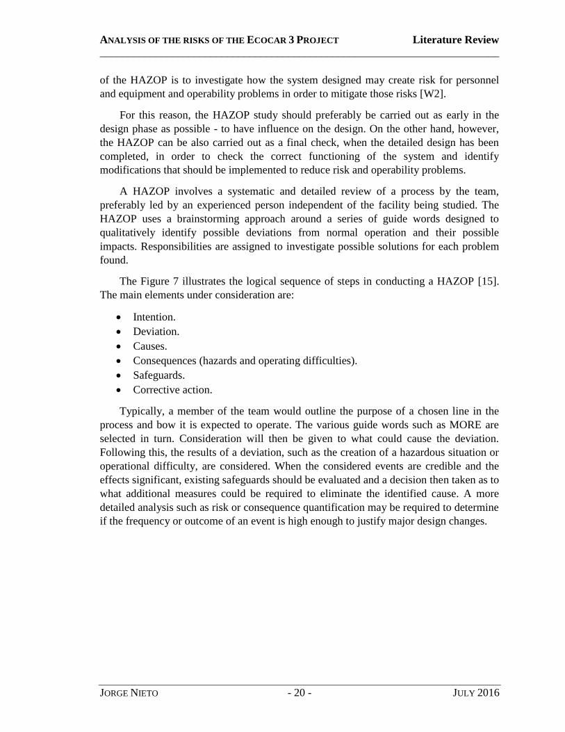
The Figure 7 illustrates the logical sequence of steps in conducting a HAZOP [15].
The main elements under consideration are:
Intention.
Deviation.
Causes.
Consequences (hazards and operating difficulties).
Safeguards.
Corrective action.
Typically, a member of the team would outline the purpose of a chosen line in the
process and bow it is expected to operate. The various guide words such as MORE are
selected in turn. Consideration will then be given to what could cause the deviation.
Following this, the results of a deviation, such as the creation of a hazardous situation or
operational difficulty, are considered. When the considered events are credible and the
effects significant, existing safeguards should be evaluated and a decision then taken as to
what additional measures could be required to eliminate the identified cause. A more
detailed analysis such as risk or consequence quantification may be required to determine
if the frequency or outcome of an event is high enough to justify major design changes.

ANALYSIS OF THE RISKS OF THE ECOCAR 3 PROJECT Literature Review
________________________________________________________________________
JORGE NIETO - 21 - JULY 2016
Figure 7: Logical sequence of steps in a HAZOP.

ANALYSIS OF THE RISKS OF THE ECOCAR 3 PROJECT Literature Review
________________________________________________________________________
JORGE NIETO - 22 - JULY 2016
2.4. Descriptive analysis: observation
Last but not least, many safety issues can be detected by simply observing. For that
reason, spending time in the lab, working with the car or just supervising the main tasks
that other sections of the EcoCAR team are carrying out is considered to be an important
part of the job.
Furthermore, this is also a way to check that the safety measures in the lab are
followed, which can be considered as an indirect additional task of the safety team.

ANALYSIS OF THE RISKS OF THE ECOCAR 3 PROJECT Literature Review
________________________________________________________________________
JORGE NIETO - 23 - JULY 2016
3. Hybrid Vehicles
A hybrid vehicle is defined in general as an automobile that uses two or more
sources of propulsion power. However, hybrid vehicle is commonly used to refer to
hybrid electric vehicles (HEV), which use electric motors as one of the sources of
propulsion power.
In most cases, HEVs are powered by an internal combustion engine or other
propulsion source that runs on conventional or alternative fuel, together with the electric
motor, that uses energy stored in a battery.
This section presents a quick review about hybrid vehicles, including the basis of the
technology and some technical considerations, basic components, degrees of
hybridization and a summary of the architectures of hybrid vehicles, so that it can be used
as a base to contrast the design of the EcoCAR team. The idea is not to include a detailed
explanation about it, but just to provide a basic analysis of the reasoning behind hybrid
vehicles, the HEV technology and the main different models.
3.1. Technical considerations
A conventional vehicle has a mechanical drive train that includes the fuel tank, the
combustion engine, the gear box, and the transmission to the wheels. The logical flow of
the drive train can be seen in the figure below.
Figure 8: Basic outline of the mechanical drive train.
On the contrary, a HEV has two drive trains - one mechanical and one electric. The
second one, the electric drive train, includes a battery, an electric motor, and power
electronics for control. The gear box and the transmission are still part of it, but in this
case the power flows from the electric motor. In Figure 9, the principal layout of an
electrical drive train is shown.
Figure 9: Basic outline of the electrical drive train.

ANALYSIS OF THE RISKS OF THE ECOCAR 3 PROJECT Literature Review
________________________________________________________________________
JORGE NIETO - 24 - JULY 2016
In a HEV these two drive trains can be connected with each other, sharing the same
common components, such as the transmission and gear box. The „hybrid‟ denotation
refers to the fact that both electricity and conventional fuel can be used. Current hybrid
models all use gear boxes, but in the future a single one-gear transmission might be a
reality for series hybrid configurations as the electric drive train can handle a wide variety
of speeds and loads without losing efficiency [16].
In a HEV design, the extra power provided by the electric motor allows for a smaller
engine, resulting in better fuel economy without sacrificing performance. As a
consequence, HEVs combine the benefits of high fuel economy and low emissions with
the power and range of conventional vehicles [17].
Furthermore, that allows to adjust more the design, trying to adapt it to the real
requirements (e.g. according to the necessary torque at the wheels and the desired
performance for speed and acceleration). Current researches are trying to develop motors
according to the demand and of torque and speed at the wheels. Mismatch is only a
problem for gas engines, electric motors can in fact be designed to satisfy wheel demands
[18]. For this reason, HEV vehicles are focusing on optimizing the design more and
more.
3.2. Basic components
As it can be expected, there are thousands of components in hybrid vehicles,
including both basic components of every vehicle and specific elements for HEVs.
Furthermore, there are differences in the components depending on the degree of
hybridization, as it is explained in the following section
For this reason, there is no point in explaining the whole design of a HEV and this
section will present just the main components that have to be considered in a basic
analysis of HEVs in general. Those main components are the following [19]:
Fuel tank: as the name indicates this is the duel deposit of the vehicle. Normally,
it does not differ from the tank of a regular gas-powered car.
Combustion engine: the gasoline engine is the part of the hybrid that resembles its
traditional counterpart, the gas-powered vehicle. It's just like the engine of a
traditional car, except that it is smaller, thus requiring less fuel to function [W3].
This smaller size is achieved by considering the extra power given by the electric
motor in the design.
Electric motor: there can be just one or several electric motors, and they are used
both as a generator to harness energy wasted from braking or coasting or as a
motor to run the vehicle. However, in most cases both functions are separated so
that the generator is considered to be another component, as it is shown in this
example.

ANALYSIS OF THE RISKS OF THE ECOCAR 3 PROJECT Literature Review
________________________________________________________________________
JORGE NIETO - 25 - JULY 2016
Generator: it is the component in charge of harnessing the energy losses from the
brakes or from coasting. That energy is stored in the battery and used later to
power the electric motor.
Battery: it is one of the key elements of a HEV. The battery is used to store the
electric energy. In the plug-in HEVs this energy comes from the power outlet,
whereas in the mild or full HEVs it comes from other parts of the car (energy
given by the engine, regenerative braking).
Transmission: the functioning of the transmission is the same than in traditional
vehicles, transmitting the power from either the engine or the electric motor.
As it has been said, there are many different possibilities, but an approximation of
the display of those main components is shown in the diagram below.
Figure 10: Main components of a hybrid car.
3.3. Degrees of Hybridization
As it happens with most engines or devices in general, petrol engines use only a part
of the energy that is contained in the fuel, so that most of that energy is lost as heat, as
well as in some other inefficiencies such as engine friction. For this reason, the average
efficiency of a car engine is around 17-20%. Furthermore, 20-30% of that energy is lost
while braking and more than 10% is lost during idling, which means that at the end only a
low percentage which is normally between 12 and 14% of the energy supplied is actually
used to move the car [16].

ANALYSIS OF THE RISKS OF THE ECOCAR 3 PROJECT Literature Review
________________________________________________________________________
JORGE NIETO - 26 - JULY 2016
However, hybrid electric vehicles are able to deal with some of these energy losses
and use different technologies to use that lost energy again. Depending on the
technology, the efficiency or the performance of the car, the amount of energy recovered
is smaller or larger, and this criterion is used to classify the car in different degrees of fuel
efficiency. These degrees range from “mild HEV”, to “full HEV” and “PHEV” (plug-in
hybrid electric vehicles), and they are summarized in ascending order in the table below.
Step Technology Degree of hybridization
1 Avoiding energy losses during idling by shutting
off the combustion engine. Mild HEV
(e.g. Honda Civic) 2 Recuperating energy from regenerative braking.
3 Using the battery energy to assist the engine and
enable downsizing the engine
4 Running the combustion engine at its maximum
load, where the engine efficiency maximizes. Full HEV
(e.g. Toyota Prius) 5 Driving without the combustion engine running
6 Enlarging the battery pack and recharging it with
energy from a wall plug
PHEV
(e.g. Chevrolet Volt)
Table 4: Degrees of hybridization.
Step 1: The first step consists of a reduction of the energy losses while idling. As
it has been said, this means more than 10% of the energy consumption of the
engine and this lost can be reduced by allowing the combustion engine to shut
down or run at maximum load to recharge the battery during this time.
Step 2: The use of an electric drive train enables the HEV to recuperate part of the
energy losses during braking, and it can then be used “backwards” as a generator
to charge the battery. Therefore, the conventional brake pads will be used on
some occasions, only with sudden and hard braking, which implies a collateral
advantage as the life of the brake pads will be much longer and the costs due to
replacement will be reduced.
Step 3: Most combustion engines are typically designed for a range of maximum
output which is much larger than the energy requirement for most of the time
during normal driving, resulting in low efficiency. In a hybrid, when higher power
is needed, such as uphill drives or when accelerating, extra power is temporarily
delivered by the battery. As a consequence, theoretically the engine size can be
designed for a lower range of outputs, normally between 15 and 30 kW, which is
the average power needed during normal driving.

ANALYSIS OF THE RISKS OF THE ECOCAR 3 PROJECT Literature Review
________________________________________________________________________
JORGE NIETO - 27 - JULY 2016
Step 4: As a consequence of the previous explanation, an ordinary combustion
engine (diesel or petrol) operates at maximum engine efficiency for an output
level close to its maximum power. When the engine is smaller and the excessive
delivered power is used for recharging the batteries, the combustion engine can
run at its maximum load at most of the time and the performance is maximized.
Step 5: This steps allows the possibility of driving without the combustion engine
running, and thus zero emissions, which can be especially useful when driving at
low speed or in congestion in urban areas. The current limitation is that currently
full HEVs have small battery packs. However, statistics prove that most of the
time cars are driven within urban areas and the average single-trip distance is
actually lower than 6 miles in the US [W4], which allows battery-only operation
in most trips if the battery is relatively large.
Step 6: The final step in hybridization are plug-in hybrids, based on rechargeable
batteries of bigger capacity that increase battery-only driving range. Because of
the larger capacity, it is worthwhile to charge the battery from a conventional
power plug as the charging times are considerably lower.
3.4. Architectures
Each HEV can have a different architecture, but there are some basic configurations
that are used in most vehicles. Those configurations differ mainly in the power flow. In
some cases the gas engine is used just to give power to the battery and the electric motor
is the one that runs the vehicle (series architecture), in some others both of them work
independently to run the vehicle (parallel architecture) and in the last cases the engine can
give be connected either to the transmission or the generator (power-split or complex
architectures) [20].
This section presents the main cases, including a diagram as an example for each. In
those diagrams the tick simple lines represent the electric connections and the double
lines represent the mechanical connections, whereas the simple thin lines represent any
other kind of connection, such as the fuel flow.
3.4.1. Series
The series hybrid, just like electric vehicles, is an architecture in which the electric
motors are only used as propulsion power. Instead of having a large capacity battery pack
on board, series hybrid carry an engine generator set on board [21].
This functioning requires that all energy that goes to the wheel has to at least be
converted once. Thus, efficiency gain is limited compared with a conventional vehicle.
Series hybrids are popular in some low-speed and high-torque applications where engine
efficiencies are low.

ANALYSIS OF THE RISKS OF THE ECOCAR 3 PROJECT Literature Review
________________________________________________________________________
JORGE NIETO - 28 - JULY 2016
The figure below presents the basic configuration of the series architecture.
Figure 11: Series hybrid architecture.
3.4.2. Parallel
The parallel hybrid has two propulsion systems, the IC engine and the electric motor,
that can be operated at the same time or independently. These two propulsion systems
can be all connected to the wheel, or can be send propulsion to different axles and
connected through the road [22]. Parallel hybrids are able to achieve a higher efficiency
by operating the engine or the motor or combined depending on the driving situation
without suffering much additional losses.
The figure below presents the basic configuration of the parallel architecture.
Figure 12: Parallel hybrid architecture.

ANALYSIS OF THE RISKS OF THE ECOCAR 3 PROJECT Literature Review
________________________________________________________________________
JORGE NIETO - 29 - JULY 2016
3.4.3. Power-Split (series-parallel)
Power-split hybrids, also called series-parallel hybrids, are a special kind of hybrids,
which can be considered as a combination of both. Power-split can pass engine power to
the wheel either mechanically (parallel) or electrically (series).
For this reason, it combines the advantages of a series and a parallel [23]. It has a
direct mechanical path for the ICE, which is very efficient in steady operating conditions
like cruising. Furthermore, another advantage is that it has an electromechanical path
which allows for efficient operation of the ICE in unsteady driving, such as speed
variations seen in city driving. The combination of both of them allows, thus, a higher
efficiency in both steady and unsteady driving.
On the other hand, it has the disadvantage of having further complexity and cost.
The figure below presents a diagram of the basic components and connections of this
kind of architecture.
Figure 13: Series-parallel hybrid architecture.
3.4.4. Complex hybrids
The last architecture includes any other kind of configuration with a higher level of
complexity, including more elements or connections that the simple architectures that
have been explained before.
Complex hybrids can be designed to meet any specific requirements, but obviously
the costs and the technical difficulty are higher.
There are many different possibilities, so that the figure below is just one of the
multiple possible examples of a complex hybrid.

ANALYSIS OF THE RISKS OF THE ECOCAR 3 PROJECT Literature Review
________________________________________________________________________
JORGE NIETO - 30 - JULY 2016
Figure 14: Complex hybrids architecture.
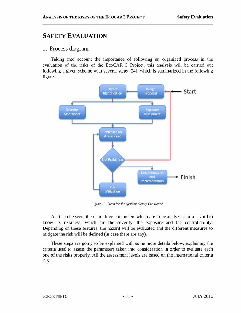
ANALYSIS OF THE RISKS OF THE ECOCAR 3 PROJECT Safety Evaluation
________________________________________________________________________
JORGE NIETO - 31 - JULY 2016
SAFETY EVALUATION
1. Process diagram
Taking into account the importance of following an organized process in the
evaluation of the risks of the EcoCAR 3 Project, this analysis will be carried out
following a given scheme with several steps [24], which is summarized in the following
figure.
Figure 15: Steps for the Systems Safety Evaluation.
As it can be seen, there are three parameters which are to be analyzed for a hazard to
know its riskiness, which are the severity, the exposure and the controllability.
Depending on these features, the hazard will be evaluated and the different measures to
mitigate the risk will be defined (in case there are any).
These steps are going to be explained with some more details below, explaining the
criteria used to assess the parameters taken into consideration in order to evaluate each
one of the risks properly. All the assessment levels are based on the international criteria
[25].

ANALYSIS OF THE RISKS OF THE ECOCAR 3 PROJECT Safety Evaluation
________________________________________________________________________
JORGE NIETO - 32 - JULY 2016
Hazard Identification
The first step of the evaluation corresponds to the identification of the potential hazards.
This process will be done using the methods explained in the section Analysis techniques
and it will be the main issue of this work.
Severity Assessment
Once a potential risk has been identified the next step is to assess the severity of each
hazard. According to their severity the risks can be classified in three levels:
S1 None or Light Injuries.
S2 Moderate to Severe Injuries.
S3 Severe to Lethal Injuries.
Exposure Assessment
The next parameter to be considered is the exposure assessment. There are four levels in
which the exposure can be classified, which are the following:
E1 Very low probability.
E2 Low probability.
E3 Medium probability.
E4 High probability.
Controllability Assessment
The last parameter that defines the severity of a potential hazard is the controllability,
which can also be classified in three different levels:
C1 Simply controllable.
C2 Normally controllable.
C3 Difficult to control.
Risk Evaluation
When a risk has been assessed according to the severity, the exposure and the
controllability it can be then evaluated. There are five different levels of riskiness
according to the standard used, the Automotive Safety Integrity Level (ASIL) Grade,
which are the following:
QM Quality Management.
A Low.
B Medium.
C High.
D Very High.

ANALYSIS OF THE RISKS OF THE ECOCAR 3 PROJECT Safety Evaluation
________________________________________________________________________
JORGE NIETO - 33 - JULY 2016
The table below summarizes how to determine the ASIL level depending on the three
parameters analyzed.
Table 5: ASIL Determination (Severity · Exposure · Controllability).
Risk Mitigation
Once the ASIL level has been determined for a particular hazard the last step is to create
a list of requirements or recommendations (depending on the riskiness) in order to
minimize and mitigate the possible effects of the risks. The list shall be clear and concise,
with specific comments and concrete measures to be taken.
Documentation and implementation
Finally, in order for the team to keep its procedures, it is important to prepare the
documentation properly so that the proposed measures can be carried out.
For that purpose, there is a process in order to get the approval from the person in charge
of the affected department, the advisor, the managers and the Safety Board. This process
to test authorization consists of:
Written authorization of testing:
Procedural Mitigations.
Operational Limitations.
Required Signoffs:
Engineering Manager.
Systems Safety Manager.
Faculty Advisor.

ANALYSIS OF THE RISKS OF THE ECOCAR 3 PROJECT Safety Evaluation
________________________________________________________________________
JORGE NIETO - 34 - JULY 2016
The whole is summarized in the figure below.
Figure 16: Process to get the approval for any changes due to the safety analysis.

ANALYSIS OF THE RISKS OF THE ECOCAR 3 PROJECT Safety Evaluation
________________________________________________________________________
JORGE NIETO - 35 - JULY 2016
2. Regulations
All the analysis has to be done according to the current normative. This includes both
the International Standard presented in the previous section [25], and the specific
regulations for the competitions, presented in the section Competition rules. As it was
explained in that section, both the Specific rules for the year 2, and the general
regulations for the whole competition have to be considered.
For this reason, the analysis and understanding of all these regulations is basic for the
analysis. As a consequence, one of the main tasks of the team was to have a couple of
members in charge of this field, whose task was to analyze the most important rules and
update a summary within the group database so that everyone could access it.
This summary was also very important for the requirements, as it was necessary to
link each of the requirements with any rule that was related to it. For that reason, having a
short version of the rules, organized according to the criteria of the group, was very
useful for an efficient research on the rules while doing the requirements.
This task was not directly a part of the analysis and it was assigned and carried out
by other members of the Safety section, so that it cannot be considered as an intrinsic part
of this thesis. However, the rules were essential to do the requirements and it was part of
this work to use this summary in order to refer the rules in the requirements database. For
this reason, some of the most important or most frequently-used rules are mentioned
below, but the whole summary can be found at the end of the present document, as an
appendix.
The rules that are mentioned below are labeled according to the criterion of the team
classification. For each of the four examples, the original context of the regulations is
explained together with the summary of the team.
Rule 0066
This rule belongs to the section I-1.3 of the non-year specific rules [1]. The section I
present the design rules for the electric systems, and the third part is specifically about
wire and terminal protection. The content of that part of the section is copied below:
“All wiring inside the vehicle must not be run in paths where it may get crushed or
otherwise damaged. All wiring on the exterior of the vehicle must be run through split
loom or an equivalent protective conduit. All wiring must be protected from chafing on
sharp edges or where it passes through a panel. When a wire must pass through a frame,
panel, or bulkhead, it must be protected by cable grips or grommets securely fastened to
the opening. All wiring must be strain-relieved and securely fastened throughout the
vehicle to minimize movement.
Wires that may be damaged by moving parts, bending, chafing on corners or
surfaces, pinching, crushing, high temperatures, or corrosive liquids must be protected by

ANALYSIS OF THE RISKS OF THE ECOCAR 3 PROJECT Safety Evaluation
________________________________________________________________________
JORGE NIETO - 36 - JULY 2016
an appropriate nonmetallic protective conduit or similar protection. Such wiring includes
all wiring in the underbody and in the under-hood areas of the vehicle. Wires must be
secured to prevent them from getting caught in rotating parts, falling on hot surfaces, or
snagging on road features.”
This explanation is summarized in the database in four different rules, which are
numbered from the Rule 0066 to the Rule 0069. The first one of these four rules is the
most frequent of the section in the requirements that are already done and its content is
“All wiring inside the vehicle shall not be run in paths where it may get crushed or
otherwise damaged.” This condition affects, for instance, to the requirements that
determine the resistance of the ESS to an external impact.
Rule 0098
The rule 0098 has been deduced from the same section of the non-year specific rules
too, but in this case it summarizes the content of the part I-3.12, which is about
conductive enclosures. The content of that part of the section is copied below:
“When using conductive boxes and covers, teams must design the box/cover or lid so
that it can never come into contact with the enclosed components. Covers, boxes, and
shielding must not be designed or intended to carry current. All metal enclosures
containing HV must be grounded to the chassis of the vehicle. Likewise, any non-current-
carrying conductive elements passing through the enclosure (bolts, rivets, etc.) must be
grounded to the chassis of the vehicle. The ground connection must be capable of full
fault current. There must be an insulating material between any conductive HV
component and the enclosure. Insulating sprays are not acceptable. All insulating barriers
and coatings must be tough enough to prevent HV parts from cutting through in the event
of hard contact.”
This explanation is summarized entirely in this rule, which has been included in the
database of the team as “All insulating barriers and coatings shall be tough enough to
prevent HV parts from cutting through in the event of hard contact.” As the name of the
section says this rule affects to any conductive enclosure so that an example in which the
rule has to be considered could be the enclosure of the battery pack.
Rule 0112
The last rule that is included as an example belongs to the section J-2.1 of the
regulations. All the second part of the section J is about the fuel tank design, being the J-
2.1 a description of the general design requirements. This general requirements
description is copied below:
“Teams are not permitted to use the fuel tank that came with the production vehicle.
SFI-rated motorsports fuel tanks are highly recommended. The mounting of all tanks
must be designed to withstand an 8g vertical static load and 20g longitudinal and lateral
ANALYSIS OF THE RISKS OF THE ECOCAR 3 PROJECT Safety Evaluation
________________________________________________________________________
JORGE NIETO - 37 - JULY 2016
static loads. Under these loadings plus a factor of safety of 1.5, the structure must not
enter the plastic region of deformation. Justification of the integrity of the mounting
structure is required to be included in the In-Vehicle Safety Binder.”
This whole paragraph is summarized in the rule 0112, which is included in the
database of the team as “The mounting of all tanks must be designed to withstand an 8g
vertical static load and 20g longitudinal and lateral static loads. Under these loadings plus
a factor of safety o f1.5, the structure must not enter the plastic region of deformation.”
As it can be seen in this example, the rules of the database are just a summary of the
regulations of the competition. Sometimes they cannot be summarized, as all the specific
quantitative details have to be included, but the summary is still useful to have all the
rules organized and labeled, so that they can be used for the requirements or as a
reference of search in case of any doubt within the design.
In this last example, the rule 0112 would be applied as a requirement itself that
determines the vertical, longitudinal and lateral maximum loads.

ANALYSIS OF THE RISKS OF THE ECOCAR 3 PROJECT Safety Evaluation
________________________________________________________________________
JORGE NIETO - 38 - JULY 2016
3. HAZOP analysis
As it has been explained in the section Analysis techniques, the HAZOP is one of the
most complete techniques that can be applied for a safety analysis, because it involves an
exploratory reasoning that comes from any possible single deviation and then analyzes
both possible causes and effects. Therefore, this involves a brainstorming process in
which the goal is to come up with the consequences that the single deviation can have.
In the present section, the objective is to present some of the parts of the HAZOP,
explaining the process of some particular examples as well as the most important
conclusions of the analysis, so that the reasoning behind the analysis can be understood.
Therefore, this reasoning can be considered as a tool that allows understanding of other
parts of the HAZOP that are not explained in detail. It would be pointless to explain
every single case that has been analyzed, as the goal is to emphasize the systems whose
results are more interesting.
Once again, it is important to take into account that this is just the beginning of a
process that will be developed for two more years, so that the HAZOP is not only
incomplete, but also unlikely. However, this does not mean that the thesis is not
complete, as this is a “living” document and one of the purposes is actually to suggest
which parts should be improved or completed in the future.
Finally, it should be reminded that the HAZOP was done in collaboration with other
members of the group, as the idea of the analysis is that is has to be carried out by a
group people in several meetings, so that they build the analysis from the ideas of a
brainstorm process in each meeting. In accordance with the theory of the analysis, each
meeting was supervised and overseen by one of the members, and then all the
conclusions have been summarized in a table within the group database.
There are four sections of the HAZOP that can be considered as fully done, which
correspond to the four subsystems that are presented below. For each of the sections
some parts of the analysis will be just presented or sometimes explained, and there are
also some comments on the relevant results and conclusions.
3.1. ESS
The Energy Storage System (ESS) is one of the key elements for the design of a
hybrid car, and so is it in terms of safety, where it can be considered as one of most
important parts considering that it involves dealing with HV risk.
As it was shown in the section Previous status, the ERAU design has the A123
18.9kWh ESS. This battery was donated to the team and it provides increased CD range
and a higher utility factor, allowing the vehicle to travel approximately 40 miles of
battery-only driving.

ANALYSIS OF THE RISKS OF THE ECOCAR 3 PROJECT Safety Evaluation
________________________________________________________________________
JORGE NIETO - 39 - JULY 2016
The Camaro ESS stats are the following:
0-60 mph in 4.9 seconds
53 mpgge (miles per gallon gasoline equivalent)
180 miles of total range (all electric range of 40 miles, as commented).
However, there are many risks associated with this key element. Some of them are
presented in the Table 6 in the form of a HAZOP analysis, which is going to be explained
below.
Sys_Func Weatherp
roofing Luggage support
Emergency safety
Cabin Isolation
Not_Provided
Weather exposure, HV risk, fire risk
Weather exposure, HV risk, fire risk, component
damage
HV & fire risk to occupants, HV & fire risk to
first responders
Exhaust exposure to occupants &
trunk
Provided_ Incorrect
Weather exposure, HV risk, fire risk
Limited luggage capacity (mass)
Same N/A
Too_Much Overpres
sure, weight
Weight, handling
compromised, luggage
storage (vol.)
Weight Weight
Too_Little
Weather exposure, HV risk, fire risk
Limited luggage capacity (mass)
HV & fire risk to occupants, HV & fire risk to
first responders
Exhaust exposure to
trunk
Wrong_ Direction_
Polarity N/A
Inefficient use of space
N/A N/A
Too_Soon N/A N/A N/A N/A
Too_Late N/A N/A N/A N/A
Stuck Maint.
Compro-mised
N/A N/A Maint.
compromised
Table 6: HAZOP analysis for some of the elements that affect the ESS.

ANALYSIS OF THE RISKS OF THE ECOCAR 3 PROJECT Safety Evaluation
________________________________________________________________________
JORGE NIETO - 40 - JULY 2016
Weather proofing
The first functionality to be explained is going to be the weather proofing. Being the first
case, this will be used as an example of how to build a HAZOP analysis, explaining how
to fill in each of the cells according to the condition considered.
The possibilities that have to be analyzed for each case in the HAZOP analysis according
to the regulations given are the following:
Not provided: this first case is easy to understand, the goal is to analyze what
would happen or what are the risks whether the feature considered is not
provided. In this example, not having proper ESS weather proofing would involve
several risks. Obviously, this would mean that the ESS is exposed to any weather
conditions, and this increases the risks of fire and the risk associated to the HV.
The reasoning in this case is simple: the battery could get wet and would be more
sensitive to the temperature, which is not desirable.
Provided incorrectly: this condition refers to the possibility that the object of
analysis is provided, but not in the appropriate. In this case, an example in which
the weather proofing could be provided incorrectly would be if the ESS was
sealed against the rain coming from the top, but not prepared for a splash coming
from the bottom (for instance, water coming from a puddle). This is considered as
an incorrect weather proofing because the battery could get wet under some
conditions despite the fact of having a waterproof protection. The hazards in this
case are the same that were considered in the previous one, but the potential risk
could be considered even higher, because it could be thought that the vehicle is
protected against it when actually is not.. For this reason, it is always important to
keep this condition in mind, as there are examples in which a protection which is
supposed to be provided is useless for not being provided correctly.
Too much: this label refers to the possibility of something provided in an
excessive way, which implies collateral hazards. In the example of weather
proofing for the ESS, an excessive protection might be associated with extra
weight and overpressure.
Too little: this refers to the opposite, provided just for low levels. Most of the
times the risks of this low protection are the same that were considered when not
provided, and that is what happens in this example. Obviously, it is always better
to have low protection rather than not having protection at all, but the hazards are
still the same (although the risk might be slightly lower).
Wrong direction (polarity): this can be applied for characteristics that are
polarized or for elements that have to provide a service in one specific direction.
In the example that is being considered this cannot be applied.

ANALYSIS OF THE RISKS OF THE ECOCAR 3 PROJECT Safety Evaluation
________________________________________________________________________
JORGE NIETO - 41 - JULY 2016
Too soon: this label refers to something being provided before it is actually
needed. It applies to features or services that are provided within a temporal scale,
that is to say, that need some time to be provided. In some cases this could be
important, as far as the feature is provided, but there are other cases in which a
forward supply can have several risks. Once again, this cannot be applied in the
current example, as the weather proofing is a fixed (non-temporal) feature.
Too late: this is exactly the opposite case of the previous one, as it refers to a
delay of a feature. In a driving context, most of the times providing something too
late is not desirable, although there are some particular cases in which it might not
be important or applicable. As it happened with the previous case, this label
cannot be considered in this example.
Stuck: the last label makes reference to the possibility of something getting stuck.
There can be several reasons that prevent a feature from being provided because it
is blocked, and most likely it is not an ideal event to occur. In this case having the
weather proofing stuck is not something really common and it would not be
applied except for maintenance issues.
These eight possibilities are the ones that have to be considered for the HAZOP
analysis in any cases. As it has been explained, there are several examples in which some
of them are not applied, but it is important to fill in the corresponding cells to make sure
that the reasons are understood. Obviously, there are some analyses which are quite
simple, but in other cases they can get more complex and that is why it is highly
recommended to carry out a HAZOP analysis by a team. No matter how unlikely an
event is, it still has to be considered and sometimes included, and for this reason it is
positive to have several opinions and use brainstorms in the meetings, so that the
maximum number of possibilities are discussed.
Throughout this section, other parts of the HAZOP analysis are explained, making
some relevant comments on those results which are more important or surprising.
Luggage support
The ESS is located in the rear part of the vehicle, which means that it is close to the
trunk. Therefore, a luggage support is required for safety reasons. This piece might not
seem relevant on a quick review, but it is actually very important as it is something that
might be easily forgotten and that could cause a big issue if it is not designed properly.
The results for a HAZOP analysis prove that in case the luggage support protection is
not provided the battery could be damaged and it could result in a high fire or HV risk. It
could be considered to be provided incorrectly in those cases in which the design is not
correct and the resistance is lower than expected or could fail. Anyway, it could also be
considered as not applicable, because this would be the same situation that what happens

ANALYSIS OF THE RISKS OF THE ECOCAR 3 PROJECT Safety Evaluation
________________________________________________________________________
JORGE NIETO - 42 - JULY 2016
when it is provided below the minimum requirements. Both cases would require a weight
limit (extra weight would mean a high risk for the battery, as the support could break. For
the opposite case, when it is provided excessively, that mean a reduction of the trunk
space, which means less luggage for the user (volume limitation), whereas). Finally,
having the support in the wrong direction would be an inefficient use of space, and
sometimes it could also be a risk if the support does not resist axial forces.
Emergency safety
Although this case is very important, the results of the analysis are quite obvious: if
emergency safety is not provided, provided incorrectly or at a low level the risk of fire
and HV for the occupants will be extremely high and undesirable.
Cabin isolation
The failure of the cabin isolation has revealed several problems and potential hazards
under the different hypothesis analyzed. If the protection is not provided that would mean
that the occupants and the truck would be exposed to the exhaust. The problem would be
the same if it is provided below the requirements and the case of not being provided
correctly is not considered because it could be included either in „not provided‟ (if the
cabin isolation fails) or „too low‟(some problems in the isolation that makes it
incomplete).
In this example the temporal conditions cannot be applied either. Exhaust sealing is
either there or not, so that if the protection works late then it does not work well.
Finally, if the cabin isolation is stuck it would have to be fixed during maintenance
and it would obviously be a high potential risk.
3.2. Oil System
The second analysis to be explained is the HAZOP for the oil system, which is a very
important one in terms of safety as oil issues are always one of the most frequent
problems of most cars and it therefore requires an appropriate maintenance.
The Internal Combustion Engine (ICE) is probably the main part for every single
vehicle. Surfaces in contact and relative motion to other surfaces require lubrication to
reduce wear, noise and increase efficiency by reducing the power wasting in overcoming
friction, or to make the mechanism work at all. Oil also helps to cool the engine and to
keep it clean, eliminating impurities. Making sure that the oil systems works fine and
lubricates the ICE is therefore a must-do in terms of safety, and probably the main task of
the oil system.
In the Table 7 some of the features analyzed in the HAZOP are presented, and they
will be commented below.

ANALYSIS OF THE RISKS OF THE ECOCAR 3 PROJECT Safety Evaluation
________________________________________________________________________
JORGE NIETO - 43 - JULY 2016
Sys_Func Lubricate ICE Renew oil Provides cooling
Pressurizes Houses
oil
Not_Provided ICE failure
localized component
heating, impurity build up,
degradation of oil
Reduced component
life cycle ICE failure No oil
Provided_ Incorrect
Risk of ICE failure
Inefficiencies, risk for the ICE
N/A Uneven oil distribution
N/A
Too_Much Inefficient ICE
operation, seal failure
Cost ineffective Inefficient
ICE operation
Leaks cavitation, oil breakdown
Weight
Too_Little
Inefficient ICE,
increased wear
localized component
heating, impurity build up,
degradation of oil
Reduced component
life cycle
ICE failure, uneven oil
distribution
ICE failure
risk
Wrong_Direction_Polarity
N/A N/A N/A
ICE failure, uneven oil
distribution, cavitation
N/A
Too_Soon N/A N/A N/A N/A N/A
Too_Late ICE failure, increased
wear N/A N/A N/A N/A
Stuck N/A N/A N/A N/A N/A
Table 7: HAZOP analysis for some of the features of the Oil System.
Lubricate ICE
First of all, the HAZOP analysis concludes the lubrication is not provided, the engine
will probably not be able to work at all. If it is provided incorrectly then there might be
some issues on the ICE depending on the problem with the lubrication. Anyway, an
inconsistent supply of the oil lubrication could involve problems such as excessive
friction or an undesirable pressure.
Providing too much oil lubrication would be inefficient, and providing too little
would imply the same issues that were commented for an incorrect supply, which is also
inefficient. There is no a way in which it would be provided too soon, but it could be
provided too late, meaning that the flow of oil is slower than what is should, and the
problems in this case would be the same ones that have been explained.

ANALYSIS OF THE RISKS OF THE ECOCAR 3 PROJECT Safety Evaluation
________________________________________________________________________
JORGE NIETO - 44 - JULY 2016
Renew oil
As it was said in the beginning of this section the correct maintenance of the oil
system is essential for the car. For this reason renewing the oil regularly, according to the
advice given by the maker, is very important for a good performance of the engine.
Typically, the recommendation is to change the oil every 3000 miles, although this is not
a fix rule and it also depends on other conditions, such as the use and the driving style
[W5].
According to the HAZOP analysis, is this renovation is not provided that would
damage the engine in the long-term, as it will cause problems such as overheating and a
larger number of impurities and dirt due to the degradation of the oil. An incorrect oil
renewal could be considered as a renovation using low quality oil, or renewing the oil
incorrectly, that is to say, without cleaning all the used oil properly. Any of this cases
would imply problems as the ones commented before and it would be a potential hazard
for the ICE.
Finally, the „too much‟ label would mean in this case changing the oil too often,
which is not bad for the engine, but it is inefficient and costly. On the other hand, using
the same oil for longer than advised would have the same risks that have been already
explained. All the other possibilities are not applicable in this case.
Provide cooling
Cooling the engine is another task that is done by the oil. If this cooling is not
provided, the engine would work at higher temperatures, which will reduce the life cycle
of some components. The other two cases that can be applied in this HAZOP analysis are
the excessive cooling and not enough. The first one would be inefficient, while the
second one will also affect some components negatively. All the other cases do not apply.
Pressurizes
Keeping the pressure is essential to make the oil flows as required. If this pressure is
not provided, the oil will not flow and the ICE will fail. If the pressure is provided
incorrectly, the oil would not be distributed properly and the ICE might fail. An example
in this case could be having inconsistent pressure.
If the pressure is too high it will lead to problems such as leaks, cavitations and oil
breakdown. On the contrary, if the pressure is too low, the oil distribution will be uneven
and once again the engine might fail. In this case it could be considered that the label
„Wrong direction‟ would correspond to pressurizing in a way that makes flow the oil in
the opposite direction, which would cause several of those problems and would probably
make the ICE fail.
ANALYSIS OF THE RISKS OF THE ECOCAR 3 PROJECT Safety Evaluation
________________________________________________________________________
JORGE NIETO - 45 - JULY 2016
Housing oil
The last analysis on the oil system affects the storage. Obviously, the first conclusion
is that if this is not provided then there will be no oil. Apart from this, there is a
possibility that the oil storage is excessive, which results in an excessive way, or that it is
too low, which would be risky for the ICE.
3.3. Fuel System
The fuel system is the responsible for providing, storing and guaranteeing a safe
supply of fuel in the vehicle. The most important task of the fuel systems is providing
fuel to the ICE. Without the proper supply of fuel, the engine would not be able to work
at all. Thus, providing fuel properly is essential to guarantee a good functioning of the
ICE.
In the Table 8 some of the most important features of the HAZOP analysis for the
fuel system are summarized. Those features are commented below.
Provide fuel to ICE
The HAZOP analysis confirms the importance of the fuel system for a correct
functioning of the engine, as it concludes that this would not work if fuel is not provided.
Similarly, if fuel is not provided correctly, the ICE would work inefficiently and might be
damaged or even not work at all.
If there is too much supply of fuel, the ICE would run too rich, which would increase
the emissions up to unacceptable levels, apart from being inefficient. If the supply is not
enough the ICE might not be able to provide the power required and the functioning
would be inefficient.
In this case, it could be considered that the label “Wrong direction” refers to the
possibility of having a fuel flow which does not correspond to the logical sequence of
fuel flowing from the deposit to the engine. If that happened the ICE would not be able to
run and it could be seriously damaged.
With reference to the temporal scale, both providing fuel too soon and too late would
be inefficient and risky for the valves. Finally, if the supply gets stuck there would be a
high fire risk and hydro-lock.
Condense evaporated fuel
Condensing evaporated fuel is a complementary task of the fuel system and is used
to make the most of the fuel and re-use the fuel that has been evaporated but has not been
burnt yet. For this reason, the HAZOP determines that if this feature is not provided or
provided too little it is a loss of fuel (due to the inefficient use) and it increases the risk of
fire.

ANALYSIS OF THE RISKS OF THE ECOCAR 3 PROJECT Safety Evaluation
________________________________________________________________________
JORGE NIETO - 46 - JULY 2016
Table 8: HAZOP analysis for some of the features of the Fuel System.
Maintain pressure
Keeping the pressure at the right level is very important to guarantee that the supply
of fuel is correct. If this is not provided at all, then the operator would be expose to the
fuel, there would be a high risk of fire and also fuel leaks, so probably the system would
fail and the engine would not work. Additionally, if it is not provided correctly (e.g. the
pressure is maintained but it is not totally stable or it the pressure level does not
correspond to the requirements the whole time) the problems would arise.
Sys_Func Provides fuel
to ICE Condenses Evap fuel
Maintains pressure
Maintains fuel level
Fire prevention
Not_Provided No ICE
operation Air in fuel system
Loss of fuel Fire risk
Fuel exposure to
operator Fire risk
Fuel leaks
Unknown fuel level
Unsafe operating,
maintenance and emergency
conditions
Provided_Incorrect
Inefficient operation, risk
for ICE N/A Same risks
Unreliable data
N/A
Too_Much ICE runs rich
Bad emissions N/A
Implementation issues
(complexity)
Implementation issues
(complexity) Weight
Too_Little ICE runs less Inefficient operation
Loss of fuel Same as 'Not
provided' Not precise
enough Same as 'Not
provided'
Wrong_Direction_Polarity
No operation, possible
damages to ICE N/A N/A N/A N/A
Too_Soon Ineffective fuel delivery Risk
to valves N/A N/A N/A
Cannot refill fuel
Too_Late Ineffective fuel delivery Risk
to valves N/A
Pressure build up over
time
Unreliable data to
operator
Same as 'Not provided'
Stuck Fire risk
Hydrolock N/A N/A
Unreliable data to
operator
Same as 'Not provided' /
Cannot refuel

ANALYSIS OF THE RISKS OF THE ECOCAR 3 PROJECT Safety Evaluation
________________________________________________________________________
JORGE NIETO - 47 - JULY 2016
If the pressure is maintained correctly but at a level which is too high it would be
difficult to implement, whereas if the level is too low then the problems would be the
same that have been commented for the first two cases (“not provided” and “provided
incorrectly”).
Finally, the case “too late” refers to a system in which it takes a longer time to
recover the pressure required after a change (increase or pressure drop). In that case the
tendency would probable lead to a pressure build-up in the long term and thus the system
would fail.
Maintain fuel level
This feature refers to the information of the fuel level that is provided to the user
through the screen display. This is what the driver uses to control and maintain the fuel
level, and that is why the label has that name.
First of all, it is obvious that if this is not provided the fuel level would be unknown.
If it is provided incorrectly then it means that the data is unreliable and therefore it is
useless for the user.
In this case the labels “too much” and “too little” have to do with the level of
accuracy of the fuel level display. Having a system which is too accurate would be useful
for the user but it is more complex to implement (and it would probably be expensive).
On the other hand, having a low accuracy might not be precise enough.
Finally, if the information is provided too late it would mean that the fuel level which
is displayed might not correspond to the current level. If the vehicle is running the actual
level would be lower than level shown and thus it would be unreliable for the operator
and it has the risk of running out of fuel because of the misinformation. Similarly, if the
system is stuck the problem would be the same, as the level shown would remain equal
even if the car is consuming fuel.
Fire prevention
Last but not least, any fuel system shall provide fire prevention. Taking into account
the flammable nature of the fuel, the risk of fire is a potential hazard that cannot be
avoided, but it can be minimized.
Therefore, if the fire prevention is not provided it would be unsafe for operating,
maintenance and emergency conditions. A bigger system would be heavier and thus it
would mean more weight for the car. On the contrary, a system with too little prevention
might not be enough, and it would have the same risks that in the case “not provided”.
The same problem happens when the protection is provided too late, whereas
providing it too son would prevent the fuel tank from being refilled. Finally, both of these
issues would occur at the same time if the protection is stuck.
ANALYSIS OF THE RISKS OF THE ECOCAR 3 PROJECT Safety Evaluation
________________________________________________________________________
JORGE NIETO - 48 - JULY 2016
3.4. Thermal System
The last system to be analyzed in this document is the thermal system. As it has been
explained, this does not mean that there are not more systems to be analyzed. But due to
the temporal restrictions known, all the other subsystems of the car are considered to be
beyond the scope of this thesis.
In this section, the thermal system analysis includes providing thermal management
for both the main elements of the car (such as the motors or the engine) and the AC and
heating system of the cabin. Obviously the first one is more important for the correct
functioning of the vehicle, but providing a proper temperature control in the cabin is also
very important to ensure the comfort of the driver (and other occupants) and his/her
satisfaction with the performance of the car.
According to the format of the previous section, in the Table 9 the most important
features of the HAZOP analysis for the thermal system are summarized. Once again,
those features are explained below.
Provide thermal management to motors
The first elements with thermal management to be analyzed are the motors. As it was
explained in the section Previous status, the design chosen have two twin Bosch electric
motors. Keeping those motors refrigerated at the right temperature is essential to ensure
that they work well and thus, if this is not provided there would not be EV propulsion and
the temperature might get too high and then dangerous. If it is not provided properly the
problem would be the same because the temperature is still not guaranteed.
If the thermal management to the motors is provided too much it would be
inefficient, whereas if it is provided too little the problems could be the same that were
considered when it is not provided.
Similarly, if the thermal management is provided too soon it would be inefficient,
but if it is provided too late the temperature could get dangerous, there would be no EV
propulsion and the ICE could not be started. Finally, the same risks would be considered
if it gets stuck or if it is provided in the wrong direction.
Provide thermal management to engine
The second element to be analyzed is the engine. This analysis is similar to the
previous one, as the need of cooling and thermal management is normally similar for any
kind of engine, both electric and diesel. The only difference is that in this case the ICE
would not be affected, but it could be damaged in the conditions in which the engine is
put into risk and that the temperatures associated in this case are higher, which means that
other systems would be exposed to the heat in all the cases in which the cooling is not
provided properly.

ANALYSIS OF THE RISKS OF THE ECOCAR 3 PROJECT Safety Evaluation
________________________________________________________________________
JORGE NIETO - 49 - JULY 2016
Sys_Func Provide thermal
mgmt to motors
to engine to transmission Provide cabin
cooling - heating
Not_Provided
No EV propulsion,
over temp risk, cannot start ICE
No ICE operation, radiant heat
exposure to other systems, damage to
ICE risk, no C.S. mode
Limited propulsion,
unintended ACC, component failure risk
Adverse conditions for
occupants
Provided_Incorrect
Same Same Same, but lower
risks Uncontrollability uncomfortable
Too_Much Inefficient EV
operation Inefficient operation
Minimal reduction in
efficiency
Adverse conditions for
occupants
Too_Little
Inefficient EV operation, No EV propulsion, over temp risk, cannot start ICE
Inefficient operation, No ICE operation,
radiant heat exposure to other
systems, damage to ICE risk, no C.S. mode
Limited propulsion,
unintended ACC, component failure risk
Adverse conditions for
occupants
Wrong_Direction_Polarity
No EV propulsion,
over temp risk, cannot start ICE
N/A N/A Adverse
conditions for occupants
Too_Soon Inefficient EV
operation Inefficient operation
Minimal reduction in
efficiency
Adverse conditions for
occupants
Too_Late
Inefficient EV operation, No EV propulsion, over temp risk, cannot start ICE
Inefficient operation, No ICE operation,
radiant heat exposure to other
systems, damage to ICE risk, no C.S. mode
Limited propulsion,
unintended ACC, component failure risk
Adverse conditions for
occupants
Stuck Inefficient EV
operation Inefficient operation
Minimal reduction in
efficiency
Adverse conditions for
occupants
Table 9: HAZOP analysis for some of the features of the Thermal System.
ANALYSIS OF THE RISKS OF THE ECOCAR 3 PROJECT Safety Evaluation
________________________________________________________________________
JORGE NIETO - 50 - JULY 2016
Provide thermal management to transmission
In this case the HAZOP analysis is still similar, but obviously the risks are lower
because the need of thermal management of the transmission is not as high as it is with
the motors and the engine.
Therefore, if cooling is not provided at all, there would be risks such as limited
propulsion, unintended ACC and even failure, and if it is not provided properly the risks
would be the same ones. Those same risks would also be considered for the cases “too
little” and “too late”, as in all those cases the temperature could get too high and then
dangerous.
Finally, for all the other cases (“too much”, “too soon” and “stuck”) there would not
be big hazards but the efficiency would be lower.
Provide cabin cooling/heating
The last element to be analyzed is the cabin. Although this is not the most important
element in terms of the safety of the vehicle, it is the first and most popular use for the
driver and other occupants, as having a proper temperature inside the cabin is one of the
first comfort demands for any vehicle. For this reason any problem related to the cooling
or heating system would result in a lack of performance and comfort for the occupants, as
it is shown in the HAZOP.
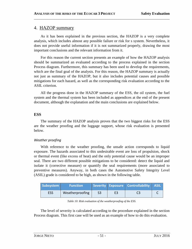
ANALYSIS OF THE RISKS OF THE ECOCAR 3 PROJECT Safety Evaluation
________________________________________________________________________
JORGE NIETO - 51 - JULY 2016
4. HAZOP summary
As it has been explained in the previous section, the HAZOP is a very complete
analysis, which includes almost any possible failure or risk for s system. Nevertheless, it
does not provide useful information if it is not summarized properly, drawing the most
important conclusions and the relevant information from it.
For this reason the current section presents an example of how the HAZOP analysis
should be summarized an evaluated according to the process explained in the section
Process diagram. Furthermore, this summary has been used to develop the requirements,
which are the final goal of the analysis. For this reason, the HAZOP summary is actually
not just as summary of the HAZOP, but it also includes potential causes and possible
mitigations for each hazard, as well as the corresponding risk evaluation according to the
ASIL criterion.
All the progress done in the HAZOP summary of the ESS, the oil system, the fuel
system and the thermal system has been included as appendices at the end of the present
document, although the explanation and the main conclusions are explained below.
ESS
The summary of the HAZOP analysis proves that the two biggest risks for the ESS
are the weather proofing and the luggage support, whose risk evaluation is presented
below.
Weather proofing
With reference to the weather proofing, the unsafe action corresponds to liquid
exposure. The hazards associated to this undesirable event are loss of propulsion, shock
or thermal event (like excess of heat) and the only potential cause would be an improper
seal. There are two different possible mitigations to be considered: detect the liquid and
isolate it (corrective measure) or quantify the seal requirements (more associated to
preventive measures). Anyway, in both cases the Automotive Safety Integrity Level
(ASIL) grade is considered to be high, as shown in the following table.
Subsystem Function Severity Exposure Controllability ASIL
ESS Weatherproofing S3 E3 C3 C
Table 10: Risk evaluation of the weatherproofing of the ESS.
The level of severity is calculated according to the procedure explained in the section
Process diagram. This first case will be used as an example of how to do this evaluation.
ANALYSIS OF THE RISKS OF THE ECOCAR 3 PROJECT Safety Evaluation
________________________________________________________________________
JORGE NIETO - 52 - JULY 2016
First of all, the level of severity of S3 corresponds to severe injuries. This level is
assigned in cases in which the failure or the issue analyzed is quite grave. In this case,
having a failure in the ESS would involve risk as severe as HV or fire, as it was explained
in the HAZOP analysis. For this reason, the severity is considered to be high. The other
two possibilities are S2 or medium severity, which corresponds to medium injuries, and
S1 or low severity, which means none or light injuries.
The second parameter is the probability of exposure. It evaluates the likelihood of the
undesirable event which is being analyzed. As it was explained in the corresponding
section, there are four different levels: very low, low, medium and high probability. In
this case the probability is considered to be medium (E3), meaning not too high but not
low either. Despite the protection, the ESS is always exposed and the weather proofing
might fail as it was explained in the analysis.
The last parameter is the controllability, which evaluates how difficult it is to deal
with the issue and whether it is possible to control it or not. There are three possible
levels of evaluation: simply controllable, normally and difficult to control. In this
example, once the ESS is damaged due to a failure in the weather proofing it would be
very difficult to control due to the risks that are associated to it, as explained in the
HAZOP analysis. Thus, the event is considered as difficult to control (C3).
Finally, the last step is determining the risk evaluation. This should be done
automatically, according to the criterion given in Table 5, in the section Process diagram.
In this case, the combination of these three parameters results in a high level of risk (C).
This same process is followed similarly with all the other elements and cases which
are considered in this section.
Luggage support
In this case, the unsafe event of the luggage support corresponds to a risk of HV
exposure. The hazards associated to this undesirable event are once again loss of
propulsion, shock or thermal event, whereas the potential causes can be that the ESS
housing is unable to support the weight of equipment and luggage or that ESS housing
seal fails under loading for any reason.
For the first cause there are two different possible mitigations. The first one would be
sticking warning labels with allowable loads visible to the user (preventive measure) and
second would be a design that guarantees that the ESS cover withstands 130kg in axial
loading. This same measure would mitigate the second cause (housing seal failure due to
the load).
The ASIL grade associated to these problems is defined as medium, as it is shown in
the Table 11.

ANALYSIS OF THE RISKS OF THE ECOCAR 3 PROJECT Safety Evaluation
________________________________________________________________________
JORGE NIETO - 53 - JULY 2016
Subsystem Function Severity Exposure Controllability ASIL
ESS Luggage support S3 E3 C2 B
Table 11: Risk evaluation of the luggage support of the ESS.
Once again, the level of severity corresponds to severe injuries (S3) and the
probability of exposure is medium (E3), while the event can be considered as normally
controllable (C2). In this case, the combination of these parameters results in a medium
risk (B).
Oil system
In this case the HAZOP analysis concludes that the oil system is not too risky, as all
the events that have been analyzed have been classified with the label Quality
Management (QM). In most of the cases, this has been the consequence of a low level of
severity (S1), a low probability (E2) and high difficulty of control (C3). Nevertheless,
despite this last parameter, the criterion establishes that the level of risk is still very low
(QM).
Fuel system
The HAZOP analysis in this case concludes that the most risky functionality for the
fuel system is the fire prevention, with a medium (B) evaluation.
The unsafe action related to this function is the possible fire ignition, which is a main
hazard for the vehicle. The potential causes are improper seal of the tank, the pipes or
other elements of the fuel system, or improper resistance to the environment (e.g. to high
temperatures). The measures for the mitigation could be ensuring proper seals around any
openings and connectors and installing flash arrestor (both of them can be considered as
preventive measures).
The severity, exposure and controllability assessment of this analysis are shown in
the Table 12.
Subsystem Function Severity Exposure Controllability ASIL
Fuel Fire prevention S3 E3 C2 B
Table 12: Risk evaluation of the fire prevention for the fuel system.
As it has been mentioned, The ASIL grade associated to this problem is medium (B),
having the same assessment explained for the case of the luggage support in the ESS for
the three parameters (severe injuries, medium probability of exposure and normal
controllability).

ANALYSIS OF THE RISKS OF THE ECOCAR 3 PROJECT Safety Evaluation
________________________________________________________________________
JORGE NIETO - 54 - JULY 2016
Thermal system
The HAZOP analysis in this case concludes that there are three different functions
with a higher importance in terms of safety, which are providing cooling to the ICE,
providing cooling to the transmission and the storage of the coolant. The three of them
have been assessed with an A according to the ASIL grade, which means low risk.
Provide cooling to ICE/transmission
The first two cases will be explained together, as the analysis is almost the same for
both of them.
The function of the thermal system in both cases is providing cooling, the unsafe
action is therefore not being able to remove enough heat and the resulting hazard is
damaging the component. Taking into account the importance of both the engine and the
transmission for the vehicle, having overheating in any of them would probably result in
a loss of propulsion. The only proposed measure is the installation of sensors to detect the
increase of temperature the sooner the better.
In both cases the Automotive Safety Integrity Level (ASIL) grade is considered to be
low, as shown in the following table.
Subsystem Function Severity Exposure Controllability ASIL
Thermal Provide cooling to
ICE/transmission S3 E2 C2 A
Table 13: Risk evaluation of the cooling of the ICE and the transmission in the thermal system.
The level of severity corresponds to severe injuries (S3), the probability of exposure
is low (E2) and the controllability can be considered as medium (C2).
Once again, the ASIL standard is applied for the combination of these three
parameters, resulting in a low level of risk (A).
Store coolant
In this case, the unsafe event is losing coolant from the system due to a leak or any
other cause. Due to the importance of the refrigeration for the correct functioning of some
key components, as the ones mentioned before, losing coolant could result in a loss of
propulsion. The potential causes can be an incorrect storage or sealing of the system and
a possible mitigation measure is installing baffles in the coolant tank.
The ASIL grade associated to these problems is defined as medium, as it is shown in
the Table 14.
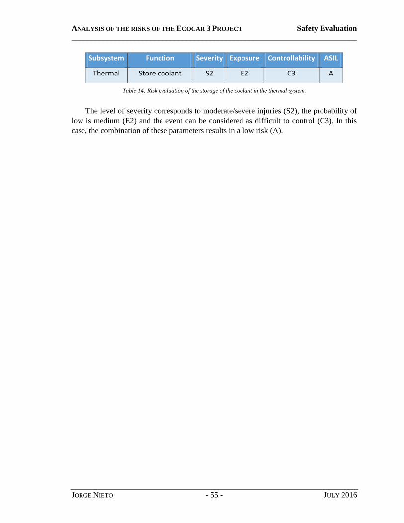
ANALYSIS OF THE RISKS OF THE ECOCAR 3 PROJECT Safety Evaluation
________________________________________________________________________
JORGE NIETO - 55 - JULY 2016
Subsystem Function Severity Exposure Controllability ASIL
Thermal Store coolant S2 E2 C3 A
Table 14: Risk evaluation of the storage of the coolant in the thermal system.
The level of severity corresponds to moderate/severe injuries (S2), the probability of
low is medium (E2) and the event can be considered as difficult to control (C3). In this
case, the combination of these parameters results in a low risk (A).

ANALYSIS OF THE RISKS OF THE ECOCAR 3 PROJECT Safety Evaluation
________________________________________________________________________
JORGE NIETO - 56 - JULY 2016
5. DFMEA
As it happened with the section Regulations, this part of the analysis was carried out
by other members of the team. The results of this analysis were also linked to the
requirements, but that work was done by those same members of the team and then just
supervised. For that reason, it will not be explained, but some parts of the analysis have
been included as an example in the section Appendices at the end of the document.

ANALYSIS OF THE RISKS OF THE ECOCAR 3 PROJECT Safety Evaluation
________________________________________________________________________
JORGE NIETO - 57 - JULY 2016
6. Requirements
The last step of the process of analysis consists in summarizing all the relevant
information from the results of the analysis with all the techniques and writing up formal
requirements that come from those conclusions.
A requirement is defined as a statement of what is wanted or what is to be
accomplished. These requirements have to be done in accordance with the regulations so
that each one of them has to be linked to any rule that is related directly or indirectly to it.
This connection will be done using the team´s classification, so that the numbered label
of each rule will refer to the label of the rule in the database of the team, as it was
explained in the section Regulations. Therefore, all the requirements will be classified in
a table in which three of the columns refer to one technique, another one refers to the
subsystem and the last one to the rule reference. Finally, there will be an empty column
that will be used to validate the requirements, following the process of the section
Process diagram.
Moreover, the requirements have to be written up according to the recommendations
provided in [26], respecting the framework given in terms of grammar and style. This
criterion proposes the following structure:
• Subject (Actor)
• Requirement Verb (“shall”)
• Action/Object
• Negotiated value
• Conditions
Taking into account that the writing of the requirements is the last task to be done by
the safety group it requires that all the previous parts are finished in advance. Therefore,
this will have to be done once all the previous analysis techniques have been applied.
However, the requirements for the ESS with the references of the HAZOP summary, the
DFMEA and the rules were done as an example of the methodology developed for this
thesis, so that they can be used as a model for the future. The requirements of the other
systems that have been analyzed in this document have also been started, but they cannot
be considered as finished and thus they will not be included.
For this reason, in this section, the process of how to write up a requirement will be
explained using only two examples from the requirements of the ESS, and the table with
all the requirements that were created for this system is included as an appendix at the
end of the document. These requirements that are used as an example for the explanation
are the REQ002 and the REQ014.

ANALYSIS OF THE RISKS OF THE ECOCAR 3 PROJECT Safety Evaluation
________________________________________________________________________
JORGE NIETO - 58 - JULY 2016
REQ002
The requirement number two has been written as follows:
“All parts exposed outside of the car shall be sealed against spills, rainwater, road
dust, and debris with a recommended minimum level of protection IP 56.”
This requirement has been defined according to the standard given by the Ingress
Protection ratings. This standard classifies and rates the degree of protection provided
against human intrusion (body parts such as hands and fingers), dust, accidental contact,
and water by mechanical casings and electrical enclosures. It is published by the
International Electrotechnical Commission (IEC) and its aim is to provide more detailed
information about sealing or weather proofing. The ranking is defined in accordance with
the test method defined in the standard [27].
According to this standard, the first digit of the IP code corresponds to the protection
against solid objects and the second corresponds to the protection against liquid object. In
the past there was also a third digit for the mechanical impact resistance, but nowadays is
no longer used in most cases. Furthermore, other optional protections, such as oil
resistance, can also be indicated with an additional letter at the end of the code
In this case, the level of protection IP 55 means the following levels of protection:
Protected against harmful dust.
No harmful effect of strong water jets from all direction.
Those levels have been considered as minimum requirements for a vehicle, taking
into account the normal use of a car. Obviously the higher the protection is the better for
the safety, but at least this minimum requirement would guarantee a reasonable level of
protection.
The first analysis to be related to this requirement is the HAZOP. As it was explained
in the corresponding section, the requirements are done the summary of the HAZOP,
which includes the assessment of the hazards.
This second requirement has been related to both the HAZSUM0001 and the
HAZSUM00002, which are the labels that refer the two first elements of the HAZOP
summary for the ESS. These two elements correspond to the waterproofing of the
function of the ESS, which was classified with a C level of riskiness. The reason of that
assessment is that the HAZOP analysis determined that liquid exposure could be really
dangerous for the ESS, so that it is very important to seal it properly. This can be
achieved by sealing all the outside parts of the car, as it is stated in the requirement.
With reference to the DFMEA analysis, the requirement has been related to the
DFMEA0009, whose failure mode is a ground fault. In that analysis it was determined
that the only current prevention was the isolation, and the level of riskiness was assessed
as very low (quality management).
ANALYSIS OF THE RISKS OF THE ECOCAR 3 PROJECT Safety Evaluation
________________________________________________________________________
JORGE NIETO - 59 - JULY 2016
Finally, as for the regulations, the requirement has to do with the RULE0062 (or the
NYSR I-1.2). According to the Rules table, this label refers to the following rule:
“All components used shall have appropriate ratings for the environments in which
they are used. The ratings include those for temperature, waterproofing, chemical
compatibility, etc.”
As it can be seen, the rule matches perfectly with the requirement.
REQ014
The requirement number fourteen states:
“Electrical connections between packs must contain mid-pack contactors to de-
energize the inter-pack HV cables during both normal shutdown and emergency
situations.”
First of all, with reference to the HAZOP summary the requirement was related to
the HAZSUM0010, which evaluates the risk of HV exposure in terms of user safety. In
that analysis, the mitigation was described as “All HV equipment shall be shrouded in
such a way that users cannot easily or accidently access HV risk areas” and the ASIL
level determined was an A (low).
As for the DFMEA, it corresponds to the DFMEA0012, which analyses the effect of
having over temperature. The issue was assessed with an ASIL level of QM (quality
management) and the only existing prevention was the internal detection. Even though it
does not refer directly with the requirement, the situation analyzed in that case can be
considered as an emergency situation which is risky for the electrical connection and thus
it has to do with it.
Finally, the requirement has been written up in accordance to both the RULE0106
and the RULE0107. The first one states that “The contactors shall be capable of
disconnecting the ESS from the HV bus under full-load current without part failure.”,
while the second one was summarized as “Each HV battery enclosure shall have
overcurrent protection in the form of a non-resetting current-limiting fuse connected in
series roughly halfway through the battery string.” So in this case both of the rules affect
directly the requirement and they both have to be included in the table.
ANALYSIS OF THE RISKS OF THE ECOCAR 3 PROJECT Comparative analysis
________________________________________________________________________
JORGE NIETO - 60 - JULY 2016
COMPARATIVE ANALYSIS
In order to give this thesis a bigger scope, it has been considered the possibility of
doing some research in the market to evaluate the results of the design of the team in
comparison with other real competitors. This section therefore transcends the initial scope
of this thesis, but it can be very useful to contrast the ERAU design.
Taking this into account, the purpose of this section will not be to provide a whole
detailed safety analysis of the hybrid vehicles of the market, but to do a basic comparison
of the car with other real competitors.
For this analysis, it has been decided to choose two different vehicles which can be
considered as direct competitors. On the one hand, the first car that is to be considered is
obviously the Chevrolet Camaro (the original version, without any extras or
modifications on the basic design). It is thought that any potential buyer of the ERAU
design would probably like the Camaro, so that it is important to know the main
differences in terms of safety between the original version and the design of the team.
On the other hand, as the vehicle would be hypothetically included in the hybrid
vehicles market, it is considered to be useful to compare its features with other cars on
this market. For this reason the second vehicle to be considered would be the Toyota
Prius, as it is one of the classic references of this market.

ANALYSIS OF THE RISKS OF THE ECOCAR 3 PROJECT Comparative analysis
________________________________________________________________________
JORGE NIETO - 61 - JULY 2016
1. Original Chevrolet Camaro
First of all, in order to do a proper comparison it has to be borne in mind that there
are several different models for the Chevrolet Camaro. For this section the general name
of “Original Chevrolet Camaro” has been used mainly to make a difference between the
models that can be found in the market and the design of the team. However there are
many different vehicles with different features and performance that are still a Chevrolet
Camaro, and each of them can include some extras which affects their performance.
For this reason, the first comment is that the only vehicles to be considered are the
newest versions, so that all the models previous to 2016 are not reviewed. After some
research, it has been determined that there are two of the models of the Camaro 2016 that
have similar specifications and could be good examples competitors if the design of the
team was in the market. Those vehicles are:
2016 Camaro SS convertible [W6].
2016 Camaro V6 Manual [W7].
Obviously, these two vehicles are still totally different from the model that is being
designed, as they are not HEVs. Besides, the Camaro is a sports car and thus the
performance is the most important thing for the brand. This means that these models are
still far from being eco-friendly, so that they are very different from any kind of hybrid
car. Anyway, some of their features are relatively similar to the design of the team, as it is
shown in the Table 15.
For this comparative table most of the specifications of the V6 Manual were not
found, so that most of the features in the table belong to the closest model, which is the
2016 Camaro 2.0T Manual (the V6 is indeed an advance version of the car with higher
performance, but with the same kind of design).
Specifications 2016 Camaro SS convertible
2016 Camaro 2.0T Manual (V6)
EcoEagles Design (LEA Parallel Series-A)
Acceleration, 0-60 mph
4.1 sec 5.4 (5.1) sec 4.9 sec
Top Gear, 50-70 mph
2.8 sec 11.3 sec 3.7 sec
Lateral acc., 300 ft skid pad
0.96 g 0.89 g 0.95 g
CD Range 18 mi 19 mi 36.2 mi
Braking, 70-0 mpg
170 ft 152 ft 120 ft (60-0 mph)*
Table 15: Basic features of some models of the Chevrolet Camaro.

ANALYSIS OF THE RISKS OF THE ECOCAR 3 PROJECT Comparative analysis
________________________________________________________________________
JORGE NIETO - 62 - JULY 2016
With reference to safety issues, the problem is the same. Each model has its own
specifications and therefore the analysis would be complex. Nevertheless, as it has been
explained the aim of this section is just to present some basic information so that it can be
used as the base for a whole new study. For this reason, the main safety features of any
kind of 2016 Chevrolet Camaro are going to be presented below as the basis any further
research and analysis. These features are the following [W8]:
Anti-lock brakes: all the vehicles have ABS brakes that automatically detect when
a tire has stopped rotating under extreme braking, and will modulate the brake
pressure to allow the tire to rotate. This feature increases the vehicles ability to
turn while braking.
Stability control: this system automatically senses when the vehicles handling
limits have been exceeded and reduces engine power and/or applies select brakes
to help prevent the driver from losing control of the vehicle.
Front-impact airbags: the front airbags have been designed to protect the head of
the driver and front passenger in case of a frontal crash.
Side impact airbags: they are used in the front seats to protect the trunk during a
side impact collision.
Overhead airbags: these airbags are designed to protect the occupant's heads in the
event of rollover.
Knee airbags: Knee airbags help to protect the occupants‟ lower extremities from
serious injuries in case of accident.
Pretensioners: seatbelt pretensioners automatically tighten seatbelts to place the
occupant in the optimal seating position during a collision.
Security system: each Camaro is equipped with a safety system that anticipates
and/or detects unwanted vehicle intrusion. The vehicle is also equipped with an
ignition disable device that will prevent the engine from starting if the correct
original manufacturer key is not used. This protection ensures that a potential thief
is not able to run the vehicle without the key.
These features are only some examples of the safety equipment of the 2016
Chevrolet Camaro. Studying them in advance and contrasting the impact of the new
components of the design of the team is proposed as a topic for future research.

ANALYSIS OF THE RISKS OF THE ECOCAR 3 PROJECT Comparative analysis
________________________________________________________________________
JORGE NIETO - 63 - JULY 2016
2. Toyota Prius
With no doubt, Toyota has always been one of the leaders of the market of hybrid
vehicles since it started. The brand is committed to the development of new vehicles with
better and better performance based on HEV technology.
In the same direction, the Toyota Prius is the most iconic HEV of the company,
being probably one of the leading vehicles in the whole market from the very beginning.
The Proius is still the sales leader of full HEVs and each new version of the car is having
a good reception in the market.
For this reason, it is thought that the 2016 Toyota Prius would be a good reference to
contrast the specifications of the EcoEagles Camaro with the real market.
Figure 17: Toyota Prius, the most popular Full HEV of all time.
Nevertheless, it has to be taken into account that the Toyota Prius and the Chevrolet
Camaro are two vehicles which are completely different from any perspective. On the
one hand, the Toyota Prius is a pure hybrid vehicle, whose purpose has always been
focused on having a low consumption and emissions. The performance is still important,
but it is not one of the priorities for design.
On the other hand, the EcoEagles Camaro is a sports car that has been modified and
turned into a hybrid car. But it is still a sports vehicle and the performance matters. For
this reason, it is to be expected that some of the features related to performance are going
to be higher (horsepower, acceleration, torque or top speed), which means that most
likely the efficiency cannot be as high as in the Prius.

ANALYSIS OF THE RISKS OF THE ECOCAR 3 PROJECT Comparative analysis
________________________________________________________________________
JORGE NIETO - 64 - JULY 2016
However, it still has an eco-friendly design, and it can be competitive in that market
as some of the features show. For instance, whereas the Prius Two Eco offers a quite
impressive fuel economy with its EPA-estimated 58 mpg city [W9], the EcoEagles
design has an EPA-estimated of 53.0 mppge, which is just slightly lower than the Prius
and still very high for a sports car.
In terms of safety, the Toyota Prius is also a leading vehicle. As it was done with the
Camaro, some of the most interesting safety features are explained below. First of all, it
has two safety packs with several different features, which are the following:
Star Safety System: Prius comes standard with the Star Safety System™
, a suite of
six advanced safety features that includes enhanced Vehicle Stability Control
(VSC), Traction Control (TRAC), Anti-Lock Brake System (ABS), Electronic
Brake-force Distribution (EBD), Brake Assist (BA) and Smart Stop Technology
(SST).
Toyota Safety Sense: is an active safety package that combines the Pre-Collision
System with Pedestrian Detection (PCS w/PD), Lane Departure Alert with
Steering Assist (LDA w/SA), Auto High Beams (AHB) and Full-Speed Dynamic
Radar Cruise Control (DRCC) to assist the driver. These comprehensive features
create in-the-moment safety designed to support the driver‟s awareness and
decision-making on the road.
Furthermore, it includes some innovative features, which are thought to help the
driver when running the car. Once again, the reader is invited to do some more research
on the comparison of these features with the EcoEagles design.
Blind Spot monitor: if a vehicle is detected in the blind spot, the available Blind
Spot Monitor (BSM) system alerts the driver through an illuminated indicator on
the appropriate side mirror.
Rear Cross-Traffic alert: this system is designed to provide an audible indicator to
help warn the driver of approaching vehicles in case he/she is baking out a
driveway or parking spot.
Integrated backup camera: it helps the driver by giving him/her a view of what the
camera detects from the rear. This feature is especially useful when you‟re
parking in a tight spot or backing up.
Rain-sensing windshield wipers: they are designed to automatically adjust to
match the amount of rain hitting the windshield and the speed of the vehicle.
ANALYSIS OF THE RISKS OF THE ECOCAR 3 PROJECT Results
________________________________________________________________________
JORGE NIETO - 65 - JULY 2016
RESULTS
The results of this project correspond with the performance of the team in the
competition. It is true that the thesis has its own scope within the goals of the Safety
group, but at the end the main purpose is to help the team to achieve their objectives and
hopefully win the whole competition. For that reason, the best way to measure the
successfulness of the thesis is contrasting the results of the whole team both in the second
year of the competition, and also at the end of the four years (as one of the goals is that
all this research and work can be useful for future members and used in order to continue
with all the tasks).
Obviously, the final results of the competition will be known long after this
document is presented, but the results of the second year have already been determined
by the judges of the competition and are presented below.
Apart from that, this section also presents the most important results of the analysis
that has been already carried out, in order to summarize the most relevant information.
These results are not decisive yet, because some parts of the analysis might change in the
coming years, but they are still useful to summarize the work done for this thesis.

ANALYSIS OF THE RISKS OF THE ECOCAR 3 PROJECT Results
________________________________________________________________________
JORGE NIETO - 66 - JULY 2016
1. Relevant results of the analysis
As it has been explained in the corresponding part of the document, the HAZOP
analysis can be considered as the main task within this thesis. For this reason, this section
presents the main results of this analysis, which are mainly those who have been proved
to be more risky. Those results are summarized in the table below.
Subsystem Function Risk evaluation Mitigation measures
ESS Weatherproofing High (C)
- Detect the liquid and isolate it (corrective measure).
- Seal requirements (prevention).
ESS Luggage support Medium (B)
- Sticking warning labels with allowable loads visible to the user (preventive measure).
- Guaranteeing that the ESS cover withstands 130kg in axial loading (design).
ESS Module support Low (A) - A safety factor of 1.5 in the structure is required.
ESS User safety Low (A)
- Proper enclosure of dangerous parts.
- Providing procedures for safety access and maintenance.
Fuel Fire prevention Medium (B)
- Ensuring proper seals around any openings and connectors.
- Installing flash arrestor.
Fuel Puncture resistance
(fuel leaks) Low (A)
- Measuring the puncture resistance.
- Sealing the system properly.
Fuel Mounting Low (A)
- Designing according to the requirements (8g resistance to vertical static load and 20g to longitudinal and lateral static load plus a factor of safety of 1.5).
Thermal Provide cooling to ICE/transmission
Low (A) - Installing temperature sensors.
Thermal Store coolant Low (A) - Baffles in the coolant tank
- Proper sealing of the system.
Table 16: Main results of the analysis.

ANALYSIS OF THE RISKS OF THE ECOCAR 3 PROJECT Results
________________________________________________________________________
JORGE NIETO - 67 - JULY 2016
Although this table presents the result of the analyses of the most risky components
and functions of each of the systems, it has to be taken into account that there are also
other parts that are important despite being less risky. For instance, the functioning of the
oil system taken as a whole is essential for the car, even though in the results of the
HAZOP analysis none of the functions have a high level of riskiness according to the
ASIL evaluation.
Moreover, it should be born in mind that one of the main tasks of this thesis was
developing a methodology that could be used systematically to carry on more analyses
during the coming years. This methodology has been developed and used, but it cannot
be considered as a result itself. For this reason, the results that are presented in the table
cannot be considered as a summary of the whole thesis, but just as the results of the
analysis.
Anyway, the process of analysis and the methodology that has been presented in this
document was also explained in the competition as it was one of the requirements for the
second year and they will be commented in the conclusions.

ANALYSIS OF THE RISKS OF THE ECOCAR 3 PROJECT Results
________________________________________________________________________
JORGE NIETO - 68 - JULY 2016
2. Competition
2.1. Results of the Safety Systems group (end of Y2)
The result of the Systems Safety group could not have been more successful, as the
team ended up being the winners of Y2 competition.
According to this decision, the level of satisfaction with the result of this thesis is
high. As it has been said before, there were several people working within the Safety
Systems section, so that the sole contribution of this work would be nothing without the
effort of all the other members of the team, with a special mention for Ben Coleman, as
the leader of the group. But anyway it is also a personal motivation, as the goal has
always been that this work was useful to help the group meet its expectations and achieve
a good result.
2.2. Overall results of the ERAU team (end of Y2)
Third Place Overall EcoCAR 3, Year 2
Excellence in Leadership - Thomas Gorgia (EcoEagles Engineering Manager)
Best Charge Depleting Mode
Best Overall Safety Tech
Best Skidpad Performance
Best Systems Safety
Best Functional Vehicle Safety
Best Vehicle Design Review
Best Skit Video
Spirit of Project Management
Third Place for National Science Foundation (NSF) Innovation Award
Sportsmanship Award
TRC Award (Two weeks at TRC with our car, full emissions testing, and a
proving ground JUST for our team, in October)
In the end, the ERAU won the competition. However, the team was facing a 50 point
deficit from pre-competition deliverables. For this reason, it ended up finishing
3rd overall, 4 points behind Virginia Tech and 15 points behind Ohio State (out of 1000).
ANALYSIS OF THE RISKS OF THE ECOCAR 3 PROJECT Conclusions
________________________________________________________________________
JORGE NIETO - 69 - JULY 2016
CONCLUSIONS
The conclusions of this thesis have been organized in three different categories,
which basically correspond to the results, the usefulness of the methodology developed
and the attainment of the objectives that were stated in the beginning.
First of all, the conclusions of the analysis are commented, explaining a bit more
which the most relevant results of the analysis are. Thus, this first part has to do with the
technical side of the work, being an attempt to point out the most important conclusions
of it.
Secondly, the validation of the methodology is presented, explaining its usefulness
and advantages and disadvantages. In this part, the concept of “methodology” refers both
to the process followed throughout the whole thesis and the methodology of analysis that
has been developed with the techniques that are used for it.
Finally, the objectives that were set at the beginning of the thesis are contrasted with
the actual work done and the results obtained. The idea is to prove if the goals have been
met or not, as well as to explain the degree of satisfaction with the work done.

ANALYSIS OF THE RISKS OF THE ECOCAR 3 PROJECT Conclusions
________________________________________________________________________
JORGE NIETO - 70 - JULY 2016
1. Conclusions of the analysis
First of all, it has to be mentioned once again that the conclusions are just drawn
from the parts of the analysis that have been carried out yet. This means that they are not
definitive for the team or the design, but just relevant comments that come from the
results of the analyses that have been done so far.
From those existing results, the first relevant conclusion that is observed is that the
actual degree of riskiness obtained in most cases in quite low according to the standards.
However, some of the undesired events that have been analyzed are extremely dangerous
and the consequences would be very severe in case they occur. But it has to be taken into
account that the severity is not the only parameter that counts for the risk evaluation. The
likelihood of the event and its controllability are also equally important to assess a risk
according to the aforementioned ASIL standard.
For this reason, some of the components that have a key role for the correct
functioning of the car actually have a level of riskiness which is lower than what it could
be expected. The only reason for that result is thus that the probability of failure in the
subsystem or the component is quite low, the controllability is reasonable or a
combination of both.
Anyway, most of the events that have been analyzed have a level of risk which is
low (A) or very low (QM, e.g. quality management), as it can be seen in the table below.
Risk evaluation QM A B C D To be determined
Percentage 38,9% 44,4% 11,1% 5,6% 0,0% 5,6%
Table 17: Frequency of each level of riskiness according to the ASIL standard.
Furthermore, the results can be analyzed by subsystems of the vehicle to determine
which one is the most dangerous. In order to do this comparison, the average riskiness of
each subsystem has been calculated according to a numerical scale in which each of the
levels of riskiness has been given a value from 1 to 5, as it is shown in the table below.
Level Numerical value
QM 1
A 2
B 3
C 4
D 5
Table 18: Correlation between each level of riskiness and its numerical value..
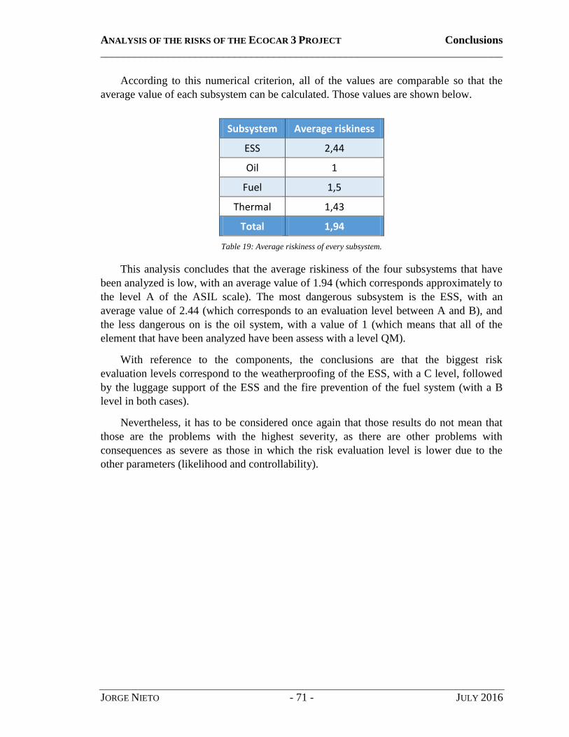
ANALYSIS OF THE RISKS OF THE ECOCAR 3 PROJECT Conclusions
________________________________________________________________________
JORGE NIETO - 71 - JULY 2016
According to this numerical criterion, all of the values are comparable so that the
average value of each subsystem can be calculated. Those values are shown below.
Subsystem Average riskiness
ESS 2,44
Oil 1
Fuel 1,5
Thermal 1,43
Total 1,94
Table 19: Average riskiness of every subsystem.
This analysis concludes that the average riskiness of the four subsystems that have
been analyzed is low, with an average value of 1.94 (which corresponds approximately to
the level A of the ASIL scale). The most dangerous subsystem is the ESS, with an
average value of 2.44 (which corresponds to an evaluation level between A and B), and
the less dangerous on is the oil system, with a value of 1 (which means that all of the
element that have been analyzed have been assess with a level QM).
With reference to the components, the conclusions are that the biggest risk
evaluation levels correspond to the weatherproofing of the ESS, with a C level, followed
by the luggage support of the ESS and the fire prevention of the fuel system (with a B
level in both cases).
Nevertheless, it has to be considered once again that those results do not mean that
those are the problems with the highest severity, as there are other problems with
consequences as severe as those in which the risk evaluation level is lower due to the
other parameters (likelihood and controllability).

ANALYSIS OF THE RISKS OF THE ECOCAR 3 PROJECT Conclusions
________________________________________________________________________
JORGE NIETO - 72 - JULY 2016
2. Methodology validation
As it has been explained in other sections of the document, the development of a
methodology of analysis that could be used for the current and future safety analyses of
the team was one of the main tasks of this thesis. For this reason, there are some
conclusions that can be drawn from that process, and the purpose of this section is thus
the validation of that work of research and development.
In order to evaluate the analysis method properly, there are some characteristics that
are especially relevant. Those features are explained below.
Completeness
The first parameter to be considered for a proper validation is the completeness,
which evaluates how complete the methodology and the analyses are.
Obviously, it does not exist a method of analysis which is able to cover a system
as complex as a car in its entirety. In this sense there is always room for
improvement, because the more analyses are carried out the more complete the
process would be.
However, this methodology proposes the use of one method of analysis from each
of the most common approaches (deductive, inductive and exploratory). Thus, the
combination of the three of them results in a very complete safety evaluation.
Furthermore, these analyses are respectful with the regulations and have been
pointed towards the requirements of the competition. For these reasons, the
degree of completeness is considered to be more than enough.
Versatility
One of the most important features of a process of analysis is the possibility of
using it for many different components and subsystems. Logically, each kind of
analysis adapts for some elements better than for others, but it would not be useful
to choose a different method for each case.
Therefore, it is more organized to develop a method that can be applied in
multiple situations with a reasonably high degree of accuracy, so that the process
is consistent. This is another reason why using three different approaches
simultaneously is an advantage, as it allows it to be used for almost any kind of
component.
On the other hand, it is true that this methodology has been developed for a safety
analysis and thus would not be so useful in other kinds of studies.

ANALYSIS OF THE RISKS OF THE ECOCAR 3 PROJECT Conclusions
________________________________________________________________________
JORGE NIETO - 73 - JULY 2016
Usefulness
Although this feature looks obvious, it still has to be considered. Basically it
evaluates whether the methodology is useful or not.
The conclusion in this case is simple: the analyses are being carried out and the
safety group is getting real results from them, therefore the methodology is useful
for the team.
Complexity
The complexity of a method is not necessarily positive or negative by itself, but it
depends on the needs of the system analyzed and the degree of profoundness that
wants to be achieved. Obviously, developing a complex method is not desirable as
an objective, but in most cases some degree of complexity is required to have
results with enough level of detail.
In this case, the study is not extremely difficult to be done, but it is long, detailed
and requires a group of people working on it. As it has been explained, some of
the techniques are based on discussing each component and subsystems in several
meetings with the members of the team. This has the disadvantage that it does not
allow real progress when someone wants to works on its own, and it requires the
availability of a minimum number of three or four people for the meetings. It
involves a lot of cooperation and all the results have to be organized
systematically with a clear criterion so that other members can use it, review it or
keep on working.
On the other hand, it has the advantage of having multiple perspectives and points
of view in each of the analysis. Besides, taking into account that the number of
ERAU students working on this is quite large, it allows that there is work for
everybody and that new students can join in the future and learn how to do it. But
for this being possible everything has to be organized, which is the most difficult
task of the team for succeeding.
Validity
This last feature would be indeed a combination of all the others. The final
purpose of this section is to prove that the methodology is valid for the safety
evaluation of the vehicle.
According to the progress done throughout this second year and the results
obtained, it seems that the method of analysis is working. The study is reasonably
complete, systematic and versatile at the same time, and it has enough level of
detail. Moreover, the ERAU safety team has achieved the first position of this
second year of competition, which confirms the validity of the method developed.

ANALYSIS OF THE RISKS OF THE ECOCAR 3 PROJECT Conclusions
________________________________________________________________________
JORGE NIETO - 74 - JULY 2016
3. Attainment of objectives
The goal of this last part of the conclusions is contrasting the original objectives of
the thesis with the actual results.
The first one of the objectives was the previous study and basic knowledge of the
design of the team for the EcoCAR 3 Project. This involved the understanding of the
architecture, the main components and the different modes of operation as well as the
risks of using either the electric motors or the gasoline engine.
This phase of review was carried out in the first part of the document. The degree of
profoundness of this study was not too high due to the time limitations and the
complexity of the design as a whole. Anyway, the objective of having a basic knowledge
on the vehicle and the design can be considered to be achieved, including those parts that
have not been included in the analyses yet.
Nevertheless, the part of dealing with the responsible of every area of the team was
modified, as it was not necessary to have those meetings in this first stage of the safety
evaluation. Probably in the next two years the importance of the changes in the design of
each subsystem will be bigger and bigger. For this reason, it is expected to have regular
meetings between the future responsible of the safety team and each of the responsible of
the biggest areas of the project, in order to evaluate the impact of any modification in the
safety analyses.
With reference to the analysis it can be concluded that the team is working on the
right track. It was considered to be an objective giving consistent alternatives for the
designs with the high potential hazard as well as preventive and corrective measures for
the main problems analyzed and the section of requirements is aimed to focus on this
goal. As it has been said before the process is still in their first stages, but in the future the
team will have to keep on doing an effort on this. The objective is not only to detect the
main hazards, but also to provide reasonable alternatives.
Finally, the last objective was to explain the methodology to other students so that
they can continue working on safety issues in the future. This last part has been highly
emphasized, as having a consistent approach that can last during the rest of the
competition is considered to be one of the keys for s for the team to succeed.
For all these reasons, the level of satisfaction with the work done is quite high. The
main objectives of the thesis have been attained and the good results in the competition
confirm the validity of the safety evaluation methodology. These results should
encourage the team to keep on working with the same effort in the future, so that they can
end up the competition in the first positions and, above everything, develop a competitive
vehicle with high safety standards.

ANALYSIS OF THE RISKS OF THE ECOCAR 3 PROJECT Future work
________________________________________________________________________
JORGE NIETO - 75 - JULY 2016
FUTURE WORK
As this is just the second year of competition, there is still plenty of work to be done
by the team. The results of the competition have proved that ERAU is in the right track,
both the whole team and the Safety Systems group in particular. However, there are two
more years of competition in which the team will have to keep the effort to be able to
succeed at the end.
Obviously, the Safety group will keep on working after the end of this thesis, and
they know what they have to do to keep this great performance. For this reason, the
possibilities that are presented in the current section are just a summary of the tasks for
the following two years together with some ideas, which I personally think that could be
useful as a complement for the safety analysis.

ANALYSIS OF THE RISKS OF THE ECOCAR 3 PROJECT Future work
________________________________________________________________________
JORGE NIETO - 76 - JULY 2016
1. Improvements and further analysis
Most of the work done so far is not complete yet. Therefore, this means that the team
will have to keep on working on this analysis and apply them in every single subsystem
within the car.
Furthermore, there are two factors that will probably require improvements and
changes in the analysis that have been done so far.
Changes in the designs: this is just the end of the second year of competition,
which means that this is only half of the way. For this reason, some designs on
several subsystems are still likely to be changed, and this will affect the safety
analyses that have been done on them.
Results for the tests: the engineers of the team carry out tests on the car frequently
and those tests are the base for the new designs and improvements. However,
those tests can be also useful in terms of safety because most of the analysis has
been done theoretically and therefore it is important to bear in mind that real
systems‟ behavior can differ from what is expected in theory.
Anyway, apart from these two factors, the analyses that have been done still require a
higher level of depth if the team wants to achieve the same success in the future.
ANALYSIS OF THE RISKS OF THE ECOCAR 3 PROJECT Future work
________________________________________________________________________
JORGE NIETO - 77 - JULY 2016
2. New analysis techniques
One of the three techniques that has been presented in the review section, the FTA
method, has not been applied yet, as it is already within the plans of the Safety group. For
this reason, this will probably be the first new analysis technique to be used in the future.
However, it is not the only possibility, as there are more techniques that have not
been considered and that could be probably equally useful to provide a more complete
Safety analysis. Keeping the same methodology and procedures, the following two kinds
of analysis are two examples of new techniques that could be used in the future.
Inductive: Interface analysis.
An interface is defined as a shared boundary or connection between two
components. As most systems, the car designed by the ERAU team require
connections, which are normally one of the most likely reasons of a failure in any
system. The interface analysis is a business analysis technique that helps to
identify interfaces between solutions/applications to determine the requirements
for ensuring that the components interact with one another effectively [W10].
For this reason, despite being a business analysis technique, this method could be
very useful to study the interaction of different components of the car and to
analyze how to ensure that they interact as they should.
Exploratory: what-if analysis.
The what-if analysis is an exploratory technique that consists of analyzing the
impact of a hypothesis on the functioning of any system. The methodology is
similar to the HAZOP analysis, as it considers possible undesired situations of
each subsystem and analyzes the hazards and the possible causes that are
associated to the problem.
This kind of analysis can be considered as a complement of the HAZOP and
would be useful to double-check the results of that analysis, as well as finding
new components and subsystems that are important in terms of safety.

ANALYSIS OF THE RISKS OF THE ECOCAR 3 PROJECT Future work
________________________________________________________________________
JORGE NIETO - 78 - JULY 2016
3. Other fields of analysis
Although they are beyond the scope of the Safety Group, there are other possible
fields of research that are related to the safety analysis of the EcoCAR 3 Project and they
are therefore very interesting in order to do a full realistic research on this topic. Those
new branches of analysis are not meant to be an improvement on the existent work, but as
whole new topics which could be used for future research or even future graduate thesis
for those who want to take a step forward on it. Three of this examples are presented
below.
3.1. Analysis of the risks of the competition itself
The first possibility could be considered as an analysis within the analysis. Due to
the success of the team at the end of year 2 there are plenty of risks that will have to be
face if they want to achieve the same success at the end and win the whole competition.
There are several risks that can prevent ERAU from this, as the examples mentioned
below:
Lower level of motivation due to the good results.
Loss of key members of the team that will graduate before the end of the
competition.
Not being able to build major improvements on what has been done so far.
Even if ERAU stays on the right track there are other teams that are likely to increase
the effort towards the end, which is also a potential risk.
For all these reasons, this is an analysis that could be done with more details and that
could be also used as a motivation for the team in the future.
3.2. Comparative safety analysis with other competitors
Although there is an introduction for this field in one of the sections, there is still
plenty of work to do, so that this would be an interesting topic to be analyzed in detailed
in the future.
The analysis could include more cars and more features, and could be based on
different criteria, such as safety or performance of each of the vehicles. Therefore, there
are a lot of opportunities for future research in this field.

ANALYSIS OF THE RISKS OF THE ECOCAR 3 PROJECT Future work
________________________________________________________________________
JORGE NIETO - 79 - JULY 2016
3.3. Study of the risks of the market and future viability of the car
In this case, the term „risk‟ gets a new meaning, as it will involve economic analysis
and viability. However this is still a very important field to be considered if the ERAU
design would ever want to be taken to a bigger level, from college to the real world.
Besides, this can be a perfect complement for the previous field, as the analysis of
the market will be based on the features of the competitors that would have been already
studied.

ANALYSIS OF THE RISKS OF THE ECOCAR 3 PROJECT References
________________________________________________________________________
JORGE NIETO - 80 - JULY 2016
REFERENCES
1. Bibliography
[1] Argonne National Laboratory, EcoCAR 3 Non-Year-Specific Rules (revision: F), U.S.
Department of Energy, December 2015.
[2] Argonne National Laboratory, EcoCAR 3 Year Two Event Rules (revision: D), U.S.
Department of Energy, February 2016.
[3] EcoCAR 3 ERAU Team, Feasibility Study Report, Embry-Riddle Aeronautical
University, December 2014.
[4] EcoCAR 3 ERAU Team, Architecture Selection, Embry-Riddle Aeronautical
University, February 2015.
[5] Clemens, Pat L., and Simmons, Rodney J, System Safety and Risk Management, U.S.
Department of Health and Human Services, March 1998.
[6] Glancey, Jim, Failure Analysis Methods, Special Topics in Design, University of
Delaware, 2006.
[7] FAA System Safety Handbook, 2000.
[8] NEBOSH National Diploma - Unit A | Managing Health and Safety, 2010.
[9] Morris, Mark A., Failure Mode and Effects Analysis, ASQ Automotive Division
Webinar, November 2011.
[10] Carlson, Carl S., Effective FMEAs, John Wiley & Sons, 2012.
[11] Devos, Denis J., Design Failure Modes and Effect Analysis, Devos Asociates Inc.,
University of Western Ontario, 2012.
[12] University of Calgary (public doc), Failure Modes & Effects Analysis.
[13] Gelman, Andrew, Exploratory Data Analysis for Complex Models, Department of
Statistics and Department of Political Science, Columbia University, 2004.
[14] Rausand, Marvin, HAZOP Hazard and Operability Study, Norwegian University of
Science and Technology, October 2005.
[15] New South Wales Department of Planning, HAZOP Guidelines, NSW Government,
January 2011.

ANALYSIS OF THE RISKS OF THE ECOCAR 3 PROJECT References
________________________________________________________________________
JORGE NIETO - 81 - JULY 2016
[16] United Nations Environment Programme (UNEP), Hybrid Electric Vehicles: An
overview of current technology and its application in developing and
transitional countries, September 2009.
[17] National Renewable Energy Laboratory (NREL), Vehicle Technologies Program,
U.S. Department of Energy, October 2011.
[18] Duoba, Mike, Engine Design, Sizing and Operation in Hybrid Electric Vehicles,
Argonne National Laboratory, U.S. Department of Energy, June 2011.
[19] Li, Grace, et al., How can we encourage local communities to invest in hybrid cars?,
slideshare.net, Julio 2008.
[20] Gover, James, A Tutorial on Hybrid Electric Vehicles: EV, HEV, PHEV and FCEV,
IEEE Fellow Professor of Electrical Engineering, Kettering University, January
2016.
[21] Miller, John M., Propulsion systems for hybrid vehicles, IEE Power & Energy
Series, 2004.
[22] SAE International, Surface Vehicle Information Report, November 2010.
[23] Bradley, Tom, and Stanton, Ken, Hybrid Electric Vehicle Architectures, Colorado
State University, July 2012.
[24] Vernacchia, Mark, System Safety Deep Dive, GM Technical Fellow, Argonne
National Laboratory – U.S. Department of Energy, October 2015.
[25] International Standard, ISO 26262-9: Automotive Safety Integrity Level (ASIL)
oriented and safety-oriented analysis, November 2011.
[26] Vernacchia, Mark and Popma, Lynette, System Safety Process Overview, GM
Technical Fellow, Argonne National Laboratory – U.S. Department of Energy,
January 2016.
[27] IEC Standard 60529, Ingress Protection Ratings, Omron, 2001.
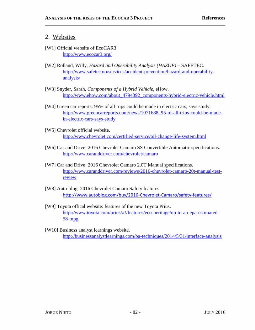
ANALYSIS OF THE RISKS OF THE ECOCAR 3 PROJECT References
________________________________________________________________________
JORGE NIETO - 82 - JULY 2016
2. Websites
[W1] Official website of EcoCAR3
http://www.ecocar3.org/
[W2] Rolland, Willy, Hazard and Operability Analysis (HAZOP) – SAFETEC.
http://www.safetec.no/services/accident-prevention/hazard-and-operability-
analysis/
[W3] Snyder, Sarah, Components of a Hybrid Vehicle, eHow.
http://www.ehow.com/about_4794392_components-hybrid-electric-vehicle.html
[W4] Green car reports: 95% of all trips could be made in electric cars, says study.
http://www.greencarreports.com/news/1071688_95-of-all-trips-could-be-made-
in-electric-cars-says-study
[W5] Chevrolet official website.
http://www.chevrolet.com/certified-service/oil-change-life-system.html
[W6] Car and Drive: 2016 Chevrolet Camaro SS Convertible Automatic specifications.
http://www.caranddriver.com/chevrolet/camaro
[W7] Car and Drive: 2016 Chevrolet Camaro 2.0T Manual specifications.
http://www.caranddriver.com/reviews/2016-chevrolet-camaro-20t-manual-test-
review
[W8] Auto-blog: 2016 Chevrolet Camaro Safety features.
http://www.autoblog.com/buy/2016-Chevrolet-Camaro/safety-features/
[W9] Toyota offical website: features of the new Toyota Prius.
http://www.toyota.com/prius/#!/features/eco-heritage/up-to-an-epa-estimated-
58-mpg
[W10] Business analyst learnings website.
http://businessanalystlearnings.com/ba-techniques/2014/5/31/interface-analysis
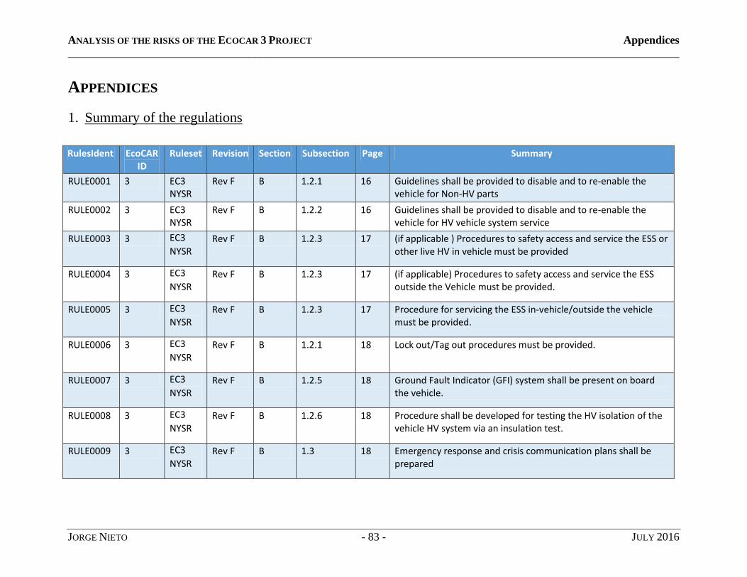
ANALYSIS OF THE RISKS OF THE ECOCAR 3 PROJECT Appendices
____________________________________________________________________________________________________________
JORGE NIETO - 83 - JULY 2016
APPENDICES
1. Summary of the regulations
RulesIdent EcoCAR ID
Ruleset Revision Section Subsection Page Summary
RULE0001 3 EC3 NYSR
Rev F B 1.2.1 16 Guidelines shall be provided to disable and to re-enable the vehicle for Non-HV parts
RULE0002 3 EC3 NYSR
Rev F B 1.2.2 16 Guidelines shall be provided to disable and to re-enable the vehicle for HV vehicle system service
RULE0003 3 EC3
NYSR Rev F B 1.2.3 17 (if applicable ) Procedures to safety access and service the ESS or
other live HV in vehicle must be provided
RULE0004 3 EC3
NYSR Rev F B 1.2.3 17 (if applicable) Procedures to safety access and service the ESS
outside the Vehicle must be provided.
RULE0005 3 EC3
NYSR Rev F B 1.2.3 17 Procedure for servicing the ESS in-vehicle/outside the vehicle
must be provided.
RULE0006 3 EC3
NYSR Rev F B 1.2.1 18 Lock out/Tag out procedures must be provided.
RULE0007 3 EC3
NYSR Rev F B 1.2.5 18 Ground Fault Indicator (GFI) system shall be present on board
the vehicle.
RULE0008 3 EC3
NYSR Rev F B 1.2.6 18 Procedure shall be developed for testing the HV isolation of the
vehicle HV system via an insulation test.
RULE0009 3 EC3
NYSR Rev F B 1.3 18 Emergency response and crisis communication plans shall be
prepared
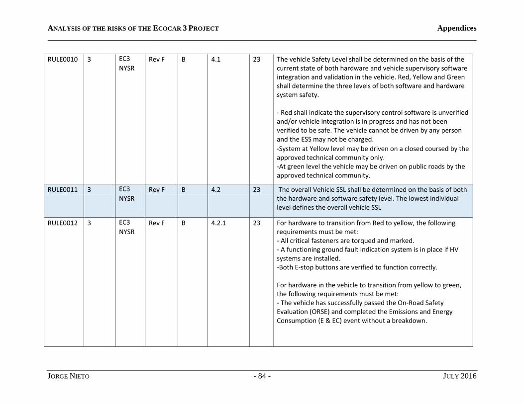
ANALYSIS OF THE RISKS OF THE ECOCAR 3 PROJECT Appendices
____________________________________________________________________________________________________________
JORGE NIETO - 84 - JULY 2016
RULE0010 3 EC3
NYSR Rev F B 4.1 23 The vehicle Safety Level shall be determined on the basis of the
current state of both hardware and vehicle supervisory software integration and validation in the vehicle. Red, Yellow and Green shall determine the three levels of both software and hardware system safety. - Red shall indicate the supervisory control software is unverified and/or vehicle integration is in progress and has not been verified to be safe. The vehicle cannot be driven by any person and the ESS may not be charged. -System at Yellow level may be driven on a closed coursed by the approved technical community only. -At green level the vehicle may be driven on public roads by the approved technical community.
RULE0011 3 EC3
NYSR Rev F B 4.2 23 The overall Vehicle SSL shall be determined on the basis of both
the hardware and software safety level. The lowest individual level defines the overall vehicle SSL
RULE0012 3 EC3
NYSR Rev F B 4.2.1 23 For hardware to transition from Red to yellow, the following
requirements must be met: - All critical fasteners are torqued and marked. - A functioning ground fault indication system is in place if HV systems are installed. -Both E-stop buttons are verified to function correctly. For hardware in the vehicle to transition from yellow to green, the following requirements must be met: - The vehicle has successfully passed the On-Road Safety Evaluation (ORSE) and completed the Emissions and Energy Consumption (E & EC) event without a breakdown.
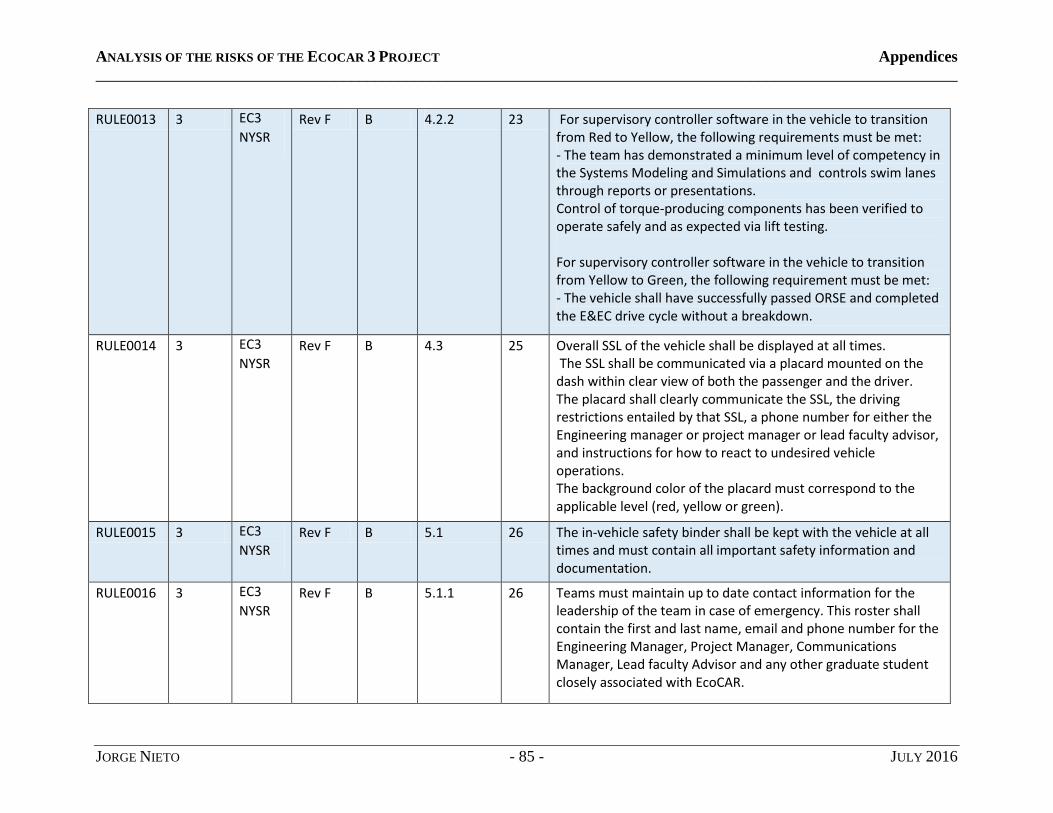
ANALYSIS OF THE RISKS OF THE ECOCAR 3 PROJECT Appendices
____________________________________________________________________________________________________________
JORGE NIETO - 85 - JULY 2016
RULE0013 3 EC3
NYSR Rev F B 4.2.2 23 For supervisory controller software in the vehicle to transition
from Red to Yellow, the following requirements must be met: - The team has demonstrated a minimum level of competency in the Systems Modeling and Simulations and controls swim lanes through reports or presentations. Control of torque-producing components has been verified to operate safely and as expected via lift testing. For supervisory controller software in the vehicle to transition from Yellow to Green, the following requirement must be met: - The vehicle shall have successfully passed ORSE and completed the E&EC drive cycle without a breakdown.
RULE0014 3 EC3
NYSR Rev F B 4.3 25 Overall SSL of the vehicle shall be displayed at all times.
The SSL shall be communicated via a placard mounted on the dash within clear view of both the passenger and the driver. The placard shall clearly communicate the SSL, the driving restrictions entailed by that SSL, a phone number for either the Engineering manager or project manager or lead faculty advisor, and instructions for how to react to undesired vehicle operations. The background color of the placard must correspond to the applicable level (red, yellow or green).
RULE0015 3 EC3
NYSR Rev F B 5.1 26 The in-vehicle safety binder shall be kept with the vehicle at all
times and must contain all important safety information and documentation.
RULE0016 3 EC3
NYSR Rev F B 5.1.1 26 Teams must maintain up to date contact information for the
leadership of the team in case of emergency. This roster shall contain the first and last name, email and phone number for the Engineering Manager, Project Manager, Communications Manager, Lead faculty Advisor and any other graduate student closely associated with EcoCAR.
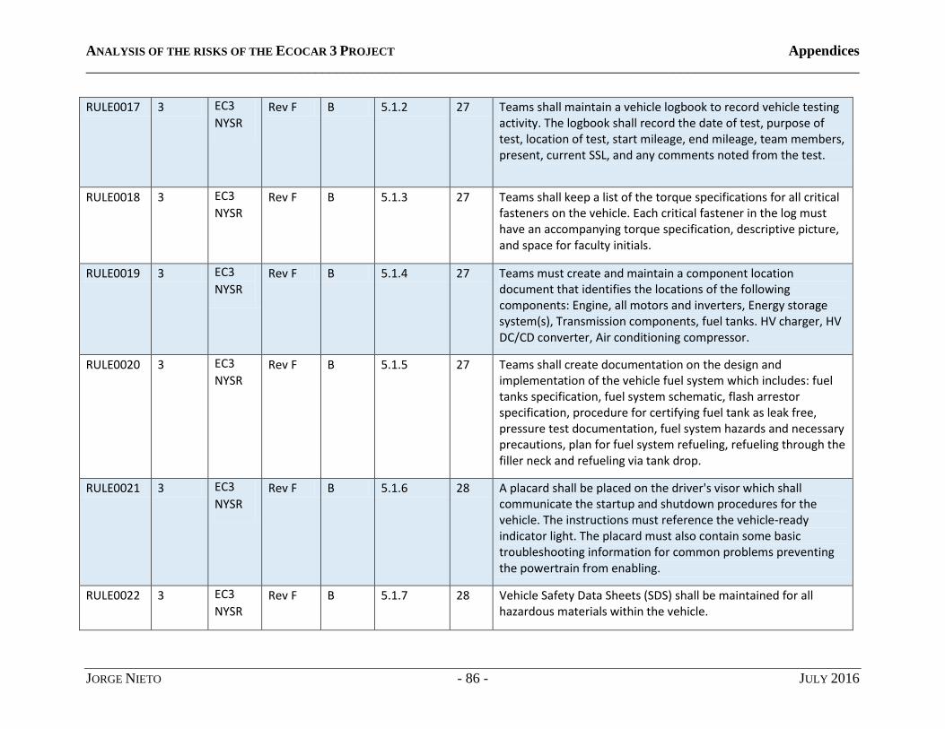
ANALYSIS OF THE RISKS OF THE ECOCAR 3 PROJECT Appendices
____________________________________________________________________________________________________________
JORGE NIETO - 86 - JULY 2016
RULE0017 3 EC3
NYSR Rev F B 5.1.2 27 Teams shall maintain a vehicle logbook to record vehicle testing
activity. The logbook shall record the date of test, purpose of test, location of test, start mileage, end mileage, team members, present, current SSL, and any comments noted from the test.
RULE0018 3 EC3
NYSR Rev F B 5.1.3 27 Teams shall keep a list of the torque specifications for all critical
fasteners on the vehicle. Each critical fastener in the log must have an accompanying torque specification, descriptive picture, and space for faculty initials.
RULE0019 3 EC3
NYSR Rev F B 5.1.4 27 Teams must create and maintain a component location
document that identifies the locations of the following components: Engine, all motors and inverters, Energy storage system(s), Transmission components, fuel tanks. HV charger, HV DC/CD converter, Air conditioning compressor.
RULE0020 3 EC3
NYSR Rev F B 5.1.5 27 Teams shall create documentation on the design and
implementation of the vehicle fuel system which includes: fuel tanks specification, fuel system schematic, flash arrestor specification, procedure for certifying fuel tank as leak free, pressure test documentation, fuel system hazards and necessary precautions, plan for fuel system refueling, refueling through the filler neck and refueling via tank drop.
RULE0021 3 EC3
NYSR Rev F B 5.1.6 28 A placard shall be placed on the driver's visor which shall
communicate the startup and shutdown procedures for the vehicle. The instructions must reference the vehicle-ready indicator light. The placard must also contain some basic troubleshooting information for common problems preventing the powertrain from enabling.
RULE0022 3 EC3
NYSR Rev F B 5.1.7 28 Vehicle Safety Data Sheets (SDS) shall be maintained for all
hazardous materials within the vehicle.

ANALYSIS OF THE RISKS OF THE ECOCAR 3 PROJECT Appendices
____________________________________________________________________________________________________________
JORGE NIETO - 87 - JULY 2016
RULE0023 3 EC3
NYSR Rev F B 5.1.8 28 Teams shall provide copies of any waiver that was approved and
executed on the vehicle.
RULE0024 3 EC3
NYSR Rev F B 5.2 29 The facilities binder containing important safety information and
documentation must be stored in the team's laboratory space in an easily accessible and clearly labeled location. Every document must include the name of the author, the document revision number, and the date of revision. A change log must also be maintained to document changes to all facilities binder contents.
RULE0025 3 EC3
NYSR Rev F B 5.2.1 29 Vehicle Safety Data Sheets (SDS) shall be maintained for all
hazardous materials within the vehicle.
RULE0026 3 EC3
NYSR Rev F B 5.2.2 29 Quick reference guide for electrical safety shall be developed. At
minimum, it must contain guidance on : Fuse sizing for LV and HV systems, Wire ampacity for wires used in EcoCar, High power electrical connections in batteries or components, use of electrical insulation for LV and HV, use of flexible wire conduit/loom, wire routing, and wire labeling, proper terminal crimping and/or soldering practices.
RULE0027 3 EC3
NYSR Rev F B 5.2.3 30 Quick reference guide for mechanical safety shall be developed
containing guidance on the following topics: -appropriate use and selection of mechanical fasteners -appropriate use of fastener locking means -protection for rotating components.

ANALYSIS OF THE RISKS OF THE ECOCAR 3 PROJECT Appendices
____________________________________________________________________________________________________________
JORGE NIETO - 88 - JULY 2016
RULE0028 3 EC3
NYSR Rev F B 5.2.4 30 Teams must obtain or create Standard Operating Procedures
(SOPs) for every piece of garage or laboratory equipment that poses a significant danger or hazard to the operator. At minimum, SOPs must be created for the following: --vehicle lift -machine shop equipment -wielding shop equipment -hand operated power tools -stationary power tools such as bench grinder -motors, engines, batteries, etc., used in a test stand environment Each SOP must include the following information at a minimum: - Specific safety precautions and hazards associated with equipment operation -PPE required for operation -Instructions for safe operation -Emergency shutdown procedures -Instructions for changing parts or adjusting settings.
RULE0029 3 EC3
NYSR Rev F B 5.2.5 30 Teams shall maintain SDSs for all hazardous materials stored or
used in their facilities.
RULE0030 3 EC3
NYSR Rev F D 4.1 38 Fuel activity of any type (including oil) will not be permitted. The
approved fuel that can be used in EcoCar 3 are E10 (10% ethanol, 90% gasoline), E85 (85% ethanol, 15% gasoline), and B20 (20% biodiesel, 80% petro-diesel).Grid electricity is also an approved energy source.
RULE0031 3 EC3
NYSR Rev F D 4.2 38 The manual transmission if used cannot be driver controlled. It
must be actuated by the vehicle control strategy (i.e., an automated manual transmission). Teams may not sue engine from the production vehicle as the engine in their powertrain architecture.
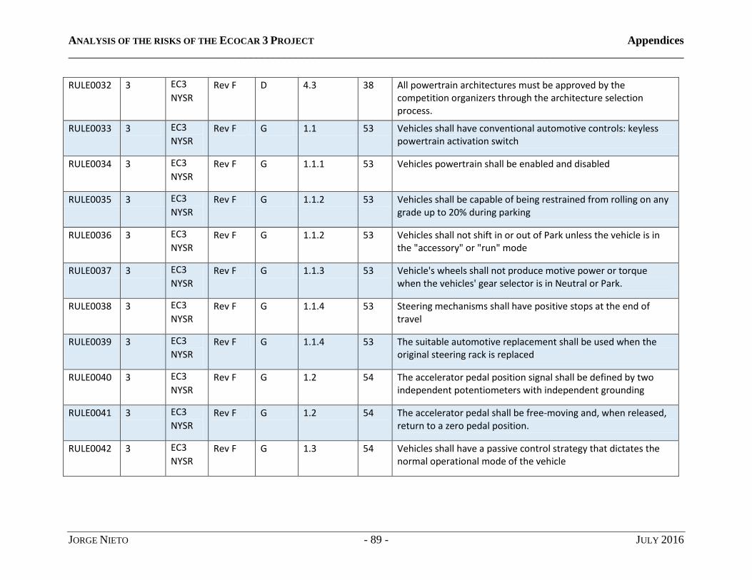
ANALYSIS OF THE RISKS OF THE ECOCAR 3 PROJECT Appendices
____________________________________________________________________________________________________________
JORGE NIETO - 89 - JULY 2016
RULE0032 3 EC3
NYSR Rev F D 4.3 38 All powertrain architectures must be approved by the
competition organizers through the architecture selection process.
RULE0033 3 EC3
NYSR Rev F G 1.1 53 Vehicles shall have conventional automotive controls: keyless
powertrain activation switch
RULE0034 3 EC3
NYSR Rev F G 1.1.1 53 Vehicles powertrain shall be enabled and disabled
RULE0035 3 EC3
NYSR Rev F G 1.1.2 53 Vehicles shall be capable of being restrained from rolling on any
grade up to 20% during parking
RULE0036 3 EC3
NYSR Rev F G 1.1.2 53 Vehicles shall not shift in or out of Park unless the vehicle is in
the "accessory" or "run" mode
RULE0037 3 EC3
NYSR Rev F G 1.1.3 53 Vehicle's wheels shall not produce motive power or torque
when the vehicles' gear selector is in Neutral or Park.
RULE0038 3 EC3
NYSR Rev F G 1.1.4 53 Steering mechanisms shall have positive stops at the end of
travel
RULE0039 3 EC3
NYSR Rev F G 1.1.4 53 The suitable automotive replacement shall be used when the
original steering rack is replaced
RULE0040 3 EC3
NYSR Rev F G 1.2 54 The accelerator pedal position signal shall be defined by two
independent potentiometers with independent grounding
RULE0041 3 EC3
NYSR Rev F G 1.2 54 The accelerator pedal shall be free-moving and, when released,
return to a zero pedal position.
RULE0042 3 EC3
NYSR Rev F G 1.3 54 Vehicles shall have a passive control strategy that dictates the
normal operational mode of the vehicle
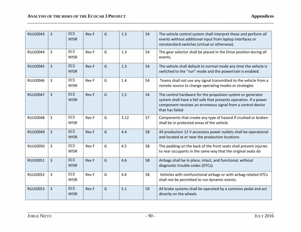
ANALYSIS OF THE RISKS OF THE ECOCAR 3 PROJECT Appendices
____________________________________________________________________________________________________________
JORGE NIETO - 90 - JULY 2016
RULE0043 3 EC3
NYSR Rev F G 1.3 54 The vehicle control system shall interpret these and perform all
events without additional input from laptop interfaces or nonstandard switches (virtual or otherwise).
RULE0044 3 EC3
NYSR Rev F G 1.3 54 The gear selector shall be placed in the Drive position during all
events.
RULE0045 3 EC3
NYSR Rev F G 1.3 54 The vehicle shall default to normal mode any time the vehicle is
switched to the “run” mode and the powertrain is enabled.
RULE0046 3 EC3
NYSR Rev F G 1.4 54 Teams shall not use any signal transmitted to the vehicle from a
remote source to change operating modes or strategies
RULE0047 3 EC3
NYSR Rev F G 1.5 54 The control hardware for the propulsion system or generator
system shall have a fail-safe that prevents operation. If a power component receives an erroneous signal from a control device that has failed
RULE0048 3 EC3
NYSR Rev F G 3.12 57 Components that create any type of hazard if crushed or broken
shall be in protected areas of the vehicle
RULE0049 3 EC3
NYSR Rev F G 4.4 58 All production 12 V accessory power outlets shall be operational
and located at or near the production locations
RULE0050 3 EC3
NYSR Rev F G 4.5 58 The padding on the back of the front seats shall prevent injuries
to rear occupants in the same way that the original seats do
RULE0051 3 EC3
NYSR Rev F G 4.6 58 Airbags shall be in place, intact, and functional, without
diagnostic trouble codes (DTCs).
RULE0052 3 EC3
NYSR Rev F G 4.6 58 Vehicles with nonfunctional airbags or with airbag-related DTCs
shall not be permitted to run dynamic events.
RULE0053 3 EC3
NYSR Rev F G 5.1 59 All brake systems shall be operated by a common pedal and act
directly on the wheels
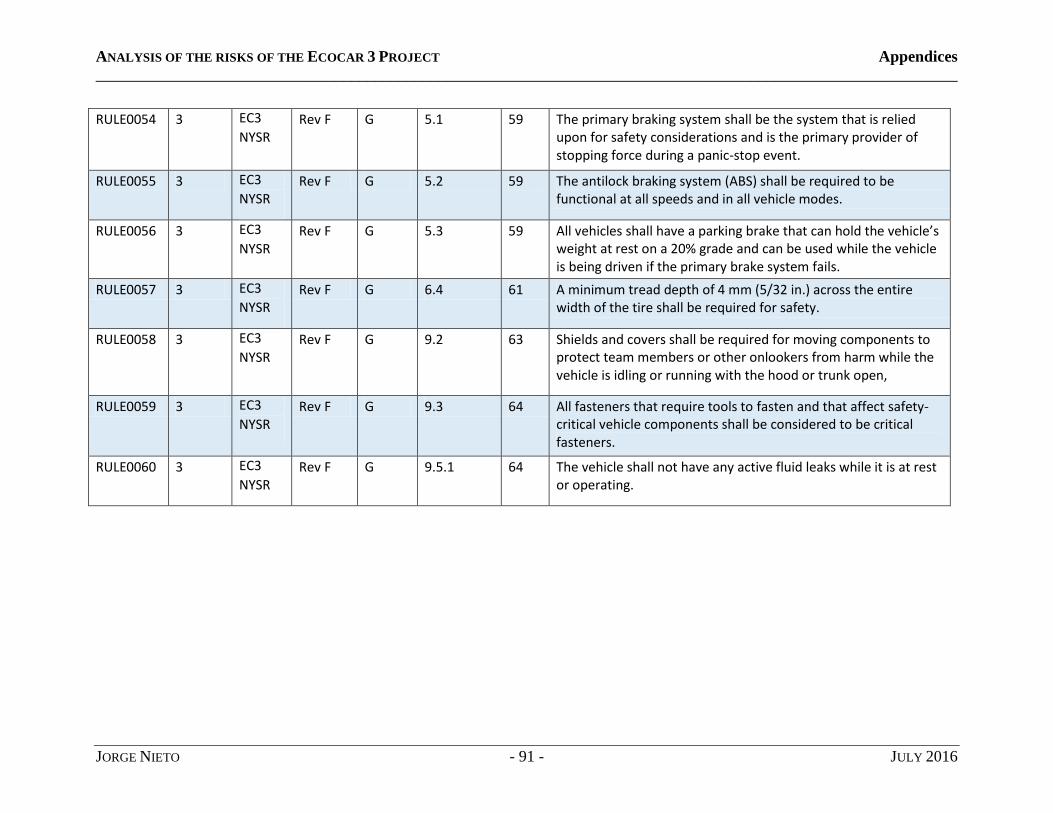
ANALYSIS OF THE RISKS OF THE ECOCAR 3 PROJECT Appendices
____________________________________________________________________________________________________________
JORGE NIETO - 91 - JULY 2016
RULE0054 3 EC3
NYSR Rev F G 5.1 59 The primary braking system shall be the system that is relied
upon for safety considerations and is the primary provider of stopping force during a panic-stop event.
RULE0055 3 EC3
NYSR Rev F G 5.2 59 The antilock braking system (ABS) shall be required to be
functional at all speeds and in all vehicle modes.
RULE0056 3 EC3
NYSR Rev F G 5.3 59 All vehicles shall have a parking brake that can hold the vehicle’s
weight at rest on a 20% grade and can be used while the vehicle is being driven if the primary brake system fails.
RULE0057 3 EC3
NYSR Rev F G 6.4 61 A minimum tread depth of 4 mm (5/32 in.) across the entire
width of the tire shall be required for safety.
RULE0058 3 EC3
NYSR Rev F G 9.2 63 Shields and covers shall be required for moving components to
protect team members or other onlookers from harm while the vehicle is idling or running with the hood or trunk open,
RULE0059 3 EC3
NYSR Rev F G 9.3 64 All fasteners that require tools to fasten and that affect safety-
critical vehicle components shall be considered to be critical fasteners.
RULE0060 3 EC3
NYSR Rev F G 9.5.1 64 The vehicle shall not have any active fluid leaks while it is at rest
or operating.

ANALYSIS OF THE RISKS OF THE ECOCAR 3 PROJECT Appendices
____________________________________________________________________________________________________________
JORGE NIETO - 92 - JULY 2016
RULE0061 3 EC3
NYSR Rev F H 3 67 Any modification to the vehicle that could impact vehicle safety
requires a waiver/ Modifications to the following systems will generally be allowed with a waiver: - Modifications to the front or rear sub frame -Modifications to yellow zones identified in the vehicle body modification guide - Modifying any body structure within 200 mm of a sear or seatbelt mount. -Mounting components within 100 mm of an SDM. -Modifications to vehicle hood or trunk. - Addition of semi-active or active dampers. -Powertrain designs using a boost converter to exceed the maximum voltage limit. -Wires routed outside the frame rails. - Changes to front or rear brake pads, rotors or calipers. The following designs or modifications do not require a waiver for teams to execute, but have other design requirements: -Modifications to vehicle springs, sway bars and dampers -Skid plates -Fuel tanks -Powertrain mounts -ESS mounting structure.
RULE0062 3 EC3
NYSR Rev F I 1.2 81 All components used shall have appropriate ratings for the
environments in which they are used. The ratings include those for temperature, waterproofing, chemical compatibility, etc.
RULE0063 3 EC3
NYSR Rev F I 1.2 81 All small electrical connections and parts (terminal strips,
junctions, shunts, relays, etc.) shall be contained in an enclosed box whenever practical.
RULE0064 3 EC3
NYSR Rev F I 1.2 81 All electrical connections shall be rated for the environments in
which they operate.

ANALYSIS OF THE RISKS OF THE ECOCAR 3 PROJECT Appendices
____________________________________________________________________________________________________________
JORGE NIETO - 93 - JULY 2016
RULE0065 3 EC3
NYSR Rev F I 1.2 82 The environments in which the components are placed shall be
compatible with the component ratings.
RULE0066 3 EC3
NYSR Rev F I 1.3 82 All wiring inside the vehicle shall not be run in paths where it
may get crushed or otherwise damaged.
RULE0067 3 EC3
NYSR Rev F I 1.3 82 All wiring on the exterior of the vehicle shall be run through split
loom or an equivalent protective conduit.
RULE0068 3 EC3
NYSR Rev F I 1.3 82 All wiring shall be protected from chafing on sharp edges or
where it passes through a panel.
RULE0069 3 EC3
NYSR Rev F I 1.3 82 All wiring shall be strain-relieved and securely fastened
throughout the vehicle to minimize movement.
RULE0070 3 EC3
NYSR Rev F I 1.3 82 Wires shall be secured to prevent them from getting caught in
rotating parts, falling on hot surfaces, or snagging on road features.
RULE0071 3 EC3
NYSR Rev F I 1.4 82 All electrical connections shall be made with appropriate
terminals.
RULE0072 3 EC3
NYSR Rev F I 1.5 82 All components and wiring shall be appropriately protected from
overcurrent situations.
RULE0073 3 EC3
NYSR Rev F I 1.6 82 All parallel circuits shall be individually protected by an
overcurrent protection device.
RULE0074 3 EC3
NYSR Rev F I 1.7 82 The PV and LV cells shall be protected from damage (e.g., rain,
physical contact) and must be completely covered to prevent electrical contact.
RULE0075 3 EC3
NYSR Rev F I 1.7 82 Solar panels used to charge/augment the 12 V system shall be
disconnected from the system when the ignition key is in the Off position.
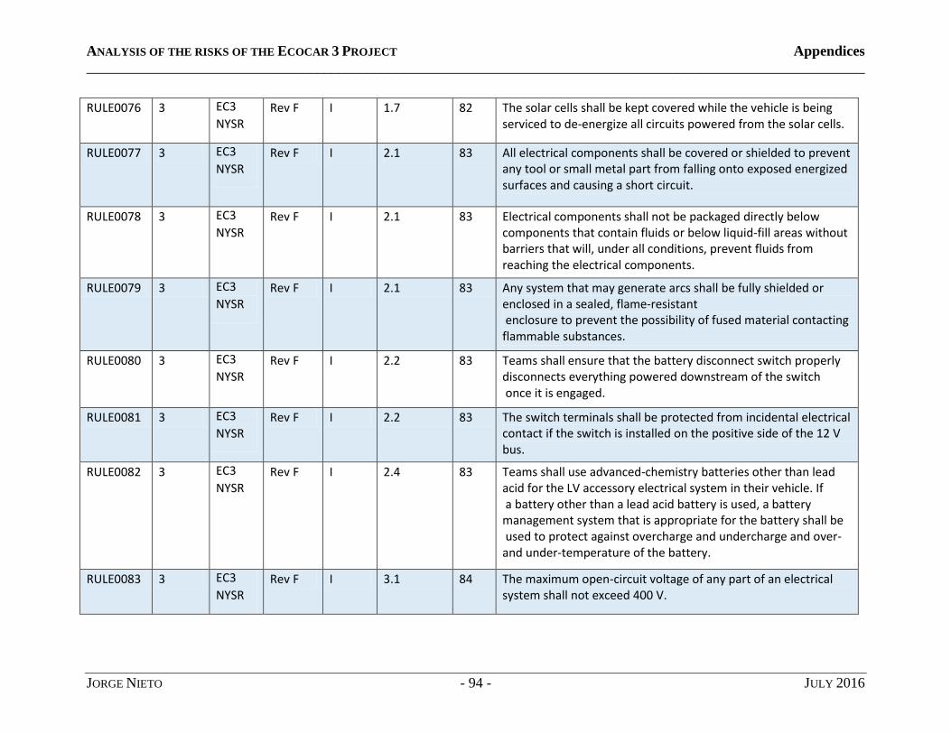
ANALYSIS OF THE RISKS OF THE ECOCAR 3 PROJECT Appendices
____________________________________________________________________________________________________________
JORGE NIETO - 94 - JULY 2016
RULE0076 3 EC3
NYSR Rev F I 1.7 82 The solar cells shall be kept covered while the vehicle is being
serviced to de-energize all circuits powered from the solar cells.
RULE0077 3 EC3
NYSR Rev F I 2.1 83 All electrical components shall be covered or shielded to prevent
any tool or small metal part from falling onto exposed energized surfaces and causing a short circuit.
RULE0078 3 EC3
NYSR Rev F I 2.1 83 Electrical components shall not be packaged directly below
components that contain fluids or below liquid-fill areas without barriers that will, under all conditions, prevent fluids from reaching the electrical components.
RULE0079 3 EC3
NYSR Rev F I 2.1 83 Any system that may generate arcs shall be fully shielded or
enclosed in a sealed, flame-resistant enclosure to prevent the possibility of fused material contacting flammable substances.
RULE0080 3 EC3
NYSR Rev F I 2.2 83 Teams shall ensure that the battery disconnect switch properly
disconnects everything powered downstream of the switch once it is engaged.
RULE0081 3 EC3
NYSR Rev F I 2.2 83 The switch terminals shall be protected from incidental electrical
contact if the switch is installed on the positive side of the 12 V bus.
RULE0082 3 EC3
NYSR Rev F I 2.4 83 Teams shall use advanced-chemistry batteries other than lead
acid for the LV accessory electrical system in their vehicle. If a battery other than a lead acid battery is used, a battery management system that is appropriate for the battery shall be used to protect against overcharge and undercharge and over- and under-temperature of the battery.
RULE0083 3 EC3
NYSR Rev F I 3.1 84 The maximum open-circuit voltage of any part of an electrical
system shall not exceed 400 V.

ANALYSIS OF THE RISKS OF THE ECOCAR 3 PROJECT Appendices
____________________________________________________________________________________________________________
JORGE NIETO - 95 - JULY 2016
RULE0084 3 EC3
NYSR Rev F I 3.2 84 No HV components or wiring shall be located within the
passenger compartment or in the low-speed crush zones designated
RULE0085 3 EC3
NYSR Rev F I 3.3 84 Any enclosures containing HV shall be properly labeled,
“Warning High Voltage.”
RULE0086 3 EC3
NYSR Rev F I 3.3 84 All components containing HV that is not de-energized by the
EDS shall be labeled with “Warning High Voltage Always Energized.”
RULE0087 3 EC3
NYSR Rev F I 3.4 84 All HV wiring in the vehicle shall be covered by a protective
loom.
RULE0088 3 EC3
NYSR Rev F I 3.4 84 HV lines shall avoid jack points and must not be the lowest point
of the vehicle.
RULE0089 3 EC3
NYSR Rev F I 3.6 85 There shall be no exposed HV on the vehicle.
RULE0090 3 EC3
NYSR Rev F I 3.6 85 All HV systems shall remain covered when non-HV systems are
being serviced.
RULE0091 3 EC3
NYSR Rev F I 3.6 85 Every effort shall be made to prevent exposed HV connections,
which could result in fire or hazardous electrical accidents.
RULE0092 3 EC3
NYSR Rev F I 3.6 85 All shielded connectors shall follow proper grounding practices
and shall be checked for loss of isolation through the shielding.
RULE0093 3 EC3
NYSR Rev F I 3.6 85 All HV connectors and enclosures shall be finger-proof.
RULE0094 3 EC3
NYSR Rev F I 3.7 86 The included sealing cap shall be fastened near the receptacle
with the attached chain and must be used to keep the receptacle from being exposed when not in use.

ANALYSIS OF THE RISKS OF THE ECOCAR 3 PROJECT Appendices
____________________________________________________________________________________________________________
JORGE NIETO - 96 - JULY 2016
RULE0095 3 EC3
NYSR Rev F I 3.1 87 If both high and low voltages are present in an enclosure,
they shall be separated by an insulating barrier with adequate dielectric strength, or must maintain the following spacing through the air:
RULE0096 3 EC3
NYSR Rev F I 3.11 88 All HV circuits shall be in an enclosure rated for use with HV
components.
RULE0097 3 EC3
NYSR Rev F I 3.11 88 HV enclosures shall be clearly labeled “Danger High Voltage” and
contain access panels that can be removed only through the use of tools.
RULE0098 3 EC3
NYSR Rev F I 3.12 88 All insulating barriers and coatings shall be tough enough to
prevent HV parts from cutting through in the event of hard contact.
RULE0099 3 EC3
NYSR Rev F I 3.13.1 88 Teams that design a PHEV or EREV shall have a HV charger that is
securely mounted on-board the vehicle.
RULE0100 3 EC3
NYSR Rev F I 3.13.3 89 Plugs shall be located outside the vehicle and have a watertight
sealing cover to prevent incidental contact and moisture intrusion.
RULE0101 3 EC3
NYSR Rev F I 3.14 89 Capacitors shall not develop pressures capable of causing injury
to persons should the capacitor malfunction.
RULE0102 3 EC3
NYSR Rev F I 3.14 89 A capacitor containing flammable materials shall not pose the
risk of a fire or electric shock under any conditions, including internal shorting.
RULE0103 3 EC3
NYSR Rev F I 3.14 89 The capacitor shall be constructed to reduce the risk of expelling
hazardous materials, and it must be housed properly.
RULE0104 3 EC3
NYSR Rev F I 4.1 89 The structure of the battery pack shall be securely fastened to
the vehicle frame at as many points as is practical to distribute the load.
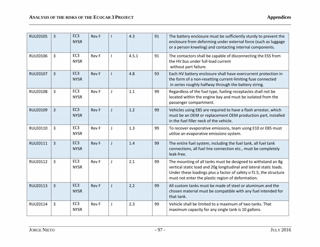
ANALYSIS OF THE RISKS OF THE ECOCAR 3 PROJECT Appendices
____________________________________________________________________________________________________________
JORGE NIETO - 97 - JULY 2016
RULE0105 3 EC3
NYSR Rev F I 4.3 91 The battery enclosure must be sufficiently sturdy to prevent the
enclosure from deforming under external force (such as luggage or a person kneeling) and contacting internal components.
RULE0106 3 EC3
NYSR Rev F I 4.5.1 91 The contactors shall be capable of disconnecting the ESS from
the HV bus under full-load current without part failure.
RULE0107 3 EC3
NYSR Rev F I 4.8 93 Each HV battery enclosure shall have overcurrent protection in
the form of a non-resetting current-limiting fuse connected in series roughly halfway through the battery string.
RULE0108 3 EC3
NYSR Rev F J 1.1 99 Regardless of the fuel type, fueling receptacles shall not be
located within the engine bay and must be isolated from the passenger compartment.
RULE0109 3 EC3
NYSR Rev F J 1.2 99 Vehicles using E85 are required to have a flash arrestor, which
must be an OEM or replacement OEM production part, installed in the fuel filler neck of the vehicle.
RULE0110 3 EC3
NYSR Rev F J 1.3 99 To recover evaporative emissions, team using E10 or E85 must
utilize an evaporative emissions system.
RULE0111 3 EC3
NYSR Rev F J 1.4 99 The entire fuel system, including the fuel tank, all fuel tank
connections, all fuel line connection etc., must be completely leak-free.
RULE0112 3 EC3
NYSR Rev F J 2.1 99 The mounting of all tanks must be designed to withstand an 8g
vertical static load and 20g longitudinal and lateral static loads. Under these loadings plus a factor of safety o f1.5, the structure must not enter the plastic region of deformation.
RULE0113 3 EC3
NYSR Rev F J 2.2 99 All custom tanks must be made of steel or aluminum and the
chosen material must be compatible with any fuel intended for that tank.
RULE0114 3 EC3
NYSR Rev F J 2.3 99 Vehicle shall be limited to a maximum of two tanks. That
maximum capacity for any single tank is 10 gallons.

ANALYSIS OF THE RISKS OF THE ECOCAR 3 PROJECT Appendices
____________________________________________________________________________________________________________
JORGE NIETO - 98 - JULY 2016
RULE0115 3 EC3
NYSR Rev F J 2.4 100 No fuel system component may be located outside the frame
rail, behind the rear axle or forward of the front axle.
RULE0116 3 EC3
NYSR Rev F J 2.5 100 To ensure leak-proof operation and overall robustness, fuel
tanks must be pressure tested at 9 psig. Liquid fuel tanks must have a gaseous pressure release valve set to less than 3 psig.
RULE0117 3 EC3
NYSR Rev F J 2.6.1 100 All liquid fuel tanks must be designed for installation or removal
within 15 minutes, beginning after the vehicle has raised on a hoist. A 25-mm clearance must be maintained around adjacent solid structures to aid in ease of installation. The removal of the tank shall not require the removal of the exhaust or other major vehicle components. The installation or removal of the tank shall not require the simultaneous connections of fuel lines and placement/removal of the tank in the vehicle.
RULE0118 3 EC3
NYSR Rev F J 2.6.2 100 All tank connections must have the capability to be sealed.
These seals must prevent leaks from any tank port or connect when the tank is inverted. Temporary corks or plugs are prohibited; all sealing mechanisms must be secure. All fuel-line-to -tank connections shall use double-disconnect-type-connectors that minimize fuel spillage. Use of barbed fittings or hose clamp connections is not permitted for fittings associated with tank removal. This rule does not apply to the filler neck to tank connection. Additionally, Filler-neck-to-tank connections must have capability to be sealed when the tank is removed from the vehicle. All flexible fuel lines left attached to the tank must be less than 12 in. long.

ANALYSIS OF THE RISKS OF THE ECOCAR 3 PROJECT Appendices
____________________________________________________________________________________________________________
JORGE NIETO - 99 - JULY 2016
RULE0119 3 EC3
NYSR Rev F J 2.6.3 101 All tanks shall have a unique connection to fill the fuel tank from
the fuel receptacle using a conventional filler neck. This port must not be prone to spills during the tank removal and filling process. Additionally, this port must have the capability to be securely sealed.
RULE0120 3 EC3
NYSR Rev F J 2.6.4 101 All tanks shall have a circular, sealable fueling port between 1.5
in. and 2 in. in diameter that is located such that the maximum fueling fluid capacity of the tank can be achieved while the tank is lying on a flat surface outside the vehicle.
RULE0121 3 EC3
NYSR Rev F J 2.6.5 101 Fuel tanks must have a venting bung at the top of the tank. The
bung must measure between 3/4 in. and 1 in. diameter, and it must be able to be fully sealed when not in use.
RULE0122 3 EC3
NYSR Rev F J 2.6.6 101 A grounding point is required on all tanks. The grounding point
must be a stud or plate between 1/4 in, and 3/8 in. in diameter or maximum plate thickness, and it must have 2in. of clearance for the clamp surrounding the lug.
RULE0123 3 EC3
NYSR Rev F J 2.8 101 Teams that employ tank straps must provide a wear resistant
barrier (i.e., rubber or plastic) between the metal tank and the strap.
RULE0124 3 EC3
NYSR Rev F K 1 102 Vehicles shall have an EDS to shut down the HV and fuel
systems.
RULE0125 3 EC3
NYSR Rev F K 1 102 Activation of any of the EDS switches shall not disable or inhibit
power steering or the primary braking system and shall not create a greater hazard to vehicle occupants or bystanders.
RULE0126 3 EC3
NYSR Rev F K 1.2 104 Inertias switch shall operate in the event of a vehicle crash
exceeding 8g of acceleration
RULE0127 3 EC3
NYSR Rev F K 2 104 All vehicles shall have a 5-lb. (minimum) Class ABC fire
extinguisher on-board.
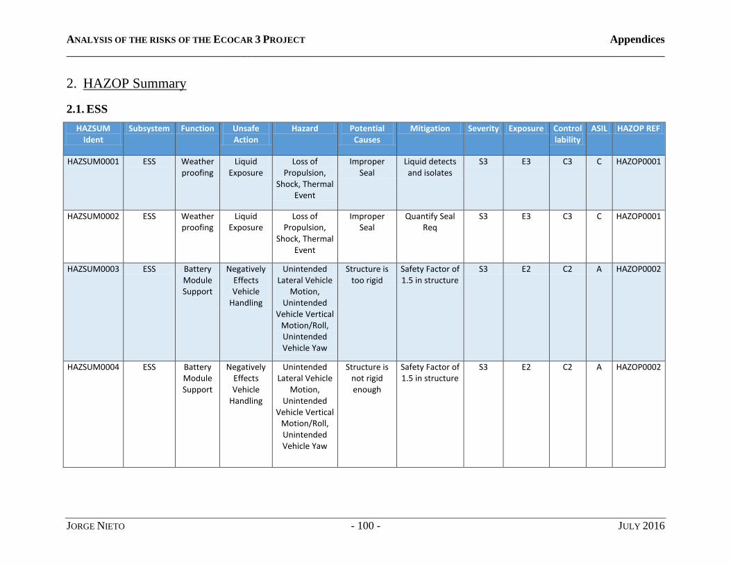
ANALYSIS OF THE RISKS OF THE ECOCAR 3 PROJECT Appendices
____________________________________________________________________________________________________________
JORGE NIETO - 100 - JULY 2016
2. HAZOP Summary
2.1. ESS
HAZSUM Ident
Subsystem Function Unsafe Action
Hazard Potential Causes
Mitigation Severity Exposure Controllability
ASIL HAZOP REF
HAZSUM0001 ESS Weather proofing
Liquid Exposure
Loss of Propulsion,
Shock, Thermal Event
Improper Seal
Liquid detects and isolates
S3 E3 C3 C HAZOP0001
HAZSUM0002 ESS Weather proofing
Liquid Exposure
Loss of Propulsion,
Shock, Thermal Event
Improper Seal
Quantify Seal Req
S3 E3 C3 C HAZOP0001
HAZSUM0003 ESS Battery Module Support
Negatively Effects Vehicle
Handling
Unintended Lateral Vehicle
Motion, Unintended
Vehicle Vertical Motion/Roll, Unintended Vehicle Yaw
Structure is too rigid
Safety Factor of 1.5 in structure
S3 E2 C2 A HAZOP0002
HAZSUM0004 ESS Battery Module Support
Negatively Effects Vehicle
Handling
Unintended Lateral Vehicle
Motion, Unintended
Vehicle Vertical Motion/Roll, Unintended Vehicle Yaw
Structure is not rigid enough
Safety Factor of 1.5 in structure
S3 E2 C2 A HAZOP0002

ANALYSIS OF THE RISKS OF THE ECOCAR 3 PROJECT Appendices
____________________________________________________________________________________________________________
JORGE NIETO - 101 - JULY 2016
HAZSUM0005 ESS Control Module Support
Control Module Support Failure
Loss of Propulsion
Mounting is not sufficient
to loading and shock
The mounting of all tanks
must be designed to
withstand an 8g vertical static load and 20g longitudinal and lateral
static loads. Under these
loadings plus a factor of safety
of 1.5, the structure must not enter the
plastic region of deformation.
S2 E2 C3 A HAZOP0003
HAZSUM0006 ESS User Safety
HV Exposure
Shock, Thermal Injury, Thermal
Event
HV Component
Exposure
Guidelines shall be provided to disable and to re-enable the vehicle for HV vehicle system
service
S3 E2 C2 A HAZOP0004 HAZOP0006 HAZOP0007 HAZOP0008
HAZSUM0007 ESS User Safety
HV Exposure
Shock, Thermal Injury, Thermal
Event
HV Component
Exposure
Procedures to safetly access
and service the ESS or other
live HV in vehilce must be
provided
S3 E2 C2 A HAZOP0004 HAZOP0006 HAZOP0007 HAZOP0008
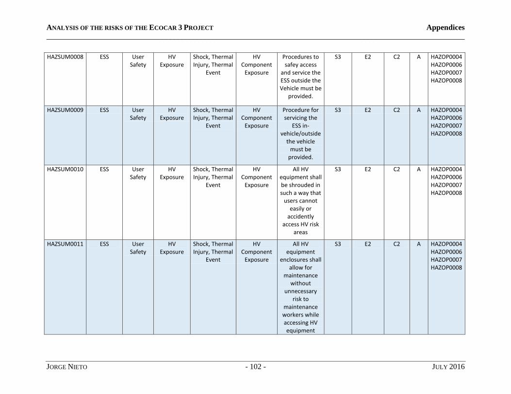
ANALYSIS OF THE RISKS OF THE ECOCAR 3 PROJECT Appendices
____________________________________________________________________________________________________________
JORGE NIETO - 102 - JULY 2016
HAZSUM0008 ESS User Safety
HV Exposure
Shock, Thermal Injury, Thermal
Event
HV Component
Exposure
Procedures to safey access
and service the ESS outside the Vehicle must be
provided.
S3 E2 C2 A HAZOP0004 HAZOP0006 HAZOP0007 HAZOP0008
HAZSUM0009 ESS User Safety
HV Exposure
Shock, Thermal Injury, Thermal
Event
HV Component
Exposure
Procedure for servicing the
ESS in-vehicle/outside
the vehicle must be
provided.
S3 E2 C2 A HAZOP0004 HAZOP0006 HAZOP0007 HAZOP0008
HAZSUM0010 ESS User Safety
HV Exposure
Shock, Thermal Injury, Thermal
Event
HV Component
Exposure
All HV equipment shall be shrouded in such a way that
users cannot easily or
accidently access HV risk
areas
S3 E2 C2 A HAZOP0004 HAZOP0006 HAZOP0007 HAZOP0008
HAZSUM0011 ESS User Safety
HV Exposure
Shock, Thermal Injury, Thermal
Event
HV Component
Exposure
All HV equipment
enclosures shall allow for
maintenance without
unnecessary risk to
maintenance workers while accessing HV equipment
S3 E2 C2 A HAZOP0004 HAZOP0006 HAZOP0007 HAZOP0008

ANALYSIS OF THE RISKS OF THE ECOCAR 3 PROJECT Appendices
____________________________________________________________________________________________________________
JORGE NIETO - 103 - JULY 2016
HAZSUM0012 ESS Luggage Support
HV Exposure
Loss of Propulsion,
Shock, Thermal Event
ESS Housing unable to
support the weight of
equipment and luggage by the user
Warning labels with allowable loads visible to
the user
S3 E3 C2 B HAZOP0005
HAZSUM0013 ESS Luggage Support
HV Exposure
Loss of Propulsion,
Shock, Thermal Event
ESS Housing unable to
support the weight of
equipment and luggage by the user
ESS cover shall withstand
130kg in axial loading
S3 E3 C2 B HAZOP0005
HAZSUM0014 ESS Luggage Support
Weather Exposure
Loss of Propulsion,
Shock, Thermal Event
ESS Housing seal fails
under loading
ESS cover shall remained seals with 130kg in axial loading
S3 E3 C2 B HAZOP0005
HAZSUM0015 ESS Cabin Isolation
Occupant fume
exposure
Operator Hazmat
Exposure
Improper external seal
to trunk
ESS housing seals trunk
from external fumes and
liquids
S3 E2 C2 A HAZOP0008
HAZSUM0016 ESS Battery module
temperature mgmt
Battery modeule overheat
Loss of Propulsion,
Shock, Thermal Event
prolong current draw
from modules
active cooling to keep
temperatures nominal
S3 E2 C2 A HAZOP0009
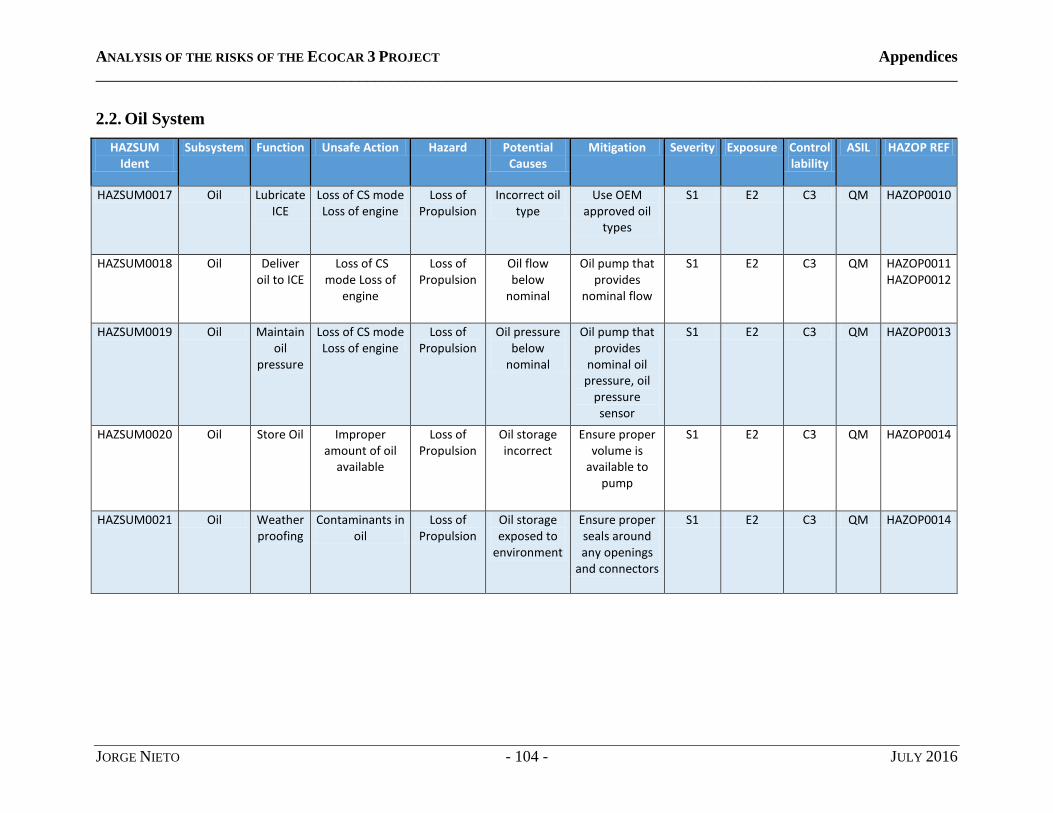
ANALYSIS OF THE RISKS OF THE ECOCAR 3 PROJECT Appendices
____________________________________________________________________________________________________________
JORGE NIETO - 104 - JULY 2016
2.2. Oil System
HAZSUM Ident
Subsystem Function Unsafe Action Hazard Potential Causes
Mitigation Severity Exposure Controllability
ASIL HAZOP REF
HAZSUM0017 Oil Lubricate ICE
Loss of CS mode Loss of engine
Loss of Propulsion
Incorrect oil type
Use OEM approved oil
types
S1 E2 C3 QM HAZOP0010
HAZSUM0018 Oil Deliver oil to ICE
Loss of CS mode Loss of
engine
Loss of Propulsion
Oil flow below
nominal
Oil pump that provides
nominal flow
S1 E2 C3 QM HAZOP0011 HAZOP0012
HAZSUM0019 Oil Maintain oil
pressure
Loss of CS mode Loss of engine
Loss of Propulsion
Oil pressure below
nominal
Oil pump that provides
nominal oil pressure, oil
pressure sensor
S1 E2 C3 QM HAZOP0013
HAZSUM0020 Oil Store Oil Improper amount of oil
available
Loss of Propulsion
Oil storage incorrect
Ensure proper volume is
available to pump
S1 E2 C3 QM HAZOP0014
HAZSUM0021 Oil Weatherproofing
Contaminants in oil
Loss of Propulsion
Oil storage exposed to
environment
Ensure proper seals around any openings
and connectors
S1 E2 C3 QM HAZOP0014

ANALYSIS OF THE RISKS OF THE ECOCAR 3 PROJECT Appendices
____________________________________________________________________________________________________________
JORGE NIETO - 105 - JULY 2016
2.3. Fuel system
HAZSUM Ident
Subsystem Function Unsafe Action
Hazard Potential Causes
Mitigation Severity Exposure Controllability
ASIL HAZOP REF
HAZSUM0022 Fuel Deliver fuel no ICE operation
Loss of Propulsion,
Loss/Reduced Longitudinal
Vehicle Acceleration
improper fuel delivery
Ecotec OEM Fuel pump integrated
with custom fuel tank
S1 E2 C3 QM HAZOP0015 HAZOP0021
HAZSUM0023 Fuel Properly store fuel
air mixed in with fuel
Loss of Propulsion,
Loss/Reduced Longitudinal
Vehicle Acceleration
fuel sloshes in tank
baffles in fuel tank
S1 E2 C3 QM HAZOP0016 HAZOP0021
HAZSUM0024 Fuel Refill fuel level
fuel spillage during refill
Operator Hazmat
Exposure, Environment
Hazmat Exposure
improper sizing or
implementation of filler
with fuel tank
Utilize OEM filler neck
with custom fuel tank, warning
labels
S1 E3 C2 QM HAZOP0017 HAZOP0021
HAZSUM0025 Fuel Condense fuel evap
increased fuel fume exposure
from vehicle
lack of evap system
Ecotec OEM fuel evap system
integrated with custom
fuel tank
HAZOP0018 HAZOP0021
HAZSUM0026 Fuel Maintain fuel
pressure
no/reduced ICE
operation
Loss of Propulsion,
Loss/Reduced Longitudinal
Vehicle Acceleration
improper fuel pressure
Ecotec OEM Fuel pump integrated
with custom fuel tank
S1 E2 C3 QM HAZOP0019 HAZOP0021

ANALYSIS OF THE RISKS OF THE ECOCAR 3 PROJECT Appendices
____________________________________________________________________________________________________________
JORGE NIETO - 106 - JULY 2016
HAZSUM0027 Fuel Monitor fuel level
unknown fuel level to
driver
lack of or improper fuel level sensor
implementation
Utilize Ecotec OEM fuel
level sensor
HAZOP0020
HAZSUM0028 Fuel Fire Prevention
Fuel ignition Thermal Event improper seal,
improper resistance to environment
ensure proper seals around any
openings and connectors,
flash arrestor implemented
S3 E3 C2 B HAZOP0022
HAZSUM0029 Fuel Weatherproofing
fuel contaminati
on
Loss of Propulsion,
Loss/Reduced Longitudinal
Vehicle Acceleration
environmental exposure within fuel
tank
sensure proper seals around any
openings
S1 E2 C3 QM HAZOP0023
HAZSUM0030 Fuel Puncture resistance
Fuel leak Operator Hazmat
Exposure, Environment
Hazmat Exposure,
Thermal Event
fuel tank puncture from FOD
Puncture resistance to
metric
S3 E2 C2 A HAZOP0024

ANALYSIS OF THE RISKS OF THE ECOCAR 3 PROJECT Appendices
____________________________________________________________________________________________________________
JORGE NIETO - 107 - JULY 2016
HAZSUM0031 Fuel Mounting fuel component separation
from system
Operator Hazmat
Exposure, Environment
Hazmat Exposure, Loss of Propulsion, Loss/Reduced Longitudinal
Vehicle Acceleration,
Thermal Event
improper mounting
The mounting of all tanks
must be designed to
withstand an 8g vertical static load
and 20g longitudinal and lateral
static loads. Under these loadings plus
a factor of safety of 1.5, the structure
must not enter the
plastic region of
deformation.
S3 E2 C2 A HAZOP0025

ANALYSIS OF THE RISKS OF THE ECOCAR 3 PROJECT Appendices
____________________________________________________________________________________________________________
JORGE NIETO - 108 - JULY 2016
2.4. Thermal system
HAZSUM Ident
Subsystem Function Unsafe Action
Hazard Potential Causes
Mitigation Severity Exposure Controllability
ASIL HAZOP REF
HAZSUM0032 Thermal Provide cooling to
IMG motors
IMG overtemp
Loss of Propulsion,
Loss/Reduced Longitudinal
Vehicle Acceleration,
Thermal Injury
heat rejection
not sufficient
Thermal sensors on each motor
S2 E2 C2 QM HAZOP0026
HAZSUM0033 Thermal Provide cooling to
inverters/APM
damage to inverters/APM, loss of all HV systems
heat rejection
not sufficient
Thermal sensors on
each inverter
S2 E2 C2 QM HAZOP0027
HAZSUM0034 Thermal Provide cooling to
ICE
damage to ICE/ no ICE operation
No ICE operation,
radiant heat exposure to
other systems, damage to ICE
risk, no C.S. mode
heat rejection
not sufficient
Thermal sensors on
ICE
S3 E2 C2 A HAZOP0028
HAZSUM0035 Thermal Provide cooling to
transmission
damage to transmission
loss of propulsion no engine operation
thermal event
heat rejection
not sufficient
Thermal sensors on
transmission
S3 E2 C2 A HAZOP0029
HAZSUM0036 Thermal Provide cabin
cooling
adverse conditions
for occupants
adverse conditions for
occupants
cabin cooling
not enough
Sensors, proper
sealing of the cabin
S1 E3 C2 QM HAZOP0030

ANALYSIS OF THE RISKS OF THE ECOCAR 3 PROJECT Appendices
____________________________________________________________________________________________________________
JORGE NIETO - 109 - JULY 2016
HAZSUM0037 Thermal Provide cabin
heating
adverse conditions
for occupants
adverse conditions for
occupants
cabin heating
not enough
Sensors, proper
sealing of the cabin
S1 E3 C2 QM HAZOP0031
HAZSUM0038 Thermal Store coolant
Loss of prop. Damage to
main components
Exposure to impurities,
loss of coolant
coolant storage
incorrect improper
seal
baffles in the coolant tank
S2 E2 C3 A HAZOP0032

ANALYSIS OF THE RISKS OF THE ECOCAR 3 PROJECT Appendices
____________________________________________________________________________________________________________
JORGE NIETO - 110 - JULY 2016
3. DFMEA
Note: the DFMEA analysis has been divided in two different tables with half of the information each so that it can fit in this document.
However, the analysis is presented as one sole table in the database of the team.
DFMEAIDENT System Failure Mode Potential Effects
Hazard Potential Causes Existing Prevention
Existing Detection
Mitigations
DFMEA0001 ESS Unintentional Loss of HVIL
Loss of High Voltage Systems
Loss of Propulsion Electrical Connection Failure
None BMS detect none
DFMEA0002 ESS Loss of CAN Communication
Loss of High Voltage Systems
Loss of Propulsion Electrical Connection Failure
None SCU detect none
DFMEA0003 ESS Interal Communication
Loss of High Voltage Systems
Loss of Propulsion Electrical Connection Failure
None BMS detect protect ESS housing from
damage
DFMEA0004 ESS Excess Tempurature
Reduced Vehicle
Performance
Loss of Propulsion, Thermal Injury, Thermal Event
Coolant System Failure
active thermal management
BMS detect
DFMEA0005 ESS Water Detected Loss of High Voltage Systems
Loss of Propulsion, Shock, Thermal
Event
Coolant Leak/Case Puncture/weather
proofing failure
ESS Housing BMS detect Check ESS seal during
maintenance, test before and
after installation
DFMEA0006 ESS Contactors Welded
Always Energized
High Voltage Bus
Loss of Propulsion, Shock, Thermal
Event
Excessive Current while Opening contactor/EPO
minimize current draw prior to ESS
disable, none for emergency
power off
BMS detect avoid epo events
DFMEA0007 ESS Over Current Battery Damage/Loss
of High Voltage systems
Loss of Propulsion, Shock, Thermal
Event
Current flow over threshhold
EPO, fuses, SCU
intervention
BMS detect Open contacts

ANALYSIS OF THE RISKS OF THE ECOCAR 3 PROJECT Appendices
____________________________________________________________________________________________________________
JORGE NIETO - 111 - JULY 2016
DFMEA0008 ESS Under Voltage Battery Damage/Loss
of High Voltage systems
Loss of Propulsion, Shock, Thermal
Event
Unbalanced Cells/Over discharge
EPO BMS detect ensure proper power
management in controls
DFMEA0009 ESS Ground Fault Reduced Vehicle
Performance
Loss of Propulsion, Shock, Thermal
Event
HV Bus Failure/Bus Isolation
Isolation BMS detect
DFMEA0010 BRUSA Loss of CAN Communication
Loss of Wall Charage Ability
Electrical Connection Failure
none MABXII detect
DFMEA0011 BRUSA Loss of Digital Signals
Loss of Wall Charage Ability
Electrical Connection Failure
none correlation between device activation and
ESS charge state
DFMEA0012 BRUSA Over Tempurature
Reduced Charging
Rate
Thermal Injury Cooling Fan Failure internal component
derating
internal detection
DFMEA0013 BRUSA Loss of Control Pilot Signal
Loss of Wall Charage Ability
Electrical Connection Failure
Error Bit internal detection
documentation for end user
DFMEA0014 BRUSA Loss of MAINS Loss of Wall Charage Ability
Electrical Connection
Failure/ Blown Fuse
Error Bit internal detection
documentation for end user
DFMEA0015 BRUSA MAINS fuse blown
Loss of Wall Charage Ability
Excess Current Error Bit MABXII detect
DFMEA0016 BRUSA HV Fuse Blown Loss of Wall Charage Ability
Excess Current voltage mismatch
between ESS and BRUSA via DC link voltage
MABXII detect
DFMEA0017 HVAC Loss of Digital Signal
Loss of AV Electrical Connection Failure
none none

ANALYSIS OF THE RISKS OF THE ECOCAR 3 PROJECT Appendices
____________________________________________________________________________________________________________
JORGE NIETO - 112 - JULY 2016
DFMEA0018 HVAC Loss of Analog Signal
No power feedback
Electrical Connection Failure
MABXII Detect, turn off HVAC
MABXII detect
DFMEA0019 HVAC Loose/damaged line
loss of R134a Physical damage, standard
component wear, improper
installation
none driver detect Clearly document R134a
fill location
DFMEA0020 HVAC Loose/damaged HV wire
HV short, HV disable, HV Compressor
fail
Loss of Propulsion, Thermal Event,
Shock
Physical damage to HV wire
Multiple layers of insulation,
impact resistant
insulation, HV fuses
BMS detect Inspect during maintenance
cycle
DFMEA0021 ACC_PDL Loss of APP1 Tractive performance
disabled
Loss of Propulsion Electrical Connection Failure
redundancy, error causes
loss of traction
SCU detect none
DFMEA0022 ACC_PDL Loss of APP2 Tractive performance
disabled
Loss of Propulsion Electrical Connection Failure
redundancy, error causes
loss of traction
SCU detect none
DFMEA0023 ACC_PDL Stuck Pedal Full torque request
Unintended Acceleration
Physical obstruction
none none
DFMEA0024 BRK_PDL Loss of Position Sensor
Reduced Regen
performance, Reliance on Mechanical
Brakes
Loss/Reduced Vehicle
Deceleration
Electrical Connection Failure
mechanical brakes still operational
BCM/SCU detect none
DFMEA0025 BRK_PDL Mechanical Linkage Failure
Mechanical Brake system
failure
Loss/Reduced Vehicle
Deceleration
Physical damage none none
DFMEA0026 BRK_PDL Stuck Pedal Full application of braking
system
Driver Startle, Uninteded Vehicle
Deceleration
Physical obstruction
None none none

ANALYSIS OF THE RISKS OF THE ECOCAR 3 PROJECT Appendices
____________________________________________________________________________________________________________
JORGE NIETO - 113 - JULY 2016
DFMEAIDENT Severity Exposure Controllability ASIL Validated Compromised Function
Operation Restrictions
DFMEA0001 S1 E3 C2 QM No No
DFMEA0002 S1 E2 C3 QM No No
DFMEA0003 S1 E2 C3 QM No No
DFMEA0004 S3 E2 C2 A No No
DFMEA0005 S3 E3 C3 C No No
DFMEA0006 S3 E2 C2 A No No
DFMEA0007 S3 E4 C2 C No No
DFMEA0008 S3 E1 C3 A No No
DFMEA0009 S1 E1 C3 QM No No
DFMEA0010 S1 E2 C3 QM No No
DFMEA0011 S1 E2 C3 QM No No
DFMEA0012 S1 E2 C1 QM No No
DFMEA0013 S1 E3 C1 QM No No
DFMEA0014 S1 E3 C1 QM No No
DFMEA0015 S1 E2 C3 QM No No
DFMEA0016 S1 E2 C3 QM No No
DFMEA0017 S1 E2 C3 QM No No
DFMEA0018 S1 E2 C1 QM No No
DFMEA0019 S1 E3 C2 QM No Yes Lines not installed, use
windows
DFMEA0020 S3 E2 C2 A No No
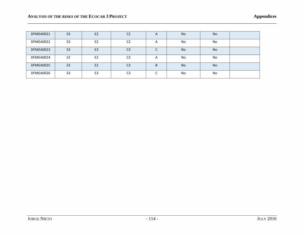
ANALYSIS OF THE RISKS OF THE ECOCAR 3 PROJECT Appendices
____________________________________________________________________________________________________________
JORGE NIETO - 114 - JULY 2016
DFMEA0021 S3 E2 C2 A No No
DFMEA0022 S3 E2 C2 A No No
DFMEA0023 S3 E3 C3 C No No
DFMEA0024 S2 E2 C3 A No No
DFMEA0025 S3 E2 C3 B No No
DFMEA0026 S3 E3 C3 C No No

ANALYSIS OF THE RISKS OF THE ECOCAR 3 PROJECT Appendices
____________________________________________________________________________________________________________
JORGE NIETO - 115 - JULY 2016
4. Requirements
ReqIdent Requirement HAZOP Sum. Reference
DFMEA Reference
FTA Reference
Rule Reference
Subsystem Validated
REQ0001 The ESS enclosure frame shall have a factor of safety of 1.5 in all required loading cases.
HAZSUM0003 HAZSUM0004 HAZSUM0005 HAZSUM00013 HAZSUM00014
RULE0091 ESS
REQ0002 All parts exposed outside of the car shall be sealed against spills, rainwater, road dust, and debris with a recommended minimum level of protection IP 56.
HAZSUM0001 HAZSUM0002
DFMEA0009 (NYSR I-1.2) RULE0062
ESS
REQ0003 All parts exposed outside of the car shall resist an impact force of 156lbf (694 N) in case of impact of an object less than or equal to a volume of 27 cubic inches.
DFMEA0005 DFMEA0003
RULE0066 ESS
REQ0004 The ESS battery mounting system shall withstand a 20 G longitudinal and lateral loadings under any circumstance.
(NYSR I-4.1) RULE0112
ESS
REQ0005 The ESS battery mounting system shall withstand an 8 G vertical loading in normal working conditions.
(NYSR I-4.1) RULE0112
ESS
REQ0006 The ESS enclosure frame shall resist (numbers-In-Vehicle Safety Binder) in all required loading cases.
HAZSUM0005 HAZSUM00013 HAZSUM00014
DFMEA0003 (NYSR I-4.1) ESS
REQ0007 All the ESS components mounted under the vehicle shall be located above the frame rails regardless of vehicle ground clearance, unless a skid plate is used.
HAZSUM0010 DFMEA0003 (Section G-3.1 NYSR) (section H-3.3 NYSR) (NYSR I-4.2) RULE0063-79
ESS
REQ0008 The battery pack shall not be placed in the crash zone of the vehicle.
HAZSUM0010 DFMEA0003 (NYSR I-4.2) RULE0066 RULE0105
ESS
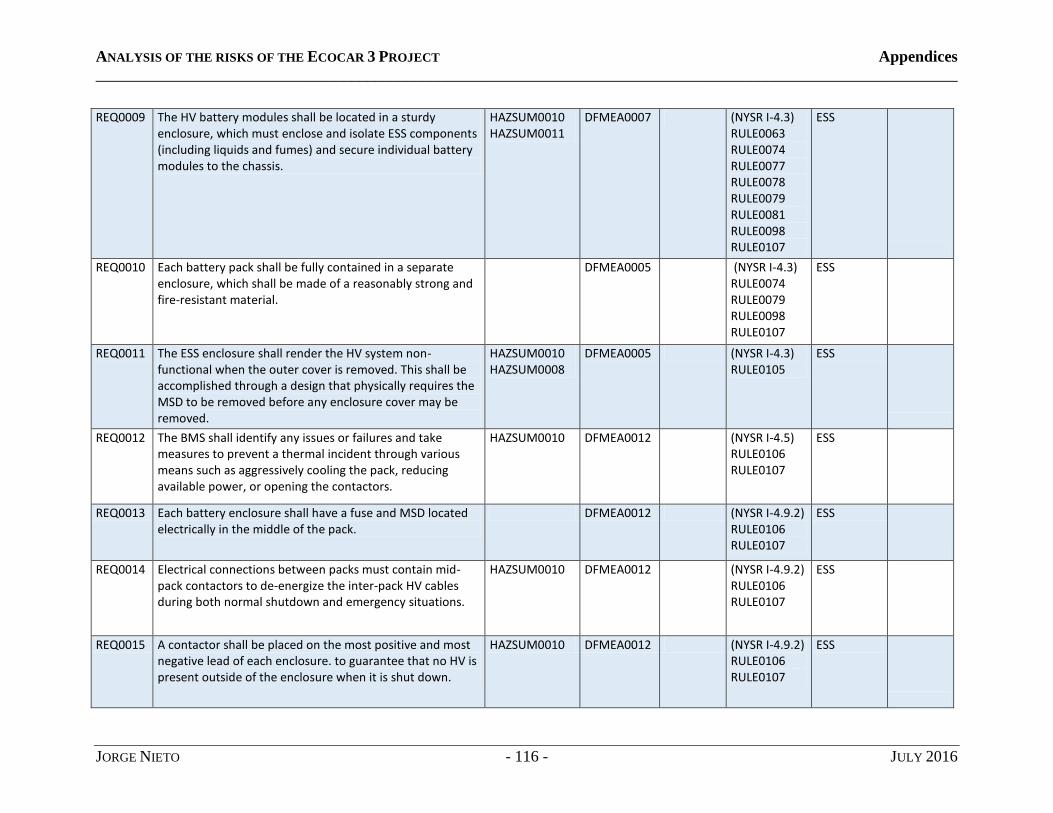
ANALYSIS OF THE RISKS OF THE ECOCAR 3 PROJECT Appendices
____________________________________________________________________________________________________________
JORGE NIETO - 116 - JULY 2016
REQ0009 The HV battery modules shall be located in a sturdy enclosure, which must enclose and isolate ESS components (including liquids and fumes) and secure individual battery modules to the chassis.
HAZSUM0010 HAZSUM0011
DFMEA0007 (NYSR I-4.3) RULE0063 RULE0074 RULE0077 RULE0078 RULE0079 RULE0081 RULE0098 RULE0107
ESS
REQ0010 Each battery pack shall be fully contained in a separate enclosure, which shall be made of a reasonably strong and fire-resistant material.
DFMEA0005 (NYSR I-4.3) RULE0074 RULE0079 RULE0098 RULE0107
ESS
REQ0011 The ESS enclosure shall render the HV system non-functional when the outer cover is removed. This shall be accomplished through a design that physically requires the MSD to be removed before any enclosure cover may be removed.
HAZSUM0010 HAZSUM0008
DFMEA0005 (NYSR I-4.3) RULE0105
ESS
REQ0012 The BMS shall identify any issues or failures and take measures to prevent a thermal incident through various means such as aggressively cooling the pack, reducing available power, or opening the contactors.
HAZSUM0010 DFMEA0012 (NYSR I-4.5) RULE0106 RULE0107
ESS
REQ0013 Each battery enclosure shall have a fuse and MSD located electrically in the middle of the pack.
DFMEA0012 (NYSR I-4.9.2) RULE0106 RULE0107
ESS
REQ0014 Electrical connections between packs must contain mid-pack contactors to de-energize the inter-pack HV cables during both normal shutdown and emergency situations.
HAZSUM0010 DFMEA0012 (NYSR I-4.9.2) RULE0106 RULE0107
ESS
REQ0015 A contactor shall be placed on the most positive and most negative lead of each enclosure. to guarantee that no HV is present outside of the enclosure when it is shut down.
HAZSUM0010 DFMEA0012 (NYSR I-4.9.2) RULE0106 RULE0107
ESS

ANALYSIS OF THE RISKS OF THE ECOCAR 3 PROJECT Appendices
____________________________________________________________________________________________________________
JORGE NIETO - 117 - JULY 2016
REQ0016 Mid-pack contactors shall open immediately upon the activation of the EDS switch. The contactors shall also be controlled using software (i.e., physical switches or buttons cannot be used to manually open or close the mid-pack contactors). However, the opening of any contactor shall not rely on any computer system in the vehicle when the EDS is activated.
HAZSUM0006 HAZSUM0007 HAZSUM0008 HAZSUM0009
(NYSR I-4.9.2) (Section K-1 NYSR)
ESS
REQ0017 For teams with split packs, the existing A123 electrical distribution system (ElDS) cannot be modified. In addition to the required ElDS, at least three additional contactors are required to be added to the split pack design, in addition to contactors present in the existing A123 ElDS Module.
(NYSR I-4.9.4) ESS
REQ0018 Oil pressure sensor shall detect oil pressure within the engine crank case
HAZSUM0019 DFMEA0129 DFMEA0130 DFMEA0131 DFMEA0132 DFMEA0133
ICE
REQ0019 The oil pump shall deliver oil at the nominal flow and pressure as defined by OEM specifications
HAZSUM0018 HAZSUM0019
DFMEA0132 DFMEA0133
ICE
REQ0020 The oil storage container shall resist an impact force of 156lbf (694 N) in case of impact of an object less than or equal to a volume of 27 cubic inches.
HAZSUM0020 HAZSUM0021
ICE
REQ0032 Coolant shall be provided to each IMG between 8 and 25 L/min.
HAZSUM0032 Thermal
REQ0033 Coolant shall be provided to each inverter/APM between 6 and 8 L/min.
HAZSUM0033 Thermal
REQ0034 Coolant for each IMG and inverter/APM shall be VWTL774G13.
HAZSUM0033 Thermal
REQ0035 IMG temperatures shall not exceed 60°C in all electric modes, or 90°C in hybrid modes.
HAZSUM0032 DFMEA0105, DFMEA0106
Thermal
REQ0036 Inverter/APM temperatures shall not exceed 62°C in any mode.
HAZSUM0033 Thermal