es5000 setup guide - secure email gateway - sophos
TRANSCRIPT
Sophos ES5000Email ApplianceSetup Guide1. Preparation2. Rack Installation3. Cabling the Appliance4. Software/Network Setup
Copyright 2000-2011 Sophos Limited. All rights reserved. Sophos is a registered trademark of Sophos Limited and Sophos Group. All other product and company names mentioned are trademarks or registered trademarks of their respective owners.
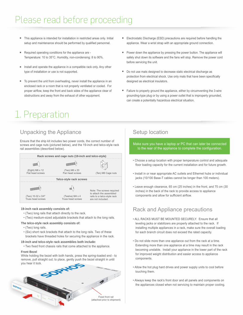
19-inch rack assembly consists of:
The telco-style rack assembly consists of:
19-inch and telco-style rack assemblies both include:
Front Bezel
Rack screws and cage nuts (19-inch and telco-style)
Telco-style rack screws
1. Preparation
Please read before proceeding
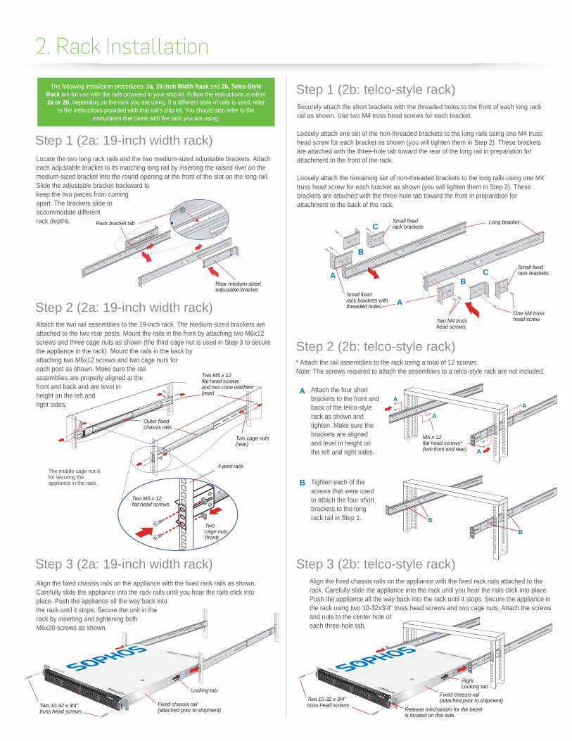
Securely attach the short brackets with the threaded holes to the front of each long rack rail as shown. Use two M4 truss head screws for each bracket.
Loosely attach one set of the non-threaded brackets to the long rails using one M4 truss head screw for each bracket as shown (you will tighten them in Step 2). These brackets are attached with the three-hole tab toward the rear of the long rail in preparation for attachment to the front of the rack.
Loosely attach the remaining set of non-threaded brackets to the long rails using one M4 truss head screw for each bracket as shown (you will tighten them in Step 2). These brackets are attached with the three-hole tab toward the front in preparation for attachment to the back of the rack.
* Attach the rail assemblies to the rack using a total of 12 screws.Note: The screws required to attach the assemblies to a telco-style rack are not included.
Align the fixed chassis rails on the appliance with the fixed rack rails attached to the rack. Carefully slide the appliance into the rack until you hear the rails click into place. Push the appliance all the way back into the rack until it stops. Secure the appliance in the rack using two 10-32x3/4" truss head screws and two cage nuts. Attach the screws and nuts to the center hole of each three-hole tab.
Attach the four short brackets to the front and back of the telco-style rack as shown and tighten. Make sure the brackets are aligned and level in height on the left and right sides.
Tighten each of the screws that were used to attach the four short brackets to the long rack rail in Step 1.
Locate the two long rack rails and the two medium-sized adjustable brackets. Attach each adjustable bracket to its matching long rail by inserting the raised rivet on the medium-sized bracket into the round opening at the front of the slot on the long rail. Slide the adjustable bracket backward to keep the two pieces from coming apart. The brackets slide to accommodate different rack depths.
Align the fixed chassis rails on the appliance with the fixed rack rails as shown. Carefully slide the appliance into the rack rails until you hear the rails click into place. Push the appliance all the way back into the rack until it stops. Secure the unit in the rack by inserting and tightening both M6x20 screws as shown.
Attach the two rail assemblies to the 19-inch rack. The medium-sized brackets are attached to the two rear posts. Mount the rails in the front by attaching two M6x12 screws and three cage nuts as shown (the third cage nut is used in Step 3 to secure the appliance in the rack). Mount the rails in the back by attaching two M6x12 screws and two cage nuts for each post as shown. Make sure the rail assemblies are properly aligned at the front and back and are level in height on the left and right sides.
Small fixedrack brackets
Small fixedrack brackets withthreaded holes
Small fixedrack brackets
Long bracket
A
BC
B
C
A
Two M4 trusshead screws
One M4 trusshead screw
Rear medium-sizedadjustable bracket
Rack bracket tab
The middle cage nut is for securing the appliance in the rack.
*
Two M5 x 12flat head screwsand two cone washers(rear)
Two cage nuts(rear)
Outer fixedchassis rails
4-post rack
Twocage nuts(front)
Two M5 x 12flat head screws
M5 x 12 flat head screws*(two front and rear)
A
A
A
A
B
B
A
B
The following installation procedures: 2a, 19-inch Width Rack and 2b, Telco-Style Rack are for use with the rails provided in your ship kit. Follow the instructions in either 2a or 2b, depending on the rack you are using. If a different style of rails is used, refer
to the instructions provided with that rail’s ship kit. You should also refer to the instructions that came with the rack you are using.
2. Rack Installation
Step 1 (2a: 19-inch width rack)
Step 2 (2a: 19-inch width rack)
Step 3 (2a: 19-inch width rack)
Step 1 (2b: telco-style rack)
Step 2 (2b: telco-style rack)
Step 3 (2b: telco-style rack)
Fixed chassis rail(attached prior to shipment)
Two 10-32 x 3/4"truss head screws
Locking tabTwo 10-32 x 3/4"truss head screws
Fixed chassis rail(attached prior to shipment)
RightLocking tab
Release mechanism for the bezelis located on this side.
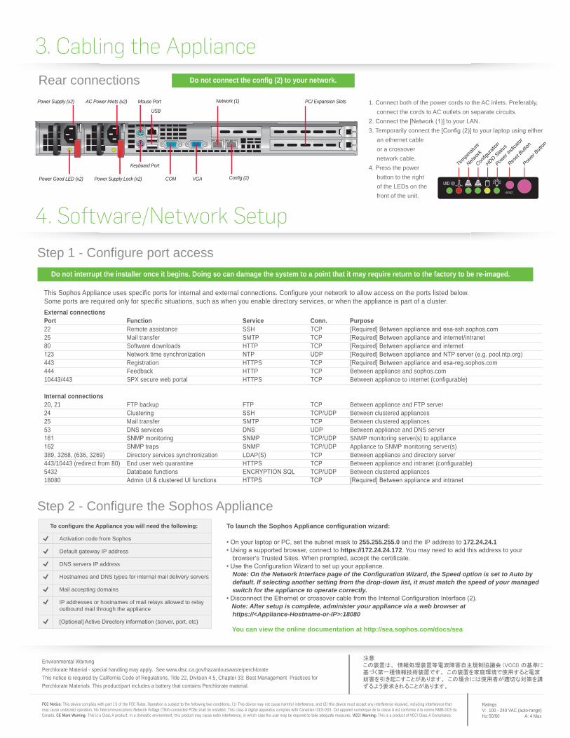
Power Supply Lock (x2)
Power Supply (x2) AC Power Inlets (x2)
Keyboard Port
USB
COM VGA
Network (1)
Config (2)
PCI Expansion SlotsMouse Port
Power Good LED (x2)
FCC Notice: This device complies with part 15 of the FCC Rules. Operation is subject to the following two conditions: (1) This device may not cause harmful interference, and (2) this device must accept any interference received, including interference that may cause undesired operation. No Telecommunications Network Voltage (TNV)-connected PCBs shall be installed. This class A digital apparatus complies with Canadian ICES-003. Cet appareil numérique de la classe A est conforme à la norme NMB-003 du Canada. CE Mark Warning: This is a Class A product. In a domestic environment, this product may cause radio interference, in which case the user may be required to take adequate measures. VCCI Warning: This is a product of VCCI Class A Compliance.
This Sophos Appliance uses specific ports for internal and external connections. Configure your network to allow access on the ports listed below. Some ports are required only for specific situations, such as when you enable directory services, or when the appliance is part of a cluster.
Do not interrupt the installer once it begins. Doing so can damage the system to a point that it may require return to the factory to be re-imaged.
Do not connect the config (2) to your network.
Step 2 - Configure the Sophos Appliance
Step 1 - Configure port access
3. Cabling the ApplianceRear connections
Environmental WarningPerchlorate Material - special handling may apply. See www.dtsc.ca.gov/hazardouswaste/perchlorateThis notice is required by California Code of Regulations, Title 22, Division 4.5, Chapter 33: Best Management Practices for Perchlorate Materials. This product/part includes a battery that contains Perchlorate material.
RatingsV: 100 - 240 VAC (auto-range)Hz: 50/60 A: 4 Max
You can view the online documentation at http://sea.sophos.com/docs/sea
To launch the Sophos Appliance configuration wizard:
255.255.255.0 and the IP address to 172.24.24.1 https://172.24.24.172. You may need to add this address to your
browser's Trusted Sites. When prompted, accept the certificate.
Note: On the Network Interface page of the Configuration Wizard, the Speed option is set to Auto by default. If selecting another setting from the drop-down list, it must match the speed of your managed switch for the appliance to operate correctly.
Note: After setup is complete, administer your appliance via a web browser at https://<Appliance-Hostname-or-IP>:18080
Activation code from Sophos
Default gateway IP address
DNS servers IP address
Hostnames and DNS types for internal mail delivery servers
Mail accepting domains
IP addresses or hostnames of mail relays allowed to relay outbound mail through the appliance
(server, port, etc)
To configure the Appliance you will need the following:
External connectionsPort Function Service Conn. Purpose22 Remote assistance SSH TCP 25 Mail transfer SMTP TCP 80 Software downloads HTTP TCP
443 Registration HTTPS TCP 444 Feedback HTTP TCP Between appliance and sophos.com10443/443 SPX secure web portal HTTPS TCP Between appliance to internet (configurable)
Internal connections20, 21 FTP backup FTP TCP Between appliance and FTP server
Between clustered appliances25 Mail transfer SMTP TCP Between clustered appliances
Between appliance and DNS serverSNMP monitoring server(s) to applianceAppliance to SNMP monitoring server(s)
389, 3268, (636, 3269) Directory services synchronization LDAP(S) TCP Between appliance and directory server 443/10443 (redirect from 80) End user web quarantine HTTPS TCP Between appliance and intranet (configurable)5432 Between clustered appliances18080
4. Software/Network Setup
1. Connect both of the power cords to the AC inlets. Preferably, connect the cords to AC outlets on separate circuits.
your LAN.3. Temporarily connect the
an ethernet cable or a crossover network cable.
4. Press the power button to the right of the LEDs on the front of the unit.
Reset
Button
Power
Button
Power
Indica
tor
HDD Stat
us
Config
uratio
n
Network
Tempe
rature