es 203 700 - v1.1.1 - environmental engineering (ee
TRANSCRIPT

ETSI ES 203 700 V1.1.1 (2021-02)
Environmental Engineering (EE); Sustainable power feeding solutions for 5G network
ETSI STANDARD

ETSI
ETSI ES 203 700 V1.1.1 (2021-02) 2
Reference DES/EE-0269
Keywords 5G, cable, energy efficiency, hybrid, power,
remote, sustainability
ETSI
650 Route des Lucioles F-06921 Sophia Antipolis Cedex - FRANCE
Tel.: +33 4 92 94 42 00 Fax: +33 4 93 65 47 16
Siret N° 348 623 562 00017 - NAF 742 C
Association à but non lucratif enregistrée à la Sous-Préfecture de Grasse (06) N° 7803/88
Important notice
The present document can be downloaded from: http://www.etsi.org/standards-search
The present document may be made available in electronic versions and/or in print. The content of any electronic and/or print versions of the present document shall not be modified without the prior written authorization of ETSI. In case of any
existing or perceived difference in contents between such versions and/or in print, the prevailing version of an ETSI deliverable is the one made publicly available in PDF format at www.etsi.org/deliver.
Users of the present document should be aware that the document may be subject to revision or change of status. Information on the current status of this and other ETSI documents is available at
https://portal.etsi.org/TB/ETSIDeliverableStatus.aspx
If you find errors in the present document, please send your comment to one of the following services: https://portal.etsi.org/People/CommiteeSupportStaff.aspx
Copyright Notification
No part may be reproduced or utilized in any form or by any means, electronic or mechanical, including photocopying and microfilm except as authorized by written permission of ETSI.
The content of the PDF version shall not be modified without the written authorization of ETSI. The copyright and the foregoing restriction extend to reproduction in all media.
© ETSI 2021.
All rights reserved.
DECT™, PLUGTESTS™, UMTS™ and the ETSI logo are trademarks of ETSI registered for the benefit of its Members. 3GPP™ and LTE™ are trademarks of ETSI registered for the benefit of its Members and
of the 3GPP Organizational Partners. oneM2M™ logo is a trademark of ETSI registered for the benefit of its Members and
of the oneM2M Partners. GSM® and the GSM logo are trademarks registered and owned by the GSM Association.

ETSI
ETSI ES 203 700 V1.1.1 (2021-02) 3
Contents
Intellectual Property Rights ................................................................................................................................ 5
Foreword ............................................................................................................................................................. 5
Modal verbs terminology .................................................................................................................................... 5
Executive summary ............................................................................................................................................ 5
Introduction ........................................................................................................................................................ 6
1 Scope ........................................................................................................................................................ 7
2 References ................................................................................................................................................ 7
2.1 Normative references ......................................................................................................................................... 7
2.2 Informative references ........................................................................................................................................ 8
3 Definition of terms, symbols and abbreviations ....................................................................................... 9
3.1 Terms .................................................................................................................................................................. 9
3.2 Symbols .............................................................................................................................................................. 9
3.3 Abbreviations ..................................................................................................................................................... 9
4 5G networks ........................................................................................................................................... 10
4.1 5G Network general description ....................................................................................................................... 10
4.2 Cells coverage and impacts on powering strategy ............................................................................................ 11
4.3 Type of 5G network and impacts on power load, power profile and feeding solution ..................................... 14
5 Powering solutions ................................................................................................................................. 16
5.0 General ............................................................................................................................................................. 16
5.1 Convergence and Core Room Power Supply ................................................................................................... 16
5.1.1 Scenario 1: -48 V DC Power Supply Solution ............................................................................................ 16
5.1.2 Scenario 2: up to 400 V DC Power Supply Solution .................................................................................. 17
5.1.3 5G Power Supply Solution for aggregation and core equipment room ...................................................... 17
5.2 Impact of 5G in C-RAN&D-RAN Sites ........................................................................................................... 18
5.2.1 Changes due to 5G implementation ............................................................................................................ 18
5.2.2 Construction and Modernization Challenges Posed by 5G Network Evolution ......................................... 18
5.2.3 Problems to Be Addressed by 5G Power Systems ...................................................................................... 19
5.2.3.1 Low Cost Deployment .......................................................................................................................... 19
5.2.3.2 Fast Construction .................................................................................................................................. 19
5.2.3.3 Efficient and Energy Saving ................................................................................................................. 19
5.2.3.4 Smooth Evolution ................................................................................................................................. 20
5.2.3.5 Simple O&M ......................................................................................................................................... 20
5.2.4 C-RAN & D-RAN Powering Scenario ....................................................................................................... 20
5.2.4.1 Networking diagram of powering scenario ........................................................................................... 20
5.2.5 5G Power Solution for C-RAN&D-RAN site ............................................................................................. 21
5.2.6 Intelligent Features for C-RAN&D-RAN site ............................................................................................ 23
5.2.6.1 Intelligent Peak Shaving ....................................................................................................................... 23
5.2.6.2 Advance Sleep/Hibernation Mode function .......................................................................................... 25
5.3 Intelligent Management .................................................................................................................................... 25
5.3.0 General ........................................................................................................................................................ 25
5.3.1 Power availability Management ................................................................................................................. 25
5.3.2 SEE Management ....................................................................................................................................... 26
5.3.3 Remote Maintenance .................................................................................................................................. 26
5.3.4 intelligent security ...................................................................................................................................... 26
5.3.5 Intelligent Energy Storage System .............................................................................................................. 27
5.4 Renewable energy solution for 5G base stations .............................................................................................. 27
5.5 Hybrid architecture scenario, with integration of power and optical networks ................................................ 28
6 Energy Efficiency ................................................................................................................................... 32
6.1 Power equipment energy efficiency ................................................................................................................. 32
6.2 NE static and dynamic power requirement management and impact on powering .......................................... 32
7 Dependability, reliability and maintenance ............................................................................................ 32

ETSI
ETSI ES 203 700 V1.1.1 (2021-02) 4
8 Environmental impact ............................................................................................................................ 33
Annex A (informative): Which power and where for 5G cells ........................................................... 34
Annex B (informative): Method of optimization of equipment, power and energy ......................... 35
Annex C (informative): Example of powering requirement definition on site and remote powering area ................................................................................................. 37
Annex D (informative): Example of required output voltage variation under correlation models between different load and different cable length.......................... 38
Annex E (informative): Digital Reconfigurable Battery solution for 5G base stations.................... 40
Annex F (informative): Bibliography ................................................................................................... 42
History .............................................................................................................................................................. 43

ETSI
ETSI ES 203 700 V1.1.1 (2021-02) 5
Intellectual Property Rights
Essential patents
IPRs essential or potentially essential to normative deliverables may have been declared to ETSI. The information pertaining to these essential IPRs, if any, is publicly available for ETSI members and non-members, and can be found in ETSI SR 000 314: "Intellectual Property Rights (IPRs); Essential, or potentially Essential, IPRs notified to ETSI in respect of ETSI standards", which is available from the ETSI Secretariat. Latest updates are available on the ETSI Web server (https://ipr.etsi.org/).
Pursuant to the ETSI IPR Policy, no investigation, including IPR searches, has been carried out by ETSI. No guarantee can be given as to the existence of other IPRs not referenced in ETSI SR 000 314 (or the updates on the ETSI Web server) which are, or may be, or may become, essential to the present document.
Trademarks
The present document may include trademarks and/or tradenames which are asserted and/or registered by their owners. ETSI claims no ownership of these except for any which are indicated as being the property of ETSI, and conveys no right to use or reproduce any trademark and/or tradename. Mention of those trademarks in the present document does not constitute an endorsement by ETSI of products, services or organizations associated with those trademarks.
Foreword This ETSI Standard (ES) has been produced by ETSI Technical Committee Environmental Engineering (EE).
Modal verbs terminology In the present document "shall", "shall not", "should", "should not", "may", "need not", "will", "will not", "can" and "cannot" are to be interpreted as described in clause 3.2 of the ETSI Drafting Rules (Verbal forms for the expression of provisions).
"must" and "must not" are NOT allowed in ETSI deliverables except when used in direct citation.
Executive summary The present document defines power feeding solutions for 5G, converged wireless and wireline access equipment and network, taking into consideration their enhanced requirements on service availability and reliability, the new deployment scenarios, together with the environmental impact of the proposed solutions.
The minimum requirements of different solutions including power feeding structures, components, backup, safety requirements, environmental conditions are also defined.
The present document is applicable to powering of both mobile and fixed access network elements, in particular on equipment that have similar configurations and needs.

ETSI
ETSI ES 203 700 V1.1.1 (2021-02) 6
Introduction Mobile and fixed networks are evolving towards ultra-broadband and, with 5G, are going to converge. The use of much broader frequency ranges, up to 60 GHz, where radio propagation is an issue, is going to impact the network deployment topologies. In particular, the use of higher frequencies and the need to cover hot/black spots and indoor locations, will make it necessary to deploy much denser amount of radio nodes.
5G is introducing major improvements on Massive MIMO, IoT, low latency, unlicensed spectrum, and with V2x for the vehicular market. Support of some of these services will have a relevant effect on the power ratings and the energy consumption at the radio base station.
A major new service area of 5G impacting the powering and backup will be the URLLC (Ultra Reliable Low Latency Communication) as its support will increase the service availability demands by many orders of magnitude. Supporting such high availability goals will be partly reached through redundant network coverage, but a main support will have to come through newly designed powering architectures. This will be made even more challenging as 5G will require the widespread introduction of distributed small cells. ETSI TS 110 174-2-2 [i.5] analyses the implications and indicates possible solutions to fulfil such high demanding availability goals.
There is a need to define sustainable and smart powering solutions, able to adapt to the present mobile network technologies and able to evolve to adapt to their evolution. The flexibility would be needed at level of power interface, power consumption, architecture tolerant to power delivery point changes and including control-monitoring.
This means that it should include from the beginning appropriate modularity and reconfiguration features for local powering and energy storage and for remote powering solutions including power lines sizing, input and output conversion power and scalable sources.
The present document was developed jointly by ETSI TC EE and ITU-T Study Group 5. It is published respectively by ITU and ETSI as Recommendation ITU-T L.1210 [i.7] and ETSI ES 203 700 (the present document), which are technically-equivalent.

ETSI
ETSI ES 203 700 V1.1.1 (2021-02) 7
1 Scope The present document defines power feeding solutions for 5G, converged wireless and wireline access equipment and network, taking into consideration their enhanced requirements on service availability and reliability, the new deployment scenarios, together with the environmental impact of the proposed solutions.
The minimum requirements of different solutions including power feeding structures, components, backup, safety requirements, environmental conditions are also defined.
The present document is applicable to powering of both mobile and fixed access network elements, in particular on equipment that have similar configurations and needs.
The future development of 5G networks will create a new scenario in which the density of radio cells will increase considerably, together with the increase of wireline network equipment that are going to be installed in the vicinity to the users, thereby creating the need to define new solutions for powering that will be environmentally friendly, sustainable, dependable, smart and visible remotely.
The -48 V DC, up to 400 V DC local and remote power solutions defined respectively in ETSI EN 300 132-2 [2], ETSI EN 302 099 [i.10] and ETSI EN 300 132-3-1 [3] or Recommendation ITU-T L.1200 [i.13] will be considered as the standards in force for power facilities, together with IEEE 802.3TM [i.18] (PoE).
2 References
2.1 Normative references References are either specific (identified by date of publication and/or edition number or version number) or non-specific. For specific references, only the cited version applies. For non-specific references, the latest version of the referenced document (including any amendments) applies.
Referenced documents which are not found to be publicly available in the expected location might be found at https://docbox.etsi.org/Reference/.
NOTE: While any hyperlinks included in this clause were valid at the time of publication, ETSI cannot guarantee their long term validity.
The following referenced documents are necessary for the application of the present document.
[1] ETSI EN 300 132-1 (V2.1.1) (03-2019): "Environmental Engineering (EE); Power supply interface at the input to Information and Communication Technology (ICT) equipment; Part 1: Alternating Current (AC)".
[2] ETSI EN 300 132-2 (V2.6.1) (04-2019):"Environmental Engineering (EE); Power supply interface at the input of Information and Communication Technology (ICT) equipment; Part 2: -48 V Direct Current (DC)".
[3] ETSI EN 300 132-3-1 (V2.1.1) (02-2012): "Environmental Engineering (EE); Power supply interface at the input to telecommunications and datacom (ICT) equipment; Part 3: Operated by rectified current source, alternating current source or direct current source up to 400 V; Sub-part 1: Direct current source up to 400 V".
[4] ETSI ES 203 199 (V1.3.1) (02-2015): "Environmental Engineering (EE); Methodology for environmental Life Cycle Assessment (LCA) of Information and Communication Technology (ICT) goods, networks and services".
[5] Recommendation ITU-T L.1410 (12/2014): "Methodology for environmental life cycle assessments of information and communication technology goods, networks and services".

ETSI
ETSI ES 203 700 V1.1.1 (2021-02) 8
2.2 Informative references References are either specific (identified by date of publication and/or edition number or version number) or non-specific. For specific references, only the cited version applies. For non-specific references, the latest version of the referenced document (including any amendments) applies.
NOTE: While any hyperlinks included in this clause were valid at the time of publication, ETSI cannot guarantee their long term validity.
The following referenced documents are not necessary for the application of the present document but they assist the user with regard to a particular subject area.
[i.1] Recommendation ITU-T Q.1743 (09/2016): "IMT-Advanced references to Release 11 of LTE-Advanced evolved packet core network".
[i.2] ETSI ES 202 336-12: "Environmental Engineering (EE); Monitoring and control interface for infrastructure equipment (power, cooling and building environment systems used in telecommunication networks); Part 12: ICT equipment power, energy and environmental parameters monitoring information model".
[i.3] ETSI EN 301 605 (V1.1.1) (2013-10): "Environmental Engineering (EE); Earthing and bonding of 400 V DC data and telecom (ICT) equipment".
[i.4] ETSI TS 122 261: "5G; Service requirements for next generation new services and markets (3GPP TS 22.261)".
[i.5] ETSI TS 110 174-2-2: "Access, Terminals, Transmission and Multiplexing (ATTM); Sustainable Digital Multiservice Cities; Broadband Deployment and Energy Management; Part 2: Multiservice Networking Infrastructure and Associated Street Furniture; Sub-part 2: The use of lamp-posts for hosting sensing devices and 5G networking".
[i.6] Recommendation ITU-T K.64 (06/2016): "Safe working practices for outside equipment installed in particular environments".
[i.7] Recommendation ITU-T L.1210: "Sustainable power feeding solutions for 5G networks".
[i.8] EN 50173-1: "Information technology - Generic cabling systems - Part 1: General requirement" (produced by CENELEC).
[i.9] IEEE 802.3cgTM: "IEEE Approved Draft Standard for Ethernet Amendment 5: Physical Layer Specifications and Management Parameters for 10 Mb/s Operation and Associated Power Delivery over a Single Balanced Pair of Conductors".
[i.10] ETSI EN 302 099 (V2.1.1) (08-2014): "Environmental Engineering (EE); Powering of equipment in access network".
[i.11] ETSI TS 103 553-1: "Environmental Engineering (EE); Innovative energy storage technology for stationary use; Part 1: Overview".
[i.12] Recommendation ITU-T L.1001 (11/2012): "External universal power adapter solutions for stationary information and communication technology devices".
[i.13] Recommendation ITU-T L.1200 (05/2012): "Direct current power feeding interface up to 400 V at the input to telecommunication and ICT equipment".
[i.14] Recommendation ITU-T L.1220 (08/2017): "Innovative energy storage technology for stationary use - Part 1: Overview of energy storage".
NOTE: Available at https://www.itu.int/ITU-T/recommendations/rec.aspx?rec=13283.
[i.15] Recommendation ITU-T L.1221 (11/2018): "Innovative energy storage technology for stationary use - Part 2: Battery".
[i.16] Recommendation ITU-T L.1222 (05/2018): "Innovative energy storage technology for stationary use - Part 3: Supercapacitor technology".

ETSI
ETSI ES 203 700 V1.1.1 (2021-02) 9
[i.17] Recommendation ITU-T L.1350 (10/2016): "Energy efficiency metrics of a base station site".
[i.18] IEEE 802.3TM-2018: "IEEE Standard for Ethernet".
[i.19] IEEE 802.3btTM-2018: "IEEE Standard for Ethernet Amendment 2: Physical Layer and Management Parameters for Power over Ethernet over 4 pairs".
[i.20] A Survey of 5G Network: Architecture and Emerging Technologies.
NOTE: Available at https://ieeexplore.ieee.org/document/7169508.
[i.21] 5G Frequency bands: Spectrum Allocations for Next-Gen LTE.
NOTE: Available at https://www.cablefree.net/wirelesstechnology/4glte/5g-frequency-bands-lte/.
3 Definition of terms, symbols and abbreviations
3.1 Terms For the purposes of the present document, the following terms apply:
cell: radio network object that can be uniquely identified by a user equipment from a (cell) identification that is broadcasted over a geographical area from one UTRAN or GERAN access point
NOTE 1: A Cell in UTRAN is either FDD or TDD mode.
NOTE 2: Defined in Recommendation ITU-T Q.1743 [i.1].
cloud RAN: RAN functions are partially or completely centralizing with two additional key features: pooling of baseband/hardware resources, and virtualization through general-purpose processors
distributed RAN: network development where RAN processing is fully performed at the site as in 4G
macro cells: outdoor cells with a large cell radius
NOTE: Defined in Recommendation ITU-T Q.1743 [i.1].
micro cells: small cells
NOTE: Defined in Recommendation ITU-T Q.1743 [i.1].
pico cells: cells, mainly indoor cells, with a radius typically less than 50 metres
NOTE: Defined in Recommendation ITU-T Q.1743 [i.1]
3.2 Symbols Void.
3.3 Abbreviations For the purposes of the present document, the following abbreviations apply:
5G Fifth Generation AAU Active Antenna Unit AC Alternating Current AI Artificial Intelligence BBU Base Band Unit BCS Battery Control System BMS Battery Management System BS Base Station

ETSI
ETSI ES 203 700 V1.1.1 (2021-02) 10
C-RAN Centralized or Cloud RAN DC Direct Current
NOTE: Also when used as a suffix to units of measurement.
DOD Deep of Discharge DP Distribution Point D-RAN Distributed RAN DSLAM Digital Subscriber Line Access Multiplier EV Electrical Vehicle FWA Fixed Wireless Access GND GrouND GPON Gigabit Passive Optical Network Hetnets Heterogeneous network ICT Information Communication Telecommunication IoT Internet of Things LFP Lithium Iron Phosphate MEC Multi-access Edge Computing MIMO Multi Input Multi Output mmWaves millimetric Waves MPPT Maximum Power Point Tracking NE Network Element OS Optical Splitter PAV Power Available Value PN Power Node PON Passive Optical Network PS Power Splitter PSU Power Supply Unit PTU Power Transmitter Unit PV PhotoVoltaic PVC PolyVinyl Chloride RAN Radio Access Network REN Renewable ENergy RF Radio Frequency RRH Remote Radio Head RRU Remote Radio Unit SEE Site Energy Efficiency SELV Safety Extra Low Voltage SOC Status Of Charge SOH Status Of Health TDD Time Division Duplex TTM Time To Market URLLC Ultra Reliable Low Latency Communication UTRAN Universal Terrestrial Radio Access Network UV UltraViolet
4 5G networks
4.1 5G Network general description Figure 1 is presenting a general end to end schematics of 5G network to be powered.
It includes stationary and mobile equipment:
• Macro cell equipment BS for wide coverage. In most cases, they will be located in the same sites as the macro BS of the previous mobile generations. The increased energy demand and the much higher availability need of the 5G equipment will pose tough challenges to the powering infrastructure and will likely require its major upgrade both on the power capabilities and the backup duration.

ETSI
ETSI ES 203 700 V1.1.1 (2021-02) 11
• Small cell, to cover small geographical area in indoor/outdoor applications, typically to satisfy data traffic hot-spots, black-spots and to deliver services at very high frequencies (e.g. mmWaves) that could not be supported just through macro BS installations. Small cells can be subdivided into:
- Micro cell - normally installed outdoors. Designed to support large number of users in high data traffic areas, to solve coverage issues and to support very high frequency deployment. Capable to cover medium/large cells size and suitable for application like smart cities, smart metro, etc.
- Pico cell - normally installed indoors. Suitable for enterprises, shopping centres, stadiums applications, for extended network coverage and data throughput.
- Femto cell - basically small mobile base stations designed to provide extended coverage for residential and SoHo applications. Poor signal strength from mobile operator's base stations can be solved using Femtocell implementation. Femtocells are primarily introduced to offload network congestion, extend coverage and increase data capacity to indoor users.
• IoT devices and concentrators.
• In network cloud distribution including edge computing.
Also Fixed Wireless Access (FWA) radio access solutions, typically in point-to-multipoint configuration with coverage across macro and small cells schemes, will contribute to the evolution of ultra-broadband future networks.
Source: https://ieeexplore.ieee.org/document/7169508 [i.20]. Figure 1: General principle of a 5G cellular network architecture with interconnectivity among
the different emerging technologies like Massive MIMO network, Cognitive Radio
4.2 Cells coverage and impacts on powering strategy In the 4G era, a base station covers a radius of hundreds of metres, while a 5G base station operating at mmWave may cover only 20 to 40 m, needing a much higher number of equipment to be spread-out in the field to guarantee appropriate coverage. More dense deployment will also be needed to cover high traffic areas (e.g. stadiums) and indoor locations. That could result in much higher network development complexity and costs. In addition, the deployment of additional base stations is difficult and the site resources are not easy to obtain. Therefore, 5G networks will see a major development of small cells, in the form of small base stations as the basic unit for ultra-intensive networking, that is, small base stations dense deployment. In the future, the most likely deployment mode for 5G base station construction will be low-frequency wide area coverage (macro base station) + high-frequency deep coverage (micro base station), as shown in Figures 2(a) to 2(c).

ETSI
ETSI ES 203 700 V1.1.1 (2021-02) 12
Figure 2(a): Deployment mode of the 5G base station
Figure 2(b): Micro base station
Figure 2(c): Macro base station
The typical electrical power demand for Radio Base Stations (macro cell, micro cell and pico or femto cell), with correlation to aggregated RF power, is available in Table 1, together with power needs of IoT, as they could be based on powering paradigms similar to those of the Small Cells.

ETSI
ETSI ES 203 700 V1.1.1 (2021-02) 13
Table 1: Powering related characteristics of radio base station, Small Cells and IoT
EQUIPMENT
INDOORS INDOORS OUTDOORS TYP MAX BATTERY
Local
mains
Remote
power PoE
mimimum
BACKUP time
Wireline /
Wireless Connection flavour MIN MAX
Private
premises
Public sites
and
enterprises (W) (W)
Duration
(years) (W) (W)
WIRELESS
COMPLEX MACRO BASE STATION (e.g.
2/3/4/5G - multiple freq, massive MIMO
and multiple operators)
X 8000 24000 X
YES
many
hours
Wireline Optical many
hundreds
SIMPLE MACRO BASE STATION (e.g.
2/3/4G - single freq and single operator)X 3000 6000 X
YES
few hours
Wireline
/ wireless
Optical / mmWave
/ high speed
broadband
few
hundreds
MICROCELLS X 30 250 X Xadvised
minutesWireline
Optical / high speed
broadband1 20
PICOCELLS (including FWA nodes) X 10 50 X Xadvised
minutesWireline ETH/Optical 0,1 1
FEMTOCELLS X 5 20 X NO Wireline Any Broadband 0,01 0,1
WIRELINE
VDSL2 DSLAMs Cabinets 150 250 X Xadvised
minutesWireline Optical
G.FAST Cabinets 25 40 X Wireline Optical
IoT
Gas & water sensing, metering X very low 10 Wireless LP WAN
Surveillance camera X X 5 20 X X X NO Wireline Any Broadband
Environmental sensing (CO2, NOX, noise,
particulate …) X 2 10 X NO Wireless LP WAN
INSTALLATION POW. CONSUMPTION Backhauling connection Aggregated RF powerPOWERING TYPE
ETSI
ETSI ES 203 700 V1.1.1 (2021-02) 14
The most appropriate power architecture will depend on the site type, their coverage, location and distance from grid or from remote power sources.
The power source selection will depend on:
• local grid availability or connection cost and lead time , compared to remote powering;
• services availability (continuity) requirements;
• need to share the power infrastructure between operators;
• availability of renewable energy e.g. photovoltaic;
• possible power connection shared with other user such as street Lighting equipment or electric car charging stations, etc.
Power Interface for each case are described in clause 5.
A possible solution using street lamp post for small cell deployment can be found in ETSI TS 110 174-2-2 [i.5].
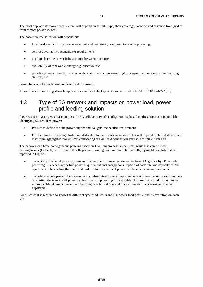
4.3 Type of 5G network and impacts on power load, power profile and feeding solution
Figures 2 (a) to 2(c) give a base on possible 5G cellular network configurations, based on these figures it is possible identifying 5G required power:
• Per site to define the site power supply and AC grid connection requirement.
• For the remote powering cluster site dedicated to many sites in an area. This will depend on line distances and maximum aggregated power limit considering the AC grid connection available to this cluster site.
The network can have homogeneous patterns based on 1 to 3 macro cell BS per km², while it is can be more heterogeneous (HetNets) with 10 to 100 cells per km² ranging from macro to femto cells, a possible evolution it is reported in Figure 3:
• To establish the local power system and the number of power access either from AC grid or by DC remote powering it is necessary define power requirement and energy consumption of each site and capacity of NE equipment. The cooling thermal limit and availability of local power can be a determinant parameter.
• To define remote power, the location and configuration is very important as it will need to reuse existing pairs or existing ducts to install power cable (or hybrid powering/optical cable). In case this would turn out to be impracticable, it can be considered building new buried or aerial lines although this is going to be more expensive.
For all cases it is required to know the different type of 5G cells and NE power load profile and its evolution on each site.

ETSI
ETSI ES 203 700 V1.1.1 (2021-02) 15
Figure 3: Evolution of 5G cellular network configurations to HetNets
Figure 4 reports an estimation of possible power request for a full radio site containing different band for different development of 5G technologies.
Figure 4: Estimate radio base station power site rating

ETSI
ETSI ES 203 700 V1.1.1 (2021-02) 16
5 Powering solutions
5.0 General The present clause 5 defines requirements on 5G powering considering different site topology.
The 5G NE power interface voltages commonly used are listed below:
• ETSI EN 300 132-2 [2] interface A for 40,5 to 72 V DC powering. The equipment of the Remote radio Unit (RRU/AAU) is designed to work with the most common powering architectures found in telecommunications sites with operating voltages in the range -40,5 to 72 V DC. Feeding DC voltages within such range enables the use of common and lower cost equipment. The use of voltages below 60 V DC incurs far less demanding safety requirements and eases installation and maintenance. However, within legacy telecommunications cabling, the need to limit the power losses resulting from the relatively high currents required restricts the maximum reach of this type of solution.
NOTE: ETSI EN 300 132-2 [2] defines as nominal voltage 48 V DC and in an annex a nominal voltage of 60 V DC.
• ETSI EN 300 132-1 [1] interface A1 for AC powering.
• Recommendation ITU-T L.1200 [i.13] or ETSI EN 300 132-3-1 [3] interface P for up to 400 V DC powering.
• Recommendation ITU-T L.1001 [i.12] for low DC voltage 5 V or 12 V e.g. used for little 5G femto or pico cells.
• IEEE 802-3 [i.18] allows the same cable to provide both data connection and electric power to the devices. Sometimes referred to as Power over Ethernet (PoE), Recommendation ITU-T L.1220 [i.14] specifies remote power feeding over 2 and 4 balanced pairs of cables of Category 5 and above (as specified in EN 50173-1 [i.8]. In addition, IEEE 802.3cg [i.9] will specifies remote power feeding of a variety of 1 pair balanced cables. Both implementations use voltages of below 60 V DC. The power feeding of IEEE 802.3bt [i.19] provides up to 71 W at the remote equipment using 4 balance pairs at maximum distance of 100 m while IEEE 802.3cg [i.9] delivers 14 W at 300 m and 2 W at 1 000 m.
The following clauses consider the power requirement for:
• Aggregation and Core equipment room.
• C-RAN and D-RAN site.
5.1 Convergence and Core Room Power Supply
5.1.1 Scenario 1: -48 V DC Power Supply Solution
Figure 5 reports a power feeding distribution in the case to use a -48 V DC power supply solution. The system shall support -57 V DC power supply, which is defined in ETSI EN 300 132-2 [2] that the upper limit value of a -48 V DC system should be -57 V DC.

ETSI
ETSI ES 203 700 V1.1.1 (2021-02) 17
NOTE 1: AC2 can be a Diesel generator or any other type of emergency generator. NOTE 2: Energy storage in some case can be a fuel cell. NOTE 3: In some case WIND generator can be used to replace solar (PV) or in conjunction with them.
Figure 5: Network diagram of -48 V DC power supply solution
5.1.2 Scenario 2: up to 400 V DC Power Supply Solution
Figure 6 reports a power feeding distribution in the case to use an up to 400 V DC power supply solution. The up to 400 V DC system decreases voltage drop on cable and allows a much less amount of cable size, which reduces cable investment and makes it easier to be installed.
NOTE 1: AC2 can be a Diesel generator or any other type of emergency generator. NOTE 2: Energy storage in some case can be a fuel cell. NOTE 3: In some case WIND generator can be used to replace solar (PV) or in conjunction with them.
Figure 6: Networking diagram of the up to 400 V DC power supply solution
5.1.3 5G Power Supply Solution for aggregation and core equipment room
Considering the changes in the power supply requirements of the 5G network for the core room and future evolution, the proposed power solution should have the following features:
1) Input and output voltage:
- Multiple energy input and multiple voltage output to meet ICT integration needs.
- Multi-input: multi-type of AC energy inputs and solar (optional WIND) energy input.
- Multi-output: 230 Vac, 400 V DC and other voltages output by adapting different power modules.
2) Lithium batteries:
- Lithium replacing lead-acid battery is expected to reduce more than 60 % footprint to meet the space requirement of business expansion. Furthermore, the low dependency of lithium to the room temperature allows installing it in ICT rooms.
- Lithium battery meets anti-fire requirement:
1) battery material: at current stage of technology lithium iron phosphate is required for safety concern;

ETSI
ETSI ES 203 700 V1.1.1 (2021-02) 18
2) safety management: abnormality of external charging voltage and current does not affect battery safety work;
3) flame-retardant: materials used in battery pack shall meet UL 94-V0;
4) fire control: When the cell has a fire problem, flame inside the battery pack shall not leak outside, and the temperature of battery pack outer surface shall not exceed 120 °C.
- Lithium discharge capability in parallel: When the modules are connected in parallel, the maximum discharge capacity can reach P×N without output power derating, P is the maximum discharge capacity of a single battery, and N is the number of batteries in parallel.
3) Green and efficient:
- The system allows green energy (such as solar energy) access smoothly and gives it priority.
- The system can output -57 V DC, which saves cable loss by 10 % ~ 20 %.
4) Digital and intelligent management: the power system and the room environment information such as humidity and temperature can be managed by a remote network management system.
5) Additional Safety requirements: safety functions such as safe start up, insulation monitor and AC utility monitor are needed for enhancing the system safety.
Description:
• Safe start up: system automatically checks the cable route and remote load correctness in a safe voltage mode, then outputs a voltage up to 400 V DC for remote load.
• Insulation monitor for 400 V DC: monitor system insulation impedance, including + to GND and - to GND. Triggering alarm or cutting output when impedance is lower than defined threshold.
• AC utility monitor: detect AC voltage on the system. Triggering alarm or cutting output when impedance is lower than defined threshold.
5.2 Impact of 5G in C-RAN&D-RAN Sites
5.2.1 Changes due to 5G implementation
The power consumption of 5G increases significantly compared with that of the 4G. In the 5G era, for example, the estimated maximum power consumption the 64T64R AAU could be 1 000 W 1 400 W, and the estimated maximum power consumption of the BBU could be about 1 200 W to 1 500 W including also actual 3G and 4G cards.
Multiple bands in one site will be the typical configuration in 5G. The proportion of sites with more than five bands will increase from 3 % in 2016 to 45 % in 2023. As a result, the maximum power consumption of a typical site will exceed 10 kW, while in a site where there are more than 10 bands, the power consumption will exceed 20 kW. In the multi-carrier sharing scenarios, this figure will be doubled.
5.2.2 Construction and Modernization Challenges Posed by 5G Network Evolution
• Grid Reconstruction Challenges:
- Grid connection sizing of the existing sites may be insufficient due to power consumption increasing when 5G accesses. Grid modernization is expensive and greatly slows down the pace of 5G deployment.
- Over 30 % of global sites needs grid modernization. The time to modernize the grid is about one year per site.

ETSI
ETSI ES 203 700 V1.1.1 (2021-02) 19
• DC Power Distribution Challenges:
- A 5G single-band power distribution requires at least two 100 A inputs (or four 32 A & three 63 A inputs). For example, over 75 % DC circuit breakers of a carrier in China are 63 A or smaller, which is insufficient for 5G access.
- In a remote scenario with high-power AAU, huge voltage drop on cable would result in insufficient voltage input for AAU, which means the AAU fails to work normally.
• Power Backup Challenges:
- The investment of battery expansion would double when 5G accesses. In addition, low energy density, heavy weight and big volume of lead-acid battery further aggravate the difficulty to deploy 5G especially on some rooftop sites with limited weight capacity and space availability.
• Cooling Challenges:
- The heat consumption increases in the same pace as the power consumption. Thus the heat dissipation capability of some sites needs to expand, which takes long period and expensive investment.
• Equipment Room and Cabinet Space Challenges:
- The remaining space in some existing cabinets is insufficient, thus a new cabinet is required for accommodating 5G devices. However, some sites have no extra space for adding new cabinets.
• O&M Challenges:
- Higher Electricity Cost:
The current electricity cost accounts for 1 % to 8 % of the carrier's revenue. Since the increase in power consumption and electricity unit price bring much higher electricity cost in 5G era, energy saving will be one of the core requirements of operators.
- More Complex Maintenance:
Diversified 5G services pose more requirements on energy assurance, which will increase the complexity of site maintenance. This is particularly true when 5G URLLC services will have to be supported as such services will require five or more "nines" availability. More bands and higher frequency in 5G sites increase the number of equipment, complexity and manpower for O&M, leading to higher site maintenance cost.
- Higher Lease Costs:
The traditional solution for 5G deployment requires new power, batteries, and cabinets. As a result, operators have to spend more on renting new rooms to allocate new equipment.
5.2.3 Problems to Be Addressed by 5G Power Systems
5.2.3.1 Low Cost Deployment
The power solution for 5G shall not increase footprint to avoid high cost on site acquisition, and shall not modernize grid if possible to reduce reconstruction cost.
5.2.3.2 Fast Construction
The power solution for 5G shall be flexible and quickly deployed. For existing sites, the footprint and appearance of the power system should not be changed to avoid time and cost for site renegotiation. For new sites, the footprint should be minimized while the installation should be as simple and fast as possible.
5.2.3.3 Efficient and Energy Saving
Single-component energy-saving in the past does not meet the requirement for 5G. Full-link end-to-end saving in all components and sub-systems shall be considered based on both the whole site and the whole network to save OPEX.

ETSI
ETSI ES 203 700 V1.1.1 (2021-02) 20
5.2.3.4 Smooth Evolution
The sub-systems of the power solution can evolve to 5G smoothly at the same or even less initial investment as 4G construction.
5.2.3.5 Simple O&M
The complexity and cost of O&M greatly increase along with the double site quantity in 5G era. Therefore, a simpler and efficient O&M method is required to replace the traditional low efficiency way.
5.2.4 C-RAN & D-RAN Powering Scenario
5.2.4.1 Networking diagram of powering scenario
Figure 7 reports a networking diagram on non-remote powering scenario in case of C-RAN.
NOTE 1: AC2 can be a Diesel generator or any other type of emergency generator. NOTE 2: Energy storage in some case can be a fuel cell which supports constant 57 V DC output. NOTE 3: In some case WIND generator can be used to replace solar (PV) or in conjunction with them. NOTE 4: It is possible to use a mix of lead battery and lithium battery to take advantage of existing lead acid
investment. NOTE 5: The remote AAU/small cell should be powered by a DC/DC down converter. NOTE 6: The distribution bar is a fixed -57 V DC voltage, energy storage is working at -57 V DC.
Figure 7: Networking diagram of C-RAN powering scenario
In the C-RAN site BBUs are installed centrally. The AAU is divided into two types, one of which is installed remotely and the other one is installed at the C-RAN site. There are two ways to power the AAUs which are remotely installed. One is remote power supply by the local end; the other is to take power directly from the far end.
Considering the requirements of future evolution, the C-RAN site will integrate MEC equipment, and the power supply system needs to be also smoothly evolved.
Figure 8 reports a networking diagram on non-remote powering scenario in case of D-RAN.

ETSI
ETSI ES 203 700 V1.1.1 (2021-02) 21
Figure 8: Networking diagram on non-remote powering scenario in case of D-RAN
In the D-RAN site, BBU and AAU are installed at site. Generally, there is no need to integrate MEC equipment, and there is no need for remote power supply.
5.2.5 5G Power Solution for C-RAN&D-RAN site
Considering the changes in the power supply requirements of the C-RAN&D-RAN site in the 5G network and the requirements for long-term evolution, it is recommended that the C-RAN& D-RAN power supply solution provide the following features:
1) Support Multi-input and Multi-output to satisfy the requirement of ICT convergence:
- Multi-input: multi-input of AC, up to 400 V DC input, and solar/wind access:
The solar access module shall be installed in the slot of the rectifier module. The number of rectifier modules and solar access modules can be flexibly configured according to the site requirements. The solar access module shall support the MPPT (maximum power point tracking) function with a maximum efficiency of > 98 % and an MPPT control accuracy of > 99,8 %. When solar energy and grid power work at the same time, the system should automatically adjust the output of solar energy and grid power to ensure the priority of solar energy.
- Multi-output: -72 V DC, 220 V AC, 400 V DC, etc. (by configuring different modules).
According to ETSI EN 300 132-2 [2], annex B (reported in Table 2), the -60 V DC is allowed for telecommunication base station use with a normal service voltage up to -72 V DC.
The maximum power consumption of 5G AAU is significantly higher than that of 4G. Under the -48 V system, the maximum allowable power supply voltage of the system is -57 V DC, which can meet the AAU power supply distance of about 100 m. While some AAUs power supply distance will exceed 100 m, reaching to 200 m, this scenario will be supported by the optional -72 V DC interface. The use of voltages below 60 V DC incurs less demanding safety requirements and eases installation and maintenance see Recommendation ITU-T K.64 [i.6] for more information.
Table 2: Voltage definition for -60 V DC voltage
Nominal value of the supply voltage -60,0 V DC Normal service voltage range at interface "A" -50,0 V DC to -72,0 V DC Abnormal service voltage range at interface "A" 0 V DC to -72,0 V DC; and
-50,0 V DC to -75,0 V DC
2) Efficient:
a) Rectifier Efficient Module:
D-RAN scenario: It is recommended that the standard of rectifier efficient modules be improved from 96 % to 97 % to balance the investment and efficiency requirements of massive D-RAN sites.
C-RAN (MEC) scenario: It is recommended to use a super high efficient 98 % rectifier module to achieve more benefit considering high power consumption of C-RAN.
ETSI
ETSI ES 203 700 V1.1.1 (2021-02) 22
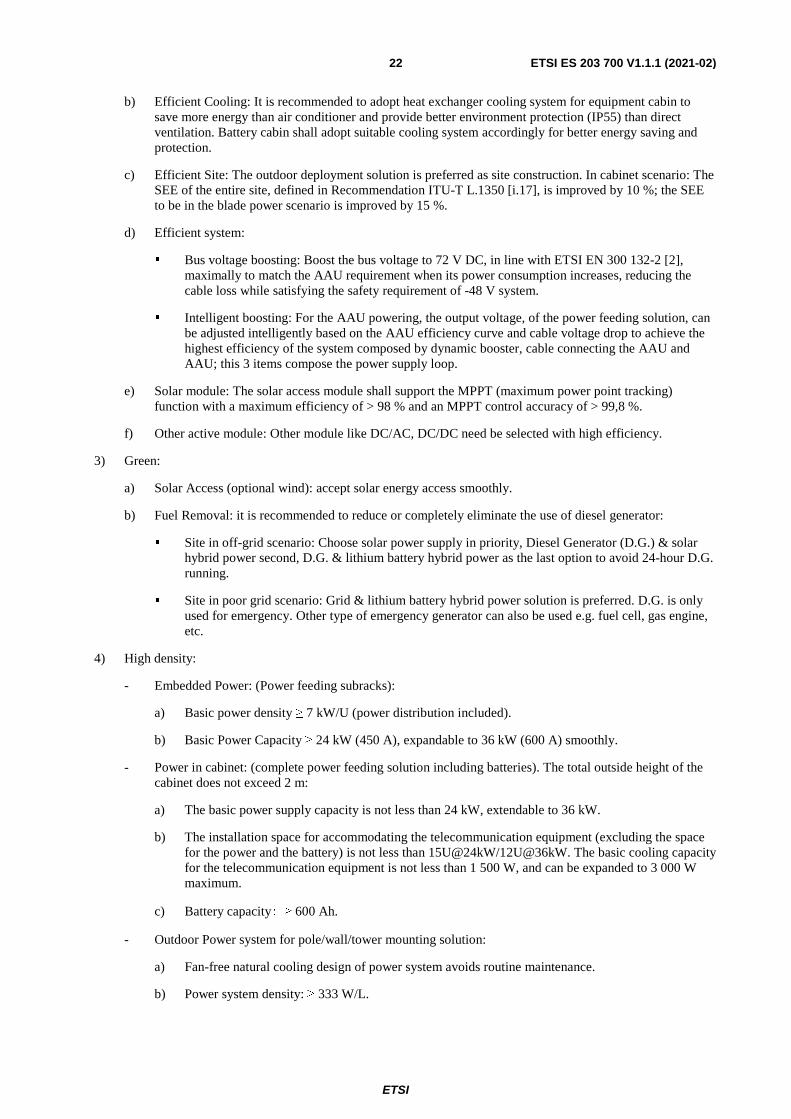
b) Efficient Cooling: It is recommended to adopt heat exchanger cooling system for equipment cabin to save more energy than air conditioner and provide better environment protection (IP55) than direct ventilation. Battery cabin shall adopt suitable cooling system accordingly for better energy saving and protection.
c) Efficient Site: The outdoor deployment solution is preferred as site construction. In cabinet scenario: The SEE of the entire site, defined in Recommendation ITU-T L.1350 [i.17], is improved by 10 %; the SEE to be in the blade power scenario is improved by 15 %.
d) Efficient system:
Bus voltage boosting: Boost the bus voltage to 72 V DC, in line with ETSI EN 300 132-2 [2], maximally to match the AAU requirement when its power consumption increases, reducing the cable loss while satisfying the safety requirement of -48 V system.
Intelligent boosting: For the AAU powering, the output voltage, of the power feeding solution, can be adjusted intelligently based on the AAU efficiency curve and cable voltage drop to achieve the highest efficiency of the system composed by dynamic booster, cable connecting the AAU and AAU; this 3 items compose the power supply loop.
e) Solar module: The solar access module shall support the MPPT (maximum power point tracking) function with a maximum efficiency of > 98 % and an MPPT control accuracy of > 99,8 %.
f) Other active module: Other module like DC/AC, DC/DC need be selected with high efficiency.
3) Green:
a) Solar Access (optional wind): accept solar energy access smoothly.
b) Fuel Removal: it is recommended to reduce or completely eliminate the use of diesel generator:
Site in off-grid scenario: Choose solar power supply in priority, Diesel Generator (D.G.) & solar hybrid power second, D.G. & lithium battery hybrid power as the last option to avoid 24-hour D.G. running.
Site in poor grid scenario: Grid & lithium battery hybrid power solution is preferred. D.G. is only used for emergency. Other type of emergency generator can also be used e.g. fuel cell, gas engine, etc.
4) High density:
- Embedded Power: (Power feeding subracks):
a) Basic power density ≥ 7 kW/U (power distribution included).
b) Basic Power Capacity ≥ 24 kW (450 A), expandable to 36 kW (600 A) smoothly.
- Power in cabinet: (complete power feeding solution including batteries). The total outside height of the cabinet does not exceed 2 m:
a) The basic power supply capacity is not less than 24 kW, extendable to 36 kW.
b) The installation space for accommodating the telecommunication equipment (excluding the space for the power and the battery) is not less than 15U@24kW/12U@36kW. The basic cooling capacity for the telecommunication equipment is not less than 1 500 W, and can be expanded to 3 000 W maximum.
c) Battery capacity: ≥ 600 Ah.
- Outdoor Power system for pole/wall/tower mounting solution:
a) Fan-free natural cooling design of power system avoids routine maintenance.
b) Power system density: ≥ 333 W/L.

ETSI
ETSI ES 203 700 V1.1.1 (2021-02) 23
c) When the power system modules system are used in parallel, the output power of the parallel system shall be no less than 90 % of the total power in case of two power modules and 80 % of the total power in case of more than 2 power modules.
5) Intelligent: see clause 5.2.6.
6) Additional Safety requirements:
- Adopting DC remote power supply safety functions such as safe start up, insulation monitor and AC utility monitor to enhance the system safety shall be present:
a) Safe start up: System automatically shall checks the cable route and remote load correctness in a safe voltage mode, then output voltage rises up to 400 V DC to remote load.
b) Insulation monitor for 400 V DC: System automatically shall monitor system insulation impedance, including + to GND and - to GND. The system shall triggering alarm or cutting output when impedance is lower than the defined threshold.
c) AC utility monitor: The system automatically shall detect AC voltage on the system. The system shall triggering alarm or cutting output when impedance is lower than the defined threshold.
5.2.6 Intelligent Features for C-RAN&D-RAN site
5.2.6.1 Intelligent Peak Shaving
Since the existing grid capacity could only satisfies the peak power of 2/3/4G, it needs to be expanded to meet the later peak power when 5G accesses. A grid expansion includes transformer modernization, power line reconstruction, big engineering and long Time To Market (TTM).
The 5G power shall be capable to cooperate with the energy storage system to shave the peak power when 5G accesses for minimizing the grid modernization and accelerating the 5G deployment.
Figure 9 and Figure 10 show peak shaving functionality concept and an example of sizing.
Figure 9: Peak shaving of a radio site functionality
17kW
15kW
12kW

ETSI
ETSI ES 203 700 V1.1.1 (2021-02) 24
Figure 10: Example of peak shaving of a radio site sizing
The capacity of lithium battery for the peak shaving purpose should be designed according to the gap between peak load and grid limit, and also shall consider the load changing model.
The battery capacity should be designed as reported below:
C =(Pmax - Plimit × k1 × k2)× T × 1,25 / 48 V × DOD (1)
Table 3 reports a calculation example.
Table 3: Example of backup capacity dimension
C: Capacity (Battery capacity for new peak) C= (Pmax - Plimit × k1×k2 × T × 1,25 / (48V × DOD)
Pmax Site peak maximum power Plimit Maximum site grid power T Peak duration k1 Power system efficiency; common value: 0,94 k2 Derating coefficient of grid capacity; common value: 0,8 or 1 DOD Battery depth of discharge; common value of lithium battery: 0,85 1,25 Safety coefficient(optional); consider based on the actual requirement
An example of battery capacity configuration for peak power under the following assumptions:
• Existing grid power: 15 kW (enough for 2/3/4G peak power)
• Peak power of 2/3/4G: 12 kW (including battery charging power)
• Peak power of 5G access: 5 kW
• Peak time/day: 2 hours
• Pmax = 12 + 5 = 17 kW
• Plimit = 15 kW
• T = 2 h
• C = (17 000 W - 15 000 W × 0,94 × 0,8) × 2 × 1,25 / (48 × 0,85) = 350 Ah
Working principle of battery for peak shaving:
When the peak that over the grid power appears, the battery will discharge to shave the extra peak that beyond the grid ability. The configured battery capacity, calculated using formula (1), is specific for peak shaving only.
Meanwhile, in order to ensure the reliable power supply and easy site maintenance, a software management platform should be deployed to real-time monitor the site running status for the operation of peak shaving, and provide early maintenance warnings and optimization suggestions.

ETSI
ETSI ES 203 700 V1.1.1 (2021-02) 25
The controller shall be control the AC input to limit the power from AC below Plimit value.
NOTE 1: The dimensioning of battery capacity need to consider both the required backup time for site as well as the needed backup capacity for the peak shaving function.
NOTE 2: There is no strict relationship between the breaker capacity and the peak shaving function. The breaker capacity should match the specification of the power cable and the design of the battery charge and discharge current, i.e. I_charge/discharge ≤ I_MCB ≤ I_wire. The specific selection refers to the breaker specification/manual from different breaker supplier. Where I_charge/discharge is the charge or discharge battery current, I_MCB is the breaker trip current, I_wire is the cable maximum current.
5.2.6.2 Advance Sleep/Hibernation Mode function
Rectifier Sleep Mode is also one way to maximize the power conversion efficiency of the overall DC Power System.
The DC power system controller will automatically put asleep (based on configurable running conditions) one or more rectifiers in order to keep the system efficiency as high as possible.
This function could be useful if the power consumption is very low compare to the total installed Power of the DC Power System but unnecessary if the DC Power System is equipped with the latest High efficiency rectifier modules (≥ 97 %) and properly sized.
5.3 Intelligent Management
5.3.0 General
In order to meet the ultimate business requirements of 5G network, the standard of power reliability, site energy efficiency, O&M efficiency and site safety of the whole network should be much higher. 5G power system should be able to provide more efficient management and maintenance on the basis of more intelligent software platform, so as to be ready for 5G network evolution. As an evolutionary 5G power system, it should be equipped with the following 4 key management ability.
5.3.1 Power availability Management
Power Availability Value (PAV) refers to the site DC power supply reliability, which is the abbreviation of Power Available Value. It is a percentage of site on-line working time (total time except site shutdown time cause by various DC power supply outage) divided by total designed duration time. The calculation format is:
��� =���� �������� ����� ��� ��� ������ � �� ��� ���
�� � �������� ����� ��� ��� ��� (2)
The management of PAV could be helpful for the precise investment to improve the power supply reliability.
5G power should be capable of intelligent evolution to manage PAV comprehensively:
• 5G power should be able to manage the site power availability.
• 5G power should be able to manage the site power availability. All the key PAV relevant specification of the power should be measured on the basis of ensuring reliable power supply.
• 5G power should support PAV foresighted management.
• Besides system analysis to the site history power supply quality, 5G power should also be able to provide foresighted maintenance suggestions for the up-coming potential risks. For example, it should analysis the real power back-up capability of the energy storage system to provide maintenance suggestions in advance during early grid outage together with the consideration with load changing, so as to avoid site interruption and improve power supply reliability.

ETSI
ETSI ES 203 700 V1.1.1 (2021-02) 26
5.3.2 SEE Management
SEE is an indicator of site E2E energy usage efficiency, which is the abbreviation of Site Energy Efficiency. When a particular sum of energy is provided to one site, only some partial energy goes to main devices while the others is consumed by site supporting devices such as lighting, cooling, PSU and power distribution.
Recommendation ITU-T L.1350 [i.17] defines Site energy efficiency (SEE). SSE is the ratio between the total energy consumption of telecommunication equipment and the total energy consumption on site:
SEE =���
���× 100 % (3)
The power consumption of 5G network will increase dramatically. Precise management of site energy usage efficiency will help to reduce network energy bills and maintenance cost:
• 5G power solution should have the ability to manage SEE.
• 5G power should monitor the energy consumption in detail including the total AC input, main device energy consumption, and every site sub-system energy consumption. Then it should provide SEE result on the basis of detail calculation. Through big data AI analysis, the system should identify the high energy consumption and low SEE sites, and also give out the cause analysis. In this case, precise upgrading and investment suggestion could be made to improve the energy efficiency accordingly.
• SEE analysis together with traffic statistics.
• It is not accurate in some cases to judge one site's energy usage efficiency from the power side only. 5G power should considerate energy efficiency together traffic in the future, and pay attention to the energy consumption for every bit traffic. The ultimate target is bit manages watt to reach high efficiency of bit/watt.
5.3.3 Remote Maintenance
• The maintenance of ICT network should develop towards automation and remote management, so as to improve network production capacity.
• The functionality provided will be able to:
- Build comprehensive digital sensing ability.
- The digital sensing ability of power is the basis to achieve remote and automatic maintenance. 5G power solutions should be able of digital sensing ability.
• Automatic O&M replaces manual O&M:
- On the basis of thorough site digitization, traditional manual O&M is substituted by system automatic O&M, which could save a large sum of operation cost.
• Precise site maintenance reduce not necessary site visit:
- On the basis of site situation close monitoring, the system provides remote trouble-shooting and cause analysis of the already happened malfunction and potential risks. The target is to avoid unnecessary site visit and make only one visit to solve all the problems.
5.3.4 intelligent security
Site quantity will increase in the 5G era and more attention should be paid to the security issue of site assets. 5G power should be equipped with anti-theft ability to maximize site security and reduce the loss caused by theft:
• Comprehensive digitization is the basis of intelligent security.
• It is proved that the traditional physical anti-theft design cannot solve the theft issue. On one hand the theft is becoming more and more concealed and professional. On the other hand, there is a lack of effective management measures for self-stealing. The reason for those frequent happened theft issue is the profit chain.

ETSI
ETSI ES 203 700 V1.1.1 (2021-02) 27
• 5G power should build a whole series of digital protection system surrounding the power and site. For example, digital lock of battery that make it useless if left the site location; site access management automatically record abnormal site visits to avoid theft problem.
• Innovative anti-theft features such as smart video, smart lock, smart alarm, and cloud & AI 5G power ensures site productivity security and asset security comprehensively by adopting innovative anti-theft features such as smart video, smart lock, smart alarm, and cloud & AI.
5.3.5 Intelligent Energy Storage System
Along with the power consumption increasing during 5G evolution, the existing energy storage capacity for 2/3/4G is no longer sufficient. However, expanding the battery capacity by the traditional lead-acid battery faces severe challenges:
• Limited space and weight capacity of numerous existing site including rooftop site and greenfield site, which future leads to high rental, expensive construction cost, long time for site acquisition and even no space for evolution.
• Insufficient power supply distance for 5G equipment on tower due to big cable loss.
• Over capacity configuration in short time backup due to lead-acid battery's weak ability to output its capacity in short time.
• Natural short service life, expensive maintenance cost.
• Long charging time.
Lithium battery in line with Recommendation ITU-T L.1221 [i.15], which can solve all the above problems, is essential for 5G evolution. A lithium battery shall contain the following capabilities to match 5G evolution:
• High density of no less than 25Ah/U to realize space in-situ replacement for 5G access.
• Constant voltage output to satisfy the long-distance power supply for 5G equipment on tower.
• No output power derating when in parallel connection to support large power and reduce battery and cabinet investment.
• The lithium battery shall communicate with power system and management system for remote management. The remote O&M including visible battery parameters like voltage, current, temperature, SOC, SOH, and remote test and customized report; The SOC detection deviation shall be less than 5 % while the SOH detection deviation shall be less than 10 %.
• The lithium battery shall be Lithium Iron Phosphate (LFP) and pass the safety tests such as nail test, burning test, water-immersion test and thermal shock test based on the principle of no fire and no explosion.
5.4 Renewable energy solution for 5G base stations Different energy sources such as the Grid, renewable energy, Generator are connected to the input power panels of base stations in this solution. In order to maximize the utilization of renewable energy, the system will be controlled smartly to use the renewable energy firstly and it will choose Grid, or battery storage system or Generator based on the operation cost in different conditions considering cost of Grid and others. The example to show basic structure of the system is as follows in Figure 11.

ETSI
ETSI ES 203 700 V1.1.1 (2021-02) 28
Figure 11: Multiple energy source input system for 5G base station including renewable energy
When the capacity of Grid is not enough due to increasing power of 5G base station, then renewable energy such as PV system, Wind Turbine and Fuel Cells could be very good choice to increase the input power capacity to make sure the whole system can work well continuously.
5.5 Hybrid architecture scenario, with integration of power and optical networks
Power infrastructure is a critical point in 5G networks due to the high-density of «small cells", coupled with the high reliability requirements. So, innovative solutions will have to be developed, to achieve lower cost, higher efficiency and reliability goals.
A solution is the 5G hybrid cabling scenario, integrating power and optical networks as optical is the most common backhauling medium.
Local and remote powering are the two possible scenarios for power distribution. Local power implies a direct connection to the AC grid, feeding the cell in AC via dedicated supply. AC source could be obtained in different ways: AC grid, connecting to public lighting infrastructure, from private building etc. Service reliability requirements will need the introduction of back-up system: supercapacitor, when the need is only to cover micro interruptions and lithium battery to cover longer black out.
While local powering solutions is well suited for current mobile and fixed access networks, cost and efficiency are becoming a main issue when a huge number of distributed units are to be powered, in addition to the cost and time constraints for realizing the AC connection.
Furthermore, the impact on the deployment plan could be negatively impacted by the need to locate the cells in sub-optimal location due to the limited availability of connection points to the electric grid.
Remote powering solves most of these issues as:
• Connection to AC grid is centralized (less numerous), in central office or in external power concentrator.
• Remote feeding using "up to 400 V DC" voltage reduces the cable dimension allowing the use of the same duct both for optical and power connections.
• To support the required service level, redundancy concepts are applicable, introducing power line duplication or power rings.
• Centralized back up represents a more efficient solution with associated cost reduction.

ETSI
ETSI ES 203 700 V1.1.1 (2021-02) 29
Among the different back-hauling or front-hauling possibilities for future 5G networks, the one based on PON (Passive Optical Network) networks is a promising one. It is based on a tree architecture realized using passive optical splitters. The powering structure could efficiently replicate such communications structure.
As shown in Figure 12, a power layer overlays the optical one. The general principle is to reuse at maximum existing infrastructures as already done for the deployment of optical access network. This means that also power component and cables shall be realized in order to fit these infrastructures (e.g. a power cable should be installable inside a microduct for fiber delivery) and hybrid copper-fiber cables have to be taken in consideration.
Basic concepts are:
• Introduction of a power splitter where an optical splitter is present.
• Usage of "up to 400 V DC" technology in the primary distribution segment.
• Usage of Safety Extra Low Voltage (SELV) DC voltage to feed the equipment.
Figure 12 contains the hybrid architecture and Figure 13 contains a schematics architecture.
Figure 12: "Power-optical" hybrid access architecture
Due to the density of small cells, an architecture based on direct connections from Power Nodes to the Remote Radio Unit could not be efficient. A solution is the introduction of an intermediate distribution point splitting the power network in two different segments.
The first one, at higher DC voltage, named Primary Distribution, delivers the power from a Power Node to a distribution point. The second, at SELV levels, will feed, from the distribution point, the radio equipment RRUs. This will avoid co-location of Power Node and Optical Unit, enabling cost-effective powering.
The expected small cell density suggests connecting a maximum of 8 RRU to a distribution point at maximum length of 2 km in the primary distribution and 300 m in the secondary one with a capability of 100 W on the average RRU (or RRH -Remote Radio Head) power requirement and 1 kW on the primary distribution.
Figure 13: Architecture schematics
A - Network architecture: Primary Distribution
Two different architectures are analysed, as detailed in Figure 14 and Figure 15.

ETSI
ETSI ES 203 700 V1.1.1 (2021-02) 30
A simple tree solution where an AC/"up to 400 V DC" converter, named Power Transmitter Unit (PTU), implemented in a Power Node (PN) feeds a Distribution Point (DP) where a Power Splitter (PS) is located, together with an optical one (OS). PN will be in a Central Office or located depending the network demand.
This point to point architecture provides an efficient solution in term of cost, simplifying the cabling aspect, but is not the most reliable solution, as a single fault could affect multiple RRU.
Figure 14: Tree architecture
A second solution, based on ring architecture has higher reliability. Two PTUs are provided feeding the ring, one on the West side, the other on the East one. This architecture allows to feed several distribution points, having a limit only in the cable dimension and in the voltage drop. The PTU's act in a load sharing mode and communicate together in order to maintain aligned their parameters.
Figure 15: Power Ring architecture
B - Network architecture: Secondary Distribution
This segment connects DP to the final equipment RRU (Remote Radio Unit). In order to compensate the drop on cables a voltage up to 60 V DC could be used, staying in the SELV (safety extra-low voltage) range to simplifying the safety aspect. The DP is typically installed in a dedicated box, with possible allocation at a cabinet, pole or underground. It mainly consists in a Power Splitter converting "up to 400 V DC" to SELV levels. Independent converter per RRU can be implemented to avoid influence between outputs in case of fault, increasing service availability as reported in Figure 16.
Redundancy on input line can be obtained both through a 1+1 configuration or a power ring.

ETSI
ETSI ES 203 700 V1.1.1 (2021-02) 31
Figure 16: DP structure
C - Maintenance and control
The characteristics of the power distribution network in terms of field distribution and high density recommends the introduction of management functions to track in real time the network status and carry out the appropriate maintenance activity see ETSI ES 202 336-12 [i.2].
D - Backup element
The back-up solutions are specified in standard series for innovative energy storage selection and tests method overview in ETSI TS 103 553-1 [i.11] or Recommendation ITU-T L.1220 [i.14] case of batteries in Recommendation ITU-T L.1221 [i.15] and case of super capacitors in Recommendation ITU-T L.1222 [i.16].
E - Cables considerations
To implement the scenario described in the present clause, it is not strictly necessary to use new kind of cables but it is possible to identify some optimal solutions to reduce the overall cost of deployment.
EXAMPLE: In the primary distribution segment it would be opportune to opt for power cables that can be installed in existing telecommunications infrastructures (e.g. microducts installed to host optical cables).
The secondary feeding segment requires the adoption of a new generation of hybrid or composite cables, being able to carry both signals (through fiber optics) and electric power to supply the radio equipment. These cables are typically characterized by the presence of at least two or more electrical conductors and one or more optical fibers. As specified in ETSI EN 301 605 [i.3] standard, some conductors could be required for earthing purposes.
It can be assumed that the leading transmission architecture will be GPON, needing only one fiber, nevertheless one extra fiber would be useful as a backup, for architectures using 2 fibers for upstream and downstream direction or for redundant paths. The outer dimensions of the hybrid cables should be small enough to be easily inserted, when required, into PVC microducts (about 10 mm diameter) and the outer jacket of the cable shall be made of fire retardant material and resist the atmospheric agents (rain, UV rays, ice, etc.). If the installation is mechanically stressful, the composite or hybrid cable shall integrate a tensile high strength core, to be safely pulled or to resist external mechanical agents.
The sizes of the electrical conductors are obviously depending on the applications, that is on the electric load and the distance to be covered. It can be envisaged that the distance should be in the order of 100 ÷ 1 000 m and the electric power around 100 ÷ 1 000 W, in relation to the appropriate distribution segment.
For electrical safety aspects related the adoption of "up to 400 V DC" voltages, the relevant safety standards apply and further details can be found in ETSI EN 300 132-3-1 [3] and Recommendation ITU-T L.1200 [i.13].

ETSI
ETSI ES 203 700 V1.1.1 (2021-02) 32
6 Energy Efficiency
6.1 Power equipment energy efficiency For the purpose of more efficient, greener and more saving, the efficiency of rectifier for 5G power is recommended to be more than 97 % from 20 to 80 %, and more than 94 % from 10 to 20 % load rate. Load rate with less than 10 % indicates over-configured rectifier. Thus considering less than 10 % load rate is meaningless
6.2 NE static and dynamic power requirement management and impact on powering
Low power mode management: The NE shall have a power level dependant to Telecom service load, in order to be able to put the power supply unnecessary modules in deep low power mode. At no service load, the NE shall consume less than 10 % of its maximum consumption.
The wake-up shall be sufficiently fast to allow operation without back-up considering the hold-up time of NE as defined at their interface A ETSI EN 300 132-2 [2] or A1 ETSI EN 300 132-1 [1] or A3 ETSI EN 300 132-3-1 [3].
Global efficiency target:
Full standby mode: there shall be at network level a control of nodes activity, to be able to shut down unused nodes and wake-up them when required.
Partial low power mode:
The network should be able to dynamically drive nodes functionalities to their lowest energy consumption modes compatible with the required level of service.
7 Dependability, reliability and maintenance The availability and reliability of the powering shall be defined in coherence with the service and end to end network requirement with some margin and allow its evolution.
ETSI TS 122 261 [i.4], Table 7.2.2-1 defines the main availability requirements of 5G services. The actual availability of 5G networks will depend on the service categories they are planned to serve.
Other major parameters to define the powering solution and sizing are:
• The AC grid availability, quality and time to restore from a grid failure.
• The compatibility of a new powering with existing NE on the same site.
• The power load evolution within the site and the NE configuration evolution (Number and type of equipment, setting of the equipment, etc.).
• Coverage and Traffic.
The availability and scalability requirement guide setting the requirements of power system architecture and sizing parameters such as:
• Power supply and distribution redundancy, when considering a remote powering, it can be:
- 1 line for 1 equipment.
- n lines for 1 equipment.
- 1 line for n equipment.
- 1 powering ring which allows one fault in the ring through redundant paths.

ETSI
ETSI ES 203 700 V1.1.1 (2021-02) 33
• Energy storage autonomy for local powering or at remote powering cluster site level and possibly also on remote site.
• Choice of power generators (grid, renewable energy, hybrid systems, etc.).
Safety
Safety of 5G installation shall follow relevant safety standard in force covering installation requirement and national rule.
8 Environmental impact Environmental impact assessment of 5G powering solution shall be conducted in line with the methodologies described in ETSI ES 203 199 [4] or Recommendation ITU-T L.1410 [5].

ETSI
ETSI ES 203 700 V1.1.1 (2021-02) 34
Annex A (informative): Which power and where for 5G cells This annex is providing information for understanding which power requirement is required and where:
• Higher frequency would be used first in the range 700 MHz to 30 GHz (maybe later up to 300 GHz), offering higher bandwidth than 4G, up to 20 Gbps. At high frequency and bandwidth it is interesting to work with smaller cells than macro-cells used in previous 2G to 4G. As for 2G to 4G, low band up to 2 GHz are for coverage Layer, but medium/high band (1 GHz to 6 GHz) increases capacity and very high Bands (above 6 GHz) would be used for High traffic areas. At very high frequency the issue of efficient and low cost radio frequency electronic is still a critical point, see Figure A.1.
Source: https://www.cablefree.net/wirelesstechnology/4glte/5g-frequency-bands-lte/ [i.21].
Figure A.1: 5G frequency subdivision
This leads to the following hypothesis for cell coverage and density:
• 0,1 to 0,3 km range Small Cells rather than 1 km range Macro Cells. that means a density of cell per km² multiplied per 10 to 100.
• The small cell will be installed far from existing grid or other power indirect connection such as bus stop or street light (these indirect connection small cell are less convenient as they are switched off during the day, so a battery would be required in the 5G cell).
The small cell average power consumption range is in the range of tens of W to hundreds of W.
Another issue is the need and specification of energy back-up for covering grid interruption or for optimizing remote power feeding by shaving the power peaks.
If only short interruption are to be considered, it could be interesting to use high power supercapacitor or Lithium battery in ETSI TS 103 553-1 [i.11] or Recommendations ITU-T L.1220 [i.14], L.1221 [i.15] and L.1222 [i.16].

ETSI
ETSI ES 203 700 V1.1.1 (2021-02) 35
Annex B (informative): Method of optimization of equipment, power and energy In order to reduce number of cells and their powering issues and avoid explosion of power consumption and cost, the following optimization method reported in Figure B.1, is proposed.
Figure B.1: Optimization methodology
The method is circular and iterative. It is linked to circular economy targets. It is based on the following three improvement steps:
• Function sufficiency is a way to optimize service and minimize functional requirement.
• Energy and material Efficiency is a way to optimize equipment in terms of impact on environment, thermal management and electric bill for operators while matching the required service.
• Renewable Energy is generally more enabled by the previous efforts as a lower power will reduce the size and cost of generator and energy storage.
The method is described by a circle because the starting step is not always the same.
The method is iterative, because each improvement step can impact on the other e.g. by enabling solutions that were not possible before.
In some cases (bad grids, difficult remote powering, etc.), standalone energy will be chosen as first entrance step. It is often wished to avoid use of fuel generators and all their issues (higher operational cost, fuel risks, noise, pollution, etc.) depending on the generator type. So REN is chosen and it absolutely needs to optimize iteratively power and energy next steps of the circle.
The iterative approach can be applied as follows:
• Renewable energy is sized.
• If it is not enough e.g. due to available site area or budget target, sufficiency is checked. A further functional review is done to reduce functions to what is considered sufficient (e.g. it is really necessary to have the maximum bandwidth 24 hour per day and every day?).
• Then it is checked if it opens new efficiency gain?
• Then REN is resized.
• Then other turns are done until the solution status is considered acceptable.
Sufficiency*
Efficiency Renewable
Energy

ETSI
ETSI ES 203 700 V1.1.1 (2021-02) 36
This can be done site by site or at network level as the network optimal solution can be different from each site optimal solution.

ETSI
ETSI ES 203 700 V1.1.1 (2021-02) 37
Annex C (informative): Example of powering requirement definition on site and remote powering area This annex considers the powering solution not the energy consumption of different configuration of network, which is a completely different question especially when power is service load dependant, which is required to save energy.
Assuming different cells scale with the following power consumption as an example:
• Macro cell site 2 to 8 kW for NE equipment, power station and cooling.
• Micro cell site up to 500 W.
• Pico cell up to 100 W.
• Femto cell up to 20 W.
Different network configuration and the possible powering solutions are reported below.
Case study of 1 km² homogeneous cell network
There will be very few small and very small cells e.g.:
The global power is at 80 % for 1 to 3 macro cell sites and so for example less than about 15 kW/km², the micro cell accounting for 3 kW.
Each macro cell site would be connected to AC grid with contract from 6 to 12 kVA, and a remote power of 3 kW can be fed to the few small cells from one macro cell site or existing central offices of the same area to accommodate to existing duct without major changes.
Case study of 1 km² cell Hetnet
The power could be used for 1 macro cells complemented by 10 to 100 small cells. For example, 1 macro cell of 5 kW + 5 micro cells of 0,5 kW + 20 pico cells of 50 W + 50 femto cells of 10 W.
The total power of all these 76 cells is then 9 kW/km².
It can be in that study case very interesting to power the small cells without AC grid connection as the fees will be very expensive, the amount it is about 4 kW by remote powering, from a cluster site, and the remaining few bigger site on AC grid.
In addition, it is highly probable that there will be much a much less than 76 lines as many sites would be gathered on the same main branches with ramifications to distribute small power to pico and femto cells connected to the same branch (or bus) in the area of 1 km².
The macro or micro cell site would be connected to AC grid with some contract from 3 to 12 kVA, while the remote power of 9 kW can be fed to the few small cells from the macro cell site or from a cluster powering site or from existing central offices of the same area to accommodate to existing duct without major changes.

ETSI
ETSI ES 203 700 V1.1.1 (2021-02) 38
Annex D (informative): Example of required output voltage variation under correlation models between different load and different cable length This annex considers the required output voltage variation under correlation models between different load and different cable length, which is taken as reference when evaluate whether existing cable deployment acceptable for 5G AAU working under general voltage range and temperature condition 35 ℃.
Premise:
1) Consider the conductivity of copper cable being 57 m / Ω × mm ^ 2, R = 2 × L/S × σ, with Resistivity 0,0175 Ω / m × mm ^ 2 under temperature coefficient 0,00393 Ω / °C.
2) The input voltage at the load end from 36 V to 57 V is considered as general working range of the 5G AAU.
Figure D.1 reports the result considering a 6 mm2 cooper cable.
Figure D.2 reports the result considering a 8,2 mm2 cooper cable.
Figure D.3 reports the result considering a 10 mm2 cooper cable.
Figure D.1: Required output voltage variation under correlation between load and cable length (6 mm2 cooper cable)
Load(W)
1700 48 48 57 57 57 57 57 57 57 57 57 72 72 72 72 72 72 72 72 72 72 72 72
1600 48 48 57 57 57 57 57 57 57 57 57 57 72 72 72 72 72 72 72 72 72 72 72
1500 48 48 48 57 57 57 57 57 57 57 57 57 57 72 72 72 72 72 72 72 72 72 72
1400 48 48 48 57 57 57 57 57 57 57 57 57 57 57 72 72 72 72 72 72 72 72 72
1300 48 48 48 48 57 57 57 57 57 57 57 57 57 57 57 57 72 72 72 72 72 72 72
1200 48 48 48 48 57 57 57 57 57 57 57 57 57 57 57 57 57 72 72 72 72 72 72
1100 48 48 48 48 48 57 57 57 57 57 57 57 57 57 57 57 57 57 57 72 72 72 72
1000 48 48 48 48 48 48 57 57 57 57 57 57 57 57 57 57 57 57 57 57 57 72 72
900 48 48 48 48 48 48 48 57 57 57 57 57 57 57 57 57 57 57 57 57 57 57 57
800 48 48 48 48 48 48 48 48 57 57 57 57 57 57 57 57 57 57 57 57 57 57 57
700 48 48 48 48 48 48 48 48 48 48 57 57 57 57 57 57 57 57 57 57 57 57 57
600 48 48 48 48 48 48 48 48 48 48 48 48 57 57 57 57 57 57 57 57 57 57 57
500 48 48 48 48 48 48 48 48 48 48 48 48 48 48 48 48 57 57 57 57 57 57 57
400 48 48 48 48 48 48 48 48 48 48 48 48 48 48 48 48 48 48 48 48 57 57 57
300 48 48 48 48 48 48 48 48 48 48 48 48 48 48 48 48 48 48 48 48 48 48 48
200 48 48 48 48 48 48 48 48 48 48 48 48 48 48 48 48 48 48 48 48 48 48 48
100 48 48 48 48 48 48 48 48 48 48 48 48 48 48 48 48 48 48 48 48 48 48 48
20 25 30 35 40 45 50 55 60 65 70 75 80 85 90 95 100 105 110 115 120 125 130
Cable Length (m)

ETSI
ETSI ES 203 700 V1.1.1 (2021-02) 39
Figure D.2: Required output voltage variation under correlation between load and cable length (8,2 mm2 coper cable)
Figure D.3: Required output voltage variation under correlation between load and cable length (10 mm2 coper cable)
Load(W)
1700 48 48 48 48 57 57 57 57 57 57 57 57 57 57 57 57 72 72 72 72 72 72 72
1600 48 48 48 48 57 57 57 57 57 57 57 57 57 57 57 57 57 72 72 72 72 72 72
1500 48 48 48 48 48 57 57 57 57 57 57 57 57 57 57 57 57 57 57 72 72 72 72
1400 48 48 48 48 48 48 57 57 57 57 57 57 57 57 57 57 57 57 57 57 72 72 72
1300 48 48 48 48 48 48 57 57 57 57 57 57 57 57 57 57 57 57 57 57 57 57 72
1200 48 48 48 48 48 48 48 57 57 57 57 57 57 57 57 57 57 57 57 57 57 57 57
1100 48 48 48 48 48 48 48 48 57 57 57 57 57 57 57 57 57 57 57 57 57 57 57
1000 48 48 48 48 48 48 48 48 48 57 57 57 57 57 57 57 57 57 57 57 57 57 57
900 48 48 48 48 48 48 48 48 48 48 48 57 57 57 57 57 57 57 57 57 57 57 57
800 48 48 48 48 48 48 48 48 48 48 48 48 57 57 57 57 57 57 57 57 57 57 57
700 48 48 48 48 48 48 48 48 48 48 48 48 48 48 48 57 57 57 57 57 57 57 57
600 48 48 48 48 48 48 48 48 48 48 48 48 48 48 48 48 48 48 57 57 57 57 57
500 48 48 48 48 48 48 48 48 48 48 48 48 48 48 48 48 48 48 48 48 48 48 57
400 48 48 48 48 48 48 48 48 48 48 48 48 48 48 48 48 48 48 48 48 48 48 48
300 48 48 48 48 48 48 48 48 48 48 48 48 48 48 48 48 48 48 48 48 48 48 48
200 48 48 48 48 48 48 48 48 48 48 48 48 48 48 48 48 48 48 48 48 48 48 48
100 48 48 48 48 48 48 48 48 48 48 48 48 48 48 48 48 48 48 48 48 48 48 48
20 25 30 35 40 45 50 55 60 65 70 75 80 85 90 95 100 105 110 115 120 125 130
Cable Length (m)
Load(W)
1700 48 48 48 48 48 48 57 57 57 57 57 57 57 57 57 57 57 57 57 57 72 72 72
1600 48 48 48 48 48 48 57 57 57 57 57 57 57 57 57 57 57 57 57 57 57 57 72
1500 48 48 48 48 48 48 48 57 57 57 57 57 57 57 57 57 57 57 57 57 57 57 57
1400 48 48 48 48 48 48 48 48 57 57 57 57 57 57 57 57 57 57 57 57 57 57 57
1300 48 48 48 48 48 48 48 48 57 57 57 57 57 57 57 57 57 57 57 57 57 57 57
1200 48 48 48 48 48 48 48 48 48 57 57 57 57 57 57 57 57 57 57 57 57 57 57
1100 48 48 48 48 48 48 48 48 48 48 48 57 57 57 57 57 57 57 57 57 57 57 57
1000 48 48 48 48 48 48 48 48 48 48 48 48 57 57 57 57 57 57 57 57 57 57 57
900 48 48 48 48 48 48 48 48 48 48 48 48 48 48 57 57 57 57 57 57 57 57 57
800 48 48 48 48 48 48 48 48 48 48 48 48 48 48 48 48 57 57 57 57 57 57 57
700 48 48 48 48 48 48 48 48 48 48 48 48 48 48 48 48 48 48 48 57 57 57 57
600 48 48 48 48 48 48 48 48 48 48 48 48 48 48 48 48 48 48 48 48 48 48 57
500 48 48 48 48 48 48 48 48 48 48 48 48 48 48 48 48 48 48 48 48 48 48 48
400 48 48 48 48 48 48 48 48 48 48 48 48 48 48 48 48 48 48 48 48 48 48 48
300 48 48 48 48 48 48 48 48 48 48 48 48 48 48 48 48 48 48 48 48 48 48 48
200 48 48 48 48 48 48 48 48 48 48 48 48 48 48 48 48 48 48 48 48 48 48 48
100 48 48 48 48 48 48 48 48 48 48 48 48 48 48 48 48 48 48 48 48 48 48 48
20 25 30 35 40 45 50 55 60 65 70 75 80 85 90 95 100 105 110 115 120 125 130
Cable Length (m)

ETSI
ETSI ES 203 700 V1.1.1 (2021-02) 40
Annex E (informative): Digital Reconfigurable Battery solution for 5G base stations It is expected that there will be a plenty of battery to be adopted as various back-up power systems and renewable energy storage systems in 5G network.
A digital reconfigurable battery system is illustrated in Figure E.1, where cell level topology can be modified to accommodate cell characteristics and load efficiently. This ability is achieved by deploying power switches around battery cells and adjusting cell connectivity in a real time fashion. A basic requirement of a BCS is that it should be capable of bypassing any cell as well as adjusting the configuration of cells according to real time operational conditions, such as cell status and load profile, while keeping a balanced cell states across the entire battery pack.
Figure E.1: Architecture of digital reconfigurable battery system
Figure E.2 illustrates the system diagram of a typical digital battery system, where a switching circuit enables reconfiguration on cell level topology within 10 milliseconds. As a result, power management and control in this system can be conducted dynamically on cell level, array level, pack level, and battery network level by means of network and information. Higher energy efficiency, better safety and reliability can be achieved through proper management on cells and reconfiguration on cell topologies. Meanwhile, the system is capable of isolating arbitrary faulty cells as well as achieving cell-to-cell balanced condition, meaning that the lifespan of the system will become much longer than that of traditional battery pack with fixed topology and the same number of single cells under the identical load and operational conditions. Furthermore, the distributed nature of such a system also paves the way for high utilization of repurposed EV battery.

ETSI
ETSI ES 203 700 V1.1.1 (2021-02) 41
Figure E.2: System diagram of digital reconfigurable battery systems

ETSI
ETSI ES 203 700 V1.1.1 (2021-02) 42
Annex F (informative): Bibliography
• C. Bianco et al.: "Powering future network architectures" - Intelec 2018.
• D. Marquet et al.: "Telecom Operator's to accelerate the migration towards 400 Volt Direct Current" - Intelec 2017.
• ETSI and ITU-T joint EE 5G Workshop: "5G smart sustainable powering", Didier Marquet, Orange 24 November 2017.
• ETSI and ITU-T joint EE 5G Workshop: "Achieving energy efficiency and smart energy for 5G" 5G, Shuguang Qi, CATR China, 24 November 2017.
• "Study on Power Feeding System for 5G Network", Shuguang Qi, Xin Gong, Shang Li, Intelec 2018.

ETSI
ETSI ES 203 700 V1.1.1 (2021-02) 43
History
Document history
V1.1.0 May 2020 Membership Approval Procedure MV 20200720: 2020-05-21 to 2020-07-20
V1.1.1 December 2020 Membership Approval Procedure MV 20210208: 2020-12-10 to 2021-02-08
V1.1.1 February 2021 Publication