es 200 677 - v01.02.01 - public switched telephone … telecommunications standards institute es 200...
TRANSCRIPT

European Telecommunications Standards Institute
ES 200 677 V1.2.1 (1998-03)ETSI Standard
Public Switched Telephone Network (PSTN);Requirements for handset telephony
ES 200 677 V1.2.1 (1998-03)2
ReferenceRES/ATA-004124 (69o00iop.PDF)
KeywordsAcoustic, analogue, PSTN, telephony, terminal
ETSI Secretariat
Postal addressF-06921 Sophia Antipolis Cedex - FRANCE
Office address650 Route des Lucioles - Sophia Antipolis
Valbonne - FRANCETel.: +33 4 92 94 42 00 Fax: +33 4 93 65 47 16
Siret N° 348 623 562 00017 - NAF 742 CAssociation à but non lucratif enregistrée à laSous-Préfecture de Grasse (06) N° 7803/88
[email protected]://www.etsi.fr
http://www.etsi.org
Copyright Notification
No part may be reproduced except as authorized by written permission.The copyright and the foregoing restriction extend to reproduction in all media.
© European Telecommunications Standards Institute 1998.All rights reserved.
ES 200 677 V1.2.1 (1998-03)3
Contents
Intellectual Property Rights ............................................................................................................................... 5
Foreword ............................................................................................................................................................ 5
Introduction........................................................................................................................................................ 5
1 Scope........................................................................................................................................................ 6
2 References ............................................................................................................................................... 62.1 Normative references......................................................................................................................................... 62.2 Informative references ....................................................................................................................................... 7
3 Definitions and abbreviations.................................................................................................................. 73.1 Definitions ......................................................................................................................................................... 73.2 Abbreviations..................................................................................................................................................... 8
4 Speech transmission aspects.................................................................................................................... 84.1 General............................................................................................................................................................... 84.1.1 Polarity independence .................................................................................................................................. 84.1.2 Feed resistance ............................................................................................................................................. 94.1.3 Power supply................................................................................................................................................ 94.1.4 Volume control............................................................................................................................................. 94.2 Speech performance characteristics ................................................................................................................. 104.2.1 Sensitivity - frequency response................................................................................................................. 104.2.1.1 Sending................................................................................................................................................. 104.2.1.2 Receiving.............................................................................................................................................. 104.2.2 Sending and Receiving Loudness Ratings.................................................................................................. 124.2.2.1 Sending Loudness Rating ..................................................................................................................... 124.2.2.2 Receiving Loudness Rating .................................................................................................................. 134.2.2.3 Volume control ..................................................................................................................................... 134.2.3 Sidetone...................................................................................................................................................... 144.2.4 Distortion ................................................................................................................................................... 144.2.4.1 Sending distortion................................................................................................................................. 144.2.4.2 Receiving distortion.............................................................................................................................. 154.2.4.3 Sidetone distortion................................................................................................................................ 154.2.4.4 Sending power-handling capability ...................................................................................................... 154.2.4.5 Receiving power-handling capability ................................................................................................... 154.2.5 Linearity (variation of gain with input level).............................................................................................. 154.2.5.1 Sending................................................................................................................................................. 154.2.5.2 Receiving.............................................................................................................................................. 154.2.6 Noise .......................................................................................................................................................... 164.2.6.1 Sending noise........................................................................................................................................ 164.2.6.2 Receiving noise..................................................................................................................................... 164.2.7 Echo return loss.......................................................................................................................................... 164.2.8 Instability ................................................................................................................................................... 16
5 Physical modules ................................................................................................................................... 165.1 Handset ............................................................................................................................................................ 16
Annex A (normative): Maximum acoustically stimulated output .................................................. 17
A.1 Maximum acoustically stimulated output.............................................................................................. 17
Annex B (informative): Acoustic shock ............................................................................................... 18
B.1 General................................................................................................................................................... 18B.1.1 Continuous signal............................................................................................................................................. 18B.1.2 Peak signal ....................................................................................................................................................... 18

ES 200 677 V1.2.1 (1998-03)4
Annex C (informative): Immunity to out-of-band signalling ............................................................ 19
C.1 Sending .................................................................................................................................................. 19
C.2 Receiving ............................................................................................................................................... 19
Annex D (informative): Additional requirement for d.c. characteristics ......................................... 20
D.1 Introduction............................................................................................................................................ 20
D.2 Requirement........................................................................................................................................... 20
History.............................................................................................................................................................. 21
ES 200 677 V1.2.1 (1998-03)5
Intellectual Property RightsIPRs essential or potentially essential to the present document may have been declared to ETSI. The informationpertaining to these essential IPRs, if any, is publicly available for ETSI members and non-members, and can be foundin ETR 314: "Intellectual Property Rights (IPRs); Essential, or potentially Essential, IPRs notified to ETSI in respect ofETSI standards", which is available free of charge from the ETSI Secretariat. Latest updates are available on the ETSIWeb server (http://www.etsi.fr/ipr).
Pursuant to the ETSI Interim IPR Policy, no investigation, including IPR searches, has been carried out by ETSI. Noguarantee can be given as to the existence of other IPRs not referenced in ETR 314 (or the updates onhttp://www.etsi.fr/ipr) which are, or may be, or may become, essential to the present document.
ForewordThis ETSI Standard (ES) has been produced by ETSI Project Analogue Terminals and Access (ATA).
IntroductionThe present document is an updated version of I-ETS 300 677 [3] and describes the requirements for handset telephonyterminals intended for connection to the Public Switched Telephone Network (PSTN) as described in the Scope. Testmethods to verify conformance to the present document are contained in an associated standard (I-ETS 300 480 [2]).
It is recognized that for historical reasons, feed resistances for test purposes, send and receive loudness and for sidetonemay have values particular to each country's network. These requirements are specified in a common text which, wherenecessary, includes parameters to which each country may assign its own national values, which are set out inaccompanying tables.
ETSI has derived values for send and receive loudness ratings and for sidetone performance which are currentlybelieved to be reasonable targets for handset telephony requirements in the future, when inter-exchange connections aremostly digital and the only source of loss is in the local analogue access.
The values were derived from the long term objectives for Sending Loudness Rating (SLR) and Receiving LoudnessRating (RLR) as described in ITU-T Recommendation G.121, taking into account R and T pads assumed to be 7 dB and0 dB respectively, and allowing for an average loss of 4 dB in each local connection due to either the local line or toadditional attenuation inserted in the local exchange in the case of connections with short lines.
These have been implemented in TBR 038 [4], a standard for handset telephony terminal equipment which is intendedfor pan-European approval, and have been incorporated in the present document as "TBR 038 [4] values".
The values given in the tables of national values have been derived by transposing existing national regulatoryrequirements into values that would be obtained by the new harmonized test methods contained in I-ETS 300 480 [2].
National Administrations were invited to endorse these new national values.
At the Public Enquiry, this introduction stated that:
"If national values are not provided, the national values presently marked "Not Available" will be replaced by theproposed harmonized values in the published I-ETS".
Where national values were not provided following public enquiry, the TBR 038 [4] values have been inserted andmarked with an *.

ES 200 677 V1.2.1 (1998-03)6
1 ScopeThe present document specifies those electro-acoustical characteristics that a handset telephony terminal should fulfil toensure the minimum speech quality when communicating across the European Public Switched Telephone Networks(PSTNs).
The objective of the present document is to ensure interworking between Terminal Equipment (TE) via the publicnetwork.
The present document applies in conjunction with the general requirements for PSTN access contained inETS 300 001 [1]. The requirements of the present document are additional to those for connection to the two-wireinterface of the PSTN specified in ETS 300 001 [1].
The requirements of the present document provide real-time (live) two-way speech of a quality consistent with theITU-T (CCITT) P-series Recommendations.
The testing specification for analogue handset telephony is specified in I-ETS 300 480 [2].
The present document is applicable both to handset telephony terminals and the handset telephony function of amulti-function terminal.
The following functions are outside the scope of the present document:
- handsfree or loudspeaking function;
- cordless telephony;
- telephony for people with audio-related impairments (e.g. telephones with additional receive amplification as anaid for the hard of hearing);
- telephony terminals designed for use in hostile environments;
- key systems or Private Automatic Branch eXchange (PABX) system dependent terminals;
- telephones using non-linear or time variant signal processing techniques.
2 ReferencesReferences may be made to:
a) specific versions of publications (identified by date of publication, edition number, version number, etc.), inwhich case, subsequent revisions to the referenced document do not apply; or
b) all versions up to and including the identified version (identified by "up to and including" before the versionidentity); or
c) all versions subsequent to and including the identified version (identified by "onwards" following the versionidentity); or
d) publications without mention of a specific version, in which case the latest version applies.
A non-specific reference to an ETS shall also be taken to refer to later versions published as an EN with the samenumber.
2.1 Normative references[1] ETS 300 001: "Attachments to the Public Switched Telephone Network (PSTN); General
Technical requirements for equipment connected to an analogue subscriber interface in the PSTN".
[2] I-ETS 300 480: "Terminal Equipment (TE); Attachments to the Public Switched TelephoneNetwork (PSTN); Testing specification for analogue handset telephony".

ES 200 677 V1.2.1 (1998-03)7
2.2 Informative referencesFor the purposes of the present document, the following references used within the text have been provided forinformation:
[3] I-ETS 300 677 (1996): "Public Switched Telephone Network (PSTN); Requirements for handsettelephony".
[4] TBR 038: "Public Switched Telephone Network (PSTN); Attachment requirements for a terminalincorporating an analogue handset function capable of supporting the justified case service whenconnected to the analogue interface of the PSTN in Europe".
[5] ITU-T Recommendation P.10 (1993): "Vocabulary of terms on telephone transmission quality andtelephone sets".
[6] CCITT Recommendation P.35 (1988): "Handset Telephones".
[7] 73/23/EEC: "Council Directive of 19 February 1973 on the harmonization of the laws of theMember States relating to electrical equipment designed for use within certain voltage limits".
[8] ITU-T Recommendation P.57 (1993): "Artificial ears".
3 Definitions and abbreviations
3.1 DefinitionsFor the purposes of the present document, the following definitions apply:
acoustic shock: Any temporary or permanent disturbance of the functioning of the ear, or of the nervous system, whichmay be caused to the user of a telephone earphone by a sudden sharp rise in the acoustic pressure produced by it (seeITU-T Recommendation P.10 [5]).
artificial ear: A device for the calibration of earphones incorporating an acoustic coupler and a calibrated microphonefor the measurement of sound pressure and having an overall acoustic impedance similar to that of the average humanear over a given frequency band (see ITU-T Recommendation P.10 [5]).
handset: A combination of telephone microphone and receiver in a form convenient for holding simultaneously tomouth and ear, which, when in use, retains the microphone in a position fixed in relation to the receiver.
handsfree function: A function whereby telephony transmission and reception is facilitated by the use of microphone(s)and loudspeaker(s) placed at a distance from the user. No handset is required to be used and normally the handset is notactive.
loudness rating: A measure, expressed in decibels, for characterizing the loudness performance of complete telephoneconnections or of parts thereof such as sending system, line, receiving system (see ITU-T Recommendation P.10 [5]).An increase in a loudness rating corresponds to a decreasing subjective impression of loudness and vice versa.
loudspeaking function: A function whereby the incoming signal is presented to the user(s) from loudspeaker(s) and thehandset is used simultaneously for sending in its normal speaking position.
Mouth Reference Point (MRP): A point 25 mm in front of and on the axis of the lip position of a typical human mouth(or artificial mouth) (see ITU-T Recommendation P.10 [5]).
Not Mandatory (NM): Indicates that the requirement in the common text with which the table is associated is notsubject to mandatory compliance testing in that country, and that no parameter value has been assigned to it.
Sidetone Masking Rating (STMR): A rating whereby the perceived loudness of the sidetone attributable to atelephone is calculated as the loudness of the speech via the electrical path masked by the speech via the natural paths(bone conduction and leakage at the ear).

ES 200 677 V1.2.1 (1998-03)8
3.2 AbbreviationsFor the purposes of the present document, the following abbreviations apply:
d.c. direct currente.m.f. electromotive forceMRP Mouth Reference PointNM Not MandatoryPABX Private Automatic Branch eXchangePSTN Public Switched Telephone NetworkRLR Receiving Loudness RatingSLR Sending Loudness RatingSPL Sound Pressure LevelSTMR Sidetone Masking RatingTE Terminal Equipment
4 Speech transmission aspects
4.1 General
4.1.1 Polarity independence
The Terminal Equipment (TE) shall conform to the requirements of the present document for both polarities of linefeeding voltage.
Compliance shall be checked by reversal of the d.c. voltage applied to the terminal under test between changes of testconfiguration.

ES 200 677 V1.2.1 (1998-03)9
4.1.2 Feed resistance
Unless otherwise specified, tests shall be carried out over the following range of feed resistance chosen from those givenin subclause 4.2 of I-ETS 300 480 [2]. Sending and receive sensitivity (response) and sidetone test "b" shall be carriedout at the feed resistance values specified.
Table 1: Range of feed resistance for testing purposes
Country Value of feed resistor R f (Ω)
Upper limitRf max
Forresponse
test
For sidetoneterm "b"
MiddleRf mid
Lower limitRf min
Austria 2 800 1 600 1 600 1 600 500Belgium 1 600 1 600 1 600 1 600 500Bulgaria 2 800* 1 000* 1 000* 1 000* 500*Cyprus 2 800 1 600 1 600 1 600 500Czech Republic 2 800 1 600 1 600 1 600 800Denmark 2 800 1 600 1 600 1 600 500Finland 2 000 1 300 1 300 1 300 800France 1 300 500 800 800 500Germany 2 000 1 600 1 600 1 600 800Greece 2 300 1 300 1 300 1 300 800Hungary (1 and 2) 2 000 500 1 000 1 000 500Iceland 2 800 1 600 1 600 1 600 500Ireland 2 000 1 600 1 600 1 600 500Italy 2 000 1 300 1 000 1 300 800Luxembourg 2 800 1 600 1 600 1 600 500Malta 2 800* 1 000* 1 000* 1 000* 500*The Netherlands 2 800 1 600 1 600 1 600 500Norway 2 800 1 000 1 000 1 000 500Poland 2 800 1 600 1 600 1 600 800Portugal 2 800* 1 000* 1 000* 1 000* 500*Romania 2 000 1 600 1 000 1 300 500Russia 2 800* 1 000* 1 000* 1 000* 500*Slovak Republic 2 800 1 600 1 600 1 600 800Slovenia 2 800* 1 000* 1 000* 1 000* 500*Spain 1 600 500 1 000 1 000 500Sweden 2 800 1 600 2 000 2 300 1 600Switzerland 2 300 2 300 1 000 NM 500Turkey 2 800 1 600 1 600 1 600 500United Kingdom 1 600 1 000 1 000 1 000 500NOTE 1: Hungary (1 and 2) define two acceptable alternative loudness control characteristics
which in this case are the same.NOTE 2: Harmonized values of feed resistor R f can be found in TBR 38 [4].
4.1.3 Power supply
Where the terminal requires an additional power supply in order for the handset telephony function to operate, therequirements of the present document shall be met with the power supply connected and operative.
4.1.4 Volume control
Unless stated otherwise, the requirements apply for all positions of the user-controlled receiving volume control, ifprovided.
Compliance tests shall be carried out at the "nominal" setting of the volume control as described in subclause 4.2.2.3unless otherwise specified in the appropriate requirement.

ES 200 677 V1.2.1 (1998-03)10
4.2 Speech performance characteristics
4.2.1 Sensitivity - frequency response
The requirements for sending and receiving sensitivity - frequency responses shall be met at the nominated value of Rfspecified as "for response test" in table 1.
4.2.1.1 Sending
The sending sensitivity, when plotted against frequency, shall be not greater than the upper limit and not less than thelower limit given in table 2 and shown in figure 1.
Compliance shall be checked by the test described in subclause 4.2.1.1 of I-ETS 300 480 [2].
Table 2: Co-ordinates of sending sensitivity limit curves
Frequency (Hz) dB relative to arbitrary level100 -9
Upper limit 2 000 +44 000 +48 000 -16
300 -14Lower limit 2 000 -6
3 400 -11
Limits for intermediate frequencies are found by drawing a straight line between the breakpoints on a logarithmic (Hz) -linear (dB) scale.
100 200 500 1 000 2 000 5 000 10 000
5
0
-5
-10
-15
Frequency (Hz)
Sensitivity
dB rel.
arbitrary zero
Figure 1: Sending sensitivity/frequency limits
4.2.1.2 Receiving
The receiving sensitivity, when plotted against frequency, shall be not greater than the upper limit and not less than thelower limit given in table 3 and shown in figure 2.

ES 200 677 V1.2.1 (1998-03)11
Additionally, the sensitivity at 8 kHz shall be at least 25 dB below the sensitivity at 1 kHz.
Compliance shall be checked by the test described in subclause 4.2.1.2 of I-ETS 300 480 [2].
Table 3: Co-ordinates of receiving sensitivity limit curves
Frequency (Hz) dB relative to arbitrary level100 -10200 +2
Upper limit 4 000 +28 000 -18
300 -9Lower limit 1 000 -7
3 400 -12
Limits for intermediate frequencies are found by drawing a straight line between the breakpoints on a logarithmic (Hz) -linear (dB) scale.
100 200 500 1 000 2 000 5 000 10 000
5
0
-5
-10
-15
Frequency (Hz)
Sensitivity
dB rel.
arbitrary zero
Figure 2: Receiving sensitivity/frequency limits

ES 200 677 V1.2.1 (1998-03)12
4.2.2 Sending and Receiving Loudness Ratings
The values shown in tables 4 and 5 are those measured at terminals A and B in figure 1 of I-ETS 300 480 [2], and donot include any attenuation due to a local telephone line.
4.2.2.1 Sending Loudness Rating
The Sending Loudness Rating (SLR), expressed as a function of feed resistance Rf shall conform to the values shown intable 4.
Compliance shall be checked by the test described in subclause 4.2.2.1 of I-ETS 300 480 [2].
Table 4: Sending Loudness Rating
Country Value of Sending Loudness RatingSLR (dB)Rf max
Tol.dB
SLR (dB)Rf mid
Tol.dB
SLR (dB)Rf min
Tol.dB
Austria +3,5 ±2,0 NM NM +3,5 ±2,0Belgium +3,0 ±4,0 +3,0 ±4,0 +3,0 ±4,0Bulgaria +3,0* ±4,0* +3,0* ±4,0* +3,0* +7,0 -4,0Cyprus +3,0 ±4,0 +3,0 ±4,0 +3,0 ±4,0Czech Republic +2,5 ±2,5 +2,5 ±2,5 +2,5 ±2,5Denmark +2,0 ±3,0 +2,0 ±3,0 +2,0 ±3,0Finland +3,25 ±4,25 +3,5 ±4,0 +6,25 ±3,25France +2,0 ±4,0 +5 ±4,0 +7,0 ±4Germany +4,0 ±3,0 +4,0 ±3,0 +4,0 ±3,0Greece +3,0 ±3,0 +3,0 ±3,0 +3,0 ±3,0Hungary (1) +2,0 ±3,0 +4,0 ±3,0 +5,0 ±3,0Hungary (2) +2,0 ±3,0 +4,0 ±3,0 +7,0 ±3,0Iceland +3,0 ±4,0 +3,0 ±4,0 +3,0 ±4,0Ireland +1,0 +4,0 -6,0 +1,0 +4,0 -6,0 +5,0 ±4,0Italy +1,0 ±3,0 +2,0 ±3,0 +4,0 ±3,0Luxembourg +3,0 ±4,0 +3,0 ±4,0 +3,0 ±4,0Malta +3,0* ±4,0 +3,0* ±4,0 +3,0* +7,0 -4,0The Netherlands +6,5 ±4,5 +6.5 ±4,5 +6,5 ±4,5Norway 0 ±4,0 0 ±3,0 0 ±3,0Poland +4,0 ±4,0 +4,0 ±4,0 +4,0 ±4,0Portugal +3,0* ±4,0* +3,0* ±4,0* +3,0* +7,0 -4,0Romania -1,0 ±5,0 -0,5 ±5,0 +4,5 ±4,5Russia +3,0* ±4,0* +3,0* ±4,0* +3,0* +7,0 -4,0Slovak Republic +2,5 ±2,5 +2,5 ±2,5 +2,5 ±2,5Slovenia +3,0* ±4,0* +3,0* ±4,0* +3,0* +7,0 -4,0Spain +2,5 ±3,5 +4,5 ±3,5 +6,5 ±3,5Sweden 0 +4,0 -2,5 0 +4,0 -2,5 +5,0 +4,0 -2,5Switzerland +5,0 ±3,5 NM NM +5,0 ±3,5Turkey +3,0 ±4,0 +3,0 ±4,0 +3,0 ±4,0United Kingdom 0 ±4,5 0 ±4,5 +3,5 ±4,5NOTE 1: Hungary (1) and (2) define two acceptable alternative loudness control characteristics.NOTE 2: Harmonized values for Sending Loudness Rating can be found in TBR 38 [4].

ES 200 677 V1.2.1 (1998-03)13
4.2.2.2 Receiving Loudness Rating
The Receiving Loudness Rating (RLR), expressed as a function of feed resistance Rf, shall conform to the values shownin table 5.
Compliance shall be checked by the test described in subclause 4.2.2.2 of I-ETS 300 480 [2].
Table 5: Receiving Loudness Rating
Country Value of Receiving Loudness RatingRLR (dB)Rf max
Tol.dB
RLR (dB)Rf mid
Tol.dB
RLR (dB)Rf min
Tol.dB
Austria -11,0 ±2,0 NM NM -11,0 ±2,0Belgium -8,0 ±4,0 -8,0 ±4,0 -8,0 ±4,0Bulgaria -8,0* ±4,0* -8,0* ±4,0* -8,0* +7,0 -4,0Cyprus -8,0 ±4,0 -8,0 ±4,0 -8,0 ±4,0Czech Republic -8,0 +5,0 -3 -8,0 +5,0 -3 -8,0 +5,0 -3Denmark -8,0 ±3,0 -8,0 ±3,0 -8,0 ±3,0Finland -7,25 ±3,75 -7,5 ±3,5 -4,25 ±2,75France -12 ±4,0 -9,0 ±4 -7,0 ±4Germany -7,0 ±3,0 -7,0 ±3,0 -7,0 ±3,0Greece -8,0 ±3,0 -8,0 ±3,0 -8,0 ±3,0Hungary (1) -9,0 ±3,0 -8,0 ±3,0 -7,0 ±3Hungary (2) -9,0 ±3,0 -7,0 ±3,0 -4,0 ±3Iceland -8,0 ±4,0 -8,0 ±4,0 -8,0 ±4,0Ireland -11,0 +3,0 -5,0 -11,0 +3,0 -5,0 -7,0 ±3Italy -12,0 ±3 -9,0 ±3 -7,0 ±3Luxembourg -8,0 ±4,0 -8,0 ±4,0 -8,0 ±4,0Malta -8,0* ±4,0* -8,0* ±4,0* -8,0* +7,0 -4,0The Netherlands -6,5 ±4,5 -6,5 ±4,5 -6,5 ±4,5Norway -8,0 ±4,0 -8,0 ±3,0 -8,0 ±3,0Poland -6,0 ±4,0 -6,0 ±4,0 -6,0 ±4,0Portugal -8,0* ±4,0* -8,0* ±4,0* -8,0* +7,0 -4,0Romania -8,5 ±4,0 -8,0 ±4,5 -3,5 ±4,5Russia -8,0* ±4,0* -8,0* ±4,0* -8,0* +7,0 -4,0Slovak Republic -8,0 +8,0 -3,0 -8,0 +8,0 -3,0 -8,0 +8,0 -3,0Slovenia -8,0* ±4,0* -8,0* ±4,0* -8,0* +7,0 -4,0Spain -8,5 ±3,5 -6,5 ±3,5 -5,5 ±3,5Sweden -12,0 +4,0 -2,5 -12,0 +4,0 -2,5 -7,0 +4,0 -2,5Switzerland -8,0 ±3,5 NM NM -8,0 ±3,5Turkey -8,0 ±4,0 -8,0 ±4,0 -8,0 ±4,0United Kingdom -8,0 ±3,5 -8,0 ±3,5 -4,5 ±3,5NOTE 1: Hungary (1) and (2) define two acceptable alternative loudness control characteristics.NOTE 2: Harmonized values of Receiving Loudness Rating can be found in TBR 38 [4].
4.2.2.3 Volume control
Where a user-controlled receiving volume control is provided, the RLR shall meet all the relevant values shown intable 5 for one setting of the control.
The position of the volume control which achieves RLRs as close as possible to their nominal values is to be taken asthe "nominal" setting of the volume control.
NOTE: It is not necessary to strive to achieve values closer than 1 dB.
With the volume control set to the minimum position, the RLR shall not be greater than (quieter than) 18 dB.
Compliance shall be checked by measurement of the RLR as described in subclause 4.2.2.2 of I-ETS 300 480 [2].
ES 200 677 V1.2.1 (1998-03)14
4.2.3 Sidetone
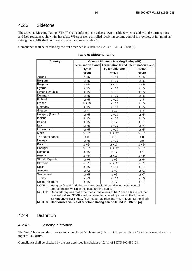
The Sidetone Masking Rating (STMR) shall conform to the value shown in table 6 when tested with the terminationsand feed resistances shown in that table. Where a user-controlled receiving volume control is provided, at its "nominal"setting the STMR shall conform to the value shown in table 6.
Compliance shall be checked by the test described in subclause 4.2.3 of I-ETS 300 480 [2].
Table 6: Sidetone rating
Country Value of Sidetone Masking Rating (dB)Termination a and
RfminTermination b and
Rf for sidetoneTermination c and
Rfmax
STMR STMR STMRAustria ≥ +5 ≥ +10 ≥ +5Belgium ≥ +5 ≥ +10 ≥ +5Bulgaria ≥ +5* ≥ +10* ≥ +5*Cyprus ≥ +5 ≥ +10 ≥ +5Czech Republic ≥ +5 ≥ +5 ≥ +5Denmark ≥ +5 ≥ +10 ≥ +5Finland ≥ +5 ≥ +10 ≥ 7France ≥ +10 ≥ +10 ≥ +5Germany ≥ +5 ≥ +10 ≥ +5Greece ≥ +7 ≥ 12 ≥ 7Hungary (1 and 2) ≥ +5 ≥ +10 ≥ +5Iceland ≥ +5 ≥ +10 ≥ +5Ireland ≥ +5 ≥ +7 ≥ +7Italy ≥ +5 ≥ +10 ≥ +4Luxembourg ≥ +5 ≥ +10 ≥ +5Malta ≥ +5* ≥ +10* ≥ +5*The Netherlands ≥ 0 ≥ 0 ≥ 0Norway ≥ +5 ≥ +10 ≥ 0Poland ≥ +5* ≥ +10* ≥ +5*Portugal ≥ +5* ≥ +10* ≥ +5*Romania ≥ +5 ≥ +7 ≥ 1Russia ≥ +5* ≥ +10* ≥ +5*Slovak Republic ≥ +6 ≥ +6 ≥ +6Slovenia ≥ +5* ≥ +10* ≥ +5*Spain ≥ +5 ≥ +10 ≥ +7Sweden ≥ +2 ≥ +2 ≥ +2Switzerland ≥ +5 ≥ +7 ≥ +7Turkey ≥ +5 ≥ +10 ≥ +5United Kingdom ≥ +5 ≥ +7 ≥ +7NOTE 1: Hungary (1 and 2) define two acceptable alternative loudness control
characteristics which in this case are the same.NOTE 2: Denmark requires that if the measured values of RLR and SLR are not the
nominal values, STMR shall be corrected accordingly, using the formula:STMRcorr.=STMRmeas.-(SLRmeas.-SLRnominal +RLRmeas-RLRnominal)
NOTE 3: Harmonized values of Sidetone Rating can be found in TBR 38 [4] .
4.2.4 Distortion
4.2.4.1 Sending distortion
The "total" harmonic distortion (summed up to the 5th harmonic) shall not be greater than 7 % when measured with aninput of -4,7 dBPa.
Compliance shall be checked by the test described in subclause 4.2.4.1 of I-ETS 300 480 [2].

ES 200 677 V1.2.1 (1998-03)15
4.2.4.2 Receiving distortion
The "total" harmonic distortion (summed up to the 5th harmonic) shall not be greater than 7 %, when measured with aninput electromotive force (e.m.f.) of -12 dBV.
Where a user-controlled receiving volume control is provided, the above requirement applies for the "nominal" settingof the volume control.
Compliance shall be checked by the test described in subclause 4.2.4.2 of I-ETS 300 480 [2].
4.2.4.3 Sidetone distortion
The "total" harmonic distortion (summed up to the 5th harmonic) shall not be greater than 10 % when measured with aninput of -4,7 dBPa. Where a user-controlled receiving volume control is provided, the above requirement applies for the"nominal" setting of the volume control.
Compliance shall be checked by the test described in subclause 4.2.4.3 of I-ETS 300 480 [2].
4.2.4.4 Sending power-handling capability
The total harmonic distortion (summed up to the 5th harmonic) shall be not greater than 10 % when a pure tone signal of1 000 Hz is applied at the Mouth Reference Point (MRP) at a Sound Pressure Level (SPL) of 5 dBPa.
Compliance shall be checked by the test described in subclause 4.2.4.4 of I-ETS 300 480 [2].
4.2.4.5 Receiving power-handling capability
The total harmonic distortion (summed up to the 5th harmonic) of the receiving direction signal shall be not greater than10 % when a pure sinusoidal signal of 1 V e.m.f. is supplied by the generator at a frequency of 1 000 Hz. Where auser-controlled receiving volume control is provided, the above requirement applies for the "nominal" setting of thevolume control.
Compliance shall be checked by the test described in subclause 4.2.4.5 of I-ETS 300 480 [2].
4.2.5 Linearity (variation of gain with input level)
4.2.5.1 Sending
With the value of Rf specified in table 1 as "for response test", the sensitivity determined with an input SPL of -4,7 dBPashall not differ by more than ±2 dB from the sensitivity determined with an input SPL of -19,7 dBPa.
Compliance shall be checked by the test described in subclause 4.2.5.1 of I-ETS 300 480 [2].
4.2.5.2 Receiving
With the value of Rf specified in table 1 as "for response test", the sensitivity determined with an input signal with ane.m.f. of -12 dBV shall not differ by more than ±2 dB from the sensitivity determined with an input signal with an e.m.f.of -32 dBV.
Where a user-controlled receiving volume control is provided, the above requirement applies for the "nominal" settingof the volume control.
Compliance shall be checked by the test described in subclause 4.2.5.2 of I-ETS 300 480 [2].

ES 200 677 V1.2.1 (1998-03)16
4.2.6 Noise
4.2.6.1 Sending noise
The psophometrically weighted noise produced by the apparatus in the sending direction shall not be greater than-64 dBmp.
Compliance shall be checked by the test described in subclause 4.2.6.1 of I-ETS 300 480 [2].
4.2.6.2 Receiving noise
The noise level measured in an artificial ear shall not be greater than -49 dBPa(A). Where a user-controlled receivingvolume control is provided, the above requirement applies for the "nominal" setting of the volume control.
Compliance shall be checked by the test described in subclause 4.2.6.2 of I-ETS 300 480 [2].
4.2.7 Echo return loss
The echo return loss shall not be less than 14 dB with respect to the impedance shown in figure 3.
270 ohms 750 ohms
150 nF
Figure 3: Terminating impedance
Compliance shall be checked by determination of the echo return loss as described in subclause 4.2.7 ofI-ETS 300 480 [2] at the maximum and minimum values specified for Rf.
4.2.8 Instability
Instability (sustained audible oscillations) shall not be induced when the apparatus is subjected to the conditionsspecified in the compliance test described in subclause 4.2.8 of I-ETS 300 480 [2]. Where a user-controlled receivingvolume control is provided, the above requirement applies for the maximum setting of the volume control.
5 Physical modules
5.1 HandsetThere is no requirement for handset shape.
NOTE: Telephony performance is dependent on good handset characteristics. CCITT Recommendation P.35 [6]contains some recommendations for handset dimensions which are known to give good handsetcharacteristics.

ES 200 677 V1.2.1 (1998-03)17
Annex A (normative):Maximum acoustically stimulated output
A.1 Maximum acoustically stimulated outputThe maximum signal generated as a result of any acoustic stimulus shall not be greater than 8 V peak-to-peak.
Compliance shall be checked by the test described in clause A.1 of I-ETS 300 480 [2].
NOTE: The signal to line at speech levels occurring in normal use is controlled by the SLR in subclause 4.2.2.1.

ES 200 677 V1.2.1 (1998-03)18
Annex B (informative):Acoustic shock
B.1 GeneralThe prevention of acoustic shock is a safety requirement outside the scope of the present document and arising from theLow Voltage Directive (73/23/EEC) [7]. In the absence of any relevant safety standard, a supplier's self declaration maybe based on the following recommendations.
The limits advised are based on sound pressure levels measured in an ITU-T Recommendation P.57 [8] type 1 artificialear. For other types of artificial ear different sound pressure levels may be required.
B.1.1 Continuous signalThe sound pressure level in the artificial ear should not exceed 24 dBPa (rms).
Compliance should be checked by the test described in clause B.1 of I-ETS 300 480 [2].
B.1.2 Peak signalThe receiving equipment should limit the peak sound pressure level in the artificial ear to less than 36 dBPa.
Conformance test methods are for further study. Until such methods exist, compliance should be checked by thesuppliers declaration of conformance.

ES 200 677 V1.2.1 (1998-03)19
Annex C (informative):Immunity to out-of-band signallingIn Germany and Switzerland, the out-of-band signalling used can seriously effect the speech performance of a connectedtelephony terminal. The following requirement is used to control the effect of meter pulses which are applied by thenetwork at each termination point.
C.1 SendingAn out-of-band signalling with a pulse ratio (1s "on" and 5s "off") should not cause the output signal to change by morethan 1 dB compared with the reference measurements.
Compliance should be checked by the test described in clause C.1 of I-ETS 300 480 [2] using a test signal of either16 kHz (DE) or 12 kHz (CH) with an e.m.f. of +20 dBV.
C.2 ReceivingAn out-of-band signalling with a pulse ratio (1s "on" and 5s "off") should not cause the output signal to change by morethan 1 dB compared with the reference measurements.
Compliance should be checked by the test described in clause C.2 of I-ETS 300 480 [2] using a test signal of either16 kHz (DE) or 12 kHz (CH) with an e.m.f. of +20 dBV.

ES 200 677 V1.2.1 (1998-03)20
Annex D (informative):Additional requirement for d.c. characteristics
D.1 IntroductionThe main part of the present document does not contain any requirements for d.c. characteristics because suchcharacteristics are normally part of the access requirements.
However, some networks require additional control of the d.c characteristics in order to satisfy requirements forinterworking via the network.
This necessitates a restriction in the range of d.c. characteristics of a voice terminal so that the local exchange can makean automatic assessment of the local loop resistance and, depending on the value so determined, insert additional loss inthe analogue part of 4-wire path in order to provide improved control of loudness and echo performance on short lines.
This automatic adjustment of loss is analogous to the manual setting of attenuation values of exchange loss padsdependent on the line length that is necessary in some other networks.
D.2 RequirementAs an example of such control of the d.c. characteristics, in the UK the following lower limit is added to the d.c. mask:
In addition to the requirements of subclause 2.3 of ETS 300 001 [1], when the leads intended for connection tothe PSTN are connected to a voltage source of 50 V d.c. in series with a 400 ohm resistor and a variable resistor,the steady-state voltage measured at the terminals of the TE under test should be greater than the limits given intable D.1.
Table D.1: Lower limit curves for d.c.characteristics
Current (mA) Voltage (V)12,5 012,5 2,320,0 6,0
100,0 10,0

ES 200 677 V1.2.1 (1998-03)21
History
Document history
V1.2.1 December 1997 Membership Approval Procedure MV 9809: 1997-12-30 to 1998-02-27
V1.2.1 March 1998 Publication
ISBN 2-7437-2044-1Dépôt légal : Mars 1998