erhic design status v.ptitsyn for the erhic design team
Post on 21-Dec-2015
221 views
TRANSCRIPT

eRHIC design status
V.Ptitsynfor the eRHIC design team
V.Ptitsyn, EIC Collaboration Meeting, 05/19/08
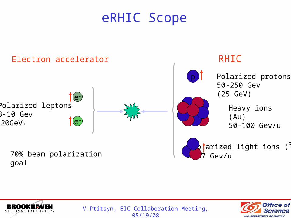
eRHIC Scope
Polarized leptons3-10 Gev (20GeV)
Polarized light ions (3He)167 Gev/u
Heavy ions (Au)50-100 Gev/u
Polarized protons50-250 Gev(25 GeV)
Electron accelerator RHIC
e-
e+
p
70% beam polarization goal
V.Ptitsyn, EIC Collaboration Meeting, 05/19/08
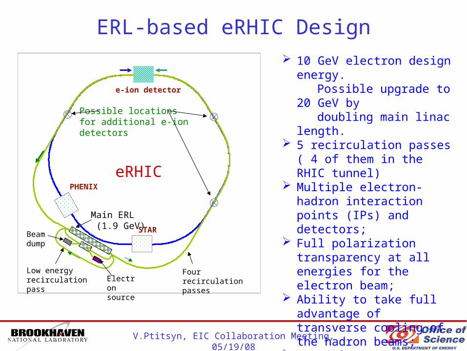
ERL-based eRHIC Design 10 GeV electron design energy. Possible upgrade to 20 GeV by doubling main linac length. 5 recirculation passes ( 4 of them
in the RHIC tunnel) Multiple electron-hadron
interaction points (IPs) and detectors;
Full polarization transparency at all energies for the electron beam;
Ability to take full advantage of transverse cooling of the hadron beams;
Possible options to include polarized positrons: compact storage ring; compton backscattered; undulator-based. Though at lower luminosity.
Four recirculation passes
PHENIX
STAR
e-ion detector
eRHIC
Main ERL (1.9 GeV)
Low energy recirculation pass
Beam dump
Electronsource
Possible locationsfor additional e-ion detectors

ERL-based eRHIC Parameters: e-p modeHigh energy setup Low energy setup
p e p e
Energy, GeV 250 10 50 3
Number of bunches 166 166
Bunch spacing, ns 71 71 71 71
Bunch intensity, 1011 2 1.2 2 1.2
Beam current, mA 420 260 420 260
Normalized 95% emittance, mm.mrad 6 460 6 570
Rms emittance, nm 3.8 4 19 16.5
*, x/y, cm 26 25 26 30
Beam-beam parameters, x/y 0.015 0.59 0.015 0.47
Rms bunch length, cm 20 1 20 1
Polarization, % 70 80 70 80
Peak Luminosity, 1.e33 cm-2s-1
Aver.Luminosity, 1.e33 cm-2s-1
2.6 0.53
0.87 0.18
Luminosity integral /week, pb-1 530 105
If effective high energy transverse cooling becomes possible the proton emittance and electron beam current can be reduced simultaneously, keeping the same luminosity.

ERL-based eRHIC Parameters: e-Au modeHigh energy setup Low energy setup
Au e Au e
Energy, GeV 100 10 50 3
Number of bunches 166 166
Bunch spacing, ns 71 71 71 71
Bunch intensity, 1011 1.1 1.2 1.1 1.2
Beam current, mA 180 260 180 260
Normalized 95% emittance, mm.mrad 2.4 460 2.4 270
Rms emittance, nm 3.7 3.8 7.5 7.8
*, x/y, cm 26 25 26 25
Beam-beam parameters, x/y 0.015 0.26 0.015 0.43
Rms bunch length, cm 20 1 20 1
Polarization, % 0 0 0 0
Peak e-nucleon luminosity, 1.e33 cm-2s-1
Average e-nucleon luminosity, 1.e33 cm-2s-1
2.9 1.5
1.0 0.5
Luminosity integral /week, pb-1 580 290
V.Ptitsyn, EIC Collaboration Meeting, 05/19/08
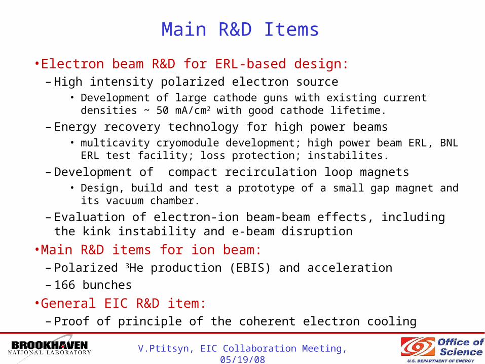
Main R&D Items
•Electron beam R&D for ERL-based design:– High intensity polarized electron source
• Development of large cathode guns with existing current densities ~ 50 mA/cm2 with good cathode lifetime.
– Energy recovery technology for high power beams• multicavity cryomodule development; high power beam ERL, BNL ERL test facility;
loss protection; instabilites.
– Development of compact recirculation loop magnets• Design, build and test a prototype of a small gap magnet and its vacuum chamber.
– Evaluation of electron-ion beam-beam effects, including the kink instability and e-beam disruption
•Main R&D items for ion beam:– Polarized 3He production (EBIS) and acceleration
– 166 bunches
•General EIC R&D item:– Proof of principle of the coherent electron cooling
V.Ptitsyn, EIC Collaboration Meeting, 05/19/08
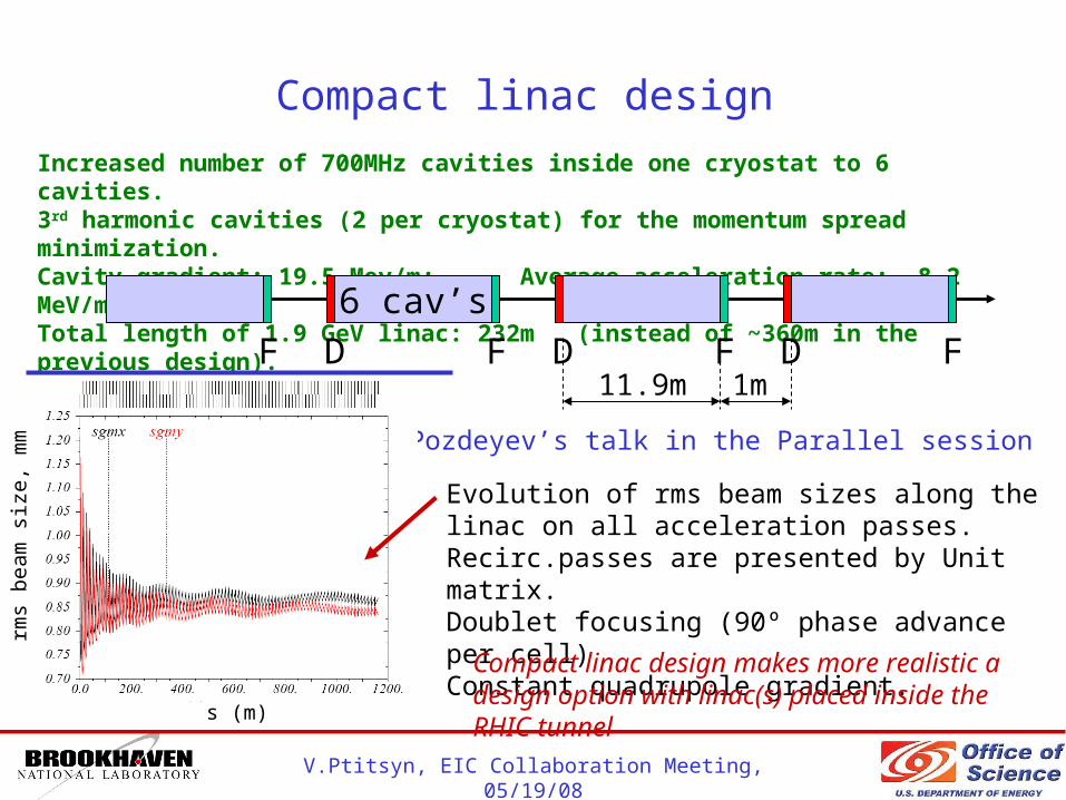
Compact linac design
Increased number of 700MHz cavities inside one cryostat to 6 cavities.3rd harmonic cavities (2 per cryostat) for the momentum spread minimization.Cavity gradient: 19.5 Mev/m; Average acceleration rate: 8.2 MeV/m;Total length of 1.9 GeV linac: 232m (instead of ~360m in the previous design). 6 cav’s
D F D11.9m 1m
D FF F
Evolution of rms beam sizes along the linac on all acceleration passes. Recirc.passes are presented by Unit matrix.Doublet focusing (90º phase advance per cell)Constant quadrupole gradient.
E.Pozdeyev’s talk in the Parallel session
Compact linac design makes more realistic a design option with linac(s) placed inside the RHIC tunnel
rms
beam
siz
e, m
m
s (m)
V.Ptitsyn, EIC Collaboration Meeting, 05/19/08
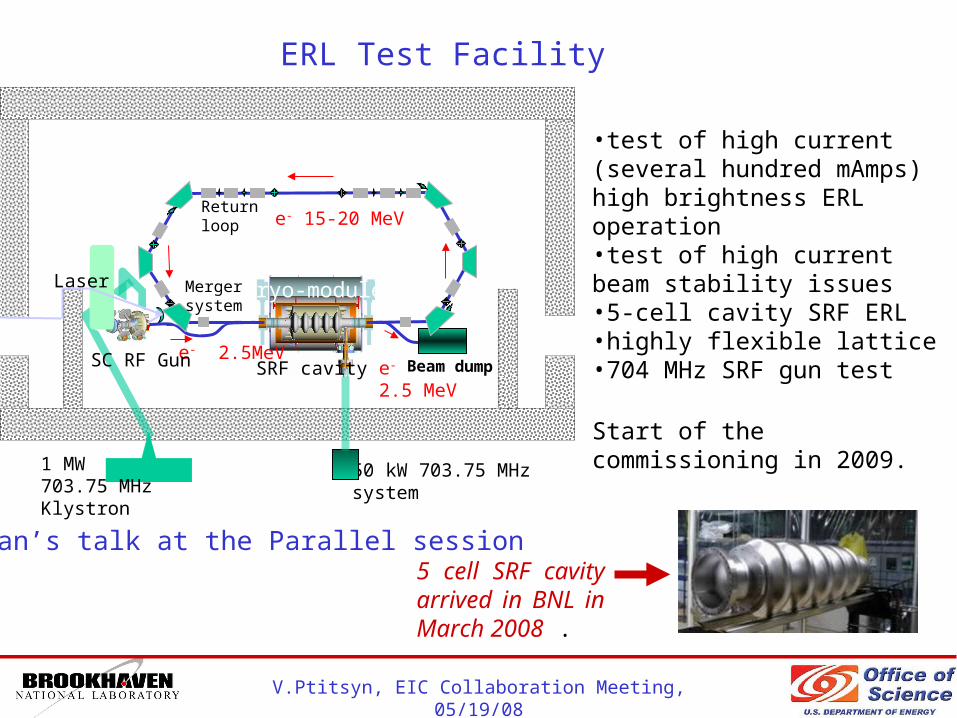
ERL Test Facility
50 kW 703.75 MHzsystem
Cryo-module
SRF cavity
1 MW 703.75 MHzKlystron
e- 2.5MeV
Laser
SC RF Gun e- 2.5 MeV
Beam dump
e- 15-20 MeV
Merger system
Return loop
•test of high current (several hundred mAmps) high brightness ERL operation•test of high current beam stability issues•5-cell cavity SRF ERL •highly flexible lattice•704 MHz SRF gun test
Start of the commissioning in 2009.
D.Kayran’s talk at the Parallel session5 cell SRF cavity arrived in BNL in March 2008 .
V.Ptitsyn, EIC Collaboration Meeting, 05/19/08
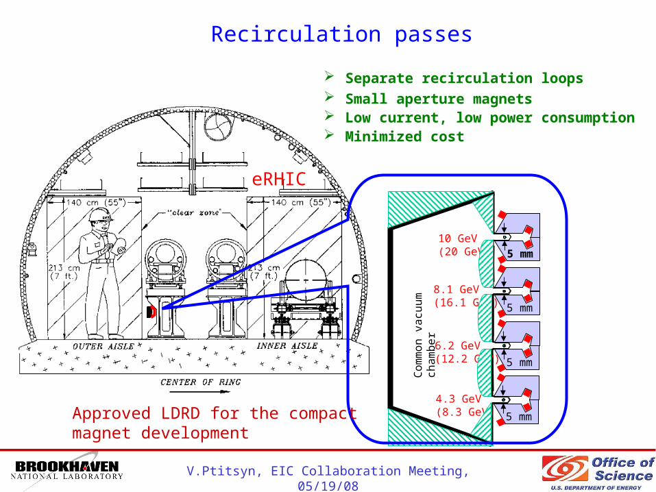
eRHIC
Recirculation passes
Separate recirculation loops Small aperture magnets Low current, low power consumption Minimized cost
5 mm
5 mm
5 mm
5 mm
10 GeV (20 GeV)
8.1 GeV (16.1 GeV)
6.2 GeV (12.2 GeV)
4.3 GeV (8.3 GeV)
Com
mon v
acu
um
ch
am
ber
Approved LDRD for the compact magnet development

V.Ptitsyn, EIC Collaboration Meeting, 05/19/08
Recirculation Pass Optics Modification
The optics based on Flexible Momentum Compaction cell provides achromatic and isochronal transfer through each arc and allows for flexible adjustment of R56 parameter.
More details in V.Ptitsyn’s talk in the Parallel session
Other features:-phase trombone (in the straight sections)-path length control (at 12 o’clock region)-initial design for separator/merger
V.Ptitsyn, EIC Collaboration Meeting, 05/19/08
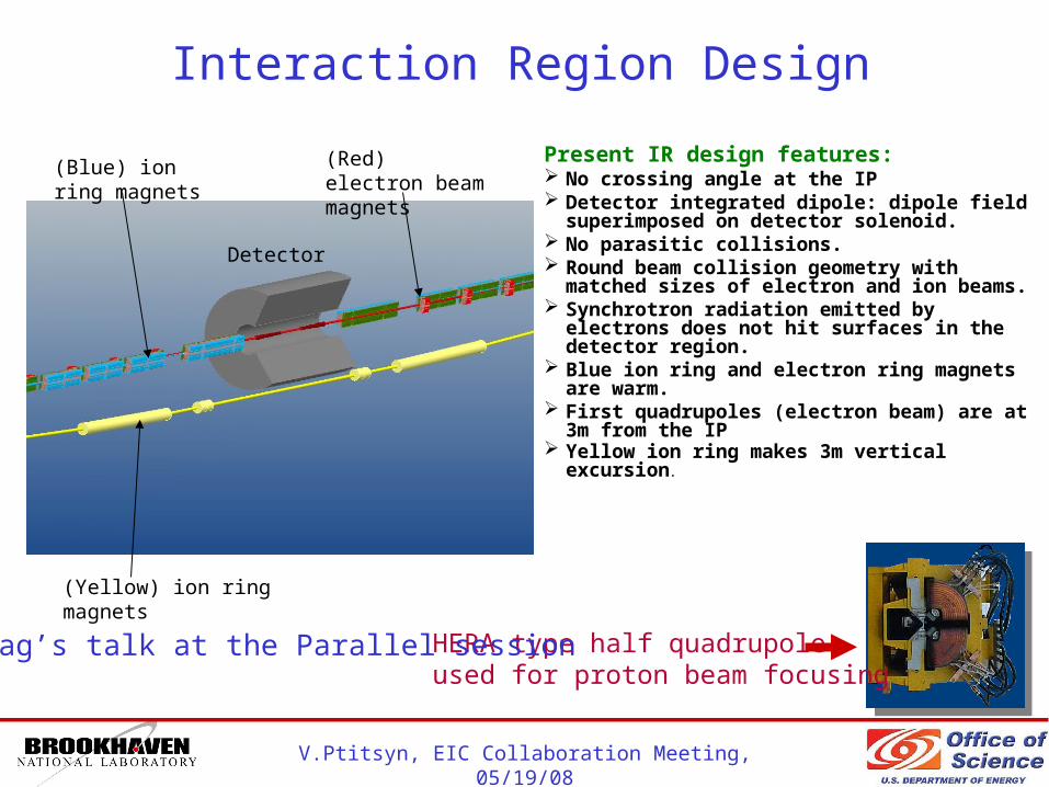
Interaction Region Design
Present IR design features: No crossing angle at the IP Detector integrated dipole: dipole field
superimposed on detector solenoid. No parasitic collisions. Round beam collision geometry with matched
sizes of electron and ion beams. Synchrotron radiation emitted by electrons
does not hit surfaces in the detector region. Blue ion ring and electron ring magnets are
warm. First quadrupoles (electron beam) are at 3m
from the IP Yellow ion ring makes 3m vertical excursion.
(Blue) ion ring magnets
(Red) electron beam magnets
(Yellow) ion ring magnets
Detector
HERA type half quadrupoleused for proton beam focusing
C.Montag’s talk at the Parallel session
V.Ptitsyn, EIC Collaboration Meeting, 05/19/08
Beam-beam interaction studies
Several features of the beam-beam interactions are under consideration:• The kink instability is stabilized for design beam intensities by proper choice
of the chromaticity.
• Techniques for compensation of the mismatch caused by the beam-beam are under consideration.
• Both electron beam disruption and proton beam-beam parameter benefit from lower * of electrons.
• More investigations are underway for incoherent proton beam emittance growth in the presence of electron pinch, including the optimal choice of the working point.
• For details see a presentation in the Parallel session as well as a talk at previous meeting.

V.Ptitsyn, EIC Collaboration Meeting, 05/19/08
Effect of electron pitching on the proton beam
The electron beam is focused by strong beam-beam force.That in turn leads to larger proton beam-beam parameter
031.0
054.0max
ave
014.0
022.0max
ave
Proper selectionof the IP and -waist isimportant to minimize the proton beam-beam parametere-beam
V.Ptitsyn, EIC Collaboration Meeting, 05/19/08
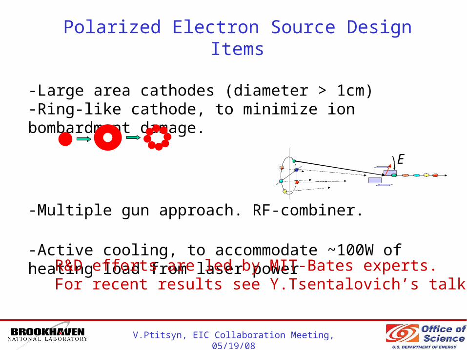
Polarized Electron Source Design Items
-Large area cathodes (diameter > 1cm)-Ring-like cathode, to minimize ion bombardment damage.
-Multiple gun approach. RF-combiner.
-Active cooling, to accommodate ~100W of heating load from laser power
R&D efforts are led by MIT-Bates experts.For recent results see Y.Tsentalovich’s talk
E
V.Ptitsyn, EIC Collaboration Meeting, 05/19/08
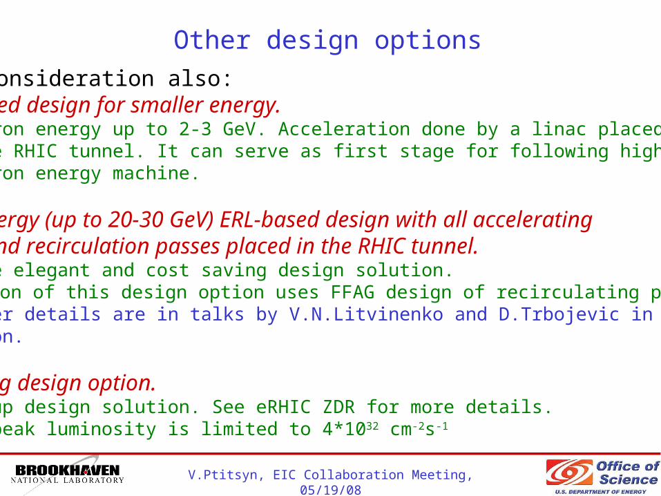
Other design options
Under consideration also:ERL-based design for smaller energy. Electron energy up to 2-3 GeV. Acceleration done by a linac placed in the RHIC tunnel. It can serve as first stage for following higher electron energy machine.
High energy (up to 20-30 GeV) ERL-based design with all accelerating linacs and recirculation passes placed in the RHIC tunnel. Can be elegant and cost saving design solution. Variation of this design option uses FFAG design of recirculating passses. Further details are in talks by V.N.Litvinenko and D.Trbojevic in Parallel Session.
Ring-ring design option. Backup design solution. See eRHIC ZDR for more details. The peak luminosity is limited to 4*1032 cm-2s-1
V.Ptitsyn, EIC Collaboration Meeting, 05/19/08
Summary
• The accelerator design work continues on various aspects of the ERL-based design of eRHIC, which presently aims to provide e-p average luminosity at 1033 cm-2s-1 level.
• Recent advances are done in several design areas, including linac design, recirculating pass optics, studies of beam-beam effects.
• R&D subjects, such as polarized source development, ERL test facility and compact magnet design, are supported by financing. So, one can expect advances on those directions in coming 2 years.
• Other design options under consideration: ERL-based designs with linac(s) in the tunnel and the ring-ring design.