erdc/itl tr-17-1 'an investigation of corrosion mitigation … · 2018-01-16 · this...
TRANSCRIPT

ERD
C/IT
L TR
-17-
1
Navigation Systems Research Program
An Investigation of Corrosion Mitigation Strategies for Aging Post-Tensioned Cables
Info
rmat
ion
Tech
nolo
gy L
abor
ator
y
Ernest L. Miller, Barry C. White, Richard W. Haskins, Robert M. Ebeling, and James A. Evans
January 2017
Approved for public release; distribution is unlimited.

The US Army Engineer Research and Development Center (ERDC) solves the nation’s toughest engineering and environmental challenges. ERDC develops innovative solutions in civil and military engineering, geospatial sciences, water resources, and environmental sciences for the Army, the Department of Defense, civilian agencies, and our nation’s public good. Find out more at www.erdc.usace.army.mil.
To search for other technical reports published by ERDC, visit the ERDC online library at http://acwc.sdp.sirsi.net/client/default.
Navigation Systems Research Program ERDC/ITL TR-17-1 January 2017
An Investigation of Corrosion Mitigation Strategies for Aging Post-Tensioned Cables
Ernest L. Miller, Barry C. White, Richard W. Haskins, Robert M. Ebeling, and James A. Evans Information Technology Laboratory U.S. Army Engineer Research and Development Center 3909 Halls Ferry Road Vicksburg, MS 39180-6199
Final report Approved for public release; distribution is unlimited.
Prepared for U.S. Army Corps of Engineers Washington, DC 20314-1000
Under Probabilistic Assessment of the Reduced Capacity of Multistrand Post Tensioned Ground Anchorage Due to Tendon Corrosion Work Unit number L9C833

ERDC/ITL TR-17-1 ii
Abstract
Over the past 50 years, the U.S. Army Corps of Engineers has been upgrading its projects by installing high-capacity, post-tensioned foundation anchors. These anchors are typically made with seven-wire strand cables. The purpose of these anchors has been to achieve structural stability for Corps hydraulic concrete structures (e.g., locks, dams, approach walls) and/or to remediate cracked concrete monoliths. Substantial improvements have been made in the methods that protect multistrand anchor systems from corrosion since they were first used in Corps projects, but the corrosion of older multistrand anchorage systems is still a major concern.
Previous technical reports from this U.S. Army Engineer Research and Development Center (ERDC) research team have discussed ways to measure and assess corrosion and capacity losses due to corrosion of multistrand cables used for these anchor systems, as well as perform statistical estimates and predictions of the reduced cable capacity. This technical report explores state-of-the-art existing corrosion mitigation and repair techniques that are applied in other systems, and turns a critical eye toward how these techniques could be applied for anchors supporting the Corps mass concrete hydraulic structures. Nine techniques were examined and the pros and cons of these methods, with respect to the Corps structure environment, are discussed.
DISCLAIMER: The contents of this report are not to be used for advertising, publication, or promotional purposes. Citation of trade names does not constitute an official endorsement or approval of the use of such commercial products. All product names and trademarks cited are the property of their respective owners. The findings of this report are not to be construed as an official Department of the Army position unless so designated by other authorized documents. DESTROY THIS REPORT WHEN NO LONGER NEEDED. DO NOT RETURN IT TO THE ORIGINATOR.
ERDC/ITL TR-17-1 iii
Contents Abstract .......................................................................................................................................................... ii
Figures and Tables ......................................................................................................................................... v
Preface ...........................................................................................................................................................vii
Unit Conversion Factors ............................................................................................................................. ix
1 Introduction ............................................................................................................................................ 1 1.1 Background .................................................................................................................... 1 1.2 Post-Tensioning Institute (PTI) Guidelines .................................................................... 6 1.3 The need for corrosion mitigation ................................................................................. 9
2 Corrosion Mitigation Strategies....................................................................................................... 10 2.1 Cathodic protection ..................................................................................................... 10
2.1.1 Passive cathodic protection: Pro ................................................................................. 18 2.1.2 Passive cathodic protection: Con ................................................................................ 18 2.1.3 Active cathodic protection: Pro.................................................................................... 18 2.1.4 Active cathodic protection: Con ................................................................................... 18
2.2 Cable drying ................................................................................................................. 19 2.2.1 Cable drying: Pro .......................................................................................................... 21 2.2.2 Cable drying: Con ......................................................................................................... 21
2.3 Re-grouting ................................................................................................................... 21 2.3.1 Re-grouting: Pro ........................................................................................................... 23 2.3.2 Re-grouting: Con ........................................................................................................... 24
2.4 Rust remover ................................................................................................................ 24 2.4.1 Rust remover: Pro ........................................................................................................ 25 2.4.2 Rust remover: Con ....................................................................................................... 25
2.5 Re-greasing .................................................................................................................. 26 2.5.1 Re-greasing: Pro ........................................................................................................... 29 2.5.2 Re-greasing: Con .......................................................................................................... 29
2.6 Increase pH of free space and/or grout environment ............................................... 29 2.6.1 Increased pH: Pro ......................................................................................................... 31 2.6.2 Increased pH: Con ........................................................................................................ 32
2.7 Chemical impregnation though spaces between cable strands ............................... 32 2.7.1 Chemical impregnation: Pro ........................................................................................ 34 2.7.2 Chemical impregnation: Con ....................................................................................... 34
2.8 Concrete healer/sealers ............................................................................................. 34 2.8.1 Concrete healer/sealers: Pro ...................................................................................... 36 2.8.2 Concrete healer/sealers: Con ..................................................................................... 36
2.9 Relief water wells and foundation drains ................................................................... 36 2.9.1 Relief wells: Pro ............................................................................................................ 38 2.9.2 Relief wells: Con ........................................................................................................... 38
ERDC/ITL TR-17-1 iv
3 Summary and Conclusions ............................................................................................................... 39 3.1 Overview: Corrosion in the multistrand anchor environment .................................... 39 3.2 Summary: Corrosion mitigation techniques explored................................................ 40 3.3 Conclusions .................................................................................................................. 41
References ................................................................................................................................................... 44
Appendix A ................................................................................................................................................... 48
Appendix B ................................................................................................................................................... 50
Report Documentation Page
ERDC/ITL TR-17-1 v
Figures and Tables
Figures
Figure 1.1. Post-tensioned anchorage system remediation of John Day Lock in 1981 using 73 tie-down anchors. ......................................................................................................................... 1 Figure 1.2. The installation of a post-tensioned anchor system at John Day Lock, pictures of its (then) new anchor head and its (current) corroded anchor head spewing water, and rate of anchor loss with time (due to corrosion). ....................................................................................... 2 Figure 1.3. Inspection results for lift-off tests at the south lock wall at John Day Lock. ...................... 4 Figure 1.4. Example of a lift-off test for anchor 11-32 at the south lock wall at John Day Lock. ................................................................................................................................................................. 5 Figure 1.5. Post-tensioned anchor recommendations (PCI 1974). ......................................................... 8 Figure 2.1. The process of pitting corrosion (Lee and Zielske 2014). ................................................... 11 Figure 2.2. Idealization of active (impress current) cathodic protection as applied to the cables of a lock wall remediated by using post-tensioned anchorage. ................................................ 12 Figure 2.3. Example of anode protecting ship’s hull (cathode). This is the U.S. Army Corps of Engineers Dredge Jadwin in dry dock. The anodes are the metal bars welded to the hull of the ship. ..................................................................................................................................................... 13 Figure 2.4. Example of anode protecting ship’s hull (cathode). This is the U.S. Army Corps of Engineers Dredge Jadwin in dry dock. Note the partially consumed anode (to the right) at the entrance of the engine cooling water intake. ................................................................................ 13 Figure 2.5. Electron microscope view of hydrogen embrittlement (photo courtesy of NASA Corrosion Technology Laboratory). ............................................................................................................. 16 Figure 2.6. Depiction of potential measurement between anode and reference electrode (Chess and Gronvoid 1996). ....................................................................................................................... 16 Figure 2.7. Idealization of passive (sacrificial anode) cathodic protection as applied to the cables of a lock wall remediated by using post-tensioned anchorage. ................................................ 17 Figure 2.8. Relationship between relative humidity and the rate of corrosion of iron in air with 0.01% sulfur dioxide (Uhlig 1948). .................................................................................................... 19 Figure 2.9. Illustration of a possible cable drying system as applied to the cables of a lock wall remediated by using post-tensioned anchorage.............................................................................. 20 Figure 2.10. Example of accelerated corrosion due to biological agents in existing grease (Ebeling et al. 2013). ................................................................................................................................... 27 Figure 2.11. Freshly greased anchor head (Cornforth Consultants 2009). ......................................... 27 Figure 2.12. Grease with biological growth at John Day lock when anchor head was removed (Ebeling et al. 2013). ................................................................................................................... 28 Figure 2.13. Simple scale of alkaline-acid to pH number. ...................................................................... 30 Figure 2.14. The effect of pH on corrosion (Uhlig 1948). ....................................................................... 30 Figure 2.15. Representation of chemical impregnation of multistranded cables and surrounding grout. ........................................................................................................................................ 33 Figure 2.16. Products used in evaluation of healer/sealers study (Soltesz 2010). ............................ 35 Figure 2.17. Illustration representing relief well (HQUSACE 1992). ...................................................... 37
ERDC/ITL TR-17-1 vi
Figure A.1. Flowchart of decision-making process between implementing active and passive cathodic protection, after HQUSACE 2005 p.2-3. ..................................................................... 49
Tables
Table 1.1. Corrosion Protection Requirements (after PTI 2004). ............................................................ 9
ERDC/ITL TR-17-1 vii
Preface
Often-used techniques for protection from corrosion, such as cathodic protection to methods to remove corrosion are discussed. Assessment of these techniques are qualified by discussions of how these methods would access the cables, possible collateral impacts of their usage, their effectiveness, etc.
This investigation and report was authorized by Headquarters, U.S. Army Corps of Engineers (HQUSACE), and was performed from June 2014 to December 2014. It was published under the Navigation Systems Research Program, Work Unit “Probabilistic Assessment of the Reduced Capacity of Multistrand Post Tensioned Ground Anchorage Due to Tendon Corrosion.” Jeff McKee was the HQUSACE Navigation Business Line Manager; Charles Wiggins was the Program Manager for the Navigation Systems Research Program, Coastal and Hydraulics Laboratory (CHL), ERDC; and Jeff Lillycrop was Technical Director, CHL-ERDC. The research investigation and the Principal Investigator of the work unit was led by Dr. Robert M. Ebeling, Information Technology Laboratory (ITL), under the general supervision of Dr. Reed L. Mosher, Director, ITL; Patti S. Duett, Deputy Director, ITL. This work effort was also conducted under the general supervision of Elias Arredondo, Dr. Kevin Abraham, and Dr. Jerrell R. Ballard, each as Acting Chief, Computational Science and Engineering Division (CSED), ITL.
Special thanks is given to Dr. Robert Moser, Geotechnical and Structures Laboratory (GSL), for the insight and collaborative efforts he provided on this project; Dr. Brandon Lafferty, Environmental Laboratory (EL), for the insight on sensors for this project; Brian Green, GSL, for the information he provided regarding grout for this project; Mike Wallace, Mobile District, for his information on cathodic protection of structures; Patrick Chambers, River Operations Branch Vicksburg District, for his information on boat based cathodic protection.
The authors also wish to acknowledge the following contributors who provided information in their field of specialty: Walt Hanford of Vector Corrosion for information on the chemical impregnation topic; Tom McKigney of Brance Krachy for the information on the subject of active

ERDC/ITL TR-17-1 viii
cathodic protection; and Dave Johnson of Galvotec for the information on the subject of passive and active cathodic protection of multistranded cables inside a small duct.
At the time of publication, COL Bryan S. Green was Commander of ERDC, and Dr. Jeffery P. Holland was Director of ERDC.
ERDC/ITL TR-17-1 ix
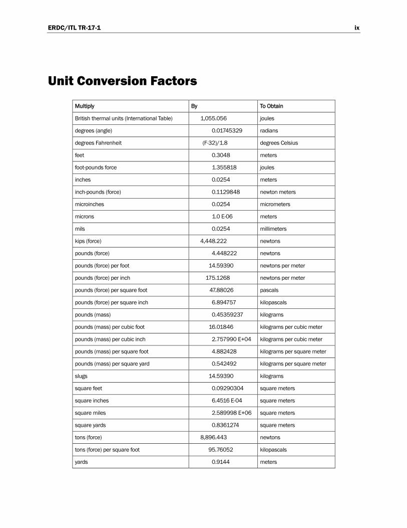
Unit Conversion Factors
Multiply By To Obtain
British thermal units (International Table) 1,055.056 joules
degrees (angle) 0.01745329 radians
degrees Fahrenheit (F-32)/1.8 degrees Celsius
feet 0.3048 meters
foot-pounds force 1.355818 joules
inches 0.0254 meters
inch-pounds (force) 0.1129848 newton meters
microinches 0.0254 micrometers
microns 1.0 E-06 meters
mils 0.0254 millimeters
kips (force) 4,448.222 newtons
pounds (force) 4.448222 newtons
pounds (force) per foot 14.59390 newtons per meter
pounds (force) per inch 175.1268 newtons per meter
pounds (force) per square foot 47.88026 pascals
pounds (force) per square inch 6.894757 kilopascals
pounds (mass) 0.45359237 kilograms
pounds (mass) per cubic foot 16.01846 kilograms per cubic meter
pounds (mass) per cubic inch 2.757990 E+04 kilograms per cubic meter
pounds (mass) per square foot 4.882428 kilograms per square meter
pounds (mass) per square yard 0.542492 kilograms per square meter
slugs 14.59390 kilograms
square feet 0.09290304 square meters
square inches 6.4516 E-04 square meters
square miles 2.589998 E+06 square meters
square yards 0.8361274 square meters
tons (force) 8,896.443 newtons
tons (force) per square foot 95.76052 kilopascals
yards 0.9144 meters
ERDC/ITL TR-17-1 1
1 Introduction
1.1 Background
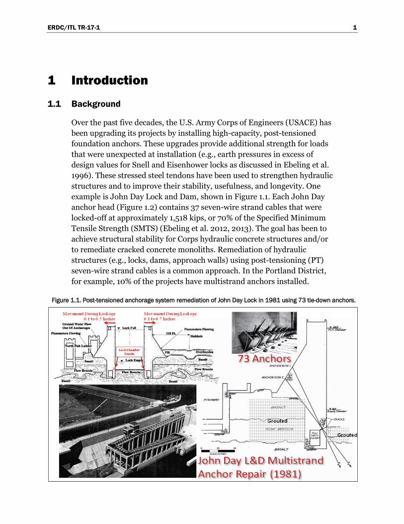
Over the past five decades, the U.S. Army Corps of Engineers (USACE) has been upgrading its projects by installing high-capacity, post-tensioned foundation anchors. These upgrades provide additional strength for loads that were unexpected at installation (e.g., earth pressures in excess of design values for Snell and Eisenhower locks as discussed in Ebeling et al. 1996). These stressed steel tendons have been used to strengthen hydraulic structures and to improve their stability, usefulness, and longevity. One example is John Day Lock and Dam, shown in Figure 1.1. Each John Day anchor head (Figure 1.2) contains 37 seven-wire strand cables that were locked-off at approximately 1,518 kips, or 70% of the Specified Minimum Tensile Strength (SMTS) (Ebeling et al. 2012, 2013). The goal has been to achieve structural stability for Corps hydraulic concrete structures and/or to remediate cracked concrete monoliths. Remediation of hydraulic structures (e.g., locks, dams, approach walls) using post-tensioning (PT) seven-wire strand cables is a common approach. In the Portland District, for example, 10% of the projects have multistrand anchors installed.
Figure 1.1. Post-tensioned anchorage system remediation of John Day Lock in 1981 using 73 tie-down anchors.
ERDC/ITL TR-17-1 2
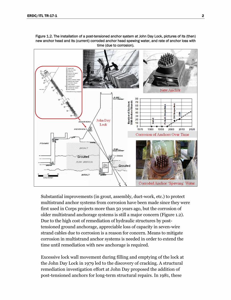
Figure 1.2. The installation of a post-tensioned anchor system at John Day Lock, pictures of its (then) new anchor head and its (current) corroded anchor head spewing water, and rate of anchor loss with
time (due to corrosion).
Substantial improvements (in grout, assembly, duct-work, etc.) to protect multistrand anchor systems from corrosion have been made since they were first used in Corps projects more than 50 years ago, but the corrosion of older multistrand anchorage systems is still a major concern (Figure 1.2). Due to the high cost of remediation of hydraulic structures by post-tensioned ground anchorage, appreciable loss of capacity in seven-wire strand cables due to corrosion is a reason for concern. Means to mitigate corrosion in multistrand anchor systems is needed in order to extend the time until remediation with new anchorage is required.
Excessive lock wall movement during filling and emptying of the lock at the John Day Lock in 1979 led to the discovery of cracking. A structural remediation investigation effort at John Day proposed the addition of post-tensioned anchors for long-term structural repairs. In 1981, these

ERDC/ITL TR-17-1 3
repairs began. The Portland District installed 73 post-tensioned anchors; each anchor consisted of 37 seven-strand cables of 0.6 in. diameter that were oriented to pass through the cracked concrete between the lock wall chamber and the fill/empty culvert wall on the locking chamber side of the culvert (lower left figure in Figure 1.2). A schematic diagram of the anchorage installed at John Day Lock is shown in the upper left of Figure 1.2. This post-tensioned anchor consists of five zones; the anchor head region, the anchor pedestal, the free stressing length, an inflatable packer, and the tension bond length. The free stressing length consists of greased, sheathed cables. Portland District engineers designed the John Day anchors for infrequent post-tensioning with time, as deemed necessary. A process of three-stage grouting was used over the tendon bond length. Individual sheaths were placed around each strand in which the load transfer (to the surrounding concrete monolith in which it is encased) does not take place. Inspections between 1981 and 1995 showed no broken strands; therefore, inspections were halted in 1995. Between 2001 and 2004, John Day Lock’s foundation was again inspected and was given the recommendation that various anchors be tested to confirm load capacity. In 2003 and again in 2008, all of the anchors were visually inspected, tested, and determined to be good, although broken strands were discovered. However, it was discovered that between 2003 and 2008 there was an 11% increase of anchors with visible damage. In 2011, the John Day Lock Multistrand Anchor Meeting was held at Portland District Headquarters, where these anchors and research plans were discussed to determine capacity and the effects of corrosion (Ebeling et al. 2012).
The Corps of Engineers completed detailed inspections and lift-off tests in 2003 and 2008 at John Day Lock. Cornforth Consultants (2009)1 discusses 21 lift-off tests conducted on the 37 seven-strand anchors at John Day Lock in 2008, and the processing of these field measurements taken to assess current PT anchorage capacity and the state of the anchors. The lift-off testing procedure and these results are summarized in Heslin et al. (2009). Figure 1.3 summarizes these lift-off tests conducted on the south lock wall of John Day Lock.
Cornforth Consultants (2009) and Heslin et al. (2009) discuss the three-stage, lift-off testing method. Figure 1.4 shows a typical lift-off test for the corroded anchor 11-32 that exhibits a reduced PT value of 920 kips. 1 Cornforth Consultants. 2009. Anchor inspection and lift-off testing, John Day Dam Navigation Lock,
unpublished Letter Report to Portland District, U.S. Army Corps of Engineers.

ERDC/ITL TR-17-1 4
Figure 1.3. Inspection results for lift-off tests at the south lock wall at John Day Lock.
Cornforth Consultants (2009) and Heslin et al. (2009) observed that the anchors could be grouped into damaged and undamaged tendons using a combination of visual inspections and interpreted results of lift-off tests. For the anchors with undamaged tendons, the John Day lift-off loads were 85-90% of the values at installation due to stress relaxation. The damaged tendons had a significant reduction in PT from the PT value at installation. The anchor measurements, which are highlighted in red and orange, can be seen in Figure 1.3.

ERDC/ITL TR-17-1 5
Figure 1.4. Example of a lift-off test for anchor 11-32 at the south lock wall at John Day Lock.
In the middle right of Figure 1.2, Portland District’s assessment of the number of anchors with broken strands over time is shown. The data indicates that more corroded strands will break over time. This observation is supported by the fact that inspections have shown that the number of anchors with visibly damaged strands increased by 11% between 2003 and 2008. Cornforth Consultants (2009) interpretation of 2008 John Day Lock data suggests that each year that passes would result in a 3-5% increase in the number of anchors with damaged strands. Heslin et al. (2009) observes that lift-off tests in 2008 had lift-off loads that were roughly 5% lower than the same anchors tested in 2003.
In 2012, ERDC was involved with the disassembly of two highly corroded John Day anchor heads that the results from the 2009 Cornforth Consultants lift-off tests had shown to be no longer effective for bearing loads (Ebeling et al. 2013). Based on ERDC’s field investigation, one speculative finding was that the two analyzed anchor heads might have stopped taking grout through the lower stage grout tubes during construction. This would explain the open grout-vent tubes that should have ended up filled with grout. The two disassembled anchor heads were

ERDC/ITL TR-17-1 6
the worst case in terms of leakage, load loss, and so forth according to visual inspection. It was not conclusive that this stoppage of grout was the primary deterioration problem for all of the corroded multistrand anchors at John Day.
The problems encountered at John Day Lock illustrate the influence of placement problems used for corrosion protection in post-tensioned anchorage.
1.2 Post-Tensioning Institute (PTI) Guidelines
According to a history compiled by Heslin et al. (2009), post-tensioned anchorage has been used to reinforce structures in the U.S. since the 1960’s. During that time, there were no engineering guidelines for the installation of post-tensioned anchorage, but since this need was recognized, the Post-Tensioning Division of the Prestressed Concrete Institute (PCI), which was formed in 1974, issued a set of guidelines. This Division later formed an independent organization, the Post-Tensioning Institute (PTI), in 1976.
In 1980, PTI issued the First Edition of Recommendations for Prestressed Rock and Soil Anchors (PTI Recommendations). These recommendations were adopted and reprinted by USACE with editions released in 1986, 1996, and 2004. It is sobering to realize that approximately 20,000 anchors were installed prior to 1996 in the U.S. with older guidance. Even given that most corrosion is attributable to poor design and construction techniques, the large number of anchors implies that even if only a small percent were poorly constructed under old PTI guidance, hundreds of anchors need this type of remediation.
The PTI is a nonprofit organization dedicated to the advancement of the post-tensioning construction method (PTI Recommendations 1986-2004). The PTI guidelines for post-tensioned cables are for new construction as well as repair. Bringing them up to the current 2004 PTI guidelines (PTI Recommendations 2004) would consist of upgrading the existing post-tensioned cables and their anchors or starting over and constructing new post-tensioned cable anchors on the lock wall.
In 1974, it was recommended that post-tensioned cable anchors be grouted for corrosion control. For two-stage grouting, sheathing could be omitted (sheathing was not used for corrosion protection, but was used to
ERDC/ITL TR-17-1 7
separate the cables from the grout). “Permanent” protection was defined as three years or more (PCI 1974).
By 1980, grouting was the number one corrosion mitigator for the bond length (Figure 1.5). Permanent protection was defined as 18 months or more. Sheathing was considered corrosion protection as well as separation of cable and grout. Plastic corrugated sheathing and epoxy were permitted if it extended at least two feet down the free length. Free length was to have sheath with grout or grease inside (PTI Recommendations 1980).
Testing the corrosiveness of the soil and water at the anchor site influencing the environment of the cables was emphasized in 1986. If environmental testing resulted in unfavorable corrosion-inducing results, then the entire permanent anchor would be encapsulated the full length, although the encapsulation was not described fully (PTI Recommendations 1986).
In 1996, class I and class II protection was defined. In class I protection (“permanent”, defined as greater than 2 years), the tendon is to be encapsulated. If the anchor head portion of the cables is not covered, a flared duct called a trumpet is installed around the anchor head. Furthermore, grease-, grout-, or epoxy-filled sheaths are installed on the un-bonded length of the tendon, and grout or epoxy is installed to surround the bond length of the tendon (see figure 1.5). Class II protection (“temporary”, defined as less than 2 years) is a grout-protected tendon. If the anchor head portion of the cable is not covered, a flared duct called a trumpet is installed at the head of the anchor. A grease-filled sheath or heat shrink is installed on the un-bonded length of the tendon, and grout surrounds the tendon bond length (PTI Recommendations 1996).
In 2004, in addition to restating the 1996 recommendations, destructive corrosive conditions were to be assumed if the environmental testing was not done. Table 1.1 illustrates the class I and class II differences with the 2004 PTI recommendations.

ERDC/ITL TR-17-1 8
Figure 1.5. Post-tensioned anchor recommendations (PCI 1974).

ERDC/ITL TR-17-1 9
Table 1.1. Corrosion Protection Requirements (after PTI 2004).
Class
Corrosion Protection Measures
Anchor Head Along Free Stressing Length Fixed Tendon Bond Length
Class I: Encapsulated
Tendon
Use a trumpet at the anchor head If exposed, cover
Grout surrounding sheath with corrosion deterrent inside, or Sheath with grout inside, or Epoxy-coated strand encased in grout in a tested drill hole exhibiting no leaks
Use grout fill to encapsulate the anchor cables, or Epoxy-coated strand tendon in a drill hole successfully tested using pressurized water
Class II: Grout-Protected
Tendon
Use a trumpet at the anchor head If exposed, cover
Grout surrounding sheath with corrosion deterrent inside, or Heat-shrink sleeve, or Epoxy-coated bar tendon encased in grout, or Polyester resin if bar tendons are fully bonded in sound rock with non-aggressive groundwater
Grout Polyester resin in sound rock in non-aggressive groundwater
1.3 The need for corrosion mitigation
Methods to slow down and mitigate corrosion for older anchor heads and cables would extend the life of these aging post-tensioned cables. This, in turn, would reduce expensive cable remediation by delaying the installation of new anchorage.
This report provides a general discussion of methods to slow corrosion of multistrand steel cables embedded in concrete. Pros and cons (or benefits and challenges) of using each method for multistrand anchor cables embedded in mass concrete structures will also be presented. Nine procedures are discussed, which include cathodic protection, cable drying, re-grouting, rust remover, re-greasing, increasing pH, chemical impregnation, concrete healers and sealers, and relief wells. The initial assessment is discussed in Chapter 2.
ERDC/ITL TR-17-1 10
2 Corrosion Mitigation Strategies
2.1 Cathodic protection
Pitting corrosion is the mechanism cited most often in the technical literature on post-tension cable deterioration. Most of these studies are concerned with corrosion of anchorages on bridges, which have different geometries from mass concrete and are often exposed to de-icing salts. Pits can significantly reduce the capacity of post-tensioned cables by reducing the cross-section area and the inertial properties of the cross-section area of the cable. Observed pit depths of over 1 mm have been cited (Charng and Lansing 1982). Pits can also lead to stress corrosion cracking in post-tensioned anchorage, causing branching of pits, which lead to more concentrations of corrosion (Hopwood and Havens 1984). The electro-chemical mechanics behind pitting corrosion are well described in Lee and Zielske (2014), and that process is described visually in Figure 2.1. For steel structures in a wet environment, corrosion occurs when the oxygen concentration and chloride concentration in the water exceed a certain value. The chlorides act as a catalyst to bind oxygen to the iron atoms in the steel structure, forming iron oxide (or rust). This releases electrons, which move away from the corrosion to another part of the steel structure. The low resistance of the water outside of the steel allows this electrical process to continue. The corroded material can expand from two to six times the original material size (Broomfield 1997).
Because this is an electrochemical reaction, stray currents can also contribute to the reactions. While one would think that stray currents could be induced at hydroelectric installations, in actuality these structures are designed with adequate grounding in order to effectively negate the potential for stray currents (HQUSACE 1994), and this has been the case for some time (HQUSACE Preliminary 1954). This grounding serves to protect people and mechanisms at the site.

ERDC/ITL TR-17-1 11
Figure 2.1. The process of pitting corrosion (Lee and Zielske 2014).
Cathodic protection is a technique used for corrosion control of a metal surface by making it a cathode in an electrical cell. The cathodic region is the region where electrons leave a circuit and thus has a low level of corrosion (Figure 2.1). This zone of metal is referred to as the protected metal. In this approach, another more easily corroded metal feature is attached to this system so that it acts like an anode and corrodes in lieu of the protected metal (cathode). When operated properly, the sacrificial metal will corrode instead of the protected metal. This requires that the current travel between the cathode and the anode with greater potential than the potential for the current to return to the material to be protected. This requires that no insulators exist between the cathode and the anode. Over the years, cathodic protection systems have been applied to a wide variety of structures in various environments with high corrosion (e.g., offshore steel oil and gas platform structures, steel ship hulls, underground pipes).
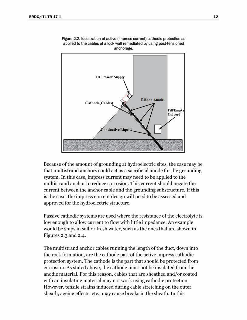
Cathodic protection can be implemented as an impressed current system (active) and a galvanic cathodic system (passive). For structures, such as long pipelines where passive galvanic cathodic protection is not adequate due to excessive resistance, an external direct current (D.C.) electrical power source is used to provide sufficient current. This type of cathodic protective system is referred to as an active cathodic protective system. Figure 2.2 shows an idealization of an active impress cathodic protection system application to a lock structure remediated by post-tensioned anchorage. Anodes are solid bars, metal ribbon, or anode wire of electrically conductive material.
ERDC/ITL TR-17-1 12
Figure 2.2. Idealization of active (impress current) cathodic protection as applied to the cables of a lock wall remediated by using post-tensioned
anchorage.
Because of the amount of grounding at hydroelectric sites, the case may be that multistrand anchors could act as a sacrificial anode for the grounding system. In this case, impress current may need to be applied to the multistrand anchor to reduce corrosion. This current should negate the current between the anchor cable and the grounding substructure. If this is the case, the impress current design will need to be assessed and approved for the hydroelectric structure.
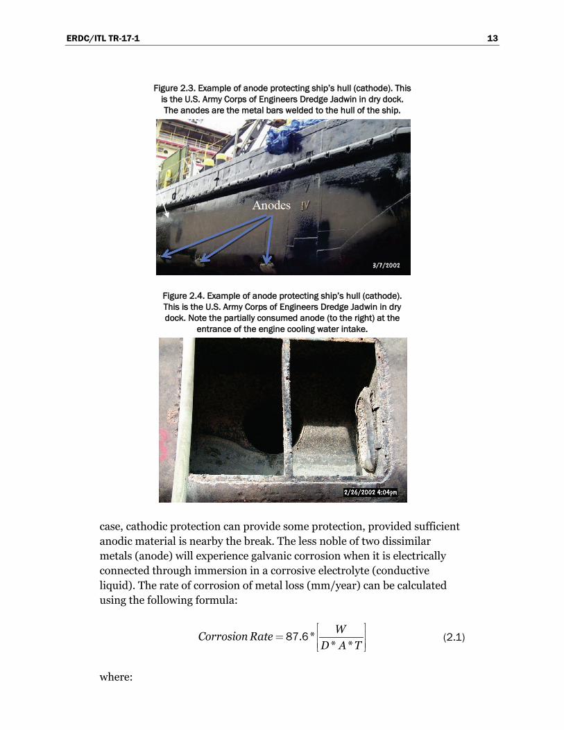
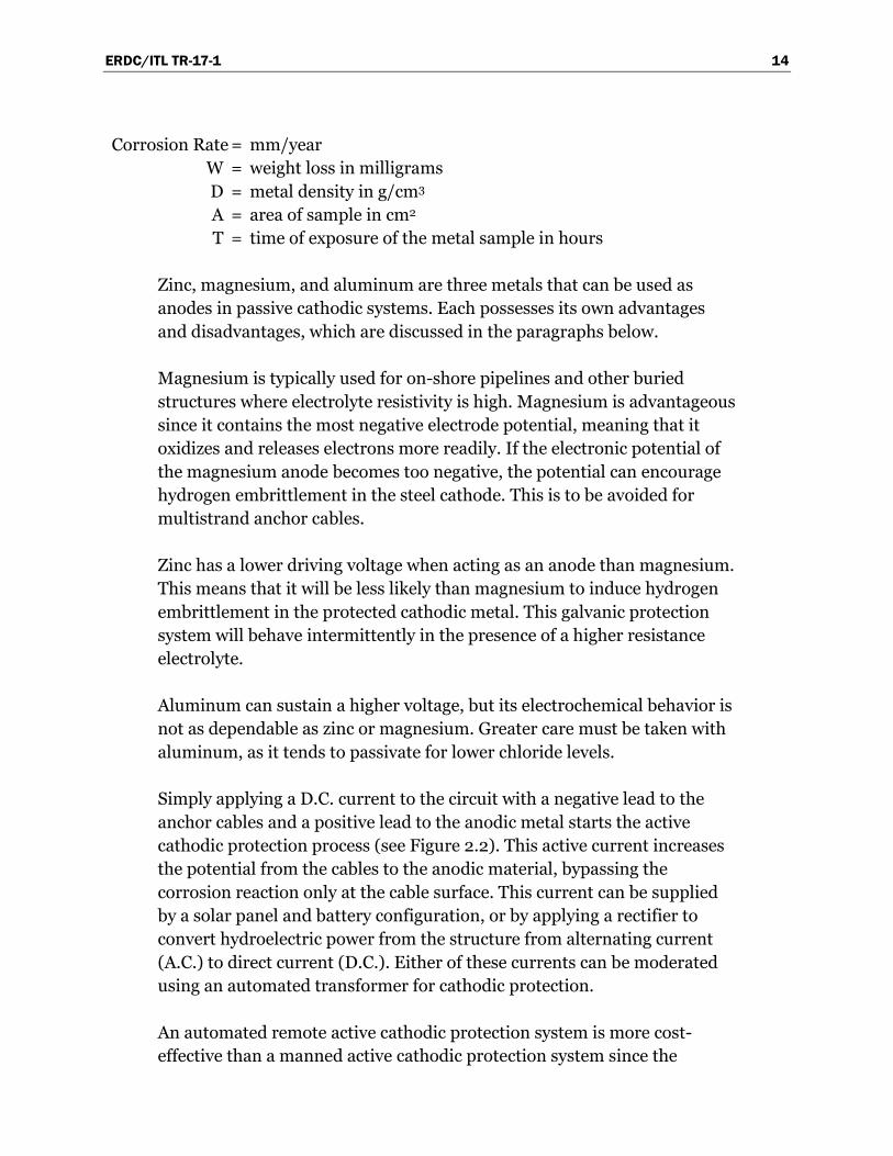
Passive cathodic systems are used where the resistance of the electrolyte is low enough to allow current to flow with little impedance. An example would be ships in salt or fresh water, such as the ones that are shown in Figures 2.3 and 2.4.
The multistrand anchor cables running the length of the duct, down into the rock formation, are the cathode part of the active impress cathodic protection system. The cathode is the part that should be protected from corrosion. As stated above, the cathode must not be insulated from the anodic material. For this reason, cables that are sheathed and/or coated with an insulating material may not work using cathodic protection. However, tensile strains induced during cable stretching on the outer sheath, ageing effects, etc., may cause breaks in the sheath. In this
ERDC/ITL TR-17-1 13
Figure 2.3. Example of anode protecting ship’s hull (cathode). This is the U.S. Army Corps of Engineers Dredge Jadwin in dry dock. The anodes are the metal bars welded to the hull of the ship.
Figure 2.4. Example of anode protecting ship’s hull (cathode). This is the U.S. Army Corps of Engineers Dredge Jadwin in dry dock. Note the partially consumed anode (to the right) at the
entrance of the engine cooling water intake.
case, cathodic protection can provide some protection, provided sufficient anodic material is nearby the break. The less noble of two dissimilar metals (anode) will experience galvanic corrosion when it is electrically connected through immersion in a corrosive electrolyte (conductive liquid). The rate of corrosion of metal loss (mm/year) can be calculated using the following formula:
. ** *WCorrosion Rate
D A T
87 6 (2.1)
where:
ERDC/ITL TR-17-1 14
Corrosion Rate = mm/year W = weight loss in milligrams D = metal density in g/cm3 A = area of sample in cm2 T = time of exposure of the metal sample in hours
Zinc, magnesium, and aluminum are three metals that can be used as anodes in passive cathodic systems. Each possesses its own advantages and disadvantages, which are discussed in the paragraphs below.
Magnesium is typically used for on-shore pipelines and other buried structures where electrolyte resistivity is high. Magnesium is advantageous since it contains the most negative electrode potential, meaning that it oxidizes and releases electrons more readily. If the electronic potential of the magnesium anode becomes too negative, the potential can encourage hydrogen embrittlement in the steel cathode. This is to be avoided for multistrand anchor cables.
Zinc has a lower driving voltage when acting as an anode than magnesium. This means that it will be less likely than magnesium to induce hydrogen embrittlement in the protected cathodic metal. This galvanic protection system will behave intermittently in the presence of a higher resistance electrolyte.
Aluminum can sustain a higher voltage, but its electrochemical behavior is not as dependable as zinc or magnesium. Greater care must be taken with aluminum, as it tends to passivate for lower chloride levels.
Simply applying a D.C. current to the circuit with a negative lead to the anchor cables and a positive lead to the anodic metal starts the active cathodic protection process (see Figure 2.2). This active current increases the potential from the cables to the anodic material, bypassing the corrosion reaction only at the cable surface. This current can be supplied by a solar panel and battery configuration, or by applying a rectifier to convert hydroelectric power from the structure from alternating current (A.C.) to direct current (D.C.). Either of these currents can be moderated using an automated transformer for cathodic protection.
An automated remote active cathodic protection system is more cost-effective than a manned active cathodic protection system since the

ERDC/ITL TR-17-1 15
automated system can be set up to notice and record changes in current draw, make decisions regarding the current draw, and take action based on pre-set parameters entered into the system’s programming. An automated system such as this may be accessed by Ethernet cable or satellite and be configured to be controlled with a cell phone.
This method also allows for continual monitoring of any changes in current to determine whether the system is working (Kean and Davies 1981). This anode, possibly a ribbon anode, would be placed near the cables without touching them and causing an electrical short. The external supply, possibly in conjunction with a rectifier, would be adjusted to increase the corrosion of anode and increase the protection of cables without significant production of hydrogen ions that could contribute to hydrogen embrittlement of the cables.
Hydrogen embrittlement is detrimental to a metal since hydrogen is absorbed into the metal. This would disrupt the crystalline structure of the metal that would then create fractures or cracks (Figure 2.5), which reduces the flexibility of the metal. High strength steels, such as those used in post tensioning, are especially susceptible to this effect. According to EM 1110-2-2704 (USACE 2004) citing NACE RP0169-2002, the system should be properly optimized by adjusting the rectifier until 90% of the potential falls within the range of polarized (cathodic) potential of between negative 850 mV and negative 1200 mV, or 100-mV polarization. The multiple micro-fractures caused by hydrogen embrittlement contained within a small region of the surface metal can be seen in Figure 2.5. This type of damage can come from over-voltage of an active cathodic protection system.
When measuring the voltage of an anode, a reference electrode is used for calibration purposes, which will always have the same electrical potential at any temperature. This reveals the electrical potential of the anode being tested in comparison with the stable reference electrode. Figure 2.6 describes how to measure potential difference with a reference electrode.

ERDC/ITL TR-17-1 16
Figure 2.5. Electron microscope view of hydrogen embrittlement (photo courtesy of NASA Corrosion
Technology Laboratory).
Figure 2.6. Depiction of potential measurement between anode and reference electrode (Chess and Gronvoid 1996).

ERDC/ITL TR-17-1 17
A copper sulfate reference electrode is commonly used for measuring the potentials of equipment under cathodic protection (Groysman 2010). This circuit can be used to determine how much corrosion is occurring as well as to determine the threat of hydrogen embrittlement. Redundant failsafe mechanisms should be provided in any attempt to use active cathodic protection on post tensioned steels (USACE 1999).
The passive cathodic protection system application shown in Figure 2.7 primarily differs from the Figure 2.2 active cathodic protection system by not having an external D.C. power supply and by not having wires connected directly to the anodes and cathodes. Once the protective current has been calculated, use Appendix A.1, Design Sequence for Cathodic Protection Systems flow chart to determine between galvanic or impressed current protective systems. If the conditions at the site are not clear, the choice is based on the current density required. At less than 1 mA/ft2, passive (i.e., galvanic) system is used; if the current density requirement is above 1 mA/ft2, then the active (i.e., impressed) current system should be used (see Chapter 2-3 USACE 2005).
Figure 2.7. Idealization of passive (sacrificial anode) cathodic protection as applied to the cables of a lock wall remediated by using post-tensioned
anchorage.
ERDC/ITL TR-17-1 18
Appendix B has equations and calculations required to determine the amount of anodic material needed for cathodic protection of an example anchor cable system with 100 ft anchor cables. Because Heslin et al. (2009) states that it is common belief that most anchors fail in the region close to the anchor head, calculations were also performed to determine the amount of anodic material required for protecting only the upper 10% (10 ft) of the anchor cables, to reduce costs. In the example problem, the protection required was at the threshold for the requirement of an active cathodic system.
2.1.1 Passive cathodic protection: Pro
• Capacity to significantly slow ongoing corrosion losses corrosion rate and system performance can be monitored
2.1.2 Passive cathodic protection: Con
• Requires placement of anode • Anode will need to be replaced on a schedule (passive?) • New system designs are needed
2.1.3 Active cathodic protection: Pro
• Based on the electrolytic process, moves corrosion to the anode • A D.C. current that is applied to the circuit establishes:
o Controlled rate of corrosion o Reduction of hydrogen embrittlement o Lower dependence on electrolyte resistance o Remote access (through internet interface)
• Easy access to D.C. power supply through rectification at hydro-electric facilities
• Can significantly slow corrosion rates
2.1.4 Active cathodic protection: Con
• Potential for hydrogen embrittlement • Needs new specialized systems for post-tension cables • Requires placement of anode • Anode will need to be replaced on a schedule • Requires installation and maintenance of D.C. power supply
ERDC/ITL TR-17-1 19
2.2 Cable drying
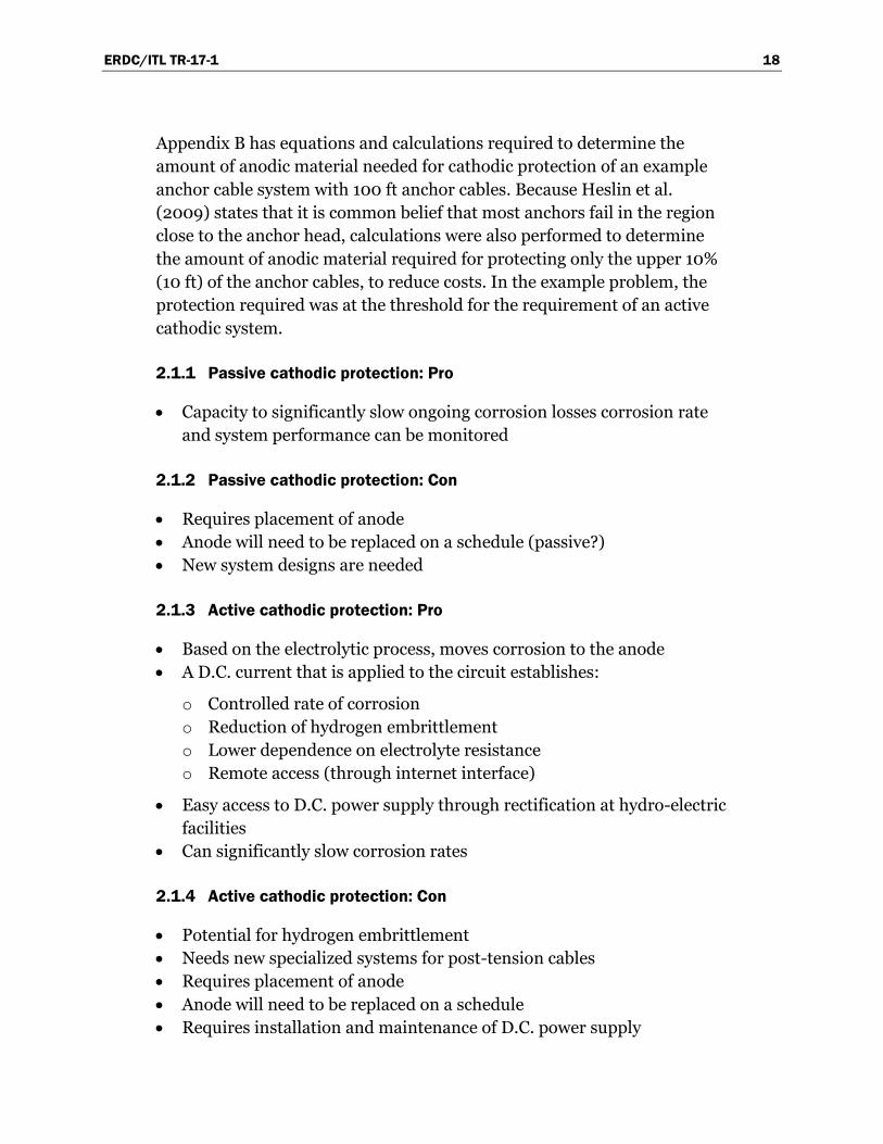
Moisture acts as an electrolyte (a medium by which electrons can flow) and is an essential environmental condition of the corrosion process. H. H. Uhlig (1948) researched the fact that if the local atmosphere has a relative humidity (RH) of more than 60%, corrosion increases, but as it lessens to 40% local atmosphere, it decreases to a very low (an almost nominal) rate, as can be seen in Figure 2.8.
Figure 2.8. Relationship between relative humidity and the rate of corrosion of iron in air with 0.01% sulfur dioxide (Uhlig 1948).
This moisture evaporates in the presence of moving gases. Means to remove moisture have been utilized to protect steel from corrosion (for example, in condensers at power plants during shutdown). The gasses used to remove the moisture must be inert, like nitrogen, so that they do not contribute to corrosion, as oxygen does. For the multistrand anchor system, the flow of nitrogen will also dry out both the water and the wet grout in a piped duct, where the nonporous plastic or metal sheath that forms the perimeter to the anchor cable system defines the duct pipe.
Figure 2.9 shows a possible cable-drying system that can maintain a positive pressure of nitrogen to a duct. Unfortunately, if several leaks exist in the duct pipe containing the cables, the gas pressure can dissipate before reaching the end of the cable. The gas is dissipated through three different mechanisms in the grout and/or mass concrete: the porosity of the material, cracks in the material, and voids that may have been
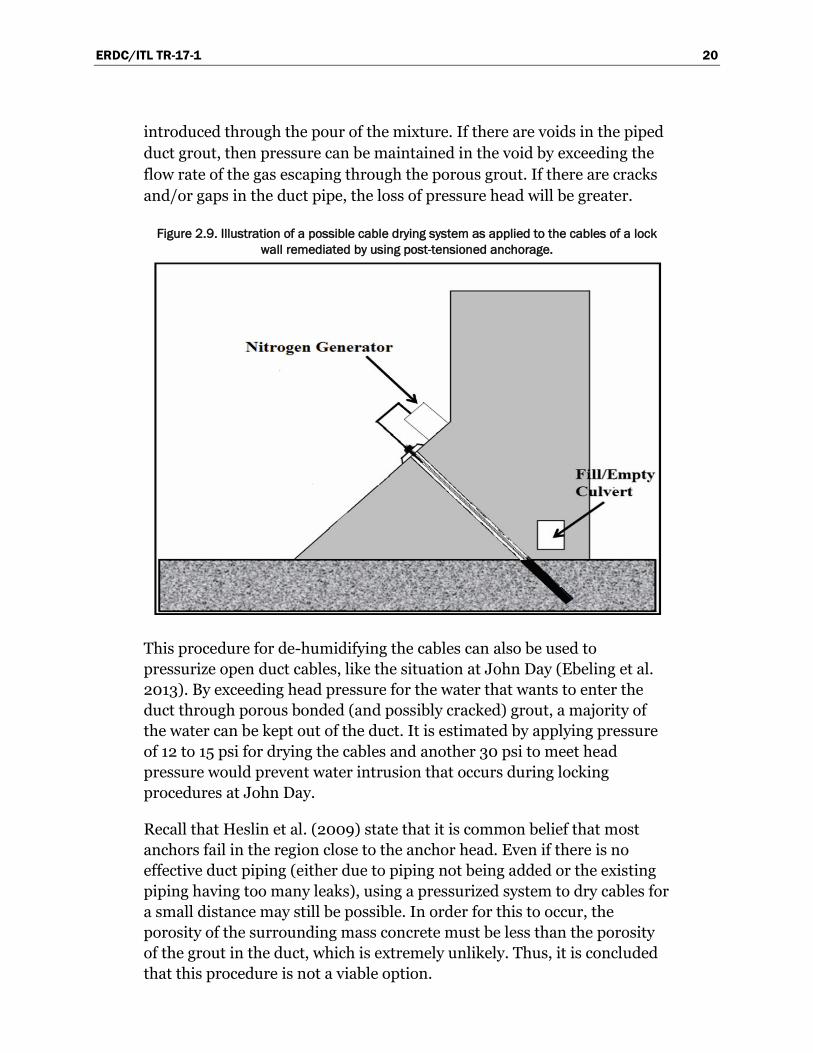
ERDC/ITL TR-17-1 20
introduced through the pour of the mixture. If there are voids in the piped duct grout, then pressure can be maintained in the void by exceeding the flow rate of the gas escaping through the porous grout. If there are cracks and/or gaps in the duct pipe, the loss of pressure head will be greater.
Figure 2.9. Illustration of a possible cable drying system as applied to the cables of a lock wall remediated by using post-tensioned anchorage.
This procedure for de-humidifying the cables can also be used to pressurize open duct cables, like the situation at John Day (Ebeling et al. 2013). By exceeding head pressure for the water that wants to enter the duct through porous bonded (and possibly cracked) grout, a majority of the water can be kept out of the duct. It is estimated by applying pressure of 12 to 15 psi for drying the cables and another 30 psi to meet head pressure would prevent water intrusion that occurs during locking procedures at John Day.
Recall that Heslin et al. (2009) state that it is common belief that most anchors fail in the region close to the anchor head. Even if there is no effective duct piping (either due to piping not being added or the existing piping having too many leaks), using a pressurized system to dry cables for a small distance may still be possible. In order for this to occur, the porosity of the surrounding mass concrete must be less than the porosity of the grout in the duct, which is extremely unlikely. Thus, it is concluded that this procedure is not a viable option.

ERDC/ITL TR-17-1 21
Keeping an inert gas in the duct also can make the environment favorable to the destruction or non-growth of microorganisms that enable deterioration of the cables. Microorganisms affect the environment of the duct containing the cables and the surface of the cables themselves where corrosion can result. They produce corrosion acids, ammonia, sulphides, dissolved oxygen, and salts. They can destroy the defensive layer on the steel cables (Gu and Mitchell 2006).
2.2.1 Cable drying: Pro
• Reduces moisture on the cables while removing oxygen for corrosion. • Pressurization reduces water intrusion for ducts with voids when
sufficient pressure is induced. • Can be used as a preparatory step before other mitigation techniques. • Inert gasses displacing oxygen around the cables would reduce
biological agents that can enable corrosion.
2.2.2 Cable drying: Con
• Requires a nonporous or low porosity boundary for the duct. If gaps exist in this boundary, the gas may escape before the entire cable has been dried.
• Additional machinery will be required and will have to be maintained. • For grouted systems, the pressure required to move water from around
the cables and out through the pores of the grout may be excessive. • For grouted cables, it may be difficult to provide enough pressure in
the system to provide protection all the way to the anchor end of the cable.
• Access vents could be unwieldy and may lead to a weakening of the lock wall structure.
• Limited applicability.
2.3 Re-grouting
Ideally, grout is used to surround the post-tensioned cable encasing it with a protective alkaline (passive) barrier. However, for multiple reasons such as inferior grout, inadequate grouting practices, or poor grout specification, many cables are not protected, and they corrode due to voids within the grout (Corven and Moreton 2013). Composed of cement, water, and addi-tives that achieve desired mechanical characteristics in the mixture, grouts are constituents with complex interactions. Calcium chloride or admixtures

ERDC/ITL TR-17-1 22
containing calcium chloride should never be used for post-tension construction as it causes corrosion according to Haas (2005). According to the Florida Department of Transportation (2002), grout is the primary protection against moisture and chloride penetration for post-tensioned systems. Because other types of cements need to be tested for their suit-ability, Portland cement is recommended for grouting tendons (Somerville 2002). Nash International, The Corrosion Society (2012), states that quality concrete slows the general penetration rate of both chloride ions and carbonation, and therefore is the first line of defense to extend the service life of anchorage system. The key to a successful grouting operation requires the correct grout mixture, proper mixing, and effective pumping into the tendon to provide immediate corrosion protection from moisture and chloride penetration for post-tensioned steel (Pielstick and Peterson 2002).
It is difficult to access the duct in order to gain access to voids without compromising the structural integrity. To inspect cable bundles, the duct opening should be opened carefully and upon inspection and/or repair, must be closed carefully (Somerville 2002). Another duct accessibility issue is that re-grouting in general should start at the low point in order to re-grout. Sometimes this is not possible, but when it is possible, it will be accomplished by boring a hole in the anchor head or diagonally to the bottom of the duct and inserting a tube all the way to the bottom of the duct, making it suitable for grout to flow upward. However, in many cases, not all voids around tendons are filled, with the result that voids will still exist. Inspection holes may be drilled around the cables and a bore scope investigation of the duct interior will increase the possibility of filling all voids in the duct. For a large number of voids, this procedure is impractical. It is recommended that this process be used for situations where large regions of the duct tube were left un-grouted. The re-grouting process is one that requires careful supervision and continual agitation of the mixture. It must be done in a timely manner. Also, the grout must be used within 30 min of mixing (Pielstick and Peterson 2002).
Re-grouting procedures must be determined based upon the geometrical characteristics (length, cross-section, volume, etc.) of pre-existing voids. According to Somerville (2002), vacuum-assisted grouting is recommended to measure the volume and the extent of the void, especially in larger areas. The first step is to reduce air pressure in the duct-to-sub atmospheric pressure (generally of about 80%), then reverse the airflow back into the duct. Based upon the recorded measurement of airflow, the

ERDC/ITL TR-17-1 23
appropriate alkaline materials are determined. The duct is then re-grouted by a suitable mortar. Quality control is an essential element in the grouting process and care must be used to follow manufacturer’s directions. The pressure with which the grout is pumped must be maintained at an adequate level, which is dependent upon the grout hose, vertical rise of the duct, and the length to be re-grouted. Supplemental grout or re-grouting has the potential of interactions with the existing grout of a different formulation. If the electrical resistance of one grout is different from an adjacent grout, there is an electrical potential difference. In other words, there would be an electrical current flowing from one grout to the other. Thus, galvanic corrosion will occur at the intersection of these two grouts on the post-tensioned cables.
Below is a list of the five main requirements that are used to determine a “suitable” mortar.
• A good flowing of grout mixture to completely fill the duct • A certain volume (X) of air is vacuumed from the duct; therefore, the
duct should hold the same volume (X) of grout • A specific amount of time for reabsorption of any bleed of water inside
the cable bundle duct • The adherence and strength of the grout • The grout’s resistance to freezing
Comparing the void volume to the actual volume of grout injected will determine if further grouting is needed. Grout will develop strength in excess of specified values if it is well designed with limited bleed and volume change (Somerville 2002).
It is recommended that a non-environment harming chelation-type rust remover be poured into the duct and possibly even poured down the king strand of the individual cables prior to the re-grouting process and left for at least two weeks to remove any rust. In addition, increasing the pH of existing grout would be advisable using “Increasing pH of electrolyte and/or grouted environment” as discussed in section 2.6.
2.3.1 Re-grouting: Pro
• Reduces free chlorides and gives moisture protection • Reestablishes oxide film • Enables filling of voids

ERDC/ITL TR-17-1 24
2.3.2 Re-grouting: Con
• This procedure is limited to anchorage with detectable locatable voids and/or to anchorage without grout in the unbounded section
• Must have ability to fill grout from the bottom of the cable • Rate of re-grouting before it sets • Different grout mixtures lead to galvanic response between existing
grout and new grout, possibly accelerating corrosion • Covers over existing corrosion
2.4 Rust remover
Many rust removers on the market attempt to remove existing rust from metals. Some of these rust removers are acids that dissolve the rust, which could significantly weaken iron and steel by causing hydrogen embrittlement (Gough et al. 2013; Johnson 1875), because the acid binds to the rust and leaves hydrogen ions. High strength steels are the most susceptible to hydrogen embrittlement along with titanium and aluminum alloys.
Some rust removers have neutral pH, avoiding the hydrogen embrittlement issues. Because they have neutral pH, they are also less hazardous for people to handle. They work mainly through selective chelation, a process in which a large synthetic molecule forms a bond with metals and holds them in solution. Since hazardous contaminants are not used, only the chelated iron requires disposal. There may be local, state, and federal guidelines for this chelated iron disposal.
Once the rust remover has completed de-rusting the cables, the solution may be left in the ducts as a barrier to corrosion, which must remain at a high enough concentration level to remain effective, or another mitigation strategy such as “Cable Drying,” as in section 2.2, could be implemented to keep the cables rust free.
Most, but not all, chelating agents bind to many different metals and contain EDTA (ethylenediaminetetraacetic), citric acid, glycolic acid, or their sodium salts. EDTA is biodegradable, but is considered to be a less-than-desirable candidate for access to ground water or soil. According to Gough et al. (2013) and Van Dijk-Looyard et al. (1990), since the ‘70s, there has been concern that EDTA could leach heavy metals back into the water column from sediment. This could lead to higher concentrations of
ERDC/ITL TR-17-1 25
cadmium, mercury, and lead in streams and ground water. Local, state, and federal guidelines for this chelated iron disposal may exist.
The application of chelation-type rust removers is a major limitation. Although these rust removers can be sprayed or pumped, submersion allows a thorough involvement of the rust remover with the rusted surface enabling the process where the rust remover chemical attaches to the rust itself and detaches from the metal that is to be cleaned. Grout and heavy grease must be removed prior to applying a rust remover, as it may prevent it from contacting the metal. For heavily corroded metals, rust removal may require that the metal soak for an extended period in the rust remover.
Diluted rust remover does not have the same effectiveness as undiluted rust remover. If enough water were somehow to mix with the rust remover, then the diluted rust remover would have to be pumped out and replaced with rust remover of sufficient concentration. This would ensure that the cables in the duct would not be in a corrosive environment. Even if ground water or some other dilatants did not get into the cable duct, the rust remover itself loses strength after time and would have to be replaced.
2.4.1 Rust remover: Pro
• Rust removers leave a thin protective surface. Some chelating rust remover removes existing iron oxides by separating iron from the oxides, but not iron from the steel. Some chelating rust removers have a neutral pH, and are neither acidic nor caustic.
• Some chelating rust removers are non-toxic and biodegradable. • Rust remover may be combined with other corrosion techniques. For
example, removing rust before chemical impregnation would ensure that corrosion would not continue to occur under the hardened chemical coating.
2.4.2 Rust remover: Con
• The thin protective surface left by the rust remover may not provide as much protection as an oxide film layer.
• EDTA removers need to address environmental concerns with the byproducts of chelation.
• Limited access, dependent on viscosity of rust remover and ability to get in contact with the cable.

ERDC/ITL TR-17-1 26
• If used as a stand-alone rust deterrent, this rust protection may need to be monitored and resupplied.
• Rust removal may have a detrimental effect on the corroded anchor cable strength. For example, a condition may be envisioned in which oxidized iron provides surface protection and helps to alleviate stress concentrations within a zone of pitting. Another condition that may be envisioned is corrosive material expanding to form a frictional “bonding” with the surrounding grout.
2.5 Re-greasing
Grease is a barrier to corrosion when applied to the post-tensioned cables. It displaces water and other components of corrosion away from the cables and has versatility in its formulation that can lead to different physical and chemical properties. For instance, viscosity at higher temperatures can be varied to allow for easier installation. Grease, made from petroleum and other natural elements as well as synthetic agents, is used in every industry.
Because grease is usually removed using caustic chemicals, heat, mechanical means, etc., removing old grease would require considerable effort. For the multistrand anchor situation, access to the grease is limited to a lift-off procedure at the anchor head (e.g., at John Day Lock) and the grease would need to be subjected to a heated caustic environment. When this occurs, the grease will be in a semi-liquid state and need to be pumped from its flow to the bottom of the anchor. The caustic environment, could lead to corrosion in the cables. Placing the new grease requires the same amount of access, which may limit the depth to which the newly formulated grease is placed. These observations lead the authors of this report to conclude that other than protecting cables and wedges at an exposed anchor head, this procedure would not be viable.
Grease would be selected with specific requirements, which would include the ability to resist cracking during extreme freezes, or endure unusually hot summers with no failure to adhere. The grease would have to endure constant water and moisture without any loss of any physical or chemical properties (note the deteriorated state of John Day Lock anchor head grease that has been exposed to water, microorganisms, and temperature extremes in Figures 2.10 through 2.12). It would have to be formulated to not only protect the cables from corrosive elements, but also to arrest the corrosion that was already on the cables. The protectant would have to be
ERDC/ITL TR-17-1 27
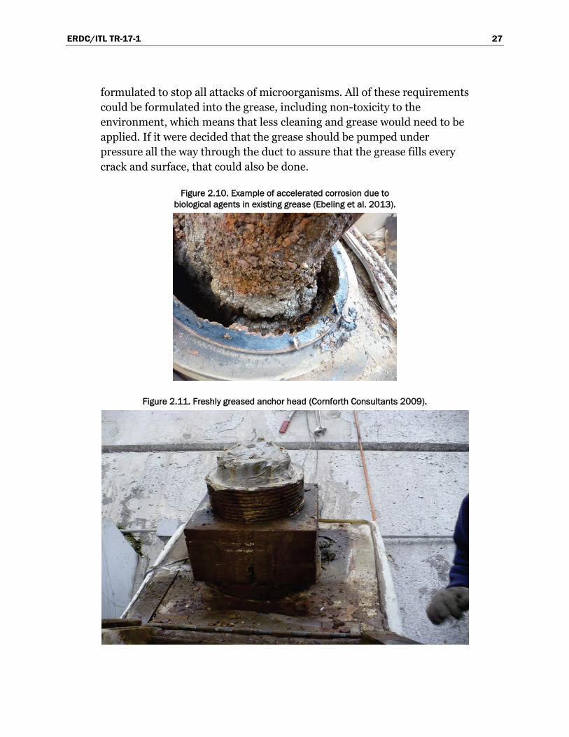
formulated to stop all attacks of microorganisms. All of these requirements could be formulated into the grease, including non-toxicity to the environment, which means that less cleaning and grease would need to be applied. If it were decided that the grease should be pumped under pressure all the way through the duct to assure that the grease fills every crack and surface, that could also be done.
Figure 2.10. Example of accelerated corrosion due to biological agents in existing grease (Ebeling et al. 2013).
Figure 2.11. Freshly greased anchor head (Cornforth Consultants 2009).
ERDC/ITL TR-17-1 28
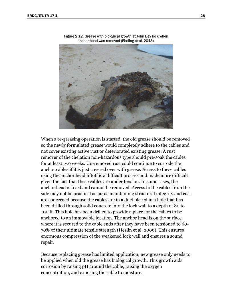
Figure 2.12. Grease with biological growth at John Day lock when anchor head was removed (Ebeling et al. 2013).
When a re-greasing operation is started, the old grease should be removed so the newly formulated grease would completely adhere to the cables and not cover existing active rust or deteriorated existing grease. A rust remover of the chelation non-hazardous type should pre-soak the cables for at least two weeks. Un-removed rust could continue to corrode the anchor cables if it is just covered over with grease. Access to these cables using the anchor head liftoff is a difficult process and made more difficult given the fact that these cables are under tension. In some cases, the anchor head is fixed and cannot be removed. Access to the cables from the side may not be practical as far as maintaining structural integrity and cost are concerned because the cables are in a duct placed in a hole that has been drilled through solid concrete into the lock wall to a depth of 80 to 100 ft. This hole has been drilled to provide a place for the cables to be anchored to an immovable location. The anchor head is on the surface where it is secured to the cable ends after they have been tensioned to 60-70% of their ultimate tensile strength (Heslin et al. 2009). This ensures enormous compression of the weakened lock wall and ensures a sound repair.
Because replacing grease has limited application, new grease only needs to be applied when old the grease has biological growth. This growth aids corrosion by raising pH around the cable, raising the oxygen concentration, and exposing the cable to moisture.
ERDC/ITL TR-17-1 29
2.5.1 Re-greasing: Pro
• Removal of old grease can remove biological agents that lower pH, raise temperatures, and produce oxygen – all of which raise the rate of corrosion.
• Provides a protective seal over cables, forcing damaging electrolytes (i.e., oxygenated water) away from the cable.
• New formulations resist biological micro-organisms that produce acidity and oxygen concentrations.
• Low maintenance.
2.5.2 Re-greasing: Con
• Limited access through the pile cap. Reaching the cable likely impossible.
• Previous grease must be removed, and the wires cleaned. Removal of the grease may call for harmful chemicals.
• Unless the cable is cleaned, grease will cover existing rust and allow pits to grow deeper.
2.6 Increase pH of free space and/or grout environment
Acidity has a significant effect on corrosion. Acidity and alkalinity are measured on the pH scale, which is a scale of 1 to 14, with 1 being the most acidic and 14 being the most alkaline (Figure 2.13). A number expressing the acidity or alkalinity of something on a logarithmic scale is called pH. Seven is neutral, lower values are more acidic, and higher values are more alkaline. The pH is equal to −log10 𝑐𝑐, where c is the hydrogen ion concentration in moles per liter. According to Baboian and Treseder (2002) citing Romanoff (1957), after an environment surpasses a pH of 7.5, acidic corrosion does not occur. This is not to say that corrosion does not occur, but that the acidity has little effect. Uhlig (1948) reveals that when the pH of an environment drops below 4 pH, the corrosion of steel greatly accelerates (Figure 2.14).

ERDC/ITL TR-17-1 30
Figure 2.13. Simple scale of alkaline-acid to pH number.
Figure 2.14. The effect of pH on corrosion (Uhlig 1948).
Carbonic acid production takes place when carbon dioxide is in the company of moisture. After contacting carbonic acid, grout and concrete lose some of their alkalinity, which in turn lowers the pH, thereby reducing the strength of the protective barrier to corrosion. The pH of cured cement is normally 12.5 to nearly 14, at the top of the pH scale. Guidance for grout mixtures states that the alkalinity of the grout mixture should be a value between 9 and 13.6 pH (Lee and Zielske 2014). However, the pH of the grout may be lowered by acidic fluids or by internal effects, such as carbonation of calcium hydroxide in cement, grout which can introduce carbolic acid (Shaker and Reddy 2009), or biological effects. At values of pH below 9, with enough chloride concentration and oxygen concentration in an electrolyte solution, steady corrosion will occur.
ERDC/ITL TR-17-1 31
Cement has a relatively high pH because it is a product of processed limestone. Because of the porosity of grout and mass concrete, the thought arose that grout pH may be raised by infusing the grout with a high alkalinity fluid mixture.
A method to increase the pH of the duct environment is to fill the free/empty space with a high alkaline liquid having a pH of 12 or greater. Then, the grout-covered cables should be soaked with a liquid that might penetrate some of the existing grout and increase the pH of that grout by means of an alkaline infusion and dispersal. If the duct is filled with alkaline liquid, the duct environment should have less possibility for corrosion. This could be monitored by simple litmus or electronic pH meter with a probe testing the liquid inside the duct.
This method of increasing pH by the introduction of high-alkaline liquids would require the addition of input valves for pumping in a low-viscosity lye solution under pressure. One issue that must be addressed with introducing a strong alkaline base into the system is the caustic effect of introducing the base into the surrounding environment through fluid flow. Extreme base solutions are used in industrial cleaners and clog removers, and can be quite damaging. While high alkalinity will protect the high-strength steel anchor cables, it can also cause damage to plants and animals.
If there were any cleaning-out of the ducts to do, accessibility to the length of the ducts would be needed. This would be difficult and costly to access the duct, which is totally encased in concrete from top to bottom, 80 to 100 feet long.
After consideration of the complexity of these details, this approach is deemed to be an unsafe means of providing corrosion protection.
2.6.1 Increased pH: Pro
• Raising the pH of the cable/grout environment reduces the corrosion rate by allowing the metal to rebuild an oxide film. This film provides a barrier to corrosion.
• Pumping in pH-altering chemicals will also affect the electrolytes already present about the cable.
• pH levels can be measured with simple pH tests to determine if the process is effective or needs to be repeated.
ERDC/ITL TR-17-1 32
2.6.2 Increased pH: Con
• Increasing the pH does not reduce the number of soluble chlorides in the grout, which can lead to corrosion in high-pH environments.
• The pH-increasing solution will not remove existing corrosion. • Depending on the viscosity of the pH-increasing solution, access may
be restricted. There may be no way to determine if pH protection has extended to the bottom of the cable.
• In low pH environments (i.e., low pH electrolytes flowing about the cables) or areas with high flow, this method may need to be continuously replenished.
• High alkaline solutions are used in commercial cleaners and can be dangerous to the environment.
2.7 Chemical impregnation though spaces between cable strands
Multistrand cables used in post-tensioned anchors on river locks usually have six strands of high-strength steel wound about a single strand (sometimes called the “king” strand). The required number of cables needed for the anchor’s specification are then guided through wedge holes in the anchor head and appropriately wedged in place after the required tension is applied (Ebeling et al. 2013).
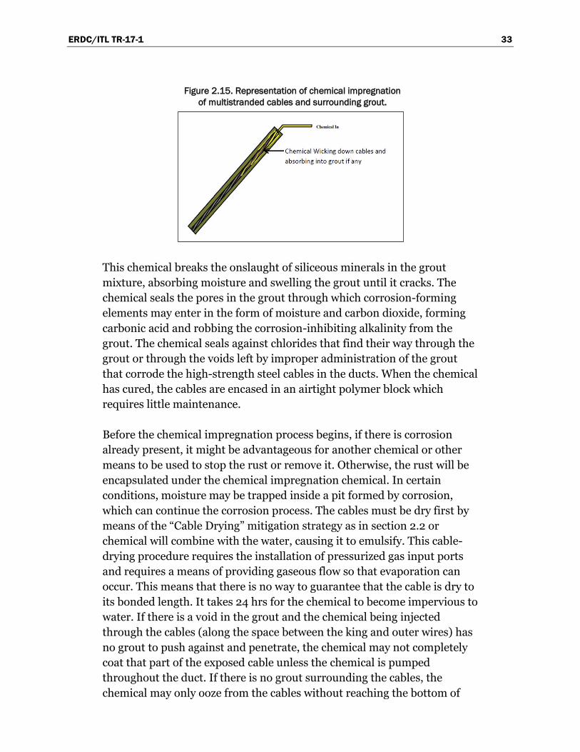
The chemical impregnation corrosion-mitigation strategy is one that does not require the releasing of the tension on the post-tensioned cables. The liquid is injected through the space around the center strand of the multistrand cable and wicks throughout the entire cable and into the grout surrounding the cable (Figure 2.15). It may also be injected into a cable that is bonded or has a coating or sheath around it. The chemical then dries in about 24 hrs to an almost impenetrable mechanical bond with the post-tensioned cables.
The chemical used in this corrosion mitigation technique has penetrating properties allowing it to wick evenly into the cured grout surrounding the cables. After the impregnation chemical has cured (typically within 24 hrs), it forms an impenetrable boundary that is relatively impervious with the exception of harsh chemicals (methylene chloride, etc.).
ERDC/ITL TR-17-1 33
Figure 2.15. Representation of chemical impregnation of multistranded cables and surrounding grout.
This chemical breaks the onslaught of siliceous minerals in the grout mixture, absorbing moisture and swelling the grout until it cracks. The chemical seals the pores in the grout through which corrosion-forming elements may enter in the form of moisture and carbon dioxide, forming carbonic acid and robbing the corrosion-inhibiting alkalinity from the grout. The chemical seals against chlorides that find their way through the grout or through the voids left by improper administration of the grout that corrode the high-strength steel cables in the ducts. When the chemical has cured, the cables are encased in an airtight polymer block which requires little maintenance.
Before the chemical impregnation process begins, if there is corrosion already present, it might be advantageous for another chemical or other means to be used to stop the rust or remove it. Otherwise, the rust will be encapsulated under the chemical impregnation chemical. In certain conditions, moisture may be trapped inside a pit formed by corrosion, which can continue the corrosion process. The cables must be dry first by means of the “Cable Drying” mitigation strategy as in section 2.2 or chemical will combine with the water, causing it to emulsify. This cable-drying procedure requires the installation of pressurized gas input ports and requires a means of providing gaseous flow so that evaporation can occur. This means that there is no way to guarantee that the cable is dry to its bonded length. It takes 24 hrs for the chemical to become impervious to water. If there is a void in the grout and the chemical being injected through the cables (along the space between the king and outer wires) has no grout to push against and penetrate, the chemical may not completely coat that part of the exposed cable unless the chemical is pumped throughout the duct. If there is no grout surrounding the cables, the chemical may only ooze from the cables without reaching the bottom of

ERDC/ITL TR-17-1 34
the cable or only travel around the center strand of the cable and protect the inside of the cable only, unless the entire duct is filled with the chemical. It may be possible, by measuring the rate that the chemical can be injected, to determine the effectiveness that the chemical impregnation will have.
2.7.1 Chemical impregnation: Pro
• Access is required only at the individual strand heads at the anchor head, which may stay in tension. Wicking action along the king wire carries the chemical down the cable.
• When the chemical sets, it forms a flexible polymer coating, preventing oxygenated water from reaching and corroding the cable.
• Wicks to fill pores in existing grout, limited by porosity and permeability of the grout and viscosity of the chemicals.
• Very low maintenance. When the system sets, moisture protection lasts a long time, unless harsh chemicals affect the polymer coating.
2.7.2 Chemical impregnation: Con
• Two-part chemical process takes 24 hours to set in a dry environment. The chemical must have wicked to the end of the cable and filled any voids next to the cable before setting, and not been washed away.
• Covers existing corrosion and mixes with existing water. The cable should be cleaned and dried (and kept dry) before chemical impregnation occurs. Water emulsifies the chemical polymer before it sets, reducing the effectiveness of the moisture seal.
• Unless voids are filled completely, there can be areas where the cable is not completely covered without wicking action. This method may be unsuitable for un-grouted cables by requiring an excess of chemicals.
• There may be environmental concerns.
2.8 Concrete healer/sealers
Concrete structures develop cracks from several causes (Figure 2.16). These include heating and cooling cycles, rain, freezing, thawing, the sun, earthquakes, and wind. Today, healer/sealers exist that, when mixed and used properly, provide healing and sealing in concrete because they penetrate the crack and do not wear off the surface. Cracks must be filled with healer/sealer to an extent that it prevents water infiltration (Soltesz 2010). If hydrostatic pressure is involved, a thicker epoxy type may be

ERDC/ITL TR-17-1 35
injected into the crack under pressure from the bottom up. For a crack in concrete to be considered healed, a minimum of 70% of the crack must be filled (Flax 2014). Before injecting the healer/sealer, the crack must be cleaned according to manufacturer’s instructions. It may be damp or dry, but not in standing water. Surface dirt and grease should be removed from the site of the crack. Mixing and/or injecting temperatures should be above 40 degrees Fahrenheit. The manufacturer may allow for the adding of aggregate to fill larger cracks. The healer/sealer is warranted for a year, but usually lasts a minimum of 4 to 5 years depending on stresses associated with the crack.
Figure 2.16. Products used in evaluation of healer/sealers study (Soltesz 2010).
Healer/sealers are formulated to have a low viscosity, allowing them to flow and wick to between 70-90% of the volume of the damage in the concrete. When the healer/sealers cure, they adhere to the sides of the crack in the concrete greater than the strength of the concrete itself. These healer/sealers also wick into the pores of grout or concrete that needs sealing. Wider cracks are not filled as well as thinner cracks unless higher-viscosity sealant is used. Also, while high viscosity resins leak less than low viscosity resins, leakage in and of itself could be of concern in filled applications (Soltesz 2010).
If a crack is at a high angle or vertical, the higher viscosity injectable sealant may need to be applied under pressure. The healer/sealer is flexible to the extent that shrinking and expanding of the concrete structure will not abate the healer/sealer’s ability to maintain its seal. In

ERDC/ITL TR-17-1 36
testing, when acid-soluble chloride was applied to an area in which healer/sealer had been applied, the chloride did not penetrate the barrier chloride at all (Flax 2014).
Healer/sealers, at their best, fill only 70-98% of the crack. They do not fill 100% of the crack. According to the Oregon Department of Transportation (DOT) in their State Research Report SRS 500-230, titled “Crack Sealer Fill Characteristics,” in June 2010, “Only one of the eleven crack sealers tested consistently met the 70% threshold” of minimum crack fill.
2.8.1 Concrete healer/sealers: Pro
• Serves to restrict water flow in concrete. • Are flexible when they set, providing protection as the structure moves. • Low maintenance. • Enhances other methods of cable corrosion mitigation.
2.8.2 Concrete healer/sealers: Con
• This procedure only fixes cracks that form voids along the cable. They are not a preventative measure at the cable.
• Covers only a percentage of the crack volume. Below a certain percentage, they are ineffective at water prevention.
• May require harder-to-install, higher viscosity healer/sealer for vertical cracks and/or environment.
2.9 Relief water wells and foundation drains
According to the U. S. Army Corps of Engineers in the Engineer Manual 1110-2-1914 (HQUSACE 1992), all water retention structures have seepage through their foundations and abutments. Relief wells divert and minimize seepages and pressure uplifts at these hydraulic structures. Seepage contributes to a corrosive environment in and around the structure including post-tensioned multistrand cable anchors. Relief wells also take care of other serious problems including water erosion of subsurface materials. These wells effectively preserve structural integrity of the locks and the success of their mission. Pumps can be installed on the wells to customize the foundation stabilization problems as well as corrosion problems associated with post-tension cable anchors and water seepage into the ducts (Forrester 2001).

ERDC/ITL TR-17-1 37
Relief wells may have differing designs and materials used to construct them, but they are all the same in that they are drilled holes in the ground with a plug in the bottom (Figure 2.17). The well shaft has a casing in it with holes in the side to let ground water in without letting the soil or other foundational materials get into the shaft and stop water flow. A riser pipe allows water to flow upward to the surface and a check valve prevents water from going back down the shaft. There is also a substantial cover over the wellhead to protect the well from animals, maintenance equipment, and vandals (HQUSACE 1992).
Figure 2.17. Illustration representing relief well (HQUSACE 1992).
If hydrostatic pressure is increased when the lock gates are opening or closing, wells can be strategically placed to relieve this pressure by diverting it through the wells. Any water source previously ejecting water through the ducts and up through the anchor cables could be redirected away from the anchor ducts with relief wells.
In the Corps of Engineers, new drainage fixtures will alter the flow regime and therefore alter the uplift distributions acting on the concrete structure. This will likely require a re-evaluation of stability of the mass concrete. The danger with water relief wells is that if too much water is removed from under the lock or its vicinity without replacing the uplift, the ground could possibly sink causing undesirable results.
The positioning of wells must be configured to consider accessibility for drilling and installation around the lock. Recognize that wells will likely

ERDC/ITL TR-17-1 38
redirect the groundwater flow at the region of the lock. As mentioned previously, the danger with water relief wells is that if a large change in the groundwater flow regime is made below the lock or its vicinity, the ground could possibly settle causing undesirable results. For this reason, the use of recharge wells is sometimes used or grouting of the lock foundation may be considered to reduce settlement. Maintenance on these wells is essential to their being useful in doing the job for which they were designed. Efficiency testing will show if a well is maintaining its original specifications. Cleaning the foundation drains underneath the lock will ensure that water drained from the structure has an open and unobstructed pathway. This will further alleviate corrosive environment elements including microorganisms that multiply (HQUSACE 1992). After water cycling through the ducts has stopped, the cable-drying technique mentioned in section 2.2 should be implemented permanently, bringing down the relative humidity reading in the ducts.
Due to high costs and difficulties with water flow and inconvenience with well placement, this method is presented only as an alternative. The authors do not feel that this method is viable.
2.9.1 Relief wells: Pro
• Drainage of water keeps cables dry. • Does not require access to cable wires (other than to guarantee drying). • Aids in the removal of biological corrosive agents. • Low maintenance. The well must only be monitored to make sure of
the amount of water removal, ensuring no blockages.
2.9.2 Relief wells: Con
• Limited cases of applicability • May require significant expense. Relief wells must be designed and
constructed. • Positioning may not be convenient to ensure drainage about the cables. • May affect the hydraulic conditions about the dam. Relief wells can
change the uplift pressures, backfill saturation, etc. • Does not deal with pre-existing corrosion.
ERDC/ITL TR-17-1 39
3 Summary and Conclusions
3.1 Overview: Corrosion in the multistrand anchor environment
Corrosion occurs to metal when elements of the environment react and cause an electrochemical reaction that binds oxygen to the metal. Factors that contribute to corrosion are
• Moisture (electrolyte), which MUST be present for corrosion to occur • Lower pH, which accelerates corrosion (especially below 4 pH) • Higher temperatures, which accelerate corrosion • Oxygen concentrated in the electrolyte • Chlorides, which lower resistivity of the electrolyte and act as a catalyst
causing the initiation of corrosion through oxide film removal
Pitting is the type of corrosion that is cited the most in technical literature. Pits can significantly reduce the capacity of post-tensioned cables by reducing the cross-section area and the inertial properties of the cross-section area of the cable, and its wires. Observed pit depths of over 1mm have been cited after a year has passed since corrosion initiation (Charng and Lansing 1982). The electro-chemical mechanics behind pitting corrosion are well described in Lee and Zielske (2014). For steel structures in a wet environment, corrosion occurs when the oxygen concentration in the water and the chloride concentration exceed a certain value. The chlorides act as a catalyst to bind oxygen to the iron atoms in the steel structure, forming iron oxide (or rust). This releases electrons which move away from the corrosion to another part of the steel structure. The low resistance of the water outside of the steel allows this electrical process to continue. The corroded material can expand from 2 to 6 times the original material size (Broomfield 1997).
The 1980-era John Day multistrand system configuration consists of thirty-seven 0.5 in. diameter post-tensioned cables using ASTM 416 high-strength steel which are used in a multistranded cable bundle for anchorage. The outside strand diameter for a cable is 0.165 in, and the center (king) strand diameter is 0.173 in. There are six outside strands and one center strand per cable. It is not uncommon for the cable bundle length to be 60-100 ft long and to be housed in a metal or plastic duct. Note that in some of these earlier post-tensioning systems, the upper
ERDC/ITL TR-17-1 40
section (10-20 ft) is packed in grease. Some may have grouting in the lower 75% of the duct; others may have no grout at all. Multistrand anchor cables are bound in place at the bonded (anchorage) zone of the cable at the base of the anchor. This area is held in place by grout, usually 20 to 40 ft in length, and transfers its tensile load into the rock foundation. The un-bonded zone has the cable free to stretch. The un-bonded zone can be surrounded by grout, but its cable is still free to stretch in that region. This grouted area of un-bonded cable can be produced by placing a protective sheath about the wires of the cable.2 The un-bonded zone is the primary region where corrosion is likely to occur.
Access to these cables at most Corps projects might be difficult, as these cables are set under tension requiring that the anchor head should not be removed. Access to the cables from the side may not be practical as far as maintaining structural integrity and cost are concerned. This is because the cables are in a duct that has been placed in a hole that has been cored through solid concrete into the lock wall to depths approximately 80 to 100 ft. This cored hole provides a place for the cables to be anchored to an immovable location, i.e., the anchor bond zone, in which load transfer into a rock foundation occurs. At John Day, the anchor head is located on the lock wall’s surface, where it is secured to the cable ends after they have been tensioned to 60-70% of their maximum ultimate tensile strength.
3.2 Summary: Corrosion mitigation techniques explored
This technical report has provided an abbreviated history of the development of post-tensioned cable anchors and described the corrosion problems that can occur in post-tensioned cable anchors, and may exist in older installations. This initial investigation provides a list of mitigation strategies and discusses the possibility that these strategies can be successfully implemented for the Corps hydraulic structures. The corrosion initiating problems noted so far are:
2 By modern PTI standards, the strands in unbounded applications are coated with corrosion-inhibiting
grease and encased in an extruded plastic (protective) sheath that acts to prevent the cables from bonding with the surrounding (corrosion protecting) cementitious grout. In contrast, bonded cables are stretched prior to grouting of the duct (with the cementitious grout again providing corrosion protection to these bonded cables) but without a bond-break feature. It has been argued that the ability of unbonded cables to move freely relative to the surrounding cementitious grout is an advantage over bonded cables for it eliminates tensile stress transfer to the hardened grout and surrounding mass concrete should the cables elongate under lateral loading (e.g., during lock filling and emptying cycles) and thereby reduce the risk for concrete cracking.

ERDC/ITL TR-17-1 41
• Water in multistrand anchor ducts, either immersed or as moisture • Oxygen concentrated in the water • Carbon dioxide and moisture inside the duct that can make carbonic
acid, lowering pH • Unbound chlorides in grout • Contamination of grease on cables • Voids in some grouted ducts due to bubbles in the grout or
complications in the grouting process • Cracks in some of the lock walls
The following techniques were researched:
1. Cathodic protection 2. Cable drying 3. Re-grouting 4. Rust removal 5. Re-greasing 6. Increase pH of free space or grout environment 7. Chemical impregnation 8. Concrete healers and sealers 9. Relief water wells
Each technique was examined with regard to the multistrand environment to determine its benefits and risks/challenges associated with its application. These pros and cons were documented, highlighting the protective characteristics and ease of use.
3.3 Conclusions
There are a variety of practices to mitigate corrosion. We gave a preliminary investigation of the feasibility and capabilities of these techniques in the multistrand environment. We reviewed corrosion mitigation strategies, listing the pros and cons of each. Nine methods or techniques have been briefly presented that have the ability to decrease or stop the corrosion rate of post-tensioned cable anchors in various stages of deterioration on locks. Each of the techniques could be accomplished without de-stressing the cables by drilling or cutting access holes that do not interfere structurally with the lock wall to any unsafe level, with some being easier to implement than others. All but two seriously impede the rate of pitting corrosion if implemented successfully. These are cathodic protection, cable drying, re-grouting, rust remover, re-greasing, increase

ERDC/ITL TR-17-1 42
pH, and chemical impregnation. The two exceptions are relief wells and healer/sealers, which are pre-repair techniques to alleviate incoming water to the ducts through cracks in the lock wall itself. Four of the repair techniques, cable drying, increase the pH, rust remover, and chemical impregnation, are easy to implement, and if implemented correctly, could reduce the corrosion rate and prevent reoccurrence.
In some cases, environmental concerns are raised which may eliminate these methods from consideration. Chelating rust removers, while possibly biodegradable and non-caustic, can have byproducts that can introduce contaminants into the source of moisture affecting multistrand anchor cables or concrete. This source of moisture may be groundwater or the lock chamber water. Increasing the pH by introducing a high pH solution can be extremely caustic and may have a deleterious effect on surrounding water. Removing grease for re-greasing may also require caustic chemicals.
Some of these methods can have an effect on the multistrand anchor cables themselves. In order to remove existing grease for cable re-greasing, caustic chemicals and steam may be required. While caustic chemicals may have a limited effect on the metal, introducing steam may increase existing corrosion and introduce new corrosion in the cables before the new grease is installed. Expanding rust, which has a greater volume than the metal in the cable, can serve as a frictional bonding zone with surrounding cement. An argument can be made that removing this supporting rust can introduce more stress at pits that already exist in the cables. Cathodic protection must be monitored to reduce the likelihood of hydrogen embrittlement in the high-strength steel cables.
Some methods require service and maintenance of the equipment. Cable drying, active cathodic protection, rust removers, and active pH balancing will require regular maintenance schedules.
Relief wells are a very expensive solution and may be more costly than replacing the multistrand anchor cables. Healer/sealers are an indirect solution applied to the lock walls for more reasons than for multistrand anchor corrosion mitigation alone.
The most promising of these mitigation methods would be the application of chemical impregnation for coating cables to keep moisture out (which is
ERDC/ITL TR-17-1 43
along the lines of PTI standards) and active cathodic protection, which has been successfully applied in other applications. The location of the anchors will determine which of these many methods is applicable.
Cost versus service life of repair, difficulty to repair and safety considerations will determine which repair and mitigation technique should be chosen to confront the corrosion issue of post-tensioned cable anchors.
ERDC/ITL TR-17-1 44
References Baboian, R., and R. S. Treseder. 2002. NACE corrosion engineer's handbook. Third
Edition. Houston, Texas: NACE International.
Bertolini, L., B. Elsener, P. Pedeferri, E. Redaelli, and B. R. Polder. 2013. Corrosion of steel in concrete: prevention, diagnosis, repair. Weinheim, Germany: Wiley, John & Sons, Incorporated.
Bloomstine, Matthew L. 2013. Main Cable Corrosion Protection by Dehumidification-Experience, Optimization and New Development. http://www.dsbrown.com/Resources/Bridges/cableguard/Main%20Cable%20Corrosion%20Protection%20M%20L%20Bloomstine.pdf.
Broomfield, J. P. 1997. Corrosion of steel in concrete, understanding, investigation and repair. Boca Raton: Chapman and Hall.
Bruce, Donald A., and J. S. Wolfhope. 2006. Rock anchors for dams: national research project: the(semi) final results of the phase 1 study. Boston, MA: ASDSO Dam Safety.
Bushman, J. B. 2001. Galvanic anode cathodic protection system design. Medina, Ohio: Bushman & Associated, Inc.
Charng, T., and F. Lansing. 1982. Review of corrosion causes and corrosion control in a technical facility. TDA Progress Report 42-69. ipnpr.jpl.nasa.gov/progress_report/42-69/69O.PDF.
Chess, P., and F. Gronvold. 1996. Corrosion investigation a guide to half cell mapping. London: Thomas Telford Ltd.
Corrosion Doctors. 2014. Water resistivity measurement. n.d. http://corrosion-doctors.org/Corrosion-Kinetics/Ohmic-drop-water.htm.
Corrosionist The Website of Corrosion Protection and Corrosion Prevention. n.d. 2014. http://www.corrosionist.com/corrosion_rate_conversion.htm.
Corven, J., and A. Moreton. 2013. Post-tensioning tendon installation and grouting manual. FHWA-NHI-13-026. Federal Highway Administration: U.S. Department of Transportation.
Ebeling, R. M., R. C. Patev, and R. L. Mosher. 1996. Case histories of earth pressure-induced cracking of locks. Technical Report No. ITL-96-9. Vicksburg MS: Waterways Experiment Station.
Ebeling, R. M., R. W. Haskins, D. H. Scofield, J. E. Hite, and R. W. Strom. 2012. Post-tensioned multistrand anchorage capacity deterioration due to corrosion: John Day Lock Project. ERDC/CHL CHETN-IX-28. Vicksburg, MS: U. S. Army Engineer Research and Development Center.
ERDC/ITL TR-17-1 45
Ebeling, R. M., R. W. Strom, J. E. Hite, R. W. Haskins, and J. A. Evans. 2013. Assessing corrosion damage and corrosion progression in multistrand anchor systems in use at Corps projects. ERDC TR-13-3. Vicksburg, MS: U. S Army Engineer Research and Development Center.
Flax, D. 2014. The new generation of crack healer/sealers. Concrete repair bulletin, ICRI.
Forrester, Kevin. 2001. Subsurface drainage for slope stabilization. Reston, VA: American Society of Civil Engineers.
Gough, T., M. R. Giles, and N. J. Dixon. 2013. Use of ethylenediamine disuccinic acid in metal surface treatment. Transactions of the 286 Institute of Metal Finishing 91(6): pp. 286-289.
Groysman, Alec. 2010. Corrosion for Everybody. Springer Dordrecht Heidelberg London New York: Springer Science+Business Media B.V.
Gu, Ji-Dong, and R. Mitchell. 2006. Biodeterioration. Chapter 3.9 in The Prokaryotes 1: 864-903, Third ed. Springer Link. http://link.springer.com/referenceworkentry/10.1007/0-387-30741-9_27.
Guyer, J. Paul. 2015. An Introduction to Cathodic Protection. CreateSpace Independent Publishing Platform: An Amazon Company.
Haas, F. 2005. How to estimate the cost of a post-tension slab-on-grade. Boston, MA: American Society of Professional Estimators (ASPE).
Headquarters, U.S. Army Corps of Engineers (HQUSACE). 1954. Hydroelectric power plants electrical design. Engineer Manual 1110-2-3006. Washington, D.C.: U.S. Army Corps of Engineers.
Headquarters, U.S. Army Corps of Engineers (HQUSACE). 1985. Electrical Design, Cathodic Protection. Technical Manual 5-811-7. Army Publications. http://armypubs.army.mil/eng/DR_pubs/dr_a/pdf/tm5_811_7.pdf
Headquarters, U.S. Army Corps of Engineers (HQUSACE). 1992. Design, Construction, and maintence of relief wells. Engineer Manual 1110-2-1914. Washington, D.C.: Department of the Army.
Headquarters, U.S. Army Corps of Engineers (HQUSACE). 1994. Hydroelectric power plants electrical design. Engineer Manual 1110-2-3006. Washington, D.C.: U.S. Army Corps of Engineers.
Headquarters, U.S. Army Corps of Engineers (HQUSACE). 1995. Evalulation and repair of concrete structures. Engineer Manual 1110-2-2002. Washington, D.C.: Department of the Army.
Headquarters, U.S. Army Corps of Engineers (HQUSACE). 1999. Operation and maintenance of public works cathodic protection systems. Technical Bulletin 420-49-29, Public Works Technical Bulletin, Alexandria, VA: Department of the Army, Section 2-10, page 2-15.
ERDC/ITL TR-17-1 46
Headquarters, U.S. Army Corps of Engineers (HQUSACE). 2004. Cathodic protection systems for civil works structures. Engineer Manual 1110-2-2704. Washington, D.C.: U.S. Army Corps of Engineers.
Headquarters, U.S. Army Corps of Engineers (HQUSACE). 2005. Electrical Design, Cathodic Protection. Unified Facilities Criteria, UFC 3-570-02A, Supersedes Technical Manual 5-811-7. Army Publications. https://www.wbdg.org/ccb/DOD/UFC/ufc_3_570_02a.pdf.
Heslin, G., D. A. Bruce, G. S. Littlejohn, and T. Westover. 2009. Performance of aging post-tensioned rock anchors in dams. In Proceeding, ASDSO Northeast Regional Conference, 14-16 June. State College, PA: Cornforth Consultants, Inc.
Hopwood, T., and J. H. Havens. 1984. Corrosion of cable suspension bridges. Research report. UKTRP-84-14, Kentucky Transportation Research Program, College of Engineering, University of Kentucky, Lexington, KY: State of Kentucky and the FHWD, http://www.ktc.uky.edu/files/2012/09/1984-Corrosion-of-Cable-Suspension-Bridges-UKTRP-84-14.pdf.
Johnson, W. H. 1875. On some remarkable changes produced in iron and steel by the action of hydrogen and acids. In Proceedings of the Royal Society of London. 23(158): 168-179.
Kean, R. L. Eur Ing, and K. G. Davies. Cathodic Protection. 1981. http://www.npl.co.uk/upload/pdf/cathodic_protection.pdf.
Lee, S-K., and J. Zielske. 2014. An FHWA special study: post-tensioning tendon grout chloride thresholds. Federal Highway Administration Research and Technology, Report No. FHWA-HRT-14-039, McLean, VA: Federal Highway Administration.
Mahmound, Khaled M. 2011. Modern Techniques in Bridge Engineering: In Proceedings of 6th New York city bridge conference, 25-26 July, 1st edition. CRC Press: Taylor & Francis Group. http://books.google.com/books?id=HeAifA7BiCMC&pg=PA40&dq=Dehumidification+is+based+on+the+fact+that+steel+does+not+corrode+when+the+relative+humidity+(RH)+of+the+lo-cal+atmosphere+is+below+40%25.+This+was+proven+by+research+at+MIT+Corrosion+Laboratory+lea.
McGlothlin, S. and M. Jago. 2003. Combating Corrosion. CleanTech for cleaning process improvement. http://www.orisonmarketing.com/documents/er/CleanTech2.pdf.
NACE International, The Corrosion Society. November 2012. Corrosion control plan for bridges. Houston, TX: NACE International.
NYSDOT Office of Operations. 2014. TSP2 Transportation System Preservation Technical Service Program. TSP2. https://www.tsp2.org/library-tsp2/uploads/106/Cathodic_Protection_Systems_Use_of_Sacrificial_or_Galvanic_Anodes_on_In-Service_Bridges.pdf.
Permanent International Association of Navigation Congresses, International Commission for the Study of Locks. 1985. Final Report of the International Commission for the Study of Locks. Brussels: PIANC, n.d.

ERDC/ITL TR-17-1 47
Pielstick, B. and G. Peterson. 2002. Grouting of bridge post-tensioning tendons training manual. Tallahassee, FL: Florida Department of Transportation.
Prestressed Concrete Institute (PCI). 1974. Tentative Recommendations for Prestressed Rock and Soil Anchors, Phoenix: Prestressed Concrete Institute (PCI).
Post-Tensioning Institute. n.d. http://www.post-tensioning.org/ (accessed August 5th, 2014).
Post Tensioning Institute (PTI). 2004. Recommendations for Prestressed Rock and Soil Anchors, Phoenix: Post Tensioning Institute (PTI).
Post Tensioning Institute (PTI). 1996. Recommendations for Prestressed Rock and Soil Anchors, Phoenix: Post Tensioning Institute (PTI).
Post Tensioning Institute (PTI). 1986. Recommendations for Prestressed Rock and Soil Anchors, Phoenix: Post Tensioning Institute (PTI).
Post Tensioning Institute (PTI). 1980. Recommendations for Prestressed Rock and Soil Anchors, Phoenix: Post Tensioning Institute (PTI).
Radiometer Analytical. 2003. pH theory and practice. Company, Educational, France: Radiometer Analytical SAS.
Revie, R. W. and H. H. Uhlig. 2008. Corrosion and Corrosion Control. 4th Edition. Hoboken, New Jersey: John Wiley & Sons.
Romanoff, M. 1957. Underground Corrosion. NIST.
Sears, F. W., M. W. Zemansky, and H. D. Young. 1990. College Physics 7th Edition. Reading, MA: Addison-Wesley.
Shaker, R. M., and Ramesh R. Prof. Reddy. 2009. Re-alkalization of carbonated reinforced cement concrete members. http://www.nbmcw.com/concrete/934-re-alkalization-of-carbonated-reinforced-cement-concrete-members.html.
Soletesz, S. 2010. Crack sealer fill characteristics: state research SRS 500-230. Salem, OR: Oregon Department of Transportation.
Somerville, G. 2002. Grouting of post-tensioning tendons. Subingen, Switzerland: VSL Internanational Ltd.
Uhlig, H.H. 1948. The Corrosion Handbook. Somerset, NJ: Wiley and Sons.
U.S. Department of Energy. 1993. DOE Fundamentals Handbook: Chemistry. Vol. 1 of 2. DOE-HDBK-1015/1-93. Washington, D.C.: U.S. Department of Energy.
Van Dijk-Looyaard, A. M., A. C. DeGroot, P.J. C. M. Janssen, and E. A. Wondergem. 1990. EDTA in drink-en oppervlaktewater. H2O. 682–687. National Institute for Public Health and the Environment: Ministry of Health, Wealfare and Sport.
ERDC/ITL TR-17-1 48
Appendix A
The passive cathodic protection system application shown in Figure 2.7 primarily differs from the Figure 2.2 active cathodic protection system by not having an external D.C. power supply and by not having wires connected directly to the anodes and cathodes. Once the protective current has been calculated, use Appendix A.1, Design Sequence for Cathodic Protection Systems flow chart to determine between galvanic or impressed current protective systems. If the conditions at the site are not clear, the choice is based on the current density required. At less than 1 mA/ft2, passive (i.e., galvanic) system is used. If the current density requirement is above 1 mA/ft2, then the active (i.e., impressed) current system should be used (see Chapter 2-3 HQUSACE 2005).
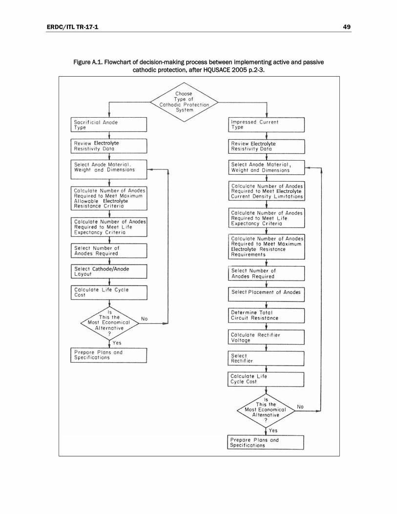
ERDC/ITL TR-17-1 49
Figure A.1. Flowchart of decision-making process between implementing active and passive cathodic protection, after HQUSACE 2005 p.2-3.

ERDC/ITL TR-17-1 50
Appendix B
As instructed in the Unified Facilities Criteria 3-570-02A (UFC 2005), certain information needs to be collected before any cathodic protection system can be implemented. First, the surface area of the item to be protected should be calculated. Using the John Day Lock on the Columbia River as the example, 0.5-in.-diameter post-tensioning cables using ASTM 416 high-strength steel are used in a multistrand cable bundle for anchorage. The outside strand wire diameter for a cable is 0.165 in. and the center (king) strand wire diameter is 0.173 in. There are six outside strand wires and one center strand wire per cable. The cable length is 100 ft. The surface area (SA) of one strand wire can be computed using the equation
* πr πr l SAof acylinder 22 2 (B.1)
Substituting the numbers for an outside strand wire gives:
2π0.08252 in. + 2π0.0825 in. *1200 in. = SA of outside strand wire
For a single cable, the total surface area of the outside strand wires are given by
* SA of outside strand wire SA of outside strand wires per cable6 (B.2)
And for the entire anchor
*
Aof outside strand wires per cableSAof total outside strand wires inthe cablebundle
3737
(B.3)
The values for the inside strand wire can be computed in the same manner as an outside strand wire
2π0.08652 in. + 2π0.0865 in. *1200 in. = SA of inside strand wire
S
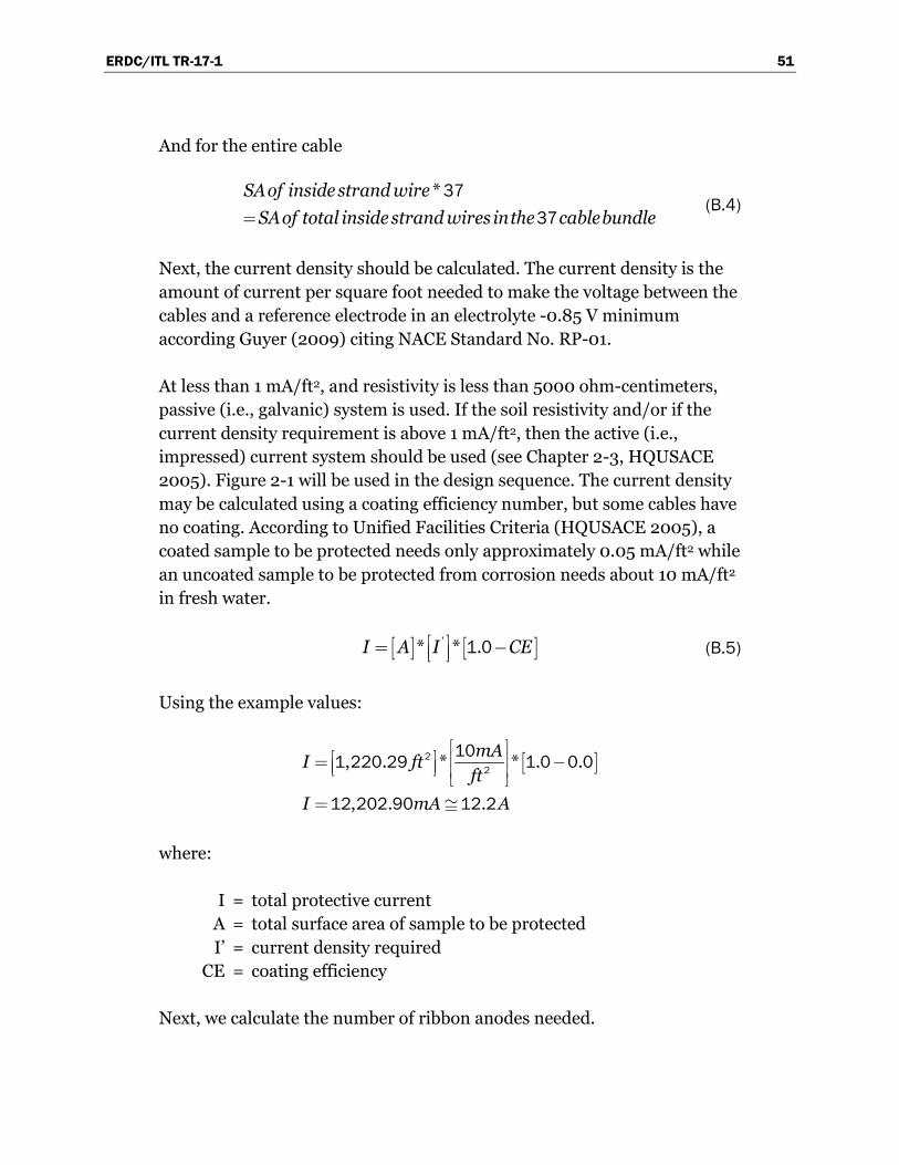
ERDC/ITL TR-17-1 51
And for the entire cable
*
SAof inside strand wire
SAof total inside strand wires inthe cablebundle37
37 (B.4)
Next, the current density should be calculated. The current density is the amount of current per square foot needed to make the voltage between the cables and a reference electrode in an electrolyte -0.85 V minimum according Guyer (2009) citing NACE Standard No. RP-01.
At less than 1 mA/ft2, and resistivity is less than 5000 ohm-centimeters, passive (i.e., galvanic) system is used. If the soil resistivity and/or if the current density requirement is above 1 mA/ft2, then the active (i.e., impressed) current system should be used (see Chapter 2-3, HQUSACE 2005). Figure 2-1 will be used in the design sequence. The current density may be calculated using a coating efficiency number, but some cables have no coating. According to Unified Facilities Criteria (HQUSACE 2005), a coated sample to be protected needs only approximately 0.05 mA/ft2 while an uncoated sample to be protected from corrosion needs about 10 mA/ft2 in fresh water.
'* * .I A I CE 1 0 (B.5)
Using the example values:
, . * * . .
, . .
mAI ftft
I mA A
22
101 220 29 1 0 0 0
12 202 90 12 2
where:
I = total protective current A = total surface area of sample to be protected I’ = current density required CE = coating efficiency
Next, we calculate the number of ribbon anodes needed.

ERDC/ITL TR-17-1 52
The yearly consumption rate of a zinc ribbon anode with dimensions of 3/4 in. x 3/8 in. x 100 ft is
Consumption rate * total protective current
hrsnumberyear
numberamphrslbs
(B.6)
Using the example values:
* . amps . * . amps .
hrslbs lbsyear
amphrs year yearlbs
876012 20 287 55 12 20 287 55
380
For a 10-year protective service life of this passive cathodic zinc ribbon anode system for one duct, one would need:
. *lbs years
year287 55 10
or 2875.00 lbs of zinc ribbon anodes.
For the yearly consumption rate of magnesium ribbon anode with dimensions of 3/4 in., 3/8 in., 100 ft, Equation B.6 can be used with the following results
* . amps . * . amps .
hrslbs lbsyear
amp hrs amp year yearlbs
876012 20 17 52 12 20 213 74
500
For a 10-year protective service life of this passive cathodic magnesium ribbon anode system for one duct, one would need:
. *lbs years
year213 74 10
or 2,137.44 lbs of magnesium ribbon anodes.

ERDC/ITL TR-17-1 53
After calculating a required 2875.00 lbs of zinc needed for sufficient passive cathodic protection or a required 2137.44 lbs of magnesium needed for sufficient passive cathodic protection, it is apparent that it would be impractical to insert this amount of anode material into a duct with an inside diameter of 8 in. that is already occupied by a bundle of 37 half-inch cables. This cathodic protection system would be best attempted in the construction of new post-tensioned strand cable anchors. Even if the resistivity of the electrolyte were changed to reflect a calculated drop in needed anode material, this would be negligible when compared to hundreds of pounds of anode material still needed to be inserted into the already full duct.
As for the consideration of active cathodic protection, a 0.62 in. (1.5 mm) mixed metal-oxide wire anode is desirable for active cathodic with ground water applications. This anode would be flexible enough that it could possibly be snaked through a hole in the anchor head itself with the anode itself inside a perforated or slotted plastic tube so that the anode would not electrically short to either the cables or the side of the conductive duct (where applicable). In addition, the cable bundle should be surrounded by several anodes to ensure protective coverage of the outside of the cables due to the current following the path of least resistance. The inside of the cable bundle would not be assured of being protected for the same reason.
In addition to the pounds of anode material inside the duct (sometimes a distance of 100 ft), the anodes must be separated from the cables and inside duct wall to prevent a dead short between the anode/cables/duct. This would result in dangerous heat buildup for power sources and power lines or a stoppage of rectifier supplied power by means of a blown fuse in the rectifier. If there is a battery for the power supply instead of a rectifier, to touch any part of the anode to the cables is basically touching the two leads of the battery together resulting in battery destruction unless contact is broken between anode and cables.
As stated by (Heslin et al. 2009), most anchor failures happen close to the anchor head. This suggests that cables close to the anchor head should have protection that is more aggressive, especially if the corrosion mitigation strategy is sometimes difficult to implement. Therefore, to protect the top 3 m (9.83 ft) you would need a tenth of the total current calculated for 100 ft cable bundle as calculated above at 12.2 amps. This amount would be 1.2 amps total current. This is on the upper end of the

ERDC/ITL TR-17-1 54
passive cathodic range according to Unified Facilities Criteria (UFC 2005, pg.2-3), which means that the current density for this 10 ft length is near 1mA/ft2 , where the UFC guidelines state active cathodic protection should be used. The anodes ends connected would need to be connected to the rectifier with a current draw of 1.2 amps. With ground water applications, a mixed-metal oxide wire anode is desirable for active cathodic and takes one 0.62 in. (1.5 mm) × 10 ft mixed-metal oxide wire anode to supply the needed 1.2 amps total current. The design life of the active cathodic protection system would be over 25 years using the mixed metal oxide anodes. As stated above, the cable bundle should be surrounded by several anodes to ensure coverage of the outside of the cables due to the current following the path of least resistance. The inside of the cable bundle would not be assured of being protected for the same reason.

REPORT DOCUMENTATION PAGE Form Approved
OMB No. 0704-0188 Public reporting burden for this collection of information is estimated to average 1 hour per response, including the time for reviewing instructions, searching existing data sources, gathering and maintaining the data needed, and completing and reviewing this collection of information. Send comments regarding this burden estimate or any other aspect of this collection of information, including suggestions for reducing this burden to Department of Defense, Washington Headquarters Services, Directorate for Information Operations and Reports (0704-0188), 1215 Jefferson Davis Highway, Suite 1204, Arlington, VA 22202-4302. Respondents should be aware that notwithstanding any other provision of law, no person shall be subject to any penalty for failing to comply with a collection of information if it does not display a currently valid OMB control number. PLEASE DO NOT RETURN YOUR FORM TO THE ABOVE ADDRESS. 1. REPORT DATE (DD-MM-YYYY)
January 2017 2. REPORT TYPE
TR 3. DATES COVERED (From - To)
4. TITLE AND SUBTITLE
An Investigation of Corrosion Mitigation Strategies for Aging Post-Tensioned Cables
5a. CONTRACT NUMBER
5b. GRANT NUMBER
5c. PROGRAM ELEMENT NUMBER
6. AUTHOR(S)
Ernest L. Miller, Barry C. White, Richard W. Haskins, Robert M. Ebeling, and James A. Evans
5d. PROJECT NUMBER
5e. TASK NUMBER
5f. WORK UNIT NUMBER L9C833
7. PERFORMING ORGANIZATION NAME(S) AND ADDRESS(ES) 8. PERFORMING ORGANIZATION REPORT NUMBER
Information Technology Laboratory US Army Engineer Research and Development Center 3909 Halls Ferry Road Vicksburg, MS 39180-6199
ERDC/ITL TR-17-1
9. SPONSORING / MONITORING AGENCY NAME(S) AND ADDRESS(ES) 10. SPONSOR/MONITOR’S ACRONYM(S) U.S. Army Corps of Engineers Washington, DC 20314-1000
11. SPONSOR/MONITOR’S REPORT NUMBER(S)
12. DISTRIBUTION / AVAILABILITY STATEMENT Approved for public release; distribution is unlimited.
13. SUPPLEMENTARY NOTES
14. ABSTRACT Over the past fifty years, the U. S. Army Corps of Engineers has been upgrading its projects by installing high-capacity, post-tensioned foundation anchors. These anchors are typically made with seven-wire strand cables. The purpose of these anchors has been to achieve structural stability for Corps hydraulic concrete structures (e.g., locks, dams, approach walls) and/or to remediate cracked concrete monoliths. Substantial improvements have been made in methods to protect multistrand anchor systems from corrosion since they were first used in Corps projects more than 50 years ago, but the corrosion of older multistrand anchorage systems is still a major concern.
Previous technical reports from this ERDC research team have discussed ways to measure and assess corrosion and capacity losses due to corrosion of multistrand cables used for these anchor systems, as well as perform statistical estimates and predictions of the reduced cable capacity. This technical report explores state-of-the art existing corrosion mitigation and repair techniques that are applied in other systems, and turns a critical eye toward how these techniques could be applied for anchors supporting the Corps mass concrete hydraulic structures. Ten techniques were examined and the pros and cons of these methods, with respect to the Corps structure environment, are discussed.
15. SUBJECT TERMS Hydraulic structures – Maintenance and repair Steel – Corrosion
Anchorage (Structural engineering)
16. SECURITY CLASSIFICATION OF: 17. LIMITATION OF ABSTRACT
18. NUMBER OF PAGES
19a. NAME OF RESPONSIBLE PERSON Robert M. Ebeling
a. REPORT
UNCLASSIFIED
b. ABSTRACT
UNCLASSIFIED
c. THIS PAGE
UNC LASSIFIED UNCLASSIFIED 64 19b. TELEPHONE NUMBER (include area code) 6016343458
Standard Form 298 (Rev. 8-98) Prescribed by ANSI Std. 239.18