erdc/chl chetn-ix-49 'guided wave testing of trunnion rods
TRANSCRIPT

ERDC/CHL CHETN-IX-49 June 2019
Approved for public release; distribution is unlimited.
Guided Wave Testing of Trunnion Rods
at West Point Dam, Georgia
by Jason D. Ray, Richard W. Haskins, and James A. Evans
PURPOSE: This Coastal and Hydraulics Engineering Technical Note (CHETN) describes trunnion rod crack detection testing using the portable guided wave test system on a sample of the trunnion rods located at West Point Dam, Georgia, in January 2016. It is also intended to be used as a guide for test efforts at other sites.
INTRODUCTION: During the 1960s, Headquarters, U.S. Army Corps of Engineers (USACE), mandated the use of post-tensioned trunnion anchor rods in the design of spillway tainter gates. The majority of the USACE projects used a trunnion anchor design that required the rods to be anchored to a metal plate embedded deep within the concrete spillway pier, with the free end extending through the downstream face of the pier (Figure 1). The rods extend through the concrete and attach the trunnion girder to the pier.
Figure 1. Tainter gate trunnion rod anchorage.
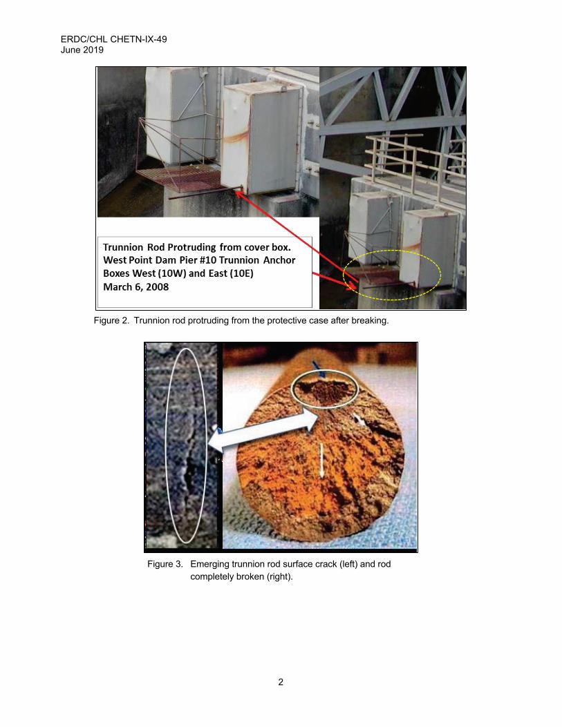
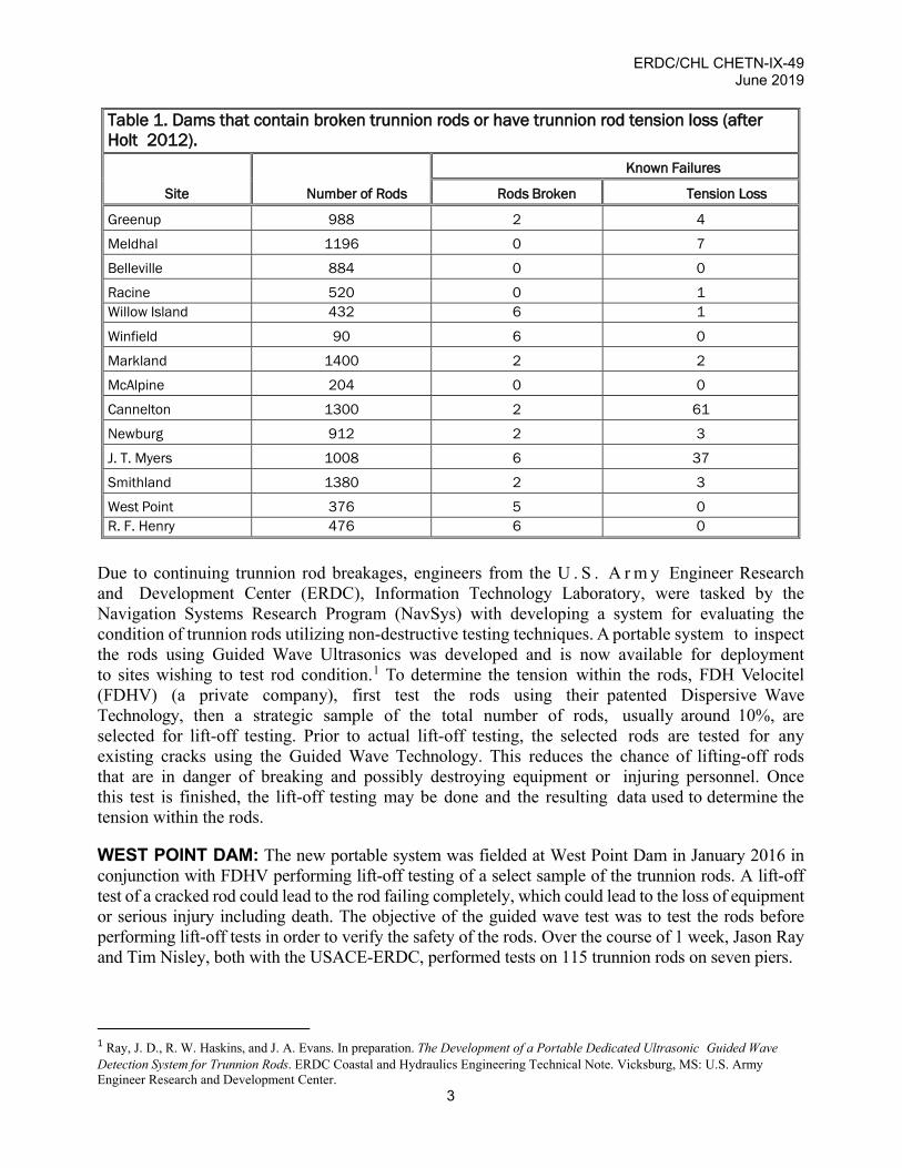
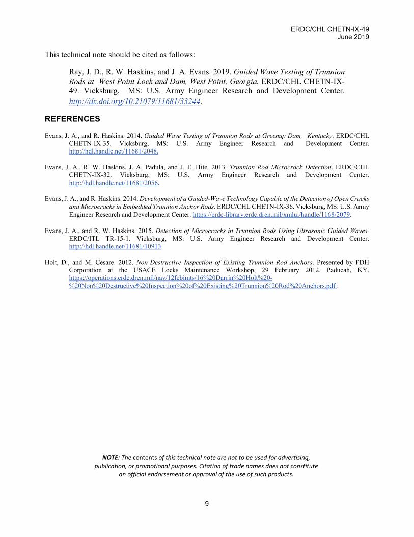
Trunnion rods are now failing at dam sites. Several of these broken rods project through the trunnion anchor cover boxes, as highlighted in Figure 2. The appearance of the cracks in the rods examined indicates that the trunnion rods had been cracked for some time prior to breaking. Stress corrosion cracking may have caused the final loss of the trunnion rod shown in Figure 3. As of 2012, 10 USACE dams contained broken trunnion rods (Table 1).
ERDC/CHL CHETN-IX-49 June 2019
2
Figure 2. Trunnion rod protruding from the protective case after breaking.
Figure 3. Emerging trunnion rod surface crack (left) and rod
completely broken (right).
ERDC/CHL CHETN-IX-49 June 2019
3
Table 1. Dams that contain broken trunnion rods or have trunnion rod tension loss (after Holt 2012).
Site Number of Rods
Known Failures
Rods Broken Tension Loss
Greenup 988 2 4
Meldhal 1196 0 7
Belleville 884 0 0
Racine 520 0 1 Willow Island 432 6 1
Winfield 90 6 0
Markland 1400 2 2
McAlpine 204 0 0
Cannelton 1300 2 61
Newburg 912 2 3
J. T. Myers 1008 6 37
Smithland 1380 2 3
West Point 376 5 0 R. F. Henry 476 6 0
Due to continuing trunnion rod breakages, engineers from the U . S . A r m y Engineer Research and Development Center (ERDC), Information Technology Laboratory, were tasked by the Navigation Systems Research Program (NavSys) with developing a system for evaluating the condition of trunnion rods utilizing non-destructive testing techniques. A portable system to inspect the rods using Guided Wave Ultrasonics was developed and is now available for deployment to sites wishing to test rod condition.1 To determine the tension within the rods, FDH Velocitel (FDHV) (a private company), first test the rods using their patented Dispersive Wave Technology, then a strategic sample of the total number of rods, usually around 10%, are selected for lift-off testing. Prior to actual lift-off testing, the selected rods are tested for any existing cracks using the Guided Wave Technology. This reduces the chance of lifting-off rods that are in danger of breaking and possibly destroying equipment or injuring personnel. Once this test is finished, the lift-off testing may be done and the resulting data used to determine the tension within the rods.
WEST POINT DAM: The new portable system was fielded at West Point Dam in January 2016 in conjunction with FDHV performing lift-off testing of a select sample of the trunnion rods. A lift-off test of a cracked rod could lead to the rod failing completely, which could lead to the loss of equipment or serious injury including death. The objective of the guided wave test was to test the rods before performing lift-off tests in order to verify the safety of the rods. Over the course of 1 week, Jason Ray and Tim Nisley, both with the USACE-ERDC, performed tests on 115 trunnion rods on seven piers.
1 Ray, J. D., R. W. Haskins, and J. A. Evans. In preparation. The Development of a Portable Dedicated Ultrasonic Guided Wave Detection System for Trunnion Rods. ERDC Coastal and Hydraulics Engineering Technical Note. Vicksburg, MS: U.S. Army Engineer Research and Development Center.

ERDC/CHL CHETN-IX-49 June 2019
4
TEST OVERVIEW: The FDHV company has been working on a system to allow determination of tension on embedded trunnion rods using dispersive wave technology. By measuring the load and rod displacement during lift-off testing, data can be fed into a model to estimate the tension of the rods by using dispersive wave testing.
To maximize personnel safety during the lift-off testing, ERDC deployed the Portable Guide Wave Ultrasonic system to check for microcracks within the rods before FDHV performed the lift-off tests. The ERDC team worked at least one pier ahead of FDHV, allowing the teams to work without being in each other’s way.
The FDHV selected 60 rods between Block 5, Pier 6, Pier 7, Pier 8, Pier 9, and Block E for testing. All rods are between 40 and 50 feet (ft) long and are 1.25 inches in diameter. Since Pier 10 had previously experienced several rod failures, FDHV would not perform lift-offs on Pier 10. However, toward the end of the work, Mobile District requested ERDC test every rod on Pier 10 with the portable system to see if there were any apparent flaws.
TEST PLAN: Safety concerns at this dam dictated that no grinding or unnecessary contact with the rods would be allowed. It was known before testing that the rod ends were, for the most part, in good shape and would not require any work to prepare the surfaces. A few rods exhibited surface anomalies (Figure 4). Other rods were very flat and were quite responsive to the test (Figure 5).
Figure 4. Pitted rod and surface corrosion on rod.

ERDC/CHL CHETN-IX-49 June 2019
5
Figure 5. Typical rod without
corrosion.
The FDHV test plan defined the testing order of the piers: Pier 8; Pier 9; Pier 7; Pier 6; Block 5; Block E; and Pier 10. Only a select number of rods were tested on these piers. Figure 6 shows the orientation of piers and trunnion rods, from a downstream perspective.
Figure 6. Pier layout, West Point Dam.
The cantilever length and the encased length were known prior to testing for all rods at West Point Dam. Knowing these parameters before testing is advantageous to both data accuracy and data collection speed because it allows the ERDC system operator to set an appropriate system capture time.
TEST METHOD: All rods for each pier were tested before moving to the next pier. First, each rod was visually inspected for proper placement of the transducer on the rod end (Figure 7). At West Point Dam, preparation for proper transducer placement involved cleaning the rod ends of caked-on grease using a putty knife. Safety procedures were observed, being careful to stay out of harm’s way by standing clear of any possible projection of the rod.

ERDC/CHL CHETN-IX-49 June 2019
6
Figure 7. Panametrics transducer (left) and transducer clamped on rod (right).
If cases where the rod ends are too rough to make adequate contact with the transducer, a Fields metal casting may be made of the rod end to interface to the transducer (Figure 8). This procedure will eliminate the need for grinding or cutting off the rod ends. This will decrease the risk of having a rod break and project out of the tube.
Figure 8. Trunnion rod end casting assembly and sample casting.
The portable guided wave test system is shown in Figure 9. It consists of three parts: a portable case containing the hardware, a laptop computer for running the embedded software and storing the data, and a transducer (Figure 7) which couples to the rod. A 25 ft RG–58 solid-core coaxial cable is used to connect the transducer to the test system.

ERDC/CHL CHETN-IX-49 June 2019
7
Figure 9. The test system and control laptop.
Testing each pier started with scanning the first rod on a range of modes to determine the optimum test frequency based on energy transfer. This frequency served as a basis for testing all other rods on that pier.
TEST RESULTS: A typical rod’s acoustical response is shown in Figure 10.
Figure 10. Typical acoustical guided waves response from rods.
A non-typical response from a rod is shown in Figure 11. Note the return midway between the exciting pulse and the end of rod reflection.

ERDC/CHL CHETN-IX-49 June 2019
8
Figure 11. Pier 10, west bundle, column 3, row 6 display, showing areas for concern.
Though the rods were of similar length, diameter, and visible condition, the level of the output varied from rod to rod. These results can be contributed to several factors, including the angle and the condition of the fixed end of the trunnion. All of the rods tested, with the exception of one (Figure 11), displayed a variation of the typical response shown in Figure 10.
Figure 11 is an annotated display of the data set from a trunnion rod on Pier 10 that displays a possible crack. Although several things could cause the unusual return in these data, the history of this particular pier makes it reasonable to suspect a crack in the rod. Additional analysis of the data set is being conducted to increase the assurance that a defect is present.
CONCLUSION: The purpose of this CHETN is twofold: ( 1 ) to describe the testing done at West Point Lock and Dam and (2) to provide an overview of the procedure used to test rods at any dam site. Of the rods that were tested at the West Point dam, one displayed a probable defect. This defect is believed to be a crack in the rod.
SUPPORT: Appreciation is extended to Technician Tim Nisley, ERDC, for his assistance on this project; George V. Poiroux, SAM; and Ron Stuckey, the Power Project Manager, whose crew provided excellent support all SAM). Additionally, appreciation is extended to all of the FDHV personnel who provided assistance on this project.
ADDITIONAL INFORMATION: This CHETN is a product of the Navigation Systems Research (NavSys) Program being conducted at the U.S. Army Engineer Research and Development Center (ERDC). Questions about this technical note may be addressed to Jason Ray; email [email protected]. Questions about the NavSys Program may be addressed to Charles E. Wiggins: [email protected].
ERDC/CHL CHETN-IX-49 June 2019
9
This technical note should be cited as follows:
Ray, J. D., R. W. Haskins, and J. A. Evans. 2019. Guided Wave Testing of Trunnion Rods at West Point Lock and Dam, West Point, Georgia. ERDC/CHL CHETN-IX-49. Vicksburg, MS: U.S. Army Engineer Research and Development Center. http://dx.doi.org/10.21079/11681/33244.
REFERENCES
Evans, J. A., and R. Haskins. 2014. Guided Wave Testing of Trunnion Rods at Greenup Dam, Kentucky. ERDC/CHL CHETN-IX-35. Vicksburg, MS: U.S. Army Engineer Research and Development Center. http://hdl.handle.net/11681/2048.
Evans, J. A., R. W. Haskins, J. A. Padula, and J. E. Hite. 2013. Trunnion Rod Microcrack Detection. ERDC/CHL CHETN-IX-32. Vicksburg, MS: U.S. Army Engineer Research and Development Center. http://hdl.handle.net/11681/2056.
Evans, J. A., and R. Haskins. 2014. Development of a Guided-Wave Technology Capable of the Detection of Open Cracks and Microcracks in Embedded Trunnion Anchor Rods. ERDC/CHL CHETN-IX-36. Vicksburg, MS: U.S. Army Engineer Research and Development Center. https://erdc-library.erdc.dren.mil/xmlui/handle/1168/2079.
Evans, J. A., and R. W. Haskins. 2015. Detection of Microcracks in Trunnion Rods Using Ultrasonic Guided Waves. ERDC/ITL TR-15-1. Vicksburg, MS: U.S. Army Engineer Research and Development Center. http://hdl.handle.net/11681/10913.
Holt, D., and M. Cesare. 2012. Non-Destructive Inspection of Existing Trunnion Rod Anchors. Presented by FDH Corporation at the USACE Locks Maintenance Workshop, 29 February 2012. Paducah, KY. https://operations.erdc.dren.mil/nav/12febimts/16%20Darrin%20Holt%20-%20Non%20Destructive%20Inspection%20of%20Existing%20Trunnion%20Rod%20Anchors.pdf .
NOTE: The contents of this technical note are not to be used for advertising, publication, or promotional purposes. Citation of trade names does not constitute
an official endorsement or approval of the use of such products.