erb-24 - bmed.mcgill.ca · v preface this manual describes how to cable, wire, program, and use...
TRANSCRIPT
ERB-24
U S E R ’ S G U I D E

ERB-24 User’s Guide
Revision B - July 1994Part Number: 63930

New Contact Information
Keithley Instruments, Inc.28775 Aurora Road
Cleveland, OH 44139
Technical Support: 1-888-KEITHLEYMonday – Friday 8:00 a.m. to 5:00 p.m (EST)
Fax: (440) 248-6168
Visit our website at http://www.keithley.com

Keithley MetraByte Division
Keithley Instruments, Inc.
440 Myles Standish Blvd. Taunton, MA 02780
Telephone: (508) 880-3000 ● FAX: (508) 880-0179
The information contained in this manual is believed to be accurate and reliable. However, Keithley Instruments, Inc., assumes no responsibility for its use or for any infringements of patents or other rights of third parties that may result from its use. No license is granted by implication or otherwise under any patent rights of Keithley Instruments, Inc.
KEITHLEY INSTRUMENTS, INC., SHALL NOT BE LIABLE FOR ANY SPECIAL, INCIDENTAL, OR CONSEQUENTIAL DAMAGES RELATED TO THE USE OF THIS PRODUCT. THIS PRODUCT IS NOT DESIGNED WITH COMPONENTS OF A LEVEL OF RELIABILITY SUITABLE FOR USE IN LIFE SUPPORT OR CRITICAL APPLICATIONS.
Refer to your Keithley Instruments license agreement and Conditions of Sale document for specific warranty and liability information.
All brand and product names are trademarks or registered trademarks of their respective companies.
© Copyright Keithley Instruments, Inc., 1992, 1994.
All rights reserved. Reproduction or adaptation of any part of this documentation beyond that permitted by Section 117 of the 1976 United States Copyright Act without permission of the Copyright owner is unlawful.

v
Preface
This manual describes how to cable, wire, program, and use ERB-24 relay output boards with digital I/O boards, such as the PIO-12.
This guide serves data acquisition system designers, engineers, technicians, programmers, scientists, and other users responsible for setting up, cabling, wiring, and writing programs that access the functionality of the ERB-24 board. This guide assumes that you are familiar with data acquisition and programming principles and with your particular application.
The ERB-24 User’s Guide is organized as follows:
● Chapter 1 briefly describes the features, applications, and accessories supported by the ERB-24.
● Chapter 2 describes the features of the ERB-24 in more detail and provides a block diagram of the board.
● Chapter 3 describes how to unpack and set up the ERB-24 board.
● Chapter 4 describes how to attach the ERB-24 to digital I/O boards.
● Chapter 5 provides an example of accessing the functionality of an ERB-24 board using a PIO-12 board and the BASIC programming language.
● Chapter 6 provides troubleshooting information and information on how to obtain technical support and repairs for the ERB-24.
● Appendix A lists the specifications for the ERB-24.
● Appendix B lists the connector pin assignments for the ERB-24.
An index completes this guide.

Table of Contents
iii
Preface
1 OverviewFeatures . . . . . . . . . . . . . . . . . . . . . . . . . . . . . . . . . . . . . . . . . . . .1-1Applications . . . . . . . . . . . . . . . . . . . . . . . . . . . . . . . . . . . . . . . . .1-2Accessories. . . . . . . . . . . . . . . . . . . . . . . . . . . . . . . . . . . . . . . . . .1-2
2 Functional Description
3 SetupUnpacking the Board . . . . . . . . . . . . . . . . . . . . . . . . . . . . . . . . . .3-1Setting the AC Line Voltage . . . . . . . . . . . . . . . . . . . . . . . . . . . . .3-2
4 Cabling and WiringConnector Pin Assignments . . . . . . . . . . . . . . . . . . . . . . . . . . . . .4-1Attaching to a PIO-12, PIO-24, µCPIO-12, or µCPIO-24 . . . . . .4-4Attaching to the DAS-1600 or DAS-1200 Series . . . . . . . . . . . .4-5Attaching to a PIO-96 . . . . . . . . . . . . . . . . . . . . . . . . . . . . . . . . .4-6
5 ProgrammingPIO-12 Relay Signal Names . . . . . . . . . . . . . . . . . . . . . . . . . . . .5-1BASIC Example. . . . . . . . . . . . . . . . . . . . . . . . . . . . . . . . . . . . . .5-2
6 TroubleshootingProblem Isolation . . . . . . . . . . . . . . . . . . . . . . . . . . . . . . . . . . . . .6-1Technical Support. . . . . . . . . . . . . . . . . . . . . . . . . . . . . . . . . . . . .6-2
A Specifications
B Connector Pin Assignments37-Pin Connector . . . . . . . . . . . . . . . . . . . . . . . . . . . . . . . . . . . . B-150-Pin Connector . . . . . . . . . . . . . . . . . . . . . . . . . . . . . . . . . . . . B-2

iv
Index
List of FiguresFigure 2-1. ERB-24 Block Diagram. . . . . . . . . . . . . . . . . . . . .2-2Figure 2-2. Typical Relay Channel. . . . . . . . . . . . . . . . . . . . . .2-2Figure 3-1. ERB-24 Board Layout . . . . . . . . . . . . . . . . . . . . . .3-2Figure 4-1. Pin Assignments of the 37-Pin Connector (J14) . .4-2Figure 4-2. Pin Assignments of the 50-Pin Connector (J15) . .4-3Figure 4-3. Attaching to a PIO-12, PIO-24, µCPIO-12, or
µCPIO-24 Board . . . . . . . . . . . . . . . . . . . . . . . . . .4-4Figure 4-4. Attaching to a DAS-1600 or DAS-1200 Series
Board . . . . . . . . . . . . . . . . . . . . . . . . . . . . . . . . . . .4-5Figure 4-5. Attaching to a PIO-96 Board . . . . . . . . . . . . . . . . .4-6Figure B-1. Pin Assignments for the 37-Pin Connector (J14) B-1Figure B-2. Pin Assignments for the 50-Pin Connector (J15) B-2
List of TablesTable 5-1. PIO-12 Relay Signals. . . . . . . . . . . . . . . . . . . . . . .5-1Table 6-1. Troubleshooting Information . . . . . . . . . . . . . . . . .6-2Table A-1. ERB-24 Specifications. . . . . . . . . . . . . . . . . . . . . A-1
1-1
1Overview
The ERB-24 is a 24-channel relay output board. This chapter describes the features and typical applications of the ERB-24 and the accessories provided for the board.
Features
The ERB-24 is compatible with the PIO-12, PIO-24, PIO-96, µCPIO-12, and µCPIO-24 digital I/O boards. The ERB-24 is also compatible with the digital I/O section of the DAS-1600 Series and DAS-1200 Series boards.
The ERB-24 provides the following features:
● 24 double-pole, double-throw relays (dual form C)
● 3 A contact rating (120 Vrms)
● Built-in power supply
● Screw terminals that accept 12-22 AWG wire
● LEDs that indicate activated relays
● 37-pin connector
● 50-pin connector
1-2 Overview
Applications
The following are typical applications for the ERB-24:
● Energy management
● Laboratory automation
● Product testing
● Process control
● Alarm activation
● Annunciator lighting
Accessories
The optional accessories for the ERB-24 board include the following:
● C-1800 - Cable for connecting an ERB-24 to a PIO-12, PIO-24, µCPIO-12, µCPIO-24, DAS-1600 Series, or DAS-1200 Series board. The standard cable is 1.5 feet long. The C-1800 cable is available in different lengths, if required. Refer to the Keithley MetraByte catalog for more information on ordering the C-1800 in different lengths.
● CACC-2000 - Cable for connecting an ERB-24 to a PIO-96 digital I/O board.
● RMT-02 - Rack-mountable enclosure. The RMT-02 installs into any standard 19-inch rack, such as a Keithley MetraByte RMF-06 or RTT-02.
● SFC-37 - 37-pin mating connector for making custom digital inputs.

2-1
2Functional Description
Each of the 24 relays on the ERB-24 board is supported by its own control line. The relay is an electromechanical, dual form C (double-pole, double-throw) module capable of switching loads under program control. The electromechanical relays offer zero-leakage output currents.
Each relay contains two normally open contacts and two normally closed contacts. Each contact can switch up to 3 A (resistive) at 120 Vrms.
The ERB-24 provides both a 37-pin and a 50-pin connector. The 37-pin connector is provided for connecting to a PIO-12, PIO-24, µCPIO-12, or µCPIO-24 digital I/O board or to the 37-pin auxiliary connector on a DAS-1600 Series or DAS-1200 Series board. The 50-pin connector is provided for connecting to a PIO-96 digital I/O board.
A 5 V signal applied to the corresponding relay control pin on the connector energizes the relay. Onboard transistor drivers allow control of the ERB-24 by any LSTTL- or NMOS/ CMOS-compatible digital output board.
The ERB-24 contains an annunciator LED for each relay for purposes of monitoring and troubleshooting. Each annunciator LED lights when its associated relay is energized.
The board also contains its own power supply. The power supply operates on 115/230 VAC and accepts 15% voltage fluctuations. Operating temperatures range from 0° to 60°C.
A block diagram of the ERB-24 board is shown in Figure 2-1. Figure 2-2 shows the circuitry for a single relay channel.

2-2 Functional Description
Figure 2-1. ERB-24 Block Diagram
Figure 2-2. Typical Relay Channel
24 DarlingtonTransistor Drivers
Relay 0
Relay 23
Relays0 to 23
.
.
.
.
.
.
For Relays0 to 23
.
.
PowerSupply
TTLSignals
FromDigitalI/OBoard
115/230 Vat 50/60 Hz Notes: NC = Normally Closed
NO = Normally Open C = Common
.
.
.
NC ANO AC ANC BNO BC B
NC ANO AC ANC BNO BC B
3-1
3Setup
This chapter describes how to set up your ERB-24 board. If you encounter any problems with the board after setting it up, refer to Chapter 6 for troubleshooting information.
Unpacking the Board
Caution: A discharge of static electricity from your hands can seriously damage certain electrical components on any circuit board. It is recommended that you use wrist strap grounds when handling a board. If a wrist strap ground is not available, make sure that you discharge static electricity from yourself by touching a grounded conductor such as your computer chassis (your computer must be turned off).
Whenever you handle a board, hold it by the edges and avoid touching any board components.
Use the following procedure to unpack an ERB-24 board:
1. Remove the board from its anti-static wrapping material. You may wish to store the wrapping material for possible future use.
2. Inspect the board for signs of damage. If damage is apparent, arrange to return the board (see page 6-2).
3. Check the remaining contents of your package against the packing list to be sure your order is complete. Report any missing items, immediately.

3-2 Setup
4. Once you have determined that the board is acceptable, select the appropriate AC line voltage, as described in the next section.
Setting the AC Line Voltage
Caution: Be sure to set the AC line voltage for the voltage you are using before connecting the ERB-24 to line power. The default setting is 115 V.
The 115/230 AC Line Voltage Selector is a 2-position slide switch located as shown in Figure 3-1. To change the line voltage setting, slide the switch to the appropriate setting (115 V or 230 V) marked on the switch.
Figure 3-1. ERB-24 Board Layout
Once you have set the AC line voltage, you can attach accessories and wire applications to the ERB-24 board, as discussed in Chapter 4.
AC Line Voltage Selector
Fuse
232221201918171615141312
11109876543210
Screw Terminals
Screw Terminals
37-Pin Connector
Transformer
ACPower Input
J15, 50-Pin ConnectorJ14LEDs
J13
4-1
4Cabling and Wiring
Once you have set up the ERB-24, you can attach accessories and wire applications to the board. This chapter describes the pin assignments of the connectors on the ERB-24 and how to attach the ERB-24 to digital I/O boards.
Connector Pin Assignments
The ERB-24 board contains two connectors: a 37-pin, D-type, male connector (J14) and a 50-pin connector (J15), shown in Figure 3-1. The pin assignments of the 37-pin connector are shown in Figure 4-1; the pin assignments of the 50-pin connector are shown in Figure 4-2.

4-2 Cabling and Wiring
Figure 4-1. Pin Assignments of the 37-Pin Connector (J14)
N/C Pin 19N/C Pin 18N/C Pin 17N/C Pin 16N/C Pin 15N/C Pin 14N/C Pin 13N/C Pin 12DIG COM Pin 11Relay 16 Pin 10Relay 17 Pin 9Relay 18 Pin 8Relay 19 Pin 7Relay 20 Pin 6Relay 21 Pin 5Relay 22 Pin 4Relay 23 Pin 3N/C Pin 2N/C Pin 1
Pin 37 Relay 0Pin 36 Relay 1Pin 35 Relay 2Pin 34 Relay 3Pin 33 Relay 4Pin 32 Relay 5Pin 31 Relay 6Pin 30 Relay 7Pin 29 Relay 8Pin 28 Relay 9Pin 27 Relay 10 Pin 26 Relay 11 Pin 25 Relay 12 Pin 24 Relay 13 Pin 23 Relay 14 Pin 22 Relay 15 Pin 21 DIG COMPin 20 N/C

4-3
Figure 4-2. Pin Assignments of the 50-Pin Connector (J15)
Relay 7 Pin 1Relay 6 Pin 3Relay 5 Pin 5Relay 4 Pin 7Relay 3 Pin 9Relay 2 Pin 11Relay 1 Pin 13Relay 0 Pin 15Relay 15 Pin 17Relay 14 Pin 19Relay 13 Pin 21Relay 12 Pin 23Relay 11 Pin 25Relay 10 Pin 27Relay 9 Pin 29Relay 8 Pin 31Relay 23 Pin 33Relay 22 Pin 35Relay 21 Pin 37Relay 20 Pin 39Relay 19 Pin 41Relay 18 Pin 43Relay 17 Pin 45Relay 16 Pin 47N/C Pin 49
Pin 2 GndPin 4 GndPin 6 GndPin 8 GndPin 10 GndPin 12 GndPin 14 GndPin 16 GndPin 18 GndPin 20 GndPin 22 GndPin 24 GndPin 26 GndPin 28 GndPin 30 GndPin 32 GndPin 34 GndPin 36 GndPin 38 GndPin 40 GndPin 42 GndPin 44 GndPin 46 GndPin 48 GndPin 50 Gnd

4-4 Cabling and Wiring
Attaching to a PIO-12, PIO-24, µCPIO-12, or µCPIO-24
To attach the ERB-24 to a PIO-12, PIO-24, µCPIO-12, or µCPIO-24 digital I/O board, connect a C-1800 cable to the 37-pin connector on the ERB-24 (J14), as shown in Figure 4-3.
Figure 4-3. Attaching to a PIO-12, PIO-24, µCPIO-12, or µCPIO-24 Board
ERB-24
PIO-12, PIO-24, µCPIO-12, or µCPIO-24 board
C-1800
J14

4-5
Attaching to the DAS-1600 or DAS-1200 Series
To attach the ERB-24 to a DAS-1600 or DAS-1200 Series board, first attach the DAS board end of the PIO cable that comes with the DAS-1600 and DAS-1200 Series boards to the PIO cable connector (J2) on the DAS board. Next, install the 37-pin D-type connector of the PIO cable in the connector panel next to the main I/O connector (J1) of the DAS-1600 or DAS-1200 Series board. Finally, attach connector J14 on the ERB-24 to the 37-pin D-type connector of the PIO cable with the C-1800 cable. Figure 4-4 illustrates these connections.
Figure 4-4. Attaching to a DAS-1600 or DAS-1200 Series Board
DAS-1600 or DAS-1200 Series board
C-1800 cable
J2
PIO cable ERB-24
J14

4-6 Cabling and Wiring
Attaching to a PIO-96
You can attach up to four ERB-24 boards to a PIO-96 digital I/O board. To attach an ERB-24 to a PIO-96, connect the CACC-2000 cable to the 50-pin connector (J15) on the ERB-24 board and to the 50-pin connector on the PIO-96, as shown in Figure 4-5.
Figure 4-5. Attaching to a PIO-96 Board
PIO-96 board
ERB-24ERB-24ERB-24
J1J2J3J4
ERB-24
CACC-2000Cable
J15J15
CACC-2000CableCACC-2000
CableCACC-2000Cable
J15J15
5-1
5Programming
This chapter provides an example of how to activate relays on the ERB-24 using a PIO-12 digital I/O board and BASIC as the programming language.
PIO-12 Relay Signal Names
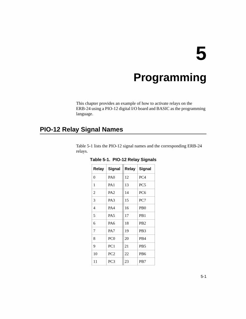
Table 5-1 lists the PIO-12 signal names and the corresponding ERB-24 relays.
Table 5-1. PIO-12 Relay Signals
Relay Signal Relay Signal
0 PA0 12 PC4
1 PA1 13 PC5
2 PA2 14 PC6
3 PA3 15 PC7
4 PA4 16 PB0
5 PA5 17 PB1
6 PA6 18 PB2
7 PA7 19 PB3
8 PC0 20 PB4
9 PC1 21 PB5
10 PC2 22 PB6
11 PC3 23 PB7

5-2 Programming
BASIC Example
The following simple BASIC program activates relays on the ERB-24 used with a PIO-12 board:
10 OUT &H313, &H80 ’Sets all PIO-12 ports to outputs20 OUT &H310, 1 ’Activates relay 0 (Port A, Bit 0)30 OUT &H311, 16 ’Activates relay 20 (Port B, Bit 4)40 OUT &H312, 3 ’Activates relays 8 and 9 ’(Port C, Bits 0 and 1)

6-1
6Troubleshooting
If your ERB-24 board is not operating properly, use the information in this chapter to help you isolate the problem. If the problem appears serious enough to require technical support, refer to page 6-2 for information on how to contact an applications engineer.
Problem Isolation
If you encounter a problem with an ERB-24 board, use the troubleshooting information in Table 6-1 to try to isolate the problem. Table 6-1 lists general symptoms and possible solutions for problems with ERB-24 boards.

6-2 Troubleshooting
If your board is not operating properly after using the information in Table 6-1, refer to the next section for information on how to contact an applications engineer.
Technical Support
Before returning any equipment for repair, call the Keithley MetraByte Hardware Applications Engineering Department at:
(508) 880-3000
Monday - Friday, 8:00 A.M. - 6:00 P.M., Eastern Time
Table 6-1. Troubleshooting Information
Symptom Possible Cause Possible Solution
Board does not respond
The board is damaged. Contact the Keithley Applications Engineering Department; see page 6-2.
Bad cable or cable not connected. Check cable connections. Replace cable if defective.
No A/C or power cord not plugged in.
Check power connections to board.
Intermittent operation
Vibrations or loose connections exist.
Cushion source of vibration and tighten connections. Check cable.
The board is overheating. Check environmental and ambient temperature. See the documentation for your computer for specifications.
Electrical noise exists. Provide better shielding or reroute wiring.
Data appears to be invalid
An open connection exists. Check wiring to screw terminal.
Outputs not indicating proper level.
Check that the circuit is complete (are both relay connections used?).
You may need to apply pull-up resistors for the external source.

6-3
An applications engineer will help you diagnose and resolve your problem over the telephone. Please make sure that you have the following information available before you call:
ERB-24 Serial # _____________________Board Revision code _____________________
VAC line voltage _____________________
Digital I/O Board Type _____________________Serial # _____________________Base address _____________________Interrupt selection _____________________
Computer Manufacturer _____________________CPU type 8088, 286, 386, 486,
Pentium, ____________Clock speed (MHz) 8 12 20 25 33 ____Math coprocessor Yes NoAmount of RAM _____________________Video system CGA Hercules EGA VGABIOS type _____________________
Operating system DOS version _____________________Windows version 3.0 3.1 _____________Windows mode Standard Enhanced
Software package Name _____________________(if applicable) Version _____________________
Invoice/order # _____________________
Compiler Language _____________________(if applicable) Manufacturer _____________________
Version _____________________

6-4 Troubleshooting
If a telephone resolution is not possible, the applications engineer will issue you a Return Material Authorization (RMA) number and ask you to return the equipment. Include the RMA number with any documentation regarding the equipment.
When returning equipment for repair, include the following information:
● Your name, address, and telephone number.
● The invoice or order number and date of equipment purchase.
● A description of the problem or its symptoms.
● The RMA number on the outside of the package.
Repackage the equipment, using the original anti-static wrapping, if possible, and handling it with ground protection. Ship the equipment to:
ATTN: RMA #_______Repair DepartmentKeithley MetraByte
440 Myles Standish BoulevardTaunton, Massachusetts 02780
Telephone (508) 880-3000Telex 503989
FAX 508/880-0179
Notes: If you are submitting your equipment for repair under warranty, you must include the invoice number and date of purchase.
To enable Keithley Metrabyte to respond as quickly as possible, you must include the RMA number on the outside of the package.

A-1
ASpecifications
Table A-1 lists the specifications for the ERB-24.
Table A-1. ERB-24 Specifications
Feature Attribute Specification
Relays Quantity and type 24 DPDT, dual form C
Contact material Gold overlay silver
Contact rating 3 A at 28 VDC, resistive3 A at 120 VAC, resistive1.6 A at 220 VAC
Operate time 20 ms maximum at rated voltage
Release time 10 ms maximum
Life expectancy Mechanical Electrical
107 operations/minute
105 operations/minute at rated load
Environmental Operating temperature rangeStorage temperature rangeHumidity
0° to 60°C−40° to +100°C0 to 90% noncondensing
Power Consumption
Input power 115 VAC ±15% (2 A fuse)230 VAC ±15% (1 A fuse)50/60 Hz, 14.5 VA maximum
A-2 Specifications
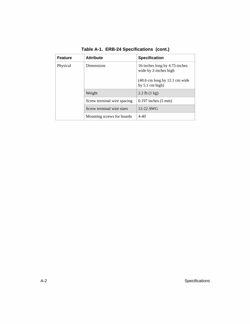
Physical Dimensions 16-inches long by 4.75-inches wide by 2-inches high
(40.6 cm long by 12.1 cm wide by 5.1 cm high)
Weight 2.2 lb (1 kg)
Screw terminal wire spacing 0.197 inches (5 mm)
Screw terminal wire sizes 12-22 AWG
Mounting screws for boards 4-40
Table A-1. ERB-24 Specifications (cont.)
Feature Attribute Specification

B-1
BConnector Pin Assignments
This appendix contains the pin assignments for the ERB-24 board connectors.
37-Pin Connector
Pin assignments for the 37-pin connector, J14, on the ERB-24 are shown in Figure B-1.
Figure B-1. Pin Assignments for the 37-Pin Connector (J14)
N/C Pin 19N/C Pin 18N/C Pin 17N/C Pin 16N/C Pin 15N/C Pin 14N/C Pin 13N/C Pin 12DIG COM Pin 11Relay 16 Pin 10Relay 17 Pin 9Relay 18 Pin 8Relay 19 Pin 7Relay 20 Pin 6Relay 21 Pin 5Relay 22 Pin 4Relay 23 Pin 3N/C Pin 2N/C Pin 1
Pin 37 Relay 0Pin 36 Relay 1Pin 35 Relay 2Pin 34 Relay 3Pin 33 Relay 4Pin 32 Relay 5Pin 31 Relay 6Pin 30 Relay 7Pin 29 Relay 8Pin 28 Relay 9Pin 27 Relay 10 Pin 26 Relay 11 Pin 25 Relay 12 Pin 24 Relay 13 Pin 23 Relay 14 Pin 22 Relay 15 Pin 21 DIG COMPin 20 N/C
B-2 Connector Pin Assignments
50-Pin Connector
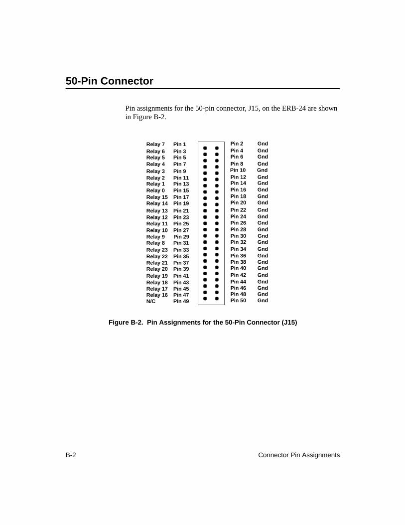
Pin assignments for the 50-pin connector, J15, on the ERB-24 are shown in Figure B-2.
Figure B-2. Pin Assignments for the 50-Pin Connector (J15)
Pin 2 GndPin 4 GndPin 6 GndPin 8 GndPin 10 GndPin 12 GndPin 14 GndPin 16 GndPin 18 GndPin 20 GndPin 22 GndPin 24 GndPin 26 GndPin 28 GndPin 30 GndPin 32 GndPin 34 GndPin 36 GndPin 38 GndPin 40 GndPin 42 GndPin 44 GndPin 46 GndPin 48 GndPin 50 Gnd
Relay 7 Pin 1Relay 6 Pin 3Relay 5 Pin 5Relay 4 Pin 7Relay 3 Pin 9Relay 2 Pin 11Relay 1 Pin 13Relay 0 Pin 15Relay 15 Pin 17Relay 14 Pin 19Relay 13 Pin 21Relay 12 Pin 23Relay 11 Pin 25Relay 10 Pin 27Relay 9 Pin 29Relay 8 Pin 31Relay 23 Pin 33Relay 22 Pin 35Relay 21 Pin 37Relay 20 Pin 39Relay 19 Pin 41Relay 18 Pin 43Relay 17 Pin 45Relay 16 Pin 47N/C Pin 49

X-1
Index
Numerics37-pin connector 2-1
pin assignments 4-2, B-150-pin connector 2-1
pin assignments 4-3, B-2
AAC line voltage 3-2accessories 1-2
C-1800 1-2CACC-2000 1-2RMT-02 1-2SFC-37 1-2
applications 1-2Applications Engineering Department 6-2attaching
DAS-1200 Series 4-5DAS-1600 Series 4-5µCPIO-12 4-4µCPIO-24 4-4PIO-12 4-4PIO-24 4-4PIO-96 4-6
BBASIC example 5-2block diagram 2-2board layout 3-2
CC-1800 1-2, 4-4, 4-5cabling 4-1CACC-2000 1-2, 4-6connector pin assignments 4-1connectors 2-1contacts 1-1, 2-1
DDAS-1200 Series 1-1
attaching 4-5DAS-1600 Series 1-1
attaching 4-5
Eenergizing a relay 2-1example 5-2
Ffeatures 1-1functional description 2-1
Ggetting help 6-2
Iisolating problems 6-1

X-2 Index
JJ14 4-2J15 4-3
Llayout 3-2LED 1-1, 2-1line voltage 3-2
MµCPIO-12 1-1
attaching 4-4µCPIO-24 1-1
attaching 4-4
Ppin assignments 4-1
37-pin connector 4-2, B-150-pin connector 4-3, B-2
PIO cable 4-5PIO-12 1-1
attaching 4-4relay signal names 5-1
PIO-24 1-1attaching 4-4
PIO-96 1-1attaching 4-6
power supply 1-1, 2-1problem isolation 6-1programming 5-1
Rrelay channel 2-2relays 1-1returning equipment 6-4RMA number 6-4RMT-02 1-2
Sscrew terminals 1-1setting the AC line voltage 3-2setting up the ERB-24 3-1SFC-37 1-2specifications A-1
Ttechnical support 6-2transistor drivers 2-1troubleshooting 6-1
Uunpacking the board 3-1
Wwarranty repairs 6-4