equilibrium phase relationships in the cao-mgo-sio -cr o3 slags502581/fulltext01.pdf ·...
TRANSCRIPT

Equilibrium phase relationships in the
CaO-MgO-SiO2-Cr2O3 slags
Yang Yang
Master Thesis
Division of Materials Process Science
Department of Materials Science and Engineering
Royal Institute of Technology
SE-100 44 Stockholm
Sweden

ABSTRACT
In pyrometallurgical processes, slags are used to prevent oxidation
of the metal through contact with air, to limit heat losses through
radiation and to remove impurities from the molten metal. The
thermodynamics of compositions in molten slags is an important area in
the field of process metallurgy. In order to optimize the metallurgical
process, it’s necessary to investigate the properties of industrial slag
systems.
Chromium is the metal in slag that is given the most attention when
it comes to leaching. Several types of slag contain a significant fraction of
oxidized chromium. This is especially the case for ferrochromium and
stainless steel slags. Knowledge of the thermodynamic properties of
chromium oxides-containing slags is very important to chromium
retention in stainless steel production, due to the chromium impacts on
economic costs and environmental protection.
In the present study, phase equilibrium of
CaO-MgO-SiO2-Cr2O3-Al2O3 synthetic slag system was investigated.
Chromium distribution, phase composition and microstructures in the
sample were analyzed using SEM, XRD, EDS techniques.
It is shown that Al2O3 favored the formation of spinel which was in
the formula of Mg(Al,Cr)2O4. With increasing addition of Al2O3,
chromium bounded in spinel phase was replaced by aluminum. When
12wt% of Al2O3 was added to the sample with basicity 1.6,
alumina-magnesia spinel, MgAl2O4, was formed.
Key words: Phase equilibrium, spinel, basicity, Al2O3

ACKNOWLEDGEMENTS
First and foremost, I would like to express my sincere gratitude to
my supervisor, Docent Lidong Teng, for giving me the opportunity to
join in the Division of Materials Process Science. This step is the
footstone to further my knowledge and develop my research ability.
Thank you for your kind guidance and encouragement in this whole
stage.
Many thanks should also be sent to Galina, for showing me how to
prepare for experiments at the beginning.
I am grateful to Mr. Peter Kling for his technical support and good
offering of tea and nice bread during my study.
I also express my thanks to Wenting Ma, Cen Zhang, Yuze Gong,
Hansheng Wang and Nian Zhou, for their friendship and support during
my last two years in Stockholm. It’s difficult to imagine the life without
all of you.
Finally, I would like to thank my parents for their support. It’s you
that encouraged me to make the first step for this amazing experience.
Financial support for the project from Swedish Foundation for
Strategic Environmental Research (MISTRA-88035) through
Jernkontoret is gratefully acknowledged.
Yang Yang (杨阳)
January 2012, Stockholm, Sweden

1. Introduction
1.1 General Information
Slag plays an important role in pyrometallurgical process.
Chromium, niobium and vanadium are important alloying elements for
production of high alloyed steels, such as stainless steel. As these
elements normally have several valences, steel making slag often has
different oxides for same element. Chromium is an essential element for
stainless steel. During processing of these steels, chromium goes to slag
phase as oxides because it is more sensitive to oxidation than iron. In
order to avoid this lost, it is necessary to study thermodynamics of
chromium oxides in slag.
Steelmaking plant produces a large amount of by-products. Steel
slag is quite useful in construction attributing to its strength and durability.
But there are still some problems which may hinder the use of slag
products. For example, chromium normally exists as 2+ or 3+ in slags,
which can be oxidized to hexavalent state (Cr6+
) in acidic and oxygen rich
environment. Thus utilization of chromium containing slag is restricted.

1.2 Motivation
During melting of scarp in EAF, most of chromium is oxidized into
slag phase. Thus lost of chromium is a big problem in stainless steel
making process. Some of EAF slag has high potential of Cr leaching. As
a result, stabilizing of chromium into mineralogical phases becomes a
quite interesting topic. Based on this, someone suggested addition of slag
formers which can either decrease basicity or favor formation of spinel
phase. For example, Al2O3 and MgO can increase the amount of spinel
phase and efficiently decrease activity of chromium leading to
stabilization of chromium.
As shown in Fig 1.1, leaching property of EAF slag depends on the
amount of MgO, Al2O3, FeOn and Cr2O3.
Fig 1.1 Results of laboratory tests on adding MgO, Al2O3 and FeO to liquid slags on the
leaching of Cr [1]
.
Fig 1.2 shows that chromium is stabled in spinel phase which is
considered as a stable phase in slag system.
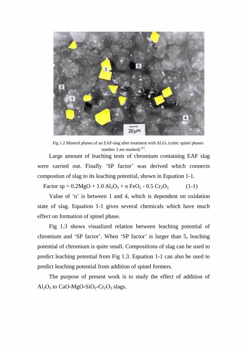
Fig 1.2 Mineral phases of an EAF-slag after treatment with Al2O3 (cubic spinel phases
number 3 are marked) [2]
.
Large amount of leaching tests of chromium containing EAF slag
were carried out. Finally ‘SP factor’ was derived which connects
compostion of slag to its leaching potential, shown in Equation 1-1.
Factor sp = 0.2MgO + 1.0 Al2O3 + n FeOx - 0.5 Cr2O3 (1-1)
Value of ‘n’ is between 1 and 4, which is dependent on oxidation
state of slag. Equation 1-1 gives several chemicals which have much
effect on formation of spinel phase.
Fig 1.3 shows visualized relation between leaching potential of
chromium and ‘SP factor’. When ‘SP factor’ is larger than 5, leaching
potential of chromium is quite small. Compositions of slag can be used to
predict leaching potential from Fig 1.3. Equation 1-1 can also be used to
predict leaching potential from addition of spinel formers.
The purpose of present work is to study the effect of addition of
Al2O3 to CaO-MgO-SiO2-Cr2O3 slags.

Fig 1-3 Chrome leaching of reduced EAF-slags from high alloy steelmaking versus “factor
sp” [2]
.
1.3 Reference
[1] Kuehn, M., Behmenburg, H., 2000. Decreasing the scorification of chrome.
Report EUR 19382. Primary Steelmaking, Luxembourg: European Commission 39;
2000.
[2] Dirk M, Kuehn M., et al., “Chrome Immobilisation in EAF-Slags from High-alloy
Steelmaking: Tests at FehS-Institute and Development of an Operational Slag
Treatment Process”, 1st International Slag Valorisation Symposium, Leuven, 2009.

2. Experimental work
2.1 Raw materials
Chemicals used in this investigation are listed in Table 2.1. CaO,
MgO and Al2O3 powders were heated at 1273K for 12 hours in a muffle
furnace to decompose any hydroxides and carbonates. SiO2 and Cr2O3
powders were dried at 383K for 10 hours to remove the moisture. The
powders of the above five oxides were carefully weighed and
homogeneously mixed in an agate mortar. Then the mixtures were
pressed into pellets with diameter of 15mm. Platinum crucibles which
were used to hold the pellets were made of Pt foil with a thickness of
0.127mm.
Table 2.1. Chemicals used in the present work
Chemicals Purity Supplier
Calcium oxide Reagent plus, 99.9% Alfa Aesar, Germany
Silicon oxide Pro analyse grade, 99.5% Alfa Aesar, Germany
Aluminium oxide 99.7% Sigma Aldrich, Germany
Magnesium oxide Pro analyse grade Sigma Aldrich, Germany
Chromium oxide 99.9% Sigma Aldrich, Germany
Platinum foil 0.127mm, 99.99% Alfa Aesar, Germany
2.2 Experimental set-up
Fig 2.1 Schematic diagram of the construction inside the horizontal furnace

Fig 2.2 Photo of the horizontal furnace
A sketch of the furnace is shown in Fig 2.1. It is controlled by a
Eurotherm PID controller equipped with a Pt-Rh30% / Pt-Rh6%
thermocouple as the sensor. This high temperature furnace is equipped
with molybdenum disilicide heating elements.
Slag samples were put in platinum crucibles and then placed in an
alumina holder. In order to prevent creeping up of the liquid slag along
the crucible walls, a platinum spiral made of a wire with 0.5mm diameter
was put inside the slag samples. The alumina holder was placed in the
even-temperature zone of the furnace. The temperature deviation at the
even temperature zone was found to be less than ±3K. The heating rate
of the apparatus is 5K/min. The gas was delivered by a narrow alumina
tube directly to the above of the sample. In literature [1, 2], 20 hours was

sufficient for slag/gas/crucible equilibrium. The isothermal time was set
for 24 hours in the present study. In order to confirm the attainment of
equilibrium under present experiments, line scan analysis of the cross
section of Pt crucible was carried out. It proved that chromium
distribution across the thickness of the Pt foil was uniform, which is
shown in Fig 2.3 ( red line for w(Pt), green line for w(Cr) ). After
equilibrating, the samples were quenched by putting them into cold water.
Fig 2.4 shows the appearance of the prepared sample.
Fig 2.3 Line scan analysis of the cross section of Pt crucible
Fig 2.4 Appearance of the prepared sample

2.3 Analysis methods
2.3.1 X-ray diffraction analysis
All samples were grinded into fine powder for XRD. A Siemens D
5000 X-ray diffractometer was used for analysis. Parameters used in
analysis are shown in Table 2.2.
Table 2.2 Parameters used in XRD analysis (using copper Kα radiation)
2-theta range 20°-70°
Scan speed 1 sec/step
Scan type locked coupled
Increment 0.02°/step
2.3.2 Scanning electron microscope investigation
The mineralogy of the slag sample was analyzed by Hitachi S3700N
SEM using backscattered electron image signal. Semi-quantitative and
qualitative elemental analyses were performed with an energy dispersive
spectroscopy (EDS). Sample fragments were collected and mounted in a
conductive epoxy resin to prepare specimens for SEM. Thereafter, the
specimens were grounded and polished. Finally, surfaces of the
specimens were sputter coated with a conductive layer of gold.

2.4 Experimental procedure
Heating cycle of the experiment is shown in Fig 2.5.
Fig 2.5 Heating cycle of the experiment
Compositions of slag sample are shown in Table 2.3.
Table 2.3 Compositions of the slags under investigation at present study
Basicity Al2O3(wt%) Weight percent of oxides in slag composition (wt%)
CaO SiO2 MgO Cr2O3
1.0 12.0 37.0 37.0 8.0 6.0
1.4 3.0 48.4 34.6 8.0 6.0
12.0 43.2 30.8 8.0 6.0
1.6
3.0 51.1 31.9 8.0 6.0
6.0 49.2 30.8 8.0 6.0
8.0 48.0 30.0 8.0 6.0
12.0 45.5 28.5 8.0 6.0
1.8 8.0 50.1 27.9 8.0 6.0
12.0 47.6 26.4 8.0 6.0
2.5 Reference
[1] E. B. Pretorius and A. Muan: J. Am. Ceram. Soc.,75 (1992), 6, 1364.
[2] L. Dong, X. D. Wang and S. Seetharaman: Steel Research Intern, 80(2009), 3,
202.
5K/min
1600℃, 24h 3K/min
1400℃, 24h
quenching
room temperature

3. Results and discussion
3.1 Microstructure and phase analysis
Fig 3.1 Scanning electron microgragh for slag sample.
Fig 3.1 shows the microstructure of sample of bisicity 1.0 with 12%
Al2O3 addition. Together with EDS analysis, the bright phase with square
shape is spinel phase of MgCr2O4 type which has some amount of
aluminum solid solution. Well developed spinel phase in blocks of square
shape precipitated homogeneously in matrix phase. At the same time, the
amount of aluminum distributes homogeneously between matrix and
spinel. From Fig 3.2, XRD pattern of slag sample shows that matrix is
mostly amorphous, but spinel phase has appeared. This is in agreement

with the SEM results.
Fig 3.2 XRD patterns for slag sample
Fig 3.3 shows the microstructure of sample of bisicity 1.4 with 3%
Al2O3 addition. Together with Table 3.1, phase at point 8 stands for spinel
of MgCr2O4 type with small amount of aluminum. Phase at point 9
represents calcium silicate (Ca2SiO4) while point 10 is Ca3Si2O7.
Fig 3.3 Scanning electron microgragh for slag sample.

Matrix phase with dark color was liquid during heat treatment.
During cooling, small particle of spinel precipitated from matrix.
Table 3.1 EDS analysis of points shown in Fig 3.3.
Ca Mg Si Cr Al O
(8) 1.18 14.76 0.18 29.84 4.81 49.23
(9) 34.37 2.62 15.09 0.69 0.39 46.83
(10) 25.26 1.87 16.93 1.54 4.34 50.06
Fig 3.4 Scanning electron microgragh for slag sample B=1.4 with 12%Al2O3.
a)
b)

As shown in Fig 3.4 a), more phases precipitated with 12% Al2O3
addition. Together with Table 3.2, point 1 and point 5 represent spinel of
Mg(Al, Cr)2O4 type, which is not well developed. So the particle is in
irregular shape [1]. Point 4 is matrix. According to composition analysis,
matrix phase is solid solution with aluminum after cooling. Dendrite
crystal at point 2 is merwinite while point 3 is calcium silicate.
Table 3.2 EDS analysis of points shown in Fig 3.4.
Ca Mg Si Cr Al O
(1) Mg(Al, Cr)2O4 0.84 15.06 0.22 26.86 10.09 46.93
(2) Merwinite 28.62 7.01 15.77 0.57 1.99 46.05
(3) Ca2SiO4 36.05 2.09 15.48 0.62 0.37 45.39
(4) Matrix 24.32 2.03 15.19 1.10 8.86 48.50
(5) Mg(Al, Cr)2O4 0.81 15.28 0.39 18.17 16.97 48.39
(16) MgCr2O4 0.80 15.29 0.23 32.61 5.42 45.65
Fig 3.4 b) shows another region of the sample. Point 16 is spinel of
MgCr2O4 type. There are two kinds of spinel in this sample; one is
MgCr2O4 type while the other is solid solution type of Mg(Al,Cr)2O4.
That is, addition of aluminum partially substitutes chromium into spinel
phase [2]. This is proved by XRD phase analysis. Detailed information is
in Fig 3.5. When 3% aluminum was added, there is no obvious peak for
phase with aluminum due to the small amount of aluminum addition. As
shown in Fig 3.5, no peak for phases with aluminum was found.

Fig 3.5 XRD patterns for the samples with B=1.4.
When basicity increased to 1.6, microstructure of the sample has
sharp differences with previous one, especially the form of spinel phase.
When 3% Al2O3 was added, certain amount of spinel phase precipitated.
Both point 3 and point 7 represent spinel phase of MgCr2O4 type with
5at% aluminum in solid solution. In this experiment, spinel phase grew a
little bit, so the shape is not only polygon. This shows that addition of
Al2O3 favors growth of spinel phase [3] . SEM analysis agree with phase
analysis by XRD which is shown in Fig 3.10.
When addition of Al2O3 increased to 6%, most of the precipitated
spinel phase is Mg(Al,Cr)2O4 type. Especially, the one with 14at%
aluminum in solid solution has obvious crystal shape, which is shown in

Fig 3.7.
Fig 3.6 Scanning electron micrograph for slag sample B=1.6 with 3% Al2O3
When 8% Al2O3 was added, microstructure as shown in Fig 3.8 is similar
to the one with 6% Al2O3 addition. Size of spinel crystal is around 20μm.
Moreover, XRD patterns of these two are also similar, which is shown in
Fig 3.10.
Fig 3.7 Scanning electron micrograph for slag sample B=1.6 with 6% Al2O3.

Fig 3.8 Scanning electron micrograph for slag sample B=1.6 with 8% Al2O3.
Fig 3.9 shows the microstructure of sample with 12% Al2O3 addition.
Point 5, 10 and 11 are all spinel phase, whose compositions are shown in
Table 3.3.
Table 3.3 EDS analysis of points shown in Fig 3.9
Ca Mg Si Cr Al O
(5) 0.39 15.47 0.11 5.75 27.03 51.26
(10) 1.54 14.37 0.50 8.99 22.00 52.61
(11) 0.22 15.89 0.15 3.56 30.04 50.13
Fig 3.9 Scanning electron micrograph for slag sample B=1.6 with 12% Al2O3.

According to both EDS analysis and XRD patterns, point 5 and 10
represent spinel phase of Mg(Al, Cr)2O4 type. But the amount of
aluminum in solid solution increased while the amount of chromium in
spinel phase decreased. Especially, point 11 is spinel phase of MgAl2O4
type with a little chromium in solid solution. Besides the difference in
composition, the shape of spinel phase has large discrepancy with
previous ones. In this case, spinel phase is in ribbon shape with black
color.
Fig 3.10 XRD patterns of the samples with B=1.6.
When basicity is 1.8, slag samples with 8% and 12% Al2O3 were not
totally melt, so no discussion were made here.

3.2 Reference
[1] L. M. Juckes: The volume stability of modern steelmaking slags, Mineral
Proceeding and Extractive Metallurgy (Trans. Inst. Min. Metall. C), 112 (2003),
177-197.
[2] Tammann G. Der glaszustand. Leipzig, Germany: Voss;1922.
[3] Mccoy CW, Langenberg FC. Slag-metal equilibrium during stainless steel melting.
Journal of Metals 1964: 421-424.