epu-3311 bios reference manual - versalogic long life and ... · epu-3311 bios reference manual 2...
TRANSCRIPT

BIOS Reference Manual DOC. REV 1.00 SEPT 2016
Osprey
(VL-EPU-3311)

EPU-3311 BIOS Reference Manual ii
WWW.VERSALOGIC.COM
12100 SW Tualatin Road Tualatin, OR 97062-7341
(503) 747-2261 Fax (971) 224-4708
Copyright © 2016 VersaLogic Corp. All rights reserved.
Notice:
Although every effort has been made to ensure this document is error-free, VersaLogic makes no representations or warranties with respect to this product and specifically disclaims any implied warranties of merchantability or fitness for any particular purpose.
VersaLogic reserves the right to revise this product and associated documentation at any time without obligation to notify anyone of such changes.
* Other names and brands may be claimed as the property of others.

EPU-3311 BIOS Reference Manual iii
Product Release Notes
This document reflects the content of the BIOS Setup program for the EPU-3311 board.
Board Revision BIOS Version Comments
Rev 1.00 1.02 First release of document
Customer Support
If you are unable to solve a problem after reading this manual, visiting the product support page, or searching the KnowledgeBase, contact VersaLogic Technical Support at (503) 747-2261. VersaLogic support engineers are also available via e-mail at [email protected].
Repair Service
If your product requires service, you must obtain a Returned Material Authorization (RMA) number by calling 503-747-2261. Be ready to provide the following information:
Your name, the name of your company, your phone number, and e-mail address
The name of a technician or engineer that can be contacted if any questions arise
The quantity of items being returned
The model and serial number (barcode) of each item
A detailed description of the problem
Steps you have taken to resolve or recreate the problem
The return shipping address
Warranty Repair All parts and labor charges are covered, including return shipping charges for UPS Ground delivery to United States addresses.
Non-warranty Repair All approved non-warranty repairs are subject to diagnosis and labor charges, parts charges and return shipping fees. Specify the shipping method you prefer and provide a purchase order number for invoicing the repair.
Note: Mark the RMA number clearly on the outside of the box before returning.

EPU-3311 BIOS Reference Manual iv
Contents
Overview ........................................................................................................................ 1
Main Menu ...................................................................................................................... 2 System Language ................................................................................................................ 2 System Date and Time ........................................................................................................ 2
Advanced Menu ............................................................................................................. 3 Watchdog ............................................................................................................................ 4
POST Watchdog .................................................................................................... 4 Stop Watchdog for User Interaction ...................................................................... 4 Runtime Watchdog ................................................................................................ 4 Delay ...................................................................................................................... 4 Event 1 ................................................................................................................... 4 Event 2 ................................................................................................................... 4 Event 3 ................................................................................................................... 5 Timeout 1 ............................................................................................................... 5 Timeout 2 ............................................................................................................... 5 Timeout 3 ............................................................................................................... 5 Watchdog ACPI Event ........................................................................................... 5
Graphics .............................................................................................................................. 6 Boot Display Device .............................................................................................. 6 Active LFP ............................................................................................................. 6 Always Try Auto Panel Detect .............................................................................. 6 Local Flat Panel Type ............................................................................................ 6 Backlight Inverter Type ......................................................................................... 6 Digital Display Interface 1..................................................................................... 6 PWM Inverter Frequency (Hz) .............................................................................. 6 PWM Inverter Polarity .......................................................................................... 7 Backlight Setting ................................................................................................... 7 Force LVDS Backlight .......................................................................................... 7 Inhibit Backlight .................................................................................................... 7 LVDS SSC ............................................................................................................. 7
Hardware Health Monitoring .............................................................................................. 8 Fan PWM Frequency Mode................................................................................... 8 Fan Speed Setting (Low Frequency) ..................................................................... 8 Fan Speed Setting (High Frequency) ..................................................................... 8
RTC Wake .......................................................................................................................... 8 Wake System At Fixed Time ................................................................................. 8
Module Serial Ports ............................................................................................................ 8

Contents
EPU-3311 BIOS Reference Manual v
Reserve Legacy Interrupt .................................................................................................... 8 Reserve Legacy Interrupt 1 .................................................................................... 8 Reserve Legacy Interrupt 2 .................................................................................... 9 Reserve Legacy Interrupt 3 .................................................................................... 9
ACPI ................................................................................................................................... 9 Enable ACPI Auto Configuration .......................................................................... 9 Enable Hibernation ................................................................................................ 9 ACPI Sleep State .................................................................................................... 9 Lock Legacy Resources ......................................................................................... 9 LID Button Support ............................................................................................... 9 Sleep Button Support ............................................................................................. 9
FPGA & Serial Port Configuration................................................................................... 10 Serial Port 1 ......................................................................................................... 10 Serial Port 2 ......................................................................................................... 10 Serial Port 3 ......................................................................................................... 10 Serial Port 4 ......................................................................................................... 10 Fast Mode ............................................................................................................ 10 Minicard Slot ....................................................................................................... 10
Intel(R) Smart Connect Technology ................................................................................. 10 ISCT Support ....................................................................................................... 10 ISCT Notification Control ................................................................................... 10 ISCT WLAN Power Control ............................................................................... 11 ISCT WLAN Power Control ............................................................................... 11 ISCT RF Kill Switch Type .................................................................................. 11 ISCT RTC Timer Support ................................................................................... 11
Serial Port Console Redirection ....................................................................................... 11 Legacy Console Redirection Settings .................................................................. 11 Serial Port for Out-of-Band Management / EMS Console Redirection .............. 11
COM0, COM1 and COM2 Console Redirection Settings................................................ 12 Baud Rate............................................................................................................. 12 Data Bits .............................................................................................................. 12 Parity .................................................................................................................... 12 Stop Bits .............................................................................................................. 12 Flow Control ........................................................................................................ 12 VT-UTF8 Combo Key Support ........................................................................... 12 Recorder Mode .................................................................................................... 13 Resolution 100x31 ............................................................................................... 13 Legacy OS Redirection Resolution ..................................................................... 13 Putty KeyPad ....................................................................................................... 13
Legacy Console Redirection Settings ............................................................................... 13 Console Redirection Settings Out-of-Band Management ................................................ 13
Out-of-Band Management Port ........................................................................... 13 Terminal Type ..................................................................................................... 13 Bits Per Second .................................................................................................... 14 Terminal Type ..................................................................................................... 14 Flow Control ........................................................................................................ 14 Data Bits .............................................................................................................. 14 Parity .................................................................................................................... 14

Contents
EPU-3311 BIOS Reference Manual vi
Stop Bits .............................................................................................................. 14 CPU Configuration ........................................................................................................... 14
Socket 0 CPU Information ................................................................................... 14 Limit CPUID Maximum ...................................................................................... 14 Execute Disable Bit ............................................................................................. 15 Intel Virtualization Technology* ......................................................................... 15 Power Technology ............................................................................................... 15 CPU C6 Report .................................................................................................... 15 Package C State Limit ......................................................................................... 15
PPM Configuration ........................................................................................................... 15 CPU C state Report .............................................................................................. 15 Max CPU state ..................................................................................................... 15 S0ix ...................................................................................................................... 15
Thermal Configuration ..................................................................................................... 16 Critical Trip Point ................................................................................................ 16 Passive Trip Point ................................................................................................ 16 Active Trip Point High ........................................................................................ 16 Active Trip Point Low ......................................................................................... 16 OS Hibernate Temperature .................................................................................. 16 Fan Hysteresis ...................................................................................................... 16
IDE Configuration ............................................................................................................ 16 Serial-ATA (SATA) ............................................................................................ 16 SATA Test Mode ................................................................................................. 17 SATA Speed Support .......................................................................................... 17 SATA ODD Port .................................................................................................. 18 SATA Mode......................................................................................................... 18 mSATA Interface ................................................................................................. 18 Serial-ATA Port 0 ................................................................................................ 18 Serial-ATA Port 0 Hot Plug ................................................................................ 18 Serial-ATA Port 1 ................................................................................................ 18 Serial-ATA Port 1 Hot Plug ................................................................................ 18
Miscellaneous Configuration ............................................................................................ 18 High Precision Timer ........................................................................................... 18 Boot Timer with HPET Timer ............................................................................. 19 PCI Express Dynamic Clock Gating.................................................................... 19
SCC Configuration ........................................................................................................... 19 SCC Device Mode ............................................................................................... 19 SCC eMMC Support............................................................................................ 19 SCC eMMC 4.5 DDR50 Support ........................................................................ 19 SCC eMMC 4.5 HS200 Support ......................................................................... 19 eMMC Secure Erase ............................................................................................ 19 SCC SD Card Support ......................................................................................... 19 SDR25 Support for SD Card ............................................................................... 19 DDR50 Support for SD Card ............................................................................... 20
Network Stack................................................................................................................... 20 Network Stack ..................................................................................................... 20 Ipv4 PXE Support ................................................................................................ 20 Ipv6 PXE Support ................................................................................................ 20

Contents
EPU-3311 BIOS Reference Manual vii
PXE Boot Wait Time ........................................................................................... 20 Media Detect Count ............................................................................................. 20
CSM .................................................................................................................................. 20 CSM Support ....................................................................................................... 20 Gate A20 Active .................................................................................................. 20 Boot Option Filter ................................................................................................ 21 Network ............................................................................................................... 21 Storage ................................................................................................................. 21 Video ................................................................................................................... 21 Other PCI Devices ............................................................................................... 21
SDIO ................................................................................................................................. 21 SDIO Access Mode ............................................................................................. 21 SDIO Device 1-8.................................................................................................. 21
USB ................................................................................................................................... 22 Legacy USB Support ........................................................................................... 22 xHCI Hand-off ..................................................................................................... 22 USB Mass Storage Driver Support ...................................................................... 22 USB Transfer Timeout ........................................................................................ 22 Device Reset Timeout.......................................................................................... 22 Device Power-up Delay ....................................................................................... 22 Device Power-up Delay in Seconds..................................................................... 22 Mass Storage Devices .......................................................................................... 23
Security Configuration...................................................................................................... 23 TXE ..................................................................................................................... 23 TXE HMRFPO .................................................................................................... 23 TXE Firmware Update ........................................................................................ 23 TXE EOP Message .............................................................................................. 23 Intel(R) AT .......................................................................................................... 23 Intel(R) AT Platform PBA ................................................................................... 23 Intel(R) AT Suspend Mode ................................................................................. 24
Intel(R) Ethernet Connection I210 .............................................................................. 24 NIC Configuration ............................................................................................... 24 Blink LEDs .......................................................................................................... 24
Driver Health .................................................................................................................... 24 Intel(R) PRO/1000 ............................................................................................... 24
Chipset Menu ............................................................................................................... 25 North Bridge ..................................................................................................................... 25
Max TOLUD ....................................................................................................... 25 Aperture Size ....................................................................................................... 25 PVAC ................................................................................................................... 25
South Bridge ..................................................................................................................... 25 Azailia HD Audio ................................................................................................ 25 USB ...................................................................................................................... 26 XHCI Mode ......................................................................................................... 26 USB2 Link Power Management .......................................................................... 27 USB 2.0(EHCI) Support ...................................................................................... 27 USB Per Port Control .......................................................................................... 27 USB Port 0 ........................................................................................................... 27

Contents
EPU-3311 BIOS Reference Manual viii
USB Port 1 ........................................................................................................... 27 USB Port 2 ........................................................................................................... 27 USB Port 3 ........................................................................................................... 27 PCI Express Configuration .................................................................................. 27 PCIe noncompliance Card ................................................................................... 27 PCI Express Port 0 – 3 ......................................................................................... 28 Hot Plug ............................................................................................................... 28 Speed.................................................................................................................... 28 Extra Bus Reserved.............................................................................................. 28 Reserved Memory ................................................................................................ 28 Reserved Memory Alignment .............................................................................. 28 Prefetchable Memory........................................................................................... 28 Prefetchable Memory Alignment ........................................................................ 28 Reserved I/O ........................................................................................................ 29
Security Menu .............................................................................................................. 30 Security Settings ............................................................................................................... 30
BIOS Password .................................................................................................... 30 HDD Security Configuration ............................................................................... 30 Secure Boot Menu ............................................................................................... 30 Key Management ................................................................................................. 30 Platform Key ........................................................................................................ 31 Key Exchange Key .............................................................................................. 31 Authorized Signatures ......................................................................................... 32 Authorized Timestamps ....................................................................................... 32 Forbidden Signatures ........................................................................................... 33
Boot Setup Configuration Menu ................................................................................. 34 Boot Setup Configuration ................................................................................................. 34
Bootup NumLock State ....................................................................................... 34 Quiet Boot ............................................................................................................ 34 Enter Setup If No Boot Device ............................................................................ 34 Enable Popup Boot Menu .................................................................................... 34 Boot Priority Selection ........................................................................................ 34 Power Loss Control ............................................................................................. 35 AT Shutdown Mode ............................................................................................ 35 Battery Support .................................................................................................... 35 System Off Mode ................................................................................................. 35 Fast Boot .............................................................................................................. 35
Save & Exit Menu ........................................................................................................ 36 Save Changes and Exit ........................................................................................ 36 Discard Changes and Exit .................................................................................... 36 Save Changes and Reset ...................................................................................... 36 Discard Changes and Reset ................................................................................. 36 Save Options ........................................................................................................ 36

Contents
EPU-3311 BIOS Reference Manual ix
Tables
Table 1.Top-level Menu Bar Features ................................................................................ 1
Table 2. BIOS Setup Program Function Keys .................................................................... 1

EPU-3311 BIOS Reference Manual 1
Overview
To access the BIOS Setup program, press during the early boot cycle. The top-level menu bar is shown below.
Aptio Setup Utility
Main Advanced Chipset Boot Security Save & Exit ------------------------------------------------------------------------------
Table 1 lists the BIOS Setup program top-level menu bar features.
Table 1. Top-level Menu Bar Features
Menu Function
Main Displays processor and memory parameters
Advanced Configures advanced features, including CPU, IDE, and USB
Chipset Configures Northbridge and Southbridge resources
Boot Selects boot device options
Security Sets passwords and security features
Save & Exit Saves or discards changes to Setup program options
Table 2 lists the function keys available for menu screens.
Table 2. BIOS Setup Program Function Keys
Key Function Key Function
or
Selects a different menu screen
(Moves the cursor left or right)
or
Selects an item (Moves the
cursor up or down)
or Changes option/field
Executes a command or selects
a sub-menu
Go to next page
Go to previous page
Go to top of screen
Go to bottom of screen
Select field General help
Load Previous Settings
Loads optimal defaults
Loads failsafe default values
Exit
Save and exit
1 1

EPU-3311 BIOS Reference Manual 2
Main Menu
The Main menu displays BIOS, processor, memory and other system information and edits the system date and time.
System Language
The default system language is English and cannot be changed.
System Date and Time
The system date and time are editable.
2 2

EPU-3311 BIOS Reference Manual 3
Advanced Menu
The Advanced menu provides access to configuration sub-menus:
Watchdog
Graphics
Hardware Health Monitoring
RTC Wake
Module Serial Ports
Reserve Legacy Interrupt
ACPI
FPGA & Serial Port Configuration
Intel(R) Smart Connect Technology
Serial Port Console Redirection
CPU Configuration
PPM Configuration
Thermal Configuration
IDE Configuration
Miscellaneous Configuration
SCC Configuration
SIO
Network Stack
CSM Configuration
SDIO
USB
Security Configuration
Intel(R) I210 Gigabit Network Connection
Driver Health
3 3

Advanced Menu
EPU-3311 BIOS Reference Manual 4
Watchdog
This option sets the timeout value for the POST watchdog.
POST Watchdog
Values: Disabled, 30sec, 1min, 2min, 5min, 10min, 30min
The watchdog is only active during the power-on-self-test of the system and provides a method to prevent errors during boot up by performing a reset.
Stop Watchdog for User Interaction
Values: No, Yes
This option sets whether the POST watchdog should be stopped during setup, the popup of the boot selection menu, or while waiting for setup password insertion.
Runtime Watchdog
Values: Disabled, One-time Trigger, Single Event, Repeated Event
This setting controls the operating mode of the runtime watchdog. This watchdog will be initialized just before the operating system starts booting.
If the value is set to ‘One-time Trigger’, the watchdog is disabled after the first trigger.
If the value is set to ‘Single Event’, every stage will be executed only once, and then the watchdog will be disabled.
If the value is set to ‘Repeated Event’, the last stage will be executed repeatedly until a reset occurs.
Delay
Values: Disabled, 10sec, 30sec, 1min, 2min, 5min, 10min, 30min
Sets the delay time before the runtime watchdog becomes active. This ensures that an operating system has enough time to load.
Event 1
Values: ACPI Event, Reset, Power Button
Event options control the event that is generated when timeout 1 is reached.
Event 2
Values: Disabled, ACPI Event, Reset, Power Button
Event options control the event that is generated when timeout 2 is reached.

Advanced Menu
EPU-3311 BIOS Reference Manual 5
Event 3
Values: Disabled, ACPI Event, Reset, Power Button
Event options control the event that is generated when timeout 3 is reached.
Timeout 1
Values: 1sec, 2sec, 5sec, 10sec, 30sec, 1min, 2min, 5min, 10min, 30min
These options adjust the timeout value a first stage watchdog event.
Timeout 2
Values: 1sec, 2sec, 5sec, 10sec, 30sec, 1min, 2min, 5min, 10min, 30min
These options adjust the timeout value a second stage watchdog event.
Timeout 3
Values: 1sec, 2sec, 5sec, 10sec, 30sec, 1min, 2min, 5min, 10min, 30min
These options adjust the timeout value a third stage watchdog event.
Watchdog ACPI Event
Values: Shutdown, Restart
These options allow an orderly operating system shutdown or restart.
Note: In ACPI mode, it is not possible for a “Watchdog ACPI Event” handler to directly restart or shutdown the OS. For this reason, the BIOS will do one of the following:
For Shutdown: An over temperature notification is executed. This causes the OS to shut down in an orderly fashion.
For Restart: An ACPI fatal error is reported to the OS.

Advanced Menu
EPU-3311 BIOS Reference Manual 6
Graphics
Boot Display Device
Values: VBIOs Default
Active LFP
Values: No LVDS, LVDS
Active LFP sets the active local flat panel configuration.
Always Try Auto Panel Detect
Values: No, Yes
‘Yes’ prompts the BIOS to look for an EDID data set in external EEPROM in order to configure the Local Flat Panel. If no external EDID data set exists, the data set selected under ‘Local Flat Panel Type’ is the default fallback data set.
Local Flat Panel Type
Values: VGA 640x480 1x18 (002h), VGA 640x480 1x18 (013h), WVGA 800x480 1x24 , 1Bh), SVGA 800x600 1x18 (01Ah), XGA 1024x768 1x18 (006h), XGA 1024x768 1x24 (008h), WXGA 1280x800 1x18 (01Eh), WXGA 1280x768 1x24 (01Ch), Customized EDID* 1, Customized EDID* 2, Customized EDID* 3
These values set a predefined LFP type. The Auto option allows the BIOS to automatically detect and configure the attached LVDS panel. Auto detection is performed by reading an EDID data set via the video I²C bus. The number in brackets specifies the internal number of the respective panel data set.
Backlight Inverter Type
Values: None, PWM, I2C
These options set the type of backlight inverter used.
PWM = Uses the IGD PWM signal.
I2C = Will use the I2C backlight inverter device connected to the video I
2C bus.
Digital Display Interface 1
Values: Disabled, DisplayPort, HDMI/DVI, Auto
This option controls output of the Digital Display Interface 1.
PWM Inverter Frequency (Hz)
Values: 200 – 4000
The option adjusts the PWM inverter frequency in Hz. It is only visible if 'Backlight Inverter Type' is 'PWM'.

Advanced Menu
EPU-3311 BIOS Reference Manual 7
PWM Inverter Polarity
Values: PWM Normal, PWM Inverted
This option sets the PWM inverter polarity. It is only visible if 'Backlight Inverter Type' is 'PWM'.
Backlight Setting
Values: 0%, 10%, 25%, 40%, 50%, 60%, 75%, 90%, 100%
Backlight Setting controls the backlight value in percent of the maximum setting.
Force LVDS Backlight
Values: No, Yes
This will force LVDS Enable and LVDS VDD Signals unconditionally.
Inhibit Backlight
Values: No, Permanent, Until End Of POST
These values control the backlight on signal activation when the panel is activated or inhibited. Options include no inhibition, inhibition at the end of BIOS POST or permanent inhibition.
LVDS SSC
Values: Disabled, 0.5%, 1.0%, 1.5%, 2.0%, 2.5%
The options adjust the depth LVDS Spread Spectrum Clock modulation.

Advanced Menu
EPU-3311 BIOS Reference Manual 8
Hardware Health Monitoring
Fan PWM Frequency Mode
Values: –Low Frequency, High Frequency
Select fan PWM base frequency mode.
Fan Speed Setting (Low Frequency)
Values: 11.0 Hz, 14.7 Hz, 88.2 Hz
Selects fan PWM base frequency.
Fan Speed Setting (High Frequency)
Values: 1 kHz – 63 kHz
Selects fan PWM base frequency.
RTC Wake
Wake System At Fixed Time
Values: Disabled, Enabled
Controls system wake from S5 using the RTC alarm. (Time options include the hour, minute and second.)
Module Serial Ports
Serial Port 0
Values: Disabled, Enabled
This controls the module's PCU UART.
Serial Port 1
Values: Disabled, Enabled
This controls the module's HS UART.
Reserve Legacy Interrupt
Reserve Legacy Interrupt 1
Values: None, IRQ3, IRQ4, IRQ5, IRQ6, IRQ10, IRQ11, IRQ14, IRQ15
These options reserve an interrupt for a legacy device.

Advanced Menu
EPU-3311 BIOS Reference Manual 9
Reserve Legacy Interrupt 2
Values: None, IRQ3, IRQ4, IRQ5, IRQ6, IRQ10, IRQ11, IRQ14, IRQ15
These options reserve an interrupt for a legacy device.
Reserve Legacy Interrupt 3
Values: None, IRQ3, IRQ4, IRQ5, IRQ6, IRQ10, IRQ11, IRQ14, IRQ15
These options reserve an interrupt for a legacy device.
ACPI
Enable ACPI Auto Configuration
Values: Disabled, Enabled
Enable to use automatic settings of the ACPI options. Disable to use manual settings.
Enable Hibernation
Values: Disabled, Enabled
This option sets the system’s ability to hibernate (operating system S4 sleep state).
ACPI Sleep State
Values: Suspend Disabled, S3 (Suspend to RAM)
This option sets the system’s ability to Suspend to RAM (operating system S3 sleep state).
Lock Legacy Resources
Values: Disabled, Enabled
These options control locking legacy resources.
LID Button Support
Values: Disabled, Enabled
This menu item configures the COM Express LID# signal to act as ACPI lid.
Sleep Button Support
Values: Disabled, Enabled
This menu item configures the COM Express SLEEP# signal to act as an ACPI sleep button.

Advanced Menu
EPU-3311 BIOS Reference Manual 10
FPGA & Serial Port Configuration
Serial Port 1
Values: Disabled, Enabled
This will enable or disable the serial port.
Serial Port 2
Values: Disabled, Enabled
This will enable or disable the serial port.
Serial Port 3
Values: Disabled, Enabled
This will enable or disable the serial port.
Serial Port 4
Values: Disabled, Enabled
This will enable or disable the serial port.
Fast Mode
Values: Disabled, Enabled
This will enable or disable fast mode on the system
Minicard Slot
Values: Force mSata mode, Force PCIe mode, Auto
This option changes the mode setting for the minicard.
Intel(R) Smart Connect Technology
ISCT Support
Values: Disabled, Enabled
This will enable or disable Intel(R) Smart Connection Support. When disabled, the other ISCT menu options are not visible.
ISCT Notification Control
Values: Disabled, Enabled
The choices here enable or disable ISCT Notification Control.

Advanced Menu
EPU-3311 BIOS Reference Manual 11
ISCT WLAN Power Control
Values: Disabled, Enabled
The choices here enable or disable ISCT WLAN Power Control.
ISCT WLAN Power Control
Values: Disabled, Enabled
The choices here enable or disable ISCT WWAN Power Control.
ISCT RF Kill Switch Type
Values: Software, Hardware
This menu item toggles the ISCT RF Kill Switch Type.
ISCT RTC Timer Support
Values: Disabled, Enabled
This option will enable ISCT RTC Timer.
Serial Port Console Redirection
COM0 – COM4 Console Redirection
Values: Disabled, Enabled
This will enable or disable console redirection on the specified serial port.
COM0 – COM4 Console Redirection Settings
Values: Submenu
A submenu for console redirection configuration.
Legacy Console Redirection Settings
Values: Submenu
A submenu for console redirection configuration.
Serial Port for Out-of-Band Management / EMS Console Redirection
Values: Disabled, Enabled
This option will enable Serial Port for Out-of-Band Management / Windows Emergency Management Services.

Advanced Menu
EPU-3311 BIOS Reference Manual 12
Console Redirection Settings
Values: Submenu
A submenu for console redirection configuration.
COM0, COM1 and COM2 Console Redirection Settings
Terminal Type
Values: VT100, VT100+, VT-UTF8, ANSI
The terminal type is set with this option.
Baud Rate
Values: 600, 19200, 38400, 57600, 115200
The Baud rate is set with this option.
Data Bits
Values: 7, 8
The Data bits are set with this option.
Parity
Values: None, Even, Odd, Mark, Space
Parity is set with this option.
Stop Bits
Values: 1, 2
The stop bits are set with this option.
Flow Control
Values: None, Hardware RTS/CTS
The flow control is set with this option.
VT-UTF8 Combo Key Support
Values: Disabled, Enabled
This menu option will enable VT-UTF8 combination key support for ANSI/VT100 terminals.

Advanced Menu
EPU-3311 BIOS Reference Manual 13
Recorder Mode
Values: Disabled, Enabled
When enabled, only text output will be sent over the terminal. Helpful for capturing and recording terminal data.
Resolution 100x31
Values: Disabled, Enabled
This enables extended terminal resolution.
Legacy OS Redirection Resolution
Values: 80x24, 80x25
This option sets the number of rows and columns supported for legacy OS redirection.
Putty KeyPad
Values: VT100, LINUX, XTERMR6, SCO, ESCN, VT400
This menu option sets Function Key and Keypad on PuTTY.
Redirection After BIOS POST
Values: Always Enable, Bootloader
When Bootloader is selected, the legacy console redirection is disabled before booting a legacy OS. If Always Enable is selected, legacy console redirection is enabled for legacy OS.
Legacy Console Redirection Settings
Legacy Serial Redirection Port
Values: COM0, COM1, COM2, COM3, COM4
This command sets up a COM port for console redirection of legacy OS and option ROM messages.
Console Redirection Settings Out-of-Band Management
Out-of-Band Management Port
Values: COM0, COM1, COM2
This command sets up a COM port for out-of-band management.
Terminal Type
Values: VT100, VT100+, VT-UTF8, ANSI
This command sets the terminal type.

Advanced Menu
EPU-3311 BIOS Reference Manual 14
Bits Per Second
Values: 9600, 19200, 57600,115200
This command sets the baud rate
Terminal Type
Values: VT100, VT100+, VT-UTF8, ANSI
This command sets the terminal type.
Flow Control
Values: None, Hardware RTS/CTS, Software Xon/Xoff
This command sets the flow control.
Data Bits
Values: 8
This command sets the number of data bits.
Parity
Values: None
This command selects parity.
Stop Bits
Values: 1
This command sets the number of stop bits.
CPU Configuration
Socket 0 CPU Information
This menu option displays CPU information
Limit CPUID Maximum
Values: Disabled, Enabled
The enabled option limits the maximum CPUID input value to 03h when queried, even if the processor supports a higher CPUID input value. This may be required for older operating systems.
The disabled option returns the actual maximum CPUID input value of the processor.

Advanced Menu
EPU-3311 BIOS Reference Manual 15
Execute Disable Bit
Values: Disabled, Enabled
This command toggles the Execute Disable Bit (XD) of the processor. This can be helpful in avoiding malicious buffer overflow attacks.
Intel Virtualization Technology*
Values: Disabled, Enabled
This will turn on or off support for Intel virtualization technology.
Power Technology
Values: Disable, Energy Efficient (Custom)
The power technology schema for the CPU is configured with the option.
CPU C6 Report
Values: Disabled, Enabled
This command turns on or off reporting of CPU C6 (ACPI C3) capability to the OS.
Package C State Limit
Values: C0, C1, C3, C6, C7, No Limit
The C state limit is set here.
PPM Configuration
CPU C state Report
Values: Disabled, Enabled
If enabled, the CPU state is reported to the operating system.
Max CPU state
Values: C7, C6, C1
This is the maximum C state supported by the CPU.
S0ix
Values: Disabled, Enabled
This will turn on or off the CPU S0ix state support.

Advanced Menu
EPU-3311 BIOS Reference Manual 16
Thermal Configuration
Critical Trip Point
Values: 110 C, 105 C, 100 C, 95 C, 90 C, 87 C, 85 C, 79 C, 71 C, 63 C, 55 C, 47 C, 39 C, 31 C, 23 C, 15 C
This option sets the critical Trip Point in which the OS shuts the system off.
Passive Trip Point
Values: 110 C, 105 C, 100 C, 95 C, 90 C, 87 C, 85 C, 79 C, 71 C, 63 C, 55 C, 47 C, 39 C, 31 C, 23 C, 15 C
This option sets the passive Trip Point in which the OS begins throttling the processor.
Active Trip Point High
Values: 110 C, 105 C, 100 C, 95 C, 90 C, 87 C, 85 C, 79 C, 71 C, 63 C, 55 C, 47 C, 39 C, 31 C, 23 C, 15 C
This option sets the Active Trip Point in which the OS enables the active cooling device at maximum capacity.
Active Trip Point Low
Values: 110 C, 105 C, 100 C, 95 C, 90 C, 87 C, 85 C, 79 C, 71 C, 63 C, 55 C, 47 C, 39 C, 31 C, 23 C, 15 C
This option sets the Active Trip Point in which the OS enables the active cooling device at half capacity.
OS Hibernate Temperature
Values: 110 C, 105 C, 100 C, 95 C, 90 C, 87 C, 85 C, 79 C, 71 C, 63 C, 55 C, 47 C, 39 C, 31 C, 23 C, 15 C
This option sets the temperature at which the OS triggers system hibernation.
Fan Hysteresis
Values: 0 – 7
The number of degrees below the fan activation threshold that must be reached before turning off the fan.
IDE Configuration
Serial-ATA (SATA)
Values: Disabled, Enabled
This option turns on the onboard SATA controller.

Advanced Menu
EPU-3311 BIOS Reference Manual 17
SATA Test Mode
Values: Disabled, Enabled
This option is used for verification measurements (It should be disabled).
SATA Speed Support
Values: Gen1, Gen2
This menu option lists the maximum speed the SATA controller can support.

Advanced Menu
EPU-3311 BIOS Reference Manual 18
SATA ODD Port
Values: Port 0 ODD, Port 1 ODD, No ODD
This command configures which SATA Port is ODD (Optical Disk Drive).
SATA Mode
Values: IDE Mode, AHCI Mode
The SATA Port mode is configured with this option.
mSATA Interface
Values: mSATA, mPCIe, Auto
Note: For the EPU-3311 and EPU-3312 Mini Card slot, use the interface selection option in the FPGA & Serial Port Configuration menu.
Serial-ATA Port 0
Values: Disabled, Enabled
SATA Port 0 is turned on or off here.
Serial-ATA Port 0 Hot Plug
Values: Disabled, Enabled
This will enable hot plug support for SATA Port 0 (Cannot be enabled in Native IDE mode).
Serial-ATA Port 1
Values: Disabled, Enabled
SATA Port 1 is turned on or off here.
Serial-ATA Port 1 Hot Plug
Values: Disabled, Enabled
This will enable hot plug support for SATA Port 1 (Cannot be enabled in Native IDE mode).
Miscellaneous Configuration
High Precision Timer
Values: Disabled, Enabled
The High Precision Event Timer (HPET) is enabled here.

Advanced Menu
EPU-3311 BIOS Reference Manual 19
Boot Timer with HPET Timer
Values: Disabled, Enabled
This setting allows boot timer calculation with the high precision timer.
PCI Express Dynamic Clock Gating
Values: Disabled, Enabled
PCIe Dynamic Clock Gating is set with this option.
SCC Configuration
SCC Device Mode
Values: ACPI Mode, PCI Mode
This option configures the Storage Control Cluster working mode.
SCC eMMC Support
Values: Enable eMMC 4.5 Support, Enable eMMC 4.41 Support, eMMC AUTO MODE, Disable
This enables and eMMC* support and configures the eMMC mode.
SCC eMMC 4.5 DDR50 Support
Values: Disabled, Enabled
Enable will turn on DDR50 eMMC support.
SCC eMMC 4.5 HS200 Support
Values: Disabled, Enabled
Enable will turn on HS200 eMMC support.
eMMC Secure Erase
Values: Disabled, Enabled
This setting allows eMMC secure erase support
SCC SD Card Support
Values: Disabled, Enabled
Enable storage control cluster SD Card support.
SDR25 Support for SD Card
Values: Disabled, Enabled
Enable will turn on SDR25 support for the SD card.

Advanced Menu
EPU-3311 BIOS Reference Manual 20
DDR50 Support for SD Card
Values: Disabled, Enabled
Enable will turn on DDR50 support for the SD card.
Network Stack
Network Stack
Values: Disabled, Enabled
This option turns on the UEFI network stack.
Ipv4 PXE Support
Values: Disabled, Enabled
This option enables Ipv4 PXE boot support (The Ipv6 PXE Support menu will not appear if this is disabled).
Ipv6 PXE Support
Values: Disabled, Enabled
This option enables Ipv6 PXE boot.
PXE Boot Wait Time
Values: 0-5
The wait time to press the ESC key to abort a PXE boot is configured with this option.
Media Detect Count
Values: 1-50
This configures the number of times a search for media will be conducted prior to halting a boot.
CSM
CSM Support
Values: Disabled, Enabled
This option enables the Compatibility Support Module, required to boot legacy (non-UEFI) operating systems.
Gate A20 Active
Values: Upon Request, Always
Legacy Gate A20 behavior is configured with this option.

Advanced Menu
EPU-3311 BIOS Reference Manual 21
Option ROM Messages
Values: Force BIOS, Keep Current
Force BIOS will set a video mode that allows Option ROM Messages to be displayed. Keep Current will preserve the sign-on screen video mode.
Boot Option Filter
Values: UEFI and Legacy, Legacy Only, UEFI Only
This setting controls which boot loaders the system uses to boot. A boot device may have both legacy and UEFI boot loaders installed.
Network
Values: Do not launch, UEFI, Legacy
This setting determines if the Legacy or UEFI option ROM is executed for the Network device type.
Storage
Values: Do not launch, UEFI, Legacy
This setting determines if the Legacy or UEFI option ROM is executed for the Storage device type.
Video
Values: Do not launch, UEFI, Legacy
This setting determines if the Legacy or UEFI option ROM is executed for the Video device type.
Other PCI Devices
Values: Do not launch, UEFI, Legacy
This setting determines if the Legacy or UEFI option ROM is executed for all other device types.
SDIO
SDIO Access Mode
Values: Auto, DMA, PIO
This sets the SDIO Access mode to the device.
SDIO Device 1-8
Values: Auto, Floppy, Forced FDD, Hard Disk
This sets the emulation type for the eMMC or SD Card device.
Advanced Menu
EPU-3311 BIOS Reference Manual 22
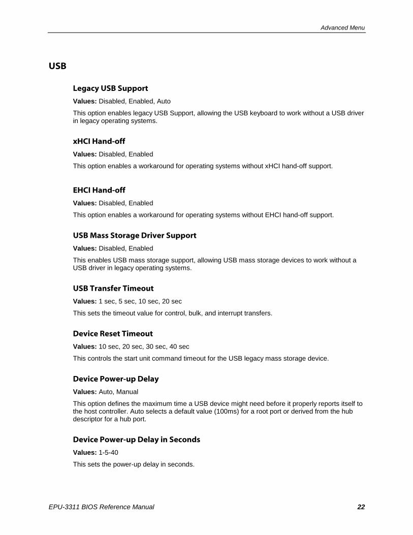
USB
Legacy USB Support
Values: Disabled, Enabled, Auto
This option enables legacy USB Support, allowing the USB keyboard to work without a USB driver in legacy operating systems.
xHCI Hand-off
Values: Disabled, Enabled
This option enables a workaround for operating systems without xHCI hand-off support.
EHCI Hand-off
Values: Disabled, Enabled
This option enables a workaround for operating systems without EHCI hand-off support.
USB Mass Storage Driver Support
Values: Disabled, Enabled
This enables USB mass storage support, allowing USB mass storage devices to work without a USB driver in legacy operating systems.
USB Transfer Timeout
Values: 1 sec, 5 sec, 10 sec, 20 sec
This sets the timeout value for control, bulk, and interrupt transfers.
Device Reset Timeout
Values: 10 sec, 20 sec, 30 sec, 40 sec
This controls the start unit command timeout for the USB legacy mass storage device.
Device Power-up Delay
Values: Auto, Manual
This option defines the maximum time a USB device might need before it properly reports itself to the host controller. Auto selects a default value (100ms) for a root port or derived from the hub descriptor for a hub port.
Device Power-up Delay in Seconds
Values: 1-5-40
This sets the power-up delay in seconds.

Advanced Menu
EPU-3311 BIOS Reference Manual 23
Mass Storage Devices
Values: Auto, Floppy, Forced FDD, Hard Disk, CD-ROM
This controls the USB mass storage device emulation.
Computing menu.
Security Configuration
TXE
Values: Disabled, Enabled
The Trusted Execution Engine is enabled here.
TXE HMRFPO
Values: Disabled, Enabled
This command enables Host ME Region Flash Protection Overwrite.
TXE Firmware Update
Values: Disabled, Enabled
This command enables TXE firmware update.
TXE EOP Message
Values: Disabled, Enabled
This option enables TXE End of Post Message.
Intel(R) AT
Values: Disabled, Enabled
Anti-theft Technology is enabled with this setting
Intel(R) AT Platform PBA
Values: Disabled, Enabled
Anti-Theft Platform Pre-boot Authentication can be enabled here.

Advanced Menu
EPU-3311 BIOS Reference Manual 24
Intel(R) AT Suspend Mode
Values: Disabled, Enabled
Anti-Theft Suspend Mode can be enabled here.
Intel(R) Ethernet Connection I210
NIC Configuration
Link Speed
Values: Auto Negotiated, 10 Mbps Half, 10 Mbps Full 100 Mbps Half, 100 Mbps Full
This setting specifies the port speed used for the selected boot protocol.
Wake on LAN
Values: Disabled, Enabled
Wake on LAN is enabled with this setting.
Blink LEDs
Values: 0-15
This enables Ethernet LEDs to blink for the specified time.
Driver Health
Intel(R) PRO/1000
Controller
This area displays the health status for the drivers/controllers.

EPU-3311 BIOS Reference Manual 25
Chipset Menu
North Bridge
Max TOLUD
Values: Dynamic, 2 GB, 2.25 GB, 2.5 GB, 2.75 GB, 3 GB
This will set the maximum value for top of addressable memory below the 4GB marker.
Aperture Size
Values: 128 MB, 256 MB, 512MB
This setting allocates the amount of RAM that assigned for internal graphics use.
PVAC
Values: Disabled, LITE Mode, SERPENT Mode
Protected Audio Video Control mode is enabled with this menu.
South Bridge
Azailia HD Audio
LPE Audio Support
Values: Disabled, LPE Audio PCI Mod, LPE Audio ACPI Mode
LPE Audio Support is set with this option.
Audio Controller
Values: Disabled, Enabled
This enables the audio controller.
Azailia Vci Enable
Values: Disabled, Enabled
This enables the Azailia Vci.
.
4

Chipset Menu
EPU-3311 BIOS Reference Manual 26
Azalia Docking Support Enable
Values: Disabled, Enabled
Azalia Docking Support enabled with this setting.
Azalia PME Enable
Values: Disabled, Enabled
Azalia PME is enabled with this setting.
Azalia HDMI Codec
Values: Disabled, Enabled
Azalia HDMI Codec is enabled with this setting.
HDMI Port B
Values: Disabled, Enabled
HDMI Port B audio is enabled with this setting.
HDMI Port C
Values: Disabled, Enabled
HDMI Port C audio is enabled with this setting.
USB
XHCI Mode
Values: Disabled, Enabled, Auto, Smart Auto
WARNING: Disabling XHCI without enabling EHCI at the same time will disable BIOS support for all USB devices, including the keyboard that is needed to enter BIOS Setup and revert changes.
This command USB3.0 mode support on USB0, USB1, USB2 and USB3 ports.
Enabled – USB ports will function correctly in BIOS but the ports on which the USB3.0 mode is enabled (see USB0 port USB3.0 item) will not function at all with the OS if the USB3.0 OS driver is not installed. USB ports will not function in pre-OS time if USB3.0 support in BIOS is disabled (see the USB3.0 Support in BIOS item).
Disabled – USB ports will function in USB2.0 mode only. No USB3.0 OS driver required. The USB ports will be routed to EHCI1 controller.
Auto – USB ports are initially set to operate in USB2.0 Mode and the USB3.0 OS driver (if available) will switch them to USB3.0 mode. If USB3.0 OS driver is not available, the ports will function correctly but will operate in USB2.0 mode.
Smart Auto – The BIOS will store the USB mode set by the OS and at next boot the BIOS will set this previously used mode. At G3 boot (first boot after mechanical disconnection of the power supply) the USB ports will function identically as in Auto mode. This mode is not available when 'Disabled' is selected at USB3.0 Support in BIOS item.

Chipset Menu
EPU-3311 BIOS Reference Manual 27
USB2 Link Power Management
Values: Disabled, Enabled
This option enables USB2 Link Power Management.
USB 2.0(EHCI) Support
Values: Disabled, Enabled
WARNING: Disabling EHCI without enabling XHCI at the same time will disable BIOS support for all USB devices, including the keyboard that is needed to enter BIOS Setup and revert changes.
This setting enables the control of USB EHCI (USB 2.0) functions.
USB Per Port Control
Values: Disabled, Enabled
This setting enables the control of each of the USB ports (0-3).
USB Port 0
Values: Disabled, Enabled
This setting enables Port 0.
USB Port 1
Values: Disabled, Enabled
This setting enables Port 1.
USB Port 2
Values: Disabled, Enabled
This setting enables Port 2.
USB Port 3
Values: Disabled, Enabled
This setting enables Port 3.
PCI Express Configuration
PCIe noncompliance Card
Values: Not Supported, Supported
This option enables PCIe 1.0 Device Support.

Chipset Menu
EPU-3311 BIOS Reference Manual 28
PCI Express Port 0 – 3
Values: Disabled, Enabled
This setting enables the selected PCIe Port.
Hot Plug
Values: Disabled, Enabled
This enables or disables PCI Express* Hot Plug support.
Speed
Values: Auto, Gen 2, Gen 1
This setting configures PCIe Port speed. (This only appears when the PCIe noncompliance Card option is set to “Not Supported”. If PCIe noncompliance Card is set to “Supported”, the default speed is Gen1.)
Extra Bus Reserved
Values: 0-7
This sets the number of reserved bridges needed if a device is hot plugged.
Reserved Memory
Values: 10
0-20
This sets the reserved memory range for this Root Bridge.
Reserved Memory Alignment
Values: 1
0-31
This sets the reserved memory alignment.
Prefetchable Memory
Values: 10
0-20
This sets the prefetchable memory range for this Root Bridge.
Prefetchable Memory Alignment
Values: 1
0-31
This sets the prefetchable memory alignment in bits.

Chipset Menu
EPU-3311 BIOS Reference Manual 29
Reserved I/O
Values: 4
0-20
This sets the Reserved I/O range in kilobytes for this Root Bridge.

EPU-3311 BIOS Reference Manual 30
Security Menu
Security Settings
BIOS Password
Values: Type in the password
This will set the BIOS password of 3 to 20 characters. A known password can be cleared by setting a blank password.
HDD Security Configuration
Set User Password
Values:
A hard drive password is set with this option.
Secure Boot Menu
Secure Boot
Values: Disabled, Enabled
This enables the system to boot in Secure Boot Mode.
Secure Boot Mode
Values: Standard, Custom
This command sets the secure boot mode. The Standard option only allows industry standard keys to be used for validating images prior to execution. The Custom option allows users to modify (Delete, Append or Set) the keys used to validate images before executing them.
Key Management
Default Key Provision
Values: Disabled, Enabled
This menu option installs the factory default keys for PK, KEK, DB, DBT and DBX variables.
5

Security Menu
EPU-3311 BIOS Reference Manual 31
.
Delete All Secure Boot Variables
Values: Select
This selection deletes all keys from the PK, KEK, DB, DBT and DBX variables.
Enroll All Factory Default Keys
Values: Select
This menu item enrolls all factory keys from the PK, KEK, DB, DBT and DBX variables.
.
Save All Secure Boot Variables
Values: Select
This selection will export of all the Secure Boot variable keys to external fat formatted media. This item can be used to examine the keys installed on a system.
Platform Key
Delete PK
Values: Select
When selected, this option will delete the currently installed PK key.
Set New PK
Values: Select
This selection will allow a user to set a replacement PK key.
Key Exchange Key
Delete KEK
Values: Select
When selected, this option will delete the currently installed KEK keys.
Set New KEK
Values: Select
This selection will allow a user to set a replacement KEK key.

Security Menu
EPU-3311 BIOS Reference Manual 32
Append KEK
Values: Select
This selection will allow a user to append an additional KEK key to the current keys.
Authorized Signatures
Delete DB
Values: Select
When selected, this option will delete the currently installed DB keys.
Set New DB
Values: Select
This selection will allow a user to set a replacement DB key.
Append DB
Values: Select
This selection will allow a user to append an additional DB key to the current keys.
Authorized Timestamps
Delete DBT
Values: Select
When selected, this option will delete the currently installed DBT keys.
Set New DBT
Values: Select
This selection will allow a user to set a replacement DBT key.
Append DBT
Values: Select
This selection will allow a user to append an additional DBT key to the current keys.

Security Menu
EPU-3311 BIOS Reference Manual 33
Forbidden Signatures
Delete DBX
Values: Select
When selected, this option will delete the currently installed DBX keys.
Set New DBX
Values: Select
This selection will allow a user to set a replacement DBX key.
Append DBX
Values: Select
This selection will allow a user to append an additional DBX key to the current keys.

EPU-3311 BIOS Reference Manual 34
Boot Setup Configuration Menu
Boot Setup Configuration
Setup Prompt Timeout
Values: 1
0 - 65535
This command will set the number of seconds to wait for a setup activation key.
0 results in no waiting time (not recommended), 65535 will wait indefinitely.
Bootup NumLock State
Values: On, Off
This setting controls the state of the Numlock key at startup.
Quiet Boot
Values: Disabled, Enabled
The disabled option results in the normal POST messages being displayed. Enabled permits an OEM logo to appear rather that POST messages.
Enter Setup If No Boot Device
Values: No, Yes
This setting controls having a setup menu appear when no boot devices are found.
Enable Popup Boot Menu
Values: No, Yes
This command determines whether a popup boot menu appears when F11 is pressed.
Boot Priority Selection
Values: Device Based, Type Based
This setting allows for an option between device and type based boot priority lists. The “Device Based” boot priority list provides a list of currently detected devices. The “Type Based” boot priority list shows device types, even if a respective device is not yet present. The “Device Based” boot priority list might change dynamically when devices are physically removed or added to the system. The “Type Based” boot menu is static and can only be changed manually.
6

Boot Setup Configuration Menu
EPU-3311 BIOS Reference Manual 35
Power Loss Control
Values: Remain Off, Turn On. Last State
Power Loss Control specifies the mode of operation if an AC power loss occurs. Remain Off keeps the power off until the power button is pressed. Turn On restores power to the computer. Last State restores the previous power state before power loss occurred.
AT Shutdown Mode
Values: On, Off
This setting determines the behavior of AT powered systems after shutdown.
Battery Support
Values: Auto (Battery Manager), Battery-Only on I2C Bus, Battery-Only on SMbus
This menu item selects the battery system support. Select the “Battery-Only on I2C Bus’ option for battery-only systems using an I
2C bus. Select the “Battery-Only on SMBus’ option for battery only
systems using SMBus. Select “Auto” for systems equipped with a real battery system manager (connected via I
2C or SMBus).
System Off Mode
Values: G3/Mech Off, S5/Soft Off
System Off Mode determines the system state for battery systems after shutdown.
Fast Boot
Values: Disabled, Enabled
The enabled option results in a boot with a minimal set of devices required for launch.

EPU-3311 BIOS Reference Manual 36
Save & Exit Menu
Save Changes and Exit
This item saves changes to the system and exits the setup menu.
Discard Changes and Exit
This option exits the setup menu without saving any changes.
Save Changes and Reset
This option saves changes and resets the system.
Discard Changes and Reset
This option will reset the system without any changes being saved.
Save Options
Save Changes
Save Changes will save any changes without leaving the setup menu.
Discard Change
This selection discards changes without leaving the setup menu.
Restore Defaults
This selection restores the default values for the setup menu.
7