epsilon > rh glider electric door system for ... procedure all tests should be undertaken with...
TRANSCRIPT
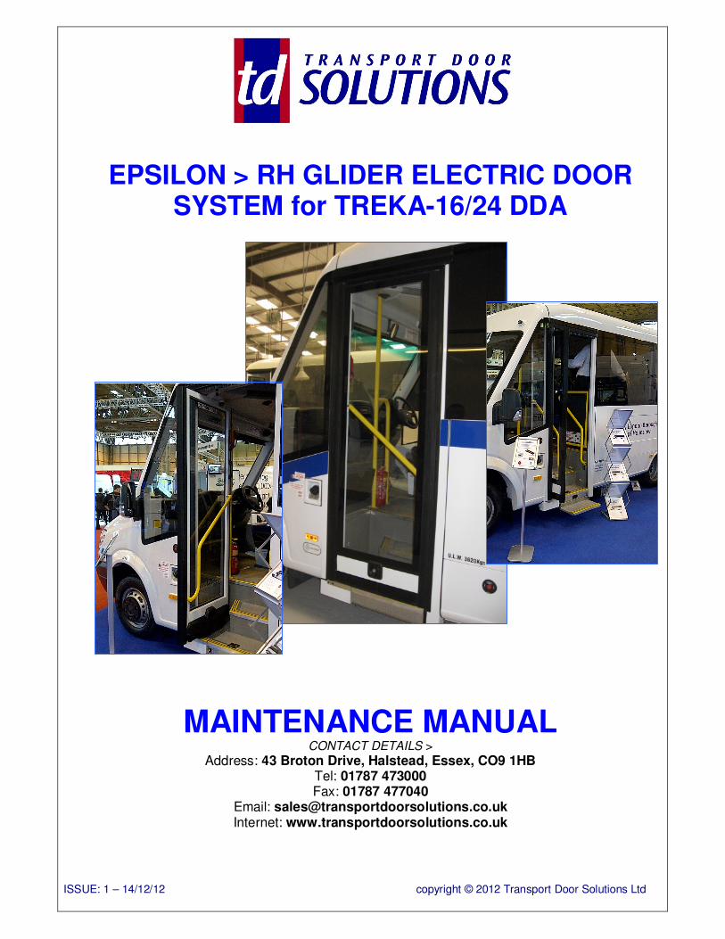
EPSILON > RH GLIDER ELECTRIC DOOR SYSTEM for TREKA-16/24 DDA
MAINTENANCE MANUAL CONTACT DETAILS >
Address: 43 Broton Drive, Halstead, Essex, CO9 1HB Tel: 01787 473000 Fax: 01787 477040
Email: [email protected] Internet: www.transportdoorsolutions.co.uk
ISSUE: 1 – 14/12/12 copyright © 2012 Transport Door Solutions Ltd
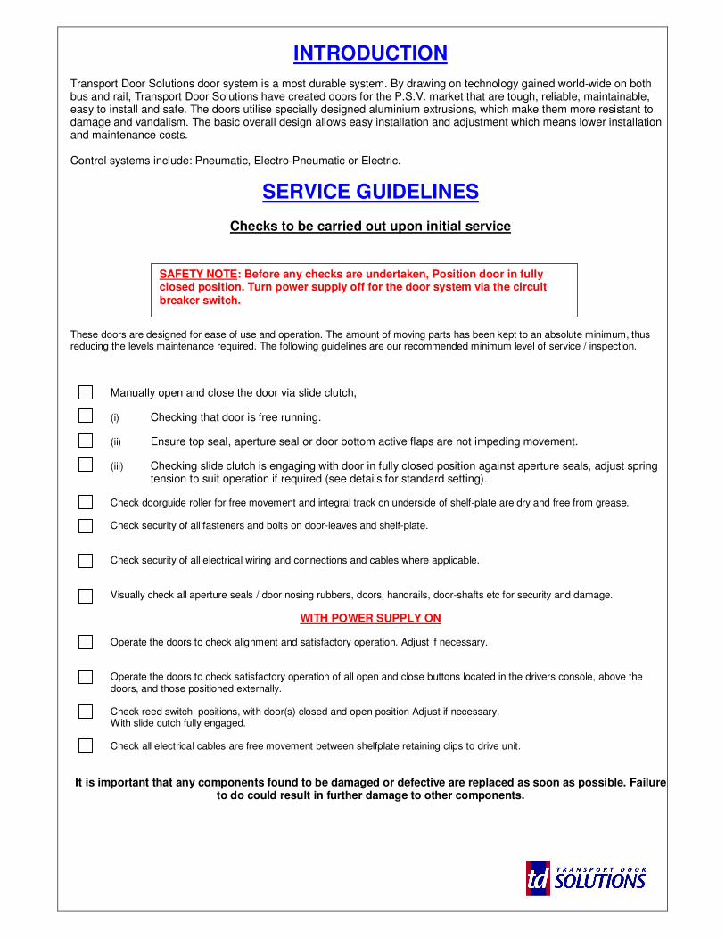
INTRODUCTION
Transport Door Solutions door system is a most durable system. By drawing on technology gained world-wide on both bus and rail, Transport Door Solutions have created doors for the P.S.V. market that are tough, reliable, maintainable, easy to install and safe. The doors utilise specially designed aluminium extrusions, which make them more resistant to damage and vandalism. The basic overall design allows easy installation and adjustment which means lower installation and maintenance costs. Control systems include: Pneumatic, Electro-Pneumatic or Electric.
SERVICE GUIDELINES
Checks to be carried out upon initial service
These doors are designed for ease of use and operation. The amount of moving parts has been kept to an absolute minimum, thus reducing the levels maintenance required. The following guidelines are our recommended minimum level of service / inspection.
Manually open and close the door via slide clutch,
(i) Checking that door is free running.
(ii) Ensure top seal, aperture seal or door bottom active flaps are not impeding movement.
(iii) Checking slide clutch is engaging with door in fully closed position against aperture seals, adjust spring tension to suit operation if required (see details for standard setting).
Check doorguide roller for free movement and integral track on underside of shelf-plate are dry and free from grease. Check security of all fasteners and bolts on door-leaves and shelf-plate.
Check security of all electrical wiring and connections and cables where applicable. Visually check all aperture seals / door nosing rubbers, doors, handrails, door-shafts etc for security and damage.
WITH POWER SUPPLY ON Operate the doors to check alignment and satisfactory operation. Adjust if necessary. Operate the doors to check satisfactory operation of all open and close buttons located in the drivers console, above the doors, and those positioned externally. Check reed switch positions, with door(s) closed and open position Adjust if necessary, With slide cutch fully engaged.
Check all electrical cables are free movement between shelfplate retaining clips to drive unit.
It is important that any components found to be damaged or defective are replaced as soon as possible. Failure
to do could result in further damage to other components.
SAFETY NOTE: Before any checks are undertaken, Position door in fully closed position. Turn power supply off for the door system via the circuit breaker switch.
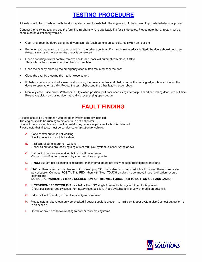
TESTING PROCEDURE All tests should be undertaken with the door system correctly installed. The engine should be running to provide full electrical power Conduct the following test and use the fault-finding charts where applicable if a fault is detected. Please note that all tests must be conducted on a stationary vehicle. • Open and close the doors using the drivers controls (push buttons on console, footswitch on floor etc)
• Remove handbrake and try to open doors from the drivers controls. If a handbrake interlock is fitted, the doors should not open. Re-apply the handbrake when the check is completed.
• Open door using drivers control, remove handbrake, door will automatically close, if fitted Re-apply the handbrake when the check is completed.
• Open the door by pressing the emergency open button mounted near the door. • Close the door by pressing the interior close button. • If obstacle detection is fitted, close the door using the drivers control and obstruct on of the leading edge rubbers. Confirm the
doors re-open automatically. Repeat the test, obstructing the other leading edge rubber. • Manually check slide cutch. With door in fully closed position, pull door open using internal pull hand or pushing door from out side.
Re-engage clutch by closing door manually or by pressing open button
FAULT FINDING All tests should be undertaken with the door system correctly installed. The engine should be running to provide full electrical power. Conduct the following test and use the fault-finding where applicable if a fault is detected. Please note that all tests must be conducted on a stationary vehicle.
A. If one control button is not working:- Check continuity of switch & cables B. If all control buttons are not working:- Check all buttons are receiving single from muti-plex system. & check “A” as above C. If all control buttons are working but door will not operate.
Check to see if motor is running by sound or vibration (touch)
D. If YES:-But ram not extending or retracting, then internal gears are faulty, request replacement drive unit.
E. If NO :- Then motor can be checked. Disconnect plug “5” Short cable from motor red & black connect these to separate power supply. Connect “POSITIVE” to RED . then with “Neg, TOUCH on black if door move in wrong direction reverse connections DO NOT PERMANENTLY MAKE CONNECTION AS THIS WILL FORCE RAM TO BOTTOM OUT AND JAM UP
F. If YES FROM “E” MOTOR IS RUNNING :- Then NO single from mult-plex system to motor is present. Check position of reed switches. For factory reset position, Reed switches to line up with marks on drive unit G. If door still not operating:- Then Service Agent is required
H. Please note all above can only be checked if power supply is present to mult-plex & door system also Door cut out switch is
in on position
I. Check for any fuses blown relating to door or multi-plex systems
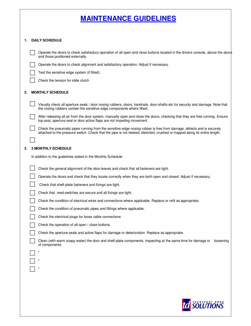
MAINTENANCE GUIDELINES
1. DAILY SCHEDULE
Operate the doors to check satisfactory operation of all open and close buttons located in the drivers console, above the doors and those positioned externally.
Operate the doors to check alignment and satisfactory operation. Adjust if necessary.
Test the sensitive edge system (if fitted). Check the tension for slide clutch
2. MONTHLY SCHEDULE
Visually check all aperture seals / door nosing rubbers, doors, handrails, door-shafts etc for security and damage. Note that the nosing rubbers contain the sensitive edge components where fitted. After releasing all air from the door system, manually open and close the doors, checking that they are free running. Ensure top seal, aperture seal or door active flaps are not impeding movement. Check the pneumatic pipes running from the sensitive edge nosing rubber is free from damage, defects and is securely attached to the pressure switch. Check that the pipe is not twisted, distorted, crushed or trapped along its entire length.
3. 3 MONTHLY SCHEDULE
In addition to the guidelines stated in the Monthly Schedule:
Check the general alignment of the door-leaves and check that all fasteners are tight. Operate the doors and check that they locate correctly when they are both open and closed. Adjust if necessary. Check that shelf-plate fasteners and fixings are tight. Check that reed-switches are secure and all fixings are tight. Check the condition of electrical wires and connections where applicable. Replace or refit as appropriate. Check the condition of pneumatic pipes and fittings where applicable. Check the electrical plugs for loose cable connections Check the operation of all open / close buttons. Check the aperture seals and active flaps for damage or deterioration. Replace as appropriate. Clean (with warm soapy water) the door and shelf-plate components, inspecting at the same time for damage or loosening of components. * * *
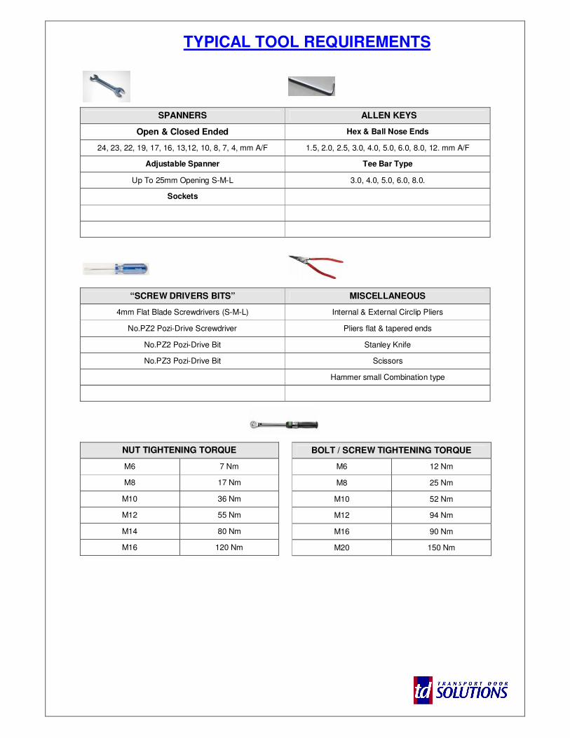
TYPICAL TOOL REQUIREMENTS
SPANNERS ALLEN KEYS
Open & Closed Ended Hex & Ball Nose Ends
24, 23, 22, 19, 17, 16, 13,12, 10, 8, 7, 4, mm A/F 1.5, 2.0, 2.5, 3.0, 4.0, 5.0, 6.0, 8.0, 12. mm A/F
Adjustable Spanner Tee Bar Type
Up To 25mm Opening S-M-L 3.0, 4.0, 5.0, 6.0, 8.0.
Sockets
“SCREW DRIVERS BITS” MISCELLANEOUS
4mm Flat Blade Screwdrivers (S-M-L) Internal & External Circlip Pliers
No.PZ2 Pozi-Drive Screwdriver Pliers flat & tapered ends
No.PZ2 Pozi-Drive Bit Stanley Knife
No.PZ3 Pozi-Drive Bit Scissors
Hammer small Combination type
NUT TIGHTENING TORQUE
M6 7 Nm
M8 17 Nm
M10 36 Nm
M12 55 Nm
M14 80 Nm
M16 120 Nm
BOLT / SCREW TIGHTENING TORQUE
M6 12 Nm
M8 25 Nm
M10 52 Nm
M12 94 Nm
M16 90 Nm
M20 150 Nm
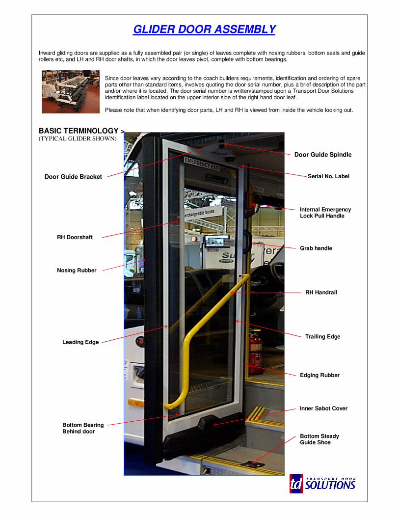
GLIDER DOOR ASSEMBLY
Inward gliding doors are supplied as a fully assembled pair (or single) of leaves complete with nosing rubbers, bottom seals and guide rollers etc, and LH and RH door shafts, in which the door leaves pivot, complete with bottom bearings.
Since door leaves vary according to the coach builders requirements, identification and ordering of spare parts other than standard items, involves quoting the door serial number, plus a brief description of the part and/or where it is located. The door serial number is written/stamped upon a Transport Door Solutions identification label located on the upper interior side of the right hand door leaf. Please note that when identifying door parts, LH and RH is viewed from inside the vehicle looking out.
BASIC TERMINOLOGY > (TYPICAL GLIDER SHOWN)
RH Handrail
Grab handle
RH Doorshaft
Door Guide Bracket Serial No. Label
(b)
Nosing Rubber
Bottom Bearing Behind door
Door Guide Spindle
Inner Sabot Cover
Edging Rubber
Internal Emergency Lock Pull Handle
Leading Edge Trailing Edge
Bottom Steady Guide Shoe
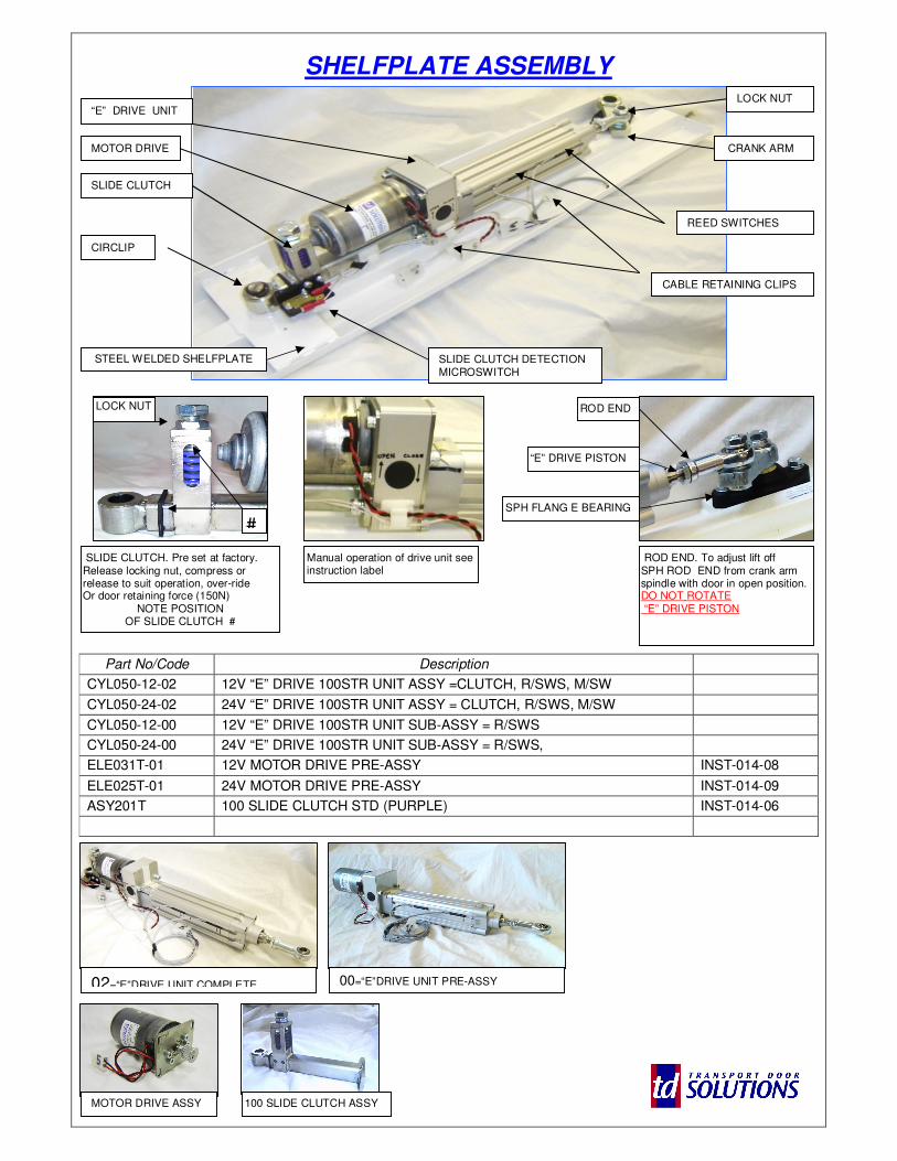
SHELFPLATE ASSEMBLY
Part No/Code Description
CYL050-12-02 12V “E” DRIVE 100STR UNIT ASSY =CLUTCH, R/SWS, M/SW
CYL050-24-02 24V “E” DRIVE 100STR UNIT ASSY = CLUTCH, R/SWS, M/SW
CYL050-12-00 12V “E” DRIVE 100STR UNIT SUB-ASSY = R/SWS
CYL050-24-00 24V “E” DRIVE 100STR UNIT SUB-ASSY = R/SWS,
ELE031T-01 12V MOTOR DRIVE PRE-ASSY INST-014-08
ELE025T-01 24V MOTOR DRIVE PRE-ASSY INST-014-09
ASY201T 100 SLIDE CLUTCH STD (PURPLE) INST-014-06
“E” DRIVE UNIT
STEEL WELDED SHELFPLATE
SLIDE CLUTCH
ROD END
MOTOR DRIVE
REED SWITCHES
ROD END. To adjust lift off SPH ROD END from crank arm spindle with door in open position. DO NOT ROTATE “E” DRIVE PISTON
SLIDE CLUTCH. Pre set at factory. Release locking nut, compress or release to suit operation, over-ride Or door retaining force (150N)
NOTE POSITION OF SLIDE CLUTCH #
#
CIRCLIP
CRANK ARM
SLIDE CLUTCH DETECTION MICROSWITCH
CABLE RETAINING CLIPS
“E” DRIVE PISTON
LOCK NUT
LOCK NUT
SPH FLANG E BEARING
MOTOR DRIVE ASSY 100 SLIDE CLUTCH ASSY
Manual operation of drive unit see instruction label
02=“E”DRIVE UNIT COMPLETE 00=“E”DRIVE UNIT PRE-ASSY
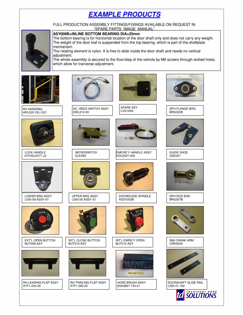
EXAMPLE PRODUCTS
FULL PRODUCTION ASSEMBLY FITTINGS/FIXINGS AVAILABLE ON REQUEST IN “SPARE PARTS IMAGE MANUAL”
ASY006B=INLINE BOTTOM BEARING DIA=25mm The bottom bearing is for horizontal location of the door shaft only and does not carry any weight. The weight of the door leaf is suspended from the top bearing, which is part of the shelfplate mechanism. The rotating element is nylon. It is free to slide inside the door shaft and needs no vertical adjustment. The whole assembly is secured to the floor/step of the vehicle by M6 screws through slotted holes, which allow for tranverse adjustment.
NC. REED SWITCH ASSY EWL212-00
SPH FLANGE BRG BRG022B
DOORGUIDE SPINDLE ASSY003B
MICROSWITCH ELE099
EMERG’Y HANDLE ASSY HDL003T-002
GUIDE SHOE GDE001
LOWER BRG ASSY L500-09-ASSY-01
UPPER BRG ASSY L500-05-ASSY-01
LOCK HANDLE KITHDL007T-J2
INT’L EMRG’Y OPEN BUT012-ASY
INT’L CLOSE BUTTON BUT010-ASY
EXT’L OPEN BUTTON BUT009-ASY
SPH ROD END BRG007B
R66 CRANK ARM CRK002A
RH HANDRAIL HRL025-YEL1021
RH LEADING FLAP ASSY ATF1-244-25
RH TRAILING FLAP ASSY ATF1-380-25
HORZ BRUSH ASSY BSA3807-740-01
SPARE KEY LCK100A
DOORSHAFT SLIDE RAIL L500-51-192
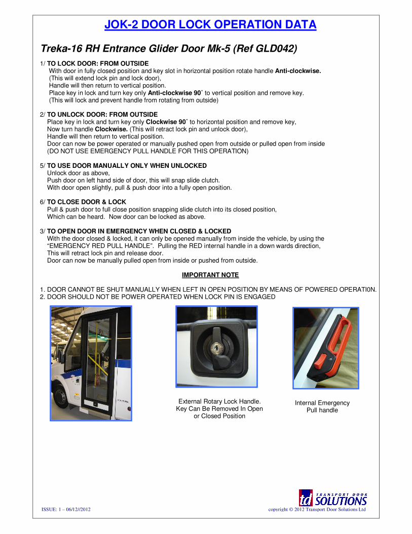
JOK-2 DOOR LOCK OPERATION DATA
Treka-16 RH Entrance Glider Door Mk-5 (Ref GLD042)
1/ TO LOCK DOOR: FROM OUTSIDE With door in fully closed position and key slot in horizontal position rotate handle Anti-clockwise. (This will extend lock pin and lock door), Handle will then return to vertical position. Place key in lock and turn key only Anti-clockwise 90˚ to vertical position and remove key. (This will lock and prevent handle from rotating from outside) 2/ TO UNLOCK DOOR: FROM OUTSIDE Place key in lock and turn key only Clockwise 90˚ to horizontal position and remove key, Now turn handle Clockwise. (This will retract lock pin and unlock door), Handle will then return to vertical position. Door can now be power operated or manually pushed open from outside or pulled open from inside (DO NOT USE EMERGENCY PULL HANDLE FOR THIS OPERATION) 5/ TO USE DOOR MANUALLY ONLY WHEN UNLOCKED Unlock door as above, Push door on left hand side of door, this will snap slide clutch. With door open slightly, pull & push door into a fully open position. 6/ TO CLOSE DOOR & LOCK Pull & push door to full close position snapping slide clutch into its closed position, Which can be heard. Now door can be locked as above.
3/ TO OPEN DOOR IN EMERGENCY WHEN CLOSED & LOCKED With the door closed & locked, it can only be opened manually from inside the vehicle, by using the “EMERGENCY RED PULL HANDLE”. Pulling the RED internal handle in a down wards direction, This will retract lock pin and release door. Door can now be manually pulled open from inside or pushed from outside.
IMPORTANT NOTE
1. DOOR CANNOT BE SHUT MANUALLY WHEN LEFT IN OPEN POSITION BY MEANS OF POWERED OPERATI0N. 2. DOOR SHOULD NOT BE POWER OPERATED WHEN LOCK PIN IS ENGAGED
Internal Emergency Pull handle
External Rotary Lock Handle. Key Can Be Removed In Open
or Closed Position
ISSUE: 1 – 06/12//2012 copyright © 2012 Transport Door Solutions Ltd
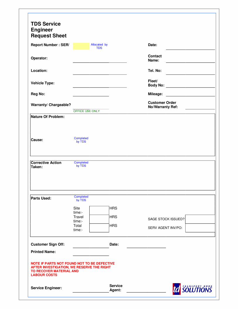
TDS Service Engineer Request Sheet
Report Number : SER/ Allocated by
TDS Date:
Operator: Contact
Name:
Location: Tel. No:
Vehicle Type: Fleet/
Body No:
Reg No: Mileage:
Warranty/ Chargeable? Customer Order
No/Warranty Ref:
OFFICE USE ONLY
Nature Of Problem:
Cause: Completed
by TDS
Corrective Action Taken:
Completed by TDS
Parts Used: Completed
by TDS
Site time:-
HRS
Travel time:-
HRS SAGE STOCK ISSUED?
Total time:-
HRS SERV AGENT INV/PO:
Customer Sign Off: Date:
Printed Name:
NOTE IF PARTS NOT FOUND NOT TO BE DEFECTIVE AFTER INVESTIGATION, WE RESERVE THE RIGHT
TO RECOVER MATERIAL AND LABOUR COSTS
Service Engineer: Service Agent:

SHEET FOR NOTES/COMMENTS > (INTENTIONALLY BLANK)
ISSUE: 1 – 06/12//2 copyright © 2012 Transport Door Solutions Ltd
The images in this document are the property of transport door solutions ltd and must not be copied or reproduced without written permission