epc project interdepency and work flow- promo
TRANSCRIPT
EPC Project Interdependency
and
Work Flow

Our Belief
Now Everyone Can Be Trained

Table Of Contents
Topic Page
Introduction to EPC Project Management 5
EPC Project Management work flow 13
Engineering Document Issuance Purpose 19
Engineering Work Flow 21
Procurement work flow 43
On Shore Project Schedule and Schedule dependency 46
Work Front Concept 48
Advance Work Packaging 52
Sample WBS 65
Piping Engineering as case study 73
Vessel Fabrication Work flow as case study 83
3

4
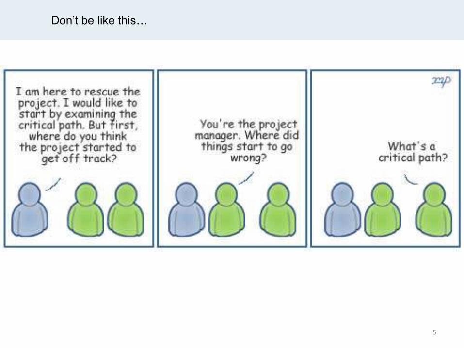
Don’t be like this…
5

EPC Project Management
- Introduction
6
EPC Project Management
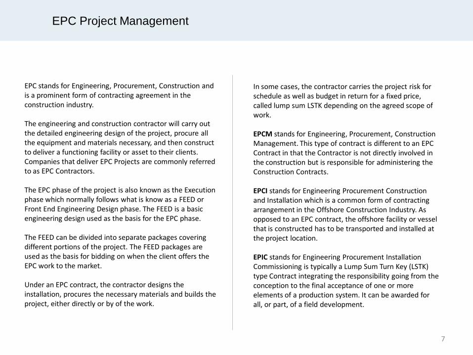
EPC stands for Engineering, Procurement, Construction and is a prominent form of contracting agreement in the construction industry. The engineering and construction contractor will carry out the detailed engineering design of the project, procure all the equipment and materials necessary, and then construct to deliver a functioning facility or asset to their clients. Companies that deliver EPC Projects are commonly referred to as EPC Contractors. The EPC phase of the project is also known as the Execution phase which normally follows what is know as a FEED or Front End Engineering Design phase. The FEED is a basic engineering design used as the basis for the EPC phase. The FEED can be divided into separate packages covering different portions of the project. The FEED packages are used as the basis for bidding on when the client offers the EPC work to the market. Under an EPC contract, the contractor designs the installation, procures the necessary materials and builds the project, either directly or by of the work.
In some cases, the contractor carries the project risk for schedule as well as budget in return for a fixed price, called lump sum LSTK depending on the agreed scope of work. EPCM stands for Engineering, Procurement, Construction Management. This type of contract is different to an EPC Contract in that the Contractor is not directly involved in the construction but is responsible for administering the Construction Contracts. EPCI stands for Engineering Procurement Construction and Installation which is a common form of contracting arrangement in the Offshore Construction Industry. As opposed to an EPC contract, the offshore facility or vessel that is constructed has to be transported and installed at the project location. EPIC stands for Engineering Procurement Installation Commissioning is typically a Lump Sum Turn Key (LSTK) type Contract integrating the responsibility going from the conception to the final acceptance of one or more elements of a production system. It can be awarded for all, or part, of a field development.
7


EPC Project Organization
9

Design Procurement Manufacturing/
Fabrication Shipment
Installation Construction &
Erection Inspection & FAT Hand-Over
10

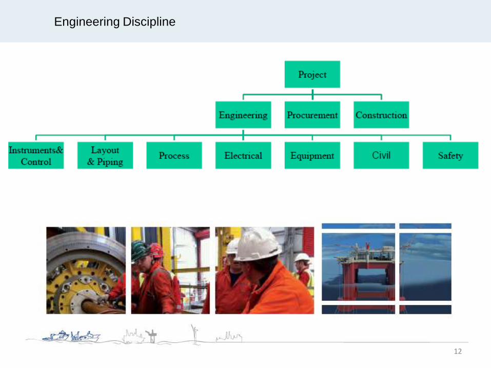
Engineering Discipline
12

EPC Project Management
- Work Flow
13
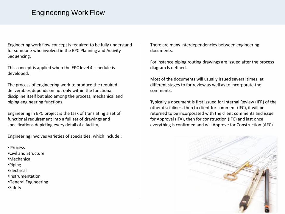
Engineering work flow concept is required to be fully understand for someone who involved in the EPC Planning and Activity Sequencing. This concept is applied when the EPC level 4 schedule is developed. The process of engineering work to produce the required deliverables depends on not only within the functional discipline itself but also among the process, mechanical and piping engineering functions. Engineering in EPC project is the task of translating a set of functional requirement into a full set of drawings and specifications depicting every detail of a facility, Engineering involves varieties of specialties, which include : • Process •Civil and Structure •Mechanical •Piping •Electrical •Instrumentation •General Engineering •Safety
Engineering Work Flow
There are many interdependencies between engineering documents. For instance piping routing drawings are issued after the process diagram Is defined. Most of the documents will usually issued several times, at different stages to for review as well as to incorporate the comments. Typically a document is first issued for Internal Review (IFR) of the other disciplines, then to client for comment (IFC), it will be returned to be incorporated with the client comments and issue for Approval (IFA), then for construction (IFC) and last once everything is confirmed and will Approve for Construction (AFC)
14

The entire strategy is dependent on Engineering and Procurement providing their deliverables to meet Path of Construction. Contractor mobilizes based on Engineering forecast of IFC EWPs (Engineering Work Packages).
15

Engineering Work Flow
Engineering Disciplines
Activity Process Civil and Structure
Mechanical Piping Electrical Instrumentation
Diagrams
Geographical Drawing
Architecture Drawing
Calculations
Equipment or material spec, data sheet & requisition
Site work spec
Engineering phase is very much concerned with documentation.
16

From Sequential To Concurrent Execution
Engineering Procurement Construction
Engineering
Procurement
Construction
17

Project Execution
The Past: sequential execution
The Present: concurrent execution
18

EPC Project Management
- Engineering Document Issue Purposes
19
Issuing Purpose
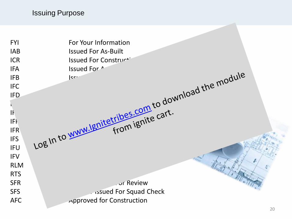
FYI For Your Information IAB Issued For As-Built ICR Issued For Construction Record IFA Issued For Approval IFB Issued For Bid IFC Issued For Construction IFD Issued For Design IFE Issued For Estimate IFH Issued For Hazop IFP Issued For Purchase IFR Issued For Review IFS Issued For Squad Check IFU Issued For Use IFV Issued For Void RLM Red Line Mark-up RTS Return To Supplier SFR Supplier Issued For Review SFS Supplier Issued For Squad Check AFC Approved for Construction
20

EPC Project Management
- Engineering Work Flow
21
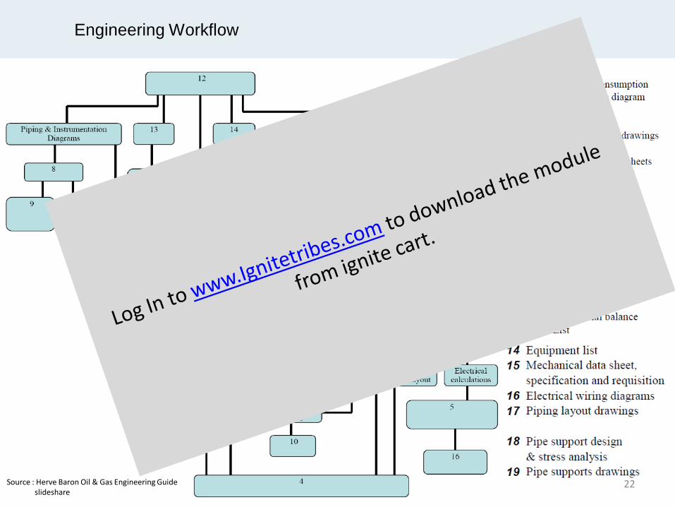
Engineering Workflow
22 Source : Herve Baron Oil & Gas Engineering Guide slideshare

Engineering Workflow
23 Source : Herve Baron Oil & Gas Engineering Guide slideshare
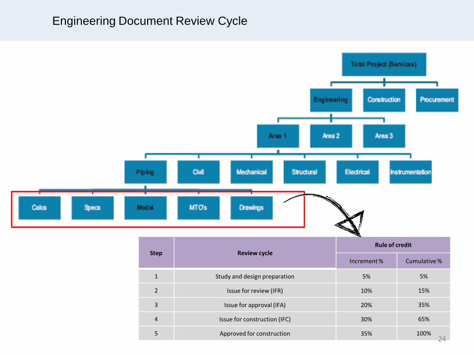
Engineering Document Review Cycle
Step Review cycle Rule of credit
Increment % Cumulative %
1 Study and design preparation 5% 5%
2 Issue for review (IFR) 10% 15%
3 Issue for approval (IFA) 20% 35%
4 Issue for construction (IFC) 30% 65%
5 Approved for construction 35% 100% 24
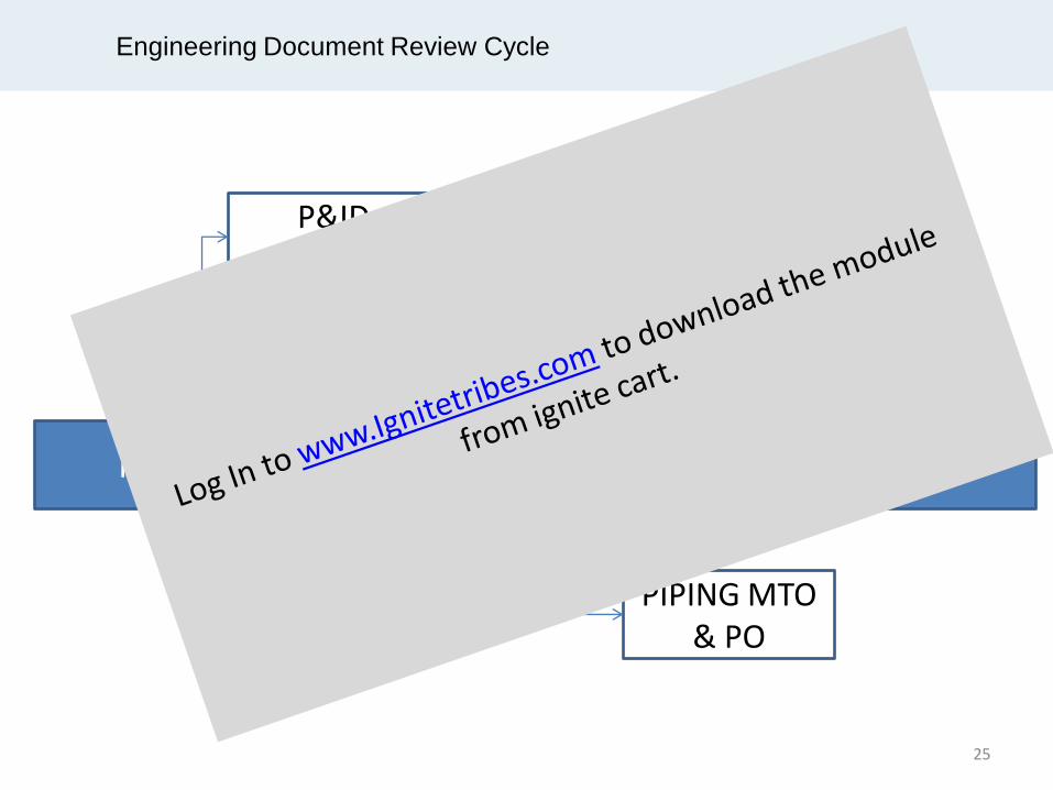
Engineering Document Review Cycle
IFR IFA IFC
P&ID REVIEW
HAZOP
PIPING MTO & PO
25
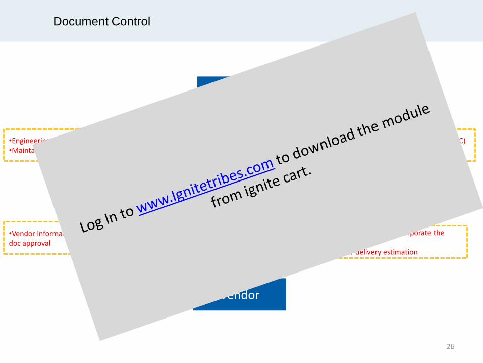
Document Control
Engineering
Client
Vendor
Documents submitted to client
Approval/ Comments
Documents submission Comments
•Client Review cycle. (IFR,IFA,IFC,AFC) •Client Review duration
•Engineering submission cut-off •Maintain internal and external baseline
•Vendor information criticality for client doc approval
•Vendor duration to incorporate the comments •Vendor delivery estimation
26

Vendor Data
Engineering is the integrator of the Plant equipment, and is highly dependent on vendor data
27

Engineering Work Flow – Process Design
Process Design
PFDs H&M balance
P&IDs
Process data sheet
Equipment specification
Vendor drawings
Rotating Pressure vessels Heat exchangers Fired equipment Packages etc.
Layout Civil Electrical
Piping
Instrumentation
28
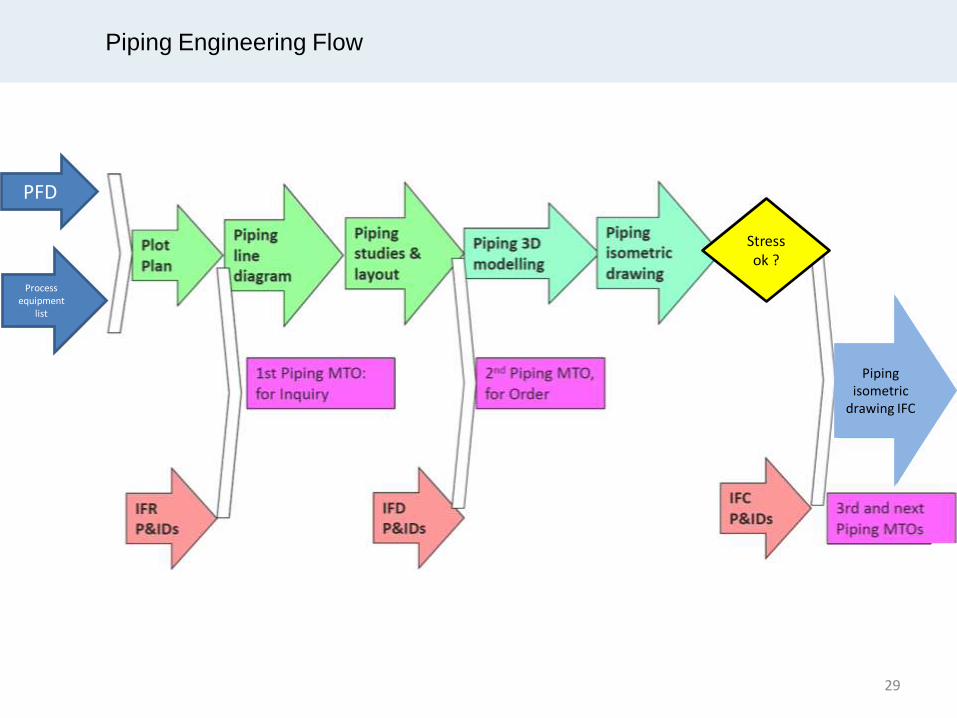
Piping Engineering Flow
PFD
Process equipment
list
Piping isometric
drawing IFC
Stress ok ?
29

3D
Modeling
(General)
1st Model review
2nd model review
3rd model review
3D
Mo
de
l
30

3D
Modeling
(Skid
Project)
1st Model review (30%)
2nd model review (60%)
3rd model review (90%)
3D
Mo
de
l
IFA pipe support dwg
IFA pipe GA dwg
IFA piping plan dwg
IFA structural GA
IFA tubing routing layout
IFI pipe ISO
IFA Instrument cable routing layout
IFA instrument cable trench &tray layout
IFA Instrument location
IFA Skid Tie-in report
IFA General structural deflection
& stress analysis report
IFA Structural GA dwg
IFC Instrument location dwg
IFC pipe GA dwg
Piping Materials
P&IDs 1st issue
Plot plan
IFD P&IDs
E&I main cable routing
First equipment vendor dwg
IFC piping ISO
Final piping MTO
31
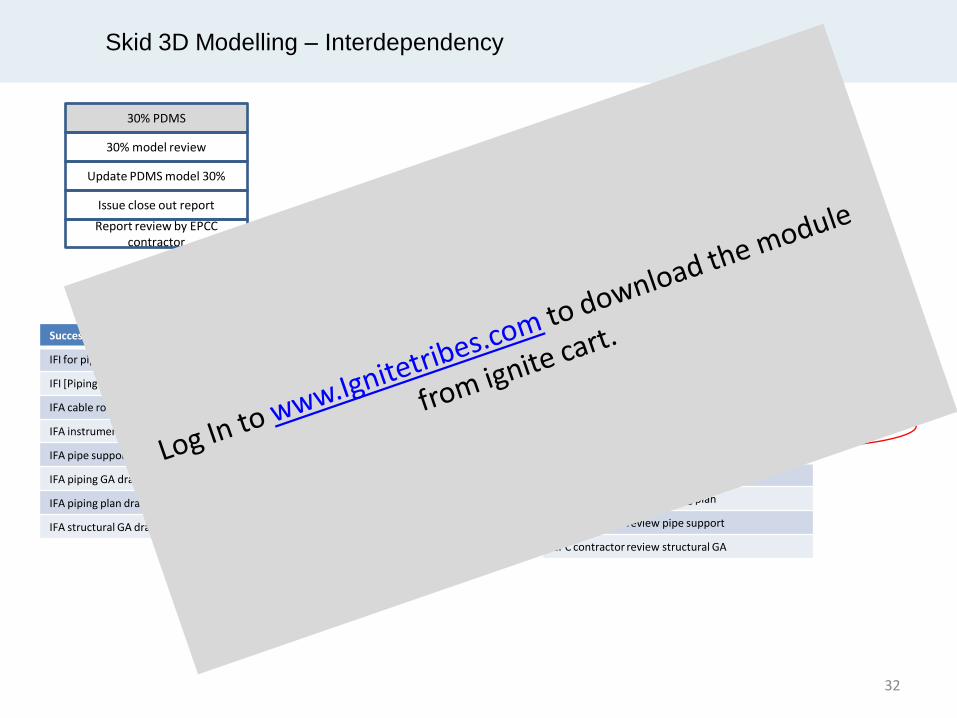
Skid 3D Modelling – Interdependency
30% PDMS
30% model review
Update PDMS model 30%
Issue close out report
Report review by EPCC contractor
60% PDMS
60% model review
Update PDMS model 60%
Issue close out report
90% PDMS
90% model review
Update PDMS model 90%
Issue close out 90% report
Report review by EPC contractor
Receive final comment from EPC contractor
Successor for 60% PDMS (issue close out report)
IFI for piping ISO
IFI [Piping Isometric]
IFA cable routing layout
IFA instrumentation location
IFA pipe support drawing
IFA piping GA drawing
IFA piping plan drawing
IFA structural GA drawing
Successor for 90% PDMS (issue close out report)
EPC contractor review piping GA
EPC contractor review piping plan
EPC contractor review pipe support
EPC contractor review structural GA
32
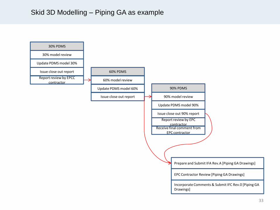
Skid 3D Modelling – Piping GA as example
30% PDMS
30% model review
Update PDMS model 30%
Issue close out report
Report review by EPCC contractor
60% PDMS
60% model review
Update PDMS model 60%
Issue close out report
90% PDMS
90% model review
Update PDMS model 90%
Issue close out 90% report
Report review by EPC contractor
Receive final comment from EPC contractor
Prepare and Submit IFA Rev.A [Piping GA Drawings]
EPC Contractor Review [Piping GA Drawings]
Incorporate Comments & Submit IFC Rev.0 [Piping GA Drawings]
33

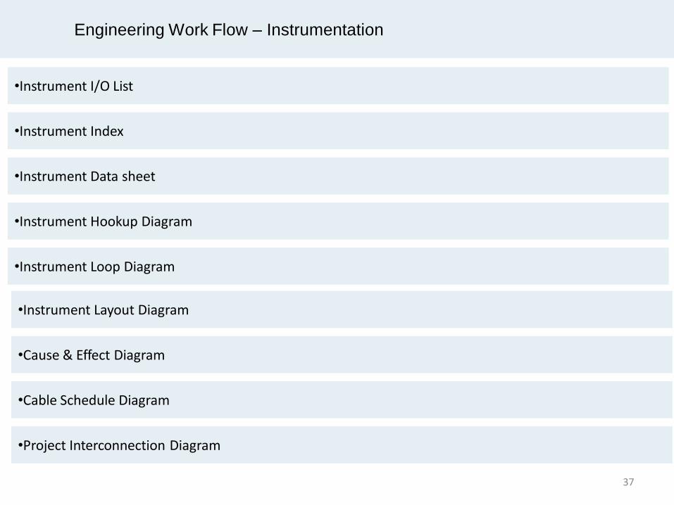
Engineering Work Flow – Instrumentation
•Instrument Index
•Instrument Data sheet
•Instrument Hookup Diagram
•Instrument Loop Diagram
•Instrument I/O List
•Instrument Layout Diagram
•Cause & Effect Diagram
•Cable Schedule Diagram
•Project Interconnection Diagram
37

Engineering Work Flow – Instrumentation
I/O List is a contains list of instrumentation which serve as an input or output of control system. Hence the tag number that physically has a cable which connects to the control system appears on I/O list.
Instrument index is a document containing list of instrument devices within a plant. Instrument index shall include tag number of all physical instruments
Reference Drawing P&ID, HMB
Instrument Index Reference Document
Cause & Effect
I/O Count will determines the required capacity of a system
38
Engineering Work Flow – Instrumentation
Instrument Data Sheet is a document containing specification and information of an instrument device. It specifies general information of instrument such as tag number identification, service description, location (line number/equipment number), P&ID number or drawing number reference, process data (if applicable), calibrated range (if applicable), material, performance details (such as accuracy, linearity – if applicable), hazardous certification (for electrical device), accessories required, etc. The details of information in data sheet may differ among each types of instrument such as transmitter, switch, gauge, control valve
Instrument Data Sheet
Reference Drawing P&ID, HMB,
Reference Document Instrument specification, piping specification, calculation, vendor catalogue
Once the data sheet completed, it is attached to requisition which to be sent to vendors. Vendors will offer their quotation with various model and manufacturer among the offers. Having been considered its technical and commercial aspects, the instrument is purchased. Following the purchase order, vendor will submit supporting document and drawing. Based on vendor data, instrument data sheet may be updated to accommodate details to make the data sheet “as-built”.
39
Engineering Work Flow – Instrumentation
Hook-up drawing is a detailed drawing showing mounting and connection of instrument to process lines and corresponding list of required material.
Hook-up drawing also gives information the requirement of bulk material for each installation. It also details its specification (size, type and material) and the quantity.
There are two types of hook-up drawing: 1. Process Hook-Up This hook-up drawing contains typical installations for instrument which connects to the process 1. Pneumatic Hook-Up
Hookup Drawing
Reference Drawing P&ID, Installation Detail
Specification, Piping Specification
40
Engineering Work Flow – Instrumentation
Instrument Layout is also known as instrument location plan. This drawing shows the exact position of each instruments with reference to plant layout.
The point indication of instrument position and its mounting stand where instrument to be mounted and process tap location.
Often the tap location and the instrument is separated quite distant. In some project, it is not mandatory to show the process tap location
Instrument Layout
Reference Drawing P&ID, Piping
Plan,piping GA and ISO
41

Engineering Work Flow – Instrumentation
Cable Schedule is a document containing list of instrument cables to install, cable type, length, origin, destination and route.
Reference Drawing Instrument Cable Layout,
Interconnection block diagram
Cable Schedule Reference Document
Instrument Index / I/O List
42

EPC Project Management
- Procurement Work Flow
43
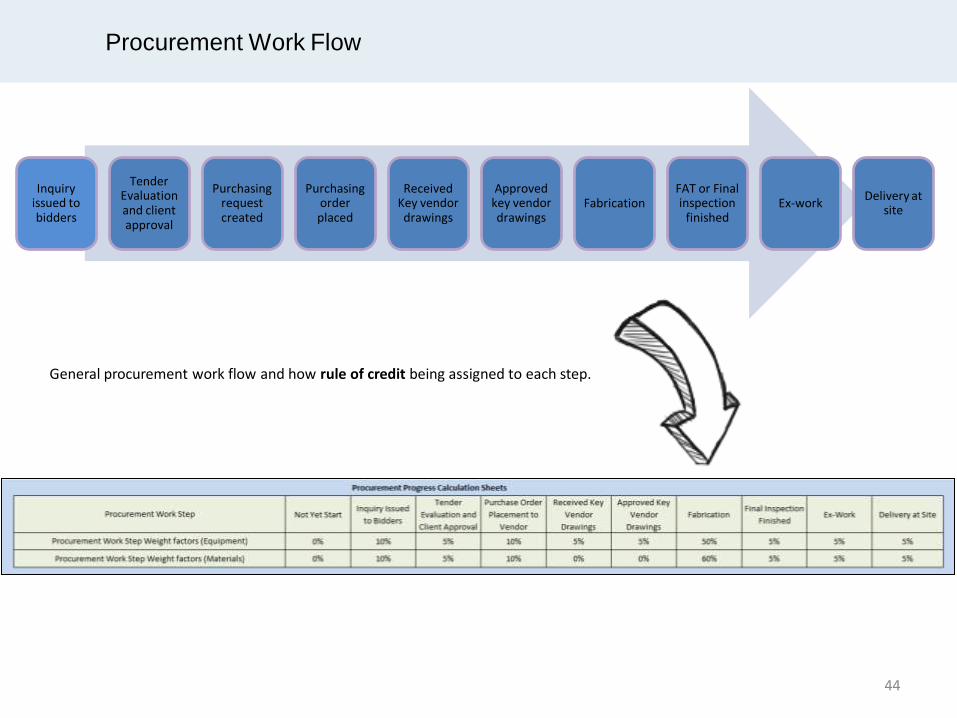
Procurement Work Flow
Inquiry issued to bidders
Tender Evaluation and client approval
Purchasing request created
Purchasing order placed
Received Key vendor drawings
Approved key vendor drawings
Fabrication FAT or Final inspection
finished Ex-work
Delivery at site
General procurement work flow and how rule of credit being assigned to each step.
44

Procurement Work Flow
Procurement progress calculation excel sheets are available for download in ignite.com
Progress tracking sheet for procurement work flow
45

Typical On-Shore Project Schedule and
Dependencies
46

Work front Concept
48

Work Front
Engineering progress is commonly measured by assigning a weight, usually the required number of required manhours, to each task/deliverable. Once the task is performed/ the deliverable is issued, the corresponding manhours are earned. The earned progress divided by the total number of manhours gives the % progress. As each engineering task/deliverable is scheduled at certain dates, it is possible to anticipate the progress that should be earned at a given date. It is the planned progress. At regular period, usually on a monthly basis, the actual progress of each activity/deliverable is measured against the planned progress. An actual progress less than the planned progress might show a lack of resources and a need for increased mobilization to get back on plan, following a (re-)forecast progress curve. Although such progress measure is commonly used, it could be deceiving. It indeed reflects rather well the progress of engineering on its own but not how well is engineering supporting the Project schedule. Let’s consider that engineering must issue 2 material requisitions, an urgent one for a Long Lead Item and another one which is required later on. Engineering will earn progress whatever requisition it issues, even if putting the Project in delay by issuing the non urgent requisition first. One sees that the above measure of progress alone is insufficient. It must be complemented by monitoring that important Milestones are met. These Milestones are first of all, the ones associated with the issue of the Requisition for the equipment. Long lead items have naturally to be purchased early. All equipment and packages also need to be purchased as early as their technical definition allows. Indeed, engineering development is highly dependent on information from vendors. The sooner the purchase orders are placed the sooner the vendor information will be available. Next come the Milestones associated with Bulk Material Procurement to support construction, such as the Piping MTO and the Structural Steel MTO (for an off-shore Project).
49

Work Front
Then come the Milestones associated with Construction. These are the IFC Plot Plan, a pre-requisite to start any site work, and the IFC P&IDs, a pre-requisite to the issue of Piping isometrics. The 50% IFC Piping isometric milestone comes next, which typically falls half way through the Project, as ensuing works, such as pre-fab and erection have a rather incompressible duration, due to site constraints (capacity of pre-fab shop, space constraints for erection limiting the progress). Even if engineering deliveries are in sequence, the above engineering progress measure might still be deceiving, as it will only reflect the amount of engineering work completed and not the workfront made available to construction. Let’s consider for instance that two foundations are to be cast. The first one is a very large foundation and the second one a small one. Issuing the drawing of either the large or small foundation will earn engineering the same progress, although it will open quite a different workfront to Construction. One sees the necessity to measure the issued Workfront. In the case of foundations, for instance, this will be done by monitoring the cumulative quantity of concrete (m3) of all issued IFC foundation drawings. Producing an S curve, such as the one shown in next slide, showing both planned and actually issued quantities will give a true picture of how well engineering is supporting civil works. One will similarly monitor, for an On-Shore project, the cumulative quantity of steel (tons) of issued IFC Structural drawings. The cumulative tons (or dia inch) of IFC issued Piping isometrics will show the available piping workfront. Such progress curves, showing the actual versus planned available workfronts are instrumental to monitor engineering progress, identify shortage and take corrective actions (increase mobilisation). It is not perfect however and can still be deceiving, in case of out-of-sequence issues: engineering may have issued drawings representing significant quantities, but that does not generate construction workfront as such works can not be performed at this time (due to lack of access or pre-requisite for another work to be completed before, for instance).
50
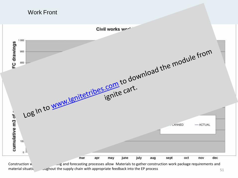
Work Front
Construction work-front planning and forecasting processes allow Materials to gather construction work package requirements and material situation throughout the supply chain with appropriate feedback into the EP process 51

Advanced Work Packaging
52

Work Face Planning
Path of Construction
EWP CWP FIWPs
500 – 1000mhrs
Construction drives Engineering & Procurement EWPs(Engineering Work Packages) are Engineering deliverables CWPs (Construction Work Packages)& FIWPs (Field Installation Work Packages) are Construction deliverables
System turn-over drives Construction
53

Work Face Planning
EWPs (Engineering Work Packages) set the precedence for Construction work.
Using the P&IDs (for item count) and Piping Layout Drawings (for lengths) a preliminary list for piping material requirement generated which known as piping MTO (piping material takeoffs) The GA drawing used for pipe erection while the piping ISO are used for pipe prefabrication. 54

Planned Path in Construction Work
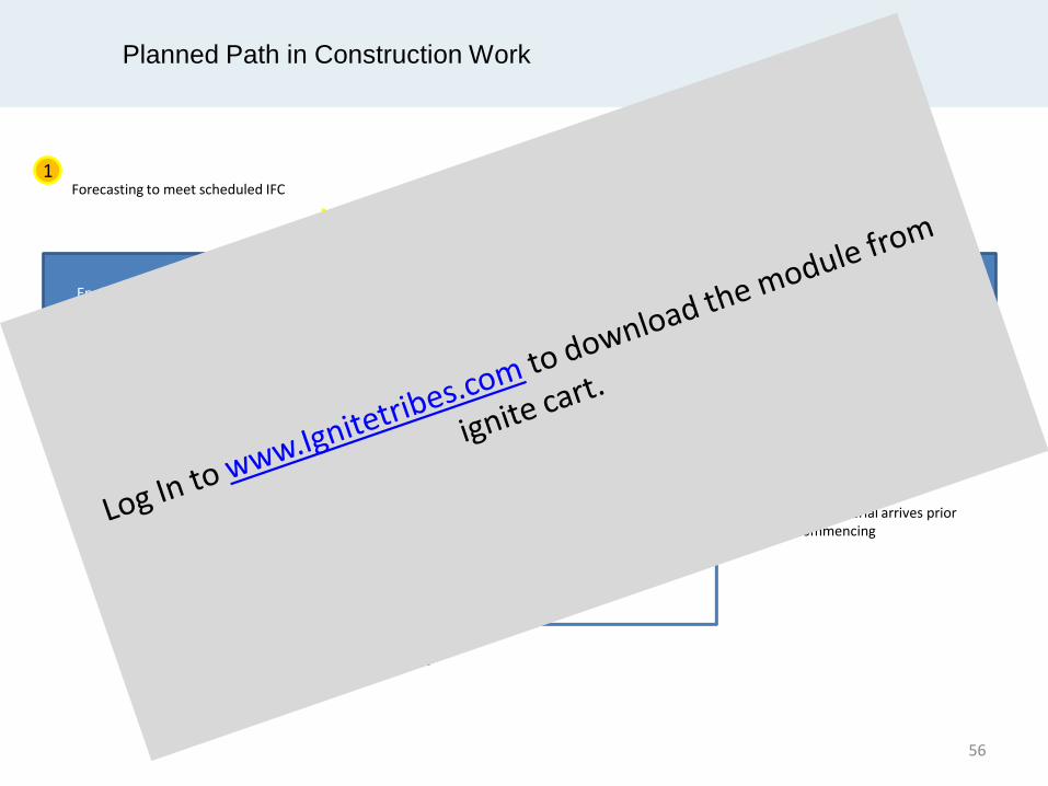
Engineering Work Package (EWP)
Procurement Package (PP)
Supplier Equipment / material
Construction Work Package (CWP)
9 weeks lag
Work commences
Equipment / Material arrives prior to work commencing Purchase Order to supplier
Engineering’s Bill of Material
55
Planned Path in Construction Work
Engineering Work Package (EWP)
Procurement Package (PP)
Supplier Equipment / material
Construction Work Package (CWP)
9 weeks lag
Work commences
Equipment / Material arrives prior to work commencing Purchase Order to supplier
Engineering’s Bill of Material
Forecasting to meet scheduled IFC Contractor resource mobilized
1 2
56
Constrained Path of Construction
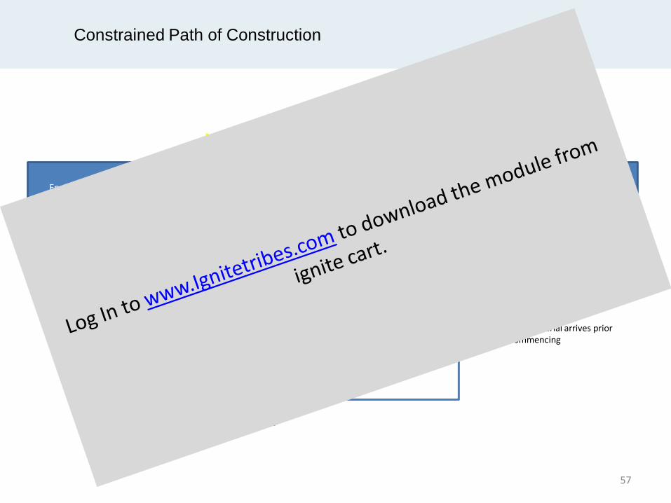
Engineering Work Package (EWP)
Procurement Package (PP)
Supplier Equipment / material
Construction Work Package (CWP)
9 weeks lag
Work commences
Equipment / Material arrives prior to work commencing Purchase Order to supplier
Contractor resource mobilized 2
Vendor Data needed to complete EW delivered late or incomplete
Lag gets squeezed CWP starts late
57

Constrained Path of Construction
Engineering Work Package (EWP)
Procurement Package (PP)
Supplier Equipment / material
Construction Work Package (CWP)
Work commences
Purchase Order to supplier
Contractor resource mobilized 2
How do we improve this interface?
58

Constrained Path of Construction
Engineering Work Package (EWP) Construction Work Package (CWP)
Work commences Delay in Engineering will cause lag gets squeezed CWP
starts late
Model Review causes late changes
MTO can’t be created
No IFC or AFC status for P&IDs
Specification is not complete
Client or EPC take longer time for document review and caused delay
How are these mitigated / eliminated?
It is important to knows the work sequence in order
to plan for Construction Work Package.
59

Engineering Work Package Progress
Ex : Piping Work Package.
2 P&IDs
3 Requisitions
4 Specifications.
1 3D modelling development
5 Pipe Stress analysis
6 Calculations
60

Forecasting Scenario
Ex : Piping Work Package.
Next Weekly Forecast - EWP slips one week
EWP is forecast to meet scheduled IFC
Next Weekly Forecast - EWP slips another week
Contractor plans resource mobilization
Contractor tries to mitigate
Delay in Construction work and recovery needed
Delay in Engineering Work Package approval in return cause
delay in construction work.
61

Potential Work Flow and Rule of Credit for Piping
Step Work Flow Increment % Cumulative %
1 EWP ID’d and mapped to CWP 5% 5%
2 Initial scope identified (line numbers) 15% 20%
3 Preliminary equipment data received 5% 25%
4 Initial routing of lines established 20% 45%
5 Initial bulk material (BOM) to supply chain 10% 55%
6 Piping studies rec’d for critical lines: 5% 60%
7 Final vendor data received 10% 70%
8 Final routings completed 5% 75%
9 P&IDs and LDT issued IFC 5% 80%
10 Stress analysis for large bore completed 5% 85%
11 BOM completed 5% 90%
12 EWP c/w all drawings/specs issued IFC 5% 95%
13 EWP accepted by Construction AFC 5% 100%
62
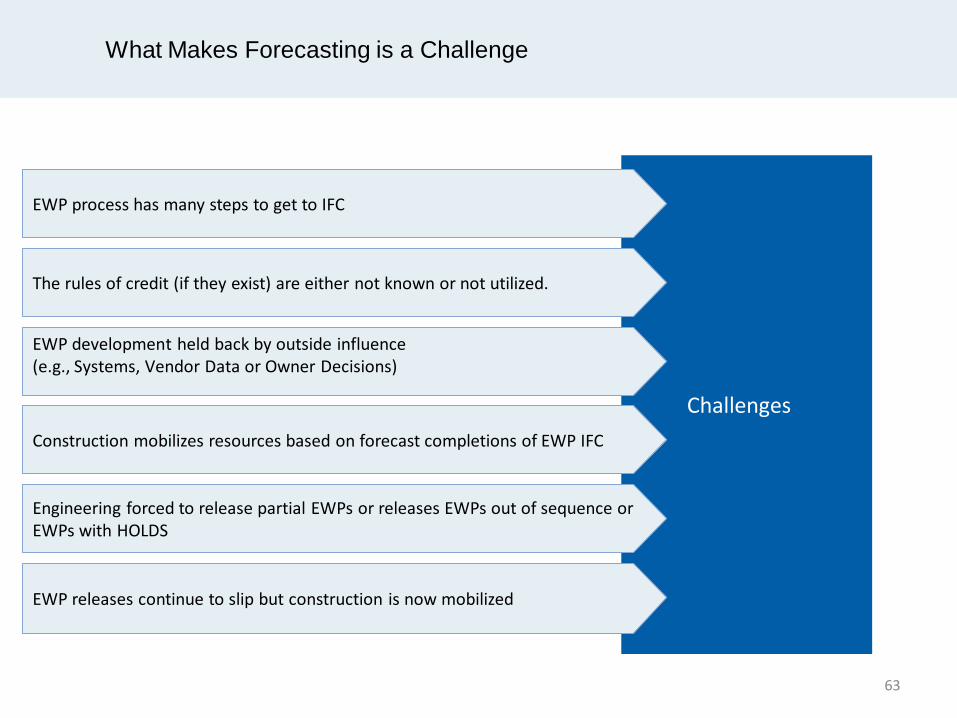
What Makes Forecasting is a Challenge
Challenges
EWP process has many steps to get to IFC
The rules of credit (if they exist) are either not known or not utilized.
EWP development held back by outside influence (e.g., Systems, Vendor Data or Owner Decisions)
Construction mobilizes resources based on forecast completions of EWP IFC
Engineering forced to release partial EWPs or releases EWPs out of sequence or EWPs with HOLDS
EWP releases continue to slip but construction is now mobilized
63
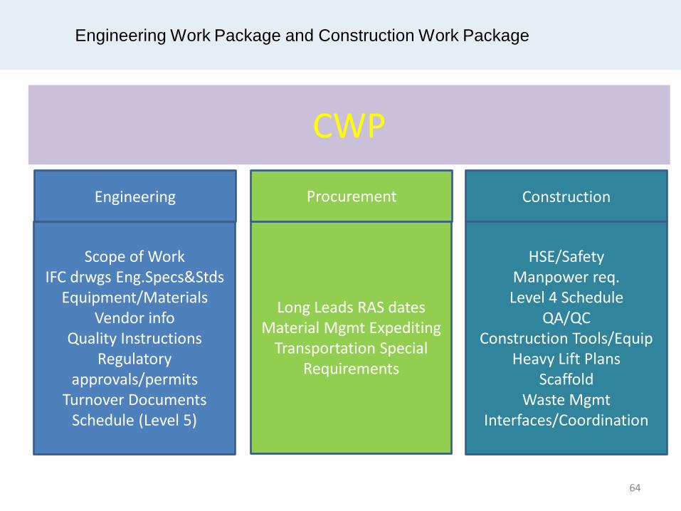
Engineering Work Package and Construction Work Package
CWP
Scope of Work
IFC drwgs Eng.Specs&Stds Equipment/Materials
Vendor info Quality Instructions
Regulatory approvals/permits
Turnover Documents Schedule (Level 5)
Engineering
Long Leads RAS dates
Material Mgmt Expediting Transportation Special
Requirements
Procurement
HSE/Safety Manpower req. Level 4 Schedule
QA/QC Construction Tools/Equip
Heavy Lift Plans Scaffold
Waste Mgmt Interfaces/Coordination
Construction
64
Sample WBS
65


WBS Structure
67

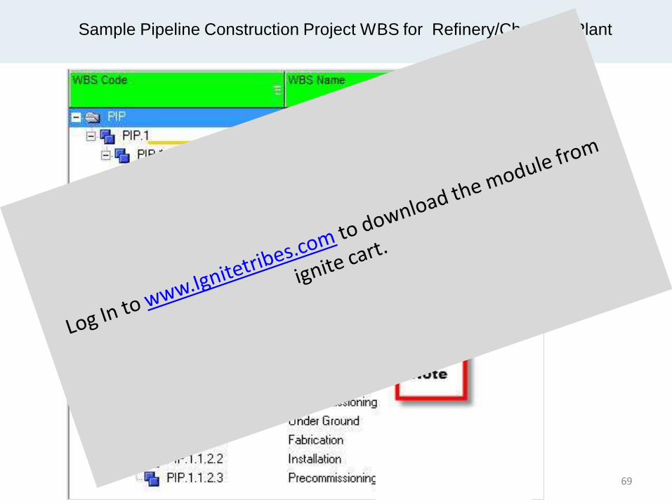
Sample Pipeline Construction Project WBS for Refinery/Chemical Plant
69

Sample Pipeline Construction Project WBS for Refinery/Chemical Plant
Sample WBS for piping construction project for a refinery or chemical plant may be organized as the following. It is worth to be organized by location wise (i.e. platform and pipe rack, platform and equipment around piping) prior to “Phase” WBS. Timely completion of piping construction is not only depending on timely receiving of engineering drawings and materials from Owner/EPC contractor but timely availability of the infrastructure should also be addressed. Sometime it refers to work front availability. Developing WBS is mainly depending on the project scope. It should be defined according to the project specific as every project is different, for instance, “Demolishing” WBS may also be added under “Phase” level priority to “Installation” WBS if your project scope involved a considerable amount of piping demolishing scope. “Above Ground” and “Under Ground” WBS can be left in case no underground piping work is included in the project. (1) Level 1: Plant Unit, e.g. Utility Unit, Ethylene Theatre Unit, etc. (2) Level 2: Area within a Unit, for instance, Area ABC, Area XYZ. Area demarcation is marked for a group of process piping on above ground and underground. (3) Level 3: Height. This is to segregate pipe work on the above ground and underground. (4) Level 4: Location where pipeline is run, for instance, piping on and around pipe rack, equipment and equipment platform. (5) Level 5: Phase, e.g. Fabrication, Installation (field erection, NDT) and pre-commissioning (hydro testing, air flushing, chemical cleaning etc.) Note : “Common” WBS name refers to common location where interconnecting piping is running between the pipe rack and equipment or equipment platform. Having a clear definition of what is and what is not meant by “Common” is important
70
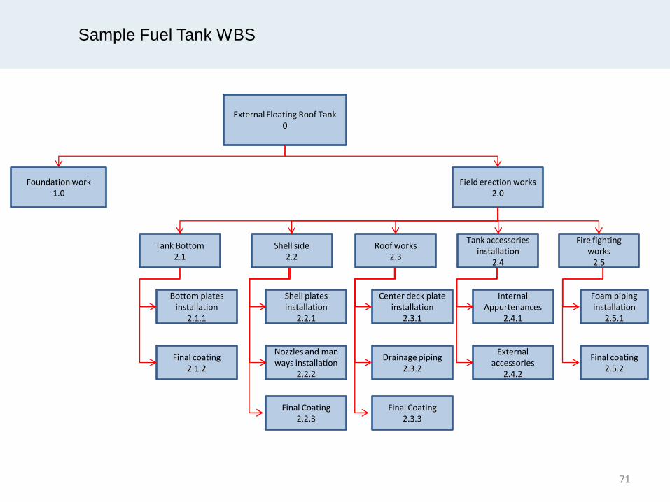
Sample Fuel Tank WBS
External Floating Roof Tank 0
Foundation work 1.0
Field erection works 2.0
Tank Bottom 2.1
Shell side 2.2
Roof works 2.3
Tank accessories installation
2.4
Fire fighting works
2.5
Bottom plates installation
2.1.1
Final coating 2.1.2
Shell plates installation
2.2.1
Nozzles and man ways installation
2.2.2
Final Coating 2.2.3
Center deck plate installation
2.3.1
Drainage piping 2.3.2
Final Coating 2.3.3
Internal Appurtenances
2.4.1
External accessories
2.4.2
Foam piping installation
2.5.1
Final coating 2.5.2
71

Piping Discipline
( Piping Fabrication, Tie-in and Commissioning )
73
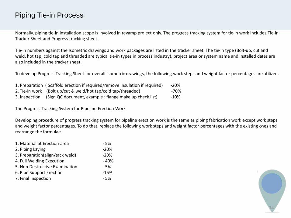
Piping Tie-in Process
Normally, piping tie-in installation scope is involved in revamp project only. The progress tracking system for tie-in work includes Tie-in Tracker Sheet and Progress tracking sheet. Tie-in numbers against the Isometric drawings and work packages are listed in the tracker sheet. The tie-in type (Bolt-up, cut and weld, hot tap, cold tap and threaded are typical tie-in types in process industry), project area or system name and installed dates are also included in the tracker sheet. To develop Progress Tracking Sheet for overall Isometric drawings, the following work steps and weight factor percentages are utilized. 1. Preparation ( Scaffold erection if required/remove insulation if required) -20% 2. Tie-in work (Bolt up/cut & weld/hot tap/cold tap/threaded) -70% 3. Inspection (Sign QC document, example : flange make up check list) -10% The Progress Tracking System for Pipeline Erection Work Developing procedure of progress tracking system for pipeline erection work is the same as piping fabrication work except work steps and weight factor percentages. To do that, replace the following work steps and weight factor percentages with the existing ones and rearrange the formulae. 1. Material at Erection area - 5% 2. Piping Laying -20% 3. Preparation(align/tack weld) -20% 4. Full Welding Execution - 40% 5. Non Destructive Examination - 5% 6. Pipe Support Erection -15% 7. Final Inspection - 5%
74
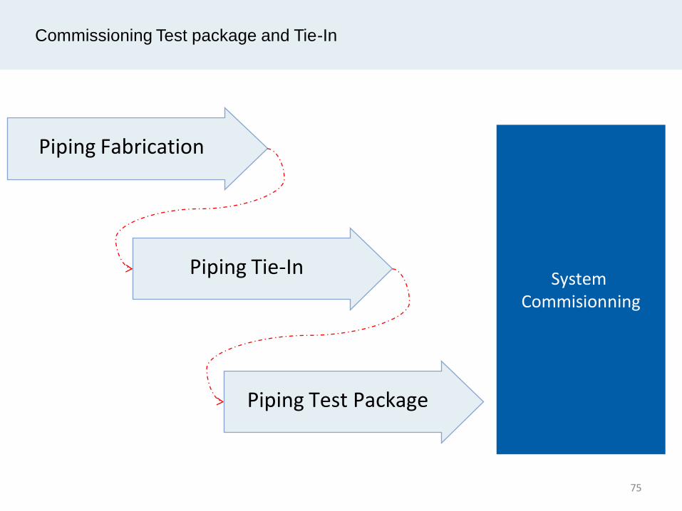
Commissioning Test package and Tie-In
System Commisionning
Piping Fabrication
Piping Tie-In
Piping Test Package
75

Piping Tie-in Work Sequence
General piping tie-in work flow and how rule of credit being assigned to each step.
Weld map drawing
preparation
Withdrew material
Welding preparation
Spool assemble and
tack weld Welding NDT
Surface preparation and coating
Final inspection
Delivery at site
76

Piping Hydrotest Work Sequence
Preparation Done Testing Reinstated Clear Punch list
General hydrotest work flow and how rule of credit being assigned to each step.
77
Commissioning Test package and Tie-In
Test Package for Pre- Commissioning Tie-In List
78


Vessel Fabrication
83
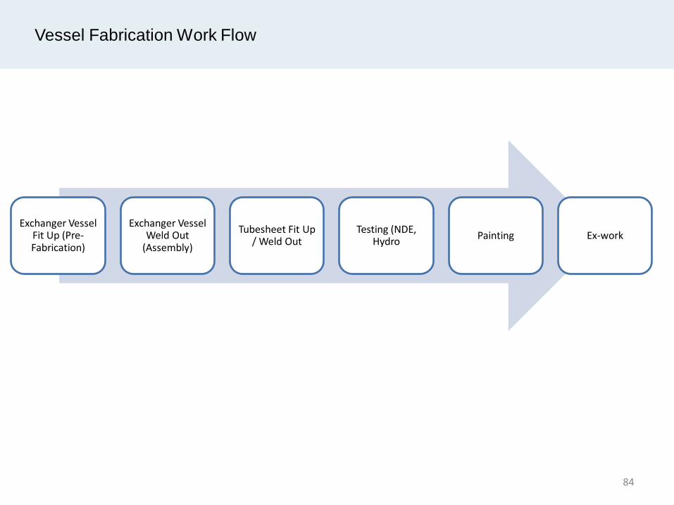
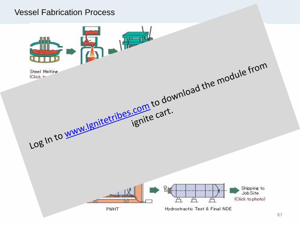
Vessel Fabrication Work Flow
Exchanger Vessel Fit Up (Pre-Fabrication)
Exchanger Vessel Weld Out
(Assembly)
Tubesheet Fit Up / Weld Out
Testing (NDE, Hydro
Painting Ex-work
84

Vessel Fabrication Work Flow
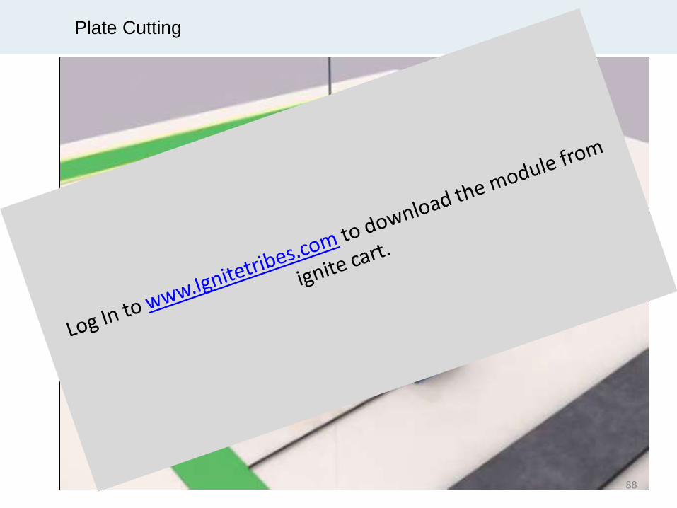
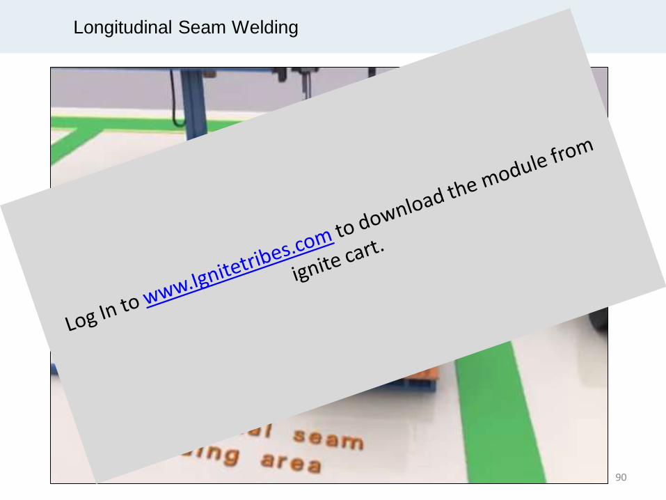
Shell Side Fabrication · Plate marking /cutting/ beveling and inspection · Shell plate rolling work · Longitudinal steel (LS) fit-up and inspection · LS welding and inspection (NDE) · Circumference steel (CS) fit-up and inspection · CS welding and inspection (NDE) Inlet and outlet nozzles fabrication · Pipe marking/cutting / beveling and inspection · Fit-up and welding of flanges and pipes · Inspection for nozzles to flange joints (NDE) Nozzle Attachments to Dished Head · Marking of nozzle location on dished head · Cutting/opening/ beveling and inspection · Fit-up and tack weld nozzle to dished head · Inspection for tack welding (if required) · Full weld - nozzle assembly with dished head · Inspection for nozzle to dished head welds (NDE) Nozzles and other accessories to Shell · Marking of nozzles location · Cutting/opening/ beveling and Inspection · Fit-up and tack weld nozzle assembly to shell/inspection · Full weld - nozzle assembly with shell · Inspection for nozzle to shell side welds (NDE) · Fit up and welding for instrument attachments · Fit up and welding for lifting lugs
Dished head Installation · Fit up and tack weld/Inspection – Dished head to shell · Full circumference welding · Inspection for full welds (NDE) Inspection (Hydro-testing) · Hydrostatic testing · Draining/drying and final inspection Blasting and Painting · Blasting/Inspection · Primer/Final coating/Inspection
85
Vessel Fabrication Case Study
86


Weld Outside Circumference of Can
98
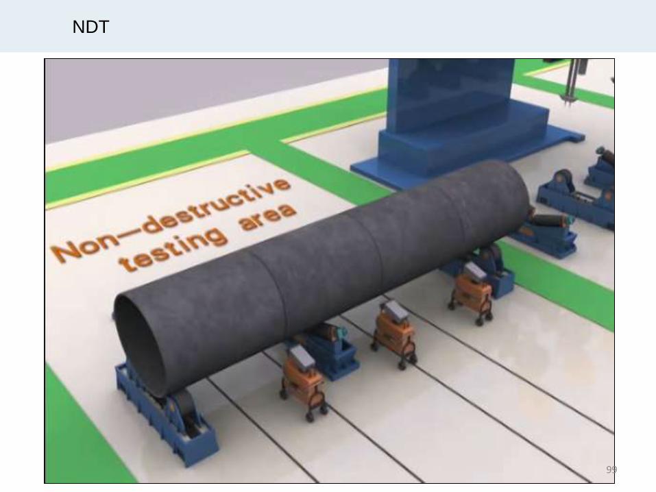
NDT
99


The End
101