epc 25 - · pdf fileinput voltage 230 to 400 vac output voltage 10 to 200 (370) vdc ... epc...
TRANSCRIPT
EPC 25
Power supply and control unit for electro-permanent lifting devices
Instruction manual
Power supply and control unit for electro-permanent lifting devices
4 ATHEA Microsystems
Copyright © 2002-2007 ATHEA Microsystems®
Contents of this document are spiritual property of ATHEA Microsystems Company. Without a former written consent of ATHEA Microsystems Company no part can be copied or multiplied in any possible way (printing, photocopy, microfilm or any other way), placed in the information system or transmitted in another form or by any other means. ATHEA Microsystems Company cannot assume any legal responsibility nor provide any guarantee against using of false information with its following consequences. Claims to compensation based on modifications, mistakes or omissions are impossible in principle. ATHEA Microsystems Company reserves its right to modify and improve the product described in this user manual anytime without previous notice. All registered or other trademarks used in this user manual are the property of their owners. By mentioning them no property rights ensuing from them are challenged. ATHEA Microsystems is the registered trademark – Office of Industrial Property, trademark No.249691.
EPC 25
www.athea.cz 5
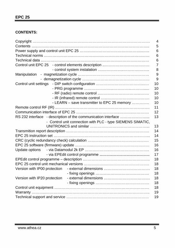
CONTENTS: Copyright …………………………………………………………………………………. 4 Contents …..…….……………………………………………………………………….. 5 Power supply and control unit EPC 25 ……..…..………………………………...….. 6 Technical norms ….………………..………………….………………………………… 6 Technical data ..…………………………………………………….…………………… 6 Control unit EPC 25 - control elements description ..……………………………… 7 - control system instalation ….……………..………….…….. 8 Manipulation - magnetization cycle ………………………………………………… 9 - demagnetization cycle ……………………………………………… 9 Control unit settings - DIP switch configuration ………………………………....… 10 - PRG programme …………………...…………...………...... 10 - RF (radio) remote control ..…………………………...……. 10 - IR (infrared) remote control …...………………...…………. 10 - LEARN – save transmitter to EPC 25 memory ………….. 10 Remote control RF (IR) ..……………………………….………………………………. 11 Communication interface of EPC 25 ……………………………..………..…………. 12 RS 232 interface - description of the communication interface …………………... 13
- Control unit connection with PLC - type SIEMENS SIMATIC, UNITRONICS and similar ………………………………………... 13
Transmition report description ………………………………..……………………….. 14 EPC 25 instruction set …………….……………………………………………..……... 14 CRC (cyclic redundancy check) calculation …………………………………………. 15 EPC 25 software (firmware) update …………...……………………………………… 16 Update options - via Datamodul 2k EP ………………..………………………….. 16 - via EPEdit control programme ……………………………………… 17 EPEdit control programme – description .…………………………………………….. 18 EPC 25 control unit mechanical versions ……….…….….………………………….. 18 Version with IP00 protection - external dimensions ………………………………. 18 - fixing openings ……………………………………. 18 Version with IP20 protection - external dimensions ………………………………. 18 - fixing openings ……………………………………. 18 Control unit equipment …………………………………………………………………. 18 Warranty ………...……………………………………………………………………….. 19 Technical support and service ………………………………………………………… 19
Power supply and control unit for electro-permanent lifting devices
6 ATHEA Microsystems
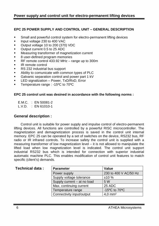
EPC 25 POWER SUPPLY AND CONTROL UNIT – GENERAL DESC RIPTION Small and powerful control system for electro-permanent lifting devices Input voltage 230 to 400 VAC Output voltage 10 to 200 (370) VDC Output current 0.5 to 25 ADC Measuring transformer of magnetization current 8 user-defined program memories RF remote control 433.92 MHz – range up to 300m IR remote control RS 232 industrial bus support Ability to comunicate with common types of PLC Galvanic separation control and power part 1 kV LED signalization – Power, TxD/RxD, Error Temperature range : -15ºC to 70ºC
EPC 25 control unit was desined in accordance with the following norms : E.M.C. : EN 50081-2 L.V.D. : EN 61010-1
General description : Control unit is suitable for power supply and impulse control of electro-permanent lifting devices. All functions are controlled by a powerful RISC microcontroller. The magnetization and demagnetization process is saved in the control unit internal memory. EPC 25 can be operated by a set of switches on the device, RS232 bus, RF radio or IR infrared controls. To increase safety the control unit is supplied with a measuring transformer of low magnetization level – it is not allowed to manipulate the lifted load when low magnetization level is indicated. The control unit support industrial RS232 bus which is intended for connection with superior industrial automatic machine PLC. This enables modification of control unit features to match specific (client’s) demands.
Parameter Value Power supply 230 to 400 V AC/50 Hz Supply voltage tolerance ±10 % Supply current – at no load 5 W Max. continuing current 25 ADC Temperature range -15ºC to 70ºC
Technical data :
Connectivity input/output 4,0 mm²
EPC 25
www.athea.cz 7
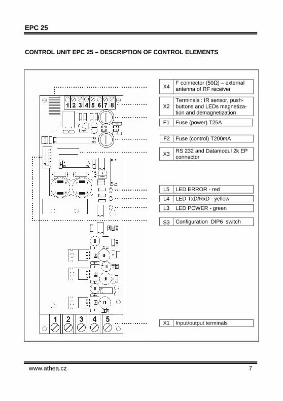
CONTROL UNIT EPC 25 – DESCRIPTION OF CONTROL ELEMEN TS
X4 F connector (50Ω) – external antenna of RF receiver
X2
Terminals : IR sensor, push-buttons and LEDs magnetiza-tion and demagnetization
F1 Fuse (power) T25A
F2 Fuse (control) T200mA
X3 RS 232 and Datamodul 2k EP connector
L5 LED ERROR - red
L4 LED TxD/RxD - yellow
L3 LED POWER - green
S3 Configuration DIP6 switch
X1 Input/output terminals

Power supply and control unit for electro-permanent lifting devices
8 ATHEA Microsystems
INSTALLATION : Control units are supplied in IP00 protection version for inbuilding into the magnet
or in IP20 increased protection. When installing it is necessary to connect protective terminal. Power supply is to be connected to terminals 1 and 2. Connect magnet to terminals 4 and 5. Magnetization and demagnetization pushbuttons and light are to be attached to
connector X2.
EPC 25
www.athea.cz 9
MANIPULATION : Before lifting load it is necessary to carry out following operations : Clean the surface of the load to ensure sufficient contact area. Place magnet onto gravity centre of load. MAGNETIZATION – LOAD CLAMPING : Press green pushbutton S1 for 0.5 sec as a minimum. During the magnetization cycle the green LED L1 is flashing. After the magnetization cycle the green LED L1 is either constantly on or it is
flashing in the intervals of 0.5 sec.
Green indicator L1 is on – the load has been successully clamped. Magnetization curent reached safe level. This level is set by manufacturer and is saved in control unit memory.
Green indicator L1 is flashing (magnetization error ) – red light L5 on front panel is on. Magnetization current has not reached safe level – IT IS FORBIDDEN TO MANIPULATE WITH CLAMPED LOAD. This can occure due to following causes : Low input voltage Disconnected coil of magnet Faulty fuse F1 Damaged power part of control unit
DEMAGNETIZATION : Press red pushbutton S2 for 0.5 sec as a minimum. During the demagnetization cycle the red LED L2 is flashing. Once demagnetizied the red LED L2 is permanently on.
Note : demagnetization current is not measured during the process.
Power supply and control unit for electro-permanent lifting devices
10 ATHEA Microsystems
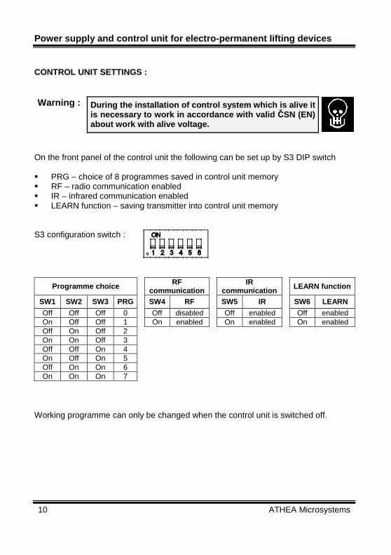
CONTROL UNIT SETTINGS : Warning : During the installation of control system which is alive it
is necessary to work in accordance with valid ČSN (EN) about work with alive voltage.
On the front panel of the control unit the following can be set up by S3 DIP switch PRG – choice of 8 programmes saved in control unit memory RF – radio communication enabled IR – infrared communication enabled LEARN function – saving transmitter into control unit memory S3 configuration switch :
Programme choice RF communication
IR
communication LEARN function
SW1 SW2 SW3 PRG SW4 RF SW5 IR SW6 LEARN
Off Off Off 0 Off disabled Off enabled Off enabled On Off Off 1 On enabled On enabled On enabled Off On Off 2 On On Off 3 Off Off On 4 On Off On 5 Off On On 6 On On On 7
Working programme can only be changed when the control unit is switched off.
EPC 25
www.athea.cz 11
REMOTE CONTROL RF (IR) General description : Due to the high safety of operation requirement a unique KEELOQ coding system by Microchip Technology Inc. is used for codin and decoding of transmitted commands. This systém ensures high reliability of data transmittion by using the technology of hoping code HCS. EPC 25 control unit communicate solely with remote controls by ATHEA Microsystems – remote controls by other manufactures are ignored by the control unit. “LEARN“ FUNCTION – SAVING TRANSMITTER INTO THE CONT ROL UNIT MEMORY EPC 25 control unit can be operated by RF radio or IR infrared remote controls. Up to 6 different remote controls (RF or IR) can be saved into the control unit memory. RF or IR remote control can be saved into the memory as follows : Switch S3 (SW6) to LEARN – On position Once LED L4 TxD/RxD is alight immediately return S3 (SW6) switch to LEARN –
Off position Press random pushbutton on the remote control several times. If LED L4 TxD/RxD flashed several times and subsequently then goes off the
remote control has been saved into the control unit memory. DELETING TRANSMITTERS FROM CONTROL UNIT MEMORY : All transmitters saved in the control unit memory can be deleted as followings : Switch S3 (SW6) to LEARN – On position Wait 8 sec. Once LED L4 TxD/RxD light goes off the memoryhas been deleted. Switch S3 (SW6) to LEARN – Off position.

Power supply and control unit for electro-permanent lifting devices
12 ATHEA Microsystems
RS 232 COMMUNICATION INTERFACE : RS 232 interface has been designed to connect the control unit with industrial automatic machine PLC or with PC. Control unit communicate with maximum speed of 33.6 kBd (1.2 kBd being the standard speed). All signals are driven out to the X3 connector and are galvanic separated from the power part. Condition needed for reliable data transmission : • Power and data circuits separation. • Use of shielded communication cable. • In ideal conditions the distance between the comunicating device should not
exceed 30 m.
Communication speed 1,2 kBd
Number of data bits 8
Parity None
Stop-bits 1
Outcoming/incoming data form :
Data flow control None
Pin number Signal description
1 SDA – I2C bus DATA signal
2 SCL –I2C bus CLOCK signal
3 TEST – control signal
4 RxD – incoming data RS232
5 TxD – outcoming data RS232
6 GND – power supply
X3 connector description :
7 + 5V – power supply
Note : TxD and RxD data signals are TTL compatible. For connection to RS 232 bus it is neccessary to use Datamudule 2k EP which converts and inverts TTL signals to RS 232 signals.

EPC 25
www.athea.cz 13
INTERCONNECTION OF THE CONTROL UNIT WITH PLC SIEMENS SIMATIC PLC industrial automatic machine which is equipped with Freeport (free programmable UART serial link with supported ASCII record) can be interconnect with control unit by 9-cored shielded conductor. RS 232 transmission report description Control unit continously monitors series data on the RxD input. The incoming data on this input must be in ASCII format in hexadecimal form. Once the data in correct format and with the correct target device address is received the requested order is carried out. Once the requested operation is completed the control unit send a message to the superior PLC.
Power supply and control unit for electro-permanent lifting devices
14 ATHEA Microsystems
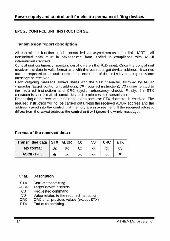
EPC 25 CONTROL UNIT INSTRUCTION SET Transmission report description : All control unit function can be controlled via asynchronous serial link UART. All transmitted data must in hexadecimal form, coded in compliance with ASCII international standard. Control unit continously monitors seriál data on the RxD input. Once the control unit receives the data in valid format and with the correct target device address, it carries out the requsted order and confirms the execution of the order by sending the same message as received. Each outgoing message always starts with the STX character, followed by ADDR character (target control unit address), C0 (required instruction), V0 (value related to the required instruction) and CRC (cyclic redundancy check). Finally, the ETX character is sent out which concludes and terminates the transmission. Processing of the received instruction starts once the ETX character is received. The required instruction will not be carried out unless the received ADDR address and the address saved into the control unit memory are in agreement. If the received address differs from the saved address the control unit will ignore the whole message. Format of the received data :
Transmitted data STX ADDR C0 V0 CRC ETX
Hex format 02 0x 0x xx xx 03
ASCII char. xx xx xx xx ♥
Char. Description
STX Start of transmitting ADDR Target device address
C0 Requested command V0 Value related to the required instruction
CRC CRC of all previous values (except STX) ETX End of transmitting

EPC 25
www.athea.cz 15
EPC 25 CONTROL UNIT INSTRUCTIONS DESCRIPTION
C0 instruction code (Hex) C0 instruction description Range of permitted
values V0 01 START magnetization xx
02 START demagnetization xx Note : xx - random value
Calculation of CRC – using XOR metod
Examples of ASCII strings :
STOP Magnetization (address 00) : 00000000 ♥
START Demagnetization (address 00) : 00020002 ♥

Power supply and control unit for electro-permanent lifting devices
16 ATHEA Microsystems
CONTROL UNIT SOFTWARE (FIRMWARE) UPDATE Software update via Datamodule 2k EP :
Datamodul – memory which stores all information needed for working of the control unit. Datamodule is also neccessary for connection of the control unit with PC via RS 232.
Information saved in Datamodule can be moved to the control unit as followings : Turn off the control unit Insert Datamodule to X3 connector Turn on the control unit During the data transmittion from Datamudule to control unit the yellow LED – TxD / RxD is on. The control unit programmed in this way will save its data even after the disconnection of feeding voltage in its internal EEPROM memory – after the finishing of the programme cycle it is suitable to take the Datamodule out of the connector.
EPC 25
www.athea.cz 17
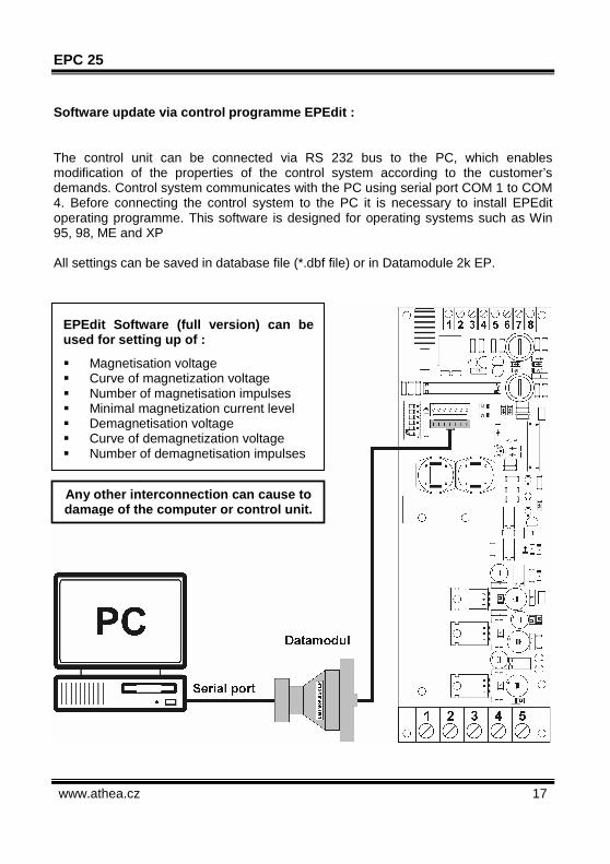
Software update via control programme EPEdit : The control unit can be connected via RS 232 bus to the PC, which enables modification of the properties of the control system according to the customer’s demands. Control system communicates with the PC using serial port COM 1 to COM 4. Before connecting the control system to the PC it is necessary to install EPEdit operating programme. This software is designed for operating systems such as Win 95, 98, ME and XP All settings can be saved in database file (*.dbf file) or in Datamodule 2k EP.
EPEdit Software (full version) can be used for setting up of :
Magnetisation voltage Curve of magnetization voltage Number of magnetisation impulses Minimal magnetization current level Demagnetisation voltage Curve of demagnetization voltage Number of demagnetisation impulses
Any other interconnection can cause to damage of the computer or control unit.

Power supply and control unit for electro-permanent lifting devices
18 ATHEA Microsystems
CONTROL PROGRAMME EPEDIT – DESCRIPTION : Before installing of EPEdit it is neccessary to check all components according to the following list. In case of any discrepancy with the list, or if any item is damaged (e.g. illegible installation CD-ROM), please contact your supplier. List of equipment of control unit EPC 25 : • User manual in Czech and English version. • Communication cable for connection of control unit EPC 25 to PC. • Datamodul 2k EP
CONTROL PROGRAMME EPEdit :
EPC 25
www.athea.cz 19
WARANTY Guarantee conditions
There is a 12-month-guarantee for the given product since the day of purchase. During this period the supplier agrees to repair or exchange free of charge all parts with defects obstructing their proper use according to the producer instructions. This concerns parts which have latent defects or which do not correspond by their configuration with the product documentation and technical conditions of the product. The transport costs are to be covered by the customer.
The guarantee does not apply to : • defects caused by improper use of product, e.g. incorrect connection to the
network or to the signal sources, incorrect connection of circuits, overloading or interference with the product.
• defects caused by external influences, e.g. damage caused by transport, crash, heat, water, aggressive substances, etc.
• signal lights, control elements, circuit breaker and power semiconductor elements (thyristors, triacks, diodes, etc.)
• eventual idle time of the machine as a result of the defect of the product.
We hope that you will be fully satisfied
with our products.
Date :
S.N. :
Stamp of supplier:
Sign. :
Guarantee and post-guarantee service is provided by:
Martin Valeš Sídliště 322 672 01 Moravský Krumlov Czech Republic Tel.: +420 605 892 095 E-mail : [email protected] Internet : www.athea.cz