ep1305n 5 gallon can extruder system rev. a august 2013 · ep1305n 5 gallon can extruder system...
TRANSCRIPT

EP1305N 5 Gallon Can Extruder System Rev. A August 2013
1
EP1305N Operation Manual
EP1305N 5 Gallon Can Extruder System Rev. A August 2013
2
THIS PAGE HAS BEEN INTENTIONALLY LEFT BLANK

EP1305N 5 Gallon Can Extruder System Rev. A August 2013
3
TABLE OF CONTENTS
SECTION 1: SAFETY ............................................................................................................................................... 4
1. GENERAL SAFETY ..................................................................................................................................... 5
2. PUMP SAFETY ......................................................................................................................................... 5
3. FLUID PRESSURE AND COMPATIBILITY ....................................................................................................... 6
4. DANGER ................................................................................................................................................. 6
5. HOSE SAFETY .......................................................................................................................................... 6
6. EXPLOSIVE DANGER ................................................................................................................................. 7
SECTION 2: INSTALLATION ..................................................................................................................................... 8
1. SELECTING THE CORRECT INSTALLATION LOCATION ..................................................................................... 9
2. CONNECTION AND SEPARATION OF AIR HOSE .............................................................................................. 9
2.1. CONNECTION ...................................................................................................................................... 9
2.2. SEPARATION ....................................................................................................................................... 9
SECTION 3: OPERATING PROCEDURES .................................................................................................................. 10
1. DEPRESSURIZING THE AIR PRESSURE ....................................................................................................... 11
2. START AND CONTROL OF UNIT ................................................................................................................ 11
2.1 MAIN INSTALLATION ............................................................................................................................ 11
2.2 FLUID OPERATION ............................................................................................................................... 12
2.3 CHANGING THE CONTAINER .................................................................................................................. 12
3. PROCEDURE OF DEPRESSURIZING THE AIR PRESSURE ................................................................................ 13
4. DISASSEMBLY & ASSEMBLY .................................................................................................................... 13
4.1 DISASSEMBLY ........................................................................................................................................ 13
4.2 ASSEMBLY ............................................................................................................................................ 14
5. STORAGE .............................................................................................................................................. 15
SECTION 4: FIGURES, TABLES AND GRAPHS ........................................................................................................... 16
SECTION 5: TECHNICAL DATA .............................................................................................................................. 25
6. TECHNICAL DATA................................................................................................................................... 26
SECTION 6: TROUBLESHOOTING GUIDE................................................................................................................. 27
7. TROUBLESHOOTING GUIDE ..................................................................................................................... 28

EP1305N 5 Gallon Can Extruder System Rev. A August 2013
4
Section 1: SAFETY
EP1305N 5 Gallon Can Extruder System Rev. A August 2013
5
Improper use of the high-pressure pump may cause serious injury. Please read and understand the entire Operational Manual before using the pump.
1. GENERAL SAFETY
In using the dispensing equipment, the excessive fluid pressure, change of parts, inadequate chemical fluid use may cause the parts to become damaged. Eyes & skin may be exposed to the fluid. Serious injury, fire or explosion may occur. Do not change any parts of equipment without proper guidance. Malfunction may occur. The equipment needs to be checked at regular intervals and repaired as necessary. Worn and damaged parts should be exchanged immediately. Wear protective equipment such as glasses, gloves, clothing, and mask as recommended by the material manufacturer.
2. PUMP SAFETY
See Figure 1 and Table 1 for below; Two countermeasures for the safety of the pump are deflating the air (Table 1, item 25-4) in the valve for operating the pump and in the fluid area. If you want to use the pump and the pump is to be repaired, these countermeasures will protect the operator from exposure to parts during movement, and exposure of eyes and skin to the fluid. The ball valve for operating the pump (Table 1, item 8) can shut off the air between the pump and the valve after operating the air. This valve can shut off the air provided into the pump in accordance with the control of the pump regulator. The ball valve (Table 1, item 25-4) for deflating the air in the fluid can lessen the fluid pressure in the pump, hose and in the dispensing valve. - When the ball valve (Table 1, item 8) is closed, the valve for operating the pump shuts off the air between the air motor and the valve. - The pump regulator (Table 1, item 27A) controls the pressure provided into the pump and the operating speed of pump. - The ram regulator (Table 1, item 27B) controls the up/down operating speed of the ram and the pressure provided into the ram. It also controls the pressure in the pad plate on the fluid container. - The valve for deflating the air in the fluid area (Table 1, item 25-4) can lessen the fluid pressure in the pump and hose and in the dispensing valve.

EP1305N 5 Gallon Can Extruder System Rev. A August 2013
6
3. FLUID PRESSURE AND COMPATIBILITY
The fluid pressure should be maximum 60 bar (850 psi) or the air pressure should be less than maximum 7 bar (100 psi). All dispensing equipment and accessories are suitable for the maximum pressure of the pump. However, please follow the scope of maximum pressure of all parts and accessories. All fluids and solvents are compatible with the liquid materials chemically as shown in the technical data. Please carefully read the technical data by the material manufacturer before using fluid and solvent in the pump.
4. DANGER
In order to lessen the danger of accidents, keep hands and fingers away from the priming piston while the air is installed into the pump. Always follow the procedure of depressurizing the air pressure before the removal of any parts or checking and cleaning them. While the priming piston and the pump is in operation, the cutting of hands or fingers, the damage of tools and the damage between the piston and intake valve may occur. The air motor, the fluid area of pump and the motor are operated when the air is provided into the motor area. Keep hands and fingers away from the air motor during the test at the time of installing the pump. Be sure to follow the procedure of depressurizing the air pressure above in order to prevent the unexpected operation before operating the pump. The pad plate or the hose and pump bracket are operated in accordance with the up/down operation of ram. In this case, keep hands away from the edge of the ram or the pump bracket, hose and pad plate in order to prevent from jamming the fingers in the plate or being cut while the pump is installed. If the air provided into the pump is shut off while the pump is elevated, the lower part of pump may not be controlled.
5. HOSE SAFETY
The high-pressure fluid in the hose can become dangerous if the hose is worn, torn, damaged or misused, or if the high-pressure valve is opened extremely quickly. Eyes and skin may be exposed and serious injury may occur. Tighten all fluid connections securely before using it. The high-pressure fluid may cause the coupling to loosen and the liquid may flow out. Do not use a damaged hose. Be sure to check for worn areas of hose, the cover of projecting part, and for damage of the coupling. If these conditions occur, exchange them immediately. Do not tape the hose and take any other measures to repair it.
EP1305N 5 Gallon Can Extruder System Rev. A August 2013
7
Be careful of the installation, location and the operation of the hose Install so it does not interfere with the movement of the equipment. Do not use the fluid which is not suitable for the inside diameter of hose or the hose cover. The normal hose operating temperatures are from - 0 C to 80 C. Proper use of the hose is necessary to use and maintain the dispensing system. Refer to the hose provider or manufacturer for the maximum hose pressure limits. Use the hose only within the proper limits after determining the hose pressure limits. If the operating pressure exceeds the recommended limit, it may have been damaged. Exchange it immediately. If this basic training for hose is not followed, the equipment may be dangerous.
6. EXPLOSIVE DANGER
Static electricity is created by circulation of fluid through the pump and the hose. If the pump does not have a proper measure against the static electricity, a spark may occur and equipment may become dangerous to the operator. It may also occur when the power cord is plugged in or unplugged. This spark may ignite solvent, dust particles and other combustible materials in close proximity. This may cause a fire or explosion, and may cause a serious injury. If an operator feels a shock during the installation or use, stop the use immediately and check for potential causes. Do not resume use of this equipment until the problem is resolved and safety is reassured. In order to lessen the danger of the static electricity, understand operating method thoroughly. Be sure to check the power requirements (110V, 220V) in that area relative to the type of equipment. Checklist: 1. Pump : check the power requirements. 2. Hose : check the usable limit (pressure resistance, pressure, electricity resistance). 3. Valve : check the connection condition of hose or accuracy of piping. 4. Container for fluid : check the accurate attachment to the ram base of can. 5. Air pressure : check the usable pressure by manufacturer(valve - > above 4.5kgf/ cm) 6. Finally, in case when the air pressure or operating pressure is decreased, dispense it by grasping the central part of valve after placing the valve to metal container.

EP1305N 5 Gallon Can Extruder System Rev. A August 2013
8
Section 2: INSTALLATION

EP1305N 5 Gallon Can Extruder System Rev. A August 2013
9
In this section, refer to Figure 1 for reference to item part numbers in parentheses.
1. SELECTING THE CORRECT INSTALLATION LOCATION
The pump should be installed on an even surface and check whether the pump is level or not. When the unit is fully extended in its vertical position, check the space it takes up and that there is access to both regulators. If the position satisfying all conditions is selected, fix the caster at the lower part of pump. (56)
2. CONNECTION AND SEPARATION OF AIR HOSE
2.1. CONNECTION
1. Push the hose into the opening of the quick connect connection until it stops. 2. If the hose is connected perfectly, it will not separate even when the air line in pressurized. In order to check the connection, the hose should separate. Pull the hose with a little force to periodically check this connection.
2.2. SEPARATION
1. Follow the procedure of depressurizing the air pressure. 2. Press the end of the pipe material with other hand while holding the hose. 3. Pull out the hose by moving it horizontally.

EP1305N 5 Gallon Can Extruder System Rev. A August 2013
10
Section 3: OPERATING PROCEDURES
EP1305N 5 Gallon Can Extruder System Rev. A August 2013
11
1. DEPRESSURIZING THE AIR PRESSURE
In order to lessen the danger of accident, keep hands and fingers away from the priming piston while the pump is installed, and air is provided into the pump.
1. Stop the operation of dispensing valve.
2. Lock the air cock in the upper pump.
3. Remove the residual pressure in the hose or valve.
4. Depressurize the air provided into the dispensing valve.
2. START AND CONTROL OF UNIT
In this section, refer to Figures 1 - 4 for reference to item part numbers in parentheses.
2.1 MAIN INSTALLATION
1. Lock all regulators and the bleed- type air valve by referring to the figure. 2. Remove the bleed valve that blocks the vent port that releases the air (303), after attaching the 5 Gallon container on the ram base (70) while raising the pump. 3. Unlock the valve in the main air line and set the pressure of air regulator (27B) as 3.4 kg/cm2 bar. Use the lever of ram valve for operating upward and downward to raise the ram to the highest rise position. For the control of up/ down operating speed, control the pressure of regulator.
4. Check that the container will not deform or else that may cause the leakage of fluid near the plate because it causes damage to the pad plate. Move it to the lower part of pad plate after opening the upper part of can with opener. At this time, remove the upper part of can or the lid completely. The burrs should be removed because the burrs can damage the pad plate. 5. Lower the ram after placing the container to the center of the base. 6. Open the pad plate bleed valve (303) and stop the valve immediately afterward. Check whether the fluid escapes from around the pad plate, after removing operator's hands from the upper part of container and the pad plate. Leave the valve (36) operating upward and downward at the descent position until the plate is inserted into the can. If it is inserted into the can thoroughly, then lessen the air pressure to (1- 2kg/cm2). NOTE. If the pad plate (P) is not inserted into the container easily, raise the pressure of ram. If the pad plate is inserted into the container can, decrease air pressure immediately.

EP1305N 5 Gallon Can Extruder System Rev. A August 2013
12
7. Lower the ram until the fluid escapes from the pad plate air hole. If the fluid flows through the air hole, tighten the pad plate bleed valve (303). 8. In order to fix the can to the base, fix the clamp (24) and check whether the eccentricity distance between the upper part of can and the cramp.
2.2 FLUID OPERATION
1. Close the pump air regulator (27a) and lower the valve (36) operating upward and downward after setting the pressure of ram air regulator (27b) at 1.5 bar (22 psi). 2. Open the bleed- type master valve (8) and set the pressure of pump air regulator. 3. Open the pump bleed valve (25) and lock the valve after depressurizing the air completely. 4. Leave the valve operating upward and downward at the descent position while the pump is operated. NOTE. Control the air pressure as much necessary for the insertion of can. However, do not control the air pressure by force beyond necessity.
2.3 CHANGING THE CONTAINER
For this section, refer to Figure 4 and Table 4 to reference item part numbers in parentheses. 1. Stop the operation of pump. The pressure in the pump can not be removed even if the bleed- type master valve (8) is closed. First, set the pressure of ram regulator to 1 bar (14 psi) and decrease the fluid pressure in the system by opening the dispensing valve. 2. Leave the valve for operating upward and downward at the ascent position (up). 3. Be sure to hold the can until the pad plate rises up to the upper part of can, pressing the air assist valve (18). Caution: Do not raise the pressure of ram regulator even if the plate does not eject from the can container. Excessive pressure may cause a crack on the container and ram. If the plate can not be pulled out from the can container by hand, first loosen the screw bolts (302) that fix the pump plate and separate the can from the plate after removing the air tube (310) from the plate. 4. Loosen the clamp (24) and pull out the used can completely.

EP1305N 5 Gallon Can Extruder System Rev. A August 2013
13
5. Position the pad plate to fit the can and lower the ram into the can. After that, clamp the container on the base.
3. PROCEDURE OF DEPRESSURIZING THE AIR PRESSURE
Please always follow the following procedure to lessen serious injury, damage of parts during movement, avoid exposure of fluid to eyes and skin. 1. Stop the operation of dispensing valve. 2. Lock the air cock in the upper pump. 3. Remove the residual pressure in the hose or valve. 4. Deflate the air provided into the dispensing valve. If you think that the valve or nozzle and hose inside are clogged, residual pressure may not have been completely removed. Depressurize slowly and clean the nozzle and valve after disjointing. The hose needs to be cleaned after removal and if necessary after inspection, then replace it.
4. DISASSEMBLY & ASSEMBLY
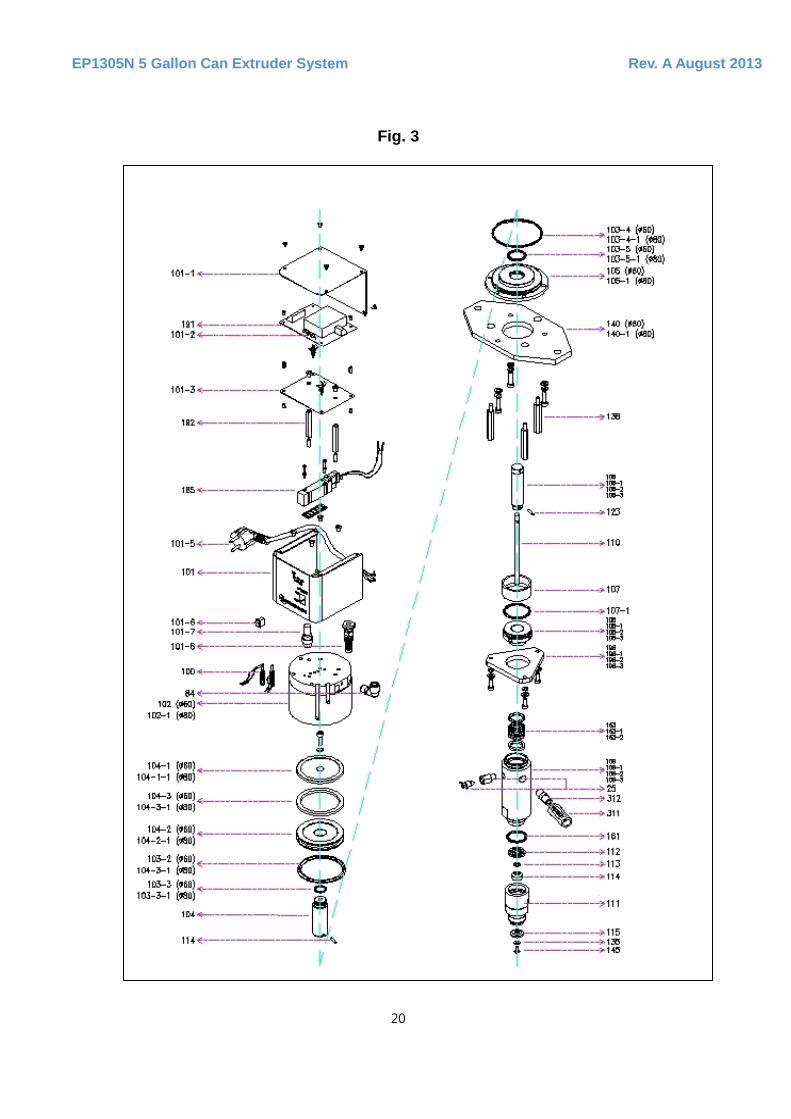
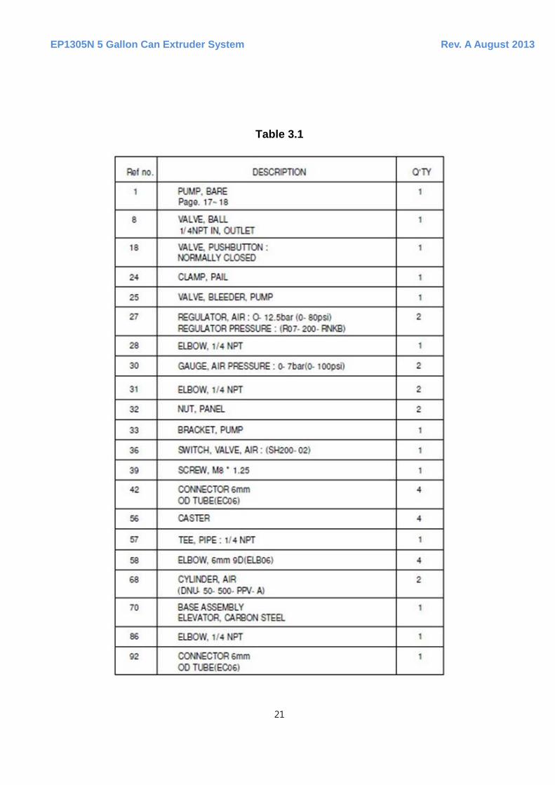
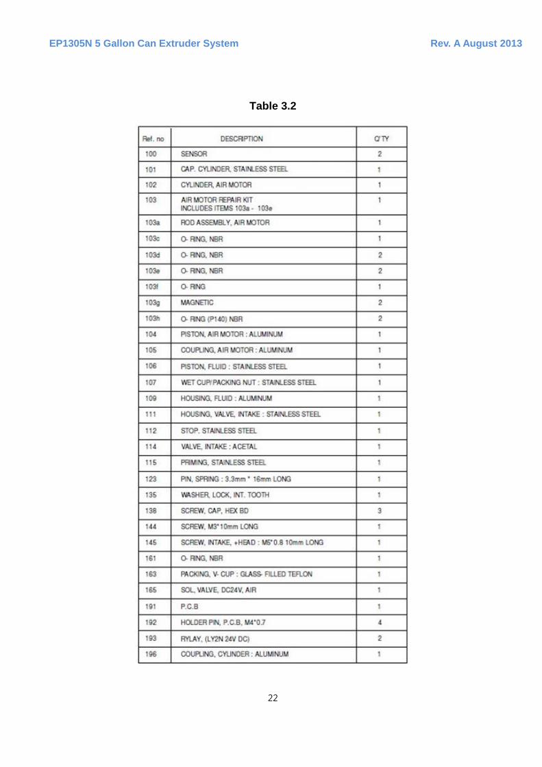
For this section, refer to Figure 3 and Table 3.1 and 3.2. to reference item part numbers in parentheses.
4.1 DISASSEMBLY
1. Disconnect the all hoses. Remove elbow at the fluid inlet however; do not operate the parts related to the air intake hole. First, disjoint the three screw bolts (138) and disjoint the bracket (33) at the upper part of pump after removing the washer. 2. After arranging the bleed valve (25-4) and the long hole of the bracket at the upper part of pump to be straight by turning the pump round, lift it up with the bracket immediately. NOTE. In case of exchanging the air valve (165), follow step 3. Otherwise, skip to step 4. 3. In case when the air valve (165) needs to be exchanged, remove the cylinder cap at the cylinder air motor. Remove the piping material and bolt connected to the air valve. After this, separate and remove the air valve. CAUCTION: Do not dip the air valve into the solvent. In case of cleaning the valve, use a brush or compressed air. 4. Remove 3 screw bolts (138) and washers connected to the coupling in the air operation area of cylinder (102). Pull out the cylinder by making the coupling straight until the piston (104) in the air valve housing is removed.

EP1305N 5 Gallon Can Extruder System Rev. A August 2013
14
5. Remove the pin (144) from the piston at the air motor (104) and the piston at the fluid area. Separate the piston at the air motor from the fluid piston. Remove the large ring placed at the outer area of air operation piston after pulling out the piston toward the air motor coupling (105). 6. Separate the air operation motor from the cylinder coupling (196). Pull out the coupling at the air motor area straight until the fluid piston (106) escapes from the coupling. Remove the O-ring (103c, 103e) from the coupling. 7. Hold the fluid piston (106) safely and remove the priming piston (115) and the priming piston rod (110) after disjointing the bolt and the washer by using the 4mm cross-shaped driver. 8. Pull out the priming piston rod (110) and the fluid piston assembly to the outside of fluid housing. Remove the pin (123) to separate the priming piston rod from the fluid piston. 9. Separate the O-ring after removing the valve intake housing (111) from the fluid housing. 10. Separate the intake valve (114) and the valve stop (112) from the valve intake housing. 11. Disjoint the wet-up / packing nut (107) and separate the v- cup packing from the neck area. 12. Clean the all parts with the solvent suitable for the fluid, and check for damage.
4.2 ASSEMBLY
NOTE. Lithium grease or a functional equivalent is suitable for lubricating moving parts of the pump. 1. Install the v- cup packing (163) in the neck of fluid housing (109). Connect the wet-cup/ packing nut (107) to the fluid housing after greasing the screw thread. 2. Connect the priming piston rod (110) to the fluid piston (106). Insert the pin (123) into the hole and carefully insert the piston and the rod connected by the wet-cup fluid housing. 3. Insert the valve stop (112) after carefully placing the intake valve into the intake housing. The valve stop (112) must be placed carefully on the front edge of the valve intake. Lubricate the O-ring (161). Carefully push the O-ring into the groove of the valve intake housing. 4. Grease the edge of fluid housing (109) screw. Insert the fluid housing and the valve intake housing (111) with the priming piston rod (110) by the valve stop and the intake valve (114) installed at the housing. Lock the valve intake housing in the fluid housing loosely. 5. Grease the screw thread, connect the bolt to the 4mm hole while holding the piston rod
EP1305N 5 Gallon Can Extruder System Rev. A August 2013
15
(106). Connect the priming piston (115) to the priming piston rod by using the screw and the washer. 6. Grease the screw thread of fluid housing (109). Connect the fluid coupling (196) of the fluid housing. 7. Insert large O-ring by placing it at the outside of the air motor coupling (105). 8. Align the air motor piston (104) with the lower part of fluid piston by the air motor coupling. Connect the air motor piston to the fluid piston to the edge of the screw thread by rotating it the proper direction. 9. Insert the large O-ring (103d) to the outer diameter of air motor piston (104). 10. Insert the magnetic holder, putting a magnet for censor on the assembled piston. Tighten the screw (103a). Grease the outer diameter of air motor piston assembly (104a) and on the inner wall of an air motor cylinder. 11. Align the air motor coupling (105) with the lower part of the motor cylinder (102). Lower in the air motor piston (104). Firmly connect the cylinder with the coupling with 3 bolts and washers. 12. If the air valve needs to be exchanged, install the upper part of air motor and the air valve in a straight alignment. And after disjointing the piping materials and exchanging it, assemble them in reverse order of disassembly. 13. Lower the pump by the mounting bracket (33). Reconnect the fluid outlet fitting (28) after firmly connecting the bracket by using 3 screw bolts and washer. 14. After reassembling the pad plate assembly to the fluid intake housing (111), reconnect it by using 2 cup screw bolts (30).
5. STORAGE
Clean the pump with the suitable solvent which must be specified by the material manufacturer before the fluid hardens.

EP1305N 5 Gallon Can Extruder System Rev. A August 2013
16
Section 4: FIGURES, TABLES AND GRAPHS

EP1305N 5 Gallon Can Extruder System Rev. A August 2013
17
MAIN UNIT

EP1305N 5 Gallon Can Extruder System Rev. A August 2013
18
Table 1
Fig. 1

EP1305N 5 Gallon Can Extruder System Rev. A August 2013
19
Fig. 2
EP1305N 5 Gallon Can Extruder System Rev. A August 2013
20
Fig. 3
EP1305N 5 Gallon Can Extruder System Rev. A August 2013
21
Table 3.1
EP1305N 5 Gallon Can Extruder System Rev. A August 2013
22
Table 3.2

EP1305N 5 Gallon Can Extruder System Rev. A August 2013
23
Fig. 4
Table 4

EP1305N 5 Gallon Can Extruder System Rev. A August 2013
24
Graph 1
EP1305N 5 Gallon Can Extruder System Rev. A August 2013
25
Section 5: TECHNICAL DATA

EP1305N 5 Gallon Can Extruder System Rev. A August 2013
26
6. TECHNICAL DATA
Maximum fluid dispensing pressure - - - - - - - - - - - - - - - - - - - - - - - - - - - - 996 psi Air pressure range input - - - - - - - - - - - - - - - - - - - - - - - - - - - - - - - - - 30-100 psi Maximum fluid viscosity - - - - - - - - - - - - - - - - - - - - - - - - - - - - - - - - - - 600,000 cps Dispensing volume per a stroke - - - - - - - - - - - - - - - - - - - - - - - - - - - - - - - - - - 0.01cc/Shot Maximum stroke - - - - - - - - - - - - - - - - - - - - - - - - - - - - - - - - - - - - - - - - - - - - - 19 mm Maximum temperature for operating the pump - - - - - - - - - - - - - - - - - - - - - - - - 50 C Air pressure inlet - - - - - - - - - - - - - - - - - - - - - - - - - - - - - - - - - - - - - - - - - - - - 6 mm Fluid outlet - - - - - - - - - - - - - - - - - - - - - - - - - - - - - - - - - - - - - - - - - - - - - - - - 3/8 npt Weight - - - - - - - - - - - - - - - - - - - - - - - - - - - - - - - - - - - - - - - - - - - - - - - - - - - - - 24 Kg
EP1305N 5 Gallon Can Extruder System Rev. A August 2013
27
Section 6: TROUBLESHOOTING GUIDE
EP1305N 5 Gallon Can Extruder System Rev. A August 2013
28
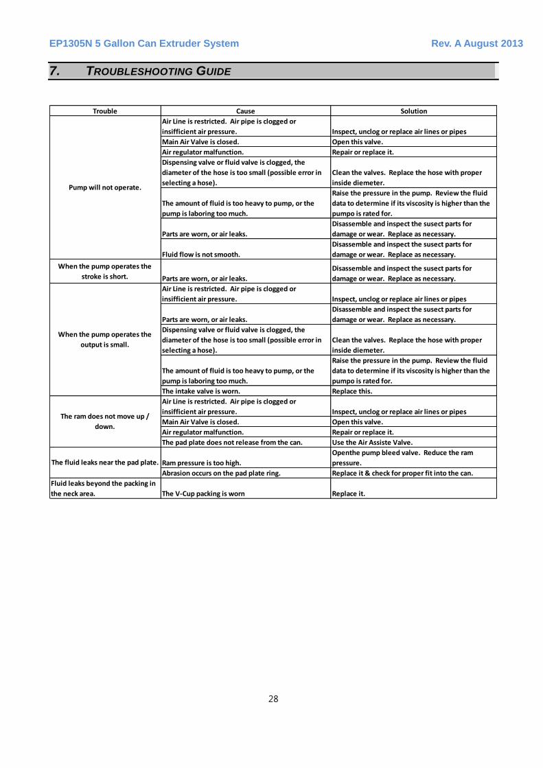
7. TROUBLESHOOTING GUIDE
Trouble Cause Solution
Air Line is restricted. Air pipe is clogged or
insifficient air pressure. Inspect, unclog or replace air lines or pipes
Main Air Valve is closed. Open this valve.
Air regulator malfunction. Repair or replace it.
Dispensing valve or fluid valve is clogged, the
diameter of the hose is too small (possible error in
selecting a hose).
Clean the valves. Replace the hose with proper
inside diemeter.
The amount of fluid is too heavy to pump, or the
pump is laboring too much.
Raise the pressure in the pump. Review the fluid
data to determine if its viscosity is higher than the
pumpo is rated for.
Parts are worn, or air leaks.
Disassemble and inspect the susect parts for
damage or wear. Replace as necessary.
Fluid flow is not smooth.
Disassemble and inspect the susect parts for
damage or wear. Replace as necessary.
When the pump operates the
stroke is short. Parts are worn, or air leaks.
Disassemble and inspect the susect parts for
damage or wear. Replace as necessary.
Air Line is restricted. Air pipe is clogged or
insifficient air pressure. Inspect, unclog or replace air lines or pipes
Parts are worn, or air leaks.
Disassemble and inspect the susect parts for
damage or wear. Replace as necessary.
Dispensing valve or fluid valve is clogged, the
diameter of the hose is too small (possible error in
selecting a hose).
Clean the valves. Replace the hose with proper
inside diemeter.
The amount of fluid is too heavy to pump, or the
pump is laboring too much.
Raise the pressure in the pump. Review the fluid
data to determine if its viscosity is higher than the
pumpo is rated for.
The intake valve is worn. Replace this.
Air Line is restricted. Air pipe is clogged or
insifficient air pressure. Inspect, unclog or replace air lines or pipes
Main Air Valve is closed. Open this valve.
Air regulator malfunction. Repair or replace it.
The pad plate does not release from the can. Use the Air Assiste Valve.
Ram pressure is too high.
Openthe pump bleed valve. Reduce the ram
pressure.
Abrasion occurs on the pad plate ring. Replace it & check for proper fit into the can.
Fluid leaks beyond the packing in
the neck area. The V-Cup packing is worn Replace it.
When the pump operates the
output is small.
Pump will not operate.
The ram does not move up /
down.
The fluid leaks near the pad plate.
EP1305N 5 Gallon Can Extruder System Rev. A August 2013
29