environmental impact statement · the environmental impact assessment regulations, 2007, ......
TRANSCRIPT

TN 159436
REMOVAL OF DUMPED MATERIAL & CONSTRUCTION OF INDUSTRIAL UNIT
FOR THE RECYCLING/TREATMENT OF WEEE, HHF 040, ĦAL FAR, QASAM
INDUSTRIJALI, BIRŻEBBUĠA
ENVIRONMENTAL IMPACT STATEMENT
Version 1: July 2015

i
Report Reference:
Adi Associates Environmental Consultants Ltd, 2015. Removal of Dumped
Material & Construction of Industrial Unit for the Recycling / Treatment of
WEEE, HHF 040, Ħal Far, Qasam Industrijali, Birżebbuġa. Environmental Impact Statement prepared in support of development application no. TN
159436. San Ġwann, 2015; xiii + 170 pp. + 2 Appendices + 3 Technical
Appendices.
THIS IS A DIGITAL COPY OF THE REPORT.
RESPECT THE ENVIRONMENT – KEEP IT DIGITAL

iii
This document has been prepared in accordance with the scope of Adi Associates’ appointment with its client and is subject to the terms of that appointment. It is addressed to and for the sole and
confidential use and reliance of Adi Associates’ client. Adi Associates accepts no liability for any use of this document other than by its client and only for the purposes for which it was
prepared and provided. Except as provided for by legislation, no person other than the client may copy (in whole or in part) use or rely on the contents of this document, without the prior written
permission of Adi Associates. Any advice, opinions, or recommendations within this document should be read and relied
upon only in the context of the document as a whole. The
contents of this document do not provide legal or tax advice or opinion.
© Adi Associates Environmental Consultants Ltd 2014
Kappara Business Centre 113 Triq Birkirkara
San Gwann SGN 4197
MALTA
Tel. / Fax: 21378172 - 77
Email: [email protected]
Web: www.adi-associates.com
This document has been prepared in accordance with the scope of Adi Associates’ appointment with its client and is subject to the terms of that appointment. It is addressed to and for the sole and
confidential use and reliance of Adi Associates’ client. Adi Associates accepts no liability for any use of this document other than by its client and only for the purposes for which it was
prepared and provided. Except as provided for by legislation, no person other than the client may copy (in whole or in part) use or rely on the contents of this document, without the prior written
permission of Adi Associates. Any advice, opinions, or recommendations within this document should be read and relied
upon only in the context of the document as a whole. The
contents of this document do not provide legal or tax advice or opinion.
© Adi Associates Environmental Consultants Ltd 2015
Kappara Business Centre 113 Triq Birkirkara
San Gwann SGN 4197
MALTA
Tel. / Fax: 21378172 - 77
Email: [email protected]
Web: www.adi-associates.com
Quality Assurance
Removal of dumped Material & Construction of Industrial Unit for the
Recycling/Treatment of WEEE, HHF 040, Ħal Far, Qasam Industrijali, Birżebbuġa Environmental Impact Statement
July 2015
Report for: Electronic Products Ltd
Revision Schedule
Rev Date Details Written by: Checked by: Approved by:
00 June 2015 Submission to Client Krista Farrugia Senior Environmental Consultant
Rachel Xuereb Director
Adrian Mallia Managing Director
File ref: G:\_Active Projects\EIA\WEE002 - WEEE Facility Hal Far\EIA\Final Chapters\MASTER
DOCUMENT\MASTER.docx


v
CONTRIBUTORS
Adi Associates Environmental Consultants Ltd prepared this Environmental Planning
Statement in association with the specialist consultants listed below:
Specialist Consultant: Topic responsible for:
Dr Saviour Scerri Geo-Environment
Adi Associates staff was involved in the following parts of this EIS:
Staff Member: Area responsible for:
Rachel Xuereb EIA Coordination/Review
Krista Farrugia EIA Coordination, Landscape and Visual Amenity, Ecology, Noise
Eilis McCullough Noise
Yury Zammit Landscape and Visual Amenity
Andrea Pace Land Use, Noise, Landscape and Visual Amenity
Rachel Decelis Environmental Risk Assessment

vi
CONSULTANTS’ DECLARATION
Adi Associates Environmental Consultants Ltd, Malta, prepared this Environmental Impact
Statement (EIS).
The Environmental Impact Assessment Regulations, 2007, Sections 28(3) and 29(1) require each
of the Consultants to declare that they carried out the study or part thereof, that they take
responsibility for statements and conclusions contained in their reports or part thereof, and
that they have no personal or financial interest in the proposed development.
We declare that Adi Associates Environmental Consultants Ltd has no personal or financial
interest in the proposed development.
Adi Associates Environmental Consultants Ltd has coordinated this EIS and has provided
technical input to specific parts of the Statement as identified in the previous page.
Adi Associates Environmental Consultants Ltd takes responsibility for statements and
conclusions contained in the parts of the report prepared directly by its staff. However,
statements made and conclusions drawn by the independent sub-consultants who prepared
the baseline studies reproduced in the Technical Appendices and which informed the
Environmental Statement remain the responsibility of the individual sub-consultants.
Adrian Mallia
Managing Director, Adi Associates

vii
The undersigned consultants / contributors / reviewers hereby declare that they carried out
the study or part thereof as identified on page v, that they have no personal or financial
interest in the proposed development and that they are not in any way associated with any
individual, company, association or grouping that has any direct or indirect, personal,
professional or financial interest in the abovementioned proposed development.
Dr Saviour Scerri
Rachel Xuereb
Krista Farrugia
Yury Zammit
Andrea Pace
Eilis McCullough
Rachel Decelis

viii
CONTENTS
1. Introduction ........................................................................................ 1
Background to the Scheme ....................................................................................................................... 1
Purpose of the EIS ....................................................................................................................................... 1
Structure of the EIS .................................................................................................................................... 2
2. EIA Methodology ................................................................................ 5
Introduction .................................................................................................................................................. 5
The EIA Process .......................................................................................................................................... 5 Terms of Reference .................................................................................................................................... 5
Method Statements ..................................................................................................................................... 5
EIA approach ................................................................................................................................................ 6
Significance of impacts ................................................................................................................................ 6
Uncertainty ................................................................................................................................................... 7
3. Description of Scheme and Site ........................................................ 9
Introduction .................................................................................................................................................. 9
Purpose and Objectives of the Scheme ................................................................................................. 9
Demand for the Scheme ............................................................................................................................ 9
Planning Policy Context for the Scheme ............................................................................................... 9
Structure Plan for the Maltese Islands .................................................................................................... 9
South Malta Local Plan ............................................................................................................................. 10
Site Description ......................................................................................................................................... 10
Scheme site ................................................................................................................................................. 10
Surrounding uses ....................................................................................................................................... 15
Scheme Description.................................................................................................................................. 21
Incoming waste and raw materials ........................................................................................................ 29 Waste treatment ....................................................................................................................................... 30
Scheme Construction ............................................................................................................................... 38
Construction activities ............................................................................................................................. 38
Timing .......................................................................................................................................................... 38
Raw materials ............................................................................................................................................. 38
Waste........................................................................................................................................................... 38
Machinery .................................................................................................................................................... 39
Emissions to air .......................................................................................................................................... 39
Scheme Operation .................................................................................................................................... 39
Emissions to air .......................................................................................................................................... 40
Resources ................................................................................................................................................... 41
Water and wastewater ............................................................................................................................ 45
Employment ................................................................................................................................................ 49

ix
Alternatives Considered .......................................................................................................................... 49
Alternative locations................................................................................................................................. 49
Alternative layouts and techniques ....................................................................................................... 49
4. Legislation and Policy Context........................................................ 51
Introduction ................................................................................................................................................ 51
International Legislation ........................................................................................................................... 51
The European Convention on the Protection of the Archaeological Heritage (Revised) ........ 51
European Policy and Legislation ............................................................................................................. 52
National Legislation .................................................................................................................................. 53
The Constitution of Malta ....................................................................................................................... 53
Environment and Development Planning Act 2010 (Act X of 2010) ............................................ 53
Environmental Management Construction Site Regulations, 2007 ................................................ 55
Legal Notices .............................................................................................................................................. 56
Malta Resources Authority Act 2001 ................................................................................................... 58
Planning Policy ............................................................................................................................................ 58
Structure Plan for the Maltese Islands 1990 ....................................................................................... 58
South Malta Local Plan, 2006 .................................................................................................................. 60
Development Control Policy and Design Guidance 2007 ............................................................... 65
Waste Management Plan for the Maltese Islands: A Resource Management Approach (2014 –
2020), January 2014 .................................................................................................................................. 65
Conclusion .................................................................................................................................................. 65
5. Geo-Environment ............................................................................. 67
Introduction ................................................................................................................................................ 67
Terms of Reference .................................................................................................................................. 67
Assessment Methodology ....................................................................................................................... 67
Standards and Policy Guidance .............................................................................................................. 67
Area of Influence ....................................................................................................................................... 68
Geo-environment Methodology ............................................................................................................ 75
Baseline: Geology ...................................................................................................................................... 75
Stratigraphy ................................................................................................................................................. 75 Lower Coralline Limestone Formation ................................................................................................ 76
Structural Geology .................................................................................................................................... 77
Stone material to be excavated ............................................................................................................. 77
Baseline: Geomorphology ....................................................................................................................... 78
Cliff coastline .............................................................................................................................................. 78
Ħal Far plain ................................................................................................................................................ 79
Soil ................................................................................................................................................................ 79
Baseline: Hydrogeology............................................................................................................................ 83
Mean Sea Level Aquifer ........................................................................................................................... 83
Wied Żnuber watercourse ..................................................................................................................... 83
Wied il-Mixta and site catchments ........................................................................................................ 83
Water boreholes ....................................................................................................................................... 83
Surface run-off estimates ......................................................................................................................... 84

x
Assessment of Impacts ............................................................................................................................. 87
Impact significance ..................................................................................................................................... 87
Prediction and significance of impacts .................................................................................................. 87
Mitigation .................................................................................................................................................... 88
Residual Impacts ........................................................................................................................................ 88
6. Landscape and Visual Amenity ....................................................... 91
Introduction ................................................................................................................................................ 91
Terms of Reference .................................................................................................................................. 91
Objectives of the Assessment ................................................................................................................ 91
Legislation and Policies Guidance .......................................................................................................... 92
Standards and guidelines .......................................................................................................................... 93
Assessment Methodology ....................................................................................................................... 93
Desk study methodology......................................................................................................................... 93
Visual amenity: Zone of Theoretical Visibility ................................................................................. 107
Changes in the Landscape and Visual Amenity ................................................................................ 108
Changes in the landscape and their significance .............................................................................. 109
Changes in visual amenity and their significance ............................................................................. 109
7. Ecology ............................................................................................ 117
Introduction ............................................................................................................................................. 117
Methodology ........................................................................................................................................... 117
Assessment objectives .......................................................................................................................... 117
Assessment Methodology .................................................................................................................... 123
Baseline survey results .......................................................................................................................... 123
Land cover & vegetation assemblages ............................................................................................... 123
Fauna ......................................................................................................................................................... 123
Impact Assessment ................................................................................................................................ 127
Potential impacts .................................................................................................................................... 127
Prediction and significance of impacts ............................................................................................... 127
Mitigation ................................................................................................................................................. 127
8. Noise ................................................................................................ 131
Introduction ............................................................................................................................................. 131
Standards and Guidance ....................................................................................................................... 131
Baseline Noise Survey ........................................................................................................................... 131
Description of the area in the vicinity of the Scheme Site ........................................................... 131
Baseline survey methodology .............................................................................................................. 132
Eastings ................................................................................................. 135
Northings .............................................................................................. 135
Construction Noise ............................................................................................................................... 137
Construction phasing ............................................................................................................................ 137
Methodology for predicting construction noise levels .................................................................. 138

xi
Predicted noise levels arising from construction of the Scheme ................................................ 139
Operational Noise ................................................................................................................................. 139
Description of the operational noise sources ................................................................................. 139
Predicted noise levels arising from the Scheme in operation ...................................................... 141
Assessment of Impacts .......................................................................................................................... 141
Construction noise: significance criteria ........................................................................................... 141
Prediction and significance of construction impacts ...................................................................... 142
Operational noise: significance criteria ............................................................................................. 143
Prediction and significance of operational impacts ......................................................................... 144
Mitigation ................................................................................................................................................. 145
Residual Impacts ..................................................................................................................................... 145
9. Environmental Risk Assessment ................................................... 149
Introduction ............................................................................................................................................. 149
Terms of Reference ............................................................................................................................... 149
Assessment Methodology .................................................................................................................... 149
Scheme phases ........................................................................................................................................ 149
Objectives ................................................................................................................................................ 149
Methodology ........................................................................................................................................... 150
Risk assessment criteria ........................................................................................................................ 151
Risk Assessment ..................................................................................................................................... 152
Overview.................................................................................................................................................. 152
Identification of potential releases ..................................................................................................... 159
Identification of migration pathways .................................................................................................. 159
Identification of potential receptors .................................................................................................. 161
Risk evaluation ........................................................................................................................................ 162
Conclusion and recommendations ..................................................................................................... 166
10 Summary of key impacts, interaction between impacts and
mitigation ........................................................................................ 167
Introduction ............................................................................................................................................. 167
Summary of Key Impacts ...................................................................................................................... 167
Interaction of Impacts ........................................................................................................................... 167
Cumulative Impacts ............................................................................................................................... 168
Mitigation ................................................................................................................................................. 168
Appendix 1: A3 Photographs .............................................................. 171
Appendix 2: Archaeological investigation terms of reference ......... 177
FIGURES Figure 1.1: Location of the Scheme ......................................................................................................... 3
Figure 3.1: Scheme Site ........................................................................................................................... 13

xii
Figure 3.2: Surrounding land uses ......................................................................................................... 17
Figure 3.3: Adjacent properties to the Scheme................................................................................. 19
Figure 3.4: Agricultural fields to the southeast of the Scheme ...................................................... 19
Figure 3.5: Southern Shooting Club shooting range ......................................................................... 19
Figure 3.6: Concrete batching plants ................................................................................................... 20
Figure 3.7: Various industrial uses ........................................................................................................ 20
Figure 3.8: Open air storage .................................................................................................................. 20
Figure 3.9: Electricity substations ......................................................................................................... 21
Figure 3.10: Scheme layout .................................................................................................................... 25
Figure 3.11: Scheme plans (central building) and sections .............................................................. 27
Figure 3.12: Main crusher ....................................................................................................................... 31
Figure 3.13: Cable crusher ..................................................................................................................... 31
Figure 3.14: Fluorescent tube crusher ................................................................................................. 32
Figure 3.2: Proposed outdoor lighting plan ........................................................................................ 43
Figure 3.16: Surface water and wastewater management ............................................................... 47
Figure 4.1: Ħal Far Industrial Estate area policy map (South Malta Local Plan) ......................... 63
Figure 5.3: Geology and geomorphology Area of Influence ........................................................... 69
Figure 5.2: Hydrology and hydrogeology Area of Influence ........................................................... 71
Figure 5.3: Location of boreholes ......................................................................................................... 73
Figure 5.4: Geological map of the Area of Influence (OED, 1993) ............................................... 81
Figure 5.5: Hydrology and hydrogeology ............................................................................................ 85
Figure 6.1: Zone of Visual Influence and selected viewpoints ........................................................ 99
Figure 6.2: Landscape Character Areas and Local Landscape Tracts ......................................... 101
Figure 7.1: Area of Influence ................................................................................................................ 121
Figure 7.2: Disturbed ground (Application Site) supporting ruderal species ............................ 124
Figure 7.3: Ruderal community growing in area adjacent to the Scheme site ......................... 124
Figure 7.4: Ecology survey results ...................................................................................................... 125
Figure 8.1: Noise Monitoring Point and Noise Sensitive Receptors .......................................... 133
Figure 9.1: Example source-pathway-receptor model ................................................................... 151
TABLES Table 3.1: Incoming waste ...................................................................................................................... 29
Table 3.2: Raw materials ......................................................................................................................... 30
Table 3.3: Syngas composition .............................................................................................................. 33
Table 3.4: Outgoing waste ..................................................................................................................... 35
Table 3.5: Raw materials to be used during construction .............................................................. 38
Table 3.6: Construction waste .............................................................................................................. 39
Table 3.7: Energy consumption ............................................................................................................. 41
Table 3.8: Energy generation ................................................................................................................. 41
Table 5.1: Summary of Impacts on the Geo-environmental Resources ...................................... 89

xiii
Table 6.1: Landscape character sensitivity .......................................................................................... 94
Table 6.2: Magnitude of change to landscape resource ................................................................... 95
Table 6.3: Magnitude of visual change.................................................................................................. 96
Table 6.4 Landscape Receptors ............................................................................................................ 97
Table 6.5 Identification of Impact Significance ................................................................................. 105
Table 6.6: Landscape Character Types and Landscape Character Areas .................................. 106
Table 6.7: Summary of Application Site visibility from viewpoints ............................................. 108
Table 6.8 Changes in landscape character and the significance of the impacts ........................ 109
Table 6.9: Summary of Impacts on Landscape and Visual Amenity ........................................... 115
Table 8.1: Location of Noise Monitoring Points ............................................................................. 135
Table 8.2: Sound Level Surveys ........................................................................................................... 135
Table 8.3: Baseline Sound Level Measurements .............................................................................. 137
Table 8.4: Excavation Plant / Equipment and Relevant Sound Levels ......................................... 138
Table 8.5: Predicted Noise Generated from Excavation during the Construction of the
Scheme ............................................................................................................................................. 139
Table 8.6: Operational Plant / Equipment and Relevant Sound Levels ...................................... 140
Table 8.7: Predicted Noise Generated from the Scheme in Operation .................................... 141
Table 8.8: BS 4142:2014 Assessment criteria .................................................................................. 143
Table 8.9: Summary of noise impacts ................................................................................................ 147
Table 9.1: Criteria for assessing environmental consequences ................................................... 152
Table 9.2: Measure of likelihood ......................................................................................................... 152
Table 9.3: Risk matrix............................................................................................................................ 152
Table 9.4: Pollution pathway identification and mitigation measures ......................................... 155
Table 9.5: Pollution pathway identification and mitigation measures for major accident
scenarios .......................................................................................................................................... 157
Table 9.6: Risk levels without mitigation .......................................................................................... 162
Table 9.7: Risk levels with mitigation ................................................................................................. 163
Table 10.1: Summary of impacts ......................................................................................................... 169
APPENDICES
Appendix 1: A3 Photographs
Appendix 2: Archaeological Investigation Terms of Reference

1
1. INTRODUCTION
1.1. This Environmental Impact Statement (EIS) was commissioned by Electronic Products
Ltd, to support its proposal for the construction of an industrial unit for the
recycling/treatment of waste electrical and electronic equipment (WEEE).
1.2. Following the submission of a Project Description Statement (PDS) for the proposed
development in November 2014, the Malta Environment and Planning Authority
(MEPA) determined that the development required an EIS, in accordance with
Schedule 1A, Category I Sections 2.7.1.1, of the Environmental Impact Assessment
Regulations, 2007 (Legal Notice 114 of 2007).
1.3. Hereafter in this EIS, the proposed development is referred to as ‘the Scheme’. The
Scheme site boundary is illustrated in Figure 1.1. A full description of the Scheme is
provided in Chapter 3 of the EIS.
BACKGROUND TO THE SCHEME
1.4. The Applicant has been carrying out his current operations from three garages
located in the Ta’ Maġġi Industrial Zone in Żabbar. Current operations include the receipt of WEEE, separation of components through use of a main crusher (used for
non-hazardous waste) and a cable crusher to separate the metal wiring from the
plastic case thus facilitating recycling.
1.5. The Applicant intends to expand current operations to include the use of a
fluorescent tube crusher for the processing of fluorescent tubes and lamps, which
constitute hazardous waste and which would, therefore, require the installation of an
appropriate abatement system for air emissions and waste water.
1.6. In addition, the Applicant stores over 50 tonnes of WEEE at his facility, qualifying his
operation for an Integrated Pollution and Prevention Control permit in accordance
with the Industrial Emissions Directive and Legal Notice 10 of 2013, Industrial
Emissions (Integrated Pollution Prevention and Control) Regulations, 2013. Given
this requirement, the Applicant intends to develop his new facility to operate in line
with IPPC permit conditions.
PURPOSE OF THE EIS
1.7. The purpose of this EIS is to present the findings of the Environmental Impact
Assessment (EIA). EIA is the process of systematically assessing the likely significant
environmental impacts of the proposals. EIA also ensures that the significance of
these impacts, and the scope for reducing them, is clearly understood by both the
public and by MEPA before a decision is made on whether or not the proposal
should be approved.

2
STRUCTURE OF THE EIS
1.8. Following this introduction, the EIS is structured as follows:
Chapter 2: EIA Methodology
Chapter 3: Description of Site and Scheme
Chapter 4: Legislation and Policy Context
Chapter 5: Geo-environment
Chapter 6: Landscape and Visual Amenity
Chapter 7: Ecology
Chapter 8: Noise
Chapter 9: Environmental Risk Assessment
Chapter 10: Key Impacts, Cumulative Effects and Summary of Mitigation
Appendix 1: Baseline Photos and Photomontages
Appendix 2: Archaeological Investigation Terms of Reference
1.9. The EIS also contains the following Technical Appendices (compiled separately as
Volume 2 of the EIS):
Technical Appendix 1: Terms of Reference and Method Statements
Technical Appendix 2: Geo-Environment Baseline Report
Technical Appendix 3: Noise Baseline Report
1.10. The EIS includes a Non Technical Summary in Maltese and English.

3
Figure 1.1: Location of the Scheme


5
2. EIA METHODOLOGY
INTRODUCTION
2.1. This chapter sets out the broad methodology that was used in the Environmental
Impact Assessment (EIA) of the Scheme. It sets out the key stages that were
followed, in line with EIA best practice. The chapter also explains how the
significance of impacts was assessed, and how this was a consistent process
throughout the EIA.
THE EIA PROCESS
2.2. The current guidance on the EIA process is contained in the Environmental Impact
Assessment (EIA) Regulations, 2007. The Malta Environment and Planning Authority
(MEPA) has directed that an Environmental Impact Statement (EIS) be prepared for
Scheme.
Terms of Reference
2.3. The Terms of Reference (ToR) for the EIA were prepared by MEPA in consultation
with the relevant Government Departments. The final version of the ToR is included
in Technical Appendix 1: Terms of Reference and Method Statements.
2.4. The ToR were formulated following a scoping exercise, undertaken by MEPA, to
identify the issues to be considered in the EIA. The ToR focused on those impacts of
the Scheme considered by MEPA to be significant and, therefore, requiring further
assessment, and avoiding the examination of all potential environmental impacts. The
ToR also outlined the various components of the EIA.
Method Statements
2.5. As required by the EIA Regulations, all the Consultants involved in this EIS were
approved by MEPA.
2.6. Method Statements were prepared in respect of the topic areas: geo-environment;
landscape and visual amenity; ecology; and noise. The Method Statements
addressed the following:
Introduction, listing the objectives of the study and reference to the ToR;
Details of baseline survey methodology;
Description of the Area of Influence and sensitive receptors;
Field survey methodology, as relevant;
Analytical methodology;
Evaluation of data;
Identification of impacts;

6
Prediction of impacts;
Impact significance; and
Mitigation.
2.7. All Method Statements were accepted by MEPA, and were subsequently used as the
basis for carrying out the individual baseline surveys. The accepted Method
Statements are included in Technical Appendix 1: Terms of Reference & Method
Statements.
EIA approach
2.8. Good practice necessitates that EIA be treated as an iterative process, rather than a
one-off, post-design environmental appraisal. In this way, the findings from the EIA
can be fed into the design process, leading to the production of a more
environmentally sensitive project. This approach was adopted for this EIA.
2.9. Baseline surveys for the specialist EIA topics were undertaken by the Consultants
based on the Area of Influence (AoI) and sensitive receptors agreed with MEPA for
each topic area. A detailed assessment of the Scheme’s impact on the features
present within the AoI and on the sensitive receptors was undertaken, and any
potential environmental benefits of the Scheme identified.
Significance of impacts
2.10. Assessment of the significance of impacts arising from the Scheme is a key stage in
the EIA process. This judgement is critical in informing the decision-making process.
However, defining significance can be difficult. In general terms, environmental
significance involves assessing the amount of change to the environment perceived to
be acceptable to the community (Sippe, 1999).
2.11. The following criteria were used in this EIA to assess the significance of an impact:
Type of impact (adverse / beneficial);
Extent and magnitude of impact;
Direct or indirect impact;
Duration of impact (short term / long term; permanent / temporary);
Comparison with legal requirements, policies and standards;
Sensitivity of receptor (residential dwellings, hotels, recreational areas, etc.);
Probability of impact occurring (certain, likely, uncertain, unlikely, remote);
Reversibility of impact;
Scope for mitigation / enhancement (very good, good, none); and

7
Residual impacts.
2.12. Using these criteria, the significance of the impacts arising from the Scheme was
categorised in the EIS, as follows:
Not significant;
Minor significance; and
Major significance.
2.13. An additional criterion, describing moderate significance was included for the
landscape and visual, as well as the noise assessments, as was considered appropriate
in line with the changes being described.
2.14. Definitions of the meaning of the ‘significance categories’ above in relation to each topic area are included in the topic area chapters (see Chapter 5 to Chapter 9).
However, in general terms, if an impact is ‘not significant’, it is considered to be
environmentally acceptable; an impact of ‘minor significance’ refers to an impact that
is considered to be manageable; and an impact of ‘major significance’ refers to an
impact that is considered to be environmentally damaging such as to require that the
Scheme be redesigned, or that mitigation measures be put in place to minimise the
impact. For a definition of moderate significance in terms of landscape and visual
assessment and noise, refer to Chapter 6 and Chapter 8. However, in general
terms, it is considered that a noise impact of ‘moderate significance’ refers to an
impact that may be manageable in certain circumstances, although is likely to require
implementation of suitable mitigation measures to minimise the impact as far as
possible ensuring that the residual impact is lower than the predicted outcome.
2.15. The EIS includes an assessment of the significance of predicted impacts and, following
the implementation of any proposed mitigation measures, the significance of any
residual impacts. A summary of the identified significant impacts is included in
Chapter 10. The recommended mitigation measures, and residual impacts, are
described in respect of each topic area, at the end of the relevant chapter (see
Chapter 5 to Chapter 9).
UNCERTAINTY
2.16. The EIA process is designed to enable good decision-making based on the best possible information about the environmental implications of a proposed
development. However, there will always be some uncertainty as to the exact scale
and nature of the environmental impacts. This arises through shortcomings in
information, doubts, or lack of certainty on the likelihood that an incidence would
occur, and / or due to the limitations of the prediction process itself. Where
uncertainties have arisen, and where they remain, this is clearly stated in the EIS.


9
3. DESCRIPTION OF SCHEME AND SITE
INTRODUCTION
3.1. This chapter describes the Scheme. It explains the purpose and justification for the
Scheme and includes a description of the Scheme site and its surroundings.
PURPOSE AND OBJECTIVES OF THE SCHEME
3.2. The primary objective of the Scheme is to provide a facility for the preparation for
recovery of WEEE.
3.3. The Scheme aims to:
Develop a new purpose-built WEEE treatment facility that is equipped with air
abatement, surface water management and pollution prevention measures;
Facilitate Malta’s achievement of the minimum WEEE collection rate and WEEE recovery targets set by the Waste Management Plan for the Maltese Islands
(2014-2020) and Legal Notice 204 of 2014, the Waste Management (Electrical
and Electronic Equipment) Regulations.
DEMAND FOR THE SCHEME
3.4. In receiving and processing waste from electrical and electronic equipment resulting
in an output that can largely be reused, recycled or recovered, the Scheme is directly
contributing to a national collection rate of WEEE by 2021 and national reuse,
recycling and recovery targets for 2018 set out in the Waste Management Plan for
the Maltese Islands: A Resource Management Approach (2014-2020) as discussed in
Chapter 4.
PLANNING POLICY CONTEXT FOR THE SCHEME
3.5. The Scheme is generally in line with national and planning policy, specifically: the
Structure Plan for the Maltese Islands 1990 and the South Malta Local Plan 2006.
3.6. The relevant sections of these policy documents are explained in detail in Chapter 4
of the EIS; however, the planning policy justification for the Scheme is summarised
below.
Structure Plan for the Maltese Islands
3.7. Structure Plan POLICY SET 10 identifies Ħal Far as an area within which major
development will be undertaken also as identified in POLICY IND 1.
3.8. The Structure Plan also provides a basis for regulating the built environment and
development generally. POLICY BEN 1 and POLICY BEN 2 provide that
development should not have a deleterious impact on its surroundings. POLICY
BEN 12 provides for the request by MEPA of an EIA, in order to determine the
impacts of a development and to mitigate any possible negative impacts.

10
South Malta Local Plan
3.9. The Scheme site lies within the Ħal Far Industrial Estate. POLICY SMHF01 concerns the industrial development boundary and seeks to also ensure the
upgrading and improvement of the industrial development zone and ensure that
negative environmental impacts are kept to a minimum and environmental
considerations included during development application stage through the use of EIA
and or TIS as appropriate.
SITE DESCRIPTION
Scheme site
3.10. The Scheme site covers an area of approximately 1,600 m2. The site is located close
to the eastern boundary of the Ħal Far Industrial Estate. Access is through a wide
surfaced road.
3.11. The site is currently unused, disturbed land. The site surface is covered in
construction / demolition waste and the area is overgrown with vegetation.
3.12. The site used to form part of the taxiway / park at the former Ħal Far airfield, which
operated between the 1920s and the 1970s.
3.13. Figure 1.1 (Chapter 1) shows the Scheme site location. Figure 3.1 illustrates the
site as it was at the start of the planning application process.
Archaeological value
3.14. On issuance of the EIA Terms of Reference (by MEPA), the Applicant was also issued
with Terms of Reference for site investigation from an archaeological perspective by
the Superintendence of Cultural Heritage (SCH). The latter Terms of Reference
required the Applicant to remove the construction/demolition waste from the
Scheme site. Soil removal was also required, in the constant presence of an
approved archaeologist. The SCH’s Terms of Reference had also referred to the need for site excavation. However, SCH later indicated that soil removal would
provide sufficient indication at this stage of whether the site is of archaeological
importance.
3.15. As per the Terms of Reference issued by the Superintendence of Cultural Heritage
on the 23rd April 2015, an archaeological investigation was requested in order to
determine the cultural importance of HHF040, Ħal-Far (refer to Appendix 2 for ToR). The investigation commenced in February and was completed in June 2015.
Any modern rubble or vegetation was removed in order to allow the monitor to
carry out a field survey. From the field survey, the monitor retrieved one piece of
non diagnostic pottery shard and one piece of bone. Following this process, the site
was divided into Area A and Area B. In Area A, only sterile soil was removed and the
uncovered bedrock was very friable. No features or archaeological deposits were
noted in this area. In Area B, only sterile soil was removed. As this area has different gradients in the rock contours, the client opted to clean three sub areas (instead of
brushing the entire area) as works had to be carried out manually. The monitor

11
inspected these three sub areas and no features were noted. All the necessary
documentation has been submitted to Superintendence.


13
Figure 3.1: Scheme Site


15
Surrounding uses
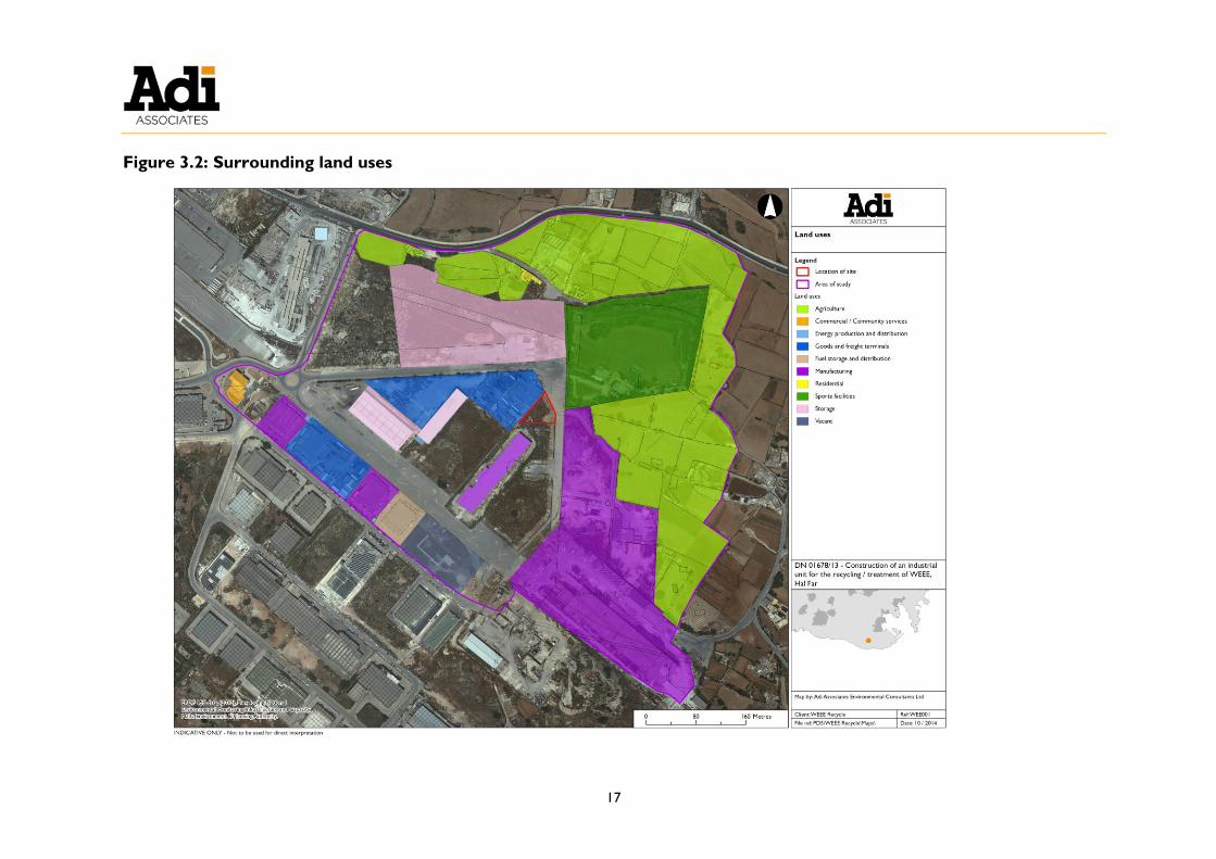
3.16. A land use survey was carried out in October 2014 (refer to Figure 3.2). The
primary land uses in the area around the Scheme site are industrial and agricultural.
3.17. The Scheme site is located in a block surrounded by two wide roads. This block is
composed of unused and disturbed land, storage areas including a container depot,
and a steel manufacturing facility (refer to Figure 3.3). Access to another road
south of the Scheme was blocked by trailers during the survey.
3.18. Agricultural fields dominate the north and eastern boundaries of the area of study.
There is also a residence around 170 m north of the Scheme site (refer to Figure
3.4).
3.19. The Southern Shooting Club shooting range is found immediately to the northeast of
the Scheme, on the other side of the road (refer to Figure 3.5). To the southeast
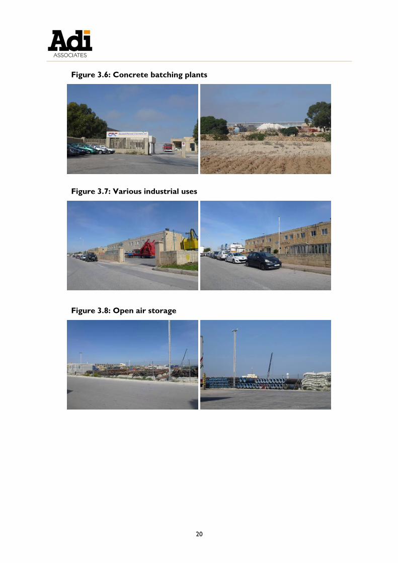
of the Scheme, concrete batching plants cover an extensive area of land (refer to
Figure 3.6).
3.20. A mix of industries is located southwest of the Scheme site: pharmaceuticals,
transportation, manufacturing and oil-related activities (refer to Figure 3.7). A
vacant unit is still under construction. It is unclear whether an existing building in this
area is already in use.
3.21. The area northwest of the Scheme site is characterised by unused land and a large
open-air storage area for metal structures (rods and tubes) (refer to Figure 3.8).
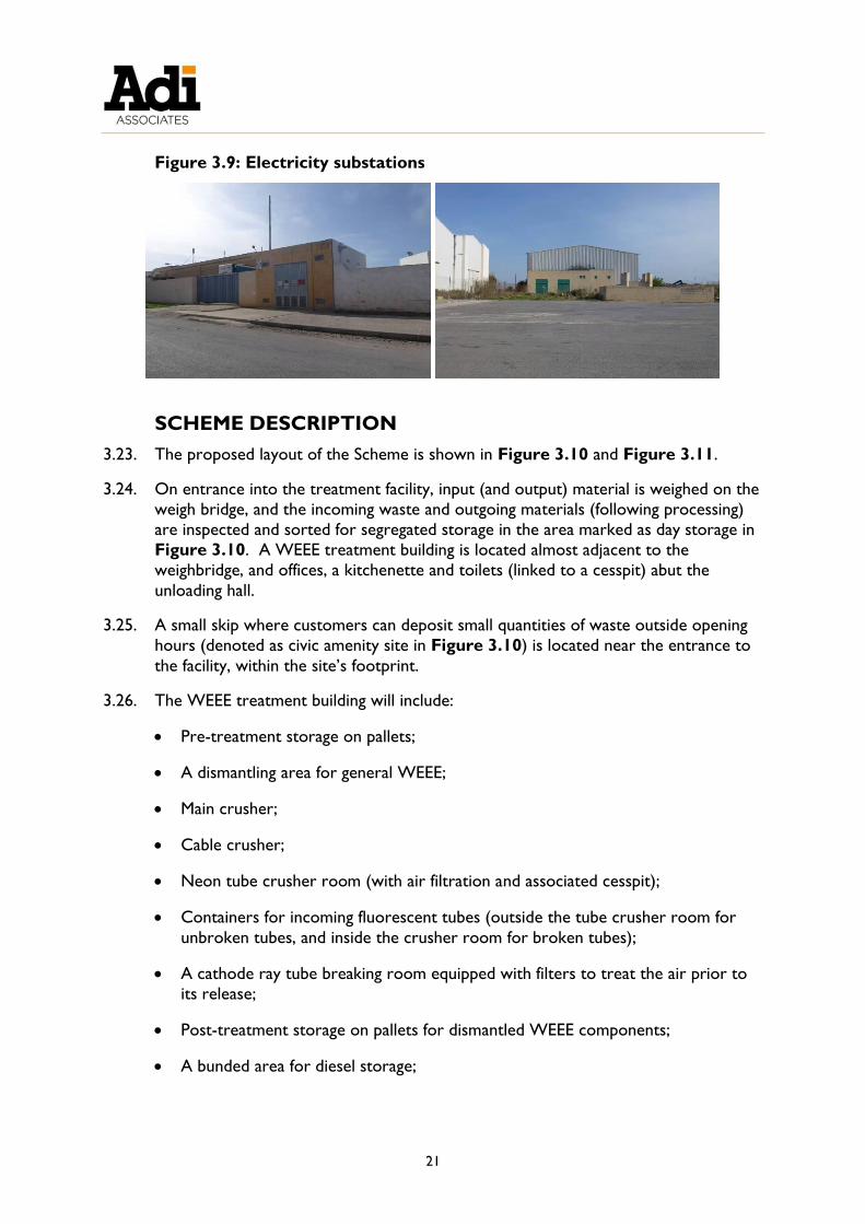
3.22. A number of electricity substations are also scattered over the area of study (refer to Figure 3.9). The ones visible during the survey have been mapped; however, there
may also be other substations within individual facilities that are not visible from the
road.

17
Figure 3.2: Surrounding land uses


19
Figure 3.3: Adjacent properties to the Scheme
Figure 3.4: Agricultural fields to the southeast of the Scheme
Figure 3.5: Southern Shooting Club shooting range
20
Figure 3.6: Concrete batching plants
Figure 3.7: Various industrial uses
Figure 3.8: Open air storage
21
Figure 3.9: Electricity substations
SCHEME DESCRIPTION
3.23. The proposed layout of the Scheme is shown in Figure 3.10 and Figure 3.11.
3.24. On entrance into the treatment facility, input (and output) material is weighed on the
weigh bridge, and the incoming waste and outgoing materials (following processing)
are inspected and sorted for segregated storage in the area marked as day storage in
Figure 3.10. A WEEE treatment building is located almost adjacent to the
weighbridge, and offices, a kitchenette and toilets (linked to a cesspit) abut the
unloading hall.
3.25. A small skip where customers can deposit small quantities of waste outside opening
hours (denoted as civic amenity site in Figure 3.10) is located near the entrance to
the facility, within the site’s footprint.
3.26. The WEEE treatment building will include:
Pre-treatment storage on pallets;
A dismantling area for general WEEE;
Main crusher;
Cable crusher;
Neon tube crusher room (with air filtration and associated cesspit);
Containers for incoming fluorescent tubes (outside the tube crusher room for
unbroken tubes, and inside the crusher room for broken tubes);
A cathode ray tube breaking room equipped with filters to treat the air prior to
its release;
Post-treatment storage on pallets for dismantled WEEE components;
A bunded area for diesel storage;

22
Battery storage bins; and
A waste oil tank.
3.27. A covered shed for storage is located at the back of the facility; the shed will also be
used for basic maintenance of site vehicles. The gasification unit is also located in this
area.
3.28. A fleet parking area as well as parking for staff and customers is available within the
Scheme footprint.
3.29. The Scheme is mainly intended for the storage and treatment of the following WEEE
categories:
Medium-sized household appliances including microwave ovens, electric fans and
electric radiators;
Small household appliances including toasters, irons, vacuum cleaners and
hairdryers;
IT and telecommunications equipment including computers, servers,
photocopiers, mobile phones, printers, and facsimile machines;
Cathode ray tube (CRT) monitors and liquid crystal displays (LCDs);
Consumer electronics including DVD players, hi-fi equipment, electric guitars,
amplifiers, radios and cameras;
CRT TVs and flat-panel TVs;
Fluorescent and neon tubes / lights;
Electrical and electronic tools including drills, electric saws, sewing machines,
lawnmowers, sanders, nail guns, etc;
Toys, leisure and sports equipment including video game consoles, electronic
fitness equipment, electric trains and car racing systems, coin slot machines, etc;
Medical devices including analysers, imaging and radio therapy equipment;
Monitoring and control instruments including smoke detectors and thermostats;
and
Automatic dispensers including cold drinks and snacks dispensers, and cash
machines.
3.30. Batteries will also be accepted for storage prior to export.
3.31. In addition, the Scheme will operate a gasification plant for treatment of wood. The
Scheme will also involve shredding clean wood waste to generate a product that can

23
be used for animal bedding or briquettes; the latter wood treatment option will be
used until the gasification plant is commissioned and / or to act as a backup for the
gasification plant.
3.32. Olea europaea trees will be planted in order to landscape the site as shown in Figure
3.10.


25
Figure 3.10: Scheme layout


27
Figure 3.11: Scheme plans (central building) and sections


29
Incoming waste and raw materials
3.33. Table 3.1 identifies the wastes to be accepted on site and the treatment method
proposed.
Table 3.1: Incoming waste
EWC
code
H-code1 Description Estimated annual
quantities
Treatment
16 02 13*
16 02 14
16 02 15*
16 02 16
08 03 17* 2
08 13 18
09 01 10
09 01 11*
09 01 12
20 01 35*
20 01 36
H5, H14 WEEE and WEEE
components / parts
500 tonnes Manual dismantling, crushing
of cables and non-hazardous
components
16 02 13*
20 01 35*
H5, H14 CRT televisions and
monitors
300 tonnes Dismantled and broken in
CRT breaking room,
gasification of wooden
components (e.g. from old
TVs)
16 02 13*
20 01 21*
H5/6,
H14
Fluorescent tubes
and bulbs
30 tonnes Crushed in crusher room
(after removing from
housing, where applicable)
16 02 11*
16 02 13*
20 01 23*
H5, H14 Fridges / freezers 200 tonnes Storage prior to export
16 06 01*
16 06 02*
16 06 03*
16 06 04
20 01 33*
20 01 34
H5/6, H8,
H14
Batteries 50 tonnes Storage prior to export
15 01 01
15 01 02
15 01 06
- WEEE-related
packaging
25 tonnes Segregated from WEEE and
sent to an authorised
recycling facility
03 01 04*
03 01 05
15 01 03
17 02 01
19 12 06*
19 12 07
20 01 37*
20 01 38
H3, H5 Wood items (e.g.
pallets, offcuts,
wooden packaging
from old TVs)
100 tonnes Gasification;
Non-hazardous wood may
alternatively be shredded
and sold for use as animal
bedding / briquettes
1 Applicable only when the waste is hazardous. 2 Referring to toner cartridges.

30
3.34. The principal raw materials during operation are identified in Table 3.2.
Table 3.2: Raw materials
Raw
material
Associated activity Maximum
quantity stored
on site
Storage location and containment
Diesel Operation of on-site
forklifts and trucks
50 L Stored in drums in a locked and
bunded shed; the bund capacity will be
at least 110% of the total materials
stored inside it.
Engine start
formula
Operation of an older
truck (assists with cold
diesel engine start-up)
500 mL Locked and bunded shed; the bund
capacity will be at least 110% of the
total materials stored inside it.
LPG Operation of a forklift
truck
25 kg Cylinder inside the main building,
against a wall next to the waste oils
tank.
Hydraulic
oil
Maintenance of on-site
forklifts and trucks
25 L Stored in a drum in a locked and
bunded shed.
Charcoal Start-up of gasification
plant
100 kg Covered shed close to the gasification
plant.
Waste treatment
WEEE processing
3.35. Treatment of each WEEE stream will be carried out in accordance with a MEPA-
approved work plan. In general, the process will involve the following steps:
Receipt of goods and storage in a designated area;
Manual dismantling and segregation of components into different waste streams;
Crushing of certain components using one of three crushers, as described in
further detail below; and
Storage of each waste stream, segregated by type, in designated areas prior to
transfer to authorised facilities, locally or abroad.
3.36. Manual dismantling and segregation of components will be carried out in the
dismantling area identified in Figure 3.11, with the exception of CRT monitors and
TV sets, which will be dismantled in the purpose-built CRT breaking room.
Dismantling of CRT monitors will be carried out by first dismantling the casings and
circuitry, then breaking the glass neck.
3.37. Three crushers are proposed:
Main crusher: This crusher (refer to Figure 3.12) will be used for non-hazardous waste, and is able to process a range of materials, including non-ferrous metals,
plastic materials, composite materials, wood, etc. It will also be equipped with a
conveyor belt to allow for manual removal of unwanted materials (e.g. iron parts)
before they enter the crusher;

31
Cable crusher: This crusher will facilitate the recycling of electric cables through a
process of grinding and separating the plastic from the copper / aluminium
components (refer to Figure 3.13); and
Fluorescent tube crusher (refer to Figure 3.14): Fluorescent tubes and lamps
will be fed into the rotating drum and crushed. Glass fragments collected at the
base of the drum will then be washed with water to remove mercury, and the
clean glass will be collected in jumbo bags. This activity allows clean glass to be
generated and the volume of the tubes to be significantly reduced, thus reducing
storage space requirements and shipping costs. The crushing area has also been
purposely designed to minimise air emissions and land / groundwater
contamination – the crusher will be housed inside two rooms with extensive air
treatment, while wastewater will be filtered using a specialised mercury filter and
stored in a sealed cesspit prior to reuse in the same process.
Figure 3.12: Main crusher Figure 3.13: Cable
crusher

32
Figure 3.14: Fluorescent tube crusher
3.38. When a WEEE stream is not covered by an approved work plan, no treatment on
site will be carried out. In these cases, the waste will be stored on site (typically in
the shed) prior to shipment, without any dismantling or processing. This option is
planned for those categories of WEEE that the site will not be equipped to treat,
such as refrigeration equipment containing ozone-depleting substances. Similarly,
waste batteries will also be accepted on site for temporary storage in a bunded area
in the main building prior to shipment to an authorised facility abroad. The processes
will be regulated by an IPPC permit, which is being prepared concurrently with this
EIS.
Wood processing
3.39. Wood can be processed at the Scheme in two ways:
Used for production of syngas in a gasification plant; the syngas is then combusted in a combined heat and power (CHP) plant for the generation of heat and
electricity; and / or
Shredded to generate a product that can be used for animal bedding or
briquettes.
3.40. Shredding of clean waste wood for reuse will be carried out until the gasification
plant is commissioned and / or to act as a backup for the gasification plant when
necessary.
3.41. The gasification plant consists of two elements:
A gasifier (wood carburettor) to generate syngas from wood; and
A combined heat and power (CHP) plant.
3.42. During start up, the gasifier is brought up to the required temperature (up to 1,200 oC) using charcoal.

33
3.43. When the required temperature has been reached, shredded wood is fed into the
carburettor, which produces combustible gas (syngas) in a partial combustion
process.
3.44. The gasifier is of the compact fire-bed type, and includes temperature monitoring to
ensure that syngas generation is controlled. The composition of the syngas produced
is shown in Table 3.3.
Table 3.3: Syngas composition
Component Proportion
CO 17 - 20%
H2 13 - 16%
CH4 1 - 5%
CO2 7 - 12%
CnHn 0.1 - 0.5%
N2 46.5 - 61.9%
3.45. The syngas is cleaned in a filter equipped with an integrated self-cleaning system, and
delivered to the CHP plant using dedicated pipework.
3.46. Inside the CHP plant, the syngas is combusted and operates the plant’s motor and
generator, producing electricity and heat. The surplus heat from the CHP’s motor
and the generator and a large proportion of the exhaust heat is transferred to the
heating system via a heat exchanger, and is used to continue the gasification process.
3.47. The electricity produced by the generator will be fed into the national electricity grid.
Outgoing waste
3.48. Table 3.4 lists the principal wastes to be generated during the operation of the
Scheme.
3.49. Shredded wood aimed for reuse is not included in Table 3.4 as the Applicant will
apply with MEPA to consider this material as having reached end-of-waste status.
Once this is accepted, the shredded wood will no longer be considered a waste.
3.50. As shown in Table 3.4, over 99% of the incoming waste is reused, recycled or
recovered. Disposal is only used when it is the only practicable option.


35
Table 3.4: Outgoing waste
Activity EWC
code
H-code3 Description Estimated
annual
quantities
Storage and
containment
Maximum
quantity
stored
Destination4
WEEE dismantling,
and crushing of non-
hazardous
components and
cables
16 02 15*
16 02 16
H5/6,
H14
Printed circuit
boards
250 tonnes In jumbo bags5 on
pallets indoors
24 tonnes Exported to authorised recycling
facility
19 12 04 - Plastic 100 tonnes Designated area in
shed
2 tonnes Sent to Smart Recycling Ltd for
recycling
19 12 02
- Ferrous metal 50 tonnes 3 tonnes Sent to DDE Attard Ltd for
recycling
19 10 02
19 12 03
- Non-ferrous metal 100 tonnes 3 tonnes Sent to Metalco Ltd for recycling
17 04 01 - Copper wire 50 tonnes 3 tonnes
16 02 15*
16 02 16
H5/6,
H14
Hard drives 15 tonnes In jumbo bags on
pallets indoors
1 tonne Exported to authorised recycling
facility
16 06 01*
16 06 02*
16 06 03*
16 06 04
H5/6, H8,
H14
Batteries 50 tonnes
In battery storage
bins indoors
1 tonne
Removal of waste
packaging from
WEEE
15 01 01 - Paper / cardboard
packaging
10 tonnes Designated area in
shed
2 tonnes Sent to Smart Recycling Ltd for
recycling
15 01 02 - Plastic packaging 5 tonnes 500 kg
15 01 06 - Mixed packaging 10 tonnes 2 tonnes Sent to Għallis non-hazardous
landfill for disposal
Breaking of CRT
televisions and
monitors
16 02 15* H5/6, H7,
H14
Glass 180 tonnes In jumbo bags on
pallets indoors
24 tonnes Exported to authorised recycling
facility
Crushing of 19 12 05 - Clean glass from 25 tonnes In jumbo bags on 5 tonnes Exported to authorised recycling
3 Applicable when the waste is hazardous. 4 The receiving facility has been identified where this information is available, although other alternative licensed facilities may be used as the need arises. 5 Jumbo bags are typically stacked two high.

36
Activity EWC
code
H-code3 Description Estimated
annual
quantities
Storage and
containment
Maximum
quantity
stored
Destination4
fluorescent tubes /
lamps
crushing of
fluorescent tubes
pallets indoors / in
shed
facility
Gasification 10 01 01 - Ash 7 tonnes Designated area in
shed (closed
container)
1 tonne Sent to Għallis non-hazardous
landfill for disposal
Storage of fridges /
freezers
16 02 11*
16 02 13*
20 01 23*
H5, H14 Fridges / freezers 200 tonnes Designated area in
shed
8 tonnes Exported to authorised facility for
recovery (and destruction of
refrigerant)
Storage of batteries 16 06 01*
16 06 02*
16 06 03*
16 06 04
20 01 33*
20 01 34
H5/6, H8,
H14
Batteries 50 tonnes In battery storage
bins indoors
1 tonne Exported to authorised facility for
recovery
Air treatment 15 02 02* H5/6, H7,
H14
Used filters 6 filters Designated area
indoors
6 filters Exported to authorised facility for
disposal
Wastewater
treatment
15 02 02* H5/6,
H14
Used filters 3 filters Designated area
indoors
3 filters Exported to authorised facility for
disposal
16 10 01*
16 10 02
H5/6,
H14
Wastewater from
fluorescent tube
crushing cesspit
<2 m3 Sealed cesspit 2 m3 Normally reused; however, if
discharge is required the
wastewater will be tested and
either:
(a) discharged to the sewerage
network if found to be below the
WSC discharge limit; or
(b) exported to an authorised
facility if not.
Surface water
management
13 05 07* H3, H5/6,
H7, H14
Oils collected by
interceptor
5 L Designated bunded
waste oils drum
indoors
5 L Sent to Waste Oils Co. Ltd for
recovery

37
Activity EWC
code
H-code3 Description Estimated
annual
quantities
Storage and
containment
Maximum
quantity
stored
Destination4
Maintenance of on-
site vehicles and
machinery
15 02 02* H3, H5,
H7, H14
Oily rags 5 kg Designated bunded
waste oils drum
indoors
5 kg Sent to Waste Oils Co. Ltd for
recovery
13 02 06*
13 01 11*
H5/6, H7,
H14
Engine oils
Hydraulic oils
50 L Designated bunded
waste oils drum
indoors
50 L Sent to Waste Oils Co. Ltd for
recovery
Administration
facilities
20 03 01
- Mixed domestic
waste
800 kg Offices 5 kg Sent to Għallis non-hazardous
landfill for disposal
20 01 01
20 01 02
20 01 39
20 01 40
- Recyclable
domestic waste
1,000 kg
Offices 10 kg Sent to Sant’ Antnin Waste
Treatment Plant for recycling

38
SCHEME CONSTRUCTION
Construction activities
3.51. The construction phase includes site clearance, excavation and building construction.
The Superintendence of Cultural Heritage (SCH) required that site clearance and
soil/material excavation be carried out prior to issuance of the development permit
and completion of the EIA. On direction from MEPA, the Applicant operated in
accordance with the Terms of Reference for an Archaeological Investigation at the
Scheme site. The Terms of Reference are included in Technical Appendix 1: Terms
of Reference and Method Statements. On the insistence of the Superintendence
of Cultural Heritage, therefore, the site clearance and excavation aspects of the
construction phase were carried out outside of development permit conditions and
prior to the completion of the EIA. Therefore, these activities are mentioned
retroactively in the EIA.
Timing
3.52. Clearing of the site has already occurred. Excavation and construction are expected
to take around six to eight months, while finishing is estimated to take another four
to six months.
Raw materials
3.53. The principal raw materials to be utilised during construction are identified in Figure
3.5.
Table 3.5: Raw materials to be used during construction
Material Approximate quantity
Ready-mix concrete 410 m3
Concrete blocks 265 m3
Masonry blocks 110 m3
Infill 440 m3
Precast concrete panels 160 m2
Geotextile membrane 1,750 m2
Steel reinforcement bars 1,200 kg
Steel mesh (A252) 2,000 m2
Steel mesh (C503) 230 m2
Soil (for landscaping) 60 m3
Waste
3.54. The principal wastes expected to be generated during construction of the Scheme
are listed in Figure 3.6.

39
Table 3.6: Construction waste
Phase EWC code Description Approximate
quantities (total)
Site clearance6 17 09 04 Construction / demolition waste 3,500 m3
Excavation 01 01 02 Waste from mineral non-metalliferous
excavation
1,130 m3
3.55. Wastes generated from site clearance were transported off-site to licensed facilities
using registered waste carriers. This waste was mainly composed of inert rubble
(probably from earlier construction activities in the vicinity), which was taken to a
licensed inert landfill. Any other non-inert wastes identified during site clearance
were segregated by type and disposed of at other licensed facilities authorised to
receive that type of waste.
Machinery
3.56. The machinery envisaged to be used during excavation, and construction will be
standard heavy vehicles, including the following:
Front shovel loader;
Trucks (2-3 during excavation, 1 during construction);
Excavator;
Drum cutter; and
Mobile crane.
3.57. Considering the small quantities of raw materials to be used and wastes envisaged to
be generated during construction, it is expected that the number of vehicle trips to
and from the site will not be significant.
Emissions to air
3.58. The construction processes are expected to generate minor dust emissions (both
total suspended particulates and PM10), which are temporary and can also be
mitigated.
SCHEME OPERATION
3.59. The operation of the Scheme has been described in detail in preceding paragraphs as
the layout of the Scheme is intrinsically tied to the processes carried out on site.
3.60. Scheme operation will set up and implement an Environmental Management System
6 Already carried out on SCH’s request.

40
certified in line with ISO 14001.
Emissions to air
3.61. Crushing of fluorescent tubes / lamps has the potential to release mercury vapour
and phosphor7 / glass dust. To reduce the risk of emissions to air, the crusher will be
located inside a purposely built internal room located within a second outer room.
The outer room’s windows will be sealed to prevent unauthorised opening. In the
internal room, a water mister will be in continual operation to encourage wet
precipitation of dust, and the room will be equipped with a negative pressure unit,
thus creating a seal. The exhaust air from the negative pressure unit will include two
filters in series, as follows:
A HEPA filter, having up to 99.97% filtration efficiency on particles 0.3 μm; and
An activated carbon filter impregnated with sulphur or iodine to enhance
mercury capture.
3.62. Fluorescent tubes and lamps will be stored in designated containers; tubes / lamps
that are received broken will be stored inside the fluorescent tube crushing room to
reduce the risk of fugitive emissions. Care will be taken during storage and handling
to reduce the risk of breakage; nonetheless, industrial vacuum cleaners equipped with mercury filters will be available to immediately clean up any accidental breakages of
fluorescent tubes / lamps.
3.63. Wastewater generated as part of the tube treatment process will also be filtered and
received into a sealed cesspit with no air emission points.
3.64. Cathode Ray Tubes (CRTs) include components such as lead oxide, barium,
strontium and zirconium oxide and fluorescent coatings. Fluorescent coatings are
commonly referred to as ‘phosphors’ and in CRTs these can include zinc, cadmium
and yttrium sulphides, copper or silver chloride and occasionally arsenic. While no
crushing of CRTs is proposed, breaking of the CRT neck could result in the release
of dusts containing these components. To minimise the risk of emissions, the
entrance to the CRT breaking room will include a thick HDPE curtain with 1 – 2 inch
overlapping panels. The room will also include a negative pressure unit equipped
with a HEPA filter. This design facilitates frequent entry and exit by site operators,
while ensuring that a seal is quickly recreated and that dust is filtered.
3.65. Filters will be maintained regularly, and an air monitoring programme will be in place
to ensure that the required operational standards are reached and maintained.
3.66. The Scheme will also operate a gasification plant consisting of a gasifier and a CHP
plant. The gasifier produces combustible gas (syngas) in a partial combustion process,
7 The phosphor in fluorescent tubes is typically either calcium halophosphate (in older lamps), or a mix of rare
earth compounds and barium / aluminium oxide (in newer triphosphate lamps).

41
which is filtered and delivered via pipework to the CHP plant. The CHP plant
combusts the syngas; this process operates the plant’s motor and generator,
producing electricity and heat. The CHP plant will have a 10 KVA generator; further
details will be provided to MEPA as part of the IPPC application, once the exact
model for this plant has been selected.
3.67. No boilers or emergency electricity generators are proposed on site.
Resources
Energy
3.68. At the Scheme site, energy will be obtained from electricity, diesel fuel, LPG and
wood.
3.69. The Scheme will also generate electricity from the gasification plant, which will be fed
into the public grid.
3.70. The estimated annual energy consumption and generation are shown in Table 3. and
Table 3., although these quantities will vary depending on demand for site activities.
Table 3.7: Energy consumption
Energy source Estimated annual consumption
Electricity from mains power supply 1,500 kWh to 2,300 kWh
Diesel 1,000 L
LPG 600 kg
Wood chips (used in gasification plant) 110 t
Table 3.8: Energy generation
Energy source Estimated annual generation
Gasifier CHP plant 100 MWh
3.71. Electricity is used for the following purposes:
Machinery, notably the three crushers and a mobile air compressor (used to
power pneumatic tools such as screwdrivers);
Air treatment systems;
Security cameras; and
Lighting and office equipment.
3.72. Diesel is used to power the scheme’s forklifts and trucks. LPG is used to power one
forklift truck. The CHP plant is powered by syngas generated from wood
gasification.
3.73. In terms of energy efficiency, energy efficient lighting will be installed. Outdoor
lighting will be downward angled and of the full cut-off type. At night, lighting will be

42
motion activated. Figure 3.15 presents an outdoor lighting plan.
3.74. Additionally, the gasifier’s CHP unit is highly efficient; the expected efficiency will be
identified in the IPPC permit application.
3.75. In future, the Applicant may also explore the possibility of installing photovoltaic
panels on site.

43
Figure 3.2: Proposed outdoor lighting plan


45
Water and wastewater
3.76. The entire Scheme site will be concreted and lined with an underlying impermeable
geotextile membrane.
3.77. Rainwater from the roof will be collected in an underground reservoir at the
northern part of the site, with a total capacity of 121 m3 (of which a 40 m3 chamber
will always be kept full for fire-fighting purposes). The ground in outdoor areas of
the site will be laid to fall towards the same reservoir, and surface water from
outdoor areas will be treated in an oil-water separator before being received in the
reservoir. The collected, cleaned water will be reused for cleaning of the site and in
landscaping.
3.78. Water from the shed's roof will be directed to a downpipe, flow onto the concrete surface and be routed towards the separator before being received in the reservoir.
While the shed floor will typically be swept rather than washed, any water from the
floor will also flow on the concrete towards the separator and reservoir.
3.79. Inside the WEEE treatment building, floors will also normally be swept rather than
washed. Wastewater from any washing of floors will be collected in gutters, filtered
to remove any traces of contaminants, and received in an underground cesspit for
reuse.
3.80. The fluorescent tube crusher room will, however, have a dedicated 2 m3 cesspit.
Wastewater from tube crushing and floor cleaning will be treated using a specialised
impregnated filter to remove mercury, and received in this cesspit. The cesspit will
be sealed, have no ventilation pipes, and the treated wastewater will be reused, thus
creating a closed-loop system. If any wastewater discharge is required, the
wastewater will first be tested in accordance with WSC requirements and either
discharged to the sewerage network or exported to an authorised facility. The
fluorescent tube crusher room will also have sealed vinyl flooring.
3.81. As a result, mains water will typically only be required in the office / sanitary facilities.
3.82. Hazardous waste and raw materials will also be stored in designated bunded areas to
ensure no contamination of surface water in case of a spill.
3.83. All filters will be maintained / replaced regularly to ensure their continued
effectiveness. Sludge from the separator will also be removed as needed.
3.84. The site will not be connected to the mains sewer. An appropriately ventilated and
impermeable cesspit will be built to receive wastewater from sanitary facilities on
site. This will be emptied by bowser to a Water Services Corporation (WSC)-
authorised discharge point as needed. Testing of this wastewater will also be carried
out prior to removal as required by the WSC.
3.85. Figure 3.16 presents the proposed surface water and waste water management
arrangements.

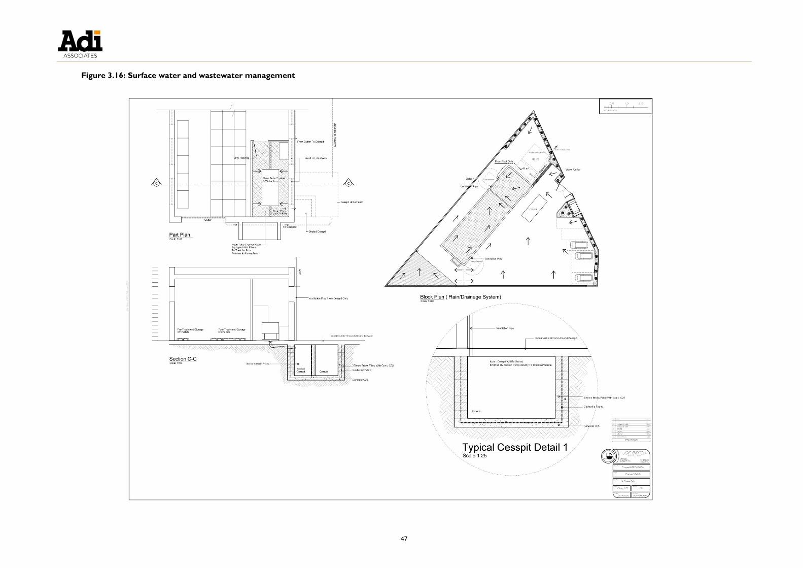
47
Figure 3.16: Surface water and wastewater management


49
EMPLOYMENT
3.86. During the excavation phase, it is expected that the Scheme will employ two to three
persons, increasing to five to six employees during construction.
3.87. It is envisaged that three persons will be employed once the Scheme comes into
operation, increasing to nine employees once the Scheme reaches full capacity.
ALTERNATIVES CONSIDERED
Alternative locations
3.88. The zero option alternative location to the Scheme site is the current site at Ta’
Maġġi Industrial Zone in Żabbar, which is already authorised to carry out WEEE
treatment under Environmental Permit number EP 009/10/F.
3.89. However, limitations at the current site are such that expansion and upgrading is not
possible. The Applicant intends to expand his operations to above the 50 tonne
storage threshold in the Industrial Emissions (Integrated Pollution Prevention and Control) Regulations, Legal Notice 10 of 2013, and to meet the requirements of this
legislation. However, installation of the proposed extensive air abatement and
wastewater management systems is not possible at the current site due to lack of
space.
3.90. The Applicant has been in discussion with MEPA over the relocation and expansion
of his activities for the past few years, and from time to time has informally proposed
to MEPA various alternative privately-owned sites that had become available for
purchase. However, MEPA has consistently guided the applicant to seek a location in
an industrial area. The Scheme site is the only site that has been made available to
the Applicant by the Malta Industrial Parks (MIP).
Alternative layouts and techniques
3.91. Various alternative layout options for the site were considered by the Applicant, and
a number of refinements in the layout and design have resulted in the current
Scheme.
3.92. The original design did not include details of the various designated areas in the
WEEE treatment building, including provisions for bunded storage, designated areas
for dismantling and treatment, and a quarantine area. Additionally, the storage of all
waste under cover in a shed, the installation of an impermeable membrane underlay
beneath the entire site, and vinyl flooring for the fluorescent tube crusher room
were not originally envisaged. The Scheme was amended to include these and other
elements following discussions on the potential environmental and operational
benefits.
3.93. In addition, the location of the main building on site has been shifted slightly
southeastward from the original design following advice from the Civil Protection
Department, to ensure that enough space is available for manoeuvring of fire trucks
on site in case of a fire. The rainwater reservoir was also originally envisaged as a

50
single reservoir, but the amended design shows it being split into two compartments
to ensure there is always at least 40 m3 available for firefighting if needed.
3.94. The cesspit for collecting wastewater from the fluorescent tube crushing room was
originally designed to collect wastewater from the entire building, and also included a
ventilation pipe. However, this was subsequently redesigned into two cesspits to
ensure appropriate segregation of the two wastewater streams, and the ventilation pipe was removed to create a sealed system and avoid any mercury vapour
emissions. A storage area for fluorescent tubes that are received broken was also
designated inside the fluorescent tube crushing room.
3.95. The post-dismantling storage area was also expanded to ensure sufficient space was
available for storage of dismantled items prior to delivery off-site.
3.96. Additionally, the after-hours skip was included on advice from MEPA to discourage
illegal waste disposal elsewhere.
3.97. The original proposal also included a mobile incinerator; however, this element is not
being considered further.
3.98. The Scheme site includes an area within the footprint that is earmarked for future
expansion.

51
4. LEGISLATION AND POLICY CONTEXT
INTRODUCTION
4.1. This chapter discusses the relevance of international and national legislation, and
Maltese planning policy, and the compatibility of the Scheme with this legislation /
policy. It highlights and assesses the policies of Government Ministries, where
relevant, and outlines those European Union (EU) Directives and Regulations, and
other international obligations, applicable to the Scheme.
4.2. As described, the legal basis for the Malta Environment and Planning Authority’s
(MEPA) request for the preparation of an Environmental Impact Assessment (EIA)
stems from the Environmental Impact Assessment Regulations published in 2007 (Legal
Notice 114 of 2007 as amended by Legal Notice 438 of 2011).
INTERNATIONAL LEGISLATION
4.3. International legislation relevant to the Scheme arises from International Treaties and
Conventions to which Malta is a signatory, EU legislation, and local legislation
transposing these.
The European Convention on the Protection of the Archaeological
Heritage (Revised)
4.4. This Convention, which was agreed in Valletta on 16th January 1992, amends the
original Convention (agreed in London in 1969) on the protection of archaeological
heritage. The aim of this (revised) Convention is “to protect the archaeological heritage
as a source of the European collective memory and as an instrument for historical and
scientific study”. This revision was brought about through the acknowledgement that
European archaeological heritage is under serious threat from deterioration as a
result of “major planning schemes, natural risks, clandestine and unscientific excavations,
and insufficient public awareness”. In the context of the Convention, archaeological
heritage includes “structures, constructions, groups of buildings, developed sites, moveable
objects, monuments of other kinds as well as their context, whether situated on land or
under water”.
4.5. The Convention requires the Contracting Parties to institute a legal system for the
protection of archaeological heritage, including:
The creation and maintenance of a heritage inventory;
The creation of archaeological reserves; and
Mandatory reporting to competent authorities of the chance discovery of
archaeological material.
4.6. The Convention also requires the Parties to apply procedures for the authorisation
and supervision of excavations and other archaeological activities to ensure that they
are undertaken by qualified persons and in a scientific manner.

52
4.7. Other provisions of the Convention include:
The physical protection of archaeological heritage;
Integrated conservation of the archaeological heritage (including through
reconciliation with development plans and other planning processes);
Resourcing rescue archaeology;
Collection and dissemination of scientific information;
Public awareness; and
Prevention of illicit circulation of elements of archaeological heritage.
4.8. Malta ratified this Convention on 24th November 1994 and it entered into force on
25th May 1995. The provisions of this Convention have been transposed into local
legislation by the Cultural Heritage Act of 2002 (see below).
Implications for the Scheme:
o Given the implications of the site in the context of its historical use, the
Superintendence of Cultural Heritage required an archaeological
investigation to be carried out prior to the final decision on the planning
application by MEPA. The Terms of Reference for the Archaeological
Investigation are presented in Appendix 2. For the purposes of the EIA,
MEPA did not require any detailed assessments.
EUROPEAN POLICY AND LEGISLATION
4.9. The Treaty establishing the European Community (Article 174) provides that
members should pursue the preservation, protection and improvement of the quality
of the environment, aim at a high level of environmental protection and apply policies
“….based on the precautionary principle and on the principles that Preventive action should
be taken, that environmental damage should as a priority be rectified at source”.8
8 Article 191 (ex Article 174 of the Treaty establishing the European Community):
1. Union policy on the environment shall contribute to pursuit of the following objectives:
- Preserving, protecting and improving the quality of the environment;
- Protecting human health;
- Prudent and rational utilisation of natural resources;
- Promoting measures at international level to deal with regional or worldwide environmental problems,
and in particular combating climate change.
2. Union policy on the environment shall aim at a high level of protection taking into account the diversity of
situations in the various regions of the Union. It shall be based on the precautionary principle and on the
principles that preventive action should be taken, that environmental damage should as a priority be
rectified at source and that the polluter should pay.
In this context, harmonisation measures answering environmental protection requirements shall include,

53
4.10. The relevant EU Directives include the EIA Directive 2011/92/EU on the assessment
of the effects of certain public and private projects on the environment, which has been
transposed by the Maltese Environmental Impact Assessment Regulations 2007, and
various Directives that relate largely to waste, water, and others as relevant. A
revised Environmental Impact Assessment (EIA) Directive (2014/52/EU) also entered
into force in 2014 and will start to be applied as from 16 May 2017.
4.11. Since the European Union’s environment acquis has been transposed into national
legislation, the Directives per se have not been assessed and instead the national
legislation transposing these Directives is assessed below.
NATIONAL LEGISLATION
The Constitution of Malta
Declaration of principles
4.12. The Constitution of Malta (Section 9) declares that the State shall safeguard the
landscape and the historical and artistic patrimony of the Nation. These are the only
aspects of the environment referred to in the Constitution, underlining the
importance of the landscape and historical heritage.
4.13. Local legislation relevant to the Scheme is described in the following sections.
Environment and Development Planning Act 2010 (Act X of 2010)
4.14. The Environment and Development Planning Act consolidates and updates the
provisions of the Development Planning Act 1992 (as amended) and the Environment
Protection Act 2001. Act X of 2010 provides for regulation and control in the
protection of the environment and in the planning and management of development.
4.15. The Act stipulates that “It shall be the duty of every person together with the Government
to protect the environment and to assist in the taking of preventive and remedial measures
to protect the environment and manage natural resources in a sustainable manner”.
4.16. Various duties fall to the Government. Those relevant to the Scheme are:
“4(a) to manage the environment in a sustainable manner by
integrating and giving due consideration to environmental concerns in
decisions on socioeconomic and other policies;
4(b) to take such preventive and remedial measures as may be
necessary to address and abate the problem of pollution and any other
form of environmental degradation in Malta and beyond, in accordance
with the polluter pays principle and the precautionary principle;
where appropriate, a safeguard clause allowing Member States to take provisional measures, for non-
economic environmental reasons, subject to a procedure of inspection by the Union.

54
4(e) to apply scientific and technical knowledge and resources in
determining matters that affect the environment;
4(f) to ensure the sustainable management of wastes and to promote
waste reduction and the proper use, reuse and recovery of matter and
energy;
4(g) to safeguard biological diversity;
4(h) to combat all forms of pollution;
4(i) to consider the environment as the common heritage and common
concern of humankind; and
4(j) to provide incentives leading to a higher level of environmental
protection”.
4.17. The Act makes provision for the establishment of an authority to implement the
duties of Government under the Act – the Malta Environment and Planning Authority
(MEPA). MEPA’s principal duties include:
the formulation and implementation of plans and policies relating to the
promotion of sustainable development, protection and management of the
environment, and the sustainable management of natural resources;
the promotion of proper planning and sustainable development, and the control
of development in accordance with the approved plans and policies;
advising the Minister responsible for the Environment on environmental
standards, guidelines and the making of regulations;
issuing licences or permits as may be required to control and manage activities
having an impact on the environment;
monitoring the quality of the environment, and establishing methodologies and
maintaining and disseminating information related to the environment; and,
ensuring that Environmental Audits and Environmental Assessments as may be
prescribed are properly carried out.
4.18. In determining an application for development permission, MEPA is required to have
regard to:
Development plans;
Planning policies;
Representations from the public; and

55
Any other material consideration the Authority deems relevant.
4.19. The Structure Plan and Local Plan Policies relevant to the Scheme are explained
below, and their implications on the Scheme are highlighted.
4.20. In making an application for development permission, an applicant must certify to MEPA that he is the owner of the site, or that he has notified the owner of his
intention to apply for development permission, and that the owner has granted his
consent to the development, or he is authorised to carry out the development under
any other law or through an agreement with the owner.
4.21. Act X also empowers MEPA to Schedule “areas, buildings, structures and remains of
geological, paleontological, cultural, archaeological, architectural, historical, antiquarian or
artistic or landscape importance as well as areas of natural beauty, ecological or scientific
value”.
Environmental Management Construction Site Regulations, 2007
4.22. The aim of the Environmental Management Construction Site Regulations is to limit
environmental degradation through construction management practices that cause
least nuisance to neighbours, minimise risk to workers, and safeguard private and
public property.
4.23. The Regulations apply to “...any construction, water mining, or any other disturbances to
the soil, including land clearing, scraping, ground excavation, land levelling, grading, cut and
fill operations, and ancillary activities that include travel to the construction site, travel on
access roads to and from the construction site and demolition activities”.
4.24. The Schedules within the Regulations provide requirements for reducing nuisance to
neighbours through:
Erection of a site notice containing details of the owner, site manager, architect
and contractor;
Conditions for cutting of stone and bricks on site;
Transportation of loose material;
Obstruction of pavements;
Hazards to vehicular traffic;
Cleaning of the site and its immediate vicinity;
Rodent control;
Hoardings around development sites;
Covered ways and barricades;

56
Safe passage past the site;
Nuisance abatement, including construction times; and
Control of dust emissions.
4.25. Technical guidelines and specifications are also provided for minimisation of noise and
vibration levels; health and hygiene, including waste management; hazardous materials
handling; and point source pollution from storm water.
4.26. The Regulations apply to any construction site, except where the Minister has
exempted such development under the provisions of Schedule VI ‘Exemptions’.
4.27. Regard has been given to the requirements of the Regulations in addressing the
construction impacts of the Scheme, including through the preparation of an outline
Construction Management Plan (CMP).
Legal Notices
4.28. The Regulations in force under the Environment and Development Planning Act 2010
include the following Legal Notices that are relevant to the Scheme:
Waste management and emissions
Legal Notice 106 of 2007: Waste Management (Activity Registration) Regulations
and Legal Notice 184 of 2011: The Waste Regulations (as amended by Legal
Notice 441 of 2011 and Legal Notice 384 of 2012). These Regulations
regulate the production and disposal of hazardous and non-hazardous wastes.
The Regulations aim to control all operations relating to the production and
management of waste and promote sound waste management practices so as to
safeguard human health and the environment.
Legal Notice 204 of 2014: Waste Management ( Electrical and Electronic Equipment) Regulations (as amended by Legal Notice 442 of 2012 and Legal
Notice 358 of 2013). These Regulations lay down measures to manage the
disposal of waste from electrical and electronic equipment (WEEE) with a view to
reducing any negative impacts and seeking to reuse and recycle thus improving
efficiency and being in line with the principles of sustainable development.
Schedule 5 of the Regulations sets Minimum Recovery Targets for each of the
categories over specific time periods.
Legal Notice 9 of 2013: Industrial Emissions (Framework) Regulations and Legal
Notice 10 of 2013: Industrial Emissions (Integrated Pollution Prevention and Control)
Regulations, 2013. These Regulations provide for integrated pollution prevention
and control of certain industrial activities and aim to ensure optimal
environmental performance by eliminating or reducing as far as possible emissions
to air, water and land and minimise waste generation.
Implications for the Scheme:
o The Scheme seeks to directly contribute to the scope of Legal Notice 204
57
of 2014 by providing a WEEE transfer and treatment facility that can
accept waste categories as listed within Schedule I of the Regulations. The
Scheme will reuse, recycle or recover 99% of incoming waste.
Waste management related to the construction of the Scheme and the
waste processing operations are discussed in Chapter 3 of the EIS. The
Construction Management Plan (CMP) that will be prepared for the Scheme will also address waste management issues. LN 10 of 2013 applies
to the Scheme, therefore, its operation, including emissions and waste
generation during operation will also be addressed through the Integrated
Pollution Prevention and Control environmental permit.
Water
Legal Notice 194 of 2004: Water Policy Framework Regulations (as amended by Legal Notice 24 of 2011 and Legal Notice 115 of 2012). These Regulations
are issued under both the Environment and Development Planning Act and the
Malta Resources Authority Act. They establish a framework for the protection of
coastal waters, inland surface waters, transitional waters, and groundwater. The
framework is intended to prevent further deterioration, and to protect, enhance,
and restore the status of aquatic systems.
Implications for the Scheme:
o The Scheme has been designed taking account of the need to ensure
against the contamination of water, as described in Chapter 3 of the EIS.
Noise
Legal Notice 193 of 2004: Assessment of Environment Noise Regulations sets the
scene for a survey and report on noise; it does not set levels or detail
measurement / assessment methodologies. Legal Notice 64 of 2002: Protection
of workers from the risks related to exposure to noise at work Regulations establishes
noise limits for outdoor machinery.
o These Legal Notices are not directly relevant to the Scheme, as they do
not provide guidance on the noise thresholds for residential areas and
guidance on how to measure it. For the assessment of noise impacts, UK
guidance and standards are used, as described in Chapter 8 of the EIS,
and as instructed by MEPA.
Other
Legal Notice 116 of 2005: Freedom of Access to Information on the Environment
Regulations (as amended by Legal Notice 298 of 2012). These Regulations
ensure freedom of access to and the dissemination of information held by public
authorities on the environment.
Implications for the Scheme:
o The EIS and its supporting documents fall under this Legal Notice and are

58
to be made public.
Malta Resources Authority Act 2001
4.29. The Malta Resources Authority Act established the Malta Resources Authority
(MRA) and assigns it a number of functions in relation to the regulation of the water,
minerals, and energy sector.
4.30. The Minister responsible for resources may, among others, also make regulations for
the granting, renewal, transfer, suspensions, and cancellation of licences, permits, or
other authorisations.
4.31. The regulations currently in force under the Malta Resources Authority Act that are
relevant to the Scheme include the Legal Notices listed hereunder:
Legal Notice 108 of 2009: The Protection of Groundwater against Pollution and Deterioration Regulations. These Regulations aim to protect groundwater against
pollution and deterioration.
Implications for the Scheme: o The Scheme has been designed taking account of the need to ensure
against the contamination of water, including groundwater, as described in
Chapter 3 of the EIS.
PLANNING POLICY
4.32. Planning policy relevant to the Scheme comprises policies embodied in the Structure
Plan for the Maltese Islands 1990, the South Malta Local Plan 2006, and Policy & Design
Guidance 2007.
Structure Plan for the Maltese Islands 1990
4.33. The following Structure Plan policies are relevant to the Scheme.
Built environment policies
4.34. POLICY BEN 1: Development will not normally be permitted if the proposal is likely to
have a deleterious impact on existing or planned adjacent uses because of visual intrusion,
noise, vibration, atmospheric pollution, unusually high traffic generation, unusual operating
times, or any other characteristic which in the opinion of the Planning Authority would
constitute bad neighbourliness.
4.35. POLICY BEN 2: Development will not normally be permitted if, in the opinion of the
Planning Authority, it is incompatible with the good urban design, natural heritage, and
environmental characteristics of existing or planned adjacent uses, and is unlikely to maintain
the good visual integrity of the area in which it is located.
Implications for the Scheme: o Issues related to visual impacts, traffic generation, and other issues of
general disturbance caused by the construction and operation of the
Scheme are addressed in detail in Chapters 3, 5, 6, 7 and 8 of the EIS.

59
4.36. POLICY BEN 12: The Planning Authority will decide if an Environmental Impact
Assessment of a form and content satisfactory to the Authority is required to accompany any
application for permission to develop. The environmental impact of proposed development
will be carefully assessed through development control procedures, and where development
permits are granted any adverse impacts will be mitigated through permit conditions and
any other necessary legal measures.
Implications for the Scheme:
o MEPA determined that the Scheme needs to undergo environmental
impact assessment. This EIS is a result of this process.
Settlement pattern and industry policies
4.37. POLICY SET 10: Major development will be undertaken at the following locations:
...4. Ħal Far and San Gwann as defined in Policy IND 1
4.38. POLICY IND 1: New Industrial estates, including warehousing, will be developed
northwest of the existing San Gwann industrial estate and east of the existing industrial
estate at Ħal Far. Development of the new Ħal Far area will be delayed until needs arise
which cannot be located elsewhere. Industrial estates will be zoned into smaller areas to
avoid incompatibility between adjacent uses, and to provide for the particular needs of
certain uses such as retail warehouses and large showrooms. Design guidelines will be
developed for the visual and functional aspects of industrial estates.
Implications for the Scheme:
o The Scheme site is the only site that has been made available to the
Applicant by the Malta Industrial Parks (MIP). The site is adjacent to
storage uses, a steel manufacturing facility, and concrete batching plants.
The Scheme includes measures for pollution prevention and control,
including air abatement, installation of a hardstanding surface with
impermeable underlay, as well as measures for surface water and
wastewater management. The operation of the Scheme will also be
regulated by an Integrated Pollution Prevention and Control (IPPC)
permit.
Public utility policies
4.39. POLICY PUT 14: Applications for the handling, treatment, and disposal of all waste,
excepting totally inert mineral wastes, will be considered only if an Environmental Impact
Assessment has been prepared for consideration by the Planning Authority. Permission will
only be granted when the responsible authorities are satisfied that the nature and control of
the operation will:
1. Protect natural resources against pollution
2. Protect the local environment against nuisance
3. Provide for an appropriate afteruse

60
Implications for the Scheme: o MEPA determined that the Scheme application requires an EIS following
the EIA screening process. The Scheme includes measures for pollution
prevention and control and for surface water and wastewater
management. Additionally, the operation and decommissioning of the
Scheme will also be regulated by an IPPC permit.
4.40. POLICY PUT 16: Sites will be identified at strategic locations in relation to the main
areas of population, commerce, and industry for the transfer or treatment of municipal,
commercial, and industrial inert/non toxic waste.
Implications for the Scheme:
o The Applicant was advised to consider the Scheme site by MIP.
South Malta Local Plan, 2006
4.41. The Scheme site is located within the Ħal Far Industrial Estate; the Estate is one of six
major employment concentrations identified in the Local Plan area. Figure 4.1
presents the Ħal-Far area policy map as presented in the Local Plan.
4.42. The Local Plan outlines a strategy for Ħal Far Industrial Estate that prioritises the
efficient use of the Estate:
The main strategic objectives of the Plan for Ħal Far are as follows:
i. Upgrading and promotion of Ħal Far as the major industrial
development area in Malta, whilst minimising its effects on
neighbouring zones and the surrounding environment;
ii. Establishing and protecting the recreational/sports area potential
through separate zoning;
iii. Maintaining the operation of industry compatible government
administrative functions;
iv. Improving the transport network and organising proper access points
to and circulation within the Estate; and
v. Protecting the environment in the vicinity of the Estate including the
scheduled NATURA 2000 coastal zone area and valleys to the
north/south and retaining an effective buffer from the rural
residential settlements to the west/east of the Estate.
4.43. This strategy is taken forward in the policy objectives outlined in POLICY SMHF01:
POLICY SMHF01- Industrial Development Boundary: The Industrial
Development Boundary for the Ħal Far Industrial Estate is being amended and
delineated as defined in the Ħal Far Policy Map HF 1 [refer to Figure 4.1]. Priority will be given to the efficient use of this industrial land for industrial uses only,
as designated on the Ħal Far Policy Map. MEPA will encourage the improvement

61
and upgrading of Ħal Far Industrial Estate. Industrial land uses in Ħal Far are to
ensure neighbourhood compatibility between individual industrial land uses. Any
industrial activity likely to cause problems to the nearby residential areas and
environment, as well as neighbouring units, by reason of noise, smell, vibration or
emissions, transport related impacts or because of the nature of the process carried
out, will not be permitted by MEPA, unless effective steps can be taken to control,
minimise and mitigate against any such adverse effects of the industrial activity.
Appropriate conditions will be imposed by MEPA on any development permissions
and environmental considerations will be accorded a high priority including the need
for an EIA and TIS, if required by MEPA.
Implications for the Scheme:
o The Scheme aims to provide a WEEE treatment facility that will contribute
to national WEEE collection and recovery targets. The Scheme includes
measures for the provision of air abatement, surface water management
and pollution prevention measures. The operation of the Scheme will also
be regulated by an IPPC permit.


63
Figure 4.1: Ħal Far Industrial Estate area policy map (South Malta Local Plan)


65
Development Control Policy and Design Guidance 2007
4.44. This policy document is relevant to the Scheme in terms of building design, building
height, access, parking requirements, and amenity. The Scheme takes account of the
provisions of this policy document.
Waste Management Plan for the Maltese Islands: A Resource
Management Approach (2014 – 2020), January 2014
4.45. This Plan aims to move the Maltese Islands’ current waste management practices up
the waste management hierarchy and sets a number of targets, as well as measures to
reach these targets.
4.46. The Waste Management Plan aims to promote the reuse, recycling and recovery of electrical equipment, to reach a 65% collection rate for WEEE by 2021, and to
achieve the following reuse, recycling and recovery targets by 2018.
Categories Re-use &
Recycling (%)
Recovery
(%)
1 and 10 (large households appliances and automatic dispensers) 80 85
3 and 4 (IT and telecommunications equipment and consumer
equipment)
70 80
2, 5, 6, 7 and 9 (small household appliances, lighting equipment,
electrical and electronic tools, toys, leisure and sports equipment,
monitoring and control instruments)
55 75
Gas discharge lamps 80 -
4.47. The above targets are consistent with those set by the Waste Management (Electrical
and Electronic Equipment) Regulations for the period 15th August 2015 to 14th August
2018. The Regulations will be extended to cover all electrical and electronic
equipment from 15th August 2018.
Implications for the Scheme:
o The primary objective of the Scheme is to provide a purpose-built facility
for the treatment of WEEE. The Scheme should contribute to the
achievement of the above national minimum WEEE collection and
recovery targets.
CONCLUSION
4.48. This chapter reviewed the legislation and planning policies relevant to the Scheme. It
has considered the relevant laws of Malta, Government Policies, and the policies of
the Structure Plan for the Maltese Islands, the relevant Local Plan, and subsidiary
planning documents, as well as EU legislation.


67
5. GEO-ENVIRONMENT
INTRODUCTION
5.1. This chapter describes the geology, geomorphology and hydrogeology within the
Scheme Site and its surroundings. It also includes an assessment of the impacts and
risks posed by the Scheme on the geo-environment.
5.2. The key geo-environment issues arising from the Scheme are outlined below:
Terms of Reference
5.3. The terms of reference (ToR) provided by MEPA are included in Technical
Appendix 1: Terms of Reference and Method Statements.
ASSESSMENT METHODOLOGY
5.4. The assessment methodology for the geo-environment study is described below.
The guidance on the protection of geology, geomorphology and hydrogeology is
outlined at the outset.
Standards and Policy Guidance
5.5. The principal sources of guidance for the impact assessment were the Structure Plan
for the Maltese Islands 1990, the South Malta Local Plan 2006, the Minerals Subject Plan
2002, and The Earth Conservation Strategy 1991 (The British Nature Conservancy
Council).
5.6. The European Union does not have any directive that protects the geo-environment
per se; however Directive 92/43/EEC (the Habitats Directive) seeks to preserve and
protect certain geological / geomorphologic features where these features constitute
important habitats. Important habitats include rocky coastlines and submerged caves.
This Directive has been transposed into national legislation (Legal Notice 311 of
2006).
5.7. Conservation profiles are intended to prevent future potential damage to sites. Since
no earth conservation model exists for the Maltese Islands, it has been suggested in
Key Issues:
Extraction of resources / features
Impact on ground water
Impact on surface water run-off

68
past studies (for example, Debono & Scerri, 19969 and Mallia et al., 199910) that until
such a model is formulated, models used in other countries can be adopted for local
use. The conservation model that has been used is that adopted by The Earth
Conservation Strategy of the Nature Conservancy Council (UK).
5.8. The relevant policies of the Structure Plan and the South Malta Local Plan are
described in detail in Chapter 4 of the EIS.
Area of Influence
5.9. The Area of Influence (AoI) for the geology and geomorphology study is shown in
Figure 5.1. The AoI for the hydrology and hydrogeology is shown in Figure 5.2.
5.10. In relation to establishing the quality of the material to be excavated, the area of
study was taken as the boundary of the Scheme Site. Figure 5.3 shows were core
samples were taken from.
9 Debono, G. and Scerri, S., 1996. North Harbours Local Plan Geology Survey Report. Prepared by Malta
University Services for the Planning Authority, Floriana, Malta; 72 pp. + 210 data cards + 15 figures + 20 plates. 10 Mallia, A., Briguglio, M., Ellul, A.E., and Formosa, S., 1999. Population, Tourism, Land-Use and Non-
Renewable Resources in the State of the Environment Report for Malta 1998, commissioned by the
Environment Protection Department, Government of Malta, Malta Council for Science and Technology, Malta.

69
Figure 5.3: Geology and geomorphology Area of Influence


71
Figure 5.2: Hydrology and hydrogeology Area of Influence


73
Figure 5.3: Location of boreholes


75
Geo-environment Methodology
5.11. The geo-environment study involved:
Identification and description of the geology, geomorphology and hydrogeology of
the site and the AoI;
Identification, mapping and description of any structural features, outcrop
formations, members, and bed sub-divisions, including their palaeontologic
content;
Identification and description of aquifers, water courses, drainage patterns;
surface run-off; and springs and wells (if any); and
Identification of features protected by legislation, or which warrant such
protection and their appropriate level of protection, as necessary.
5.12. The study resulted in the preparation of the following:
Geological Map;
Hydrology Map; and
Report of the quality of the stone material to be excavated and its potential
reuse.
BASELINE: GEOLOGY
Stratigraphy
5.13. The five late-tertiary formations exposed on the Maltese Islands are:
Upper Coralline Limestone (youngest);
Greensand;
Blue Clay;
Globigerina Limestone; and
Lower Coralline Limestone (oldest).
5.14. In addition to these formations, Quaternary continental deposits are also known to
occur sporadically on the Maltese Islands. An unconformity and an erosional surface
separate this unit from the underlying marine sedimentary succession.
5.15. The only rock formation preserved in the Study Area is the Lower Coralline
Limestone Formation.
5.16. Younger rock formations: Globigerina Limestone, Blue Clay Formation, Greensand
and Upper Coralline Limestone Formation, have been eroded away following
emergence of the Maltese Islands some five million years ago. No substantial

76
Quaternary deposits have been identified within the Study Area.
Lower Coralline Limestone Formation
5.17. As its name implies the Lower Coralline Limestone Formation is the lowermost rock
formation exposed on the Maltese Islands. It is extensively exposed in a cutting close
to the site, particularly on the slopes of Wied Żnuber and in the sheer cliff face the
lines the coastline.
5.18. This rock formation is of particular hydrogeological importance as its pores and
fissures host the mean sea level aquifer (MSLA) below the site.
5.19. The formation is known to be over 140m thick. Although the base of the formation
is taken at sea level, it extends lower down below sea level. The contact with the
overlying Globigerina Limestone Formation is sharp and is represented by a hard
ground. This is best seen outside the proposed site at il-Mara and Wied Moqbol.
5.20. The formation exhibits its maximum exposed thickness on the face of the sea-cliff
sections south of the site where the exposed section from sea level is about 60m
thick.
Subdivisions
5.21. The rock formation has been subdivided into four members as follows (Pedley, 1978):
Wied Magħlaq Member (oldest);
Attard Member;
Xlendi Member; and
Il-Mara Member (youngest).
5.22. Of the four members listed the Attard, and il-Mara members have been identified at
the Scheme site.
Attard Member 5.23. The contact with the overlying member is very conspicuous as the thick massive
white layers of this member pass to thinner brown and light brown calcarenite of the
Xlendi Member. The contact between the two units is sharp and is marked by a hard
ground. Four beds belonging to the Attard Member have been identified in Wied
Żnuber:
Detrital algal limestone bed with algal rhodoliths (at the base);
Algal rhodolith pavement bed;
Mollusc and coral bed; and
Recrystallised algal rhodolith bed.

77
5.24. Technical Appendix 2: Geo-environment Baseline Report describes each of these
five beds in further detail.
Xlendi Member 5.25. The unit is only 4m thick and appears to thin out considerably west of Wied Żnuber.
It is composed of moderately hard coarse to very coarse brown and light brown
apparently massive bedded calcarenites. It is characterised by the presence of
fragments of the echinoid Scutella.
Il-Mara Member
5.26. The il-Mara Member is about 15m thick and is best seen in cuttings close to the
Scheme site. At the top it is succeeded by foraminiferal mudstones and wackestones
of the Globigerina Limestone Formation. The contact with the overlying Lower
Globigerina Limestone was seen out of the site and was observed to be sharp.
Structural Geology
Faulting and regional dip
5.27. The strata are generally massive and their dip is generally in the same direction as the
regional dip of 30 to 60 to the NNE as can be seen in well exposed rock section in
Wied Żnuber and along the perimeter of the cutting south of the site. Two sets of
conjugate joints can be seen on the slopes of Wied Żnuber one set strikes northwest
– southeast while the other strikes approximately north-south. These joints are
near-vertical and have fracture frequency ranging from about 0.5m to 5m. Frequently
these have been opened by the chemical action of percolating water and
subsequently partly filled by terra rossa as can be noted in surface exposures.
5.28. No faults were seen in the AoI. The faults nearest to the site are found at Ta’ Wied
Fulija.
Bedding
5.29. In addition to the sub-vertical joints that dissect the site the limestone sequence
exposed in the Wied is bedded. On average beds are 0.8m up to 3m thick.
Stone material to be excavated
5.30. In order to assess the quality of the stone material two holes identified as BH1 and
BH2, were drilled on the site (see Figure 5.3) by continuous rock core sampling
using a rotary drill and a (76mm internal d iameter ) double tube core barrel with
water as the drilling fluid. Drilling logs are attached in Appendix 1 of Technical
Appendix 2: Geo-environment Baseline Report.
5.31. The rock core samples recovered from BH1 were of good quality Lower Globigerina
Limestone interbedded with beds of il-Mara member passing downward to massive
light brown rock of il-Mara member of the Lower Coralline Limestone formation.
Refer also to Technical Appendix 2: Geo-environment Baseline Report.
5.32. Only stiff red clay was recovered from BH2. No rock samples were recovered.

78
This could be either because drilling took place in a vertical fissure filled with clay or
else a larger solution cavity also filled with stiff red clay. Fracture planes were stained
with brown clay.
5.33. The laboratory test results (presented in Technical Appendix 2: Geo-
environment Baseline Report) revealed that the rock to be excavated is composed
of yellow bioturbated Lower Globigerina Limestone interbeds passing down to il-Mara member with an average compressive strength of 13.9MPa. Water content was
noted to be relatively very high.
5.34. Due to the relatively low compressive strength and the high water content the lower
beds are suitable for mass concrete such as C12. If the red clay in BH2 occur s in
relatively large quantities this could be used as soil for embellishing the site and for
other agricultural use elsewhere. The quantity of red clay present can only be
determined upon further investigation or by inspection during the construction
phase.
BASELINE: GEOMORPHOLOGY
5.35. The environs of the site with the exception of the Wied Żnuber and Wied il-Mixta
valleys and the cliff line are highly disturbed on account of successive developments
first as an ex-services airport and then during the construction of the present Ħal Far
Industrial Estate. For this reason the geomorphology of the A of I is primarily
controlled by the regional dip to the northeast giving rise to sheer cliffs and NNE
jointing on which the valley of Wied Żnuber appears to be superimposed.
5.36. Contrasting lithological composition of the rock members and bed units gave rise to
the present profile of slopes of the valley also characterised by intense karstification.
5.37. The geomorphological units that make up the A of I are:
The high cliff coastline;
The Ħal Far plain;
Wied Żnuber;
Wied il-Mixta; and
Karst features.
Cliff coastline
5.38. The most impressive geomorphologic feature close to the site is the imposing sheer
limestone cliffs that rise almost vertically to about 60m above sea level. Their origin is
closely related to the gentle dip of the Maltese Islands to the northeast and wave
action at the toe of the cliff face, which undermines the rock face. The rock face fails
along vertical shear planes giving rise to the sheer cliff. On account of the regional
dip, run-off over the cliffs is scarce. Erosion is mainly by the action of gravity.

79
Ħal Far plain
5.39. This unit forms the disused airfield and appears to represent the bedding plane at the
top of Il- Mara Member which is marked by a hard ground. This bedding plane is
particularly resistant to weathering in contrast to the overlying beds of the
Globigerina Limestone Formation, which have been eroded to expose the top of the
Lower Coralline Limestone, Il-Mara Member. The Ħal Far plain is therefore
considered to be the surface expression of a bedding plane.
5.40. Two valleys run through this plain, namely Wied Żnuber and Wied il-Mixta.
5.41. Wied Żnuber is a deep gorge incised down to a maximum depth of about 60m in
Lower Coralline Limestone. It is one of the few drainage systems that discharge on
the south west coastline. These dry watercourses are characterised by a relatively
small catchment and are deeply incised in Lower Coralline Limestone. It discharges
at sea level.
5.42. Like Wied Żnuber, Wied il-Mixta is a dry watercourse deeply incised in Lower Coralline Limestone. It has a relatively small catchment and drains the eastern end of
the Ħal Far Industrial Estate. Unlike Wied Żnuber, it is a hanging valley as it does not
discharge its run-off at sea level.
5.43. Karst features are also noted on the plain and are the product of the action of
rainwater on limestone. Rocks of the il-Mara, Xlendi, Attard and Wied Magħlaq Members are prone to solution producing a variety of solution features, which highly
enhance the permeability of limestone. These range from shallow rock pools and
narrow conduits to large solution features such as caverns. One such cavern now
modified by anthropogenic activities can be seen on the western slopes of the valley.
A much larger solution cavern is Ħasan’s cave that can be seen perched in the cliff face some 500m southeast of the site. Rock pools, conduits and open joints are best
seen on the limestone pavement that lines the flanks of the Wied Żnuber gorge. The
Lower Coralline Limestone is composed of a pure limestone and for this reason
residual clays in the form of terra rossa soil are scarce. The limestone is therefore
bare and is exposed as a limestone pavement locally known as ‘Xagħra’.
5.44. Rock permeability is further enhanced by the widening of fractures and bedding
planes by chemical solution. Fractures frequently channel percolating rainwater, and
in the process widen the open fracture by the solution.
Soil
5.45. The soil in the study area is dominated by terra rossa –Xagħra series and L-Inglin Complex (refer also to Technical Appendix 2: Geo-environment Baseline
Report). This is found mostly within Wied Żnuber and along the cliff line. At the site
and the entire Ħal Far Industrial Estate the soil has been mostly disturbed. Such
disturbance at times almost reaches the cliffs.


81
Figure 5.4: Geological map of the Area of Influence (OED, 1993)


83
BASELINE: HYDROGEOLOGY
5.46. The hydrological / hydrogeological features close to the site are:
The mean sea level aquifer;
Ephemeral Watercourse of Wied Żnuber;
Catchment of Wied Żnuber;
Catchment of Wied il-Mixta; and
Water Boreholes – Water Services Corporation.
Mean Sea Level Aquifer
5.47. There is no perched aquifer beneath the site as there is no impermeable rock layer
such as the Blue Clay Formation, in the rock sequence beneath the site. As there is
no other impermeable rock formation present in the lithologic succession the only
aquifer beneath the site is the mean sea level aquifer, which lies some 60m below.
This also represents the hydrogeological feature closest to the site.
5.48. The sea level aquifer is lens shaped reaching some 3.5m high above sea level at the
centre of the island and thins out to zero thickness at the coastline. As the site is
only about 800m away from the coastline, the aquifer is either very thinly developed
or not at all.
Wied Żnuber watercourse
5.49. The watercourses of these valley systems have their origin at the Ħal Far Industrial
Estate, flowing through the old runway and Wied Żnuber and discharging to the sea.
A true watercourse is only developed in Wied Żnuber. Presently this is considered
to be a relict geomorphological feature generated in past climates during the
Pleistocene. No water flows through the valley system except run-off water
generated during heavy downpours. This run-off ceases soon after the rain has
stopped. This watercourse discharges at sea level.
Wied il-Mixta and site catchments
5.50. The site lies within the catchment of Wied Il Mixta, which is a hanging valley in
contrast to Wied Żnuber. The watersheds of Wied il-Mixta and the site are shown in
Figure 5.5. The area of the catchment of the Wied is of modest size, 1.78 km2, while
that of the site is very small at 0.07 km2.
5.51. As was observed during the field survey, the rock mass has high fissure permeability.
The frequency of fissures observed on site can be as close as 1m and even less.
Water boreholes
5.52. The nearest public borehole (Water Services Corporation) tapping the mean sea
level aquifer lies at Ħal Far some 1,000m away from the site. It lies outside the area
of influence of the site. A number of private boreholes are also present in the

84
vicinity.
Surface run-off estimates
5.53. In order to calculate the surface run-off resulting from annual precipitation,
watersheds were drawn for the discharge point of Wied il-Mixta and the Scheme site
(see Figure 5.5). The result of the run-off calculations are listed below:
Wied il-Mixta - Wied Catchment – 424,000 m2;
Scheme site catchment -1,600 m2;
Average rainfall for the Maltese Islands - 550mm;
Average Percolation - 24%;
Average Evapo-transpiration - 70%;
Average run-off at Wied il-Mixta discharge point - 6% or 14,000 m3 of water; and
Average run-off at Scheme site discharge point - 6% or 50 m2 of run-off water.

85
Figure 5.5: Hydrology and hydrogeology


87
ASSESSMENT OF IMPACTS
Impact significance
5.54. The following criteria were used to assess the significance of the impacts by the
Scheme on the geology, geomorphology and hydrogeology within the respective AoI:
Not significant:
o Little or no change to the geological, geomorphological and
hydrogeological regime.
Minor significance:
o Changes to the geological, geomorphological and hydrogeological regime
that may affect neighbouring properties but which may be offset by
mitigation measures.
Major significance:
o Changes to the geological, geomorphological and hydrogeological regime
that may affect neighbouring properties and which may not be offset by
mitigation measures (if negative) or may be enhanced by mitigation
measures (if positive).
Prediction and significance of impacts
Extraction of resources / features
5.55. The predicted impact of the Scheme on the underlying geology and the
geomorphology of the AoI is considered to be of minor to major significance, since it
involves the extraction of mineral resources, however,. it is envisaged that only
approximately 1,130 m3 of material will be excavated from the Scheme Site.
Impact on groundwater
5.56. Potential impacts on the groundwater could result from spillages of oil/fuel and
leakages from batteries. Given the small quantities to be stored on site and the
distance to the water table it is likely that, with mitigation in place, the potential
impact is minor, and major only in cases of a large spillage.
5.57. In terms of mitigation, given that the Scheme will include an impermeable
hardstanding and oil-water interceptor, and with specific bunding in place for oily
waste, the predicted impact of the Scheme on ground water is considered to be not
significant given the low risk identified in the risk assessment of spillages able to reach
the water table.
5.58. Potential impacts on ground water due to mercury deposition off-site are unknown
(refer to Chapter 9).

88
Impact on surface water run-off
5.59. In the case of a fire, the potential impact from used firefighting water is likely to be
minor because of the mitigation that is in place: used water will be collected in the
cesspit / reservoir and any overflow leaving the site will have been treated. The
likelihood of a fire is considered rare, due to the operational procedures that will be
in place to limit the quantity of flammable waste stored and risk of fire, see also
Chapter 9.
MITIGATION
5.60. Mitigation measures during operation include:
The entire site surface will be covered in concrete underlain by a geotextile
membrane;
The ground in outdoor areas of the site will be laid to fall towards an oil-water
interceptor before being received in the reservoir;
Wastewater from any washing of floors in the WEEE treatment building will be collected in gutters, filtered to remove trace contaminants, and received in an
underground cesspit for reuse;
Only treated surface water / wastewater will be received in the underground
reservoir and cesspits; and
Cesspits will be impermeable.
RESIDUAL IMPACTS
5.61. Residual impacts will remain as not significant in the case of the impact on ground
water and minor in the case of potential overflow of used fire water on surface water
run-off. In the case of the impact on mineral resources, the residual impact remains
minor to major since the impact cannot be mitigated.

89
Table 5.1: Summary of Impacts on the Geo-environmental Resources
Predicted
impact
Beneficial
/
adverse
Nature, scale and type of impact Policy
Importance
Probability
of impact
occurring
Significance
of Impact Proposed
mitigation
measures
Significance
of residual
impact
Excav’n/
Constr’n/
Oper’n
Extent of
impact
(nat/local
/site)
Direct/
indirect
S’term/
l’term
Perm/
temp
Revers/
Irrevers
(Inter/
national/
local)
(Likely/
unlikely/
remote/
uncertain)
(Major /
minor / not
significant)
(Major/
minor / not
significant)
Mineral
resources /
features
Adverse Constr’n Local Direct Long-
term Perm Irrevers Local Likely
Major
significance
Use of
excavated
material in
cement
manufacture
and use of clay
in landscaping
and/or for
agriculture
Major
significance
Change in
quality of
ground water
Adverse Constr’n /
Oper’n Local Indirect
Short-
term /
Long-
term
Perm Irrevers Local Likely Minor to
major
Entire site lies
on an
impermeable
surface, specific
bunding to
capture specific
oil spillages, oil-
water
interceptors,
impermeable
cesspits
Not
significant
Contamination
of surface water
runoff
Adverse Constr’n Local Direct Long-
term
Perm Irrevers Local Likely Minor to
major in case
of overflow
of used
firewater,
depending on
Used firewater
passing through
interceptor
Minor
significance in
case of
overflow of
used
firewater,

90
extent of
overflow
otherwise
not significant
otherwise,
not significant

91
6. LANDSCAPE AND VISUAL AMENITY
INTRODUCTION
6.1. This chapter addresses the potential impacts of the Scheme on landscape and visual
amenity. It describes the existing landscape and visual amenity of the Application Site
and its surroundings, and assesses how this might change through the development of
the Scheme.
6.2. Assessment of landscape and visual amenity involves examination of the wide range of
factors that contribute to the qualities and attributes of the existing landscape and
that may contribute to the landscape of the Scheme. This involves consideration of
the evolution of the landscape and the factors that have led to its current condition,
from the underlying geology through to anthropogenic activities.
6.3. Landscape and visual impacts are distinct, albeit strongly related. Landscape impacts
result from the interaction between a development and the existing landscape
resources, experienced through changes to any element or combination of landscape
elements. Visual impacts relate to the effect that a development would have on the
amenity of sensitive receptors (those experiencing views of the site), relating to the
actual or perceived visible changes to the character and quality of the landscape.
6.4. The key issues for the assessment are:
Key Issues:
Effects on the landscape setting of the Scheme
Changes in views of key receptors
Terms of Reference
6.5. The Terms of Reference (ToR) issued by MEPA require that the landscape and visual
amenity aspects and potential impacts on these aspects are assessed. The full ToR
are presented in Technical Appendix 1: Terms of Reference and Method
Statements.
Objectives of the Assessment
6.6. The objectives of the landscape and visual amenity study were to:
Undertake a baseline survey and characterisation of the landscape and visual
amenity at and around the Application Site, using desk top and field survey
techniques;

92
Evaluate the landscape character of the Application site and its setting;
Establish the Zone of Theoretical Visibility (ZTV)11 for the Scheme and identify
the key viewpoints and receptors;
Input the potentially beneficial design measures to the Scheme;
Predict the impacts of the Scheme on the visual amenity in the ZTV;
Assess the significance of the impacts on the landscape and visual amenity of the
ZTV; and
Describe the mitigation measures designed into the Scheme to minimise adverse
impacts and enhance any beneficial impacts on the landscape and visual amenity.
Legislation and Policies Guidance
6.7. The Constitution of Malta (Section 9) declares that the State shall safeguard the
landscape and the historical and artistic patrimony of the Nation. These are the only aspects of the environment referred to in the Constitution, underlining the
importance of the landscape and historical heritage.
Structure Plan
6.8. The Structure Plan for the Maltese Islands identifies a number of policies that are
relevant to assessing landscape and visual amenity and the impact of projects thereon.
Policy BEN 1 deals with bad neighbourliness, and specifically with the visual intrusion
of projects. Policy BEN 2 provides that development will not be permitted if it is
unlikely to ‘maintain the good visual integrity of the area in which it is located’ (refer also
to Chapter 4).
South Malta Local Plan
6.9. The South Malta Local Plan (SMLP) 2006 is relevant to the Scheme. The Scheme site
is located within the Ħal Far Industrial Estate, specifically designated for industrial
uses. There are no designations related to landscape at this site.
Landscape Assessment Study of the Maltese Islands
6.10. MEPA’s Landscape Assessment Study of the Maltese Islands was undertaken in 2004
as part of the Structure Plan Review. The Study does not provide an assessment
methodology to use in order to consider the impacts of a specific development; it
does, however, provide a useful baseline assessment of the prevailing landscape
character of the Maltese Islands. The primary purpose of the Study appears to have
11 In accordance with the Guidelines for Landscape and Visual Impact Assessment (Third Edition) (2013), the
term Zone of Theoretical Visibility (ZTV) is being used in place of the term Zone of Visual Influence (ZVI) since
it makes clear that the area thus defined shows land from which the proposal may theoretically be visible and
does not take account of potential screening by vegetation and buildings.

93
been as a topic paper to identify Areas of High Landscape Sensitivity and inform the
Structure Plan Review.
6.11. The Study identifies the Application Site as lying within the Kalafrana-Ħal Far
Landscape Character Area. The Ħal Far industrial estate occupies the western part
of this Landscape Character Area. It was developed on an ex-military airfield. The
area between Ħal Far and Kalafrana consists of farmland and includes a hamlet and a
number of farms.
Standards and guidelines
6.12. In view of the fact that there are no Malta-specific landscape and visual amenity
assessment guidelines, MEPA requested that the landscape and visual assessment be
carried out in line with the UK’s Guidelines for Landscape and Visual Impact Assessment
2013 (GLVIA) (Institute of Environmental Management & Assessment (IEMA) and the
Landscape Institute).
ASSESSMENT METHODOLOGY
Desk study methodology
Landscape assessment
6.13. The landscape baseline conditions were determined through desk study and field
surveys. The desk study included:
A review of the information shown on the base map of the area and reference to
the maps prepared for the geo-environment and land use aspects of the EIS;
An analysis of aerial photographs to determine land use trends; and
A review of existing baseline information from:
o Literature searches;
o Previous environmental and planning studies undertaken in the area;
o Historic maps; and
o Legislation and policy documents.
Landscape character, value and sensitivity 6.14. MEPA’s Landscape Assessment Study of the Maltese Islands was carried out as part of
the Structure Plan review. This study characterised the landscape at a national level
into a series of units known as landscape character areas (LCAs). It describes
landscape characteristics, qualities and influences on the landscape. The landscape
character area of the site and its surroundings consider MEPA’s landscape assessment
study as well as the results of the desk and field studies when characterising the
landscape in the area.
6.15. The value of the landscape receptor should also be considered. The value of a
landscape character receptor is a reflection of its importance in terms of any
designations that may apply, or its importance in itself as a landscape or townscape

94
resource, which may be due to its ecological, cultural or recreational value. The
higher the value of the receptor, the greater is its sensitivity to the development.
Value is assessed as being high, medium, or low.
6.16. Landscape sensitivity is a complex issue. The GLVIA refer to consideration of a
landscape’s susceptibility to change, meaning ‘...the ability of the landscape receptor...to
accommodate the proposed development without undue consequences for the maintenance of the baseline situation and/or the achievement of landscape planning policies and
strategies.’ Landscape character sensitivity was defined in accordance with the criteria
set out in Table 6.1.
Table 6.1: Landscape character sensitivity
Landscape Character Sensitivity (directly affected areas)
High Medium Low
A landscape character area /
local landscape tract in which
defining characteristics are
susceptible to change
A landscape character area /
local landscape tract in which
some defining characteristics
may be susceptible to change
A landscape character area /
local landscape tract in which
defining characteristics are less
susceptible to change
Landscape Character Sensitivity (indirectly affected areas)
High Medium Low
A landscape character area /
local landscape tract in which
defining characteristics are
susceptible to change
A landscape character area /
local landscape tract in which
some defining characteristics
may be susceptible to change
A landscape character area /
local landscape tract in which
defining characteristics are less
susceptible to change
Magnitude of change to landscape resource
6.17. The GLVIA describe that the identification of the magnitude of change depends on (i)
the size or scale of change in the landscape that is likely to be experienced as a result
of each effect; (ii) geographical extent over which the landscape effects will be felt;
and (iii) the duration and reversibility of the landscape effects. The magnitude of
change in a landscape depends on the loss, change or addition of any feature, or any
change in the backdrop to, or outlook from, a landscape that affects its character.
Table 6.2 presents criteria for magnitude of change to a landscape resource.

95
Table 6.2: Magnitude of change to landscape resource
High Medium Low Imperceptible
change
An obvious change in
landscape
characteristics and
character
Discernible changes to
landscape
characteristics and
character
Small changes to
landscape
characteristics and
character
A largely imperceptible
change to landscape
characteristics and
character
Visual amenity assessment
6.18. The Zone of Theoretical Visibility (ZTV) was defined using a combination of desk and
field-based techniques. The extent of the viewshed (ZTV) was verified in the field
along with the eleven representative viewpoints that were agreed with MEPA for the
visual amenity assessment (see below). The existing views from these locations were photographed, photomontages created, and the visual amenity and changes thereto
as a result of the Scheme appraised.
6.19. MEPA’s agreement to the location of the viewpoints was sought before the visual
amenity study was undertaken. The viewpoints include:
Short distance views;
Medium distance views from publicly accessible locations; and
Long distance views from high points or tourist attractions.
6.20. A number of views from publicly accessible locations were identified within the ZTV
as shown in Figure 6.1. These were agreed with MEPA as a basis for assessing
changes to visual amenity that may result from the Scheme. However, due to the lie
of the land and the relatively low Scheme height, during the preparation of
photomontages it was identified that the Scheme would only be visible from
viewpoint 4. The assessment, therefore, considers potential visual impact at this
viewpoint.
Sensitivity of visual receptors 6.21. The sensitivity of visual receptors is dependent on the location from where the
receptors experience the view, their expectations, occupation or activity at the
viewpoint, and the importance of the view. UK Guidelines note that the most
sensitive receptors may include:
Users of outdoor recreation facilities whose attention or interest may be focused
on the landscape;
Communities where the development results in changes to the landscape setting
or valued views enjoyed by the community;
Visitors to heritage assets, or to other attractions, where views of the
surroundings are an important contributor to the experience; and

96
Occupiers of residential properties with views affected by the development.
6.22. The Guidelines also note that other receptors could include people engaged in
outdoor sport or recreation other than those involving an appreciation of the
landscape, people travelling through the area, and people at their place of work. The
latter are regarded as the least susceptible to changes in view.
6.23. The following definitions are used to categorise the sensitivity of receptors:
High sensitivity receptors: those who repeatedly re-visit the viewpoint to partake
of the view. Such views are generally highly valued by the community;
Moderate sensitivity receptors: itinerant visitors (mostly tourists) to the
viewpoint; and
Low sensitivity receptors: road users, workers, etc.
6.24. Residents are not included above because views from private property are not
protected under planning law or other public policy, except in so far as the zoning of
the land implies certainty as to the type of development that may be permitted. The
rights of nearby residents are, however, somewhat protected through the planning
system, since they can object to any change of land use (or airspace). The EIA
process does not assess the impacts of a development on the rights or values of
individuals, but rather on the public collectively, and those rights and values are as
expressed in legislation and planning policy. It is for this reason that this EIS does not
address the effects of loss of view from private properties, land ownership, etc.
Magnitude of visual change
6.25. Identification of the magnitude of change depends on the size or scale in change in
view (relating to the extent of visibility, degree of screening, angle of view and
distance from the development) and the degree of contrast or integration of any new
features with existing features as well as the duration and reversibility of visual
effects. Table 6.3 defines magnitude of visual change.
Table 6.3: Magnitude of visual change
High Medium Low Imperceptible
Change
A substantial change in
view affecting a large
number of viewers
A moderate change in
view affecting
many/some viewers
A smaller change in
view affecting a low
number of viewers
A small, barely
perceptible or no
change in view.
Field survey methodology: landscape
6.26. A comprehensive field survey was undertaken in April 2015, in accordance with the
Guidelines for Landscape and Visual Impact Assessment (IEMA and the Landscape
Institute 2013). The field survey served to record objective and subjective
impressions of the landscape, and details of landscape condition, land use, and

97
management. It provided the basis for the delineation of local landscape tracts and
the identification of potentially sensitive landscape receptors in accordance with the
Guidelines.
6.27. Table 6.4 describes the identified landscape receptors.
Table 6.4 Landscape Receptors
Landscape elements
Industrial estate: Characterised by large factories. The estate was
developed on a former airfield and related infrastructure, such as the
runway, taxi way and aircraft parking areas still remain. Some is used
for the drag racing strip, other parts for a go kart club and model
aeroplanes, and large areas as abandoned pavement – now used as an
undefined road forming one of the two principal access routes to the
estate.
Urban settlement: The coastal town of Birżebbuġa, includes a reclaimed
beach along the coastline.
Rural area: Occupying the area between the industrial estate and the
port and settlement. Typical rural landscape including rubble walls,
fields as well as trees. Eucalyptus trees also dot the rural area.
Port: Includes the Freeport and oil and gas storage facilities. The tall
cranes at the Freeport are distinctive in this landscape.
Cliffs: The southern coastal cliffs are a distinctive natural landscape
feature, and are also important from an ecological view in their role in
seabird ecology. Wied Żnuber is also a noticeable feature; a deeply
incised valley that extends from the sea to the top of the Lower
Coralline Limestone member. The area is scheduled as Area of
Ecological Importance, Site of Scientific Importance and a Natura 2000
site.
Landscape characteristics
The Ħal Far Industrial Estate is the largest one in Malta. The estate is
spacious and includes a number of, as yet, undeveloped sites. It is
currently occupied by a wide range of industrial uses ranging from
motor vehicle repairs and transport companies to paint manufacture,
pharmaceuticals and plastics and rubber processing units.
The urban conurbation of Birżebbuġa is largely a tourism related and
residential area. There are a number of food and beverage
establishments along the coast. The Birżebbuġa sailing club is also
located on the coast, relatively close to the Freeport.
The rural area slopes down towards the sea. It is sandwiched between
the industrial estate, the Freeport and urban settlement, such that the
area lacks a feeling of remoteness in the vicinity of these landscapes.
The Malta Freeport and oil and gas storage operate within a scenic bay.
The Freeport is dominant in the landscape both visually and in terms of
the noise and light it generates such that its maritime commercial
activity is omnipresent in the bay.
The cliffs provide a sense of remoteness and wilderness in the vicinity
of the rural area. In the vicinity of the industrial estate, there is
relatively extensive tipping and dumping. This together with the noise
and light from the industrial estate (in the evening) has resulted in
dilapidation of the natural habitat and environment.
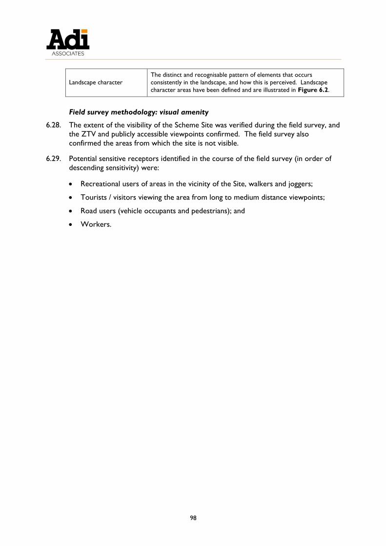
98
Landscape character
The distinct and recognisable pattern of elements that occurs
consistently in the landscape, and how this is perceived. Landscape
character areas have been defined and are illustrated in Figure 6.2.
Field survey methodology: visual amenity
6.28. The extent of the visibility of the Scheme Site was verified during the field survey, and
the ZTV and publicly accessible viewpoints confirmed. The field survey also
confirmed the areas from which the site is not visible.
6.29. Potential sensitive receptors identified in the course of the field survey (in order of
descending sensitivity) were:
Recreational users of areas in the vicinity of the Site, walkers and joggers;
Tourists / visitors viewing the area from long to medium distance viewpoints;
Road users (vehicle occupants and pedestrians); and
Workers.

99
Figure 6.1: Zone of Visual Influence and selected viewpoints

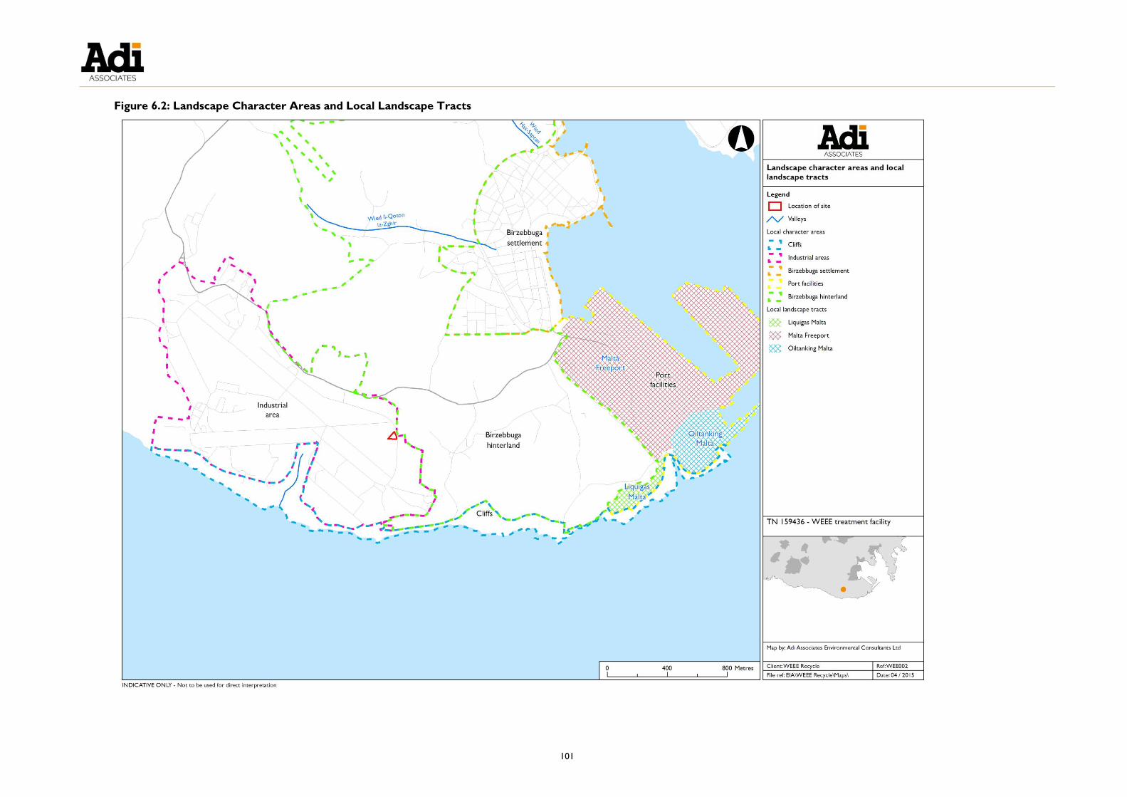
101
Figure 6.2: Landscape Character Areas and Local Landscape Tracts


103
DETERMINING IMPACT SIGNIFICANCE
6.30. The significance of impacts on the landscape and visual amenity is dependent upon
judgements about the value of the existing visual amenity compared to the new visual
amenity that would be created, the number of people affected, the receptors’
sensitivity to change, the magnitude, duration and permanency of the changes, and subjective judgements about the degree to which these changes would matter to
those concerned
Landscape assessment
6.31. The significance of landscape impacts has been defined based on the sensitivity and
magnitude criteria as described in Table 6.1 and Table 6.2, as follows:
Major significance: Large negative changes in the landscape that are out of character with the landscape. Where the extent of the negative impact on the
landscape setting is large in scale or magnitude and the landscape sensitive
receptor is of high sensitivity to change and / or of a high intrinsic value and, as a
consequence, the integrity of the setting would be significantly altered. The
impact would be of international or national importance. The impact would be of
a long-term nature (or very severe short-term in the case of construction
impacts), irreversible, and certain or likely to occur;
Moderate significance: Discernible changes in the landscape that are out of
character with the landscape. Where the extent of the negative impact on the
landscape character is medium in scale and landscape sensitive receptor is of
medium sensitivity to change and/or of medium intrinsic value. The impact
would be of a long-term nature, irreversible and likely to occur;
Minor significance: Small changes in the landscape that are out of character with
the landscape. Where the extent of the negative impact on the landscape setting is small in scale or magnitude and the landscape sensitive receptor is of a low
sensitivity to change or a low intrinsic value. The impact would be of local
importance. The impact would be of a long or short-term nature, and likely to
occur;
Not significant: No perceptible changes to the landscape setting. Where the extent of the negative impact on the landscape setting is of limited importance in
scale or magnitude and the landscape sensitive receptor is of a low sensitivity to
change and / or a low intrinsic value. The impact would be of local importance.
The impact would be of a long to short-term nature, and / or unlikely to occur.
Visual amenity
6.32. The significance of visual impacts has been assessed in relation to:
The number and sensitivity of receptors affected;
The duration of the changes;

104
The extent of visibility and distance from the Scheme;
The type of view – proportion of development visible, focus on Scheme due to
proximity and whether it is fixed, transient, or sequential;
The changes to the view from the identified view points as shown by the
photomontages; and
The scope for mitigation / enhancement measures to screen the development.
6.33. Based on the above criteria an assessment of the significance of the visual impact on
each of the agreed viewpoints was made in terms of whether it is considered to be
of:
Major significance - substantial changes in the view. Where the extent of the
impact on the view would be large in magnitude and affect a large number of
receptors or is of particular importance to the viewers affected. May be an
advertised viewpoint and/or a view with high amenity and scenic qualities and
few intrusive elements in the view;
Moderate significance – moderate change to the view. Where the extent of the impact on the view would be moderate in magnitude or extent and affect a
moderate number of receptors or is of some importance to the viewers affected.
May be a viewpoint from which there is a view with some visual amenity /
intrinsic value (this may include views across, or within, a regionally or locally
designated landscape) and potentially some intrusive elements to the view;
Minor significance – smaller changes to the view. Where the extent of the
impact on the view would be small in magnitude or extent, and affect relatively
few receptors, or a larger number of receptors with passing interest in their visual environment. The view would have a low visual amenity / intrinsic value or
with intrusive man-made elements within the view. ; or be
Not significant - little or no obvious changes to the view. Where the extent of the
impact on the visual amenity would be of limited importance in scale or
magnitude, or affect persons of low sensitivity to change, and / or be a view of
low intrinsic value. Alternatively, the impact would affect very few people, be
transient and only affect a small part of the Scheme or panorama.
6.34. Table 6.5 identifies impact significance in a tabular format. It should be noted that
there is a gradual transition between categories and magnitude and sensitivity are not
necessarily evenly weighted such that the final decision on significance comes down
to a professional judgement. Impact significance is recorded as one of the four
categories (not significant, minor, moderate, or major).

105
Table 6.5 Identification of Impact Significance
Magnitude of change
Imperceptible Low Medium High
Sensitivity of
Receptor
Low Not significant Not significant
or Minor
Minor Minor or
moderate
Medium Not significant Minor Moderate Moderate or
major
High Not significant Minor or
moderate
Moderate or
major
Major
EXISTING CONDITIONS
Landscape
6.35. The Application Site is located within the Ħal Far Industrial Estate. The Industrial
estate is situated on a former airfield, lying on the coast between Żurrieq and
Birżebbuġa. Given its relatively large size, the industrial estate provides a sense of spaciousness, in contrast to the generally dense conurbations throughout Malta,
although it has not yet been developed to maximum capacity. Other uses have been
developed in its vicinity including warehousing and the setting up of a detention
centre.
6.36. The Application Site is flanked by an existing operation that includes a container
depot. It also abuts, as yet, undeveloped land that mainly appears to consist of
material that has been dumped on to a former taxi way and is now overgrown with
vegetation. Concrete batching plants are located over the road from the Application
Site and the adjacent area is used as a shooting range. The shooting range does not
appear well maintained although it is still used on the weekend. Beyond this area, the
land begins to slope eastwards. It is dominated by rural land that includes areas of
planted Eucalyptus trees. A small hamlet is located further east.
6.37. The Site setting is such that the area is not much visited during the week other than
vehicles visiting the batching plant and the facility operating adjacent to the site
almost providing a sense of abandonment.
6.38. The rural area beyond the industrial estate and in the vicinity of the Application Site provides a visual break to the development of the industrial estate to the west and
the Freeport and urban settlement to the east. The Freeport is a dominant feature in
the area. Apart from its visual presence, the noise and light generated by the 24 hour
operation of the Freeport further enhances its dominance in the landscape. The large
former quarry, located on the coast, south of the Freeport is a veritable eyesore,
however, its location means that it is not visible from most viewpoints.
6.39. The presence of the Freeport is in contrast to the tourism-related residential
settlement of Birżebbuġa. Other industrial uses around the bay, including fuel tank
storage, have also jarred in this regard.

106
6.40. Vertical, dramatic, cliffs characterise the southern coast, which are designated as an
Area of High Landscape Value (G.N. 400 of 1996). The Industrial Estate has
encroached closely onto some of these areas and associated dumping can be
observed on and around natural habitat. Wied Żnuber interrupts the cliffs and is
abutted on both sides by the industrial estate. Consequently, overspill and dumping
onto this valley are noticeable. The cliffs are important for seabird ecology and
support breeding populations of Calonectris diomedea and Puffinus yelkouan. The birds
can be heard returning to their colonies at night.
Landscape characterisation
6.41. The landscape types and character areas that provide the landscape context to the
Application Site are described below. The distinction between the types and areas is
defined in the assessment as:
Landscape Character Types - describe distinct and homogeneous generic landscape units that share common combinations of elements (listed and described in
Table 6.6); and
Landscape Character Areas - single unique areas that represent the discrete
geographical areas of a particular type. Each Landscape Character Area may be
divided into Local Landscape Tracts (LLT) that describe potential problems and
pressures affecting the landscape character (illustrated in Figure 6.2 and
described in Table 6.6).
Table 6.6: Landscape Character Types and Landscape Character Areas
Defined area / Attribute Summary Description
Character Areas
Industrial Area Includes the Ħal Far Industrial Estate and certain adjacent similar uses.
Area comprising pharmaceuticals, transportation, manufacturing and
oil-related activities, storage, machinery & equipment, food processing,
rubber and plastics, printing, and batching plants.
Problems
o Degree of dumping in undeveloped, unfrequented areas
Landscape Sensitivity
o Low
Birżebbuġa Hinterland o Shooting range;
o Farmed land;
o Areas planted with Eucalyptus trees; and
o Hamlet and farms.
Problems
o Non-rural uses within the rural environment.
Landscape Sensitivity
o Moderate
Cliffs o Vertical cliffs;
o Cliff edges supporting rupestral habitats;
o Wied Żnuber; and
o Designated Area of High Landscape Value.

107
Defined area / Attribute Summary Description
Problems
o Dumping;
o Light and noise pollution from the nearby factories,
disorienting and disrupting the breeding seabirds.
Landscape Sensitivity
o High
Port Activities Maritime/port activity at the coast, comprising three Local Landscape
Tracts:
o Freeport;
o Oil tanking facilities; and
o Former Bengħisa quarry.
Landscape Sensitivity
o Low
LLT: Freeport o Landmark Freeport terminal characterised by moving cranes,
other machinery and containers (and their movement).
Problems
o Subjective visual intrusion; and
o Operational noise
Landscape Sensitivity
o Low
LLT: Oil tanking o Oil tanks located adjacent to the Freeport.
Landscape Sensitivity
o Low
LLT: Liquigas Malta o Quarry scarring the coastline.
o An LPG facility is now located within this quarry,
Problems
o Quarry is an eyesore, however, it cannot be seen from long
distances.
Landscape Sensitivity
o Low
Birżebbuġa settlement Residential settlement located in a touristic place. Includes a
reclaimed beach that has provided more space and separation from
the main road. Maritime leisure activities supported including a local
sailing club.
Visual amenity: Zone of Theoretical Visibility
6.42. Figure 6.1 illustrates the computer generated ZTV. Whilst the ZTV appears
extensive, in the field it was ascertained that, as a result of buildings, vegetation, and
distance, the Application Site was not visible from all areas within the ZTV. The field
survey was carried out to select the best viewpoints and to identify the long,
medium, and short distance views from public places. The selected viewpoints were
agreed with MEPA and are shown in Figure 6.1.
Application site visibility
6.43. In assessing views, there is often likely to be a continuum in the degree of visibility of

108
the development from full view to no view. Table 6.7 summarises the situation in
respect of the Scheme and with regard to the following:
Extent of site visibility – full view, partial view, glimpse or no view into the site at all demonstrates the exposure of the site and the processes thereon to public
view.
o The Application Site is partially visible from the selected viewpoint.
Proportion of development visible – expresses the proportion of the
development (the Scheme) that would be visible from the viewpoints: full, most,
some, small amount, or none.
o Given the overgrown vegetation, very little of the Scheme will be visible
from the selected viewpoint.
Focus on Scheme due to proximity – is an indicator of the distance from the
Application Site and whether the viewpoint would focus on the development due
to its proximity (i.e., it is the only thing to look at), or whether the Scheme is part
of a panorama.
o The selected viewpoint is a proximity view.
Transient or sequential view – the principal receptors will have sequential views
of the Application Site. Transient views are those that pass quickly (like looking
through a doorway as one walks past), and sequential views expose the receptor
to different yet sequential views of the site. The latter allows the site to be viewed for a longer period and from different and changing perspectives.
o The selected viewpoint is sequential.
Table 6.7: Summary of Application Site visibility from viewpoints
CHANGES IN THE LANDSCAPE AND VISUAL AMENITY
6.44. Changes to the landscape and visual amenity of the ZTV are anticipated as a result of
the Scheme. This section focuses on the likely impacts of the Scheme on landscape
and visual amenity, and points to possible mitigation measures, where relevant.
Viewpoint
VP4
Distance of viewpoint
from Scheme (m) 260m
Extent of Scheme
visibility Partial
Proportion of Scheme
visible 20%
Focus on Scheme due to
proximity Proximity
Transient or sequential
view Sequential

109
Changes in the landscape and their significance
6.45. The changes to the landscape during the construction and operation of the Scheme
are considered together. In terms of landscape character, the impacts likely to occur
as a result of the operation of the Scheme were assessed.
6.46. Table 6.8 details the landscape assessment.
Table 6.8 Changes in landscape character and the significance of the
impacts
Location Changes Effects & Significance
Industrial Character
Area
The Scheme will be developed within
this area. The small scale nature of
the Scheme will result in a barely
noticeable change to the landscape
setting which is of low sensitivity.
Barely noticeable change.
Impact: Not significant
Birżebbuġa
Hinterland
Character Area
No changes.
No changes.
Impact: Not significant
Cliffs Character
Area
The small scale nature of the Scheme
and its distance from the cliffs will not
result in any perceptible changes to
this highly sensitive Character Area.
No changes
Impact: Not significant
Port Activities
Character Area
LLT: Freeport
No changes.
No changes.
Impact: Not significant
Port Activities
Character Area
LLT: Oil tanking
No changes. No changes.
Impact: Not significant
Port Activities
Character Area
LLT: Liquigas Malta
No changes.
No changes.
Impact: Not significant
Birżebbuġa
Settlement
Character area
No changes.
No changes.
Impact: Not significant
Changes in visual amenity and their significance
1.47. Changes to the visual amenity were assessed from suitable viewpoints as described
above and presented below. In this case, the assessment is based on one viewpoint.


111
Viewpoint 4: Area on taxi way looking towards the back of the site (no street name)
Viewpoint
1
Date: 1st April 2015
Location Ħal Far
Key
features
View from the former taxi way onto the site. Part of an
industrial building is present within in an area that is otherwise
covered in vegetation. Trees associated with the rural
environment (mainly Eucalyptus) trees are identifiable in the
distance. A container and concrete bollards are present on
the taxi way.
Low visual amenity, low intrinsic value.
Sensitive
receptors
Drivers / workers in the area. Low numbers of low sensitive
receptors.
Small numbers of low sensitive receptors.
Change to
Visual
Amenity
No real change in the view although part of the Scheme
building is just noticeable adjacent to the existing building in
this view.
Impact A small, hardly noticeable change to the overall view of low
intrinsic value affecting a small number of low sensitive
receptors.
Impact: Not significant.


113
6.47. The impact of the Scheme on the visual amenity of the area portrayed in the above
photograph and photomontage is not significant. Significance is dependent on the
scale of change to the landscape and visual amenity of the area, the intrinsic value of
which was classified as low, and the sensitivity of receptors that will view the Scheme.
6.48. Table 6.9 summarises the impact assessment. No significant impacts were identified
so mitigation is not necessary.


115
Table 6.9: Summary of Impacts on Landscape and Visual Amenity
Asset
Impacted
Beneficial/
Adverse /
Neutral
Nature, scale and type of impact Policy
Importance
Probability
of impact
occurring
Significance
of impact
Proposed
mitigation
measures
Significance
of residual
impact
Const’n
/
Oper’n
Extent
of
impact
(Nat. /
Local /
Site)
Direct /
Indirect
S-
term
/
L-
term
Perm
/
Temp
Revers
/
Irrevers
(Internat. /
National /
Local)
(Likely /
Unlikely /
Remote /
Uncertain)
(Major /
Minor / Not
significant)
(Major /
Minor / Not
significant)
Landscape
Industrial
Character
Area
Neutral Oper’n Local Direct L-
term
Perm Revers Local Likely Not
significant
None Not
significant
Birżebbuġa
Hinterland
Character
Area
Neutral Oper’n Local Direct L-
term
Perm Revers Local Likely Not
significant
None Not
significant
Cliffs
Character
Area
Neutral Oper’n Local Direct L-
term
Perm Revers Local Likely Not
significant
None Not
significant
Port
Activities
Character
Area
LLT:
Freeport
Neutral Oper’n Local Direct L-
term
Perm Revers Local Likely Not
significant
None Not
significant
Port
Activities
Character
Area
LLT: Oil
tanking
Neutral Oper’n Local Direct L-
term
Perm Revers Local Likely Not
significant
None Not
significant
Port Neutral Oper’n Local Direct L- Perm Revers Local Likely Not None Not

116
Asset
Impacted
Beneficial/
Adverse /
Neutral
Nature, scale and type of impact Policy
Importance
Probability
of impact
occurring
Significance
of impact
Proposed
mitigation
measures
Significance
of residual
impact
Const’n
/
Oper’n
Extent
of
impact
(Nat. /
Local /
Site)
Direct /
Indirect
S-
term
/
L-
term
Perm
/
Temp
Revers
/
Irrevers
(Internat. /
National /
Local)
(Likely /
Unlikely /
Remote /
Uncertain)
(Major /
Minor / Not
significant)
(Major /
Minor / Not
significant)
Activities
Character
Area
LLT:
Liquigas
Malta
term significant significant
Birżebbuġa
Settlement
Character
Area
Neutral Oper’n Local Direct L-
term
Perm Revers Local Likely Not
significant
None Not
significant
Visual Amenity
Viewpoint
4: From taxi
way behind
the site
Adverse All Local Direct L-
term
Perm Revers Local Likely Not
significant
None Not
significant

117
7. ECOLOGY
INTRODUCTION
7.1. In its request for an EIS, MEPA specified that an ecology assessment should be carried
out. The Ecology Method Statement presented in Technical Appendix 1: Terms of
Reference and Method Statements describes the scope of the assessment. Given
the magnitude of the Scheme and its location, it was determined that the ecology
assessment would be limited to considering potential impacts on the Scheme site.
Potential impacts on the SAC and SPA of the cliffs as well as seabirds were
considered to be outside the Area of Influence of potential impacts that may arise
from the Scheme.
7.2. In this regard, an ecological baseline survey was carried out in May 2015 upon which
an assessment of the Scheme’s impacts was carried out. This chapter, therefore,
considers the likely environmental impacts on the recorded communities of the
proposed Scheme. The potential key ecological issues are outline below:
Key Issues
Loss of habitat and/or species of conservation interest
METHODOLOGY
Assessment objectives
7.3. The objectives of the Ecological Impact Assessment were to:
Describe the biotic assemblages and communities present within the site area and
evaluate their importance;
Identify, describe and analyse the relevant international / Maltese legislation and protocols, agreements, etc., as well as Government / MEPA policies;
Identify the threats and opportunities posed by the Scheme in respect of the
findings;
Predict the impacts of the Scheme on the ecological value of the area;
Assess the significance of the impacts on the ecology of the area; and
Describe the mitigation measures designed to minimise adverse impacts on
ecology and enhance any beneficial impacts on the ecological features of the area.
Legislation, policies and guidance
International legislation
7.4. International legislation relevant to the ecology of the Area of Influence (A of I) is mainly that protecting specific habitat types / biotopes or individual species. Of
particular relevance are:

118
The Convention on the Conservation of European Wildlife and Natural Habitats
(the Bern Convention);
The Convention on the Conservation of Migratory Species of Wild Animals (the Bonn Convention);
The European Union’s Council Directive 79/409/EEC of 2 April 1979 on the
conservation of wild birds (the ‘Wild Birds Directive’); and
The European Union's Council Directive 92/43/EEC of 21 May 1992 on the
conservation of natural habitats and of wild fauna and flora (the 'Habitats
Directive').
Local legislation 7.5. Local legislation relevant to the ecology of the A of I is mainly that protecting
individual features, habitats, or species. Of particular relevance are:
Act XXIX of 1973 (Fertile Soil (Preservation) Act, Cap 236);
Legal Notice 12 of 2001 (Trees and Woodland (Protection) Regulations, 2001);
and
Legal Notice 311 of 2006 (Flora, Fauna and Natural Habitats Protection
Regulations, 2006) and its subsidiary Government Notice 112 of 2007.
Protected areas
7.6. The Application Site does not lie within a protected area.
Guidelines
7.7. The most relevant policy guidance is MEPA’s Guidelines on Trees, Shrubs and Plants for
Planting and Landscaping in the Maltese Islands. This document provides detailed
guidance on the types of plants that can be used for landscaping purposes in rural,
urban, or agricultural situations. The guidance includes methods of planting and lists
of species suitable for the different areas.
Data sources
7.8. A baseline ecological survey of the site was carried out by Ms Krista Farrugia.
Desk Study Methodology
7.9. The topographic and ecological characteristics of the site were determined through
desk study and field survey. The desk study included:
Analysis of aerial photographs to determine land use trends;
Review of land use survey findings (see also Chapter 3);
Review of existing baseline information from:
o MEPA’s National Protective Inventory and other ecological/habitats data;
o Literature searches;

119
o Previous environmental and planning studies undertaken in the area; and
o Legislation and policy documents.
Field survey methodology
7.10. The field survey was carried out in May 2015. As defined in the Ecological Method
Statement submitted to MEPA, the field survey consisted of a broad brush survey of
the Application Site.
7.11. In accordance with the Method Statement, the survey area included the Application
Site (see Figure 7.1). However, whilst on site, the area immediately adjacent to this
site was also viewed and community assemblages noted. The land cover of this area
was assessed on the basis of topographic features, land-use, and vegetation. Plant
assemblages were identified. Dominant species were noted and the majority of the
accompanying species were recorded. Indicator species and species of ecological
and/or conservation importance, especially those listed in the Red Data Book for the
Maltese Islands (Schembri & Sultana, 1989)12, were actively searched for during the
field surveys.
12 Schembri, P.J. & Sultana, J. [eds] (1989) Red data book for the Maltese Islands. Valletta: Department of
Information; viii + 142pp.


121
Figure 7.1: Area of Influence


123
Assessment Methodology
Determining impact significance
7.12. In assessing the significance of the potential negative impacts arising from the Scheme,
the following criteria have been used:
Not significant : no material change in habitat quality and/or extent;
Minor significance :small-scale loss/disturbance of habitat that is unlikely to affect
the ecological integrity of the A of I; and
Major significance: large-scale loss/disturbance of habitat that is likely to affect
the ecological integrity of the A of I.
7.13. The concept of “material change” needs to be viewed in the context of the Application
Site as described in Chapter 3. For a change to be material it must affect the
ecological integrity of the habitats and the interactions of the species they support more
than they would be affected by the continuation of the uses already extant in the area
and to which the ecology is accommodated.
7.14. Changes that would qualify as a “material change” would be a reduction in habitat size
or other alteration (such as those listed below) that modifies the habitat to such an
extent that the integrity of the habitat and / or ecological feature would be affected.
Such changes would include fragmentation of habitats, isolation of populations, and
chronic effects that may lead to long-term or permanent changes in the physico-
chemical characteristics of the habitats and hence of the species they support.
BASELINE SURVEY RESULTS
Land cover & vegetation assemblages
7.15. As described in Chapter 3, the Application Site consisted of a mound of largely
construction / demolition waste with opportunistic species growing over the rubble and
amongst other dumped waste. The area is fenced in and this land cover type extends
further beyond the site.
7.16. A ruderal community typical of disturbed ground was recorded at the site (see Figure
7.2 and Figure 7.4). Species recorded included Avena sterilis (Animated Oat), Daucus
carota (Wild Carrot), Glebionis coronaria (Crown Daisy), Galactites tomentosa
(Mediterranean Thistle), Foeniculum vulgare (Fennel), Malva sylvestris (Common Mallow),
Dittrichia viscosa (Sticky Fleabane), Euphorbia pinea (Pine Spurge), Ecballium elaterium
(Squirting Cucumber), and Cynodon dactylon (Bermuda Grass).
7.17. Given the above, the site is considered to have limited ecological value. A similar
community extends adjacent to the site as illustrated in Figure 7.3 and recorded in
Figure 7.4.
Fauna
7.18. Following a request from the Superintendence of Cultural Heritage (refer to Chapter
3), archaeologists Chantal Cassar and Elysia Darmanin (Ensure Ltd) visited the site.

124
During their site visit a number of snakes were noted, although the species was not
ascertained. However, based on the description it is likely that the species was Coluber
viridiflavus carbonarus (Black Whip Snake) [RDB13: Vulnerable].
Figure 7.2: Disturbed ground (Application Site) supporting ruderal species
Figure 7.3: Ruderal community growing in area adjacent to the Scheme site
13 Ed. Schembri, P.J. & Sultana, J. 1989. Red Data Book for the Maltese Islands. Department of Information

125
Figure 7.4: Ecology survey results


127
IMPACT ASSESSMENT
Potential impacts
7.19. Direct habitat and associated wildlife loss as a result of site clearance and excavation is
the main impact of potential significance to arise as a result of the Scheme.
7.20. Potential significant impacts are related to the construction phase rather than the
operational phase. This is because the operational phase will be regulated by an IPPC
permit with the aim to ensure optimal operating conditions and maximum site
containment. Refer also to Chapter 9 that includes a risk assessment.
7.21. The following section provides a more detailed assessment of these impacts as they
relate to the Scheme.
Prediction and significance of impacts
Direct habitat loss/species of conservation importance during site clearance
7.22. Scheme construction will result in direct loss of the vegetation community growing on
the site. As described in Chapter 3, following direction from the Superintendence of
cultural heritage, the site has already been cleared of all rubble and top soil including the
vegetation that was growing there.
7.23. Given the relative extent of the ruderal community that was growing within the Site
boundary when compared to the full extent beyond the site (refer to Figure 7.4), and
assuming mobile species migrated away from the site during site clearance, and also
considering the limited ecological value of the site, the loss of the ruderal community
recorded at the site is considered to be of minor significance.
MITIGATION
7.24. No mitigation is identified. If the Scheme does not receive planning permission, the site
should be allowed to attempt to regenerate naturally.


129
Table 3.2: Summary of Ecological Impacts
Predicted
Impact
Beneficial/
Adverse Nature, Scale and Type of Impact
Policy
Importance
Probability of
impact
occurring
Significance of Impact
(Major, Minor, Not
significant)
Proposed
Mitigation
Measures
Significance of
Residual
Impact
Extent of
impact
(Nat/Local/
Site)
Direct/
Indirect
S term/
L term
Perm/
Temp
Revers./
Irrevers.
(Inter/National
/ Local)
(Likely,
Unlikely,
Remote,
Uncertain)
Legislation
In context of
Scheme
(Major, Minor,
Insignificant)
Loss of habitat Adverse Local Direct L term Perm Irrevers. Local Likely EPA,
LN 311/2006,
GN 112/2007
Minor None Minor


131
8. NOISE
INTRODUCTION
8.1. This chapter considers the potential noise impacts arising from the construction and
operation of the Scheme. The key noise issues in relation to the Scheme are outlined
below:
STANDARDS AND GUIDANCE
8.2. There is to date no specific guidance in Malta on noise in the context of land use
planning14. In situations where standards are not available, MEPA generally makes
reference to equivalent guidance from the United Kingdom (UK) and International
Organisation for Standardisation (ISO) standards. Accordingly, the baseline noise
survey was undertaken with reference to British Standard (BS) 4142:201415. In
predicting the noise levels arising from construction of the Scheme, reference was
made to BS 5228:200916 and to the UK Government’s Planning Policy Guidance
Notes which clarify the applicability of these Standards to land use planning issues
(PPG 24: Planning and Noise17). In predicting the noise levels arising from operation
of the Scheme, reference was made to BS 4142:2014. Reference was also made to
ISO 199618, in accordance with Annex II of the Environmental Noise Directive
(2002/49/EC).
BASELINE NOISE SURVEY
Description of the area in the vicinity of the Scheme Site
8.3. The Scheme Site is located within and on the eastern boundary of the boundary of
the Ħal Far Industrial Estate. A detailed land use survey of the area 250 m around the
14 Malta transposed the Environmental Noise Directive (Directive 2002/49/EC) into national legislation through
Legal Notice 426 of 2007. The Regulations designate MEPA as the competent authority for the generation of
strategic noise maps, the publication of information on environmental noise, and the drawing up of action plans. 15 BS 4142:2014, Methods for rating and assessing industrial and commercial sound, British Standards Institution 16 BS 5228: 2009, Code of Practice for Noise and Vibration Control on Construction and Open Sites: Part 1 Noise,
British Standards Institution. 17 Department of Communities and Local Government (UK), Planning Policy Guidance PPG 24, Planning and
Noise, September 1994. 18 ISO 1996, Acoustics - Description, measurement and assessment of environmental noise, International Organisation
for Standardization.
Key Issues:
Effects of noise arising from the construction of the Scheme
Effects of noise arising from the operation of the Scheme

132
Scheme Site was conducted on 17th October 2014; a land use map and detailed
description of the area is available in Chapter 3 of the EIS.
8.4. The Scheme Site is currently vacant and is disturbed land; the site was formerly part
of the taxiway / park of the Ħal Far airfield, which ceased operations in the 1970s. As described in Chapter 3 the primary land uses in the surrounding area are industrial
– a range of activities including pharmaceuticals, transportation, manufacturing and
oil-related businesses. The activities immediately surrounding the Scheme Site are a
goods and freights terminal (adjoining site to the west), a steel manufacturing facility
(located to the south), and a batching plant (located to the east).
8.5. Immediately to the northeast of the Scheme Site, adjoining the industrial estate, there
is an open-air shooting range. This activity operates weekends only (Saturday 13:00 -
19:30 and Sunday 8:00 - 19:00).
8.6. The area beyond the industrial estate, to the north and east of the Scheme Site, is
predominantly agricultural, with fields still under cultivation. The rural hamlet of
Bengħisa is located approximately 380m from the eastern boundary of the Scheme Site. The northern end of the batching plant site lies between the Scheme Site and
the hamlet.
8.7. The nearest residential property to the Scheme Site is a farmhouse located to
approximately 175 m to the north. The intervening area is occupied by the goods
and freight terminal (immediately adjoining the site) and beyond this a large open
storage yard (buildings supplies).
8.8. A noise sources / noise-generating activities observed in the area surrounding the Scheme Site, having the potential to contribute to the noise climate at the sensitive
receptors, include:
Vehicular traffic;
Industrial activity (from facilities within the Ħal Far Industrial Estate, the Malta
Freeport Terminals, and other individual industrial businesses); and
Leisure uses, in the form of a shooting range.
Baseline survey methodology
Noise sensitive receptors and noise monitoring locations
8.9. The survey concerned the measurement of noise levels at two monitoring locations
(monitoring points - MP); these MPs were identified as the most appropriate to
establish the baseline noise climate at the nearest identified residential sensitive
receptors. The location of the MPs is identified in Table 8.1 and Figure 8.1;
Figure 8.1 also shows the location of the sensitive receptors.

133
Figure 8.1: Noise Monitoring Point and Noise Sensitive Receptors


135
Table 8.1: Location of Noise Monitoring Points
MP Location Eastings Northings Distance from Scheme Site
(plan distance in metres)
A Residential properties on Triq il-
Mitjar l-Qadim, off Triq Ħal Far 456491.22 3963473.50 163 m
B Western edge of Bengħisa rural
hamlet 456853.08 3963172.87 367 m
Sound level measurements
8.10. The sound level measurements were taken so as to establish the day time baseline
noise climate (the background sound level) at the sensitive receptors, having regard
to the operational hours envisaged for the Scheme and the envisaged times of the
contraction works. The Scheme will operate Monday to Friday (7:00 – 5:00) and
Saturday (7:00 – 13:00); construction activities will also be restricted to these same
days / times.
8.11. Specifically, the sound level measurements were taken on a week day; the date and
time of the surveys are illustrated in Table 8.2. Having considered the noise
context, the noise climate at the sensitive receptors on a week day was considered
to be representative of the noise climate at the receptors on Saturday between 7:00
and 13:00. The noise environment at the sensitive receptors during the week and
on Saturday mornings is primarily influenced by noises arising from the industrial
facilities in the area and traffic noise. The industrial facilities generally also operate on
Saturday mornings, and traffic volumes are not significantly different on Saturday
mornings during the week, both along Triq Ħal Far and through Bengħisa rural
hamlet.
Table 8.2: Sound Level Surveys
Survey Date Survey Time Interval
Tuesday 19th May 2015 09:25 - 10:25
Tuesday 19th May 2015 10:55 - 11:55
8.12. Both sound level measurements were based on a 60 minute recording. This time
interval was considered sufficient to obtain a representative value of the day time
background sound level at the sensitive receptors both during the week.
Measurement protocols
8.13. A Class 1 Norsonic 140 Precision Sound Analyser (serial no. 1406005) with a
Norsonic Type 1225 Microphone (serial no. 208101) was used to take the sound
level measurements. A type 1251 Sound Calibrator (serial no. 34129) was used to
calibrate the sound analyser in the field.
8.14. The Sound Analyser and Sound Calibrator were calibrated on 10 June 2014 and 1 July

136
2014, respectively; the calibration certificates are included in Technical Appendix 3:
Noise Baseline Report. The Sound Analyser was field calibrated before and after
each measurement (113.8 dBA) in order to eliminate the potential for drift. A
Norsonic 1434 windshield was used to minimize the effects of turbulence at the
microphone.
8.15. The sound level measurement at MP A was taken at a distance of at least 3.5m from the nearest reflective surface (excluding the ground). At MP B however, it wasn’t
possible to secure a distance of at least 3.5m from the nearest reflective surface
(excluding the ground), essentially given the narrow width of the road; in this case,
the microphone was at a distance of 2.7m from the two-storey facade of a building.
For all the measurements, the Sound Analyser was mounted on the tripod at a height
of 1.27m above ground level. Details of the measurement position (distance from
reflective surfaces and height above ground level) were recorded for all
measurements.
8.16. The weather conditions prevailing during all of the sound level measurements were
also recorded. In all cases, the conditions were dry and wind speeds were less than 18 km/hr throughout the measurements. It is unlikely that there was any significant
effect by reason of temperature inversion during any of the measurements. There
was also observed to be no potential for electrical interference to the measurements.
8.17. During the measurements, observations of all predominant noise sources were
recorded and efforts were made to identify / describe acoustic events and the
phenomena attributable to these noises.
Measurement parameters
8.18. The following parameters were measured and recorded:
LAeq(T) (equivalent continuous A-weighted sound pressure level recorded over the
relevant time interval of interest, in this case one hour);
LAFmax (maximum A-weighted sound pressure level recorded over the time interval
of interest, with fast time weighting);
LAF10 (A-weighted sound pressure level exceeded for 10% of the time interval of
interest, with fast time weighting); and
LAF90 (A-weighted sound pressure level exceeded for 90% of the time interval of
interest, with fast time weighting).
Baseline noise survey results
8.19. The background sound level measurements and the predominant noise sources
recorded during the baseline surveys are shown in Table 8.3. In accordance with BS
4142:2014, the recorded sound levels are quoted to the nearest whole number of
decibels. The climatic conditions experienced during the surveys are also identified.
8.20. The average background sound level recorded at MP A was 52 dBA LAeq; the

137
maximum sound level recorded was 74 dBA LAmax. The average background sound
level recorded at MP B was 50 dBA LAeq; the maximum sound level recorded was 83
dBA LAmax.
Table 8.3: Baseline Sound Level Measurements
MP LAeq LAmax LA90 LA10 Predominant noise sources Climatic Conditions
A 52 74 46 53
Vehicles and activities at goods and
freights terminal adjacent to
Scheme Site (regular and
significant)
Vehicular traffic on Triq Ħal Far
(occasional and significant)
Works from adjacent garage
(occasional and not significant)
Radio from adjacent garage
(continuous for large stretches but
not significant)
Birds chirping (continuous but not
significant)
Dogs barking (occasional and
significant when present)
Wind direction N
Wind speed: 7.9 km/hr
Air temperature: 24 oC
Rainfall: 0 mm
Relative humidity: 57 %
B 50 83 42 51
Vehicles and activities at goods and
freights terminal adjacent to
Scheme Site (occasional but not
significant)
Vehicular traffic on Triq Għar
Ħasan (occasional to regular and
significant when present)
Birds chirping (continuous but not
significant)
Wind direction: N/NW
Wind speed: 4.3 km/hr
Air temperature: 25 oC
Rainfall: 0 mm
Relative humidity: 61 %
CONSTRUCTION NOISE
Construction phasing
8.21. It is envisaged that the construction stage of the Scheme will be phased over a
maximum period of 14 months, with site clearance, excavation and frame
construction envisaged to take approximately six to eight months and finishing
estimated to take another approximately four to six months.
8.22. Given the nature of the construction works (with limited excavation for foundations,
reservoir and cesspits only, and the construction of a single storey building), the
noise impacts are expected to be localised. Construction noise is unlikely to have
any significant impact on the nearest residential sensitive receptors. As mentioned,
the area between the Scheme Site and the sensitive receptors is occupied by
industrial-type uses; there is a goods and freight terminal and an open storage

138
building supplies yard between the site and the receptors in the vicinity of MP A and
a batching plant between the site and the receptors in the vicinity of MP B.
Nevertheless, and in order to demonstrate the construction noise impacts, the
potential noise impact arising from potentially the noisiest stage of the construction
(excavation) has been described.
Methodology for predicting construction noise levels
8.23. The methodology for assessing the impact of construction noise involves predicting
the noise level at the noise sensitive receptors at each phase of the construction
stage. Noise from construction sites is produced by a range of different activities and
types of plant and machinery, the noise from which varies by location and over time,
as well as in intensity and character. In the absence of specific information on the
precise nature and timing of activities and of the plant and machinery to be used in
the construction of the Scheme, BS 5228:2009 Part 1 Annex F outlines a method for
determining the noise level of construction noise sources allowing for a reasonably
accurate prediction of the noise levels at sensitive receptors. Annex C of the
Standard provides sound level data in relation to typical construction site activities,
plant and machinery; the data in Annex C is considered to be generally applicable for
the purpose of predicting the sound levels of the activities, plant and machinery
envisaged to be used in the construction of the Scheme.
8.24. The sound levels of the plant and machinery envisaged to be used in the excavation
stage of the Scheme, derived from the relevant tables in Annex C, are given in Table
8.4.
Table 8.4: Excavation Plant / Equipment and Relevant Sound Levels
Plant / machinery Number A-weighted sound pressure level at 10m (dB)
Wheeled loader (front shovel) 1 67 – 71i
Excavator 1 71 – 79ii
Dump truck 2 - 3 77 – 86iii
i range taking account of 11t – 41t dozer
ii range taking account of 21t – 40t tracker excavator
iii range taking account of 3t – 9t dump truck
8.25. In accordance with the guidance set out in BS 5228: 2009 Part 1 Annex F, F.2.2.2, the
method for activity LAeq was used to predict the noise levels at the sensitive
receptors. The construction activity LAeq was established using the A-weighted sound
pressure levels at 10 m (dB) obtained from Annex C, as mentioned. Where there is
potential for plant / equipment to be operating simultaneously, the combined noise
generated from the different noise sources was calculated using the logarithmic
addition formula: LTotal=10lg(10 L1/10 + 10 L2/10)dB.
8.26. The worst case scenario was assumed, where all plant / machinery was operating
simultaneously and continuously. Finally, a distance adjustment was made taking
account of the distances to the sensitive receptors. This was done with reference to
Figure F2 of the guidance; where in all cases the area between the noise source and

139
the sensitive receptors is made up of a mixture of hard and soft ground, the distance
adjustment for hard ground was used in both cases. Furthermore, in both cases, the
distance to the sensitive receptors was determined from the Scheme Site boundary
at its closest point. Plan distance was used in both cases. No allowance was made
for screening or for reflection.
Predicted noise levels arising from construction of the Scheme
8.27. The predicted noise levels at the sensitive receptors during the excavation phase of
the construction works are presented in Table 8.5.
8.28. Where excavation will potentially be the noisiest stage of the construction works,
the noise sensitive receptors likely to be most affected by construction noise are
those in the vicinity of MP A. Located a distance of approximately 163 m from the Scheme Site, the assessment predicts that these receptors could potentially
experience noise levels in the range of 63 dB. Construction noise will be lower at
the receptors in the vicinity of MP B; the assessment predicts that these receptors
could potentially experience noise levels in the range of 56 dB.
Table 8.5: Predicted Noise Generated from Excavation during the
Construction of the Scheme
Noise source
A-weighted
sound
pressure level
at 10m (dB)
Number
on site at
any one
time
Estimated LAeq sound levels at closest
sensitive receptors
Excavation
MP A
(163m from source)
dB(A)
MP B
(367m from source)
dB(A)
Wheeled loader 67 – 71 1
54 – 63 47 - 56
Excavator 71 – 79 1
Dump truck 77 – 86 2 - 3
All plant / machinery potentially operating
simultaneously = 78 – 87 dBA
OPERATIONAL NOISE
Description of the operational noise sources
8.29. The Scheme is described in detail in Chapter 3 of the EIS. In terms of potential
noise- generating activities, the Scheme will operate three crushers – a main crusher
(for non-hazardous wastes), an electric cable crusher, and a crusher for fluorescent
tubes. In addition, there will be a compressor and a gasification plant. Importantly,
not all of these noise generating sources / activities will be in operation / occurring at
the same time; the applicant has explained that the likelihood is that only one
machine will be operating at any one time. Other potential noise-generating activities
will be the dump trucks which will relay the waste / recycled waste to / from the site.

140
There will also be a fork lifter on site to handle materials internally.
8.30. The sound levels of the machinery and plant envisaged to be used in operation are
given in Table 8.6. The applicant has clarified the model of the main crusher, the
cable crusher and the compressor; hence the sound levels for these machines were
derived from the supplier’s specifications. In the case of the fluorescent tube crusher
and the gasification plant, there is still uncertainty as to the precise models to be installed. It is envisaged however that the fluorescent tube crusher will have a sound
output similar to that of the main crusher as measured at a similar distance. The
applicant intends installing a 10 kW unit gasifier, details of which are as yet
unavailable. The sound power levels for the gasification plant were derived from
information available for a 30 kW unit (which identifies a separate sound output from
the gasifier itself, as well as from the CHP and the exhaust gas outlet which form part
of the plant). The sound levels of the fork lifter and dump trucks were derived from
BS 5228:2009 Part 1 Annex C.
Table 8.6: Operational Plant / Equipment and Relevant Sound Levels
Plant / machinery A-weighted sound pressure level at 1m (dB)
Main crusher 72
Cable crusher 84
Fluorescent tube crusher 72
Compressor 65
Gasifier
- gasifier itself 56
- CHP 85
- exhaust gas outlet 62
Fork lifter 67
Dump truck 77 – 86i
i range taking account of 3t – 9t dump truck
8.31. In order to demonstrate the operational noise impacts of the Scheme, the scenario
was assumed whereby the noisiest machine (the gasification plant) is operating
together with a forklift and a dump truck. The combined noise generated from the
different noise sources arising in this scenario was calculated using the logarithmic
addition formula: LTotal=10lg(10 L1/10 + 10 L2/10)dB. A distance adjustment was made
taking account of the distances to the sensitive receptors. In both cases, the distance
to the sensitive receptors was determined from the Scheme Site boundary at its closest point. Plan distance was used in both cases. No allowance was made for
screening or for reflection.
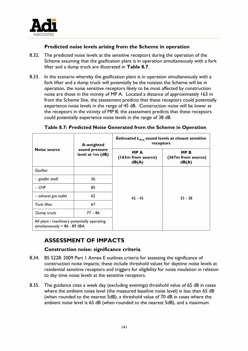
141
Predicted noise levels arising from the Scheme in operation
8.32. The predicted noise levels at the sensitive receptors during the operation of the
Scheme assuming that the gasification plant is in operation simultaneously with a fork
lifter and a dump truck are illustrated in Table 8.7.
8.33. In the scenario whereby the gasification plant is in operation simultaneously with a
fork lifter and a dump truck will potentially be the noisiest the Scheme will be in
operation, the noise sensitive receptors likely to be most affected by construction
noise are those in the vicinity of MP A. Located a distance of approximately 163 m
from the Scheme Site, the assessment predicts that these receptors could potentially
experience noise levels in the range of 45 dB. Construction noise will be lower at
the receptors in the vicinity of MP B; the assessment predicts that these receptors
could potentially experience noise levels in the range of 38 dB.
Table 8.7: Predicted Noise Generated from the Scheme in Operation
Noise source
A-weighted
sound pressure
level at 1m (dB)
Estimated LAeq sound levels at closest sensitive
receptors
MP A
(163m from source)
dB(A)
MP B
(367m from source)
dB(A)
Gasifier
42 - 45 35 - 38
- gasifier itself 56
- CHP 85
- exhaust gas outlet 62
Fork lifter 67
Dump truck 77 – 86
All plant / machinery potentially operating
simultaneously = 86 - 89 dBA
ASSESSMENT OF IMPACTS
Construction noise: significance criteria
8.34. BS 5228: 2009 Part 1 Annex E outlines criteria for assessing the significance of
construction noise impacts; these include threshold values for daytime noise levels at
residential sensitive receptors and triggers for eligibility for noise insulation in relation
to day time noise levels at the sensitive receptors.
8.35. The guidance cites a week day (excluding evenings) threshold value of 65 dB in cases
where the ambient noise level (the measured baseline noise level) is less than 65 dB
(when rounded to the nearest 5dB), a threshold value of 70 dB in cases where the
ambient noise level is 65 dB (when rounded to the nearest 5dB), and a maximum

142
threshold value of 75 dB in cases where the ambient noise level is higher than 65 dB;
the guidance also cites a noise insulation trigger value of 75 dB.
8.36. In the case of weekends, the guidance cites a threshold value of 55 dB in cases where
the ambient noise level is less than 55 dB (when rounded to the nearest 5dB), a
threshold value of 60 dB in cases where the ambient noise level is 55 dB (when
rounded to the nearest 5dB), and a maximum threshold value of 65 dB in cases
where the ambient noise level is higher than 55 dB.
8.37. Based on this guidance, the following criteria were used to assess the significance of
impacts of the construction of the Scheme on the noise climate at the sensitive
receptors during the week:
Not significant – if the noise level at the sensitive receptor does not exceed the
week day threshold value of 65 dB;
Minor significance – if the noise level at the sensitive receptor is equal to 65 dB but does not exceed the maximum week day threshold value and noise insulation
trigger for day time of 75 dB; and
Major significance – if the noise level at the sensitive receptor exceeds the maximum week day threshold value and noise insulation trigger for daytime of 75
dB.
8.38. The following criteria were used to assess the significance of impacts of the
construction of the Scheme on the noise climate at the sensitive receptors during the
weekend:
Not significant – if the noise level at the sensitive receptor does not exceed the
weekend threshold value of 55 dB;
Minor significance – if the noise level at the sensitive receptor is equal to 55 dB
but does not exceed the maximum weekend threshold value of 65 dB; and
Major significance – if the noise level at the sensitive receptor exceeds the
maximum weekend threshold value of 65 dB.
Prediction and significance of construction impacts
8.39. The predicted highest construction noise levels at MP A (63 dBA) and MP B (56 dBA)
could potentially exceed the maximum weekend threshold value (55 dB), however,
the levels are likely not to exceed 65 dB; hence, it is predicted that there would be a
minor impact on the sensitive receptors during the weekend during the noisiest stage
of the construction works.
8.40. The predicted highest construction noise levels at both MPs are below the week day
threshold value of 65 dB; hence, it is predicted that there would be no significant
impact on the sensitive receptors during the week during the noisiest stage of the
construction works.

143
8.41. It is highlighted that the construction noise impact assessment assumed the worst
case scenario for predicted noise levels, in assuming that all plant / machinery will be
operating simultaneously and continuously. In reality, it is unlikely that there will be
continuous noise output at the levels predicted throughout the excavation stage.
Furthermore, there was no allowance made for screening in calculating the predicted
noise levels at the sensitive receptors; in reality there will be some sound attenuation
by reason of existing buildings and structures in the intervening space, and through
the use of barriers on site. The construction site will necessarily be enclosed within
a masonry boundary wall, and there will be attention to reducing noise disturbance
within the sites through the timing of activities, which will serve to reduce the noise
levels at the sensitive receptors.
8.42. BS 5228: 2009 Part 1 Annex F gives guidance on approximate attenuation taking
account of the height of the noise source relative to the height of the barrier. As a
working approximation, if there is a barrier or other topographic feature between
the source and the receiving position, assume an approximate attenuation of 5 dB
when the top of the plant is just visible to the receiver over the noise barrier, and of
10 dB when the noise screen completely hides the sources from the receiver (BS
5228: 2009). In the case of both MP A and MP B, the machinery / plant on the site
will not be visible to the sensitive receptors. Hence, the predicted maximum noise
level at the sensitive receptors in the vicinity of MP A could potentially be reduced to
55 dB (65 dB – 10 dB). This would reduce the predicted noise level at MP A such
that the impact would be of no significance in relation to weekend impact.
Operational noise: significance criteria
8.43. BS 4142:2014 provides a methodology for rating and assessing sound of an industrial
and/or commercial nature and the likely effects of this sound. The significance of the
sound depends upon both the margin by which the specific sound level (operational
noise arising from the Scheme) at the sensitive receptors exceeds the background
sound level (baseline), and the context in which the sound occurs.
8.44. The assessment methodology outlined on BS 4142:2014 is based on obtaining an
initial estimate of the impact of the Scheme by subtracting the measured background
sound level from the rating level (the specific sound level which has been corrected
for character, such as tonality, impulsiveness, or intermittency, as necessary) and
using the difference to assess the magnitude of the impact. Typically, the greater the
difference, the greater the magnitude of the impact, as shown in Table 8.8.
Table 8.8: BS 4142:2014 Assessment criteria
Difference Assessment
Around +10 dB or higher Likely to be an indication of a significant adverse impact,
depending on the context
Around +5 dB Likely to be an indication of an adverse impact, depending
on the context,

144
The lower the rating level is relative to the measured background sound level, the less
likely it is that the specific sound source will have an adverse impact or significant adverse
impact. Where the rating level does not exceed the background sound, this is an
indication that the specific sound source will have a low impact, depending on the context
8.45. Based on the above, the following significance criteria were used in the initial
assessment of the significance of impacts of the noise arising from the operation of
the Scheme on the sensitive receptors:
Not significant (e.g. no material change in noise climate - a change of less than
+3dB to the background noise level at the sensitive receptor);
Minor significance (e.g. a change of between +3dB and +5dB to the background
noise level at the sensitive receptor);
Moderate significance (e.g. a change of between +6 and +9dB to the measured
background noise level at the sensitive receptor); and
Major significance (e.g. a change of +10dB or higher to the measured
background sound level at the sensitive receptor level at the sensitive receptor).
8.46. In accordance with BS 4142 (Section 11), the initial estimate of the magnitude of the
impact was then considered in relation to the noise context at the sensitive
receptors. Based on the initial estimate of the impact and this consideration of the
context, a final assessment was made of the significance of impacts of noise arising
from the operation of the Scheme, in terms of whether the impact is considered to
be not significant, of minor significance, of moderate significance or of
major significance.
Prediction and significance of operational impacts
8.47. In determining the rating level, as mentioned, BS:4142 (Section 9) advocates the
application of a penalty to the specific sound level, taking account of the acoustic
character of the specific sound (for example, tonality, impulsivity and intermittency),
where determination of the penalty is dependent on the degree to which these
features are present at the assessment location (in this case at the sensitive
receptors). The noises arising from the gasification plant, and from the fork lifter and
dump truck, are consider being predominantly tonal, but also with potentially
impulsive character. However, it is considered unlikely that these features are
present in the noise from the gasification plant, fork lifter or dump truck reaching
either MP A or MP B because the specific noise level in both cases does not exceed
the measured back sound level, and the noises which were observed to be
contributing to the noise environment (background sound level) at both monitoring
locations (noise from industrial activity and traffic noise) themselves have a tonal and
impulsive character. Hence, in the case of both MP A and MP B, the rating level has
been taken to be the specific sound level (45 dBA at MP A and 38 dBA at MP B).
8.48. In the case of MP A, the rating level (45 dBA) is 7 dB below the background sound

145
level (52 dBA). In the case of MP B, the rating level (38 dBA) is 12 dB below the
background sound level (50 dBA). As mentioned, the lower the rating level is relative
to the measured background sound level, the less likely it is that the specific sound
source will have an adverse impact or significant adverse impact. Based on the
assessment criteria outlined above, it is predicted that there will be no significant
impact from the Scheme in operation at the sensitive receptors in the vicinity of MP
A and MP B.
MITIGATION
8.49. In relation to construction noise impacts, the Construction Management Plan (CMP)
to be prepared by the Contractor responsible for the construction of the Scheme
should address the control of the noise impacts, including during the excavation stage
of the works. In addition to adhering to the provisions of the Environmental
Management Construction Site Regulations 2007, which will afford a measure of noise
mitigation, the CMP should detail working hours and the types of plant / machinery
to be used, as well as outline measures for the controlling of noise at source.
RESIDUAL IMPACTS
8.50. It is anticipated that noise arising from the excavation stage of the construction will
potentially be of minor significance at the sensitive receptors during the weekend.
The assessment assumed the worst case scenario however, in assuming that all plant /
machinery will be operating simultaneously and continuously during the excavation
stage. In reality, this is unlikely to be the case. Furthermore, there was no allowance
made for screening and, in reality, there will be some sound attenuation by reason of
existing buildings and structures in the intervening space, and through the use of
barriers on site. The attenuation taking account of these barriers / screens, as well as
noise control measures implemented through the CMP, is likely to reduce the scale
of the impact at all sensitive receptors to being not significant.

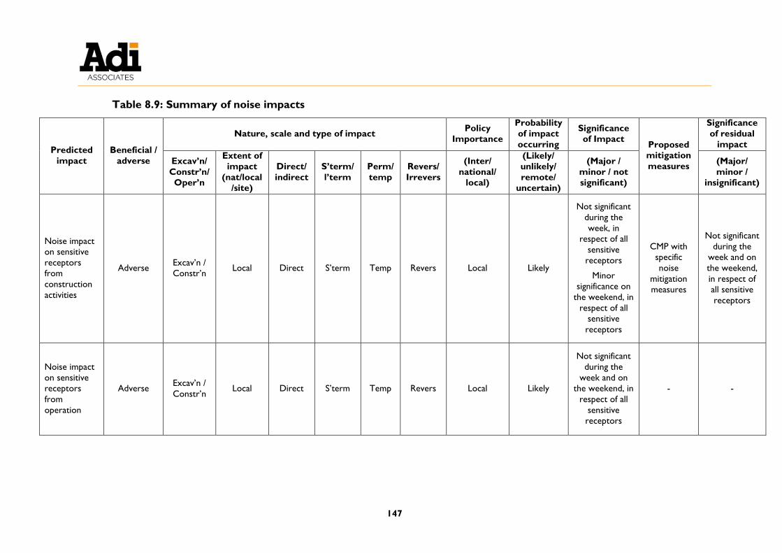
147
Table 8.9: Summary of noise impacts
Predicted
impact
Beneficial /
adverse
Nature, scale and type of impact Policy
Importance
Probability
of impact
occurring
Significance
of Impact Proposed
mitigation
measures
Significance
of residual
impact
Excav’n/
Constr’n/
Oper’n
Extent of
impact
(nat/local
/site)
Direct/
indirect
S’term/
l’term
Perm/
temp
Revers/
Irrevers
(Inter/
national/
local)
(Likely/
unlikely/
remote/
uncertain)
(Major /
minor / not
significant)
(Major/
minor /
insignificant)
Noise impact
on sensitive
receptors
from
construction
activities
Adverse Excav’n /
Constr’n Local Direct S’term Temp Revers Local Likely
Not significant
during the
week, in
respect of all
sensitive
receptors
Minor
significance on
the weekend, in
respect of all
sensitive
receptors
CMP with
specific
noise
mitigation
measures
Not significant
during the
week and on
the weekend,
in respect of
all sensitive
receptors
Noise impact
on sensitive
receptors
from
operation
Adverse Excav’n /
Constr’n Local Direct S’term Temp Revers Local Likely
Not significant
during the
week and on
the weekend, in
respect of all
sensitive
receptors
- -


149
9. ENVIRONMENTAL RISK ASSESSMENT
INTRODUCTION
9.1. This chapter presents an environmental risk assessment for the Scheme.
Terms of Reference
9.2. The Terms of Reference provided by MEPA in respect of environmental risk can be
viewed in Technical Appendix 1: Terms of Reference and Method Statements.
ASSESSMENT METHODOLOGY
Scheme phases
9.3. As described in Chapter 3, the Scheme will involve three major phases, as follows:
Construction;
Operation; and
Decommissioning.
9.4. The construction phase has been described in detail in Chapter 3. It is not foreseen
that construction will present significant environmental risk, given that most materials
to be handled will be inert in nature, and given that the construction phase will be
regulated by a Construction Management Plan, an outline of which has already been
presented. Therefore, it is considered that the environmental risk from this phase
does not need to be further assessed.
9.5. Decommissioning of the site will also follow an approved Decommissioning Plan, an
outline of which will be presented in the IPPC application that is being prepared
concurrently with this EIS. The outline plan will need to be further expanded and
updated in line with international practice and guidance applicable at the time of
decommissioning. It would be premature to carry out an environmental risk
assessment on the decommissioning phase at this stage, given that this will depend on
the state of the structures on Site at the time, the results of any site investigation, any
new receptors and pathways present at the time, and the nature of remediation
works to be carried out (if any). However, an environmental risk assessment can be
carried out as part of the eventual approval process of the full Decommissioning Plan,
if required by MEPA.
Objectives
9.6. This chapter therefore presents a detailed environmental risk assessment of the
Scheme operations by:
Describing and evaluating the risks to the environment associated with the
Scheme, including risks arising due to the nature of the materials and waste
proposed to be handled and stored, as well as the Scheme’s proposed waste
processing operations; and

150
Describing the measures which will be undertaken to mitigate such risks, and
evaluating the residual risk levels.
Methodology
9.7. The methodology used for risk assessment is based on that recommended by the
Institute of Petroleum.19
9.8. An environmental risk occurs when there is a means by which a hazard can result in a
deleterious impact on the surrounding environment, i.e. receptors. The presence of
a hazard alone does not constitute a risk. A risk is only present if there is a pathway
which links the source (hazard) to the receptor. This is known as the source-
pathway-receptor linkage.20
9.9. Environmental risk assessment is the process by which source-pathway-receptor
linkages are identified and evaluated. If any of the three elements are absent then
there is no complete linkage and thus no unacceptable risk.
9.10. To illustrate this, Figure 9.1 shows an example of a basic source-pathway-receptor
model associated with the operation of underground storage tanks. While the
Scheme will not include underground storage tanks, the methodology for identifying
source-pathway-receptor linkages is similar to that described in Figure 9.1.
19 Institute of Petroleum (2002) Guidelines for Soil, Groundwater, Surface Water Protection and Vapour Emission
Control at Petrol Filling Stations www.technokontrol.com/pdf/institute-petroleum-guidelines.pdf. 20 Defra (2002) Groundwater Protection Code: Petrol Stations and other Fuel Dispensing Facilities involving
Underground Storage Tanks
http://archive.defra.gov.uk/environment/quality/water/waterquality/ground/documents/groundwater-petrol.pdf.

151
Figure 9.1: Example source-pathway-receptor model20
Risk assessment criteria
9.11. If a source-pathway-receptor linkage is found, the magnitude of a risk is a function of
the consequences of pollution and the likelihood that such pollution will occur.
9.12. The risk criteria being applied to this assessment are based on a matrix consistent
with the Australian Standard AS4360 on Risk Management and ISO 31010: Risk
management: Risk assessment techniques.
9.13. Table 9.1 presents criteria for assessing environmental consequences, whereas
Table 9.2 presents criteria for assessing likelihood of the event occurring.
9.14. The overall risk level is then determined by combining the two factors, using the
matrix in Table 9.3.

152
Table 9.1: Criteria for assessing environmental consequences
Severity
level
Effects on natural environment
1: Insignificant Limited damage to minimal area of low significance.
2: Minor Minor effects on biological or physical environment. Minor short/medium-term
damage to small area of limited significance.
3: Moderate Moderate effects on biological or physical environment (e.g. air, water) but not
affecting ecosystem function. Moderate short/medium-term widespread impacts (e.g.
significant spills).
4: Major Serious environmental effects with some impairment of ecosystem function.
Relatively widespread medium-long term impacts.
5:
Catastrophic
Very serious environmental effects with impairment of ecosystem function. Long
term, widespread effects on significant environment (e.g. national park).
Table 9.2: Measure of likelihood
Level Descriptor Description Guideline frequency
A Almost
Certain
Consequence is expected to occur in most
circumstances
Occurs more than once per
month
B Likely Consequence will probably occur in most
circumstances
Occurs once every 1 month -
1 year
C Occasionally Consequence should occur at some time
Occurs once every 1 year -
10 years
D Unlikely Consequence could occur at some time
Occurs once every 10 years -
100 years
E Rare Consequence may only occur in
exceptional circumstances
Occurs less than once every
100 years
Table 9.3: Risk matrix
Likelihood Consequence
1: Insignificant 2: Minor 3: Moderate 4: Major 5: Catastrophic
A: Almost
Certain
Low Moderate Extreme Extreme Extreme
B: Likely Low Moderate High Extreme Extreme
C: Occasionally Very low Moderate High High Extreme
D: Unlikely Very low Low Moderate High High
E: Rare Very low Very low Moderate Moderate High
RISK ASSESSMENT
Overview
9.15. The Scheme’s operations will include storage and processing of hazardous substances
and waste which, without mitigation, could create a risk to the environment through
underground, surface and airborne pollution.
9.16. Table 9.4 summarises potential sources of pollution and the respective pathway to
the relevant receptors. The Table also includes the mitigation measures that will be
adopted to mitigate such risks, distinguishing between fixed structural elements

153
incorporated into the Scheme and procedural mitigation measures. It is to be noted
that all the mitigation measures in the Table will be implemented in the Scheme.
9.17. Table 9.5 identifies source-pathway-receptor linkages for major accident scenarios
of fire / explosion, flooding and earthquakes.


155
Table 9.4: Pollution pathway identification and mitigation measures
Source Pathway Receptor Mitigation Measures
Structural mitigation measures Procedural mitigation measures
Spillage of diesel / oils Permeable strata above
water table; rainwater
runoff
Land
Groundwater Entire site surface covered in concrete underlain
by a geotextile membrane.
The ground in outdoor areas of the site will be
laid to fall towards an oil-water interceptor
before being received in the reservoir.
Diesel / oil raw materials stored in
drums in a locked and bunded
shed.
WEEE motors stored in a bunded
area inside the main building.
Oily waste stored in a bunded
waste oil tank inside the main
building; oils from the interceptor
are typically retained in the
interceptor until collected.
Unauthorised waste to be stored
in indoor quarantine area.
An inspection and maintenance
programme for storage and
containment areas will be in place.
Spill prevention and response plan
and spill kits in place; staff training.
Metal emissions from
manual dismantling of
general WEEE and
storage of separated
components
Air dispersion (prevailing
wind direction);
wastewater from floor
washing; rainwater runoff
Air sensitive
receptors
Land
Groundwater
Entire site surface covered in concrete underlain
by a geotextile membrane.
Wastewater from any washing of floors in the
WEEE treatment building will be collected in
gutters, filtered to remove trace contaminants,
and received in an underground cesspit for
reuse.
Dismantling will occur indoors in
the main building; hazardous
components will be stored in this
building.
Unauthorised waste to be stored
in indoor quarantine area.
Mercury / phosphor
emissions from
fluorescent tube storage
and crushing
Air dispersion (prevailing
wind direction);
wastewater from floor
washing; rainwater runoff;
direct contamination of
Air sensitive
receptors
Land
Groundwater
Crusher installed inside a purposely built two-
room system with sealed windows.
Negative pressure unit linked to a HEPA filter
and an activated carbon filter.
Sealed vinyl flooring.
Operation of a water mister
inside the crushing room.
Incoming fluorescent tubes that
are received broken will be stored
inside crushing room.

156
Source Pathway Receptor Mitigation Measures
Structural mitigation measures Procedural mitigation measures
permeable strata above
water table (from
wastewater)
Wastewater will be treated using a specialised
impregnated filter to remove mercury, and
received in a sealed cesspit for reuse.
Entire site surface covered in concrete underlain
by a geotextile membrane.
Replacement of air and
wastewater filters in accordance
with maintenance schedule.
Monitoring of emissions as
required by IPPC permit.
Industrial vacuum cleaners
equipped with mercury filters will
be available to immediately clean
up any accidental breakages of
fluorescent tubes / lamps.
Metal / phosphor
emissions from breaking
of CRT neck
Air dispersion (prevailing
wind direction);
wastewater from floor
washing; rainwater runoff
Air sensitive
receptors
Land
Groundwater
CRT breaking room includes a negative pressure
unit equipped with a HEPA filter, room will be
fitted with a thick HDPE curtain.
Entire site surface covered in concrete underlain
by a geotextile membrane.
Broken CRT TVs / monitors
stored in jumbo bags in designated
area indoors.
Leakage of lead / acid
from batteries
Permeable strata above
water table; wastewater
from floor washing;
rainwater runoff
Land
Groundwater Entire site surface covered in concrete underlain
by a geotextile membrane.
Wastewater from any washing of floors in the
WEEE treatment building will be collected in
gutters, filtered to remove trace contaminants,
and received in an underground cesspit for
reuse.
Batteries stored in a container
inside the WEEE treatment
building.
Quantity of batteries stored
limited to 1 tonne.
An inspection and maintenance
programme for storage and
containment areas will be in place.
Used firefighting water
(generated in case of a
fire / explosion)
Permeable strata above
water table; rainwater
runoff
Land
Groundwater A 40 m3 chamber in the main reservoir (always
kept full for fire-fighting purposes) will provide
fire-fighting water; used water will be received in
different cesspits / reservoirs depending on the
area on site, as follows:
o Outdoor areas and inside the shed:
Reservoir (121 m3), after treatment in oil-
A fire and explosion prevention
and response plan will be
commissioned by the Applicant
once the Scheme has been
constructed.
A competent fire expert or
company will be engaged to

157
Source Pathway Receptor Mitigation Measures
Structural mitigation measures Procedural mitigation measures
water separator; any overflow will be of
treated water.
o WEEE treatment building: Received in
underground cesspit (around 13.5 m3) after
filtration. Therefore any overflow will be of
treated water.
Fire-fighting water will not reach the cesspit
receiving wastewater from fluorescent tube
crushing (as this will be connected directly to
the crushing equipment).
No storage of syngas; immediate combustion in
the CHP plant (thus reducing risk of fire).
advise on and install a fire
detection system and any
additional fire-fighting equipment
required.
Fire safety procedures and
equipment will be certified by a
competent fire expert or
company once they are in place.
Signage for safe operation will be
installed (e.g. no smoking signs).
Limiting the quantity of wood
stored to not more than 3 tonnes
when the gasifier is operational,
to reduce the risk of fire.
Table 9.5: Pollution pathway identification and mitigation measures for major accident scenarios
Scenario Source Pathway Receptor Mitigation Measures
Structural mitigation measures Procedural mitigation
measures
Fire /
explosion
Combustible material
(especially, syngas,
wood)
Air dispersion
(prevailing wind
direction)
Surrounding land users
(predominantly industrial
and agricultural)
No storage of syngas; immediate
combustion in the CHP plant.
A 40 m3 chamber in the main
reservoir (always kept full for fire-
fighting purposes) will provide fire-
fighting water.
Fire and explosion
prevention and response
plan.
Installation of a fire
detection system and any
additional fire-fighting
equipment required.
Fire safety procedures and
equipment to be certified.
Signage for safe operation.
Quantity of wood stored

158
Scenario Source Pathway Receptor Mitigation Measures
Structural mitigation measures Procedural mitigation
measures
limited to not more than 3
tonnes when the gasifier is
operational.
Flooding Storage and use /
processing of
hazardous substances
and waste
Permeable strata
above water
table
Land
Groundwater Entire site surface covered in concrete
underlain by a geotextile membrane.
The ground in outdoor areas of the
site will be laid to fall towards an oil-
water interceptor before being
received in the reservoir.
Impermeable cesspits.
All hazardous waste stored
in bunded areas indoors.
Waste processing occurs
indoors.
Diesel / oil raw materials
stored in a bunded shed.
Earthquake Storage and use /
processing of
hazardous substances
and waste
Permeable strata
above water
table
Land
Groundwater Only treated surface water /
wastewater will be received in the
underground reservoir and cesspits. Entire site surface covered in concrete
underlain by a geotextile membrane.
Secondary containment systems
for storage of hazardous waste.
and raw materials, as above.
159
Identification of potential releases
9.18. Releases could occur from accidental spillages of diesel, oils and oily waste stored and
handled on site, as well as leaks from vehicles / equipment and drips from
maintenance activities. The substances released would be hydrocarbon-based;
however, if the largest container is spilt entirely the maximum quantity released
would be limited to 50 L of diesel or hydraulic / engine oil, since storage beyond
these quantities will not be required.
9.19. Dismantling of general WEEE could result in the release of hazardous metal
components. However, most WEEE components (e.g. hard drives, printed circuit
boards) are solids and significant air emissions and metal leaching are not expected
under normal conditions. This activity, therefore, presents a minimal pollution risk.
9.20. Air emissions containing hazardous metals will also be generated from fluorescent
tube crushing and breaking of CRT monitors. Hazardous wastewater (contaminated
with mercury) will also be generated from washing of crushed fluorescent tubes.
Mitigation measures will, however, be in place to reduce air emissions and to treat
the wastewater.
9.21. Leaks of acid and lead from batteries could also result in a release; however,
considering that battery storage will be limited to 1 tonne the maximum release is
estimated at less than 100 kg. It is to be noted that even a release of this magnitude
would require a serious incident such as a forklift truck crashing into the battery
container.
9.22. Used firefighting water will also be generated in the event of a fire / explosion, and
without mitigation this may become contaminated with hazardous substances / waste
being stored on site.
9.23. A fire / explosion may be caused by the storage and handling of flammable substances
on site, notably syngas and wood. However, procedures will be in place to reduce
the risk of fire / explosion, including immediate combustion of the syngas in the CHP
plant, limiting the storage of wood to not more than 3 tonnes when the gasifier is
operational and having certified fire safety procedures and equipment in place at the
Scheme.
9.24. The storage and use / processing of hazardous raw materials and waste could also
result in a release of contaminants in the major accident scenarios of a flood or
earthquake.
Identification of migration pathways
Without mitigation
9.25. In the absence of mitigation, such as site containment, spills and leaks of diesel, oils,
hazardous wastewater from fluorescent tube washing, and lead / acid from batteries
could contaminate land directly and potentially also reach the groundwater through
the permeable rock strata underlying the site, although some attenuation is expected
due to the depth of rock above the groundwater. The same pathway would be

160
followed in the event of flooding or an earthquake.
9.26. Wastewater from washing of indoor areas could also become contaminated and
present a migration pathway.
9.27. Spills could also contaminate rainwater reaching the site, resulting in potential on-site
and off-site contamination of land (and eventually groundwater) through rainwater
runoff. A similar contamination scenario could occur if used firefighting water is
generated.
9.28. The pathway for air emissions would be air dispersion, particularly in the prevailing
wind direction, as well as contamination through precipitation of the pollutants in
rainwater. The pathway for fire / explosion would also be air dispersion.
With mitigation
9.29. A number of mitigation measures will be in place at the Scheme to prevent migration
of contaminants towards receptors, as described below and in Table 9.4.
9.30. The entire Scheme site will be concreted and lined with an underlying impermeable
geotextile membrane. As shown in Figure 3.15 (Chapter 3), the ground in outdoor
areas of the site and the shed floor will be laid to fall towards the main rainwater reservoir, and surface water (and any spills) from these areas will be treated in an oil-
water separator before being received in the reservoir. Spills can also be collected
by trained site operators using spill kits.
9.31. Wastewater from washing of floors inside the WEEE treatment building will be
collected in gutters, filtered to remove trace contaminants, and received in an
underground ventilated and impermeable cesspit for reuse.
86. The fluorescent tube crusher room will, however, have a dedicated 2 m3 cesspit.
Wastewater from tube crushing and floor cleaning will be treated using a specialised
impregnated filter to remove mercury, and received in this cesspit. The cesspit will
be sealed and the treated wastewater will be reused, thus creating a closed-loop
system. This room will also have sealed vinyl flooring.
9.32. The receipt of only treated water in the underground reservoir and cesspits will
reduce the risk of transfer of pollutants to land and groundwater in the event of an
earthquake.
9.33. Hazardous waste and raw materials will also be stored in designated bunded areas.
9.34. Crushing of fluorescent tubes / lamps will be carried out inside a purposely built
internal room located within a second outer room. The outer room’s windows will
be sealed to prevent unauthorised opening. In the internal room, a water mister will
be in continual operation to encourage wet precipitation of dust, and the room will
be equipped with a negative pressure unit, thus creating a seal. The exhaust air from
the negative pressure unit will include two filters in series, as follows:
A HEPA filter, having up to 99.97% filtration efficiency on particles 0.3 μm; and
161
An activated carbon filter impregnated with sulphur or iodine to enhance
mercury capture.
9.35. Fluorescent tubes and lamps will be stored in designated containers; tubes / lamps
that are received broken will be stored inside the fluorescent tube crushing room to
reduce the risk of fugitive emissions. Care will also be taken during storage and
handling to reduce the risk of breakage outside the crushing room; nonetheless,
industrial vacuum cleaners equipped with mercury filters will be available to
immediately clean up any accidental breakages of fluorescent tubes / lamps.
9.36. Breaking of the CRT neck will take place in a CRT breaking room that includes a
thick HDPE curtain with 1 – 2 inch overlapping panels, equipped with a negative
pressure unit connected to a HEPA filter.
9.37. Filters will be replaced at intervals in accordance with the maintenance plan, and an
air monitoring programme will be in place.
9.38. In the event of a fire / explosion, the underground reservoir will provide fire-fighting
water to contain and put out the fire as soon as possible; a 40 m3 chamber will always
be kept full for fire-fighting purposes. Used firefighting water from the outdoor areas
and shed will be collected in the same 121 m3 reservoir after treatment in the oil-
water separator, whereas used firefighting water from the WEEE treatment building
will be received in a 13.5 m3 cesspit after filtration. Any overflows (to the road
surface) will therefore be of treated water.
Identification of potential receptors
9.39. In the event of a spill or leak, in the baseline scenario the main receptor is the
underlying land. At the Scheme site, the exposed rock formation is Lower
Globigerina Limestone and Lower Coralline Limestone.
9.40. Contaminants could also eventually reach the groundwater in the unmitigated
scenario. The mean sea level aquifer is the principal hydrogeological feature in the
area, and the groundwater at the Scheme site is found at a depth of around 56 to 60
m below the land surface. As shown in Figure 5.5 (Chapter 5), there are seven
groundwater boreholes (six private, one public) located within around 400 m of the
site. However, in the event of a spill, some attenuation of contaminants is expected
even in the unmitigated scenario, considering that there is a considerable depth of
rock before the material is able to reach the groundwater.
9.41. Additionally, in the mitigated scenario, the pathway to the above land and
groundwater receptors will be removed, thus reducing the environmental risk
considerably.
9.42. The closest receptors sensitive to emissions to air from the Scheme are the
residences located approximately 180 m north of the Scheme site. Without
mitigation, air emissions may also be deposited onto land and eventually find their
way to the groundwater (although significant attenuation is expected before
contaminants reach groundwater).

162
9.43. The relevant receptors for a fire / explosion are the surrounding land users in the
immediate vicinity of the site, which are predominantly industrial and agricultural
users.
9.44. Additionally, in the baseline scenario the relevant receptors for used firefighting
water are the land and, to a lesser extent due to attenuation, the groundwater. With
mitigation, the pathway to receptors is removed since used firefighting water will be treated before being received in an underground reservoir / cesspit. Any overflows
will be of treated water, thus reducing the environmental risk.
Risk evaluation
9.45. The various risks on the environment are assessed using the evaluation criteria
described earlier.
9.46. The risks associated with both the unmitigated and mitigated scenarios are evaluated.
It should be noted that the Scheme proposes to include all the mitigation measures
described.
Without mitigation
9.47. Table 9.6 presents risk levels for each source without the mitigation measures.
Table 9.6: Risk levels without mitigation
Source Environmental
consequences
Likelihood of
consequence
Resultant
risk level
Spillage of diesel / oils Minor Likely Moderate
Metal emissions from manual dismantling of
general WEEE and storage of separated
components
Minor Likely Moderate
Mercury / phosphor emissions from
fluorescent tube storage and crushing
Major Almost certain Extreme
Metal / phosphor emissions from breaking of
CRT neck
Moderate Almost certain Extreme
Leakage of lead / acid from batteries Moderate Likely High
Used firefighting water Major Occasional High
Fire / explosion Major Occasional High
Contamination from flooding Major Unlikely High
Contamination from an earthquake Major Unlikely High
9.48. Leaks of diesel / oils from vehicles are rather common, although failure of storage
containers is less so. The environmental consequence is being considered as minor,
due to the small quantities in use / storage. The extent of any leak / spill would be
quite limited and localised.
9.49. Metal emissions from manual dismantling of general WEEE and storage of separated
components are being classified as minor, since most WEEE components are solids
and significant air emissions and metal leaching are not expected under normal
conditions. This scenario is being classified as likely, since while dismantling is a
routine operation at the Scheme, not all WEEE contain hazardous metals.

163
9.50. The environmental consequences of air emissions from fluorescent tube storage and
crushing are considered major, due to the particular hazards of mercury and the fact
that the glass will be finely crushed. The likelihood is almost certain since such
emissions are routinely expected from fluorescent tube crushing.
9.51. Air emissions from breaking of the neck of CRT monitors / screens are considered
to have moderate consequences, since there is no fine crushing of the monitor, thus limiting the generation and dispersal of fine particles. However, as such emissions are
routinely generated the likelihood has been classified as almost certain.
9.52. The environmental consequences of lead / acid emissions from batteries, if the
mitigation measures planned (including limiting the quantity stored) are not
implemented, are considered to be moderate. If batteries are not stored properly,
leakages to land / groundwater are routinely expected (typically in small quantities
but over a prolonged period), and therefore this scenario has been classified as likely.
9.53. Used firefighting water could result in major environmental consequences if
contaminated with hazardous substances, including mercury. The likelihood of a
major fire is occasional considering the flammability of the substances in storage (e.g.
wood) and the operation of the gasification / CHP plant, and the direct consequences
of a large fire could also be major.
9.54. The probability of a severe flood causing contamination has been classified as unlikely
following a review of Malta’s Preliminary Flood Risk Assessment, 21 in which the area
surrounding the Scheme site was not identified as being particularly susceptible to
flash flooding. Without mitigation, the environmental consequences of a flood could
be major, as contaminants could travel outside the site and contaminate the
surrounding land and underlying groundwater.
9.55. While a severe earthquake is also considered unlikely, the environmental
consequences could also be major in the unmitigated scenario.
With mitigation
9.56. Table 9.7 presents risk levels for each source with the proposed mitigation
measures.
Table 9.7: Risk levels with mitigation
Source Environmental
consequences
Likelihood of
consequence
Resultant
risk level
Spillage of diesel / oils Insignificant Likely Low
Metal emissions from manual dismantling of
general WEEE and storage of separated
components
Insignificant
Occasional
Very low
Mercury / phosphor emissions from Uncertain Almost certain Uncertain
21 Malta Resources Authority (2013) Preliminary Flood Risk Assessment http://mra.org.mt/wp-
content/uploads/2013/06/Preliminary-Flood-Risk-Assessment.pdf.

164
Source Environmental
consequences
Likelihood of
consequence
Resultant
risk level
fluorescent tube storage and crushing
Metal / phosphor emissions from breaking of
CRT neck
Insignificant Almost certain Low
Leakage of lead / acid from batteries Insignificant Occasional Very low
Used firefighting water Minor Rare Very low
Fire / explosion (immediate response) Minor Rare Very low
Fire / explosion (delayed response) Moderate Rare Moderate
Contamination from flooding Minor Unlikely Low
Contamination from an earthquake Minor Unlikely Low
9.57. Considering that the Scheme will have an impermeable hardstanding and oil-water
interceptor, together with specific bunding for oily waste, any spills / leaks would not
be able to contaminate the underlying land / groundwater as the pathway to the
receptor would have been removed. Therefore, the environmental consequence of
such a scenario is reduced to insignificant. Some minor leaks are still expected
regularly, especially from vehicle movements around the site, and therefore this
scenario has been classified as likely.
9.58. Since WEEE dismantling and hazardous waste storage will be undertaken indoors,
with wastewater from washing of floors being filtered, no significant metal emissions
are expected from these activities. The likelihood of metal emissions being generated
is classified as occasional, taking into account that the fact that significant metal
leaching is not expected even without abatement, and that not all WEEE contain
hazardous metals; however, air from the dismantling area is not specifically treated.
9.59. With mitigation, the environmental effects of CRT neck breaking are expected to be
insignificant, since the HEPA filter has a 99.97% filtration efficiency on particles 0.3
μm. Emissions are routinely generated during dismantling and thus the frequency has
been retained as almost certain.
9.60. Considering that the quantity of batteries stored will be limited and that the entire
site will be impermeable, with wastewater from floor washing being filtered, the
environmental consequences of a lead / acid leakage will be insignificant. The
occurrence of leaks will also be reduced through proper storage in a secondary
container, which will be checked regularly to ensure that its integrity is maintained.
9.61. The environmental consequences of used firefighting water are reduced to minor
with mitigation, since used water will be collected in the cesspit / reservoir and any
overflow will have been treated. The likelihood of a fire is reduced to rare, due to
the operational procedures that will be in place to limit the quantity of flammable
waste stored and risk of fire.
9.62. In the mitigated scenario, the environmental consequences of a fire / explosion would
be minor to moderate, depending on how quickly the fire is tackled (since the
response might be delayed if the fire occurs outside operating hours). This rating is
reduced from the unmitigated scenario, since the quantity of combustible material on

165
site will be reduced, and procedures and equipment will be in place to tackle a fire as
soon as possible and thus reduce the risk of it spreading beyond the site.
9.63. The probability of a severe flood or earthquake remain unlikely; however the
environmental consequences are expected to be reduced to minor with mitigation
measures in place.
Mercury emissions 9.64. The anticipated level of mercury emissions from fluorescent tube storage and
crushing could not be determined with certainty as the capture efficiency of the
mercury filter is not known. Studies that have been undertaken at the perimeter of
Applicant’s current site indicate that mercury emissions during tube crushing
currently reach 0.9 μg/m3. These emissions reflect a partly mitigated scenario that includes a two-room setup as is being proposed in the current Scheme, a HEPA filter
and impregnated charcoal filter in series, and a water mister. However, the roof of
the internal room is currently made of wood and the room itself is not airtight, as a
result of which negative pressure was not achieved during these tests. These studies
suggest that the Scheme’s proposed arrangements, which include two purposely built
and sealed rooms, and operation under negative pressure, will reduce emissions
further, although it is difficult to quantify the extent of these reductions.
9.65. The World Health Organisation (WHO)22 has estimated a tolerable concentration of
0.2 μg/m3 for long-term inhalation exposure to elemental mercury vapour, an annual
average guideline value for mercury in air of 1 μg/m3, and a tolerable daily intake for
total mercury of 2 μg per kg body weight. It is understood that MEPA requires
emissions from the Scheme not to exceed 0.2 μg/m3 at any time. While it is unclear whether this value will be achieved by the Scheme, even in a worst-case scenario
where emissions remain at the current 0.9 μg/m3, the closest residential receptors (located 180 m upwind of the Scheme site) are unlikely to be exposed to emissions
from the Scheme that exceed 0.2 μg/m3 at any time. However, the receptors’ actual exposure will also depend on current mercury baseline levels. Mercury levels at
MEPA’s urban background monitoring station at Żejtun are in the region of 2 ng/m3 (i.e. much lower than WHO guidelines), however, as the Scheme site is located next
to concrete batching plants, baseline emissions at the Scheme site may be higher than
this, due to the possibility of cement dust containing mercury. Baseline monitoring
for mercury will be undertaken as part of the IPPC application being prepared for the
Scheme.
9.66. Apart from considering impacts from direct inhalation, the significance of mercury
exposure also depends on the deposition rate and how it enters the food chain.
9.67. The WHO has also set a guideline value of 6 μg/L for inorganic mercury in drinking
22 World Health Organisation (2007) Exposure to Mercury: A Major Public Health Concern
www.who.int/phe/news/Mercury-flyer.pdf.

166
water.23 However, significant attenuation is expected before mercury emissions from
the Scheme reach the groundwater, since the groundwater at the Scheme site is
found at a depth of around 56 to 60 m below the land surface.
9.68. In view of these uncertainties, the environmental consequences of mercury emissions
from tube crushing has been categorised as uncertain. Since emissions are routinely
generated during tube crushing, the frequency has been retained as almost certain.
Conclusion and recommendations
9.69. As a result of the mitigation measures, environmental risks have largely been reduced
to very low to moderate.
9.70. However, the risk associated with emissions from fluorescent tube crushing and
storage is currently unclear and would depend on current mercury baseline levels
and the level of emissions from the Scheme. It is understood that baseline
monitoring will be undertaken as part of the IPPC application to establish current
mercury levels at the Scheme site, and that operational monitoring will also be
carried out periodically as part of IPPC requirements, to establish the effectiveness of
the proposed mitigation measures in reducing mercury emissions from the Scheme.
23 World Health Organisation (2011) Guidelines for Drinking-water Quality
http://whqlibdoc.who.int/publications/2011/9789241548151_eng.pdf.

167
10 SUMMARY OF KEY IMPACTS, INTERACTION
BETWEEN IMPACTS AND MITIGATION
INTRODUCTION
9.71. The purpose of this chapter is to provide a summary of the key environmental
impacts, their interaction and cumulative effects, and their mitigation. The chapter
addresses the requirements set out in the Terms of Reference (ToR) to describe
mitigation measures to “prevent, eliminate, reduce or offset (as relevant) the identified
significant adverse effects of the project” and to identify cumulative and residual impacts.
The chapter concludes with a summary of the mitigation measures proposed in the
Environmental Impact Statement (EIS).
SUMMARY OF KEY IMPACTS
9.72. Chapters 5 to 8 of the EIS describe the predicted impacts of the Scheme in relation
to geo-environment, landscape and visual amenity, ecology, and noise, in accordance
with the environmental topic areas identified in the ToR. Chapter 9 presents an
Environmental Risk Assessment.
9.73. For each predicted impact, an assessment has been made as to whether the impact is
likely to be of major, moderate (as relevant), or minor significance, or of no
significance; the criteria that were used to judge significance are described in each of
the chapters. Predicted impacts have been indentified, and, where relevant, there is a description of how these could be mitigated. All the residual impacts identified are
summarised in Table 10.1 at the end of this Chapter. It is noted that no significant
impacts were identified on landscape and visual amenity as well as noise receptors.
9.74. Potential major and/or minor impacts were identified on the geo-environment.
Excavation results in removal mineral resources for which the impact was described
as minor to major. The potential contamination of the ground water and surface
water run-off during operation were also described, however, with implementation
of mitigation measures, major significant residual impacts are unlikely. The
Environmental Risk Assessment also included an uncertain impact in relation to
mercury emissions.
INTERACTION OF IMPACTS
9.75. The interaction between impacts describes the potential cumulative or reactive
nature of the various disturbances caused by the Scheme during construction and
operation.
9.76. During construction, the only potentially minor to major impact identified in the EIS
relates to geo-environmental resources.
9.77. During operation, the main consideration is the risk that the facility will have on the
surrounding environment including risks to the groundwater, surface water, and risks
associated with toxic emissions.

168
CUMULATIVE IMPACTS
9.78. Cumulative impacts are those that result from incremental changes caused by other
past, present or reasonably foreseeable actions together with the Scheme. The
various impacts identified in Chapters 5 to 8 were assessed in the context of the
existing baseline (encompassing the past and present context.
9.79. In terms of potential cumulative impacts, the main concern is related to mercury
emissions as identified in Chapter 9. A concrete batching plant that is currently
operating in the vicinity of the Scheme site (see Chapter 3) may also be emitting
mercury, however, this has not been quantified. Cumulative impacts from mercury
vapour emissions from the Scheme site with those from the batching plant may result
in potentially significant mercury levels in the atmosphere in the vicinity of the site.
However, in the absence of a baseline scenario, the significance of such an impact is
uncertain at this stage. As part of the IPPC application process, a baseline mercury
scenario will be established through appropriate monitoring.
MITIGATION
9.80. The EIS, including its supporting Technical Appendices, reports the findings of the
EIA, in accordance with the ToR. Where appropriate, mitigation measures have been
recommended; these are described at the end of Chapters 5 to 8 and also in
Chapter 9. They are summarised in Table 10.1. It would be appropriate for, and
it is recommended that, these mitigation measures be taken account of in the
conditions of any eventual development permit.

169
Table 10.1: Summary of impacts
Predicted
Impact
Beneficial
/
Adverse /
Neutral
Nature, Scale and Type of Impact Policy
Importance
Probability
of impact
occurring
Significance
of Impact Proposed
Mitigation
Measures
Significance
of Residual
Impact
Constr’n /
Oper’n
Extent of
impact
(Nat/Local/
Site)
Direct/
Indirect
S-term
/
L-term
Perm/
Temp
Revers/
Irrevers
(Inter /
National/
Local)
(Likely,
Unlikely,
Remote,
Uncertain)
(Major,
Minor, Not
significant)
(Major,
Minor, Not
significant)
Geo-environment
Mineral
resources /
features
Adverse Constr’n Local Direct Long-
term Perm Irrevers Local Likely
Minor to
major
significance
Use of excavated
material in cement
manufacture and
use of clay in
landscaping and/or
for agriculture
Minor to
major
significance
Change in
quality of
ground water
Adverse Constr’n /
Oper’n Local Indirect
Short-
term /
Long-
term
Perm Irrevers Local Likely Minor to
major
Entire site lies on
an impermeable
surface, specific
bunding to capture
specific oil spillages,
oil-water
interceptors,
impermeable
cesspits
Not significant
Contamination
of surface
water runoff
Adverse Constr’n Local Direct Long-
term Perm Irrevers Local Likely
Minor to
major in case
of overflow of
used firewater,
depending on
extent of
overflow
otherwise not
significant
Used firewater
passing through
interceptor
Minor
significance in
case of
overflow of
used
firewater,
otherwise, not
significant

170
Predicted
Impact
Beneficial/
Adverse Nature, Scale and Type of Impact
Policy
Importance
Probability
of impact
occurring
Significance of Impact
(Major, Minor, Not
significant)
Proposed
Mitigation
Measures
Significance
of Residual
Impact
Extent of
impact
(Nat/Loca
l/Site)
Direct/
Indirect
S term/
L term
Perm/
Temp
Revers./
Irrevers
.
(Inter/Natio
nal/ Local)
(Likely,
Unlikely,
Remote,
Uncertain)
Legislation
In context
of Scheme
(Major,
Minor,
Insignificant
)
Ecology
Loss of habitat Adverse Local Direct L term Perm Irrevers. Local Likely EPA,
LN 311/2006,
GN 112/2007
Minor None Minor

APPENDIX 1: A3 PHOTOGRAPHS

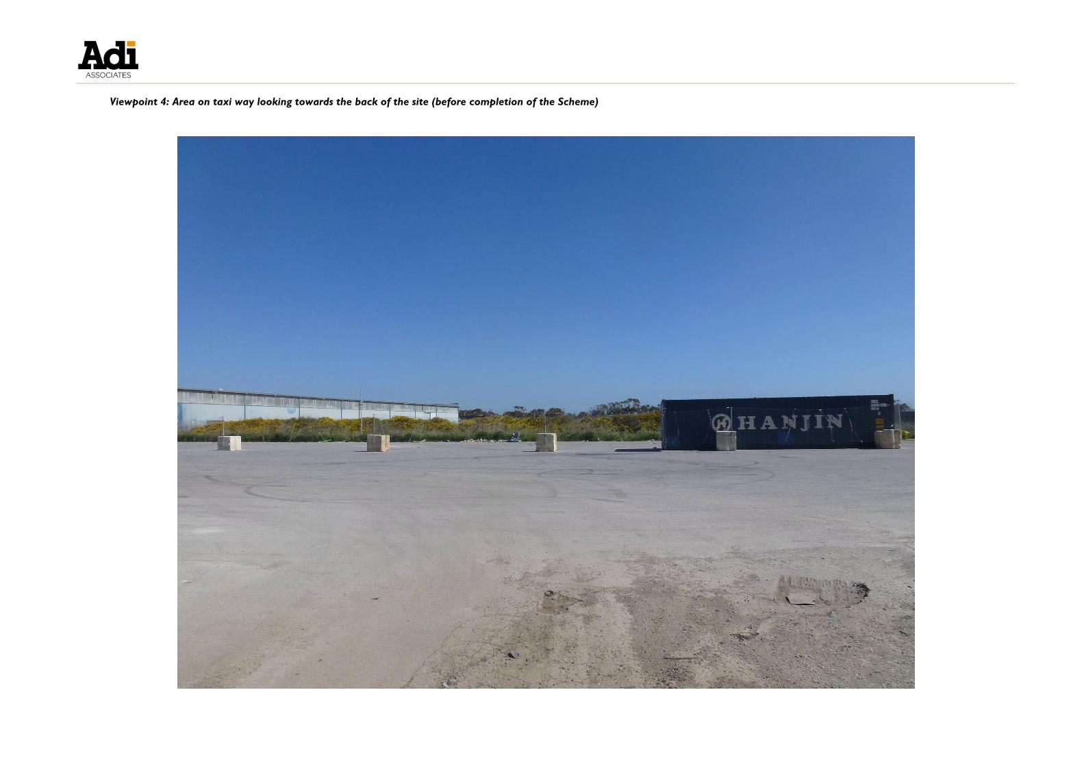
Viewpoint 4: Area on taxi way looking towards the back of the site (before completion of the Scheme)


Viewpoint 4: Area on taxi way looking towards the back of the site (after completion of the Scheme)


APPENDIX 2: ARCHAEOLOGICAL INVESTIGATION
TERMS OF REFERENCE

1 of 4
173, Triq San Kristofru, Valletta VLT 2000, Malta – Tel. No.: +356 23950000 – Fax No.: +356 23950555
23 April 2015
Our Ref. SCH 044/15
Permit Ref. TRK 159436
(EA00037/14)
To the attention of:
Mr Galea
Ref. Cultural Heritage Act (CAP 445)
Terms of Reference: Archaeology Investigation at HHF 040, Hal Far Qasam Industrijali,
Birzebbugia i.c.w. TRK 159436 (EA00037/14)
1. The archaeological investigation is to be undertaken in accordance to: the Superintendence
instructions, ‘Operating Procedures and Standards for Archaeology Services’ and the Cultural
Heritage Act.
2. The approved archaeologist will work under the direction of the Superintendence.
3. The approved archaeologist will communicate directly with the Superintendence.
4. Any other archaeologist/s required to provisionally assist the approved archaeologist are to be
approved by the Superintendence.
5. The developer is to provide any resources necessary, such as labourers and hand tools.
6. All spoil removed during this archaeological investigation is to be kept on site with a view to the
eventual rehabilitation of the site as might be necessary.
7. All costs related to the archaeology investigation are to be covered by the developer.
8. The intervention code for this intervention is: M 0 4 3 / 1 5
This intervention code is to be used for identification purposes on all documentation and
labelling related to this archaeological investigation.
9. Considering the archaeological sensitivity of the area, all site works are to be monitored by the
approved archaeologist in order to safeguard any cultural heritage remains which might be
uncovered.
10. The Superintendence reserves the right to take any measure it deems appropriate in order to
ensure the completion of the archaeological investigation.
11. The approved archaeologist is to keep the Superintendence regularly updated.
12. The archaeological investigation must be carried out according to the following stages:
12.1 Stage 1: Before Start of Works - Intervention Frequency: Inspections
12.1.1 The approved archaeologist must inspect the site prior to the start of site works.
12.1.2 Photos of the site before start of works are to be taken by the approved archaeologist.
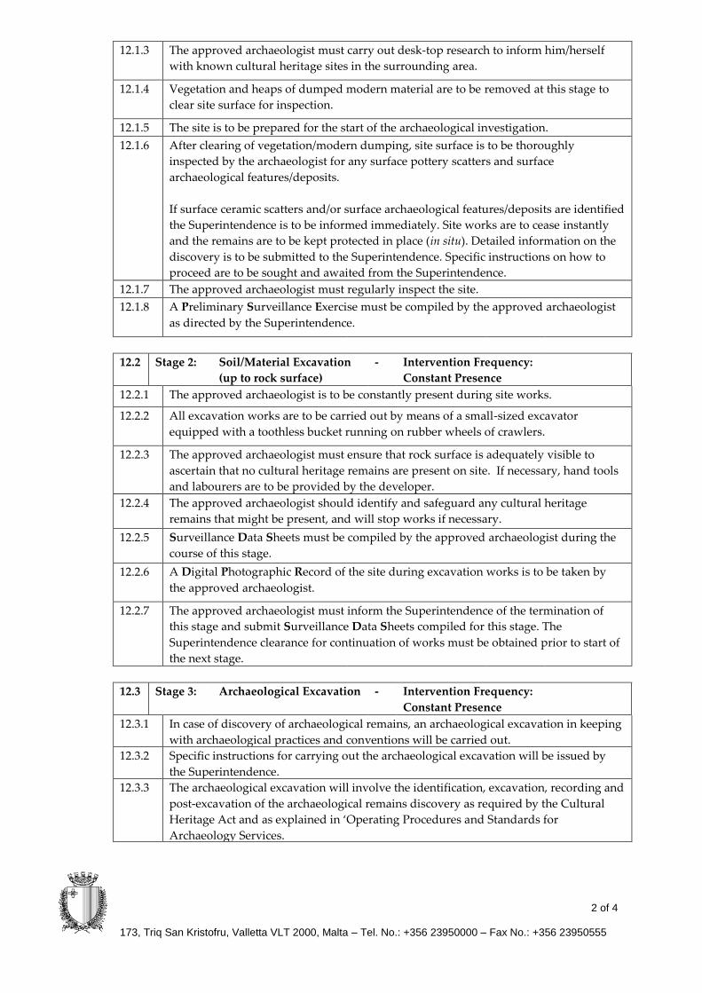
2 of 4
173, Triq San Kristofru, Valletta VLT 2000, Malta – Tel. No.: +356 23950000 – Fax No.: +356 23950555
12.1.3 The approved archaeologist must carry out desk-top research to inform him/herself
with known cultural heritage sites in the surrounding area.
12.1.4 Vegetation and heaps of dumped modern material are to be removed at this stage to
clear site surface for inspection.
12.1.5 The site is to be prepared for the start of the archaeological investigation.
12.1.6 After clearing of vegetation/modern dumping, site surface is to be thoroughly
inspected by the archaeologist for any surface pottery scatters and surface
archaeological features/deposits.
If surface ceramic scatters and/or surface archaeological features/deposits are identified
the Superintendence is to be informed immediately. Site works are to cease instantly
and the remains are to be kept protected in place (in situ). Detailed information on the
discovery is to be submitted to the Superintendence. Specific instructions on how to
proceed are to be sought and awaited from the Superintendence.
12.1.7 The approved archaeologist must regularly inspect the site.
12.1.8 A Preliminary Surveillance Exercise must be compiled by the approved archaeologist
as directed by the Superintendence.
12.2 Stage 2: Soil/Material Excavation
(up to rock surface)
- Intervention Frequency:
Constant Presence
12.2.1 The approved archaeologist is to be constantly present during site works.
12.2.2 All excavation works are to be carried out by means of a small-sized excavator
equipped with a toothless bucket running on rubber wheels of crawlers.
12.2.3 The approved archaeologist must ensure that rock surface is adequately visible to
ascertain that no cultural heritage remains are present on site. If necessary, hand tools
and labourers are to be provided by the developer.
12.2.4 The approved archaeologist should identify and safeguard any cultural heritage
remains that might be present, and will stop works if necessary.
12.2.5 Surveillance Data Sheets must be compiled by the approved archaeologist during the
course of this stage.
12.2.6 A Digital Photographic Record of the site during excavation works is to be taken by
the approved archaeologist.
12.2.7 The approved archaeologist must inform the Superintendence of the termination of
this stage and submit Surveillance Data Sheets compiled for this stage. The
Superintendence clearance for continuation of works must be obtained prior to start of
the next stage.
12.3 Stage 3: Archaeological Excavation - Intervention Frequency:
Constant Presence
12.3.1 In case of discovery of archaeological remains, an archaeological excavation in keeping
with archaeological practices and conventions will be carried out.
12.3.2 Specific instructions for carrying out the archaeological excavation will be issued by
the Superintendence.
12.3.3 The archaeological excavation will involve the identification, excavation, recording and
post-excavation of the archaeological remains discovery as required by the Cultural
Heritage Act and as explained in ‘Operating Procedures and Standards for
Archaeology Services.

3 of 4
173, Triq San Kristofru, Valletta VLT 2000, Malta – Tel. No.: +356 23950000 – Fax No.: +356 23950555
12.3.4
The approved archaeologist (site coordinator) is to be constantly present during the
archaeological excavation.
12.3.5 This archaeological excavation will require a team of archaeologists to be approved by
the Superintendence.
12.3.6 Surveillance Data Sheets must be compiled by the approved archaeologist during the
course of the archaeological excavation.
12.3.7 A Digital Photographic Record of the site during the archaeological excavation is to be
taken by the approved archaeology monitor.
12.3.8 The approved archaeology monitor must inform the Superintendence of the
termination of this stage and submit Surveillance Data Sheets compiled for this stage.
The Superintendence clearance for continuation of works must be obtained prior to
start of the next stage.
13. Surveillance Data Compilation
13.1 The approved archaeology monitor is to keep Surveillance Data Sheets for all stages of
works as outlined in ‘Operating Procedures and Standards for Archaeology Services’, in
line with the Cultural Heritage Act and as directed by the Superintendence.
13.2 A Digital Photographic Record of the site for all stages of works is to be kept by the
approved monitor.
13.3 Data compiled is to be submitted to the Superintendence at termination of works OR as
otherwise instructed by the Superintendence.
14. 14.1 In case of a discovery, the Superintendence is to be informed immediately. Site works are
to cease instantly and the remains are to be kept protected in place (in situ). Detailed
information on the discovery is to be submitted to the Superintendence as outlined in
‘Operating Procedures and Standards for Archaeology Services’, in line with the Cultural
Heritage Act and as directed by the Superintendence.
The Superintendence will intervene in terms of the Cultural Heritage Act, which
intervention shall not preclude any other measure contemplated under other Maltese
legislation.
Discovery of archaeological remains may require an archaeological investigation and
the amendment of approved plans.
14.2
Any movable material culture, archaeological remains and objects found during
archaeology monitoring are to be recovered as guided and directed by the
Superintendence.
Unless otherwise directed by the Superintendence, archaeology monitors are to ensure
that intact archaeological features and deposits are left and protected in situ in accordance
with the Cultural Heritage Act.
15. Any other data and material culture, archaeological remains and objects collected during site
works are the property of the State. These are to be gathered, finalised and deposited at the
Superintendence by the archaeology monitor as outlined in ‘Operating Procedures and
Standards for Archaeology Services’, in line with the Cultural Heritage Act and as directed by
the Superintendence.
16. Any work or action is to be undertaken in line with health and safety requirements as
established by local legislation. Persons on site must be equipped with the required health and
safety gear and equipment. Any work or action is to be certified safe by the health and safety
officer or architect in the latter’s absence. Service providers are to ascertain that health and safety
measures as indicated in OPSAS and in Occupational Health and Safety Authority Act are duly
applied.

4 of 4
173, Triq San Kristofru, Valletta VLT 2000, Malta – Tel. No.: +356 23950000 – Fax No.: +356 23950555
17. Written or verbal communications concerning outcomes of surveillance carried out by
archaeologists of the Superintendence of Cultural Heritage of and during authorised
construction or development, may not reflect and should not be construed as meaning or
reflecting, the considered position of the Superintendence with regards such construction and
development.
18. The approved archaeology monitor is to abide by any other instructions which may be issued
from time to time as necessary by the Superintendence.
Christian Mifsud
Cultural Heritage Executive
f/ Superintendent of Cultural Heritage