environmental impact assessment - asian development bank · environmental impact assessment project...
TRANSCRIPT

Environmental Impact Assessment Project Number: 37378-014 July 2017
Sri Lanka: Jaffna And Kilinochchi Water Supply Project, Additional Financing - Seawater Desalination Plant and Potable Water Conveyance System Prepared by the Government of Sri Lanka, National Water Supply and Drainage Board, for the Asian Development Bank. This environmental impact assessment is a document of the borrower. The views expressed herein do not necessarily represent those of ADB's Board of Directors, Management, or staff, and may be preliminary in nature. Your attention is directed to the “terms of use” section on ADB’s website.

ABBREVIATIONS
ACDP - Acoustic Doppler Current Profiler ADB - Asian Development Bank AMSL - Above Mean Sea Level BCE - Before Common Era BIQ - Basic Information Questionnaire BoD - Biochemical Oxygen Demand CC - Construction Contractor CCD - Coast Conservation Department CE - Common Era CEA - Central Environmental Authority DAF - Dissolved Air Flotation DBO - Design-Build-Operate DC - Design Contractor DGPS - Differential Global Positioning System DOA - Department of Archaeology DS - Divisional Secretary EC - Electrical Conductivity EEZ - Exclusive Economic Zone EIA - Environmental Impact Assessment EICC - East Indian Coastal Current EMP - Environmental Management Plan EMoP - Environmental Monitoring Plan EPL - Environmental Protection License ERD - Energy Recovery Devices ESMS - Environmental and Social Management System FI - Financial Intermediary FFPO - Fauna and Flora Protection Ordinance GCE - General Certificate of Education GDP - Gross Domestic Product GHG - Greenhouse Gas GN - Grama Niladhari GoSL - Government of Sri Lanka GPS - Global Positioning System GRC - Grievance Redress Committee GRM - Grievance Redress Mechanism GSMB - Geological Survey and Mines Bureau HDD - Horizontal Directionally Drilled HDPE - High-density Poly-ethylene H&S - Health and Safety H&SP - Health and Safety Plan IEE - Initial Environmental Examination IUCN - International Union for Conservation of Nature JKWSP Jaffna and Kilinochchi Water Supply Project LHI - Lanka Hydraulic Institute MENR - Ministry of Environment and Natural Resources MEPA - Marine Environment Protection Authority MHWN - Mean High Water of Neap Tides MHWS - Mean High Water of Spring Tides
MLWN - Mean Low Water of Neap Tides MLWS - Mean Low Water of Spring Tides MoU - Memorandum of Understanding MSL - Mean Sea Level NEA - National Environmental Act NEP - National Environment Policy NGO - Non-Governmental Organisation NMC - North Monsoon Current NWSDB National Water Supply and Drainage Board OC - Operations Contractor O&M - Operation and Maintenance P/DO - Provincial/District Office PAA - Project Approving Agency PC - Personal Computer PID - Provincial Irrigation Department PLC - Programmable Logical Controller PMCIU - Project Management, Coordination and Implementation Unit POP - Persistent Organic Pollutant PPE - Personal Protective Equipment RC - Reinforced Concrete RDS - Rural Development Society REA - Rapid Environmental Assessment RO - Reverse Osmosis RODP - Reverse Osmosis Desalination Plant RoW - Right of Way SCUBA Self-Contained Underwater Breathing Apparatus SD - Sri Lanka Dome SMC - South Monsoon Current SPS - Safeguard Policy Statement UF - Ultrafiltration UKMO - UK Meteorological Office WHO - World Health Organisation WICC - West Indian Coastal Current WRDC - Women’s Rural Development Society

CONTENTS
I. INTRODUCTION 1
A. Background 1
B. The EIA Study 5
II. POLICY, LEGAL AND ADMINISTRATIVE FRAMEWORK 7
A. ADB Policy 7
B. National Law 9
C. International Agreements 18
III. ANALYSIS OF ALTERNATIVES 19
A. Overview 19
B. Alternative Sources of Water Supply 20
C. Alternative Project Locations for Desalination Plant 25
D. Design/Process Alternatives for Desalination 30
E. Alternative Analysis for Transmission Main 48
IV. DESCRIPTION OF THE PROJECT 48
A. Project Overview 48
B. Plant Production Capacity 49
C. Project Components 50
D. Minimum Product (Potable Water) Quality & Brine Quality to be achieved 53
E. The Project Site 54
F. Indicative Project Implementation Schedule 60
G. Project Construction 62
H. Operation of the Completed Scheme 76
V. DESCRIPTION OF THE ENVIRONMENT 79
A. Overview 79
B. Physical Conditions 80
C. Biological Conditions – RODP Plant site 96
D. Biological Conditions – Along the Proposed Pumping Main Pipeline Alignment 129
E. Socioeconomic Conditions 135
VI. ENVIRONMENTAL IMPACTS AND MITIGATION MEASURES 153
A. Overview 153
B. Impacts due to Location of Project 154
C. Impacts due to Project Construction 163
D. Environmental Impacts & Mitigation Measures – Project Operation 189
E. Project Green House Gas (GHG) Emissions 208
F. Cumulative and Induced Impacts 208
G. Environmental Impact Matrix 209
VII. PUBLIC CONSULTATION AND INFORMATION DISCLOSURE 224
A. Consultation by the Project Proponent 224
B. Consultation by the EIA Consultant 226
C. Future Consultation and Disclosure 228
VIII. GRIEVANCE REDRESS MECHANISM 229
A. Key Principles and Practice 229
B. Project GRM and GRC 230

IX. ENVIRONMENTAL MANAGEMENT PLAN 233
A. Responsibilities for EMP Implementation 233
B. Environmental Management Plan 234
C. Environmental Monitoring Plan 260
D. Cost of EMP Implementation 266
E. Institutional Arrangements 267
F. Future Review and Revision of Documents 268
X. CONCLUSIONS AND RECOMMENDATIONS 269
A. Conclusions 269
B. Recommendations 271
APPENDICES (Available upon request)
Appendix A: ADB Environmental Safeguards Policy Principles, according to the Safeguard Policy Statement 2009
Appendix B: CEA Environmental Recommendation / Approval for Desalination Project in Jaffna Appendix C: CEA Terms of Reference for Environmental Study Report of Desalination Project
In Jaffna Appendix D: Schedule 1 of the marine environmental protection (issuance of permits for
dumping at sea) regulations no 1816/37 2013 Appendix E1: Executive Summary of Feasibility Study Report, 2006 Appendix E2: Feasibility Study Report, 2015 Appendix F: Probable Marine Construction Methodology Appendix G: LHI Field Investigation Report Appendix I: Phytoplankton Recorded at the Project Site (D-Dominant, >4.99%; M-
Moderate,1.00-4.99%; R-Rare, <1.00%) Appendix J: IUCN Sri Lanka Proposal on Translocation of Protected Marine Species Appendix K: LHI Numerical Modelling Report Appendix L: LHI Note on Impacts on Marine Species Due To Disposal Of Brine Appendix N: Outline of Contractor’s Construction Stage Environmental Management Plan Appendix O: Issues to Be Addressed in Contractor’s Operation Stage Environmental
Management Plan Appendix P: LHI Note on Protected Species In Project Site Appendix Q: Environmental Study Report Prepared by LHI Appendix R: Grievance redress form Appendix S: Terms of Reference of Independent Environmental Monitoring Specialist
LIST OF FIGURES
Figure 1: JKWSP Project Area 3
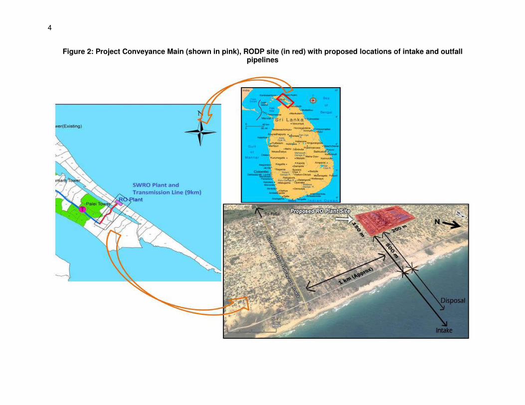
Figure 2: Project Conveyance Main (shown in pink), RODP site (in red) with proposed locations of intake and outfall pipelines 4
Figure 3: The Coastal Zone as defined by the Coast Conservation Act (1981) 13
Figure 4: The main proposals of the River for Jaffna Project (shown in yellow) 22
Figure 5: Potential project sites evaluated by the Feasibility Study 27
Figure 6: Coastal & Marine Conservation Areas 29
Figure 7: Proposed Alternative Locations of Intake and outfall 41
Figure 8: Near field plume model, and excess salinity 44
Figure 9: Brine dissipation of the Plume (Salinity) at 10 m depth Outfall IM2 Monsoon Average Condition 50% Recovery 46
Figure 10: Brine dissipation of the Plume (Salinity) at 10 m depth Outfall IM2 Monsoon Average Condition 50% Recovery Observed Maximum Spreading (Future Demand) 47
Figure 11: Schematic diagram of Seawater Reverse Osmosis Desalination Plant 51
Figure 12: Proposed SWRO Plant Site at Thalaiyadi 55
Figure 13: Proposed SWRO Plant Site & Access Roads 58
Figure 14: Potable Water Conveyance Pipeline Route 59
Figure 15: Indicative Project Implementation Schedule 61
Figure 16: New Approach Roads (in red line) & Existing road network in the project area 65
Figure 17:Conveyance Pipeline Alignment 76
Figure 18: Vertical intake tower with velocity cap recommended by Feasibility Study 77
Figure 19: Average annual (A) and monthly (B) rainfall in Jaffna, 2006-14 81
Figure 20: Topography of the project site (C) and the surrounding area (B) 83
Figure 21: Topography, surface water and drainage around the project site 86
Figure 22: Morphology and mechanism of recharge and exploitation of karstic aquifers on Jaffna Peninsula Key 87
Figure 23: Groundwater Aquifers in Northern Sri Lanka 88
Figure 24: Bathymetry and cross section of the coastal zone at the proposed site 90
Figure 25: Fluctuations in sea level recorded at the project site 19 March - 5 April 2016 91
Figure 26: Ocean circulation around Sri Lanka and southern India: (a) North-east monsoon; (b) South-west monsoon 92
Figure 27: Current rose diagram for (a) surface, (b) mid-depth and (c) seabed 93
Figure 28: Hydraulic Circulation and Current Field of the Proposed Project Area 94
Figure 29: Wave rose showing height, direction and percentage occurrence of near shore wave heights - annual distribution 95
Figure 30: Floristic Regions of Sri Lanka 97
Figure 31:Existing Forest Areas (2010) 99
Figure 32: Wildlife Conservation Areas in Northern Province 100
Figure 33: Major Lagoons in Jaffna Peninsula 101
Figure 34: Coastal & Marine Conservation Areas 102
Figure 35: The coastal marine habitats of Jaffna 113
Figure 36: Phytoplankton abundance (top), relative composition (middle) and species richness (bottom) at stations in the sub tidal area at the project site 124
Figure 37: Zooplankton abundance in the subtidal area at the project site 125
Figure 38: Local government administration in the project area: Jaffna District Divisional Secretary Divisions (top); Vadamarachchi East Grama Niladhari Divisions (bottom) 138
Figure 39: Ma Del Fishing Padus at Project Site 142
Figure 40: Allocated Padu for Intake & Outfall 143
Figure 41: Main Types of Fishing in Project Area 144
Figure 42: Ma Del Fishing Padus at Project Site 145
Figure 43: Ma del Fishing Padus in Project Area 199
LIST OF TABLES Table 1: Project-related international agreements to which Sri Lanka is a party 18
Table 2: Alternatives Considered for Jaffna Project 20
Table 3: Evaluation of alternative project sites by RODP Feasibility Study (ADB 2015) 28
Table 4: Evaluation of design/process alternatives by RODP Feasibility Study 31
Table 5: Evaluation of RODP Intake Alternatives 33
Table 6: Chemicals used in the RO treatment process 36
Table 7: Raw water intake and brine generation 37
Table 8: Basic input data used in the dispersion modeling 42
Table 9: RODP Project Components, as indicated in bid documents 51
Table 10: Minimum Pre-treatment Filtrate Water Quality Requirements 53
Table 11: Mandatory Quality Standards for RODP product water 53
Table 12: Tolerance Limits for Wastewater Discharge into Marine Coastal Areas 54
Table 13: Projected staffing of the operating RODP (source: FS Final Report, 2015) 78
Table 14: Ambient Day time Noise Level at Project Site 82
Table 15: Water Quality of domestic wells in Thalaiyadi North, 6 April 2016 88
Table 16: Published tidal levels for locations on the north-east coast of Sri Lanka (metres above Chart Datum) 91
Table 17: Average current speed and direction at the proposed outfall site, March/April 2016 93
Table 18: Terrestrial plants recorded at the project site and their conservation status 104
Table 19: Terrestrial animals recorded at the project site and their conservation status 106
Table 20: Coastal habitats of Sri Lanka, and the area (ha) of each in Jaffna District 111
Table 21: Species diversity in selected faunal groups in Sri Lankan coastal waters 114
Table 22: Marine species recorded during a diving survey at the project site 115
Table 23: Species diversity and abundance of the main groups of benthic infauna recorded at the project site in 2016 122
Table 24: Fish species observed during the diving survey at the project site 126
Table 25: Flora species along the pipeline alignment 132
Table 26: Reptilians recorded from Thalaiyadi – Soranpattu area. 132
Table 27: Avifauna species observed from the Soranpattu - Thalaiyadi area 133
Table 28: Mammal species observed from the Soranpattu - Thalaiyadi area 133
Table 29: Fish & Shrimp Species found in Vadamarachchi Lagoon 135
Table 30: Gender diversity in the three villages near the project site 139
Table 31: Age distribution of the population in the three local villages 140
Table 32: Religious diversity in the three local villages 140
Table 33: Fishing population and Fish Production –Maruthankerny GN division 147
Table 34: Typical Noise Levels (in dB) of Principal Construction Equipment 175
Table 35: Typical Chemicals used in the RO treatment process 194
Table 36: CO2 Emissions from RODP Operations 208
Table 37: Environmental Impact Matrix 210
Table 38: Stakeholder Meetings - Jaffna Kilinochchi Water Supply & Sanitation Project 224
Table 39: Stakeholder Meetings - Proposed Reverse Osmosis Desalination Plant 225
Table 40: Views expressed by stakeholders during informal discussions with the EIA consultant 226
Table 41: Pre-construction EMP Table 236
Table 42: Construction EMP Table 246
Table 43: Operation Phase EMP Table 256
Table 44: Environmental Monitoring Plan (Design & Construction Phase) 261
Table 45: Environmental Monitoring Plan (Operation phase) 264
Table 46: Estimated costs of EMP implementation 266
LIST OF PHOTOGRAPHS
Photo 1: Single track Mamune Road near the project site (south-easterly view) Photo 2: The project site, August 2016 Photo 3: Fishing huts north-west of the project site Photo 4: Applying a bitumen top coat to a new construction site access road Photo 5: Bulldozer and dump truck conducting earthworks Photo 6: Backhoe / sling bucket excavator loading a dump truck in a quarry Photo 7: Concrete production plant Photo 8: Steel reinforcing for building foundations and small structural columns Photo 9: Steel reinforcing encased in steel and plywood formwork Photo 10: RO building with concrete frame and steel sheet roof and walls Photo 11: RO membrane trains connected to pipework and power supply Photo 12: Aerial view of Adelaide RODP, Australia Photo 13: Pipeline being positioned into a trench with the aid of flotation buoys
Photo 14: Outfall pipe with array of duckbill diffusers, before installation Photo 15: Drainage from the project site, December 2015 Photo 16: Bathymetric and topographic survey Photo 17: Low dune habitat seaward of the project site, with creepers and shrubs Photo 18: Benthic species recorded in the diving survey: sponges, anemones, corals Photo 19: Benthic species recorded in the diving survey: gorgonians, molluscs, starfish Photo 20: Benthic species recorded in the diving survey: sand dollars, sea urchins, sea cucumbers Photo 21: Petersen grab being used to obtain sediment and infauna samples Photo 22: Two of the fish species seen at the project site Photo 23: B402 road crossing Vadamarachchi lagoon towards Thalaiyadi

EXECUTIVE SUMMARY
A. Background 1. The Jaffna and Kilinochchi Water Supply Project (JKWSP) aims to provide safe and reliable water and sanitation services to the Jaffna Peninsula and neighbouring Kilinochchi District in the north of Sri Lanka, areas that are economically disadvantaged and were badly affected by the recent civil war. They are also areas with limited surface water, and an almost total reliance on groundwater wells for domestic supply, which are prone to contamination by sewage, agricultural runoff and seawater intrusion. 2. Previous agreements with farmers to increase the capacity of Iranamadu irrigation tank south of Kilinochchi to allow additional abstraction for domestic supply have been rescinded because of fears that agriculture would suffer in dry years. With the Jaffna population projected to increase by 50% to 900,000 by 2030, the Government has investigated alternative sources, of which seawater desalination was the only sustainable, drought-proof option. A Feasibility Study (FS) in 2014-15 recommended construction of a 24,000 m3/day seawater reverse osmosis desalination plant (RODP) on the north-eastern coast of Jaffna Peninsula, to supply drinking water to 300,000 people, providing a partial solution that could be expanded to deliver an almost total solution in the future. 3. The RODP will be developed by a Design-Build-Operate (DBO) contract, in which the contractor is responsible for all elements of the scheme design and construction, and will operate the plant for the first 7 years. This contract also includes creation of potable water storage in the RODP including pumping infrastructure and a 8 km potable water conveyance pipeline from RODP to existing water main on Jaffna – Kandy highway. Bidding process is currently underway, and is likely to be awarded late 2017, after which there is a 6-month design period and 2 years of construction, to completion in mid 2020. The project is financed by a loan from the Asian Development Bank (ADB). The National Water Supply and Drainage Board (NWSDB) is the Executing Agency and the Implementing Agencies are the Ministry of City Planning and Water Supply and the Ministry of Provincial Councils and Local Government. A Project Management, Coordination and Implementation Unit (PMCIU) is established in Jaffna city to implement the project. 4. ADB has classified the project as environmental Category A (the highest category), because it involves construction and operation of a large industrial complex at a coastal greenfield site and is therefore expected to have significant adverse impacts. An EIA study was conducted between December 2015 and July 2017 and this document is the EIA report. The study and report are intended to comply with ADB’s Safeguard Policy Statement (SPS) 2009, and it is anticipated they may also fulfil the requirements of Sri Lankan EIA law. B. Analysis of Alternatives 5. Jaffna Peninsula is in Sri Lanka’s dry zone, where rainfall is <1250 mm per year and falls mainly in the northeast monsoon (October-December). This does not create permanent rivers, and the flat topography does not allow retention of significant runoff by damming drainage channels. The River for Jaffna Project, which aims to convert Jaffna’s brackish lagoons into freshwater reservoirs via saline exclusion structures, has yet to prove successful, so Iranamadu is the only large surface water resource in the region. Capacity expansion to allow abstraction for domestic supply remains an aim of NWSDB, but this is not achievable in the short term, so there is no prospect of alternative surface water sources.

ii
6. A porous limestone geology means that Jaffna is quite well provided with aquifers, but the limited rainfall and proximity of the ocean means that rainwater floats as lenses on top of denser seawater, so excess recharge flows to the ocean in the rainy season and wells become salinized when over-pumped in the dry season. Increased groundwater abstraction would therefore not be advisable. Earlier studies investigated other technologies, including improved management of existing resources and expanding water harvesting schemes, but these would not come near to satisfying the projected demand. Seawater desalination by reverse osmosis is the only feasible method of providing an adequate supply. 7. The FS examined six alternative sites for the RODP and chose Maruthankerny/Pallai because it is not particularly sensitive in socio-economic or environmental terms (sparsely populated, limited agriculture and no artefacts of religious/cultural significance; no coral, sea grass or other important marine habitats), has a favourable seabed profile and depth, and offers cost savings because of closer connections to the power grid and water distribution system. The FS examined alternatives for most aspects of the process technology and gave recommendations based on suitability, cost and environmental factors. C. The Project 8. The RODP will occupy an area of around 4 ha (200 x 200m), and seawater will be sourced from the adjacent coastal zone at a depth of around 10 m, with the brine effluent returned to the sea through diffusers to ensure rapid mixing and dispersal. Site is 500 m from the beach, and the pipelines will extend 500 m (outfall) and 800 m (intake) into the sea and maintaining least 300 m between water intake and brine disposal outfall. The components and their main features are as follows:
COMPONENT KEY CHARACTERISTICS
Seawater intake
-Circular concrete tower, 2 m diameter, with fixed grill type screen (size of openings 75 mm or less, measured diagonally); a velocity cap arrangement (maximum entry velocity 0.15 m/sec & creating horizontal flow direction at the entrance). -Single inlet to HDPE pipe (600 mm dia), buried 2 m below seabed -Length of intake pipe: 1,300 m – from Intake tower in sea to intake pump station at RODP; 800 m of pipeline buried under sea bed, remaining will be buried under the land between sea and RODP site
Intake pump station (onshore, within RODP site)
-Wet well, surge chamber with vertical turbine pumps directly overhead -Intake screens - mechanical screening equipment (rotating band screens with max 2 mm band width) upstream of the intake pumps; -Pump well with all required flood-prevention sumps & all required controls (wet or dry) -Seawater intake pumps and transfer pipework
Pre-treatment facility
-Filtration (“pressured” or “submerged” membrane filtration and “gravity” or “pressurised” granular media filtration – to be finalized by DBOC). -Provision for Dissolved Air Flotation(DAF) system for algal blooms - Cartridge filtration
Reverse Osmosis (RO) System
-- Capacity 24 MLD (potable water output) with space provision to upgrade to 48 MLD in future - RO membrane process of single pass works (with a provision for additional membranes to reduce the boron level if required) RO Components: (i) RO feed water conditioning facilities, (ii) 4 RO trains of 6 MLD each,
(iii) membrane cleaning system, (iv) membrane flushing system, (v) Isobaric Pressure-exchanger type Energy Recovery System.
Post-treatment system - Remineralisation: Lime and carbon dioxide
iii
COMPONENT KEY CHARACTERISTICS
- Disinfection: Chlorine gas
General service facilities and ancillary & support services at RODP
-Chemical storage facilities -Administrative building (office, conference, auditorium, restrooms, workshop, etc.) -Water quality laboratory -Circuit bungalow -Staff quarters -Paving, parking, landscaping etc., -2 new access roads (total length ~1000 m length 2 lane) - Ancillary & support services (service air, instrument air, fire safety, safety equipment, water etc.,) - sanitary waste collection and treatment facilities (septic tank)
Potable water storage & conveyance
-Above-ground, concrete tank; volume 10,000 m3
-On-site Pump Station to convey potable water to delivery point – High lift pumps (2x6 MLD + 3x12 MLD pumping capacity) with high-efficiency motors & variable frequency drive control -Potable water conveyance main (8km - 800 mm diameter DI pipe) tank to delivery point at Puthukkadu Junction, Jaffna – Kandy Road
Liquid waste streams Spent pre-treatment backwash water; sludge from lime saturators; spent RO membrane cleaning water. Collected in discharge retention tank, neutralised by adding lime water, sulphuric acid or sodium bisulphite, and discharged to the sea with the brine effluent
Discharge (outfall) facilities -Discharge retention tank, with mechanical mixers /recirculation pumps, & feed lines (for sodium hydroxide, sulphuric acid & sodium bisulphate)
Discharge outfall: -Single HDPE outfall pipe (600 mm diameter, buried 2 m below seabed) with diffusers on the seabed (0.5 – 1m projection), 500 m from the beach and at least 300 m from the intake
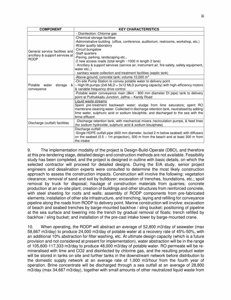
9. The implementation modality of the project is Design-Build-Operate (DBO), and therefore at this pre-tendering stage, detailed design and construction methods are not available. Feasibility study has been completed, and the project is designed in outline with basic details, on which the selected contractor will proceed for detailed designs. During the EIA study, senior project engineers and desalination experts were consulted to determine the most likely construction approach to assess the construction impacts. Construction will involve the following: vegetation clearance; removal of sand and soil by bulldozer; excavation of trenches, foundations, etc.; spoil removal by truck for disposal; haulage of construction materials from quarries; concrete production at an on-site plant; creation of buildings and other structures from reinforced concrete, with steel sheeting for roofs and walls; assembly of RODP components from pre-fabricated elements; installation of other site infrastructure, and trenching, laying and refilling for conveyance pipeline along the roads from RODP to delivery point. Marine construction will involve: excavation of beach and seabed trenches by barge-mounted backhoe / sling bucket; positioning of pipeline at the sea surface and lowering into the trench by gradual removal of floats; trench refilled by backhoe / sling bucket; and installation of the pre-cast intake tower by barge-mounted crane. 10. When operating, the RODP will abstract an average of 52,800 m3/day of seawater (max 58,667 m3/day) to produce 24,000 m3/day of potable water at a recovery rate of 45%-50%, with an additional 10% abstraction for filter washing, etc. At ultimate design capacity (which is a future provision and not considered at present for implementation), water abstraction will be in the range of 105,600-117,333 m3/day to produce 48,000 m3/day of potable water. RO permeate will be re-mineralised with lime and CO2 and disinfected by chlorine gas, and the resulting product water will be stored in tanks on site and further tanks in the downstream network before distribution to the domestic supply network at an average rate of 1,000 m3/hour from the fourth year of operation. Brine concentrate will be discharged through a sea outfall at an average of 28,800 m3/day (max 34,667 m3/day), together with small amounts of other neutralized liquid waste from
iv
the treatment process (backwash water from cleaning filters and screens, sludge from lime saturators, and spent cleaning fluid from RO membranes). In ultimate design phase, brine discharge will be 57,600-69,333 m3/day. 11. The plant will be equipped with highly automated monitoring and control systems and will operate continuously with a staff of around 28, of whom a minimum of 2 operators and security staff will run the plant at night, weekends and holidays. Normal operation will involve collection/analysis of data on water quality at the intake, treatment house and outfall; and control/monitoring of all processes, equipment and facilities. Maintenance requires regular replacement of cartridge filters, RO membranes and other components and consumables. All operation and maintenance (O&M), site safety, risk management, etc. will be conducted according to procedures set out in O&M Manuals, on which extensive training will be given.
D. The Existing Environment
Sector Existing Conditions
Climate Jaffna Peninsula is in Sri Lanka’s dry zone, where average rainfall is 1000-1250 mm/year. Daily average temperature is 26.3 °C in December/January and 30.9 °C in May. The northeast monsoon brings high wind, and rainfall of >200 mm/month in October-January, but rainfall is < 80 mm/month in the rest of the year
Air Quality Air quality has not been measured in Jaffna, but with low traffic, no heavy industry and good dispersion by sea breezes, air quality will almost certainly be high, except for possibly some dust blown by monsoon wind
Topography and Soils
Jaffna Peninsula is low (max 11 m) and flat, with coastal landforms, and soils a mixture of marine deposits and wind/ wave derived sediments. The project site is on a 1.5 km wide strip of land on the northeast coast between Vadamarachchi Lagoon and the Bay of Bengal. The site is low-lying (max 3.5 m) and flat, with a deep surface covering of sandy, white unconsolidated soil. Potable water conveyance main is proposed along an existing main road. Topography of the alignment plain.
Geology Jaffna was covered by seawater up to the Miocene and the limestone geology derives from coral reefs. The limestone is 50-90 m thick, with Mannar sandstone below and a discontinuous layer above. Limestone solubility produces numerous underground solution caverns, which contain the main groundwater reserves. Surface soil is sandy, only 15 mm deep in places, reaching a maximum of 8-17 m around the project area
Surface Water and Drainage
The peninsula has no permanent rivers because of the flat terrain and limited rainfall, and there are no land forms suitable for reservoir development. Some natural depressions have been enhanced by bunds and soil removal and these and other “tanks” and “ponds” feed a cascade system of small canals and ditches to irrigate fields and recharge groundwater. Excess rainfall drains to the 4 large internal lagoons and the sea. Vadamarachchi lagoon is closest to the RODP site (1.5km), and conveyance pipeline crosses this lagoon.
Groundwater Groundwater is the only source for domestic supply on the peninsula and is also used in agriculture in the dry season. Four karstic aquifers (below each main land mass) hold the main reserves and shallow sand aquifers hold some monsoon rain. All are replenished by November-December rain and diminished by abstraction thereafter, when salinization and contamination by sewage and agricultural fertilizers are issues in some areas. Limited data from wells near the project site shows an adequate quality for domestic use
Coastal Bathymetry
Surveys by this project show that the sea area adjacent to the project site has a sandy bed that slopes quite steeply (1:25) down to 7 m depth at 250 m, after which the slope gradually becomes gentler, reaching 12.1 m at 1250 m offshore. This is a fairly typical profile for an open coastal area, exposed to moderate waves
Tides Like the rest of the east coast of Sri Lanka, the project site has a semi-diurnal tidal regime (2 high and low tides a day) with different heights. The tidal range is 0.6 m (MLWS 0.1 - MHWS 0.7) and MSL is 0.37m CD
Currents In the northeast monsoon the North Monsoon Current flows east to west along the equator, drawing the East Indian Coastal Current south along Sri Lanka’s east coast. In the southwest monsoon, the South Monsoon Current flows west to east and an anti-clockwise eddy forms off the east coast of Sri Lanka, maintaining the southerly flow. However surveys show that currents at the project site flow to the northwest (max 0.364 m/s)
v
Sector Existing Conditions
Waves Data from international meteorological models, transformed to simulate shallower inshore depths show that waves with a height >1 m approach the project site from the north-east during the NE monsoon in November -April. Average wave heights are 0.25 m and maxima 1.75 so this is not an area with severe wave action
Seawater Quality
A survey for this project showed that seawater quality at the project site is good, with low suspended solids (<2 mg/l) and organic matter (<5 mg/l BoD5) and no evidence of oil, heavy metals, faecal bacteria, pesticides.
Terrestrial Flora Sri Lanka has diverse habitats/species, mainly in wet/intermediate zones in the south. In the dry zone, Jaffna is a species-poor area, with just 2 of the country’s15 floral zones. The project site is in a large band of coastal and marine belt and surveys showed the area is low-form dunes, with scrub vegetation of 2-4 m high shrubs, small trees and a ground flora of creepers and succulents. One species (bitter gourd) is Vulnerable according to the national red data list and 3 other Near Threatened species are reported in the vicinity.
Terrestrial Fauna
Surveys showed a variety of animals at the project site, mostly those common in scrub habitats. Birds were from various habitats/niches, including waders/water birds that feed on the beach and inshore areas; and mammals and reptiles mainly occupy burrows. Two of the birds (painted stork; spot-billed pelican) are Near Threatened; and two reptiles reported in the vicinity are Endangered (salt-water crocodile; hawksbill turtle). Salt water crocodile is of least concern as per IUCN red list, but protected under national level. Presence of hawksbill turtle not fully confirmed. There are 3 more species of conservation status in the area around the conveyance main alignment: Macacasinica (Toque macaque) – endangered, and two near threatened species (Ratufamacroura (Sri Lankan Giant Squirrel) and Semnopithecuspriam (Gray Langur). As pipeline is to be laid along the road within its RoW no interference envisaged. Salt water crocodile presence is reported in the lagoon along which pipeline to be laid.
Marine Benthos Jaffna has a high marine diversity, although not at the project site as sand is a low productivity habitat. Grab surveys found a typical infauna (live below the sand surface) of worms, molluscs and crustaceans; and diving surveys reported just 16 species of epifauna (live on the seabed) and few fish. Four of the epifauna are protected by the national Fauna and Flora Protection Ordinance (2009) to prevent aquarium exploitation
Plankton Surveys found a typical phytoplankton at the project site, with 92 taxa, mainly diatoms and dinoflagellates, in an average density of 279-866 individuals/litre. The zooplankton was also typical, with 71 taxa, dominated by copepods (53%), and crustacean larvae (10%). The dominance of diatoms and copepods is normal in the coastal plankton and the high species diversity indicates a healthy population and good water quality
Fish and Fishing
The diving survey found only five, mainly small-sized fish species, and reported no shoals or commercially-exploited species. In contrast, leaders of fishing associations described a diverse fishery, with Ma del seine netting and weighted rolling nets for murex shells on the inshore seabed; and lobster traps, squid harvesting, and line and net fishing for jacks, groupers and snappers on offshore reefs. Madel returns were said to be 100-150 kg/day, but other reports suggest that the inshore methods may have damaged seabed habitat
Socio-economic Context
Sri Lanka’s economy has been buoyant since the civil war ended, when Government reconstruction and development has stimulated economic growth of 6.4%. The country has transitioned from an agricultural to a service base and per capita income rose from $1000 in 2004 to $3934 in 2015. Change has not yet reached the Northern Province where agriculture and fishing are the main occupations and poverty remains evident
Maruthankerny Vadamarachchi East is the second largest Divisional Secretary Division in Jaffna District and extends along most of the eastern coastline. Maruthankerny is its largest Grama Niladhari Division, with a population of 1,351, in three villages near the project site: Thalaiyadi (502); Maruthankerny North (478) and South (371)
Demo-graphics There is no inhabitation at or near the project site and Thalaiyadi is the nearest village, 750 m away. Potable water conveyance pipeline traverses Thalaiyadi and Maruthankerny villages. There are 459 families in the 3 villages, with a family size of 3 and sex ratio of 1:1, except in Maruthankerny South where there are 37 more females than males. Age distribution is normal, although lower numbers in the >55 group suggests a life expectancy below the national average. The population is all Sri Lankan Tamil; and Thalaiyadi is 100% Roman Catholic, whereas Maruthankerny N and S are 90% Hindu and 10% Catholic
Socio-economics
Fishing supports all of the families in Thalaiyadi, 90% in Maruthankerny N and 60% in Maruthankerny S; and the other occupation is agriculture. Educational standards are lower than in urban parts of Jaffna where there has been more investment in post-war rehabilitation. 19-20 people were killed in the civil war and 60 or more in the tsunami of 2004, when all houses in Thalaiyadi and Maruthankerny
vi
Sector Existing Conditions
North were destroyed. Both villages were rebuilt 300 m inland and each family was given a new house and plot of land of 750-1000 m2
Infrastructure The A9 is the main road onto Jaffna peninsula, and the first right-hand junction is the B402, which runs 7 km to Thalaiyadi on the coast. The B371 branches off the B402 and runs 30 km north-west to Point Pedro. The B-roads carry most local motorised traffic, are around 7 m wide and are not well maintained. Most houses have a 3-phase power line, but there is no piped water and all houses use groundwater from shallow wells. There are public offices in the villages (District Secretariat, GN Office, rural hospital) but no large shops.
History and Culture
Jaffna was probably inhabited from prehistoric times, and key periods in its later history include: the 1,700 year Rajarata era; Jaffna Kingdom from 1215; and the colonial period from 1619 to independence in 1948. Relics are displayed in Jaffna Archaeological Museum (Nallur), and colonial buildings stand in the city today. Several archaeological studies were conducted in Jaffna in the 20th century and there are recent reports of a settlement from 1st millennium BCE in Vadamarachchi East, but the site location is not yet available. Cultural sites in the local villages include Shakthi Kovil, St Anthony’s church, Tsunami memorial, 2 community halls.
General Social Issues
During consultations for this study, local people raised certain social issues not directly related to the project: There is no storm water drainage system in local villages or alongside roads so standing water
remains in places during the monsoon season and becomes stagnant, which is unpleasant and a health risk;
Rural communities do not feel they have been adequately consulted by government or NGOs regarding post-conflict/tsunami development programmes; and some families have moved to better-served areas;
Atmospheric dust is a problem for roadside inhabitants in all three villages in the dry season; Families in Thalaiyadi and Maruthankerny N previously had land plots of 1 acre (4,047 m2) and
were given plots of 30-40 sq perch (750-1,000 m2) when resettled. The new land does not allow enough distance between pit latrines and groundwater wells, which are becoming contaminated by sewage as a result.
E. Impacts and Mitigation: Design and Construction 12. Data on existing conditions from surveys and literature (summarised above), shows that the project site is owned by the Government and the on-land area is unoccupied and not used for any economic purpose. The nearest inhabitation is 750 m away, in three small villages with 1,351 inhabitants. The site is covered by scrub vegetation, which is found all along this part of the Jaffna coastline and elsewhere in the country. The adjacent sea area in which intake/outfall pipelines will be located comprises a sandy seabed with low numbers of invertebrates and fish and a normal plankton population. Water quality is good and wave and current action keeps the water column well mixed. The area is licenced for the traditional Madel (beach seine) fishery, which operates inshore, where weighted, rolling nets are also used to capture murex shells. Fishing is the main occupation and is mainly conducted in deeper water. Returns are low and the community is not prosperous, and local people feel they have been less well served by post-conflict reconstruction than urban areas. 13. Despite the complexity of the project and the 2 year duration of the construction period, many of the basic activities are common to most construction sites, regardless of their location or the type of scheme (site clearance, earthworks, excavation, spoil removal, delivery of construction materials, creation of RC structures, etc.). Even the marine construction is not especially difficult, and will be aided by the presence of generally clear, calm waters. These factors, and the remote nature of the project site and especially the lack of inhabitation nearby, mean that the construction process is not expected to have major adverse impacts. The environmental risks are largely those that prevail at most construction sites, and include: creation of dust and associated risks to the health of workers and others; risk of pollution from leaks or spills of chemicals used or stored on site; risks to the health and safety of workers and others both on and off-site; etc. These and other impacts will be mitigated by standard measures, including: dampening exposed soil to reduce
vii
dust and phasing removal of site vegetation to retain its soil-stabilising properties; storing chemicals as prescribed by international standards and containing and treating drainage before discharge; and preparing a comprehensive H&S Plan and enforcing strict adherence. 14. There are also some sensitive features of the site and its environs, where construction could have significant impacts, so these will require appropriate protection and mitigation. The issues and the action required are as follows:
(i) Three species that are “at-risk” in conservation terms were found at the project site and 8 others have been reported in the vicinity; however, project area is not a critical habitat for any of these species; measures suggested to avoid any impact on at-risk species; further confirmation surveys also suggested prior to construction;
(ii) Four species found on the adjacent seabed are protected by the Fauna & Flora Protection Ordinance 2009 (FFPO) and must therefore be translocate from pipeline routes into safe areas before construction begins;
(iii) Impacts on fishing activities and livelihood of fishing community are assessed to be not significant; intake and outfall is located in a place where there is no fishing at present; there will be is loss of fishing area, and no likely impact on fish production or fishing activities in the vicinity
(iv) Conveyance pipeline is proposed along the existing roads within the RoW where there are no sensitive environmental features, except Vadamarachchi lagoon; measures suggested to avoid any impacts on lagoon, including avoiding work during the migratory birds season
F. Impacts and Mitigation: Operation 15. Once the completed plant begins to operate, the main environmental risk is that if the facility was not operated in the manner intended, it might provide water that did not meet the required quality standards, and/or fail to deliver the expected quantities. This could affect the health of consumers and create hardship from the disrupted supply; and there are also risks that inadequate site management could cause localised pollution, and that plant failures may cause more significant impacts. In practice it is extremely unlikely that any of these or other adverse impacts will occur. The RODP will be a highly sophisticated facility, with state-of-the art monitoring and control systems and a communications network that provides a complete understanding of all process functions and equipment status at all times. It will also include modern and effective pollution prevention and control systems, designed on the basis of a comprehensive risk assessment, to prevent spillage and leaks under the most extreme conditions. NWSDB is responsible for the delivery of safe and consistent supplies of potable water, and senior managers will monitor plant performance thoroughly to ensure that any deterioration in performance would be noted and corrected immediately. 16. The EIA recommends action to ensure that these and other failsafe measures are implemented and these include: design of chemical storage facilities to international standards; incorporation of state-of-the-art automatic monitoring and control systems throughout the plant; very careful evaluation of contractors prior to selection; thorough appraisal of all senior design and operations staff to ensure that only individuals of the requisite calibre are appointed; and close supervision of design and operational activities to ensure that all necessary O&M manuals are prepared and that all activities are conducted according to appropriate and properly prescribed procedures.

viii
17. EIA evaluated impingement, entrapment and entrainment impacts due to proposed open sea intake. As the surface intakes directly draw water from the open sea, there is a risk of marines species impinged on to the screens or entrapped in the intake pipelines. Significant negative impacts are avoided by site selection and intake design, and the net residual impacts are assessed to be negligible. 18. Numerical modelling was conducted using the MIKE 21 Hydrodynamic and Advection-Dispersion Model to predict the behaviour of the brine effluent after discharge. Simulations comprised 32 cases, with recovery rates of 45 and 50%, covering the four seasonal periods, considering average (50% occurrence level of wind and wave) and peak (98% occurrence) environmental conditions. Results suggest that at 50% recovery, brine exits the diffuser ports with a velocity of 3.5 m/s and a salinity of 64 ppt (double the ambient value) and is then diluted rapidly in a mixing zone of 22 m radius, at the edges of which the salinity falls to <1 ppt above ambient. This suggests that there will be no significant ecological impacts because the area affected will be very small (~2400 m2) and contains few fish and no rare or important habitats. The only mitigation needed is to translocate any individuals of the FFPO protected species that may be present in the discharge zone, into safe areas before plant operations begin. 19. As in the construction stage, there are a small number of issues that need to be handled sensitively, in this case because of local concerns that construction and operation of the plant could affect fish stocks, which are the main source of local incomes:
(i) The EIA concludes that there will not be significant impacts on fish or other marine organisms, on the basis of modelling predictions and data from a diving survey of the general area.
(ii) The actual ecological impacts that occur during plant construction and operation should also be monitored
G. Environmental Management Plan 20. The Environmental Management Plan (EMP) provides the framework for avoiding or mitigating the potential adverse impacts of the project, and is provided in tabular form, so that the information it contains is readily accessible. The EMP is in three parts, dealing with design and construction stages, the operational stage, and the Environmental Monitoring Plan (EMoP). The EMP deals with each impact in turn, and summarises the impact, its potential significance and duration, and the proposed mitigation. The activities needed to provide the mitigation are then listed, and responsibility is assigned for each. An implementation programme is also provided, showing when the mitigation is expected to occur on the basis of information presently available. All actions are linked to the appropriate impact and mitigation, so that the logic of the mitigation plan is clear. Impacts are dealt with in the same order as in the text of the report so that the more detailed rationale can easily be referred to if necessary. Inevitably most mitigation is the responsibility of the DBO contractor. H. Environmental Monitoring Plan 21. The EMoP describes the monitoring to be conducted to ensure that mitigation is provided and that it reduces the impacts as intended, and to record the residual impacts of the project (that occur after mitigation), so that additional environmental protection can be applied if necessary. In this case, monitoring focuses mainly on the six key issues listed above, as it is here that significant impacts could occur if mitigation is not properly planned and implemented. The EMoP again summarises the impact and mitigation, to show the logic for the monitoring proposed, and then describes the parameters to be monitored and the methodology in terms of approach, location

ix
and monitoring frequency. Responsibility falls to DBO Contractor, depending on the phase in which the monitoring is conducted; and monitoring relates mainly to sea water quality, marine aquatic life, etc., as this is the principal issue in terms of environmental protection and community interest.
I. Stakeholder Consultation and Disclosure II.
22. NWSDB has been very active in stakeholder consultation and disclosure throughout the JKWSP, beginning with kick-off, progress and special-issue meetings in 2005-06, followed by meetings to announce resumption of the project in 2010. Meetings on the RODP have been held throughout 2015 and 2016, mainly locally, with government officials, and leaders and members of societies representing community interests. The local consultant’s EIA team also met officials and community members whilst conducting field work in early 2016, and provided the PMCIU with a table showing the main comments and concerns. The PMCIU responded with data and explanations, which were incorporated into the EIA and addressed in subsequent meetings between PMCIU and stakeholders. 23. The main local concern is the effect of the project on fish stocks, which as per the assessment conducted here are negligible. Residents of Thalaiyadi are broadly supportive of the project, on the understanding that the village will be provided with piped drinking water; but residents of Maruthankerny North and South not fully unconvinced, because of concerns about impacts on fish stocks. NWSDB will present the EIA report and EMP to apprise on the findings, and to inform the community that there are no likely impacts, and proper monitoring measures are put in place to study this. NWSDB will continue this process throughout design, construction and operation phases, and will involve the contractor, as suggested in the operational phase EMP. This EIA report and subsequent updates (see below), will be disclosed on ADB and NWSDB websites and hard copies will be made available for comment in local DS and GN offices. Monitoring reports will be disclosed to the community. J. Grievance Redress Mechanism (GRM) 24. With guidance from ADB, the project established a Grievance Redress Mechanism (GRM) and Grievance Redress Committee (GRC) in November 2015, to ensure that any concerns, complaints and grievances about the project’s performance are received and resolved. The GRM operates in the framework of existing community support mechanisms provided by the local Rural Development Society (RDS) and Women’s RDS (WRDS), which hold regular meetings to discuss social issues and physical development needs. The GRC is chaired by the Divisional Secretary (DS) of Vadamarachchi East; the GRC Coordinator is the Development Officer of Vadamarachchi East; and the GRC Secretary is the sociologist of the JKWSP PMCIU. Other members of the GRC are: the Grama Niladhari; Secretary of Thalaiyadi Fisheries Society; President and one other member of Thalaiyadi RDC; two members of Thalaiyadi WRDC; the Coordinating Officer of JKWSP PMCIU; and two other community members. Representatives of the two other villages will be added in due course. Meetings were held to form the committee and discuss general issues, and no complaints have been received to date. K. Conclusions 25. The overall aim of the project is to contribute significantly to improving the living conditions and public health of the Jaffna community by providing a reliable supply of high quality drinking water to a high proportion of residents, and to establish the basis for a future expansion that could fulfil all the peninsula’s needs. Given the deprivation that this area has suffered in the recent past,
x
these will be major achievements with highly significant social and environmental benefits, when the completed plant comes on stream. 26. The EIA study has shown that there is a degree of sensitivity in both natural and human environments at and around the project site, which will need careful handling to avoid what could otherwise be significant adverse impacts. The EMP and EMoP provide the framework for successful avoidance and mitigation of these and the other less significant impacts, and if these are implemented thoroughly it should be possible to build and operate the RODP at this site without significant negative impacts. L. Recommendations 27. There are three straightforward recommendations from this study. The JKWSP PMCIU should ensure that:
(i) all mitigation recommended in the EMP, and all monitoring outlined in the EMoP, are implemented as specified, in order to successfully avoid or mitigate the environmental and social risks and impacts of the project;
(ii) the EIA, EMP and EMoP are reviewed by the DBO contractor, and updated/revised where necessary to reflect any significant changes in design or construction, from what was assumed in preparing this original version. Reviews should be conducted during design, construction and operational phases as planned; updated, revised EIA to be submitted to ADB for review and approval
(iii) the contractor should produce his own construction stage and operation stage EMPs to explain in detail how he will provide each mitigation measure assigned to him in the project EMP contained in this document. The contractor should then be supervised closely to ensure all mitigation is implemented as proposed.

I. INTRODUCTION
A. Background
1. Jaffna and Kilinochchi districts are situated in the northern part of Sri Lanka. Jaffna district comprises 13 Pradesh Sabhas, 3 urban councils and a Municipal council with a population of 650,720. Kilinochchi district has 4 Pradesh Sabhas and a population of 140,145. This area was one of the worst affected by the three decades of conflict, and is among the most economically disadvantaged parts of the country. Post-civil war, this area is experiencing rapid growth and population influx. 2. The Jaffna and Kilinochchi Water Supply and Sanitation Project (JKWSP) is a key element in the Government of Sri Lanka’s (GoSL) strategy to reconstruct the north of the island after the end of the civil war in 2009. It is an area with very limited surface water, and an almost total reliance on groundwater wells for domestic supply, which are prone to contamination by sewage and seawater intrusion from over-pumping in the dry season. In Jaffna Peninsula, currently 29 Small scale Water Supply Schemes are being operated by NWSDB and Local authorities. Jaffna Municipality Water Supply Scheme is maintained by Jaffna Municipal Council (JMC). Overall, piped water supply coverage to households is very low – 3.2% by stand posts and 0.5 % by individual connections, compared to the country average of more than 45 %. 3. Based on Feasibility Study (FS) carried out by NWSDB, Ministry of Urban Development and Water Supply (MoUD&WS), GoSL in 20061, JKWSP was formulated in 2010 and developed a strategy for water supply to achieve the National Policy on safe drinking water (coverage of 85% of the population by 2015 and 100% by 2025) and safe sanitation (coverage of 87% of the population by 2015 100% by 2025). The project aims to provide safe and reliable water and sanitation to the Jaffna Peninsula and neighbouring Kilinochchi District (Figure 1). 4. Project components were as follows:
(i) Improvement of Iranamadu Head works including high lift irrigation and rehabilitation of the downstream. (Beneficiaries 55,000)
(ii) Water Supply ( Beneficiaries 300,000) (iii) Construction of intake at Iranamadu, Construction of Treatment Plant at Pallai
(27,000m3/day), Supply and laying of treated transmission mains (44 km), Supply and laying of distribution mains (284 km), Construction of 17 no’s of Elevated towers and 4 no’s of Underground reservoirs.
(iv) Sanitation and Sewerage ( Beneficiaries 80,000) (v) Construct the Sewerage network for densely populated Jaffna Municipal Area and
Construction of Sewerage treatment plant at Kallundai (vi) Strengthening Jaffna Water Resource Management Committee and Capacity
Development 5. Water supply was designed with Iranmadu irrigation tank in mainland as source. It was proposed to increase the tank capacity to allow additional abstraction, and transport 27,000 m3/day of raw water 50 km north to a new treatment plant and distribution system in Jaffna. However, the farmers who are depending on the Iranamadu Tank raised their concerns on sharing water. Given government’s priority for the project as part of Northern Province rehabilitation and reconstruction program, GoSL instructed MoUD&WS to reformulate the project with an alternative
1 JKWSSP Feasibility Study, reported in ADB (2012): Conflict Affected Area Rehabilitation Project: Completion Report,
61 pp. (https://www.adb.org/projects/documents/conflict-affected-area-rehabilitation-project-pcr )

2
source. The chronic water shortage remains, and with the Jaffna population projected to increase by 50% to 900,000 by 20302, the Government, with ADB support, has investigated other means of supply. After extensive consultations and additional studies3, seawater desalination was found to be the only sustainable, drought-proof option. Therefore, the source of water has been changed from Iranamadu tank to sea water and the rest of the project will be implemented as planned. 6. A Feasibility Study in 2014-154 recommended construction of a 24,000 m3/day seawater reverse osmosis desalination plant (RODP) on the northern coast of the Jaffna Peninsula at Thalaiyadi. This will supply drinking water to 300,000 people, providing an interim, partial solution. This will be coupled with further measures including on-going efforts to revive support for the Iranamadu scheme, and other initiatives such as improved resource management, enhanced surface water storage, etc., to move towards the ultimate project objective of providing piped water to over a million people by 2058. 7. The RODP will be developed via a Design-Build-Operate (DBO) contract, in which the contractor will be responsible for all elements of the scheme design, construction, and commissioning, and will operate and maintain the plant for the first seven years. The contract package also includes design and construction of potable water storage and conveyance system (including water storage, pumping station and water transmission line of 8 km) for supply of potable from RODP to the delivery point on Jaffna-Kandy Road. 8. The tender process is underway and tenders will close in mid 2017, with contracts being awarded in late 2017. Construction is expected to take around 2.5 years (including 6 months design phase), to completion in early 2020. The RODP project is financed by an ADB loan, and preliminary studies are funded by technical assistance grants. The National Water Supply & Drainage Board (NWSDB) is the Executing Agency, and the Implementing Agencies are the Ministry of City Planning and Water Supply and the Ministry of Provincial Councils and Local Government. NWSDB has established a Project Management, Coordination and Implementation Unit (PMCIU) in Jaffna City, headed by a Project Director, supported by NWSDB engineers and other staff and consultants.
2 Jaffna and Kilinochchi Water Supply Project-Additional Financing: Project Data Sheet
(https://www.adb.org/projects/37378-014/main#project-pds) 3 TA 8668-SRI: Rapid Assessment of Sea Water Desalination and Other Alternative Water Sources for Jaffna Water
Supply: Project Data Sheet (https://www.adb.org/projects/48273-001/main#project-pds) 4 ADB (2015): Feasibility Study for 24 mld Seawater Reverse Osmosis Desalination Plant. Water Globe Consulting,
176 pp.

3
Figure 1: JKWSP Project Area
4
Figure 2: Project Conveyance Main (shown in pink), RODP site (in red) with proposed locations of intake and outfall pipelines
5
9. Sri Lankan law5 and ADB policy6 (see Chapter II) require that projects likely to have environmental risks are subject to a process of environmental assessment, to identify potential negative impacts and plan actions to avoid or mitigate them. The resulting report and/or the Environmental Management Plan (EMP) it contains are then included in construction and operation contracts to ensure that contractors are legally required to implement environmental protection measures assigned to them in the EMP. ADB has classified the project as Category A (the highest category) because construction of a large industrial complex at a greenfield coastal site could have significant adverse impacts. Such projects require an Environmental Impact Assessment (EIA), implemented as described in the Safeguard Policy Statement (ADB 2009). The EIA study was conducted between December 2015 and December 2016 and this document presents the results. B. The EIA Study
10. The EIA study involved the basic activities that are common to most similar exercises, which are:
(i) Collection of baseline data describing the existing environment of the area likely to be affected by the project;
(ii) Collection of information on the proposed project and how it is likely to be built and operated;
(iii) Consultation with stakeholders7 to provide information about the project, identify local concerns and potential impacts, and obtain access to additional baseline data if available;
(iv) Identification of potential impacts and their likely extent, duration and significance; and derivation of means to avoid, reduce or compensate for any impacts likely to be significantly negative;
(v) Preparation of this EIA report and supporting documents. 11. These and other activities were conducted as described in the ADB SPS and the accompanying Good Practice Sourcebook8; and the main specific features of the work are described below. 12. The study area is the area that could be affected, directly or indirectly, by the project during construction or operation. It includes the proposed site of the RODP and its immediate surroundings (Figure 1), the adjacent sea area, in which seawater intake and outfall pipelines and structures will be located and where the brine effluent will be discharged, the strip of coastal land between, across which the pipelines will run, and the proposed water transmission pipe alignment along Soranpattu to Thalaiyadi Road from RODP to Junction A9 on Jaffna – Kandy Road. It also includes offsite areas, such as haulage routes that will be used for access to and from the site, potential sources of construction materials, and local villages. 13. The EIA Study Team. This EIA has been conducted by PMCIU via the Project Engineering and Institutional Consultant (PEIC), who entrusted this work to Lanka Hydraulic
5 Government of Sri Lanka: National Environmental Act No 47 (1980) and amendments; and Environmental Impact
Assessment Regulations (1993). 6 ADB (2009): Safeguard Policy Statement, 92pp (https://www.adb.org/documents/safeguard-policy-
statement?ref=site/safeguards/main) 7 In the context of environmental assessment, stakeholders are people who could be affected by the project and people
or organisations whose responsibility encompasses project activities 8 ADB (2012): Environment Safeguards: A Good Practice Sourcebook (Draft Working Document), 76pp
(https://www.adb.org/documents/environment-safeguards-good-practice-sourcebook)
6
Institute. LHI was established by the GoSL as a Public Limited Liability Company in 1984 by converting Coastal Engineering Research Centre (CERC) of the Coast Conservation Department. EIA study is headed by an Environmental Expert (Environmental Engineer), and experts from various fields (marine biology, terrestrial ecology, environmental engineering, biological oceanography, sociology, water resources & coastal engineering, numerical modelling). LHI team also included experts deputed for the study from other reputed agencies like National Aquatic Resources Research & Development Agency (NARA). An international environmental expert (consultant) supported the team in finalization of EIA document. 14. Baseline data includes secondary (existing) data, which was obtained from published and unpublished sources (e.g. books, papers, consultancy reports, etc.), and provided by local or national government and other stakeholders. Primary (new) data was obtained by conducting surveys in fields in which negative impacts might normally be anticipated from a development of this type, which included: terrestrial and marine ecology; water quality, air quality and noise; and socio-economics. Surveys used standard methods and equipment, as described in Chapter V below. Data collected for the engineering parts of the project yielded further primary data that was used to characterise certain other aspects of the local environment (topography, bathymetry, currents, water level, sediment, groundwater, etc.,). 15. Information on the project was obtained by reviewing the final report of the Feasibility Study and the draft tender documents, and by liaising with the PMCIU and the FS consultant. Because of the DBO nature of the project, final design and the approach to construction will be finalized after the appointment of the contractor. At this stage, the EIA study considered most likely approach according to the opinion of the experts consulted. Information on the alternatives examined during project development (sites, technology, design, operation, etc.) was obtained from the same sources, and by reviewing relevant documents available from ADB and the PMCIU. 16. Stakeholder consultations have been conducted by NWSDB throughout the development of this study and the overall JKWSP and these are described in Chapter VII below. Additional informal contact with the local community (organisations and individuals) was conducted by the EIA consultants, to obtain socio-economic and other local information, and to identify and incorporate into the study the views and concerns of affected persons. These contacts are described in Chapter VII, and the information generated is incorporated into Chapters V and VI. 17. Numerical modelling was conducted to predict the behaviour of the concentrated brine effluent after discharge from the marine outfall when the plant is operating. Jet properties at the diffuser end were provided to CORMIX model and the best orientation for the diffuser system devised. Field studies of bathymetry, water levels, currents, seabed sediment and water quality provided input data for the MIKE 21 Hydrodynamic and Advection-Dispersion Model, which was run to simulate wave climate and effluent dispersion in the four seasonal periods that prevail in Sri Lanka, under average and peak wind and wave conditions. The modelling results provide key data for the analysis of potential impacts of operation of the RODP and are presented and discussed in Chapter III and Chapter VI. 18. Potential environmental and social impacts were identified in the normal way for this type of study. This involves examining the existing environment of the study area in terms of its individual physical, biological, socio-economic and cultural features (geology, hydrology, ecology, employment, etc.), superimposing the development upon each feature (during construction and operation) and considering how the development and the environment will interact. The nature and extent of each impact are then estimated, on the basis of expert judgement, gained from knowledge and experience of the impacts of similar developments elsewhere. Impact magnitude

7
is described in quantitative terms where possible, and the likely significance of impacts is assessed by comparison with legal standards, designations and other criteria where available, and by expert judgement where necessary. The rationale is then explained in the EIA report. All potential impacts were examined, including: positive and negative; direct and indirect; sort and long-term; temporary and permanent; localised, regional, trans boundary and global. 19. Mitigation measures are actions to avoid negative impacts, or where this is not possible, to reduce impacts to acceptable levels and provide appropriate compensation where necessary. Mitigation was devised on the basis of experience of design, construction and operation of similar projects in Sri Lanka and elsewhere, and by reference to recognised sources of international good practice, such as the World Bank Group’s Environmental, Health and Safety Guidelines9. Mitigation is outlined in the discussion of potential impacts (Chapter VI) and described in more detail in the Environmental Management Plan (Chapter X). Any residual impacts, which cannot be mitigated, are also described and their significance is assessed, as above. 20. The Environmental Management Plan (EMP) is the document in which the actions to provide the mitigation are planned, and responsibility for each activity is allocated to the appropriate party. Actions were planned in discussion with PMCIU engineers where necessary, to ensure all steps and activities were itemised and assigned appropriately. Inevitably most actions are the responsibility of the construction contractor or the scheme operator, but some are assigned to the client/proponent and to other entities where appropriate. The EMP includes an Environmental Monitoring Plan (EMoP) describing monitoring to be conducted to ensure compliance with emissions limits and other standards and to determine the efficacy of mitigation, so that additional actions can be taken if warranted. The EMP includes cost estimates for the mitigation and monitoring, which were again devised in discussion with local engineers to ensure accuracy in terms of approach, resources and costs.
II. POLICY, LEGAL AND ADMINISTRATIVE FRAMEWORK
A. ADB Policy
21. ADB’s Environment Policy requires that environmental issues are considered in all aspects of the Bank’s operations. The detailed requirements are defined in the Safeguard Policy Statement (2009), which builds upon the three previous policies on environment, involuntary resettlement and indigenous peoples, and brings them into a consolidated policy framework that enhances their effectiveness and relevance. The SPS affirms that ADB considers environmental and social sustainability as a cornerstone of economic growth and poverty reduction in Asia and the Pacific and is committed to ensuring the social and environmental sustainability of the projects it supports. 22. In this context, safeguards are operational policies that seek to avoid or reduce to acceptable levels adverse environmental and social impacts, including protecting the rights of those likely to be affected or marginalised by the development process. The objectives of ADB’s safeguards are to:
(i) avoid adverse impacts of projects on the environment and affected people, where possible;
9 World Bank/International Finance Corporation (2007): Environmental, Health, and Safety General Guidelines
(http://www.ifc.org/wps/wcm/connect/topics_ext_content/ifc_external_corporate_site/ifc+sustainability/our+approach/risk+management/ehsguidelines)

8
(ii) minimise, mitigate and/or compensate for adverse project impacts on the environment and affected people where avoidance is not possible; and
(iii) help borrowers/clients strengthen their safeguard systems and develop the capacity to manage environmental and social risks.
23. The Safeguard Policy Statement applies to all projects or components financed, administered or otherwise supported by ADB, regardless of whether ADB is the funder; and ADB will not finance projects that do not comply with the SPS and the host country’s social and environmental laws and regulations. 24. Environmental safeguards are triggered if a project is likely to have potential environmental risks and impacts; and the objectives are to ensure the environmental soundness and sustainability of projects and support the integration of environmental considerations into the project decision-making process. The principal tool for achieving these aims is environmental assessment, which is a process of environmental analysis and planning to avoid or reduce the environmental impacts associated with a project. The nature of the assessment required depends on the significance of the environmental impacts, which are related to: the type and location of the project; the sensitivity, scale, nature and magnitude of its potential impacts; and the availability of cost-effective mitigation measures. 25. Screening and categorisation: ADB screens a project in the preparation stage to: (i) reflect the significance of potential impacts or risks that the project might present; (ii) identify the level of assessment and institutional resources required for the safeguard process; and (iii) determine the requirements for public disclosure. Screening reviews basic information on project design and operation, the proposed project site/s and the general environmental/social features, and is aided by ADB’s Rapid Environmental Assessment (REA) checklists. On the basis of the significance of the potential environmental impacts and risks, projects are assigned into one of the following four categories:
(i) Category A: projects likely to have significant adverse environmental impacts that are irreversible, diverse or unprecedented, and which may affect an area larger than the location subject to physical works. An Environmental Impact Assessment (EIA) is required.
(ii) Category B: projects with potential adverse impacts that are less significant than those of Category A. Impacts are site-specific, few are irreversible, and in most cases impacts can be mitigated more readily than those for Category A projects. An Initial Environmental Examination (IEE) is required.
(iii) Category C: projects likely to have minimal or no adverse environmental impacts. No environmental assessment is required, although environmental implications are reviewed.
(iv) Category FI: projects where ADB funds are invested to or through a Financial Intermediary (FI). ADB conducts safeguard due diligence of the FI’s portfolio and requires an appropriate environmental and social management system (ESMS) in place, to address environmental or social risks.
26. Environmental Assessment conducted under the SPS is governed by a series of policy principles, which define the scale, content and approach to the study. These are shown in Appendix A. The specific requirements of the Environment Safeguard Policy are given in Appendix 1 of the SPS; and the Annex to Appendix 1 provides an outline of an EIA report, which includes guidance on the overall layout and the content of each section. Guidance on the practical approach to conducting the environmental assessment is provided in the Environment Safeguards Good Practice Sourcebook (ADB, 2012). EIA and IEE studies follow the same general

9
approach as prescribed in these documents; and the SPS states that the level of detail and comprehensiveness of the study should be commensurate with the significance of environmental impacts and risks, so an IEE may have a narrower scope. These documents were all consulted extensively in conducting this study and preparing this report. 27. Public consultation: The SPS requires the borrower/client to carry out meaningful consultation with affected people and other stakeholders to facilitate their informed participation. This should: (i) begin early during project preparation and continue throughout the project cycle; (ii) provide timely disclosure of adequate, relevant and understandable information; (iii) be free of intimidation and coercion; (iv) be gender inclusive and responsive, and tailored to the needs of disadvantaged and vulnerable groups; and (v) enable incorporation of all relevant views into decision-making, including project design, impact mitigation, and sharing of project benefits and opportunities. The SPS specifies that for a Category A project, at least two consultation exercises are needed: the first at the early stage of EIA field work; and the second when the draft EIA is available. The results of the consultation process are documented in the environmental assessment report. 28. Information disclosure: The SPS requires the borrower to make relevant environmental information available to affected people and other stakeholders in a timely manner, in an accessible place and in an understandable form and language(s). This normally involves providing the draft and final IEE/EIA reports in public buildings in the study area, but for complex studies, brochures, leaflets, etc. can also be used, along with non-written communication methods if any stakeholders are illiterate. ADB also requires the borrower to provide the following for dissemination to a wider audience via the ADB website:
(i) The final EIA or IEE; (ii) New or updated EIA/IEE, supplementary reports and/or corrective action plans, if
prepared during project implementation; (iii) Environmental monitoring reports, also during project implementation. (iv) In the case of a Category A project, the draft EIA (including the draft EMP) must
be provided at least 120 days before ADB Board consideration. B. National Law
1. Environmental Protection and Management
29. The commitment and responsibility of the Sri Lankan government and its citizens to environmental protection is enshrined in the country’s constitution (GoSL 197810). Chapter VI (Directive Principles of State Policy and Fundamental Duties), Sections 27 (14) and 28 (f) declare that: “The State shall protect, preserve and improve the environment for the benefit of the community” and “it is the duty of every person in Sri Lanka to protect nature and conserve its riches”. 30. The Central Environmental Authority (CEA) was created in 1982 as the government regulatory and enforcement agency for environmental matters. This was followed by the establishment of a cabinet-level Ministry of Environment in 1990, which became the Ministry of Environment and Natural Resources (MENR) in 2001 and developed the National Environment Policy (NEP) in 2003. The environmental protection mandate passed to a new Ministry of Mahaweli Development and Environment in January 2015, with the mission to “manage
10 Government of Sri Lanka (1978, as amended): The Constitution of the Democratic Socialist Republic of Sri Lanka
(Revised Edition 2015), 221 pp. (http://www.parliament.lk/files/pdf/constitution.pdf)

10
environment and natural resources in order to ensure national commitment for sustainable development for the benefit of the present and future generation”. 31. The basic legislation governing protection and management of the environment is the National Environmental Act (NEA) No 47 of 1980, and its subsequent amendments, No 56 of 1988 and No 53 of 2000. The NEA includes two main regulatory provisions through which the environmental impacts of development are assessed, mitigated and managed:
(i) The Environmental Impact Assessment (EIA) procedure for major development projects - regulations published in Government Gazette Extraordinary No 772/72 of 24 June 1993 and in subsequent amendments;
(ii) The Environmental Protection License (EPL) procedure for the control of pollution - regulations published in Government Gazette Extraordinary No 1533/16 of 25 January 2008.
2. Environmental Impact Assessment
32. The provision for EIA is contained in Part IV C of the NEA, which requires the submission of an IEE or EIA report in respect of certain “prescribed projects”. These are specified in Gazette Extraordinary No 772/22 of 24 June 1993 and include the following:
(i) Water supply: construction of water treatment plants of capacity exceeding 500,000 cubic metres11
(ii) Pipelines: laying more than 1 km of pipes for transporting liquid (excluding water); (iii) Projects that fall within sensitive areas as defined in the National Environmental
(Procedure for approval of projects) Regulations, No.1 of 1993.
33. It is likely that this project will require an IEE or EIA on two counts, because CEA is considering a proposal to amend the specified water supply capacity to 500 m3/day, and the RODP will produce 24,000 m3/day; and the exclusion for water pipelines applies to raw or treated drinking water, not seawater or brine effluent. Project site, however, do not fall under the any of the sensitive areas as defined by regulation no.1 of 1993, as cited above. 34. The EIA process is implemented through designated Project Approving Agencies (PAA), which are line ministries and agencies with responsibility and jurisdiction over the project. The appropriate PAA is determined by CEA on the basis of the following (unranked) criteria (with the proviso that the project proponent cannot also act as the PAA):
(i) The agency with jurisdiction over the largest area; (ii) The agency with jurisdiction over diverse or unique ecosystems; (iii) The agency within whose jurisdiction the environmental impacts (resource
depletion) are likely to be the greatest; or (iv) The agency having statutory authority to licence or otherwise approve the
prescribed project. 35. The EIA process involves the following steps:
(i) The proponent submits to the PAA preliminary information on the project in the form of a Basic Information Questionnaire (BIQ) provided by CEA;
(ii) The PAA screens the project on the basis of the information provided, and informs the proponent within six days whether an EIA or IEE is required12;
11 Legislation has not specified whether this capacity is per day or otherwise. When contacted, the CEA informed that
they are considering revising this to 500 m3/day 12 An EIA is required for prescribed projects that involve complex environmental issues; and an IEE is required for
projects that do not have complex environmental issues.
11
(iii) The PAA then determines the scope of the study, taking into account the views of CEA, and relevant state agencies and the public if appropriate. The PAA devises ToR specifying the nature and content of the IEE or EIA report, and provides these to the proponent in writing within 14 (IEE) or 30 (EIA) days of receipt of the preliminary information;
(iv) If the PAA considers that the preliminary information provided by the proponent is sufficient for the purpose of an IEE report, the PAA proceeds as in (vi) below;
(v) The proponent conducts the studies necessary to fulfil the ToR (or engages consultants to do so) and submits the number of copies of the final IEE or EIA report as may be required by the PAA.
(vi) The PAA conducts a technical review of the report, within 21 days for an IEE and 30 days for an EIA.
(vii) An EIA report is also subject to public review. In this case the PAA submits a copy of the EIA report to CEA, and by publication of a notice in the Gazette and one daily national newspaper in Sinhala, Tamil and English languages, invites the public to inspect the report and make written comments.
(viii) The public forward any comments to the PAA within 30 working days, and these are forwarded by the PAA to the project proponent. The proponent responds to the PAA in writing regarding all comments, within six days of completion of the public inspection.
(ix) After the technical review (IEE/EIA), and within six days of receipt of the proponent’s response to public comments on an EIA, the PAA either: a) grants approval for implementation of the project, subject to certain conditions; or b) refuses approval for project implementation, giving reasons for the decision.
(x) Within 30 days of granting approval, the PAA submits to CEA a report containing a plan to monitor project implementation, which is then implemented after approval.
36. Current status of EIA. The project has been approved by CEA on June 2, 2017 (Appendix B). The approval is provided based on the Environmental Study Report prepared by Lanka Hydraulic Institute (LHI) according to the TOR issued by CEA (Appendix C). This TOR for Environmental Study was prepared and issued jointly by CEA, CCD and MEPA. The key dates of CEA approval are: (i) Application submitted to CEA on 23rd December 2014; (ii) TOR issued by CEA on 02nd March 2015, (iii) Environmental Study Report submitted to CEA on 04th January 2017 and (iv) Approval issued by CEA on March 29, 2017. This approval however was issued with a one year period, and as the project is likely to take more than 3 years for start of operation, PCMIU requested CEA to amend the approval for four years. Accordingly an amended approval with 4 year validity is issued on June 2, 2017.
3. Environmental Protection Licence
37. The Environmental Protection Licence (EPL) scheme was introduced under the NEA in order to: prevent or minimise the release of discharges and emissions from industrial activities in compliance with national discharge and emission standards; provide guidance to industry on methods of pollution control; and encourage the use of new pollution abatement technologies, such as cleaner production, waste minimisation, etc. 38. In Gazette Extraordinary 1533/16 of 25 January 2008, industries are classified into three categories (A, B or C) depending on their pollution potential. Part A comprises 80 high polluting industries, such as: manufacturing or repacking of chemical fertilizers, pesticides, insecticides, fungicides or herbicides; oil refineries; tanneries; abattoirs; etc. Part B includes 33 medium level
12
polluting activities, such as commercial laundries with <10 workers; power looms with <25 machines; poultry farms with 250-2,500 birds; garages for vehicle repair and maintenance; etc. Part C includes 25 low polluting activities, such as: vehicle filling stations; non-alcoholic beverage manufacture with 10-25 workers; hotels and guest houses with 5-20 rooms; etc. 39. The RODP will require an EPL before it begins to operate, because Part A industries include “water treatment plants having a treatment capacity of 10,000 or more cubic metres per day”. Licences may also be required for some activities conducted on site during the construction period, including concrete batching, stone crushing, vehicle repair/maintenance and the accommodation camp for workers. These activities are classified as Part A or Part B, depending on their capacity or output. Part A and B licences are obtained from the relevant Provincial or District Offices of the CEA and the procedure is as follows:
(i) The application procedure is published in Schedule II of Gazette Notification 1534/18 of 1 February 200813 (Form A) and the form is available from the Provincial/District offices of CEA or the CEA website14;
(ii) The proponent completes one application for each prescribed activity and must provide all particulars requested on the form, plus the following documents: certificate of registration for the business; legal authorisation to use the land for this purpose (copy of deed, lease agreement, etc.); copy of survey plan of the land; legal authorisation for establishing the particular industry at this site (trade licence, consent from the Local Authority); production certificate for products; proposal for pollution abatement; any other detail/document requested by CEA;
(iii) The relevant Provincial/District office (P/DO) of CEA reviews the application, decides whether an EPL is required, assesses whether the details provided are adequate, and determines the inspection fee (currently SLR 3,360 - 11,200);
(iv) The P/DO informs the applicant in writing of the inspection fee, which is paid to CEA Head Office or any P/DO. Once the fee is received, an Inspection Team conducts a field inspection to assess the data in the application and determine whether the industry can be operated at the site with pollution control;
(v) The Inspection Team prepares a report based on the field inspection, details of the industry, technical reports provided by the applicant, social aspects and the team’s recommendations;
(vi) If the Inspection Team recommends that the application is refused, the applicant is informed in writing. They may then appeal against the decision within 30 days by writing to the Secretary to the Ministry of Environment;
(vii) If the Inspection Team recommends requesting a proposal for additional pollution control measures, the applicant is informed in writing, and approval is granted if the proposed measures are considered adequate;
(viii) If the Inspection Team recommends issuing an EPL, the authorised CEA officer grants approval, and the Legal Division of the CEA grants legal approval for the draft conditions of the EPL;
(ix) The applicant is requested to pay the licence fee (List A: SLR 7,500 per licence for 1 year; List B: SLR 6,000 per licence for 3 years). Once the fee is paid the EPL is signed by the authorised signatory and issued.
40. EPL will be obtained prior to start of construction.
13 Gazette Extraordinary of the Democratic Socialist Republic of Sri Lanka, No 1534/18, Friday, 1 February 2008
(http://www.cea.lk/web/images/pdf/envprotection/G_1534_18.pdf), 31 pp. 14 http://www.cea.lk/web/images/pdf/Epl-application.pdf

13
4. Permit from the Coast Conservation Department
41. Section 14 of the Coast Conservation Act No 57 of 1981 (amended 1988) requires that “no person shall engage in any development activity other than a prescribed development activity within the Coastal Zone except under the authority of a permit issued in that behalf by the Director, Coast Conservation.” The Coastal Zone is defined as “the area lying within a limit of 300 m landward of the Mean High Water Line and a limit of 2 km seaward of the mean Low Water Line; and in the case of rivers, streams, lagoons or any other body of water connected to the sea either permanently or periodically, the landward boundary shall extend to a limit of 2 km measured perpendicular to the straight base line drawn between the natural entrance points identified by the Mean Low Water line thereof and shall include waters of such rivers, streams and lagoons or any other body of water so connected to the sea.” These areas are shown diagrammatically in Figure 3.
Figure 3: The Coastal Zone as defined by the Coast Conservation Act (1981) 42. Figure 3 shows that in the case of this project, the desalination plant site is outside the coastal zone, but the intake and outfall pipelines and structures are within the zone and are therefore subject to the Coast Conservation Act. The project is a prescribed development under the NEA as indicated above, but development guidelines issued by the Coast Conservation Department15 (CCD) state that “all public works within the coastal zone are subject to CCD permit procedure. Hence Public Institutions must consult CCD prior to commencing the development activities.” The guidelines indicate that Minor Permits are required for small dwelling houses, small scale commercial structures, and removal of sand and sand bars; and major permits are required for 19 larger-scale specified undertakings. These include six activities that will or may be part of this project:
(i) Tourism, commercial and industrial structures; (ii) Sewage treatment facilities and ocean outfalls; (iii) Waste water discharge facilities;
15 Developers’ Guide for Developments in Coastal Zone - Coast Conservation Department
(http://www.coastal.gov.lk/downloads/pdf/Permit%20Guidline.pdf)
14
(iv) Dredging, filling landscaping and grading; (v) Removal of sand, sea shells or vegetation; (vi) Installation of oil, air, water pipes and electricity lines.
43. The development guidelines also list 7 activities that are prohibited within the coastal zone, and these include “removal of sand except in areas identified by CCD, and any development activity within sand dune areas”. Construction at the RODP site will involve removal of surface sand, in an area that is close to but outside the coastal zone, so this issue will be discussed with CCD when PMCIU submits the application for a Major Permit. 44. The permit application is prepared on a form available from CCD offices and Divisional Secretariats. This requires certain basic information, including:
(i) Applicant’s name and postal address; (ii) Location and nature of the project; (iii) A statement of coastal erosion in the coastal reach of the proposed location; (iv) Present land use; (v) Details of any other agency approval obtained.
45. The following documents must also be attached:
(i) 3 copies (certified as true copies) of survey plans of the proposed site, prepared within 5 years prior to the application date;
(ii) 3 copies of building plans including floor area (certified by an Architect); (iii) For construction of piers - jetties, coast protection structures and marinas, a copy
of a clearance letter from the relevant District Fisheries Extension Office of the area; and
(iv) Proof of payment for the specified permit fee, which comprises: SLR 2,000 for buildings of floor area over 3,000 sq ft.; SLR 50 for removal of sand (“one cube or less”); and SLR 25,0000 for processing the EIA.
46. The Coast Conservation Act states that an applicant may be required to provide an EIA, which “shall contain such particulars as may be prescribed”. The content is specified in more detail in the Coast Conservation Regulations of 198216. 47. On receipt of an EIA, the Director submits a copy to the Coast Conservation Advisory Council17, which responds with any comments within 60 days. The CCD publishes a notice in the Gazette informing the public where they can inspect the document and submit any comments within 30 days. The CCD also reviews the document. The Director decides whether to issue a permit on the basis of comments made and considering any development projects commenced by the Urban Development Authority, if the location is in an urban development area. The decision is provided in writing to the applicant within 60 days of receipt of comments, and approval normally includes certain conditions with which the project and the proponent must comply. 48. The ToR for EIA study was issued by CEA with the concurrence of CCD. CCD permit for intake and outfall will be obtained prior to start of construction.
16 Coast Conservation Regulations No 1 (1982): Gazette Extraordinary of the Democratic Socialist Republic of Sri
Lanka, No 260/22, Friday 2 September 1983 (http://faolex.fao.org/docs/pdf/srl5289.pdf), pp 23-25. 17 The Coast Conservation Advisory Council is a committee chaired by the Secretary to the Minister responsible for
Coast Conservation and with members who are senior officers in other relevant Ministries (Tourism, Shipping, Local Government, Home Affairs, Industry, etc), plus others, including representatives of voluntary organisations. The Council’s functions include advising the Minister on development activities in the coastal zone.

15
5. Permit from the Marine Environment Protection Authority
49. The Marine Pollution Prevention Act, No 3518 of 2008 established the Marine Environment Protection Authority (MEPA), with the function (among other things) of: “prevention, reduction, control and management of pollution arising out of ship based activity and shore based maritime related activity, in the territorial waters or any other maritime zone, its fore-shore and the coastal zone of Sri Lanka”; and taking “measures to manage, safeguard and preserve the territorial waters of Sri Lanka or any other maritime zone, its fore-shore and the coastal zone from any pollution caused by any oil, harmful substance or any other pollution.” 50. Part VIII (Prevention of Pollution - Criminal Liability) Paragraph 26 of the Act states that: “If any oil, harmful substance or other pollutant is discharged or escapes into the territorial waters of Sri Lanka or any other maritime zone, its fore-shore and the coastal zone from any ship or from any apparatus used for transferring oil, harmful substances or other pollutant to or from a ship (whether to or from a place on land or from another ship) or from an off-shore installation or from a pipeline or from any place on land or as a result of any operation for the exploration of the seabed or subsoil or the exploration of the natural resources thereof, then, subject to the provisions of this act:
(d) where the discharge or escape is from a pipe line, the owner or operator of the pipe line; or
(e) where the discharge or escape is from a place on land, the owner or the occupier of that place…..
shall be guilty of an offence under this Act and shall be liable on conviction to fine not less than rupees four million and not exceeding rupees fifteen million.” 51. Paragraph 28 of the Act establishes that the owner or operator of a ship, offshore installation or pipeline may apply to MEPA for a permit to dump oil, any harmful substance or other pollutant into the coastal zone; and Paragraph 29 indicates that MEPA takes into account the type of pollutant and the disposal location, and grants the permit where it is satisfied that there will be no harm to any living species or effect on water quality and no disruption of any marine activity. The references to pipelines and discharges from on land indicate that the release of concentrated brine effluent from the RODP will be subject to this legislation and the PMCIU will be required to apply for a permit to dispose of the effluent. 52. The application procedure is established by the Marine Environmental Protection (Issuance of Permits for Dumping at Sea) Regulations No 01/2013, published in Gazette Extraordinary No 1816/3719 of 28 June 2013. The process involves the following:
(i) The applicant completes the form provided in Schedule V of the Regulations, containing questions on the applicant, activity, waste, dumping operation, dump site and predicted environmental impacts.
(ii) The application is submitted to MEPA with the application fee of SLR 1500, and other material and specified documents, comprising: a. Test certificate or analysis report on the material to be dumped; b. Sample of the material; c. Assessment of the availability of alternative methods of disposal; d. Description and characterisation of the pollutant to be dumped; e. Details of the dump site and proposed date, time and duration of dumping; f. Quality, type and source of the material to be dumped;
18 http://www.mepa.gov.lk/web/images/pdf/acts/Act-MEPA.pdf 19 http://faolex.fao.org/docs/pdf/srl133809.pdf

16
g. Proposed method of dumping; h. Assessment of the environmental impact of the dumped material on:
i. Marine, coastal, port, fisheries or estuarine activities; ii. Promotion of tourism and preservation/development of tourist
attractions in Sri Lanka territorial waters including foreshore, beaches & coral reefs;
iii. Health and wellbeing of the community; iv. Living marine resources and wildlife; v. Navigation of ships
i. Proposed programme of monitoring and compliance with the permit and procedures to be adopted to protect the marine environment;
j. Details of pipelines including dimensions and rate of discharge. (iii) The application is made to MEPA in writing within 30 days prior to commencement
of dumping; (iv) MEPA may request the applicant to provide additional information if necessary; (v) MEPA evaluates the application subject to the provisions of Section 29 of the Act
(see above) and any other guidelines on dumping issued by the International Maritime Organisation or national marine environmental protection organisation of states other than Sri Lanka;
(vi) MEPA notifies the applicant of its decision within 30 days of receiving the application, and if the application is successful the applicant pays the specified fee (SLR 50,000 per year for dumping >100,000 m3 of wastewater);
(vii) MEPA notifies the applicant if the permit is refused, in which case the applicant may appeal within 30 days to the Secretary of the Minister responsible.
(viii) Each permit specifies details of the approved dumping (pollutant, quantities, location, method, time and duration, etc.) and the permit can be cancelled or suspended if there is any contravention.
53. It should also be noted that Schedule I of the Regulations provides quality standards that have to be met by any discharge from land based industries (these are reproduced in Appendix B). The limited data provided in the FS report suggests that the effluent from the RODP will be in compliance, but this will have to be demonstrated in more detail to the satisfaction of MEPA in the permit application and confirmed by subsequent monitoring during plant operation. 54. The ToR for EIA study was issued by CEA with the concurrence of MEPA. EMPA permit for intake and outfall will be obtained prior to start of construction.
6. Permit from the Geological Survey and Mines Bureau
55. The Mines and Mineral Act No 33 of 1992 requires that mining and exploitation for minerals in Sri Lanka is licenced by the Geological Survey and Mines Bureau (GSMB). This applies to earth and quarry materials excavated for use in construction, for which a permit must be obtained from the GSMB20, by the project proponent or contractor. For this project, the general lack of suitable building materials on the Jaffna Peninsula means that sand and stone will probably be obtained from quarries on the mainland. The PMCIU must therefore ensure that all such operations are properly licenced, and that if any material is to be sourced from borrow pits, a licence is obtained beforehand.
20 For GSMB Licensing procedure, see: http://www.gsmb.gov.lk/web/index.php?option=com_content&view=article&id=100&Itemid=68&lang=en

17
7. Archaeological Impact Assessment
56. The Antiquities (Amendment) Act No 24 of 1998, and the implementing regulations published in Gazette Extraordinary No 1152/14 of 4 October 2000 require that an Archaeological Impact Assessment is conducted in relation to every proposed development project with a land area of over 0.25 ha. The purpose of the assessment is to examine whether there are antiquities in the land, to determine the impact of the proposed development and to provide alternative measures if necessary. 57. The Government’s Department of Archaeology (DOA) specifies the projects for which their written permission should be obtained before implementation, and these include:
(1.f) Installation of industrial machinery or development of industries, estates and gardens;
(4) Excavations exceeding 500 m in length for laying pipes and conduits for drainage, water, gas, electricity and telephone facilities;
(6) Clearing of lands and damaging sea bottom for construction or expansion of seaport and harbour.
58. The archaeological assessment may therefore cover both on-land and marine parts of the RODP project area and water transmission pipe alignment of 8 km from RODP to water delivery point on Jaffna _ Kandy Road. 59. The application procedure is as follows:
(i) The proponent informs DOA about the proposed development in writing and DOA sends the applicant an Archaeological Impact Assessment Survey Form;
(ii) The proponent completes and returns the form, which is sent to the regional office of DOA, who prepare a preliminary report on the location;
(iii) If the Regional Assistant Director confirms that there are no antiquities on the land, the land is released to the project.
(iv) If the preliminary report recommends an archaeological impact assessment survey, DOA obtains quotations from approved registered agencies; these are reviewed by a four-member Apex Body, and a contractor is appointed.
(v) The proponent deposits a sum for the survey cost, after which the chosen agency conducts the survey and submits the report within 6 weeks.
(vi) The report is sent to the Minister responsible (currently the Minister of Cultural and religious Affairs) for approval, and the project proponent is informed of the decision by the Director General of Archaeology.
8. Labour Laws and Occupational Health and Safety
60. Sri Lankan legislation includes a number of laws, acts and regulations designed to prevent the exploitation of workers, and to protect their health and safety in the workplace (construction sites and operating facilities). These instruments are identified in the tender documents for the DBO contract, and the contractor will be required to comply with all those listed and any others that may be applicable. It is not possible to review this legislation here, so the following sources are recommended for further information: Department of Labour21; Salary.lk22; National Institute
21 http://www.labourdept.gov.lk/index.php?option=com_content&id=65&Itemid=59&lang=en&limitstart=1 22 http://www.salary.lk/home/labour-law

18
of Occupational Safety and Health23; and for an international perspective, the World Bank’s guidelines on Occupational and Community Health and Safety24. C. International Agreements
61. Sri Lanka has acceded to or ratified around 40 Multilateral Environmental Agreements, and those that are relevant to this project are shown in Table 1.
Table 1: Project-related international agreements to which Sri Lanka is a party Agreement Ratification Date Objectives
Atmosphere Vienna Convention for the Protection of the Ozone Layer (1985)
15 December 1989 Protection of the Ozone Layer through international cooperation in the areas of scientific research, monitoring and information exchange
Montreal Protocol on Substances That Deplete the Ozone Layer (1987)
12 December 1989 Reduction and the eventual elimination of the consumption and production of Un-anthropogenic Ozone Depleting Substances
United Nations Framework Convention on Climate Change (UNFCCC-1992)
23 November 1993 Stabilization of greenhouse gas (GHG) concentrations in the atmosphere at a level that would prevent dangerous anthropogenic interference with the climatic systems
Kyoto Protocol (1997) 3 October 2002 The Annex 1 parties (Developed Countries) to reduce their collective emissions of greenhouse gases by at least 5% of the 1990 level by the period 2008 –2012
Biodiversity
International Plant Protection Convention (1951)
12 February 1952 To maintain and increase international co-operation in controlling pests and diseases of plants and plant products, and in preventing their introduction and spread across national boundaries
Plant Protection Agreement for Asia and Pacific Region (1956)
27 February 1956 To prevent the introduction into and spread within the region of destructive plants
Convention on Fishing and Conservation of the living resources of the high seas (1958)
To solve the problems involved in the conservation of the living resources of the high seas through international co-operation considering that through the development of modern techniques some of these resources are in danger of being over-exploited
Convention concerning the protection of the World Cultural and Natural Heritage (1972)
6 June 1980
To establish an effective system of collective protection of the cultural and natural heritage of outstanding universal value organized on a permanent basis and in accordance with modern scientific methods
CITES - Convention on International Trade in Endangered Species of Wild Fauna & Flora (1973)
4 May 1979 To protect certain endangered species from being over-exploited by adopting a system of import/export permits, for regarding the procedure
Convention on the Conservation of Migratory Species (1979)
6 June 1990 To protect those species of wild animals which migrate across or outside national boundaries
Convention on Biological Diversity (CBD-1992)
23 March 1994
Conservation of biological diversity, the sustainable use of its components and the fair and equitable sharing of the benefits arising out of the utilization of genetic resources, including appropriate access to genetic resources and by appropriate transfer of relevant technologies and appropriate funding
Agreement to implement the provisions of the United Nations Convention on Law of the Seas relating to the conservation and management of straddling and migratory fish stocks (1995)
24 October 1996
To ensure long-term conservation and sustainable use of straddling fish stocks and highly migratory fish stocks through effective implementation of the relevant provisions of the United Nations Convention on the Law of the Sea
Land
23 http://www.niosh.gov.lk/ 24 http://www.ifc.org/wps/wcm/connect/9aef2880488559a983acd36a6515bb18/2%2BOccupational%2BHealth%2
Band%2BSafety.pdf?MOD=AJPERES
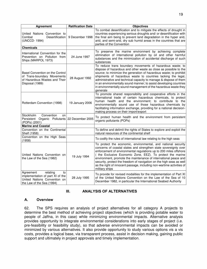
19
Agreement Ratification Date Objectives
United Nations Convention to Combat Desertification (UNCCD- 1994)
9 December 1998
To combat desertification and to mitigate the effects of drought in countries experiencing serious droughts and/ or desertification with the final aim being to prevent land degradation in the hyper arid, arid, and semi-arid, dry sub humid areas in the countries that are parties of the Convention
Chemicals
International Convention for the Prevention on Pollution from Ships (MARPOL 1973)
24 June 1997
To preserve the marine environment by achieving complete elimination of international pollution by oil and other harmful substances and the minimization of accidental discharge of such substances
Basel Convention on the Control of Trans-boundary Movements of Hazardous Wastes and Their Disposal (1989)
28 August 1992
To reduce trans boundary movements of hazardous waste; to dispose of hazardous and other waste as close as possible to the source; to minimize the generation of hazardous waste; to prohibit shipments of hazardous waste to countries lacking the legal, administrative and technical capacity to manage & dispose of them in an environmentally sound manner; to assist developing countries in environmentally sound management of the hazardous waste they generate
Rotterdam Convention (1998) 19 January 2006
To promote shared responsibility and cooperative efforts in the international trade of certain hazardous chemicals, to protect human health and the environment; to contribute to the environmentally sound use of those hazardous chemicals by facilitating information exchange, providing for a national decision-making process on their import/export
Stockholm Convention on Persistent Organic Pollutants (POPs) (2001)
22 December 2005 To protect human health and the environment from persistent organic pollutants (POPs)
Marine and Coastal Convention on the Continental Shelf (1958)
To define and delimit the rights of States to explore and exploit the natural resources of the continental shelf
Convention on the High Seas (1958)
To codify the rules of international law relating to the high seas
United Nations Convention on the Law of the Sea (1982)
19 July 1994
To protect the economic, environmental, and national security concerns of coastal states and strengthen state sovereignty over enforcement of environmental regulations up to 200 miles offshore ( the Exclusive Economic Zone, EEZ). To protect the marine environment, promote the maintenance of international peace and security, protect the freedom of navigation on the high seas as well as the right of innocent passage, including non-wartime activities of military ships
Agreement relating to implementation of part XI of the United Nations Convention on the Law of the Sea (1994)
28 July 1995 To provide for revised modalities for the implementation of Part XI of the United Nations Convention on the Law of the Sea of 10 December 1982, in particular the International Seabed Authority
III. ANALYSIS OF ALTERNATIVES
A. Overview
62. The SPS requires an analysis of project alternatives for all category A projects to determine the best method of achieving project objectives (which is providing potable water to people of Jaffna, in this case) while minimizing environmental impacts. Alternative analysis provides opportunity to integrate environmental considerations into early stages of project (i.e. pre-feasibility or feasibility study), so that adverse environmental impacts can be avoided or minimized by various alternatives. It also provide opportunity to study various options vis a vis costs, provides a logical base, via transparent process, assist in decision making, gaining public support and ultimately in project approvals and timely implementation.
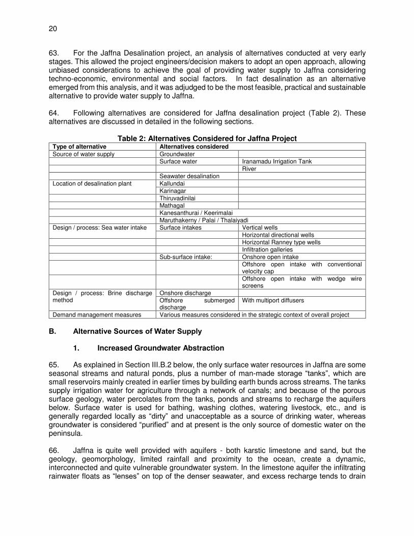
20
63. For the Jaffna Desalination project, an analysis of alternatives conducted at very early stages. This allowed the project engineers/decision makers to adopt an open approach, allowing unbiased considerations to achieve the goal of providing water supply to Jaffna considering techno-economic, environmental and social factors. In fact desalination as an alternative emerged from this analysis, and it was adjudged to be the most feasible, practical and sustainable alternative to provide water supply to Jaffna. 64. Following alternatives are considered for Jaffna desalination project (Table 2). These alternatives are discussed in detailed in the following sections.
Table 2: Alternatives Considered for Jaffna Project Type of alternative Alternatives considered
Source of water supply Groundwater Surface water Iranamadu Irrigation Tank River Seawater desalination Location of desalination plant Kallundai
Karinagar Thiruvadinilai Mathagal Kanesanthurai / Keerimalai Maruthakerny / Palai / Thalaiyadi Design / process: Sea water intake Surface intakes Vertical wells
Horizontal directional wells Horizontal Ranney type wells Infiltration galleries Sub-surface intake: Onshore open intake Offshore open intake with conventional
velocity cap Offshore open intake with wedge wire
screens Design / process: Brine discharge method
Onshore discharge Offshore submerged discharge
With multiport diffusers
Demand management measures Various measures considered in the strategic context of overall project B. Alternative Sources of Water Supply
1. Increased Groundwater Abstraction
65. As explained in Section III.B.2 below, the only surface water resources in Jaffna are some seasonal streams and natural ponds, plus a number of man-made storage “tanks”, which are small reservoirs mainly created in earlier times by building earth bunds across streams. The tanks supply irrigation water for agriculture through a network of canals; and because of the porous surface geology, water percolates from the tanks, ponds and streams to recharge the aquifers below. Surface water is used for bathing, washing clothes, watering livestock, etc., and is generally regarded locally as “dirty” and unacceptable as a source of drinking water, whereas groundwater is considered “purified” and at present is the only source of domestic water on the peninsula. 66. Jaffna is quite well provided with aquifers - both karstic limestone and sand, but the geology, geomorphology, limited rainfall and proximity to the ocean, create a dynamic, interconnected and quite vulnerable groundwater system. In the limestone aquifer the infiltrating rainwater floats as “lenses” on top of the denser seawater, and excess recharge tends to drain
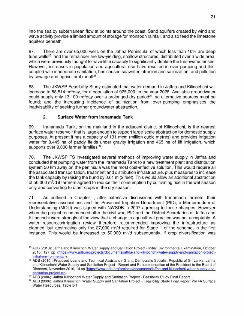
21
into the sea by subterranean flow at points around the coast. Sand aquifers created by wind and wave activity provide a limited amount of storage for monsoon rainfall, and also feed the limestone aquifers beneath. 67. There are over 65,000 wells on the Jaffna Peninsula, of which less than 10% are deep tube wells25, and the remainder are low-yielding, shallow structures, distributed over a wide area, which were previously thought to have little capacity to significantly deplete the freshwater lenses. However, increases in population and agricultural use have resulted in over-pumping and this, coupled with inadequate sanitation, has caused seawater intrusion and salinization, and pollution by sewage and agricultural runoff26. 68. The JKWSP Feasibility Study estimated that water demand in Jaffna and Kilinochchi will increase to 88,514 m3/day, for a population of 925,000, in the year 2028. Available groundwater could supply only 13,100 m3/day over a prolonged dry period27, so alternative sources must be found; and the increasing incidence of salinization from over-pumping emphasises the inadvisability of seeking further groundwater abstraction.
2. Surface Water from Iranamadu Tank
69. Iranamadu Tank, on the mainland in the adjacent district of Kilinochchi, is the nearest surface water reservoir that is large enough to support large-scale abstraction for domestic supply purposes. At present it has a capacity of 131 mcm (million cubic metres) and provides irrigation water for 8,445 ha of paddy fields under gravity irrigation and 465 ha of lift irrigation, which supports over 9,000 farmer families28. 70. The JKWSP FS investigated several methods of improving water supply in Jaffna and concluded that pumping water from the Iranamadu Tank to a new treatment plant and distribution system 50 km away on the peninsula was the most cost-effective solution. This would require all the associated transportation, treatment and distribution infrastructure, plus measures to increase the tank capacity by raising the bund by 0.61 m (2 feet). This would allow an additional abstraction of 50,000 m3/d if farmers agreed to reduce their consumption by cultivating rice in the wet season only and converting to other crops in the dry season. 71. As outlined in Chapter I, after extensive discussions with Iranamadu farmers, their representative associations and the Provincial Irrigation Department (PID), a Memorandum of Understanding (MOU) was signed with NWSDB in 2007 agreeing to these changes. However when the project recommenced after the civil war, PID and the District Secretaries of Jaffna and Kilinochchi were strongly of the view that a change in agricultural practice was not acceptable. A water resources/irrigation review therefore recommended improving the infrastructure as planned, but abstracting only the 27,000 m3/d required for Stage 1 of the scheme, in the first instance. This would be increased to 50,000 m3/d subsequently, if crop diversification was
25 ADB (2010): Jaffna and Kilinochchi Water Supply and Sanitation Project - Initial Environmental Examination, October
2010, 127 pp (https://www.adb.org/projects/documents/jaffna-and-kilinochchi-water-supply-and-sanitation-project-initial-environmental-)
26 ADB (2010): Proposed Loans and Technical Assistance Grant; Democratic Socialist Republic of Sri Lanka: Jaffna and Kilinochchi Water Supply and Sanitation Project - Report and Recommendation of the President to the Board of Directors, November 2010, 14 pp (https://www.adb.org/projects/documents/jaffna-and-kilinochchi-water-supply-and-sanitation-project-rrp)
27 ADB (2006): Jaffna Kilinochchi Water Supply and Sanitation Project - Feasibility Study Final Report 28 ADB (2006): Jaffna Kilinochchi Water Supply and Sanitation Project - Feasibility Study Final Report Vol 4A Surface
Water Resources, Table 5-1

22
successful and if a review of tank performance showed that an increase in capacity could be safely accommodated.29 72. The project was amended to incorporate this change; and elevated towers and distribution lines are currently under construction and contracts have been awarded for the treated water transmission main30. However further objections by farmers have prevented any work on the tank. The objections arose after the severe drought of 2012-13, which caused hardship in the agricultural community and exposed the risk of sharing the key resource with others. Farmers also wish to expand their dry-season cultivation rather than reduce it, to ensure their food security and household incomes in the face of heavy intergenerational land fragmentation31. 73. Abstraction of water from Iranamadu Tank to supply drinking water to Jaffna and the Kilinochchi communities in the vicinity of the tank remains a long-term objective of NWSDB. However obtaining agreement from all parties, especially the farmers and their associations, is by no means certain, and would require extensive and lengthy renegotiation. There is little prospect of agreement being reached in the near future, hence the need for NWSDB to seek alternative water sources.
3. The River for Jaffna Project
74. A scheme to convert some of the coastal lagoons around Jaffna into freshwater storage reservoirs (mainly for agricultural supply) was first proposed by the Irrigation Department in 1947. This involved construction of barrages and separation bunds across Vadamarachchi and Upparu lagoons (Figure 4) to prevent seawater ingress. This met with only partial success because of insufficient freshwater inflow and inadequate operation and management of the structures. Further work in the 1960’s attempted to capture drainage
Figure 4: The main proposals of the River for Jaffna Project (shown in yellow)
29 ADB 2010: Jaffna Water Supply Scheme - Assessment of Irrigation Component by PWC Dayaratne, 18 pp. 30 ADB 2016: Jaffna and Kilinochchi Water Supply and Sanitation Project - Project Data Sheet
(https://www.adb.org/projects/37378-013/main#project-pds) 31 ADB 2015: SRI (37378) Jaffna-Kilinochchi Water Supply and Sanitation Project Additional Financing: Social Due
Diligence Report, 26 December 2015, 10 pp.

23
from the mainland in Elephant Pass lagoon, and to convey this through a 4 km canal to flush the other two lagoons and augment freshwater storage. This scheme also suffered setbacks, including seawater ingress from the western end and a breach of the eastern bund by floodwaters from the catchment; and the scheme was abandoned before the “Mulliyan” link canal was completed28.
75. The Irrigation Department attempted to revive the project through further investigations in 1976, but this work was suspended because of the civil war. The only development since then has been the recent repair of two barrages, effected under government funding. The scheme therefore remains unproven, and with serious problems in design and construction, so it is unlikely that this would become a viable source of domestic water in the near future. It should also be noted that the environmental implications of this scheme may not have been adequately considered to date, as a project that involves the loss of large expanses of shallow coastal lagoons (which are important nursery grounds for a number of marine animals, including shrimps and fin-fish) is unlikely to comply with the safeguard policies of international lenders.
4. Water Management Measures
76. Feasibility study report of 2006 for proving water supply and sanitation in entire Jaffna Peninsula projected the total water demand as 88,500 m3/day for 2028 and 177,740 m3/day for 2058. Taking account of water resources and the design horizons, it proposed for implementation in the following 3 phases:
(i) Phase I: Potable water to Jaffna, Palai, Chavakachcheri and the Islands with a design horizon of 2028.
(ii) Phase II: Potable water to the remainder of the peninsula with a design horizon of 2028.
(iii) Phase III: To meet the demands of the whole project area for a design horizon of 2058.
77. The total demand of Phase 1 is estimated as 50,000 m3/day and is further divided into 2 stages to provide supply of 27,000 m3/day in stage 1 and 23,000 m3/day in stage 2. Currently phase 1 - stage 1 is under implementation to provide water supply of 27,000 m3/day, of which 24,000 m3/day is to be produced from desalination plant and the rest 3,000 is to be met by existing groundwater sources. This will be coupled with further measures including on-going efforts to revive support for the Iranamadu scheme, and other initiatives such as improved resource management, enhanced surface water storage, etc., to move towards the ultimate project objective of providing piped water to over a million people by 2058. 78. Besides supply augmentation measures, feasibility study also considered various demand management measures such as the following:
(i) Improved management of existing water resources, reducing losses and wastage, and improving quality by protecting wells from ingress of sewage and surface water runoff;
(ii) Large-scale organised expansion of water harvesting schemes to augment the supply from wells and enhance the recharge of aquifers.
79. These and other initiatives would have a role in the overall management of water resources and the protection and conservation of existing sources. These measures are essential to meet the growing demand, which are are to be implemented in conjunction with other supply augmentation measures.

24
80. Water management measures included in the overall project. Development of desalination plant along with potable water conveyance system, which is the subject of this EIA, is proposed for implementation under the larger context of providing water supply and sanitation is Jaffna and Killinochchi districts of Sri Lanka with the financial assistance of ADB. This project recognises32 that “addressing threats to water resources in Jaffna requires an integrated, cross-sectoral, and multidisciplinary institutional framework”. Lack of access to water; weak water resource coordination and planning and a lack of essential policies for managing water resources; and poor institutional capacity and inadequate awareness on water conservation, environmental protection, and hygiene among beneficiaries, have been identified as key development problems affecting water supply in Jaffna. Evolved on these premise, the Jaffna and Kilinochchi Water Supply and Sanitation Project (JKWSP), funded by ADB, is a key element in the Government of Sri Lanka’s (GoSL) strategy to reconstruct the north of the island after the end of the civil war in 2009. 81. Besides development of new sources of water supply, the project lays equal emphasis on demand management to cut water losses, provide monitoring, and improve overall efficiency. One of the outcomes of the project is: improved protection and management of Jaffna Peninsula's water resources. The outputs of the project which aimed at demand management include: rehabilitating and improving infrastructure to improve efficiency levels; water connections and community water facilities with meters to measure water usage; replacing existing old and leaking distribution systems, installing bulk/system water meters to monitor flows; and instituting a leak detection program for the existing distribution network. Another output specifically aims at the institutional aspect to strengthen the water resource management in Jaffna, which also include conducting public water conservation, environmental protection, and hygiene awareness campaigns, and a program for community monitoring.
5. Seawater using Desalination Process
82. Though the FS also considered seawater desalination as a supply option on offshore islands where there are severe constraints on the quality and quantity of available groundwater, it was rejected initially because of the high cost of supplying comparatively few inhabitants. Subsequently, a water balance study conducted by JKWSP in 2013 found that abstraction from the Iranamadu tank as initially proposed could result in a supply failure on 27 days per year, causing water shortages for both farmers and domestic consumers. NWSDB therefore investigated other potential sources and technologies, including additional groundwater abstraction on Jaffna Peninsula, and development of a new surface water reservoir downstream of the Iranamadu tank command area33. It was also decided to re-examine seawater desalination in the context of supplying a much larger consumer base, on the Jaffna mainland. 83. With support from ADB, NWSDB commissioned a review of all relevant previous studies, to provide a rapid assessment of the feasibility of sea water desalination and other alternative water sources to provide safe drinking water for the Jaffna Peninsula. This concluded that seawater desalination is the only option that will provide high quality drinking water independent of climatic conditions (i.e. would not be affected by drought). 84. ADB/NWSDB then commissioned a study of the feasibility of constructing a 24 MLD (24,000 m3/d) seawater reverse osmosis desalination plant (RODP) on the Jaffna Peninsula. This
32 ADB (2010). Project Administration Manual. Democratic Socialist Republic of Sri Lanka: Jaffna & Killinochchi Water
Supply & Sanitation Project. 33 Command area is the area that can be cultivated under an irrigation scheme
25
was conducted in 2014-15 and included development of conceptual designs and cost estimates. The study concluded that such a project is feasible, so seawater reverse osmosis membrane desalination was chosen as the technology to supply 300,000 consumers, approximately half of the current population. This will be combined with other initiatives, including improved resource management and rainwater harvesting as discussed above, and increasing the capacity of Iranamadu tank in combination with on-going efforts to obtain farmers’ agreement to share water at the revised lower rate (27,000 m3/d), in order to supply the entire population of Jaffna in due course. 85. Selection of Desalination Process. Various types of desalination processes are at present available to produce potable water from the sea water. Depending on the principle process involved these are mainly of three types:
(i) Thermal processes in which natural system of evaporation and condensation is replicated to separate salts from water. Available technologies include multi-stage flash distillation (MSF), multiple-effect distillation (MED), vapor compression distillation (MVC), humidification - dehumidification desalination (HDH) and solar distillation.
(ii) Membrane pressure systems, in which salty water is passed through a membrane under pressure to separate salts and water. These technologies include reverse osmosis, electrodialysis and nanofiltration.
(iii) Chemically-activated desalination methods. These technologies include ion-exchange desalination and liquid–liquid extraction.
86. Based on the following factors reverse osmosis (popularly known as RO) desalination, which is a membrane pressure system, is adopted for desalination project in Jaffna. In this a reverse osmosis membrane is used to demineralize or deionize water (in this case sea water). RO membrane is a semi-permeable membrane that do not allow the majority of dissolved salts, organics, bacteria etc., contained in the water to pass through. Pressure applied on water to pass through is greater than the naturally occurring osmotic pressure in order to separate salts and water from sea water.
(i) RO is the most energy efficient of all the desalination technologies that are commercially available; it uses the least amount of energy for the water produced in this region
(ii) RO uses a technology that is readily adapted to the ambient conditions in Jaffna (iii) It uses a technology the knowledge of which can be readily transferred over time
to officers of the NWSDB (iv) It is a mature technology and is well understood (v) It is the technology of choice in most parts of the world (70% of plants use RO)
(alternative (thermal) technologies are used in the middle east where energy is in ample and cheap supply)
(vi) It is the technology that attracts the lion’s share of research and development funds and as such is the technology that will continue to improve
(vii) It is the technology that will attract the most number of competitive bids as it is the one known to all the major desalination plant providers
C. Alternative Project Locations for Desalination Plant
87. The RODP Feasibility Study considered six alternative sites as potential locations of the plant (see Figure 5), which were chosen after field inspections and discussions between the FS consultant, Project Engineering and Institutional Consultant, local experts from NWSDB and public utility officials. Sites were evaluated on the basis of 12 key factors as follows:

26
(i) seawater quality, especially parameters that influence desalination plant operation costs (salinity, temperature, turbidity, algal content, etc.);
(ii) presence of environmentally sensitive habitats (e.g. coral and sea grass) at the intake and outfall locations;
(iii) potential impacts of intake and outfall construction and operation on marine flora and fauna;
(iv) proximity to fishing villages and fishing grounds, which may be affected during construction and operation with adverse socio-economic consequences;
(v) beach condition and erosion (which could affect structural integrity of intakes); (vi) site elevation and potential for flooding and impact from tsunamis; (vii) beach/near shore topography and its suitability for installation of pipelines; (viii) presence of near shore currents and naturally occurring mixing, which could
accelerate dilution and dispersion of desalination plant effluent; (ix) adequate depth (>5 m) for installation of an intake with features to minimise
entrainment of marine animals, algae and contaminated surface water; (x) proximity to a suitable high-voltage supply; (xi) distance to the drinking water distribution system; (xii) potential impacts on local traffic, households, agricultural and fishing activities and
existing drinking water wells.

27
Figure 5: Potential project sites evaluated by the Feasibility Study

28
88. Table 3 summarises the evaluation of each location, which shows that Sites 5 (Kankesanthurai/Keerimalai) and 6 (Maruthankerny/Pallai / Thalaiyadi) are clearly the most suitable, as they are not known to be environmentally sensitive, and have lower salinities than the other sites (because freshwater aquifers drain into the sea nearby), which would reduce costs for desalination equipment and require less energy for freshwater separation. There are several other advantages, including: no visible marine life in the near shore area; relatively deep water within 1 km of the beach; close to high voltage power supply; no fishing grounds or drinking water wells in the vicinity; relatively high site elevation and adequate distance from zones of active beach erosion; and sparsely populated with little agricultural activity nearby.
Table 3: Evaluation of alternative project sites by RODP Feasibility Study (ADB 2015)
No Location Suitability for RODP development
1 Kalluandai The least suitable site in terms of water quality and impact on marine life; and close to a landfill and cemetery, which are potential sources of pollution and inappropriate locations for industrial development
2 Karainagar An environmentally sensitive site because of the presence of sea grass beds and coral outcrops; also a long distance from a high voltage power connection, which could make the project costly and unfeasible
3 Thiruvalinilai Another sensitive site, with coral and sea grass close to the shore. High salinity, so not ideal as source water; and a shallow seabed, where 5 m depth is more than 2 km from the shore, so pipeline development would be costly
4 Mathagal Similar to Site 3 with coral and sea grass in the inshore area and deeper water over 2 km from the beach, so unsuitable in terms of environmental impacts and construction costs
5 Kankesanthurai/
Keerimalai
Relatively low salinity, which will reduce construction and operation costs. However the location is in a government high security zone and near religious sites, which may preclude land acquisition and industrial development
6 Maruthankerny/
Pallai / Thalaiyadi
Probably the most suitable location as it is not known to be environmentally sensitive and has the lowest salinity and the shortest intake distance, and a power connection close to the site. Beach erosion may require the site to be located farther inland (0.5 km from the beach) than other sites (0.2 to 0.3 km)
89. These two sites were evaluated further in the FS report and Maruthankerny/Pallai/ Thalaiyadi was recommended for the following reasons:
(i) Likely lower socio-economic impacts (sparsely populated, limited agriculture and no shrines, temples or other artefacts of religious or historical importance);
(ii) Lower environmental impacts because sea conditions will promote mixing and effluent dispersion in an area with no obviously sensitive marine habitats;
(iii) Favourable seabed profile and depth, which will facilitate intake and outfall construction;
(iv) Lower cost because of easier/closer connection to the power grid and water distribution system.
90. Coastal & Marine Environment in Northern Province. The coastal and marine environment in the Northern Province contains a large proportion of the coastal ecosystems; mangroves, coral reefs, sea grass beds and brackish water lagoons and salt marshes. In addition there are lagoons, inland water bodies and streams. Shallow coastal waters around Sri Lanka has an estimated 680 km2 of coral reefs; most of these shallow coral habitats are located in the Gulf of Mannar and along the east coast in the Trincomalee and Batticaloa Districts. In addition fringing coral reefs occur in the northern and southern areas of the island. Coral reefs of the Jaffna
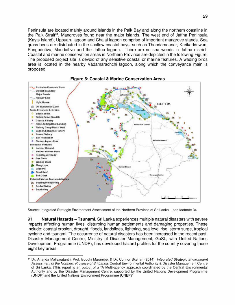
29
Peninsula are located mainly around islands in the Palk Bay and along the northern coastline in the Palk Strait34. Mangroves found near the major islands. The west end of Jaffna Peninsula (Kayts Island), Uppuaru lagoon and Chalai lagoon comprise of important mangrove stands. Sea grass beds are distributed in the shallow coastal bays, such as Thondamaanar, Kurikadduwan, Pungudutivu, Mandaitivu and the Jaffna lagoon. There are no sea weeds in Jaffna district. Coastal and marine conservation areas in Northern Province are depicted in the following Figure. The proposed project site is devoid of any sensitive coastal or marine features. A wading birds area is located in the nearby Vadamarachchi lagoon, along which the conveyance main is proposed.
Figure 6: Coastal & Marine Conservation Areas
Source: Integrated Strategic Environment Assessment of the Northern Province of Sri Lanka – see footnote 34 91. Natural Hazards – Tsunami. Sri Lanka experiences multiple natural disasters with severe impacts affecting human lives, disturbing human settlements and damaging properties. These include: coastal erosion, drought, floods, landslides, lightning, sea level rise, storm surge, tropical cyclone and tsunami. The occurrence of natural disasters has been increased in the recent past. Disaster Management Centre, Ministry of Disaster Management, GoSL, with United Nations Development Programme (UNDP), has developed hazard profiles for the country covering these eight key areas.
34 Dr. Ananda Mallawatantri, Prof. Buddhi Marambe, & Dr. Connor Skehan (2014). Integrated Strategic Environment
Assessment of the Northern Province of Sri Lanka. Central Environmental Authority & Disaster Management Centre of Sri Lanka. (This report is an output of a “A Multi-agency approach coordinated by the Central Environmental Authority and by the Disaster Management Centre, supported by the United Nations Development Programme (UNDP) and the United Nations Environment Programme (UNEP)”
RODP Site
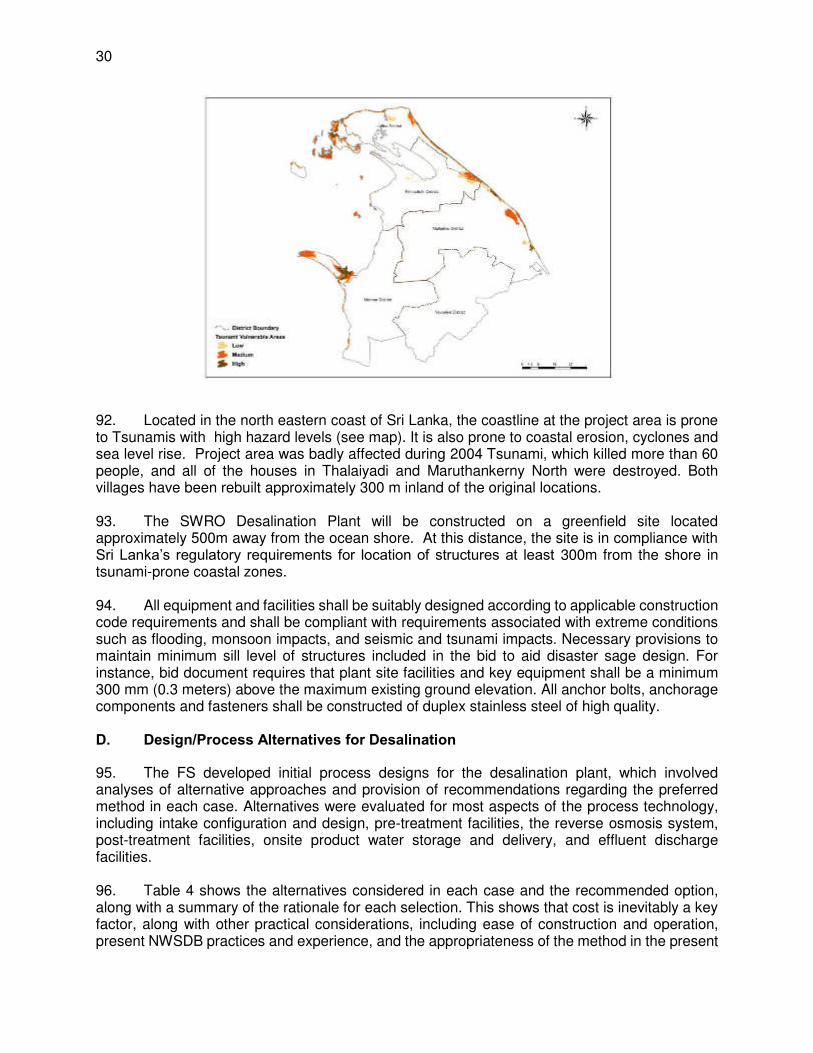
30
92. Located in the north eastern coast of Sri Lanka, the coastline at the project area is prone to Tsunamis with high hazard levels (see map). It is also prone to coastal erosion, cyclones and sea level rise. Project area was badly affected during 2004 Tsunami, which killed more than 60 people, and all of the houses in Thalaiyadi and Maruthankerny North were destroyed. Both villages have been rebuilt approximately 300 m inland of the original locations. 93. The SWRO Desalination Plant will be constructed on a greenfield site located approximately 500m away from the ocean shore. At this distance, the site is in compliance with Sri Lanka’s regulatory requirements for location of structures at least 300m from the shore in tsunami-prone coastal zones. 94. All equipment and facilities shall be suitably designed according to applicable construction code requirements and shall be compliant with requirements associated with extreme conditions such as flooding, monsoon impacts, and seismic and tsunami impacts. Necessary provisions to maintain minimum sill level of structures included in the bid to aid disaster sage design. For instance, bid document requires that plant site facilities and key equipment shall be a minimum 300 mm (0.3 meters) above the maximum existing ground elevation. All anchor bolts, anchorage components and fasteners shall be constructed of duplex stainless steel of high quality. D. Design/Process Alternatives for Desalination
95. The FS developed initial process designs for the desalination plant, which involved analyses of alternative approaches and provision of recommendations regarding the preferred method in each case. Alternatives were evaluated for most aspects of the process technology, including intake configuration and design, pre-treatment facilities, the reverse osmosis system, post-treatment facilities, onsite product water storage and delivery, and effluent discharge facilities. 96. Table 4 shows the alternatives considered in each case and the recommended option, along with a summary of the rationale for each selection. This shows that cost is inevitably a key factor, along with other practical considerations, including ease of construction and operation, present NWSDB practices and experience, and the appropriateness of the method in the present

31
site conditions. However certain key decisions were made on the basis of environmental considerations, and it is worth noting that these were the factors with the greatest potential to cause environmental impacts, namely the approach and design of the seawater intake and the effluent discharge outfall.
Table 4: Evaluation of design/process alternatives by RODP Feasibility Study
RODP Element Alternatives Evaluation Summary
Saline groundwater intake
Vertical wells Impractical: requires 66-80 wells in >4km of seashore Horizontal Directionally Drilled (HDD) wells
Highly complex and impractical, requiring 12-14 HDD wells
Horizontal Ranney-type wells
Impractical and high cost: 6-8 wells in >3 km of beach
Infiltration galleries Costly; ecological damage: excavation of >1 ha of seabed Open seawater intake Onshore intake (canal) Not viable: high visual impact, delivers inferior quality water
Offshore open intake (tower)
Recommended: Most common type; needs 6-8 m depth
Offshore intake with wedge wire screens
Current velocity may not be enough for constant operation
Intake structure and piping
Single inlet and pipe Recommended: less costly and quicker construction
Multiple inlet units More costly but higher reliability and reduced downtime Intake pipe material High-density Poly-ethylene
(HDPE) Recommended: most widely-used, durable, resistant to corrosion, easy to transport and install
Steel More durable, can withstand higher storm, current and wave forces, but construction costs are 20-30% higher
Type of screens Band screens Recommended: 30-40% cheaper, suitable for this site Drum screens Generally used where debris in source water fluctuates widely
Intake pump station Wet well, vertical turbine pumps
Recommended: more energy efficient, easier maintenance, more reliable, low cost
Dry pit, horizontal centrifugal pumps
Require less maintenance, but greater construction costs and risk of outage due to flooding
Canned vertical turbine pump
Small footprint, lowest construction cost
Pre-treatment facility Single stage pre-treatment Used if source water is low in turbidity and algal content
Two stage pre-treatment Recommended: shallow intake area where turbidity is above threshold levels
Pre-treatment filtration - 1st stage
Dissolved air flotation (DAF)
Removes floating particulates (algal cells, oil and grease, etc.) that cannot be captured by other methods
Gravity granular media filters
Recommended if source water is suitable (to be confirmed). Widely used, low cost, removes larger particles and algae
Pre-treatment filtration - 2nd stage
Gravity granular media filters
Not appropriate if already used in 1st stage
Pressure granular media filters
Recommended: Lowest total cost when combined with 1st stage gravity. Removes fine silt and other small particles
Membrane filters Require upstream micro screens to remove shell fragments, plankton and other fine debris that can damage membranes
RO Membrane trains (racks)
Single pass (once-through) Recommended: lowest cost, suitable for site source water
Two pass Most costly; used for enhanced boron removal; requires addition of antiscalant
Partial two pass Recommended if NWSDB require two-pass; cheaper than full two-pass system
RO energy recovery devices (ERD)
Pelton wheel Simple, compact , energy efficient, relatively low cost Turbocharger Simple, low cost, but less efficient in large applications
Francis turbine Achieves maximum efficiency only in a narrow range of flow conditions. No longer widely used
Pressure exchanger Recommended: reliable, high energy recovery; most widely used ERD in medium/large RODPs worldwide
Dual work exchanger More complex than pressure exchangers; more maintenance Lime and Carbon Dioxide Recommended: Widely used worldwide, including Sri Lanka

32
RODP Element Alternatives Evaluation Summary
Post-treatment re-mineralisation
Limestone (calcite) contactors
Less costly, produce lower turbidity finished water; but it is not known whether high-grade limestone is available in Sri Lanka
Post-treatment disinfection Chlorine gas
Cheap, widely used, but safety risks (accidental gas release); , already used at NWSDB plants in Sri Lanka; Recommended with proper safety measures
Calcium hypochlorite Safer to use, handle and store Onsite product water storage
Steel tanks Easier and less expensive to build; but more costly to maintain Concrete tanks Recommended: longer life (50-100 years) than steel (25-30y) Buried tanks No visual impact; simpler construction if pump station is above Above-ground tanks Recommended: 20-30% cheaper than buried; easy to access Rectangular tanks Easier construction, 10-20% cheaper; but more prone to leaks Circular tanks Recommended: durable; most common for large volumes
Product pump station pumps
Vertical turbine centrifugal Less costly; more efficient; smaller pump station Horizontal split-case Recommended: Easier to maintain; used at NWSDB plants
Discharge outfall Onshore (beach) discharge
Simple construction; 15-20% cheaper to build; but requires rapid near shore currents to dissipate saline discharge
Offshore outfall with diffusers
Recommended: necessary to disperse effluent effectively at this site
1. Sea Water Intake Alternatives
97. The purpose of the source (sea) water intake facilities is to deliver the needed volume of water for the desalination plant operations continuously and reliably. The configuration of the water intake facilities will depend on the selected desalination plant configuration. There are two main categories of intake for desalination plants: surface (open) and subsurface (ground water) intakes. Both types of intakes are evaluated for the site specific conditions. 98. Subsurface intakes are buried pipes and/or wells dug beneath the shoreline or ocean floor. Seawater is drawn through the subsurface into the intake pipe. Source water is filtered through the aquifer soils and as a result it typically has relatively low particulate content and high water quality. The most common types of subsurface intakes for desalination plants are: (i) vertical wells; (ii) horizontal directionally drilled (HDD) wells; (iii) horizontal Ranney-type wells; (iv) infiltration galleries. Vertical wells are most widely used for seawater desalination facilities. The subsurface intake facilities are relatively simple to build and the saline water they collect is pre-treated via slow filtration through the subsurface soil formations in the area of source water extraction. Therefore, raw water collected using subsurface intakes is usually of better as compared to open intakes. The natural seabed filtration process removes practically all coarse solids and particulates of a size of 50 μm or larger from the seawater and precludes marine organisms in all phases of development (adults, juveniles and larvae) from entering the desalination plant (i.e., protects marine life against impingement and entrainment). This system is also an effective barrier against the heavy solid loads generated during algal blooms and oil spills. 99. Surface intakes collect water directly from the open sea, and are located above the sea floor. These are most common type of intakes for large desalination plants. These include a intake pipe with concrete collars that include trash racks and screens to remove debris and particulate matter (both organic and inorganic), respectively. Surface intakes require addition of a pre-treatment system prior to the desalination process to remove marine life and small particles in the feed water. The two general types of open intakes are considered for this project: onshore intake and offshore intake. 100. Open intakes are the most widely applied type of source water collection facility for plants of size comparable to that of the Jaffna desalination plant. Subsurface intakes are not practical
33
for large desalination plants because of their complexity and challenges associated with finding uniform coastal aquifers that could consistently produce the large volumes of source waters needed for the desalination facility. At present there are less than dozen SWRO plants worldwide of comparable size which have subsurface intakes. Based on the site data, the coastal aquifer conditions at the site are not favourable for construction of large subsurface intake because the high-permeability limestone formations near shore are very shallow (10 to 30 m). Such shallow aquifer will allow to build wells with yield of only 100 to 500 m³/day, which will result in an excessively large number of wells along the shoreline. While such wells will produce water of better source water quality in terms of algal content and turbidity, because of the relatively close vicinity of the plant site to agricultural and residential areas, such intakes will yield water of variable water quality and the source water will likely contain elevated concentrations of iron and manganese, which will require elaborate and costly pre-treatment. Well useful life is uncertain because of the relatively high potential for beach erosion. Therefore, open intake is selected as is the most viable type of source water collection facility for the Jaffna desalination project. 101. Two alternatives are further evaluated in offshore open intakes: (i) conventional velocity cap type intake, and (ii) wedge wire screen intake.
(i) Velocity cap is applied only to off-shore-submerged intakes, which essentially reduces the velocity and also changes the direction of water flow from vertical to horizontal flow into the intake. It distributes the flow over a large around the intake, so that flow velocities are reduced to speeds avoidable by many fish. Fish are more sensitive to horizontal rather than vertical flow and will generally more readily avoid horizontal changes in velocity. This type of intake will also consists of a coarse screen and fine screen. Available literature indicate that “the use of a velocity cap on a submerged off-shore vertical riser intake significantly reduces the entrapment and impingement of many forms of pelagic marine life including fish, invertebrates and wildlife such as turtles.”
(ii) Wedge wire Screens are passive (stationary) screening equipment located off-shore, which is directly connected to the suction end of the intake pump station thereby eliminating the need for additional coarse or fine screening facilities. Wedge wire screens typically have 3 mm openings, located at 3 m above the sea bottom, and sufficiently below the sea surface. Wedge wire screen intakes combine very fine mesh size with low water velocity by extending over a very large area relative to the flow rate. Even with very low approach velocities this system will eventually clog if not periodically cleaned. Periodic bursts of compressed air are used to dislodge debris from its openings. Naturally occurring water currents carry the dislodged material away. Therefore, having consistent currents in selected marine site is a requirement for efficient operation.
102. Considering all the above pros and cons, based on the site specific conditions, off-shore velocity cap type conventional intake is considered for the proposed RODP at Jaffna. Details of alternatives studied are presented in the below table.
Table 5: Evaluation of RODP Intake Alternatives Description Details Feasibility study recommendations
1 Subsurface Intakes
Vertical wells Most commonly used type of subsurface intakes
Key components: casting, well screen, filter pack, well seal, a surface seal, and a submersible or vertical turbine pump installed inside the well casting
Based on the soil conditions along the shore, vertical wells are not considered practical. Large number of individual wells need to be constructed (66 to 80 wells) and large

34
Description Details Feasibility study recommendations
Well diameter 200 – 1200 mm; depth ~75 m shoreline area required to install these wells (over 4 km of seashore).
Horizontal directional drilling (HDD) wells
The HDD collector wells consist of relatively shallow blank well casting with one or more horizontal perforated screens bored under an angle (typically 15 to 20 degrees) and extending from the surface entry point underground past the mean-tide line.
Source water is collected via a number of perforated HDPE pipes with 120-μm pores, at a slow rate, naturally filtered through the ocean bottom sediments. Typical collector pipe size is 450 mm. individual HDD collector pipes deliver the source water into a common wet well
SWRO Plant is projected to require the construction of 12 to 14 HDD wells, which makes such system very complex and impractical for the site-specific conditions of the Jaffna project.
Horizontal Ranney type intake wells
This type of wells consists of a concrete caisson that extends below the ground surface with water well collector screens (laterals) projected out horizontally from inside the caisson into the surrounding aquifer. Since the well screens in the collector wells are placed horizontally, higher rate of source water collection is possible than with most vertical wells.
Caisson of the horizontal collector well is typically 3 - 7 m diameter, 10 - 45 m depth varies according to geologic conditions
Number laterals varies (2-14); diameter from 0.2 - 0.3 m and length extends up to 60 m
While horizontal Ranney wells would allow to collect relatively large volumes of water, the very high number of such types of wells (6 to 8) and large strip of beach which will be occupied by them (more than 3 km) makes this type of intake impractical at Jaffna site
Infiltration galleries
Consist of a submerged slow sand media filtration bed located at sea bed. The bottom of this engineered filtration bed contains horizontal perforated pipes to convey to wet well of intake well & pump house located on the shore
Infiltration galleries are typically implemented when conventional horizontal or vertical intake wells cannot be used due to unfavourable hydrogeological conditions.
Use of seabed infiltration system will require the excavation of over 1 ha of ocean bottom, which will be very costly and will result in significant damage of the benthic flora and fauna. Therefore it is found to be unfeasible for the Jaffna SWRO project.
2. Surface intakes
Onshore open intake
Typically consists of large & deep intake canal ending into a concrete forebay structure equipped with coarse bar screens followed by fine screens and intake pump station
One significant disadvantage is that they typically deliver comparatively inferior source water quality
Will have a significantly higher visual and environmental impact on the coastal environment..
Offshore intake – Conventional velocity cap type open intake
Typically consist of: velocity-cap type inlet structure, one or more intake water conduits (pipelines or intake tunnel); on-shore intake chamber; trash racks; fine screens; and source water intake pump station.
The inlet structure is usually a vertical well located 4 to 10 meters above the sea floor &
submerged between 4 and 20 m below the water surface.
Velocity cap limits the entry water velocity into the suction pipe, thus significantly minimizing the infringement and entrapment.
Open intakes are the most commonly used intake for medium and large desalination plants.
Selected.

35
Description Details Feasibility study recommendations
Offshore intake – Wedge wire screens
These are conventional open offshore intakes as explained above, except that these are provided with wedge wire screens
Wedge wire Screens are passive (stationary, no moving mechanical part) screening equipment located off-shore, which is directly connected to the suction end of the intake pump station thereby eliminating the need for additional coarse or fine screening facilities.
Wedge wire screens have 3 mm openings; typically located at 3 m above the sea bottom; made of copper-nickel alloy screen flow-through velocity is 0.15 m/sec
Combines very low flow-through velocities small slot size, and naturally occurring high screen surface sweeping velocities to minimize impingement and entrainment.
Includes an air burst back-flush system to blow-off debris back into the sea
considered by USEPA as Best Technology Available for impingement and entrainment reduction.
Adequate depth of water column is required for provide wed wire screens. Reaching depths of 12 to 20 m is required at this site, which would require extending the intake to a minimum of 2,000 m. It is estimated that intake length over 1,500 m at this site will be very expensive. Therefore wedge wire screen is not considered feasible
103. Considering all the above pros and cons, based on the site specific conditions, and the following techno-economic reasons, an off-shore velocity cap type conventional intake is considered for the proposed RODP at Jaffna:
(i) It is the most applicable means of extract seawater given the small size of the plant (ii) It is the technology best suited to the topography and geotechnical conditions
experienced in Jaffna (iii) It is the most cost effective technology to use for this site (iv) It is the most commonly used technology for this purpose (v) It is a technology that has low maintenance costs (vi) It is a technology that has a high degree of reliability (and little that can go wrong)
which is useful for this first-in-country plant
2. Alternative Brine Discharge Methods
104. Brine Characteristics. Desalination process principally generates permeate (product) and a concentrated effluent (waste stream) called brine, which is nearly twice as saline as raw sea water intake of the plant. In addition to concentrate, desalination plant discharges may also include other treatment process side-streams, such as spent pre-treatment filter backwash water, SWRO membrane rinsing water, and treated membrane cleaning water. Besides the desalination concentrate also consists of dissolved solids, if present in the feed water, which are rejected by the RO membranes. Concentrate from seawater desalination plants using open ocean intakes typically has the same colour, door, oxygen content and transparency as the source seawater from which the concentrate was produced. Therefore, concentrate discharged to ocean does not typically change its physical characteristics or aesthetic impact on the aquatic environment, except for its density. 105. Salinity, Density & Temperature. The ambient sea water salinity at the intake point is 32 ppt (32,000 mg/l) and at 45%-50% recovery rate, the salinity of brine will be in the range of 58 to 64 ppt (58,000 to 64,000 mg/l). The density of the brine will be higher than the sea water due to higher concentration of salinity. Density of brine will be in the range of 1,040 – 1,045 kg/m3,

36
higher than the ambient density of 1021 kg/m3 at the intake site. As the RO process do not involve any thermal or chemical processes that affect the temperature, brine will remain at the same temperature as the ambient sea water temperature (around 25oC). 106. Dissolved compounds. Desalination concentrate consists of dissolved compounds (minerals, organics, metals, etc.) rejected by the reverse osmosis membranes. A comprehensive water quality analysis of feed water (seawater at intake point of RODP) was carried out and a very wide range of determinants were analysed, 74 in total, including all of the standard physical and chemical parameters, plus 12 heavy metals and 35 pesticide residues. The results indicate that seawater quality at the project site is good, with low values of suspended solids (< 2 mg/l) and organic matter (< 5 mg/l 5-day BOD), and no evidence of pollution by oil and grease, heavy metals, faecal bacteria or pesticides. Over 80% of the feed water salinity is due to chlorides, sodium and magnesium, which are not food sources or nutrients for aquatic organisms. Given the good sea water quality devoid of any pollutants of anthropogenic origin, the dissolved compounds that are rejected by RO membranes and that ultimately find its way into the brine concentrate, are also not of anthropogenic origin. Therefore, the composition and concentration of dissolved substances in the brine is not of cause of concern. 107. RO Treatment waste stream. Filter back wash water, membrane cleaning / rinsing water, and traces of other chemicals used in these processing including the pre-treatment post treatment finds its way into waste stream, and needs to be disposed safely. These include antifouling, biocides, antiscalants, coagulants, antifoaming agents, and cleaning chemicals. Sodium hypochlorite is to be used for disinfection and the control of biological growth throughout the plant. Chlorine gas is to be used for disinfecting the potable water. Following table shows the chemicals used in the treatment process. The waste streams form the cleaning processes pass through a neutralisation tank, where the chemicals are reduced to salts in ionic form, and will join the concrete stream (brine) for disposal into sea via the outfall. The filter backwash water is processed at the desalination plant site by settling, and therefore will reduce total suspended solids and BOD concentration. The organics and solids removed from the source seawater are disposed to a landfill as solid residuals. Various wastes will be generated by the plant, and each of these waste streams will be managed according to its phase and composition. The bid/contract requires that all waste from the plant be disposed of according to the Sri Lankan regulations and permits. The contractor is required to monitor and report on the management of waste. However, the type of pre-treatment is not known at this stage, and it is difficult to predict what is might be. If chlorine is used to control bio growth in intake pipe and in plant, which may enter the brine. Bid/contract requires that the brine discharge shall meet the specified limits for residual chlorine, which is 0.2 mg/l, which is stringent than CEA regulation f 1 mg/l. Given very low concentrations and traces of the chemicals in the brine, it is unlikely to cause any notable changes in the receiving water body.
Table 6: Chemicals used in the RO treatment process
Chemical Dosing points Units Average Endpoint
Antiscalant 1P RO 1st pass for control of alkaline & non alkaline scale
mg/L 0.2-0.5 Brine
Citric Acid RO cleaning chemical kg/clean Note 5 Brine Sodium Lauryl Sulphate (Detergent) RO cleaning chemical kg/clean Note 5 Brine
Sodium Bisulphite RO 1st pass (except during shock chlorination)
mg/L <51 Brine
Sulphuric Acid Pre-treatment prior to granular media filters
mg/L 10-202 Brine
Sodium Hypochlorite Pre-treatment (shock chlorination) mg/L 3 Brine
Ferric Chloride Pre-treatment prior to granular media filters
mg/L 3-102 Landfill (solids)
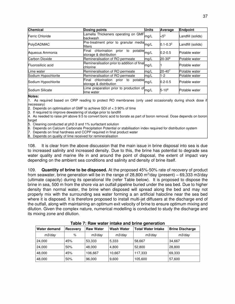
37
Chemical Dosing points Units Average Endpoint
Ferric Chloride Lamella Thickeners operating on GMF backwash
mg/L <53 Landfill (solids)
PolyDADMAC Pre-treatment prior to granular media filters
mg/L 0.1-0.32 Landfill (solids)
Aqueous Ammonia Final chlorination prior to potable storage & distribution
mg/L 0.2-0.5 Potable water
Carbon Dioxide Remineralisation of RO permeate mg/L 20-306 Potable water
Fluorosilicic acid Remineralisation prior to addition of final chlorine
mg/L 1 Potable water
Lime water Remineralisation of RO permeate mg/L 20-407 Potable water Sodium Hypochlorite Remineralisation of RO permeate mg/L 1-2 Potable water
Sodium Hypochlorite Final chlorination prior to potable storage & distribution
mg/L 0.2-0.5 Potable water
Sodium Silicate Lime preparation prior to production of lime water
mg/L 5-108 Potable water
Notes: 1. As required based on ORP reading to protect RO membranes (only used occasionally during shock dose if necessary) 2. Depends on optimisation of GMF to achieve SDI of < 3 90% of time 3. If required to improve dewatering of sludge prior to landfill 4. As needed to raise pH above 9.5 to convert boric acid to borate as part of boron removal. Dose depends on boron target 5. Cleaning conducted at ph2-3 and 1% surfactant solution 6. Depends on Calcium Carbonate Precipitation Potential or stabilisation index required for distribution system 7. Depends on final hardness and CCPP required in final product water 8. Depends on quality of lime received for remineralisation
108. It is clear from the above discussion that the main issue in brine disposal into sea is due to increased salinity and increased density. Due to this, the brine has potential to degrade sea water quality and marine life in and around the point of disposal, the extent of impact vary depending on the ambient sea conditions and salinity and density of brine itself. 109. Quantity of brine to be disposed. At the proposed 45%-50% rate of recovery of product from seawater, brine generation will be in the range of 28,800 m3/day (present) – 69,333 m3/day (ultimate capacity) during its operational life (refer Table below). It is proposed to dispose the brine in sea, 500 m from the shore via an outfall pipeline buried under the sea bed. Due to higher density than normal water, the brine when disposed will spread along the bed and may not properly mix with the surrounding sea water forming a an artificial halocline near the sea bed where it is disposed. It is therefore proposed to install multi-jet diffusers at the discharge end of the outfall, along with maintaining an optimum exit velocity of brine to ensure optimum mixing and dilution. Given the complex nature, numerical modelling is conducted to study the discharge and its mixing zone and dilution.
Table 7: Raw water intake and brine generation Water demand Recovery Raw Water Wash Water Total Water Intake Brine Discharge
m3/day % m3/day m3/day m3/day m3/day
24,000 45% 53,333 5,333 58,667 34,667
24,000 50% 48,000 4,800 52,800 28,800
48,000 45% 106,667 10,667 117,333 69,333
48,000 50% 96,000 9,600 105,600 57,600

38
110. Alternative Brine Discharge Methods. Two methods considered: Onshore (open surface) discharge and offshore (submerged) outfall discharge (buried pipeline with exposed diffusers at the discharge end). 111. Onshore discharge include a discharge structure on the shore that will dispose the blended discharge of desalination plant concentrate and other waste streams directly on the ocean shore. Their key advantages are 15 to 30% lower construction costs than offshore discharges and simple construction and monitoring. However, since the brine discharge is negatively buoyant, if it is released as a surface flow, the discharge will flow along the sea bed forming density current. Therefore the impact to the sea bed can be considerable, which will nevertheless depend on the sensitivity of the sea bed at such location. Also, a critical factor for the feasibility of onshore discharge is the presence of near-shore current that would quickly dissipate the saline discharge plume. The hydrodynamic conditions of the selected site at Thalaiyadi indicate that near-shore conditions do not favour such discharge.
.
112. Offshore submerged discharge. Brine is negative buoyant in nature, and it is important to release the discharge as a jet flow instead of releasing it as a surface flow to avoid density current on the sea bed (as discussed above), and the offshore submerged outfall discharge pipeline will provide that advantage. The concentration of a pollutant after discharge depends on the initial discharge concentration, the concentration in the ocean and the level of dilution. The alternative plant discharge disposal method for Jaffna project considered is an “offshore outfall with diffusers”. In this case, the blend of all waste streams will be discharged through the outfall diffusers at velocity of 3 to 4 m/sec, which will allow complete dissipation of the plant concentrate into the ambient seawater within small area from the diffusers. The pressure at the point of delivery of the desalination plant discharge to the outfall will be 3 to 4 m/s. Experience from desalination plants brine disposal elsewhere suggest that adequate depth of water (at least 5 m) at discharge location in the sea is required in order to provide adequate mixing. The optimization of the discharge design helps to mitigate the environmental impacts of ocean disposal. The higher the dilution rates are the smaller is the impact area of concentrated salts and pollutants.
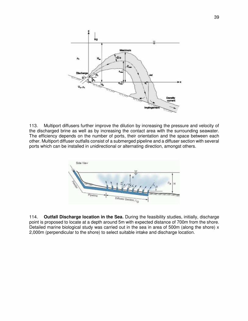
39
113. Multiport diffusers further improve the dilution by increasing the pressure and velocity of the discharged brine as well as by increasing the contact area with the surrounding seawater. The efficiency depends on the number of ports, their orientation and the space between each other. Multiport diffuser outfalls consist of a submerged pipeline and a diffuser section with several ports which can be installed in unidirectional or alternating direction, amongst others.
114. Outfall Discharge location in the Sea. During the feasibility studies, initially, discharge point is proposed to locate at a depth around 5m with expected distance of 700m from the shore. Detailed marine biological study was carried out in the sea in area of 500m (along the shore) x 2,000m (perpendicular to the shore) to select suitable intake and discharge location.
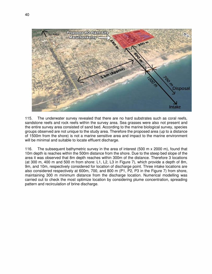
40
115. The underwater survey revealed that there are no hard substrates such as coral reefs, sandstone reefs and rock reefs within the survey area. Sea grasses were also not present and the entire survey area consisted of sand bed. According to the marine biological survey, species groups observed are not unique to the study area. Therefore the proposed area (up to a distance of 1500m from the shore) is not a marine sensitive area and impact to the marine environment will be minimal and suitable to locate effluent discharge. 116. The subsequent bathymetric survey in the area of interest (500 m x 2000 m), found that 10m depth is reaches within the 500m distance from the shore. Due to the steep bed slope of the area it was observed that 8m depth reaches within 300m of the distance. Therefore 3 locations (at 300 m, 400 m and 500 m from shore: L1, L2, L3 in Figure 7), which provide a depth of 8m, 9m, and 10m, respectively considered for location of discharge point. Three intake locations are also considered respectively at 600m, 700, and 800 m (P1, P2, P3 in the Figure 7) from shore, maintaining 300 m minimum distance from the discharge location. Numerical modelling was carried out to check the most optimize location by considering plume concentration, spreading pattern and recirculation of brine discharge.

41
Figure 7: Proposed Alternative Locations of Intake and outfall 117. Numerical modelling. Numerical modelling was conducted to finalize the location of the discharge point and configuration of the diffuser system to allow for maximum concentration in minimum area. The behaviour of this effluent after discharge was predicted by numerical modelling, using the CORMIX MIKE 21 Hydrodynamic and Advection-Dispersion Modelling System. This was configured using site specific data obtained from secondary sources and some of the field studies described in Section V (topography, bathymetry, tidal elevations and currents), and offshore wave data from the 2D Global Spectral Wind and Wave Models of the UK Meteorological Office. A representative wave climate (near-shore) fronting the interest area was obtained through wave transformation model (MIKE 21 Spectral Wave Model).. Input data on the characteristics of the plant, brine discharge and ambient seawater that are used in the numerical modelling are shown in Table 8. 118. Wave climate and effluent dispersion were simulated for the four main seasons that prevail in Sri Lanka (north-east and south-west monsoons and two inter-monsoon periods) under average and peak wind and wave conditions. A total of 32 cases, using two different recovery rates (45 and 50%) were simulated for all four seasonal periods, considering average (50% occurrence level of wind and wave) and peak (98% occurrence) environmental conditions.

42
Different potential discharge designs were also investigated via simulations incorporating local coastal data to determine the design with the most effective near-field dilution performance.
Table 8: Basic input data used in the dispersion modeling35 Parameter Average Value
1. Key plant design criteria
Water demand 0.33 m3/s
Recovery rate 45-50%
Intake flow rate 0.66 - 0.73 m3/s
Effluent flow rate 0.33 - 0.4 m3/s
2. Ambient sea water
Salinity 32 ppt
Temperature 25 °C
Density 1021.08 kg/m3
Total dissolved solids 35,000 mg/l
3. Brine effluent
Salinity 58 - 64 ppt
Temperature 25 °C
Density 1040.54 - 1045 kg/m3
Substance concentration/ residual chlorine 0.1 ppm
External blended effluents None
4. Discharge zone
Offshore slope 1 - 2 degrees
Diffuser velocity 3.5 - 4.5 m/s
119. The behaviour of discharge jet and mixing process in the receiving water body is predicted in separate mixing regions: In the first region (near-field region), the initial jet characteristics of momentum flux, buoyancy flux, and outfall geometry influence the jet trajectory and mixing. In this near-field region, outfall design usually affects the initial mixing characteristics As the turbulent plume travels further away from the source, the source characteristics become less important. Conditions existing in the ambient environment will control trajectory and dilution of the turbulent plume through buoyant spreading motions and passive diffusion due to ambient turbulence. A comprehensive advection dispersion study was carried out to estimate the spread of the high dense saline plume and recirculation, and optimize the location of the intake and outfall systems. The CORMIX model is employed for near-field process while MIKE 21 HD with MIKE 21 AD model is used to assess the movement of the concentrated brine and re-circulation in far-field. 120. Near-Field Behaviour. With the given discharge velocities in the range of 3.5 to 4.5m/s, the discharge will move as jet plume. Since the density of the brine discharge is high it will act as a negatively buoyant salinity discharge. The initial momentum of the discharge will lead to a very turbulent flow that will attempt to mix the fluid over the full depth available. This mixing will be resisted by the fact that the discharge is buoyant. The mixing will also cause ambient fluid to be entrained into the jet, reducing its momentum. This initial process is very important and reduces the excess salinity and temperature significantly. Once the discharge momentum has been reduced below a certain limit due to the dilution, the mixing will cease to be the dominant factor 35 NWSDB (2016): JKWSSP: Installation of Seawater Desalination Plant at Thalaiyadi. Interim Report 2_Numerical
Modelling (Revised). April 2017. Lanka Hydraulic Institute Ltd

43
and the discharge will transform into what is generally known as a plume. If the jet had mixed down to the bottom, it will generally detach from the mixing effect. After this the discharge enters the far- field. 121. Base quality parameters of receiving sea water & brine excess concentration. Based on the measurements ambient salinity level variation is observed as 28 ppt - 31ppt whereas TDS level was recorded in the range of 27,000 - 36,000mg/l. However 32 ppt of salinity and 35000 mg/l of TDS level is considered as a maximum value in order to provide assurance that plant can run reliably for the full range salinity and TDS variations. For the recovery rates of 45% and 50%, salinity levels of the brine will be 58.18 ppt and 64 ppt, and TDS will be 63,650 mg/l and 70,000 mg/l, respectively. Therefore an excess of 26.18 ppt (i.e. excess of ambient 32 ppt) of salinity level and 28,650mg/l of TDS level is used for the near field modelling of 45% recovery condition while the 32ppt of salinity and 35,000mg/l of TDS is used for the 50% recovery condition. Both the current potable water design demand (24,000 m3/day) and ultimate demand (48,000 m3/day) are considered for simulation to allow for future expansion as intended.. 122. Initial modelling was carried out considering 6.5m, 7m & 8m depth and later it was decided to move the discharge location further away to depth 8m to 10m in order to maintain certain distance from the shore. While selecting a location for an outfall it is important to place the discharge in sloping bed and hence the selected depth around 8-10m is acceptable. Multiport diffuser system is considered and sensitivity analysis was done by incorporating 2, 3, 5 & 10 number of ports, and found that 3 number of ports is more efficient which provides the appropriate discharge velocity to facilitate proper mixing within a short distance. Diffuser angles of 45o, 50 o and 60 o were considered, and 60 o gave the most elevated jet discharge, and will provide higher dilution rate while it reaches to the bed level. 123. Detailed modelling. To finalize the optimum location for an outfall three different water depths were considered as 8m, 9m and 10m. Simulations were selected to represent calm environmental conditions since the near field mixing is governed by jet characteristics only. Influence of environmental conditions like wave & current is not critical in near field region and hence wind speed & current speed were kept minimal. Further two diffuser alignments were considered: discharge parallel to current direction & discharge perpendicular to current direction. Both 45% recovery and 50% recovery levels were taken into consideration. 3 number of ports were selected for the present demand scenarios while 5 number of ports used for the future demand scenarios. 124. Present Demand (24,000 m3/day). Three number of diffuser ports were considered in this scenario. As per the modelling, the plume will reach up to a high of 4.65 m from the discharge point (which is 0.5 m above the seabed) and then flow down to the sea bed gradually. The highest plume point will be at a depth of 4.85m below the sea surface. Impingement location is 15.73 m away from the point of discharge and distance to the end of near field region is 21.9 m away from the discharge. Excess concentration is reduced to 5% of the discharge level at a distance of 12 m from the discharge point. Concentration (excess of ambient) at the end of near field is projected as 0.48 ppt (salinity) and 522 mg/l (TDS), which is about 1.5% of excess concentration At 50% recovery level, these values are projected at 0.81ppt and 888 mg/l respectively. 125. Future Demand (48,000 m3/day). It is proposed to use same configuration of discharge pipeline with additional diffusers(from 3 to 5 or 6). Higher dilution is obtained with 5 number of ports. For 45% recovery level, excess brine concentration & TDS levels at the end of near field are found as 0.47 ppt & 512 mg/l respectively. For 50% recovery level, excess brine concentration & TDS levels at the end of near field are found as 0.65 ppt & 714 mg/l respectively.

44
Figure 8: Near field plume model, and excess salinity
126. Far field modelling. As the turbulent plume travels further away from the discharge location, the jet characteristics become less important and three dimensional treatment of salinity dispersion is nearly changed to two dimensional treatments. Conditions existing in the ambient environment will control trajectory and dilution of the turbulent plume. Hydrodynamic nature of the proposed area and the dispersion characteristics were assessed during the study through numerical modelling. Established wave climate near the project site was used in this process. The objectives of those modelling are to assess the flow conditions, optimize the intake and outfall location, outfall configuration etc. Data relevant to bathymetry, topography, wind & waves, tide & currents, etc. were collected from various sources (secondary data from different agencies and primary data from the field studies). 127. Modelling was done considering all four climatic seasons, water level variation due to spring & neap tidal variations, different sea conditions (average & peak conditions), which covers all possible variations in the coastal environment. After the near field mixing the plume will

45
experience the far field mixing with the influence of the environmental factors. Parameters obtained at the end of near field were used as boundary conditions for the far field modelling. From the far field analysis it was found that the maximum increase of salinity level is 0.015ppt which represents the 0.05% of increase within the radius of 60-70m. Therefore, it can be concluding that at about 75m radius from the discharge location, salinity of the plume almost equals to the ambient condition and near 100% dilution can be expected. High impact zone is limited to a radius of 20-22m from the point of discharge where the initial dilution occurs. No recirculation of brine plume or TDS plume is observed during the studies and hence the proposed locations for intake & outfall can be considered during detail design stage. Following are the results of modelling:
(i) For 45% recovery: Brine exits the diffuser ports at a velocity of 4.28 m/s and at a salinity of 58.2 ppt (26.2 ppt excess). Within a mixing zone of 22m (near field), salinity will decreased to 0.48ppt (excess). In the far field (~60m), it will further reduces to 0.015 ppt. Similar dilution predicted in the case of TDS: it reaches to a value of 522mg/l at the end of near field and to 17.5mg/l in far field at a distance of 60m.
(ii) For 50% recovery: Brine exits the diffuser ports at a velocity of 3.5 m/s and at a salinity of 64 ppt (32 ppt excess). Salinity will decreased to 0.81ppt excess in the near field, and 0.016ppt excess in the far field (~60—70m). Similarly, the TDS of is deceased to 888mg/l and 17.5 mg/l respectively.
128. Therefore, it can be concluding that at about 75m radius from the discharge location, salinity of the plume almost equals the ambient condition and nearly 100% dilution can be expected. Highly impact zone is limited to a radius of 20-22m from the point of discharge where the initial dilution occurs. Further it should be noted that model scenarios were done by aligning the diffusers towards the current direction to represent the worst case scenario.
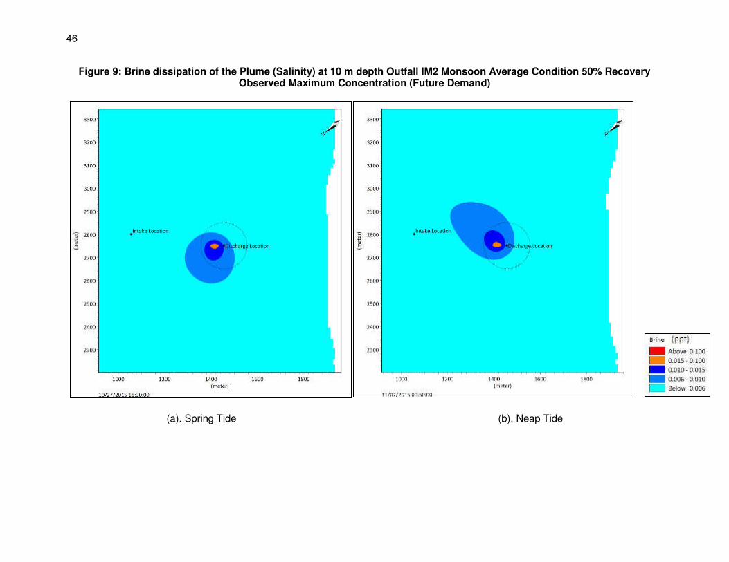
46
Figure 9: Brine dissipation of the Plume (Salinity) at 10 m depth Outfall IM2 Monsoon Average Condition 50% Recovery Observed Maximum Concentration (Future Demand)
(a). Spring Tide (b). Neap Tide

47
Figure 10: Brine dissipation of the Plume (Salinity) at 10 m depth Outfall IM2 Monsoon Average Condition 50% Recovery Observed Maximum Spreading (Future Demand)
(a). Spring Tide (b). Neap Tide
48
129. Brine Characteristics. Desalination process principally generates permeate (product) and a concentrated effluent (waste stream) called brine, which is nearly twice as saline as raw sea water intake of the plant. In addition to concentrate, desalination plant discharges may also include other treatment process side-streams, such as spent pre-treatment filter backwash water, SWRO membrane rinsing water, and treated membrane cleaning water. Besides the desalination concentrate also consists of dissolved solids, if present in the feed water, which are rejected by the RO membranes. Concentrate from seawater desalination plants using open ocean intakes typically has the same colour, door, oxygen content and transparency as the source seawater from which the concentrate was produced. Therefore, concentrate discharged to ocean does not typically change its physical characteristics or aesthetic impact on the aquatic environment, except for its density. E. Alternative Analysis for Transmission Main
130. A new transmission main pipeline of 800 mm diameter will be laid from RODP to the existing water main on Jaffna-Kandy road that conveys treated water to Jaffna for supply to consumers. Pipeline alignment is chosen in such a way that it avoids any environmentally sensitive areas, and also avoids the need to acquire land from private owners to lay the pipeline. The pipeline is aligned along the existing road connecting Thalaiyadi to Jaffna – Kandy Road. It will be buried in the road earthen shoulder beside the tarmac within the road right of way. There are no trees, except bushes and shrubs at some places. The road crosses Vadamarachchi lagoon – at this section road is built on a bund, and at centre a culvert/bridge constructed to ensure continuity of lagoon. There are mangroves in the lagoon along the road as well. Pipeline in the lagoon will aligned away from the road avoiding the need to cut mangroves. 131. Also, to minimize disturbance to water body, pipeline at this lagoon portion will be laid on concrete supports at a distance of 20-25 m, over which the pipe will be placed. Supports will be constructed using less invasive techniques, either using precast blocks or cast in situ using simple processes. Precast pipes of diameter 1 m will be placed in the lagoon vertically by a crane placed on the road, and driven to a certain depth. Subsequently this will be filled with concrete to create a column. This process will be repeated till it reaches the required height. This method will be less intrusive and there will be any notable degradation of water quality.
IV. DESCRIPTION OF THE PROJECT
A. Project Overview
132. As noted in Chapter 1, the project will involve construction and operation of a reverse osmosis desalination plant (RODP) on the northern coast of the Jaffna Peninsula at Thalaiyadi, near Pallai (Figure 1) to extract drinking water from seawater at a volume of 24,000 m3/day. The plant will occupy an area of around 4 ha (200 x 200 m) and seawater will be sourced from the adjacent coastal zone at a depth of around 12 m, with the brine effluent being returned to the sea through diffusers to ensure rapid mixing and dispersal. The pipelines will extend approximately 500 m (outfall) and 800 m (intake) from the beach and will be located at least 300 m apart (Figure 1). Project also includes construction of potable water storage and pumping infrastructure within RODP compound, and a potable water conveyance pipeline from RODP to water delivery point at junction Jaffa-Kandy Road (Figure 2). 133. As the project will be implemented via a Design-Build-Operate (DBO) contract, detailed design of project will be carried out by the selected DBO Contractor. Project description provided here is as per the feasibility study report (Appendix E) and the Design, Build & Operate (DBO) bid
49
document for selecting a contractor to design, and built and operate the seawater desalination plant (specifically Section 6, which deals with Employers requirements of DBO contract), which details out the project requirements, key systems and facilities, general engineering and construction approach, design and operation specifications, under which the plant is to be designed, constructed and operated. During the detailed design stage, the DBO contractor will use these requirement as base and further develop and fine-tune as required, and therefore the description provided here will remain same, although some details may change as the project develops in the design stage. 134. In some cases, the tender documents encourage flexibility and innovation by the contractor by specifying what must be achieved rather than the method of achieving it, so these elements may change. An example is the pre-treatment facility, where the bid document defines pre-treatment only in outline, giving flexibility to contractor to propose a suitable pre-treatment method. The bid document specify the minimum water quality that must be achieved in the pre-treatment filtrate to protect the RO membranes (see Table 10) and provide examples of pre-treatment methods that may be considered, along with others that may be proposed by the Contractor (filtration - “pressured” or “submerged” membrane filtration and “gravity” or “pressurised” granular media filtration). Contractor may propose alternative approaches with Client approval, but within the parameters defined in bid document. The tender document thus mention the base case, and this do not allow contractor to propose any inferior facilities (from technical-economic and as well as environmental considerations), but to improve make them superior or comply at least with the base case provided in the tender documents. 135. It is however unlikely that there will be changes in the location of project components, which are finalized at this stage based on environment and techno-economic considerations. The bid document also require the contractor to review the EIA and EMP during the detailed design phase and subsequently every six months throughout construction and operational phases, and to update both documents if there have been significant changes in the project or if unanticipated impacts have occurred. In this way, any changes in design or operation will be incorporated into a revised impact assessment as necessary, and this will be regularly re-evaluated and mitigation will be revised where needed, to ensure continuing and robust environmental protection throughout the life of the project. B. Plant Production Capacity
136. Proposed plant capacity is 24 MLD (24,000 m3/day) of potable water from seawater. To provide a flexible water supply, the plant will be designed to operate reliably and cost effectively at turn-down capacity of 6 MLD which is nominally 25 % of its design potable water production flow of 24 MLD. Under such minimum production capacity only one of four (4) seawater reverse osmosis (SWRO) desalination trains (racks) will be in operation. Each of the RO trains will be capable of operating efficiently at nominally 6 MLD of potable water production capacity and achieve highest efficiency and flexibility of operation at other capacities of 12 MLD, 18 MLD and 24 MLD of Potable Water. The proposed potable water requirement for first three years of Operation Service Period would be 6 MLD, 12 MLD and 18 MLD respectively and from the fourth year onwards 24 MLD. A potable water storage tank working capacity of 10 ML (10,000 m³) is considered in the sizing and design of the RO training cleaning system so that there is no net reduction in the SWRO Desalination Plant’s capability to export a net 24 MLD capacity, even when one RO train is being cleaned. 137. The plant production capacity availability factor will be no less than 96 % - i.e. the plant will produce potable water of at least 24 MLD for at least 350 days per year on a running annual

50
average basis. The plant will be designed and operated such that the scheduled plant shutdown for the complete plant is minimized and all shutdown activities for individual (or groups of 6MLD trains) is completed within a maximum of 15 non-sequential days per year (up to 1.25 days per month of plant down time to accommodate planned maintenance activities. According to bid document, sodium hypochlorite will be used for disinfection and the control of biological growth throughout the plant. Chlorine gas is to be used for disinfecting the potable water. C. Project Components
138. The RODP will include the following components, shown schematically in Figure 11: (i) Offshore seawater intake; (ii) Offshore concentrate (brine) outfall equipped with diffusers; (iii) Pumping equipment and pipes to connect the intake and outfall to on-land
treatment facilities; (iv) Facilities and equipment for two-stage pre-treatment of the source seawater to
provide a suitable quality for membrane desalination; (v) Single-pass state-of-the-art seawater reverse osmosis membrane system,
equipped with energy-recovery devices; (vi) Post-treatment system for re-mineralisation and disinfection of brine effluent prior
to discharge; (vii) Separate buildings housing the RO system, pre- and post-treatment facilities,
intake pumps and plant operations staff; (viii) On-site product water storage tanks and pump station; (ix) Electrical substation with separate connection to the power grid; (x) Emergency power supply from an independent power circuit.
139. The Potable Water Conveyance System shall comprise:
(i) 1 above-ground reinforced concrete potable water storage tank (10,000 m3); (ii) On-site Pump station building with all required facilities (pumps of 2 X 6 MLD and
3 x 12 MLD Pumps); suction and delivery pipework (iii) Potable water transmission line (8 kilometres long) (iv) All required pipework connections, valves, valves, pipe supports, bridge crossings,
etc., instrumentation, electrical and necessary works (v) Potable Water Quality monitoring system; (vi) Floor space for installation of additional equipment to reach 48 MLD capacity; (vii) SCADA
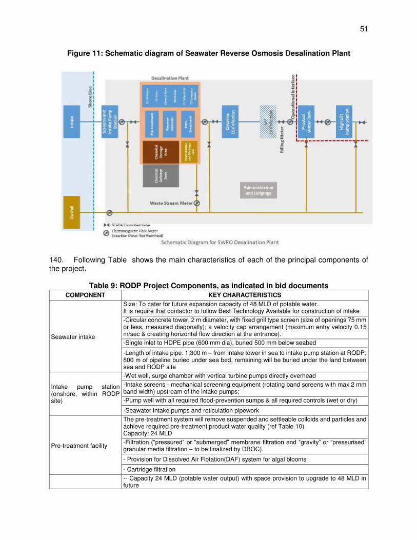
51
Figure 11: Schematic diagram of Seawater Reverse Osmosis Desalination Plant
140. Following Table shows the main characteristics of each of the principal components of the project.
Table 9: RODP Project Components, as indicated in bid documents
COMPONENT KEY CHARACTERISTICS
Seawater intake
Size: To cater for future expansion capacity of 48 MLD of potable water. It is require that contactor to follow Best Technology Available for construction of intake
-Circular concrete tower, 2 m diameter, with fixed grill type screen (size of openings 75 mm or less, measured diagonally); a velocity cap arrangement (maximum entry velocity 0.15 m/sec & creating horizontal flow direction at the entrance).
-Single inlet to HDPE pipe (600 mm dia), buried 500 mm below seabed
-Length of intake pipe: 1,300 m – from Intake tower in sea to intake pump station at RODP; 800 m of pipeline buried under sea bed, remaining will be buried under the land between sea and RODP site
Intake pump station (onshore, within RODP site)
-Wet well, surge chamber with vertical turbine pumps directly overhead
-Intake screens - mechanical screening equipment (rotating band screens with max 2 mm band width) upstream of the intake pumps;
-Pump well with all required flood-prevention sumps & all required controls (wet or dry)
-Seawater intake pumps and reticulation pipework
Pre-treatment facility
The pre-treatment system will remove suspended and settleable colloids and particles and achieve required pre-treatment product water quality (ref Table 10) Capacity: 24 MLD
-Filtration (“pressured” or “submerged” membrane filtration and “gravity” or “pressurised” granular media filtration – to be finalized by DBOC).
- Provision for Dissolved Air Flotation(DAF) system for algal blooms
- Cartridge filtration
-- Capacity 24 MLD (potable water output) with space provision to upgrade to 48 MLD in future
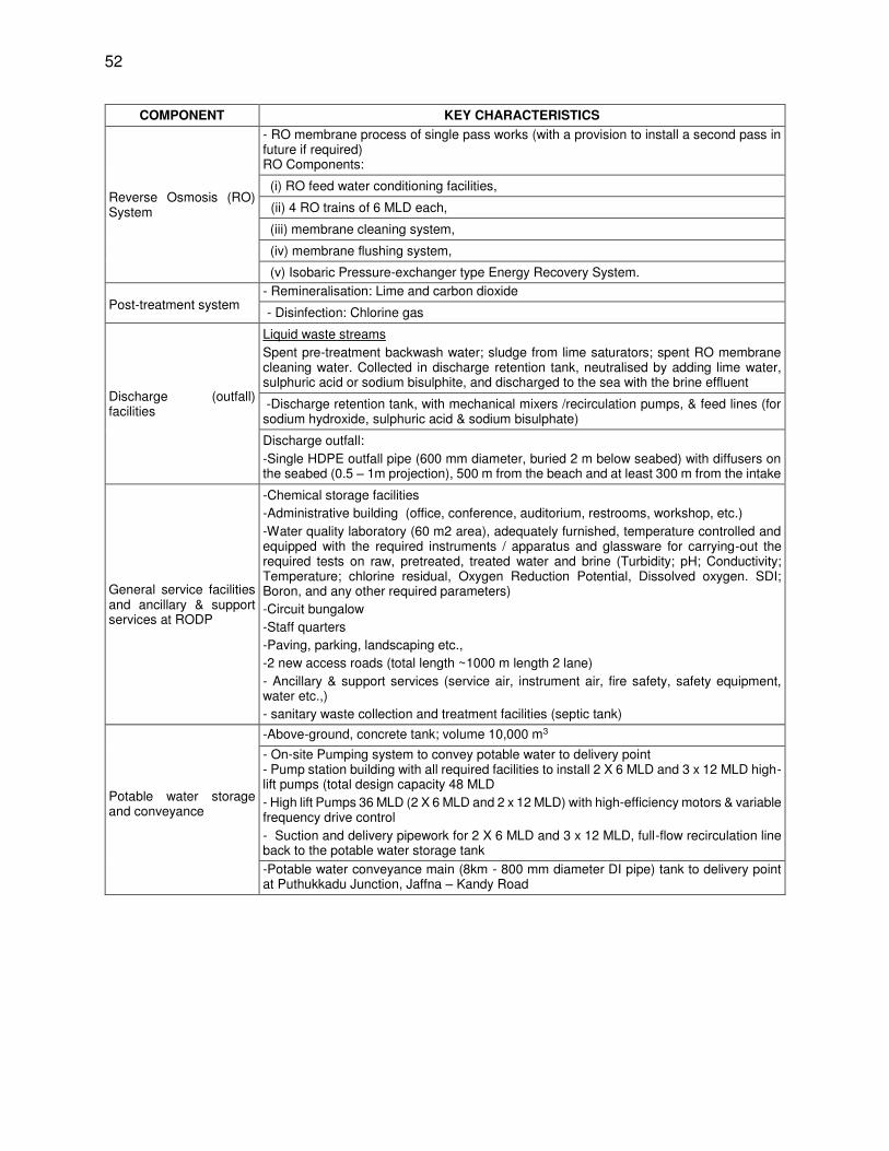
52
COMPONENT KEY CHARACTERISTICS
Reverse Osmosis (RO) System
- RO membrane process of single pass works (with a provision to install a second pass in future if required) RO Components:
(i) RO feed water conditioning facilities,
(ii) 4 RO trains of 6 MLD each,
(iii) membrane cleaning system,
(iv) membrane flushing system,
(v) Isobaric Pressure-exchanger type Energy Recovery System.
Post-treatment system - Remineralisation: Lime and carbon dioxide
- Disinfection: Chlorine gas
Discharge (outfall) facilities
Liquid waste streams Spent pre-treatment backwash water; sludge from lime saturators; spent RO membrane cleaning water. Collected in discharge retention tank, neutralised by adding lime water, sulphuric acid or sodium bisulphite, and discharged to the sea with the brine effluent
-Discharge retention tank, with mechanical mixers /recirculation pumps, & feed lines (for sodium hydroxide, sulphuric acid & sodium bisulphate)
Discharge outfall: -Single HDPE outfall pipe (600 mm diameter, buried 2 m below seabed) with diffusers on the seabed (0.5 – 1m projection), 500 m from the beach and at least 300 m from the intake
General service facilities and ancillary & support services at RODP
-Chemical storage facilities -Administrative building (office, conference, auditorium, restrooms, workshop, etc.) -Water quality laboratory (60 m2 area), adequately furnished, temperature controlled and equipped with the required instruments / apparatus and glassware for carrying-out the required tests on raw, pretreated, treated water and brine (Turbidity; pH; Conductivity; Temperature; chlorine residual, Oxygen Reduction Potential, Dissolved oxygen. SDI; Boron, and any other required parameters) -Circuit bungalow -Staff quarters -Paving, parking, landscaping etc., -2 new access roads (total length ~1000 m length 2 lane) - Ancillary & support services (service air, instrument air, fire safety, safety equipment, water etc.,) - sanitary waste collection and treatment facilities (septic tank)
-Above-ground, concrete tank; volume 10,000 m3
Potable water storage and conveyance
- On-site Pumping system to convey potable water to delivery point - Pump station building with all required facilities to install 2 X 6 MLD and 3 x 12 MLD high-lift pumps (total design capacity 48 MLD - High lift Pumps 36 MLD (2 X 6 MLD and 2 x 12 MLD) with high-efficiency motors & variable frequency drive control - Suction and delivery pipework for 2 X 6 MLD and 3 x 12 MLD, full-flow recirculation line back to the potable water storage tank
-Potable water conveyance main (8km - 800 mm diameter DI pipe) tank to delivery point at Puthukkadu Junction, Jaffna – Kandy Road
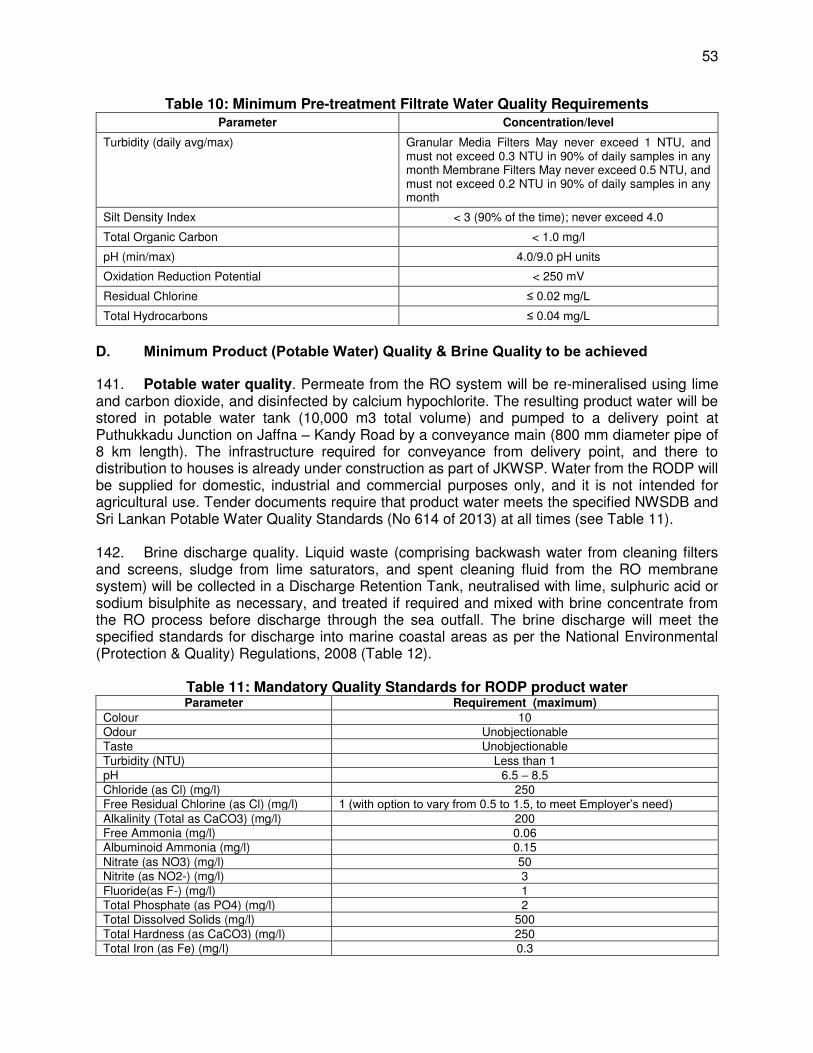
53
Table 10: Minimum Pre-treatment Filtrate Water Quality Requirements Parameter Concentration/level
Turbidity (daily avg/max) Granular Media Filters May never exceed 1 NTU, and must not exceed 0.3 NTU in 90% of daily samples in any month Membrane Filters May never exceed 0.5 NTU, and must not exceed 0.2 NTU in 90% of daily samples in any month
Silt Density Index < 3 (90% of the time); never exceed 4.0
Total Organic Carbon < 1.0 mg/l
pH (min/max) 4.0/9.0 pH units
Oxidation Reduction Potential < 250 mV
Residual Chlorine ≤ 0.02 mg/L
Total Hydrocarbons ≤ 0.04 mg/L
D. Minimum Product (Potable Water) Quality & Brine Quality to be achieved
141. Potable water quality. Permeate from the RO system will be re-mineralised using lime and carbon dioxide, and disinfected by calcium hypochlorite. The resulting product water will be stored in potable water tank (10,000 m3 total volume) and pumped to a delivery point at Puthukkadu Junction on Jaffna – Kandy Road by a conveyance main (800 mm diameter pipe of 8 km length). The infrastructure required for conveyance from delivery point, and there to distribution to houses is already under construction as part of JKWSP. Water from the RODP will be supplied for domestic, industrial and commercial purposes only, and it is not intended for agricultural use. Tender documents require that product water meets the specified NWSDB and Sri Lankan Potable Water Quality Standards (No 614 of 2013) at all times (see Table 11). 142. Brine discharge quality. Liquid waste (comprising backwash water from cleaning filters and screens, sludge from lime saturators, and spent cleaning fluid from the RO membrane system) will be collected in a Discharge Retention Tank, neutralised with lime, sulphuric acid or sodium bisulphite as necessary, and treated if required and mixed with brine concentrate from the RO process before discharge through the sea outfall. The brine discharge will meet the specified standards for discharge into marine coastal areas as per the National Environmental (Protection & Quality) Regulations, 2008 (Table 12).
Table 11: Mandatory Quality Standards for RODP product water Parameter Requirement (maximum)
Colour 10 Odour Unobjectionable Taste Unobjectionable Turbidity (NTU) Less than 1 pH 6.5 – 8.5 Chloride (as Cl) (mg/l) 250 Free Residual Chlorine (as Cl) (mg/l) 1 (with option to vary from 0.5 to 1.5, to meet Employer’s need) Alkalinity (Total as CaCO3) (mg/l) 200 Free Ammonia (mg/l) 0.06 Albuminoid Ammonia (mg/l) 0.15 Nitrate (as NO3) (mg/l) 50 Nitrite (as NO2-) (mg/l) 3 Fluoride(as F-) (mg/l) 1 Total Phosphate (as PO4) (mg/l) 2 Total Dissolved Solids (mg/l) 500 Total Hardness (as CaCO3) (mg/l) 250 Total Iron (as Fe) (mg/l) 0.3
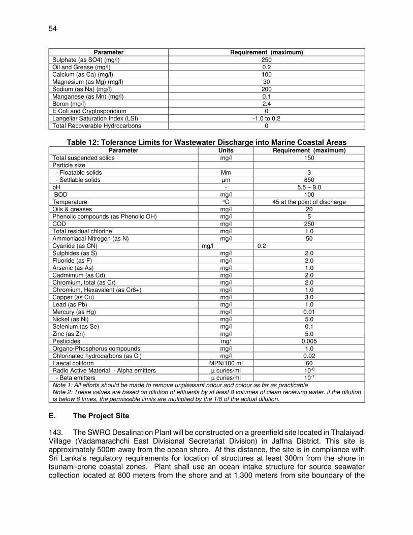
54
Parameter Requirement (maximum)
Sulphate (as SO4) (mg/l) 250 Oil and Grease (mg/l) 0.2 Calcium (as Ca) (mg/l) 100 Magnesium (as Mg) (mg/l) 30 Sodium (as Na) (mg/l) 200 Manganese (as Mn) (mg/l) 0.1 Boron (mg/l) 2.4 E Coli and Cryptosporidium 0 Langeliar Saturation Index (LSI) -1.0 to 0.2 Total Recoverable Hydrocarbons 0
Table 12: Tolerance Limits for Wastewater Discharge into Marine Coastal Areas
Parameter Units Requirement (maximum)
Total suspended solids mg/l 150 Particle size - Floatable solids Mm 3 - Settlable solids µm 850 pH - 5.5 – 9.0 BOD mg/l 100 Temperature oC 45 at the point of discharge Oils & greases mg/l 20 Phenolic compounds (as Phenolic OH) mg/l 5 COD mg/l 250 Total residual chlorine mg/l 1.0 Ammoniacal Nitrogen (as N) mg/l 50 Cyanide (as CN) mg/l 0.2 Sulphides (as S) mg/l 2.0 Fluoride (as F) mg/l 2.0 Arsenic (as As) mg/l 1.0 Cadmimum (as Cd) mg/l 2.0 Chromium, total (as Cr) mg/l 2.0 Chromium, Hexavalent (as Cr6+) mg/l 1.0 Copper (as Cu) mg/l 3.0 Lead (as Pb) mg/l 1.0 Mercury (as Hg) mg/l 0.01 Nickel (as Ni) mg/l 5.0 Selenium (as Se) mg/l 0,1 Zinc (as Zn) mg/l 5.0 Pesticides mg/ 0.005 Organo-Phosphorus compounds mg/l 1.0 Chlorinated hydrocarbons (as Cl) mg/l 0.02 Faecal coliform MPN/100 ml 60 Radio Active Material - Alpha emitters µ curies/ml 10-8 - Beta emitters µ curies/ml 10-7 Note 1: All efforts should be made to remove unpleasant odour and colour as far as practicable Note 2: These values are based on dilution of effluents by at least 8 volumes of clean receiving water. if the dilution is below 8 times, the permissible limits are multiplied by the 1/8 of the actual dilution.
E. The Project Site
143. The SWRO Desalination Plant will be constructed on a greenfield site located in Thalaiyadi Village (Vadamarachchi East Divisional Secretariat Division) in Jaffna District. This site is approximately 500m away from the ocean shore. At this distance, the site is in compliance with Sri Lanka’s regulatory requirements for location of structures at least 300m from the shore in tsunami-prone coastal zones. Plant shall use an ocean intake structure for source seawater collection located at 800 meters from the shore and at 1,300 meters from site boundary of the
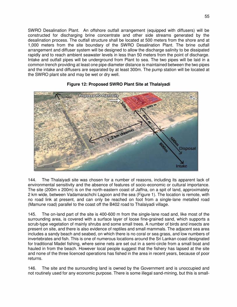
55
SWRO Desalination Plant. An offshore outfall arrangement (equipped with diffusers) will be constructed for discharging brine concentrate and other side streams generated by the desalination process. The outfall structure shall be located at 500 meters from the shore and at 1,000 meters from the site boundary of the SWRO Desalination Plant. The brine outfall arrangement and diffuser system will be designed to allow the discharge salinity to be dissipated rapidly and to reach ambient seawater levels in less than 50 meters from the point of discharge. Intake and outfall pipes will be underground from Plant to sea. The two pipes will be laid in a common trench providing at least one pipe diameter distance is maintained between the two pipes and the intake and diffusers are separated by at least 300m. The pump station will be located at the SWRO plant site and may be wet or dry well.
Figure 12: Proposed SWRO Plant Site at Thalaiyadi
144. The Thalaiyadi site was chosen for a number of reasons, including its apparent lack of environmental sensitivity and the absence of features of socio-economic or cultural importance. The site (200m x 200m) is on the north-eastern coast of Jaffna, on a spit of land, approximately 2 km wide, between Vadamarachchi Lagoon and the sea (Figure 1). The location is remote, with no road link at present, and can only be reached on foot from a single-lane metalled road (Mamune road) parallel to the coast off the B402 road to Thalaiyadi village. 145. The on-land part of the site is 400-600 m from the single-lane road and, like most of the surrounding area, is covered with a surface layer of loose fine-grained sand, which supports a scrub-type vegetation of mainly shrubs and some small trees. A number of birds and insects are present on site, and there is also evidence of reptiles and small mammals. The adjacent sea area includes a sandy beach and seabed, on which there is no coral or sea grass, and low numbers of invertebrates and fish. This is one of numerous locations around the Sri Lankan coast designated for traditional Madel fishing, where seine nets are set out in a semi-circle from a small boat and hauled in from the beach. However local people suggest that the fishery has lapsed at the site and none of the three licenced operations has fished in the area in recent years, because of poor returns. 146. The site and the surrounding land is owned by the Government and is unoccupied and not routinely used for any economic purpose. There is some illegal sand-mining, but this is small-

56
scale and infrequent, involving manual shovelling of sand into a dump truck. There are three temporary fishing huts north-west of the site, which are occupied occasionally by small numbers of fishermen. The nearest inhabitation is 750 m south-east, in the villages of Thalaiyadi, Maruthankerny North and Maruthankerny South, where there are 1,351 inhabitants. Artisanal fishing is the main occupation, and most households are poor. These villages suffered several deaths during the civil war and in the tsunami of 2004, when all of the houses in Thalaiyadi and Maruthankerny North were destroyed. Both villages were relocated 300 m inland from the coast, where each family was given a house and a plot of land. 147. Operational advantages of the site include a somewhat more steeply sloping seabed than other locations, providing deeper water closer to the beach, which will require shorter intake and outfall pipeline lengths. The site is also close to both a power supply and the new water distribution network, so costs for these aspects will be reduced. Local sea currents are also expected to promote mixing and dispersion of the effluent, thus reducing the area affected by the brine concentrate.
Photo 1: Single track Mamune Road near the project site (south-easterly view)

57
Photo 2: View of Project Site (Aug 2016)
Photo 3: Fishing huts north-west of the project site

58
148. As stated above, at present RODP plant site is approachable only on foot as there is no access road exists. Two new approach roads (one from east and the other from south) will be constructed to connect the site with the existing road network. On eastern site, approach road will be constructed along the intake & outfall pipeline route from site up to the existing Mamune road, that separates the beach on the north/northeast and scrub land on the west/southwest where RODP site is selected. Running northwest-southeast, Mamune road connects Soranpattu – Thalaiyadi Road on the southeast, and in northwest it connects to some villages. On the south western side of the site, the internal main road of Thalaiyadi village will be extended up to the site by laying a new road for about 500 m. This internal connects to Soranpattu – Thalaiyadi Road.
Figure 13: Proposed SWRO Plant Site & Access Roads
149. Sites for potable water storage & conveyance system. The potable water storage tank and pumping station will be developed within the RODP compound in Thalaiyadi, which is described above. The conveyance pipeline from storage tank to the water delivery point at Puthukkadu Junction on Jaffna – Kandy (A9) Highway will be laid along existing roads. The pipeline will be buried along the new approach road on southern side – Thalaiyadi internal road, and then along the Soranpattu – Thalaiyadi Road connecting to the existing pumping main on Jaffna – Kandy Road junction. Connection to the existing line, which will require crossing of A9 highway will be by trenchless method. 150. As the pipe is completely aligned along the road, and within the earthen shoulder of the road besides the tarmac, there are no sensitive environmental features or trees to be disturbed. There may be need to clear shrubs and bushes at one or two locations, but this is no significant.

59
151. For about 1.5 km, the road traverses Vadamarachchi lagoon. Road formed as a bund separating the lagoon area, except for a short length, where a bridge is provided which connects the lagoon that spread on both sides of the road. At lagoon section, for about 700 m there is adequate space along the tarmac and pipe will buried along the road without disturbing the lagoon area, and for the remaining 800 m, pipeline will be laid on concrete supports in the lagoon. At this portion, there are mangroves in the lagoon along the road, and therefore pipeline will be aligned sufficiently away from the road so that no mangroves are removed or damaged.
Figure 14: Potable Water Conveyance Pipeline Route
Pumping main alignment - Soranpattu – Thalaiyadi Road

60
Start of Vadamarachchi – pipe on bridge View of Vadamarachchi lagoon
Pipe bridge route avoiding mangroves along
the road in lagoon Road through village habitation
Internal village road for pipe alignment View of new approach road alignment
F. Indicative Project Implementation Schedule
152. An indicative timeframe for this project is given in Figure 15. Design Phase is 6 months, construction Phase is 2 years, and the Operation Phase is 7 years. Bid documents requires that bidders are to prepare their own schedules within the overall project period. The project is currently under bidding stage, contract is likely to be awarded by the end of 2017. Construction work will start in January 2018, and will take about 2 years to complete inn by the end of 2020.
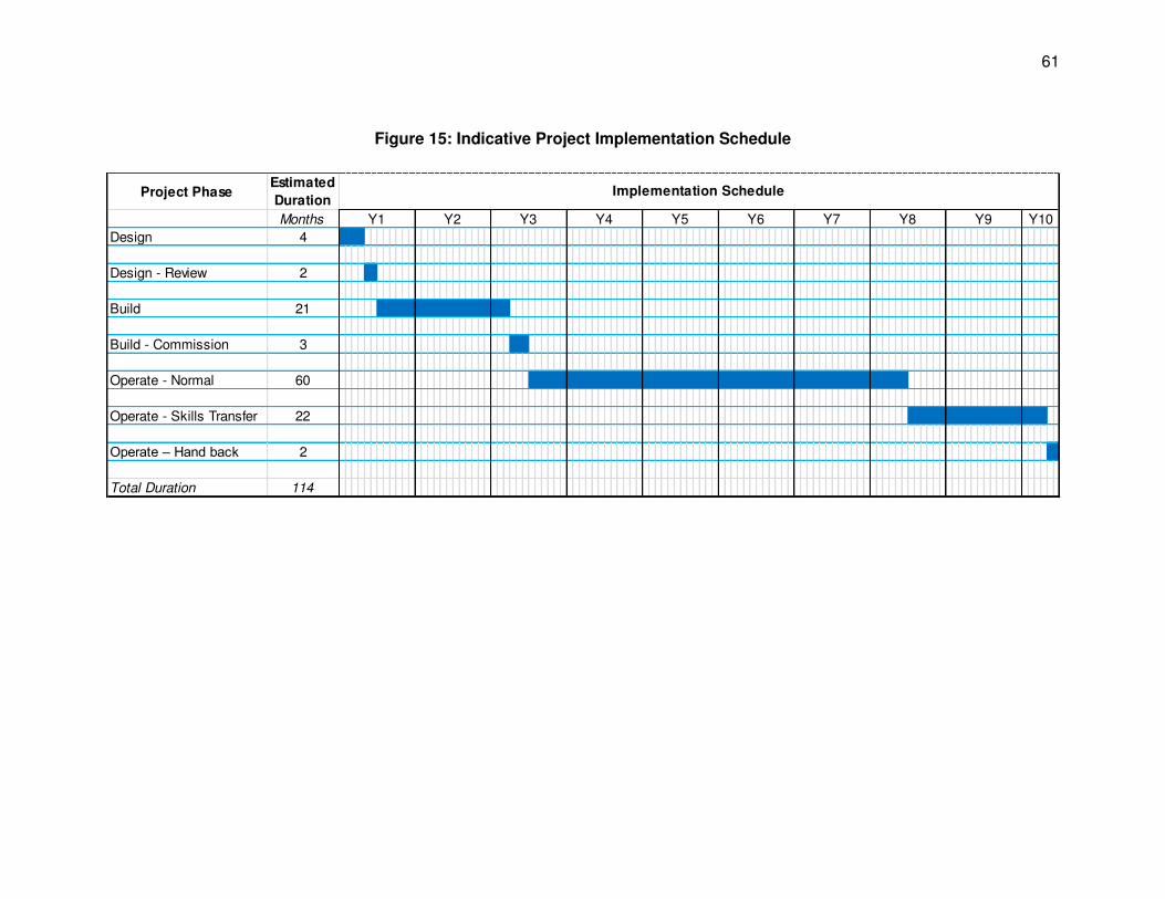
61
Figure 15: Indicative Project Implementation Schedule
Project PhaseEstimated
Duration
Months
Design 4
Design - Review 2
Build 21
Build - Commission 3
Operate - Normal 60
Operate - Skills Transfer 22
Operate – Hand back 2
Total Duration 114
Y7 Y8 Y9 Y10
Implementation Schedule
Y1 Y2 Y3 Y4 Y5 Y6
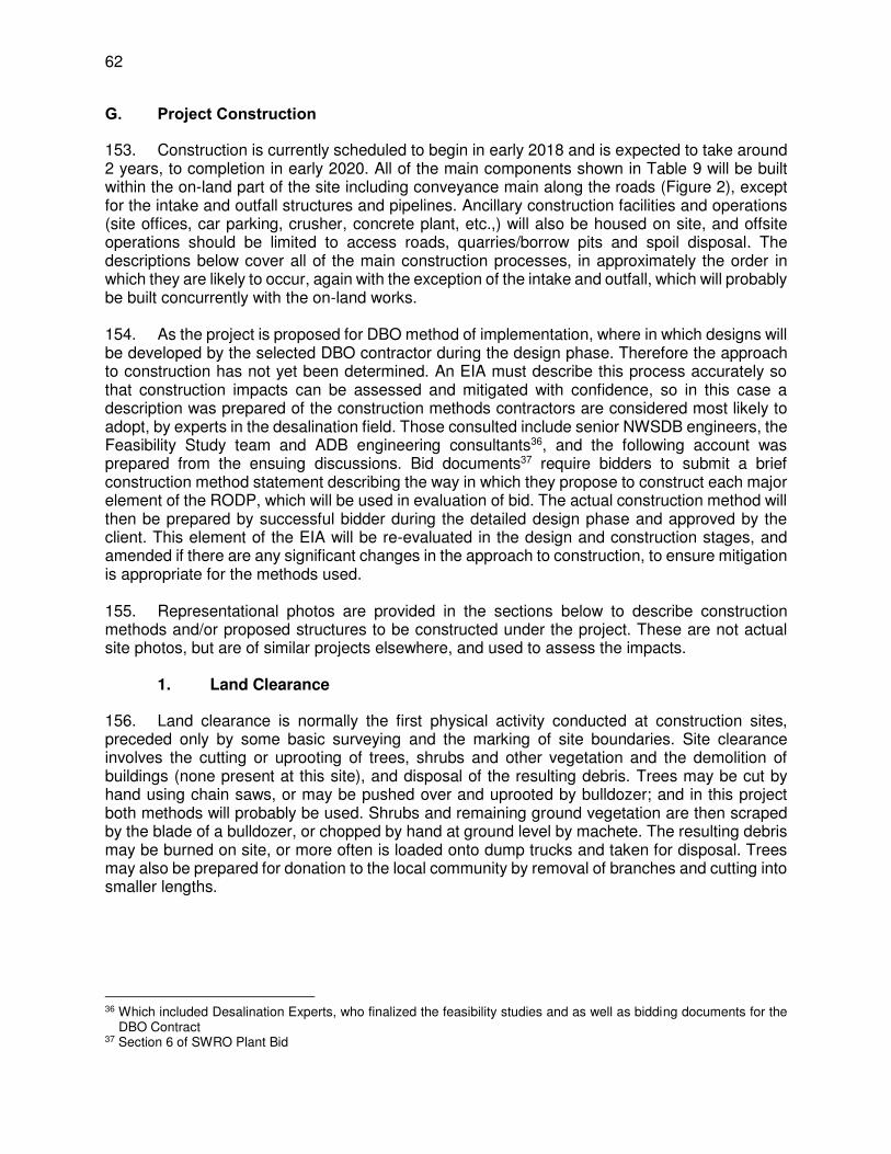
62
G. Project Construction
153. Construction is currently scheduled to begin in early 2018 and is expected to take around 2 years, to completion in early 2020. All of the main components shown in Table 9 will be built within the on-land part of the site including conveyance main along the roads (Figure 2), except for the intake and outfall structures and pipelines. Ancillary construction facilities and operations (site offices, car parking, crusher, concrete plant, etc.,) will also be housed on site, and offsite operations should be limited to access roads, quarries/borrow pits and spoil disposal. The descriptions below cover all of the main construction processes, in approximately the order in which they are likely to occur, again with the exception of the intake and outfall, which will probably be built concurrently with the on-land works. 154. As the project is proposed for DBO method of implementation, where in which designs will be developed by the selected DBO contractor during the design phase. Therefore the approach to construction has not yet been determined. An EIA must describe this process accurately so that construction impacts can be assessed and mitigated with confidence, so in this case a description was prepared of the construction methods contractors are considered most likely to adopt, by experts in the desalination field. Those consulted include senior NWSDB engineers, the Feasibility Study team and ADB engineering consultants36, and the following account was prepared from the ensuing discussions. Bid documents37 require bidders to submit a brief construction method statement describing the way in which they propose to construct each major element of the RODP, which will be used in evaluation of bid. The actual construction method will then be prepared by successful bidder during the detailed design phase and approved by the client. This element of the EIA will be re-evaluated in the design and construction stages, and amended if there are any significant changes in the approach to construction, to ensure mitigation is appropriate for the methods used. 155. Representational photos are provided in the sections below to describe construction methods and/or proposed structures to be constructed under the project. These are not actual site photos, but are of similar projects elsewhere, and used to assess the impacts.
1. Land Clearance
156. Land clearance is normally the first physical activity conducted at construction sites, preceded only by some basic surveying and the marking of site boundaries. Site clearance involves the cutting or uprooting of trees, shrubs and other vegetation and the demolition of buildings (none present at this site), and disposal of the resulting debris. Trees may be cut by hand using chain saws, or may be pushed over and uprooted by bulldozer; and in this project both methods will probably be used. Shrubs and remaining ground vegetation are then scraped by the blade of a bulldozer, or chopped by hand at ground level by machete. The resulting debris may be burned on site, or more often is loaded onto dump trucks and taken for disposal. Trees may also be prepared for donation to the local community by removal of branches and cutting into smaller lengths.
36 Which included Desalination Experts, who finalized the feasibility studies and as well as bidding documents for the
DBO Contract 37 Section 6 of SWRO Plant Bid

63
2. New Approach / Access Roads
157. As there is currently no road link to the project site, creation of access roads will be one of the earliest construction activities, to enable vehicles carrying materials, equipment and workers to reach the site. Two new approach roads will be constructed to provide motarable access to the site, and connect it with the existing road network in the area. Besides new roads, this will also involve improving and widening the existing single-track road that runs parallel to the beach (Mamune Road), and also an internal road in Thalaiyadi, up their connection with Soranpattu – Thalaiyadi Road. Running northwest-southeast, separating the beach on the north/northeast and scrub land on the west/southwest (where RODP site is located), it connects Soranpattu – Thalaiyadi Road on the southeast, and some villages in northwest. 158. On north-eastern side of the site, a new road (470 m length, 2 lane) will be constructed along the intake & outfall pipeline route from RODP site, and up to the Mamune road to provide seamless connectivity with Jaffna-Kandy (A9) highway via Soranpattu – Thalaiyadi Road. As the roads will be used for transport of construction materials and prefabricated components from distant sources, Mamune road and Soranpattu – Thalaiyadi Road may need to be strengthened to become suitable for heavy traffic, especially at locations like cross drainage works (culverts, bridges etc.,). 159. It is also proposed to construct another access road (545 m length, 2-lane) from the south western side of the RODP site, which will connect it to an internal main road of Thalaiyadi village, that in turn connects Soranpattu – Thalaiyadi Road. This access road is proposed at the request of local villagers, which will provide easy connectivity to Mamune road. This road however will not be used for heavy construction vehicles as it passes through the village habitation. Along with the new approach road, the internal main road of Thalaiyadi village will also be strengthened and resurfaced.
View of Northeast Approach Road Alignment Internal access road in Thalaiyadi
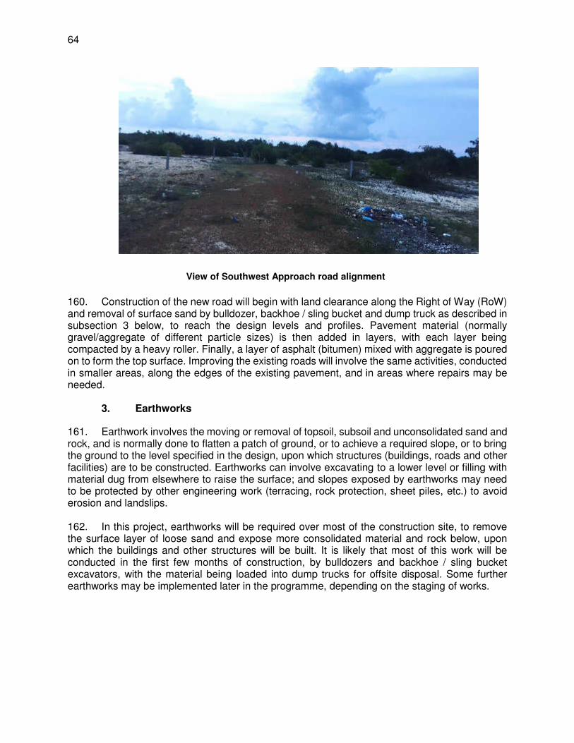
64
View of Southwest Approach road alignment
160. Construction of the new road will begin with land clearance along the Right of Way (RoW) and removal of surface sand by bulldozer, backhoe / sling bucket and dump truck as described in subsection 3 below, to reach the design levels and profiles. Pavement material (normally gravel/aggregate of different particle sizes) is then added in layers, with each layer being compacted by a heavy roller. Finally, a layer of asphalt (bitumen) mixed with aggregate is poured on to form the top surface. Improving the existing roads will involve the same activities, conducted in smaller areas, along the edges of the existing pavement, and in areas where repairs may be needed.
3. Earthworks
161. Earthwork involves the moving or removal of topsoil, subsoil and unconsolidated sand and rock, and is normally done to flatten a patch of ground, or to achieve a required slope, or to bring the ground to the level specified in the design, upon which structures (buildings, roads and other facilities) are to be constructed. Earthworks can involve excavating to a lower level or filling with material dug from elsewhere to raise the surface; and slopes exposed by earthworks may need to be protected by other engineering work (terracing, rock protection, sheet piles, etc.) to avoid erosion and landslips. 162. In this project, earthworks will be required over most of the construction site, to remove the surface layer of loose sand and expose more consolidated material and rock below, upon which the buildings and other structures will be built. It is likely that most of this work will be conducted in the first few months of construction, by bulldozers and backhoe / sling bucket excavators, with the material being loaded into dump trucks for offsite disposal. Some further earthworks may be implemented later in the programme, depending on the staging of works.

65
Figure 16: New Approach Roads (in red line) & Existing road network in the project area
New Approach Roads
Conveyance Main
Thalaiyadi
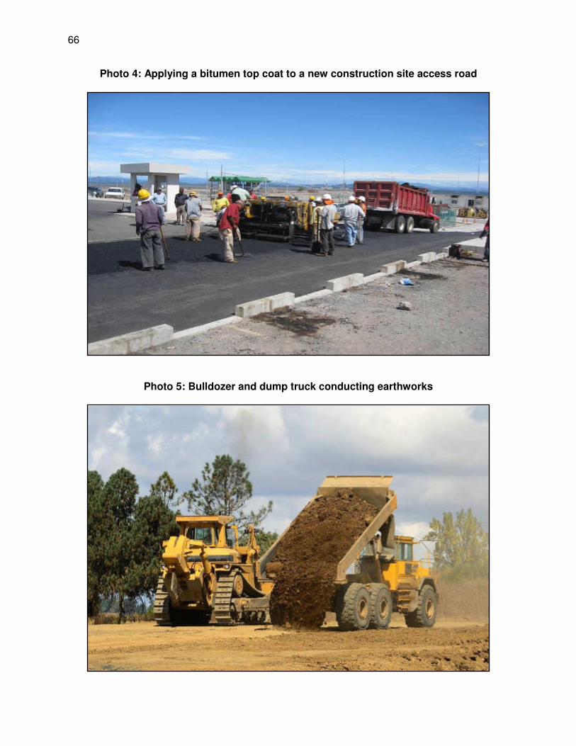
66
Photo 4: Applying a bitumen top coat to a new construction site access road
Photo 5: Bulldozer and dump truck conducting earthworks
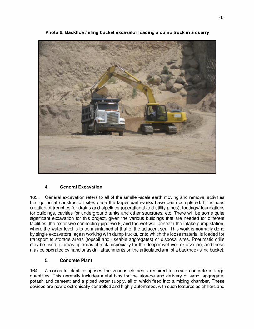
67
Photo 6: Backhoe / sling bucket excavator loading a dump truck in a quarry
4. General Excavation
163. General excavation refers to all of the smaller-scale earth moving and removal activities that go on at construction sites once the larger earthworks have been completed. It includes creation of trenches for drains and pipelines (operational and utility pipes), footings/ foundations for buildings, cavities for underground tanks and other structures, etc. There will be some quite significant excavation for this project, given the various buildings that are needed for different facilities, the extensive connecting pipe-work, and the wet-well beneath the intake pump station, where the water level is to be maintained at that of the adjacent sea. This work is normally done by single excavators, again working with dump trucks, onto which the loose material is loaded for transport to storage areas (topsoil and useable aggregates) or disposal sites. Pneumatic drills may be used to break up areas of rock, especially for the deeper wet-well excavation, and these may be operated by hand or as drill attachments on the articulated arm of a backhoe / sling bucket.
5. Concrete Plant
164. A concrete plant comprises the various elements required to create concrete in large quantities. This normally includes metal bins for the storage and delivery of sand, aggregate, potash and cement; and a piped water supply, all of which feed into a mixing chamber. These devices are now electronically controlled and highly automated, with such features as chillers and

68
heaters to provide accurate temperature control, and computer controlled delivery to ensure accurate mix compositions for different applications. 165. Concrete batching plant will be established on the site. Aggregate for the concrete will be obtained from the existing licensed crushers. No crusher plant will be established at the site. The concrete plant will probably operate throughout the middle of the construction period, when foundations and reinforced concrete (RC) buildings are created, and the intake and outfall structures.
6. Spoil Disposal
166. Spoil is soil, rock and other excavated material that is not suitable for re-use in the construction project and must therefore be disposed of. Contractors normally re-use as much material as can feasibly be reclaimed, because of the significant cost advantages over importation of fresh material from quarries. However, in this project there could be quite large quantities of spoil, if for example the surface sand that is present in some depth over the site, proves unsuitable for construction purposes because of its grain size, salt content, or other properties. All unusable material will be loaded into dump trucks and taken to disposal sites that are approved by the Client. These would normally include the nearest municipal landfill or dumpsite, any nearby construction areas requiring infill (if the material is suitable), or land on which the owner requires cavities filled, or the elevation raised prior to building.
Photo 7: Concrete production plant
7. Quarries and Borrow Pits
167. Even if a large amount of excavated material is suitable for re-use, inevitably most projects also need to import some construction materials. These are normally purchased from licenced quarries, where the material is excavated by the quarry operator and loaded into the contractor’s dump trucks and transported to site. Some material may also be dug locally by arrangement with landowners and after Client approval, creating what are known as “borrow pits”. Earlier studies

69
for the JKWSP mentioned an absence of sufficient hard stone and gravel for construction purposes on the Jaffna Peninsula as a potential issue, which could require transportation of materials from quarries on the mainland.
8. Concrete, Brick and Steel Structures
168. Creation of concrete structures will be one of the major construction activities for this project, as many of the RODP components will be fixed to concrete plinths and most will be housed in buildings with at least some concrete structural elements. Most such structures will be constructed from reinforced concrete (RC), where steel reinforcing rods and bars are placed and attached by hand to create an interior skeleton for the foundations, walls, columns, plinths, etc., and heavy-duty metal and timber/plywood formwork is bolted around the outside to build a mould into which pre-mixed concrete is poured. Once the concrete has set, the formwork is removed, and the concrete surface is finished by masons by hand if necessary. The process is repeated in the next adjacent part of the structure, which is gradually created in this way. 169. Some buildings, such as the pump station, guard house, workshop, etc., may be constructed from brick and breeze-block, in which case this work will be done mainly by hand, using standard house-building techniques. Footings and trenches for utility pipes and other services will first be excavated by backhoe / sling bucket, and stone and ready-mix concrete will be tipped in to create foundations. Bricks/breeze-blocks and mortar are then applied by masons by hand to create the walls, and plaster is applied to finish the interior surfaces. Wooden joists are fixed in place, also by hand, followed by tiles and other roofing materials. 170. Some buildings will be constructed from steel sheeting and others may have roofs, and/or walls of this material. Because of the weight of the steel, the sheets are normally put into position by cranes, and bolted into place by hand. Supporting structures may be steel girders which are again positioned by crane, or RC columns, created as described above. The interior fixtures and fittings in all buildings will be put in place and connected up by the relevant tradesmen - plumbers, electricians, carpenters, etc.
9. RODP Components
171. Most of the technical components of the reverse osmosis desalination system (intake pump station, intake screens, pre- and post-treatment systems and reverse osmosis racks) comprise a variety of pre-fabricated proprietary elements, which are installed on site as ready-made individual units. Such technology is not available in Sri Lanka so presumably most units will be purchased from abroad, delivered to the port or airport in Colombo, and transported to Jaffna on trucks. Units will then be offloaded on site for secure storage, and subsequently unpacked, lifted into position by crane, affixed to plinths or other installation points, and connected up to pipework and the electricity supply by hand. 172. Other less complex elements, such as chemical storage tanks, replacement screens, water pumps, etc. will probably also be purchased pre-assembled from abroad. Most of the supporting pipework, valves, electrical circuitry and other small scale site infrastructure will be purchased locally and assembled on site, but the main technical elements of the RODP will arrive ready-made and will involve installation, not assembly on site.

70
Photo 8: Steel reinforcing for building foundations and small structural columns
Photo 9: Steel reinforcing encased in steel and plywood formwork
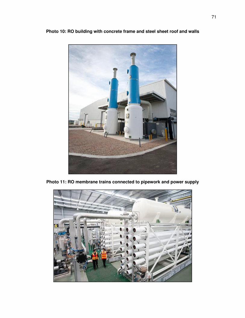
71
Photo 10: RO building with concrete frame and steel sheet roof and walls
Photo 11: RO membrane trains connected to pipework and power supply

72
173. The layout of the site and the positioning of the individual components and buildings will be determined during the design stage, but for illustrative purposes, Figure 12 shows an indicative layout provided by the FS consultant, and Photo 12 is an aerial view of an operating seawater RODP in Australia.
10. Other Site Infrastructure
174. Photos 10 and 12 show that there is a great deal of other smaller-scale infrastructure at an RODP site, including internal roads and areas of hard standing, water supply and drainage systems, wastewater collection and treatment system, security fences, signage, lighting, safety barriers, landscaping and planting, etc. Most of these elements will be constructed by small teams of skilled workers and labourers, working under the direction of supervisors and site engineers, with the aid of vehicles and machinery as appropriate. 175. Roads will be mainly bitumen-covered and constructed as described in Section IV.G, and if some areas are surfaced with concrete, this will be poured into pre-prepared boarded areas from a mobile mixer vehicle. Internal water, wastewater and drainage pipes will be fitted by plumbers and other skilled workers, and the external system will be installed in trenches, dug by backhoe / sling bucket. Fences, barriers, road lighting and signs will be constructed or assembled on site and installed in small concrete foundations, poured into cavities dug by backhoe / sling bucket. Landscaping will be designed and implemented by specialist contractors to enhance the appearance and ambience of the site and screen it from view if necessary. All planting will be maintained initially by the landscape contractor and then by the site operations contractor.
11. Sea Intake and Outfall
176. Lengths of HDPE pipe (estimated at around 600 mm in diameter) will be brought in on low-loader trucks and offloaded to storage by crane. Lengths will then be welded together on site to create the pipelines. The tender documents require the pipelines to be buried at 2 m depth, so trenching is the most likely approach. The alternative of directional drilling (where a sub-surface tunnel is drilled without disturbing the surface) is more complex and costly, and would probably only be used if the seabed to be undisturbed to protect the inhabiting marine life. 177. Works will be constructed with minimum disturbance to the beach. No pipes will be stored or assembled on the beach; these activities will be done on the adjacent land, between the beach and Mamune Road. The beach will be used as an access point to the ocean more for smaller items, and the pipes., but not for heavy machinery, which will be brought in on a barge from a port that has cranes and other facilities. Barge to aid the marine construction (intake and pipelines in sea bed) will loaded in Colombo or Galle and towed to the site and anchored. The precast intake tower and the equipment like dragline excavator, crane etc. as required for the construction work will be directly loaded on the barge and brought to the site via sea route. 178. A strip of 50 m wide land from the RODP into the sea through beach will be used for laying intake and outfall pipelines (trench size for each pipe will be around 2 m), for vehicle and equipment operation (excavators and crane to lay the pipeline) and also for accessing the sea. As the total pipeline length is only 2,300 m (1,300 m intake and 1,000 m outfall), total quantum of work is limited. Out of the this 1,300 m length (for both the pipes) will be laid in sea bed, about 100-150 m on the beach, and remaining on the scrub land between the beach and RODP site. The work site at beach will not be subjected to any improvements, and will be used as it is. If construction requires any stable ground, those works will be conducted in the adjacent land

73
beyond the beach. No activities such as– raising the height or strengthening the base with rock or gravel on the beach will be carried out. 179. Trenching will be done by bucket excavator, operating initially on the beach and adjacent land and then from a barge as the trench extends into the sea. The end of the intake will be at a depth of 10 - 11 m, so a drag line excavator, where a bucket is dragged along the bed from a crane (Photo 17), may be used for the deeper portions. Excavated material will be placed alongside the trench (on land and in the sea) so that it can be used to refill the trench once the pipe is installed. Where the seabed is composed of very loose sand the sides of the trench may be strengthened with temporary metal battens to prevent infill, in which case these are inserted and subsequently removed, by divers. 180. Once the trench is ready, floating buoys are attached to the pipeline, which is fed out to sea on a barge and guided into the trench by a crane on the barge and divers working below. Buoys are removed sequentially to allow the pipeline to sink into the trench, where it is held down with weights to prevent it from floating out. The trench is then backfilled by backhoe / sling bucket using the previously excavated material and the excess is allowed to redistribute naturally. 181. The intake is a precast concrete tower structure (a single pre-cast unit) and lifted into place on the seabed using a heavy-duty crane mounted on a barge or similar marine vessel. The pipe connections are then welded underwater by divers. The outfall terminates in a “duckbill” diffuser, comprising a series of smaller diameter pipes leading vertically up from the seabed, with a restricted opening to increase the ejection velocity. This will also be constructed on land and floated into position pre-attached to the end of the pipeline. 182. Appendix F presents the marine construction method for fixing of intake and outfall as prepared by Desalination Experts of the project as most likely approaches to be adopted.
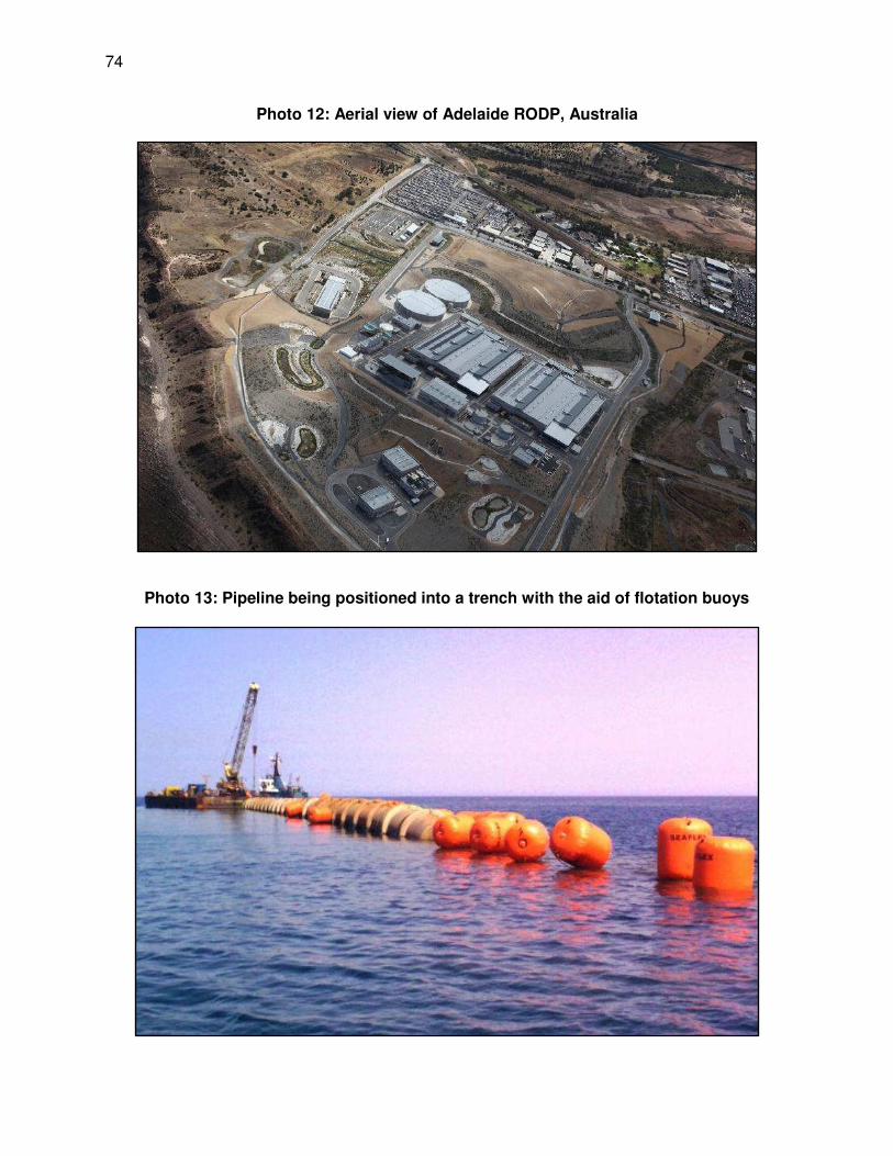
74
Photo 12: Aerial view of Adelaide RODP, Australia
Photo 13: Pipeline being positioned into a trench with the aid of flotation buoys

75
12. Potable Water Conveyance Pipeline
183. The pumping main pipeline (800 mm diameter DI pipe), 8 km in length, will be buried in a trench (approximately 1.3 m wide and 2 m deep) in the earthen shoulder of the existing roads within the roads Right of Way (RoW). Pipeline will originate from the clear water storage reservoir at RODP and will end at Puthukkadu Junction on Jaffna – Kandy Highway (A9), where it will be connected to a transmission main for conveyance to Jaffna for distribution to consumers. From the RODP, the pipeline will be buried along the new approach road to be constructed on southwest side of RODP (~700 m length ) and then along an internal road in Thalaiyadi that connects to Soranpattu – Thalaiyadi Road, B402, (~800 m length). The pipeline will then be laid along B402 up to its junction (Puthukkadu) with Jaffna – Kandy Highway, traversing a length of 6.5 km. As the entire transmission main is aligned along existing roads in earthen shoulder besides the tarmac, there are no sensitive environmental features or notable trees in the alignment. There may be a need to clear shrubs and bushes at one or two locations, but this is not significant. 184. Soranpattu – Thalaiyadi Road crosses Vadamarachchi lagoon. For about 1.5 km, lagoon is spread over both sides of the road. This road is formed on an earthen bund in the lagoon, except for a short length, where a bridge is provided for ensuring water flow through. For about 700 m (towards Jaffna-Kandy Road) there is adequate space along the tarmac and pipe will buried along the road without disturbing the lagoon area. In the remaining 800 m, where there is no space on the bund, pipeline will be laid over lagoon using concrete supports. There are mangroves in the lagoon, some of which are along the road bund, and therefore pipeline will be aligned sufficiently away from the road so that no mangroves are removed or damaged. 185. Trenches will be dug for pipeline using a backhoe / sling bucket digger. Excavated soil will be placed nearby, and the pipes will be placed in the trench by crane or using a small rig. Pipes will be joined by hand, after which sand from local quarries will be shovelled into the trench beneath and around the pipe for support and protection. Soil will then be replaced manually on top of the pipe and compacted by a vibrating compressor. This activity will generate 22,000 m3 of excavated soil, of which 17,000 m3 will be used to refill the trench, and the remaining 5,000 m3 of soil will need to be disposed off safely. 186. At the lagoon portion, 800 m length, pipeline will be laid on concrete support columns fixed in the lagoon bed. Alignment is on northwest of the road (see below figure), sufficiently away from the road bund where there are mangroves. Supports will be constructed mostly using precast elements. Hume pipes (diameter ~1 m) will be lowered in the lagoon using cranes, and pushed up to a depth where it meets hard surface (about 1-2 m below the lagoon bed), then premixed concrete brought from concrete batching plant will be tipped into the hume pipe using a concrete pump. Concreting will be continued up to the required height of the column. Hume pipe will act as form work, and there will be no need to remove this. Columns will be casted at distance of 20-25 m, and a cap will be fixed on the column top in order to provide a base for the pipeline. This kind of the construction allows the works to be done with minimal interference with the water body. Water will be disturbed, only during the placement of hume pipes, but given the smooth operation with cranes, even this disturbance will be minimal. Once the pipe is placed, concreting work will be within this pipe, and therefore there is no mixing of wet concrete with the water.
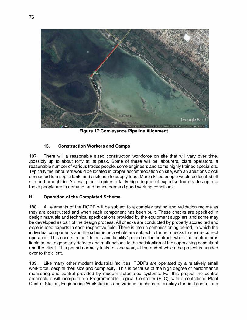
76
Figure 17:Conveyance Pipeline Alignment
13. Construction Workers and Camps
187. There will a reasonable sized construction workforce on site that will vary over time, .possibly up to about forty at its peak. Some of these will be labourers, plant operators, a reasonable number of various trades people, some engineers and some highly trained specialists. Typically the labourers would be located in proper accommodation on site, with an ablutions block connected to a septic tank, and a kitchen to supply food. More skilled people would be located off site and brought in. A desal plant requires a fairly high degree of expertise from trades up and these people are in demand, and hence demand good working conditions. H. Operation of the Completed Scheme
188. All elements of the RODP will be subject to a complex testing and validation regime as they are constructed and when each component has been built. These checks are specified in design manuals and technical specifications provided by the equipment suppliers and some may be developed as part of the design process. All checks are conducted by properly accredited and experienced experts in each respective field. There is then a commissioning period, in which the individual components and the scheme as a whole are subject to further checks to ensure correct operation. This occurs in the “defects and liability” period of the contract, when the contractor is liable to make good any defects and malfunctions to the satisfaction of the supervising consultant and the client. This period normally lasts for one year, at the end of which the project is handed over to the client. 189. Like many other modern industrial facilities, RODPs are operated by a relatively small workforce, despite their size and complexity. This is because of the high degree of performance monitoring and control provided by modern automated systems. For this project the control architecture will incorporate a Programmable Logical Controller (PLC), with a centralised Plant Control Station, Engineering Workstations and various touchscreen displays for field control and

77
annunciation (reports and warnings). Remote input/output racks will be distributed throughout the site, and the main control room will be located in the Administration Building. A tree-type communications system will integrate equipment, instruments and computers, allowing operating personnel a complete understanding of all process functions and equipment device status from the operator workstations as well as the control station. 190. The Feasibility Study estimates that 28 persons will be needed to operate the plant, comprising 4 managers, 4 operators, 4 maintenance technicians, 8 administrative/support workers, and 8 security guards, as shown in Table 13. The plant will be manned at all times, with a minimum of two operators and security staff present at night and during weekends and holidays, with other key staff on call if needed during such times.
Figure 18: Vertical intake tower with velocity cap recommended by Feasibility Study
Photo 14: Outfall pipe with array of duckbill diffusers, before installation (NB: those used in this project will be larger, with fewer diffusers)

78
Table 13: Projected staffing of the operating RODP (source: FS Final Report, 2015)
Position Number of staff
Plant Manager 1
Shift Operations Managers 3
Plant Operators 3
Instrumentation Technician 1
Electrician 1
Mechanics 2
Laboratory Technician 1
Storekeeper 1
Drivers 3
Security Guards 8
Labourers 3
Administrative Assistant 1
Total Plant Staff 28
191. The main operating functions of the workforce are as follows:
(i) Operation, monitoring and control of all treatment processes, equipment, instrumentation and facilities;
(ii) Collection and analysis of intake, treatment process and discharge water quality samples and instrumentation data38;
(iii) Preparation of reporting documentation on plant operations and performance (O&M reports; discharge compliance reports; reports to Government agencies);
(iv) Purchase and supply of all necessary consumables (chemicals, power, RO membrane elements, cartridge filters, tools and spare parts);
(v) Purchase and supply of auxiliary services and equipment (water supply and discharge, sewage and solid waste collection and disposal, site security, etc.).
192. An Annual Maintenance Plan will be prepared during the detailed design stage and the O&M staff will be responsible for its implementation. Related activities will involve: routine equipment inspections, repairs and upkeep; scheduled and emergency equipment maintenance; major equipment overhauls; buildings and grounds maintenance; and a spare parts inventory. 193. Certain elements of the plant will require regular replacement, in particular the cartridge filters upstream of the RO units, which need replacing every 2 months, and the reverse osmosis membranes, for which the replacement rate is approximately 20% per year. Various other parts of the plant require routine maintenance, including pumps and other equipment, and there will also be periodic checks and servicing of certain components. These activities will be the responsibility of the maintenance team, whose work will be planned and organised by an operations manager, reporting to the site manager. The contractor will also develop an emergency response plan, containing detailed instructions for all staff regarding actions to be taken to ensure personnel, public and environmental safety in the event of a serious malfunction, accidental damage or security violation.
38 Product water and discharge water samples will be analysed in specialised certified external laboratories; all other
process water samples will be analysed in-house at the plant laboratory

79
194. Operation and Maintenance of the conveyance main will be carried out by NWSDB. During the pipeline design life, it shall not require major repairs and should operate with little maintenance.
V. DESCRIPTION OF THE ENVIRONMENT
A. Overview
195. Baseline environmental profile of the study area has been primarily collected through field visits to the proposed sites, comprehensive literature survey, field studies & investigations and discussion with stakeholder agencies. 196. The study area is the area that could be affected, directly or indirectly, by the project during construction or operation. It includes the proposed site of the RODP and its immediate surroundings (Figure 1), the adjacent sea area, in which seawater intake and outfall pipelines and structures will be located and where the brine effluent will be discharged, the strip of coastal land between, across which the pipelines will run, and the proposed water transmission pipe alignment along Soranpattu to Thalaiyadi Road from RODP to Junction A9 on Jaffna – Kandy Road. It also includes offsite areas, such as haulage routes that will be used for access to and from the site, potential sources of construction materials, and local villages. The baseline study focused on the study area. The Vadamarachchi area and its administrative divisions are considered for social impacts, while environmental impacts are considered beyond the actual project footprint considering brine discharge and its spread in the sea, intake operation, dust noise from the construction and operations, etc., 197. The feasibility study for 24 MLD Seawater Reverse Osmosis Desalination Plant was completed in January 2015 (Appendix E2), and this, and the subsequent tender documents, provided the technical framework for the environmental assessment. EIA study was conducted from December 2015 till mid-2016 by LHI EIA Team with the support of the feasibility study consultants, technical experts of the NSWDB and its field staff, and ADB staff and consultants. 198. Reconnaissance visits. The EIA team made reconnaissance field visits between December 2015 and February 2016 to collect information, carry out discussions and conduct field studies to collect new data in the key fields of marine and terrestrial ecology and socio-economics of the local community. Team also consulted various line agency personnel, local communities and environmental groups. Available reports and literature relevant to the project were reviewed and socio-economic and environmental data available from local authorities were collected. 199. Baseline data includes secondary (existing) data, which was obtained from published and unpublished sources (e.g. books, papers, consultancy reports, etc.), and provided by local or national government and other stakeholders. Primary (new) data was obtained by conducting surveys in fields in which negative impacts might normally be anticipated from a development of this type, which included: terrestrial and marine ecology; water quality, air quality and noise; and socio-economics. Following field surveys are conducted using standard methods and equipment as described in the following sections.
(i) Bathymetric survey - 2 times: Mar – Apr 2016 (after NE monsoon), & Sep – Oct 2016 (Prior to NE monsoon)
(ii) Water level, current measurements & sea water analysis – 2 weeks x 3 times: Mar – Apr 2016 (Inter monsoon 1); Sep – Oct 2016 (Inter monsoon 2); Feb 2017 (during NE monsoon)
80
(iii) Marine Biological survey: March 2016 (iv) Ecological survey: Dec 2015 for RO plant site and Dec 2016 for transmission main
pipeline route (v) Sociological survey: March 2016 for the RO plant; & Dec 2016 -Jan 2017 for the
transmission main pipeline 200. Besides, the data collected for the engineering parts of the project yielded further primary data that was used to characterise certain other aspects of the local environment (topography, bathymetry, sediment, groundwater, etc.,). During the course of the study, EIA Team closely consulted various agencies for collation of data, information etc., important of which are as follows:
(i) Central Environmental Authority (CEA) head office & sub-regional office at Jaffna (ii) Jaffna and Kilinochchi District Secretariats (iii) Divisional Secretary, Vadamarachchi East Divisional Secretariat (iv) Urban Development Authority, Northern Province Office at Jaffna (v) Department of Fisheries, district office at Jaffna (vi) Thalaiyadi Fishermen’s Co-operative Society. (vii) Village Development Society, Thalaiyadi (viii) Community leaders and prominent persons in project area
201. Field Investigation Report of August 2016 prepared by LHI is appended at Appendix G. B. Physical Conditions
1. Climate and Rainfall
202. The Jaffna Peninsula is in Sri Lanka’s dry zone, which covers much of the north, east and south-east of the country, where average rainfall is between 1000 and 1250 mm per year and air temperatures are 26.5 - 28.5 °C.39 Jaffna is not in the most arid areas in the north-west and south-east, but temperatures are still among the highest in the country, with daily averages ranging from 26.3 °C in December/January to 30.9 °C in May, with an annual average of 28.2 °C.40 203. Climate of Sri Lanka is influenced by its topographic features (mountains in central and south, and flat landscape in the rest) and southwest and northeast monsoons. The annual climate is broadly classified into 4 seasons: (i) First inter-monsoon, March – April, (ii) southwest monsoon, May – September, (iii) second inter-monsoon, October – November, and (iv) northeast monsoon, December – February. 204. Climate in the north is strongly influenced by the north-east monsoon, which brings higher winds and rainfall between October and February, and much lower rainfall over the rest of the year. Data from the Jaffna rainfall gauging station shows that between 2006 and 2014, average rainfall was <80 mm per month between January and September and >200 mm per month between October and December, with a peak of 380 mm in November. Figure 19 also shows the wide annual variations that can occur, from a minimum of 870 mm in 2006 to a maximum of 1800 mm in 2008.
39 Department of Meteorology, Government of Sri Lanka: http://www.meteo.gov.lk/index.php?option=com_content&view=article&id=94&Itemid=310&lang=en 40 World Meteorological Organisation: http://worldweather.wmo.int/en/city.html?cityId=341

81
2. Air Quality
205. Air quality in Sri Lanka has been measured by CEA since 1998, and has focused mainly on the capital, where the permanent monitoring station at Colombo Fort has revealed levels of particulates (PM10) that are consistently above the WHO guideline of 50 µg/mm3, although there is a decreasing trend.41 Particulates are mainly attributable to traffic emissions, especially from the growing numbers of motor cycles and auto-rickshaws. A mobile ambient air quality monitoring station has provided some data from other locations, but not yet from Jaffna. The nearest ambient air quality monitoring stations is located at Anuradhapura, 100 km south of Kilinochchi (Figure 1). No ambient air quality data therefore is available for the project area or the nearby location. 206. Air quality at the project site would probably be very high for most of the time as the area is uninhabited and often subject to sea breezes, and the only possible contaminant might be Aeolian sand, blown when winds are higher. There are no other sources of air pollution such as industries, and vehicular traffic is also very limited. Nearest village is Thalaiyadi, 750 m from the plant site, and the air pollution source is fire wood used for cooking and other daily chores . Prior to start of construction, the contractor will establish baseline ambient air quality of project site and in the surrounding area (Thalaiyadi village). This is included in the Environmental Monitoring Plan.
Figure 19: Average annual (A) and monthly (B) rainfall in Jaffna, 2006-14
207. Noise. Background noise levels in the area were found to be very low, varying in the range of 40 – 54 dB (A) (see Table 14). There are no notable man-made noise sources. Ambient noise levels (day time) were measured at 10 locations (see map) using hand held sound level meter.
41 Central Environment Authority: http://www.cea.lk/web/index.php/en/air-quality

82
The existing noise levels are mainly attributed to the noise generated from waves breaking on the shore, the rattling of leaves of trees by the wind and the occasional screech of birds passing and roosting in the area. Traffic generated noise is occasional, predominantly from three wheelers and motor bicycles. Noise levels along the road and coast are higher than at plant site, which is located quite inside with no noise at all.
Table 14: Ambient Day time Noise Level at Project Site
Location Noise level dB(A) Location Noise level dB(A)
P1 50 P6 45
P2 53 P7 40
P3 53 P8 42
P4 54 P9 43
P5 50 P10 42
3. Topography and Soils
208. Jaffna District adjoins Kilinochchi District on the mainland, and consists of the peninsula and seven inhabited islands, with a total land area (including inland lagoons) of 1,012 km2. The topography of the peninsula is low and relatively flat, with a maximum height of + 11 m, in the western central area near Tellipallai. The peninsula was covered by the sea up to the Miocene epoch and limestone is the dominant substratum, in an area of entirely coastal landforms, comprising floodplains, coastal plains, low sand dunes and beaches. 208. Soils are a mixture of marine deposits and sediments formed by the influence of wind and waves on the limestone. In the central area there are around 60,000 ha of well-drained and highly productive calcic Red-Yellow Latosol and similar types; near the coast are around 26,000 ha of alkaline saline soil and unconsolidated Regosol; and around the seasonal river Valukkai Aru area

83
near Tellipallai are approximately 10,000 ha of alluvial sediments. Soil depth across the peninsula varies from 900 - 1500 mm.42 209. The RODP site lies on the narrow strip of land, around 1.5 km wide, on the northern side of Vadamarachchi Lagoon, between the lagoon and the Bay of Bengal. The narrow beach shelves quickly down to the sea, and a topographic survey for this study (Figure 20) shows that around the project site the land is relatively flat and low-lying, varying between 2.7 - 3.5 m above mean sea level (AMSL). The area was originally a sand bar, and as noted above, the soils are sandy, white and unconsolidated, although reasonably productive, judging from the vegetation that is present. 210. Topography of the pipeline alignment along the Soranpattu – Thalaiyadi Road is flat and gently slopes towards the Vadamarachchi lagoon, and the sea on the east side. Ground level varies from about 5-6 m AMSL near Jaffna-Kandy Road junction to about 2-3 AMSL near village Thalaiyadi. Alignment crosses Vadamarachchi lagoon.
Figure 20: Topography of the project site (C) and the surrounding area (B)
4. Geology
211. The limestone layer that is so prominent in the north of Sri Lanka and so important because of its water-bearing characteristics, probably originated from coral reefs during the
42 Jaffna District Secretariat: http://www.jaffna.dist.gov.lk/index.php?option=com_content&view=article&id=98&Itemid=221&lang=en
84
Miocene period and earlier, in the major sedimentary basin that was present in the north-western coastal belt at that time. The limestone overlies high-grade Precambrian crystalline metamorphic rocks, although in some places it is underlain by sedimentary layers of upper Jurassic age. In Jaffna these formations are around 250 m thick and comprise Mannar sandstone at the base, 50-90 m of limestone in the middle, and a thin, discontinuous surface cover. The limestone is extensively exposed in the west of the peninsula, forming the land surface around Chunnakam north of Jaffna city, in a small area west of Point Pedro and on the islands off the west coast.43 212. Jaffna limestone is poorly bedded and generally flat, except in some areas where it shows a slight dip to the west. It is massive in places but some layers are richly fossiliferous, forming a honeycombed structure. The ready solubility of the limestone produces a number of underground solution caverns, which contain the main groundwater reserves on the island.44 213. The surface cover of unconsolidated deposits is the youngest of the geological layers and produces the sandy soil that is present over much of the peninsula. The central Latosols around Chunnakam reach a maximum depth of 3 m and are red in colour from a haematite coating. In Chavakachcheri-Palai south-west of Vadamarachchi Lagoon the deposits are yellow and brown, fine to medium grained, with a maximum thickness of only 15 mm. In contrast around the project site north-east of Vadamarachchi Lagoon, the sediment is of more recent origin and forms much deeper beds, which reach 8 - 17 m in places. The sand is also quite mobile and forms dunes a few kilometres north of the site, around Manalkadu near Point Pedro.
5. Surface Water and Drainage
214. The flat terrain, porous geology and highly seasonal rainfall in which 70% of the rain occurs in a three-month period (see Figure 19) all combine to prevent the development of permanent rivers on the Jaffna Peninsula. There are two seasonal rivers (Thondaman Aru, west of Point Pedro; and Valuki Aru, west of Jaffna City), both around 10 km in length, but these and the few other seasonal streams only carry water in the rainy season. The topography also precludes any development of large-scale reservoirs as there are no suitable landforms to accommodate large dams and no significant depressions in which large quantities of river or rainwater could be held. Some natural depressions have been enhanced with earth bunds and removal of soil to increase the depth, and these and other low-lying areas form a series of over 600 “tanks” or “ponds” in which individual small quantities of rainwater are retained during and after the rainy season for use in agriculture. 215. The ponds aid drainage and irrigation in conjunction with a cascade system of artificial ditches (small drainage canals) created by the Dutch who colonised Sri Lanka in the 17th and 18th centuries. The canals and ponds have been de-silted and maintained in order to detain and divert monsoon rains to irrigate fields and recharge groundwater. During heavy rainfall the drainage channels first fill paddy fields and village ponds (normally sited towards the centre of the fields) in sequence. Water then spills over and flows down to fill the next lower pond and so on down the cascade, ultimately draining into the sea or one of the lagoons. The Provincial Irrigation Department has built ring spill structures at road crossings to impede this drainage process and further promote groundwater recharge. 43 Mikunthan T, Vithanage M, Pathmarajah S, Arasalingam S, Ariyaratne R and Manthrithilake H (2013):
Hydrogeochemical characterization of Jaffna’s aquifer systems in Sri Lanka. International Water Management Institute, Colombo, 69 pp (http://www.iwmi.cgiar.org/Publications/Books/PDF/jaffna_report-1.pdf?galog=no)
44 Cooray P G (1984) An introduction to the Geology of Sri Lanka, 2nd revised edition. National Museums of Sri Lanka, pp 120-260.
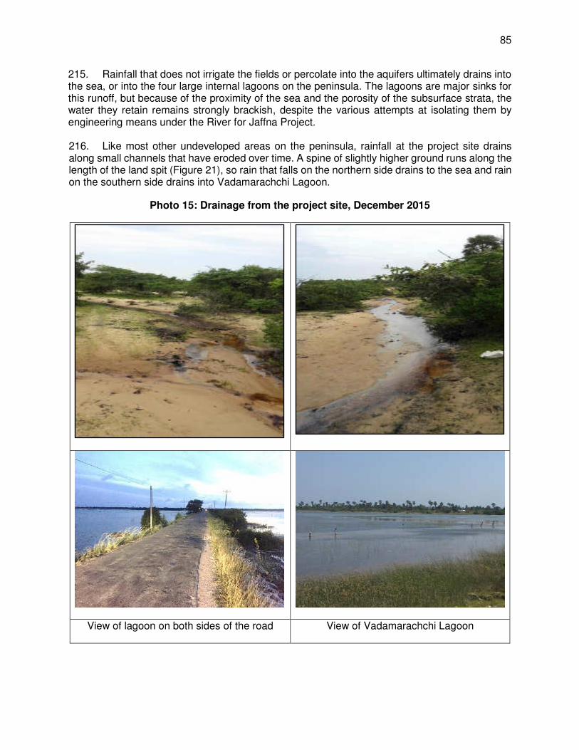
85
215. Rainfall that does not irrigate the fields or percolate into the aquifers ultimately drains into the sea, or into the four large internal lagoons on the peninsula. The lagoons are major sinks for this runoff, but because of the proximity of the sea and the porosity of the subsurface strata, the water they retain remains strongly brackish, despite the various attempts at isolating them by engineering means under the River for Jaffna Project. 216. Like most other undeveloped areas on the peninsula, rainfall at the project site drains along small channels that have eroded over time. A spine of slightly higher ground runs along the length of the land spit (Figure 21), so rain that falls on the northern side drains to the sea and rain on the southern side drains into Vadamarachchi Lagoon.
Photo 15: Drainage from the project site, December 2015
View of lagoon on both sides of the road View of Vadamarachchi Lagoon

86
Figure 21: Topography, surface water and drainage around the project site
6. Groundwater
217. The absence of perennial surface water reserves means that groundwater is the only source for domestic supply on the Jaffna Peninsula, and is also used in agriculture in the long dry season. There are both karstic45 and sand aquifers on the peninsula, but the limestone deposits are larger, with far greater storage capacity and are therefore the main source. Figure 22 shows how the aquifer is recharged directly by rainfall percolating down through fissures in the limestone, and indirectly by infiltration from the ephemeral rivers and streams, and the ponds, drainage channels and other water retention and distribution structures. Seawater also enters through fissures in the seabed, and is present in the aquifers as a denser layer below the mound-shaped lenses of freshwater floating above. 218. There are four main aquifers on the peninsula, below each of the four main land masses: Chunnakam aquifer, north of Jaffna city; Kayts on the eponymous island; Thaemaradchi between Jaffna Lagoon and Vadamarachchi Lagoon; and Vadamarachchi aquifer alongside the north-eastern coast. Freshwater lenses are thicker towards the centre of each aquifer and thinner in coastal areas where the deeper water is brackish, so potable supply is more reliable inland. All of the aquifers are replenished during the rains in November and December and are then gradually diminished by abstraction and natural subsurface flow throughout the rest of the year.46 Annual recharge for Jaffna has been calculated at between 10-20 x 107 m3, of which approximately half is used for domestic supply and agriculture and the other half drains into the sea during the monsoon.47
45 Karst: porous limestone containing voids created by dissolution 46 Panabokke C R and Perera A P G R L (2005): Groundwater resources of Sri Lanka. Water Resources Board,
Colombo (http://obeysekera.net/tsunami/documents/Panabokke_Perera_2005_Sri_Lanka.pdf) 47 Balendran V S, Sirimanne C H I and Arumugam S (1968): Groundwater resources of Jaffna Peninsula. Water
Resources Board, Colombo
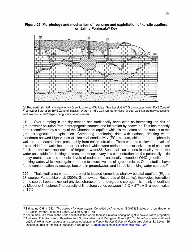
87
Figure 22: Morphology and mechanism of recharge and exploitation of karstic aquifers on Jaffna Peninsula48 Key
(a) Red earth, (b) Jaffna limestone, (c) Granitic gneiss, MSL Mean Sea Level, GWT Groundwater Level, FWZ Zone of Freshwater Saturation, BWZ Zone of Brackish Water, (1) dry well, (2) “bottomless” or tidal well, (3) ordinary successful well, (4) Keerimalai49-type spring, (5) solution cavern 219. Over-pumping in the dry season has traditionally been cited as increasing the risk of groundwater pollution from anthropogenic sources and infiltration by seawater. This has recently been reconfirmed by a study of the Chunnakam aquifer, which is the Jaffna source subject to the greatest agricultural exploitation. Comparing monitoring data with national drinking water standards showed high values of electrical conductivity (EC), sodium, chloride and sulphate in wells in the coastal area, presumably from saline intrusion. There were also elevated levels of nitrate-N in farm wells located farther inland, which were attributed to excessive use of chemical fertilizers and over-application of irrigation water38. Seasonal fluctuations in quality made the water unsuitable for drinking at times, and despite very low concentrations of the potentially toxic heavy metals lead and arsenic, levels of cadmium occasionally exceeded WHO guidelines for drinking water, which was again attributed to excessive use of agrochemicals. Other studies have found contamination by sewage bacteria in groundwater, and in public drinking water sources.50 220. Thalaiyadi area where the project is located comprises shallow coastal aquifers (Figure 23, source: Panabokke et al. (2005), Groundwater Resources of Sri Lanka). Geological formation of the sub-soil bears excellent physical character for underground storage. It is mainly underlined by Miocene/ limestone. The porosity of limestone varies between 4.5 % ~ 27% with a mean value of 15%.
48 Sirimanne C H I (1952): The geology for water supply. Compiled by Arumugam S (1974) Studies on groundwater in
Sri Lanka. Water Resources Board, Colombo, pp 31-58 49 Keerimmalai is a town on the north coast of Jaffna where there is a mineral spring thought to have curative properties 50 Arulnesan C A, Kamsan S, Rajeshkannan N, Sivapalan K and Murugananthan K (2015): Microbial contamination of
public drinking water sources and associated factors in Kopay Medical Officer of Health area Jaffna, Sri Lanka. Sri Lankan Journal of Infectious Diseases, 5 (2), pp 64-72 (http://repo.jfn.ac.lk/med/handle/701/1225)
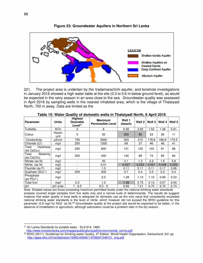
88
Figure 23: Groundwater Aquifers in Northern Sri Lanka
221. The project area is underlain by the Vadamarachchi aquifer, and borehole investigations in January 2016 showed a high water table at the site (0.3 to 0.6 m below ground level), as would be expected in the rainy season in an area close to the sea. Groundwater quality was assessed in April 2016 by sampling wells in the nearest inhabited area, which is the village of Thalaiyadi North, 750 m away. Data are limited as the
Table 15: Water Quality of domestic wells in Thalaiyadi North, 6 April 2016
Parameter Units Highest
Desirable Level51
Maximum Permissible Level
Well 1 (beach)
Well 2 Well 3 Well 4 Well 5
Turbidity NTU 2 8 6.92 2.83 1.52 1.36 0.61
Colour Hazen
unit 5 30 289 86 23 26 11
Conductivity µS/cm 750 3500 303 215 178.8 186.6 170.5 Chloride (Cl-) mg/l 200 1200 69 37 46 46 41 Total Hardness (as CaCo3)
mg/l 250 600 131 125 103 91 86
Total Alkalinity (as CaCO3)
mg/l 200 400 140 88 74 65 84
Nitrate (as N) mg/l - 45 3.1 1.3 2.2 1.5 0.8 Nitrite (as N) mg/l - 0.01 0.027 0.023 0.021 0.048 0.025 Fluoride (as F) mg/l - 1.5 0.11 0.11 0.11 0.17 0.06 Sulphate (SO4
2-) mg/l 200 400 0.7 0.4 0.5 0.2 0.4 Phosphate (as PO4
3-) mg/l - 2.0 1.28 1.12 1.15 0.99 0.03
Total Iron mg/l 0.3 1.0 1.49 0.73 0.13 0.07 0.04 pH pH units 7 - 8.5 6.5 - 9 6.99 7.21 6.75 6.70 6.73
Note: Shaded values are those exceeding maximum permitted levels under the national drinking water standards analysis covered single samples from five wells only and a narrow suite of determinands. The results do suggest however that water quality in local wells is adequate for domestic use as the only value that consistently exceeded national drinking water standards is the level of nitrite, which however did not exceed the WHO guideline for this parameter (0.9 mg/l for NO2- as N).52 Groundwater quality at the project site would be expected to be better, in the absence of inhabitation or agriculture, although salinization could be a problem later in the dry season.
51 Sri Lanka Standards for potable water - SLS 614, 1983: http://www.investsrilanka.com/images/publications/pdf/environmental_norms.pdf 52 WHO (2011): Guidelines for Drinking-water Quality, 4th Edition. World Health Organisation, Switzerland, 541 pp http://apps.who.int/iris/bitstream/10665/44584/1/9789241548151_eng.pdf

89
7. Coastal Bathymetry
222. The bathymetry of the coastal zone adjacent to the project site (where intake and outfall pipelines will be located) was surveyed in March-April 2016 and again in September-October 2016. A total area of 1 sq. km (0.5 km wide x 2 km length into the sea from beach), covering about 250 m on both sides of the intake and outfall sites. Survey conducted using echo sounder operated from a boat travelling along transect lines perpendicular to the coast, at 20 m intervals. Navigation was by HYDROpro software coupled with Differential Global Positioning System (DGPS), with some cross-survey lines to confirm precision of soundings. Topographic surveys were conducted in shallow water and up to 50 m inland by standard levelling techniques. Height and depth data were integrated and plotted by AutoCAD software, and the results, showing 1 m depth contours, are presented in Figure 24.
Photo 16: Bathymetric (top) and Topographic Survey (bottom)
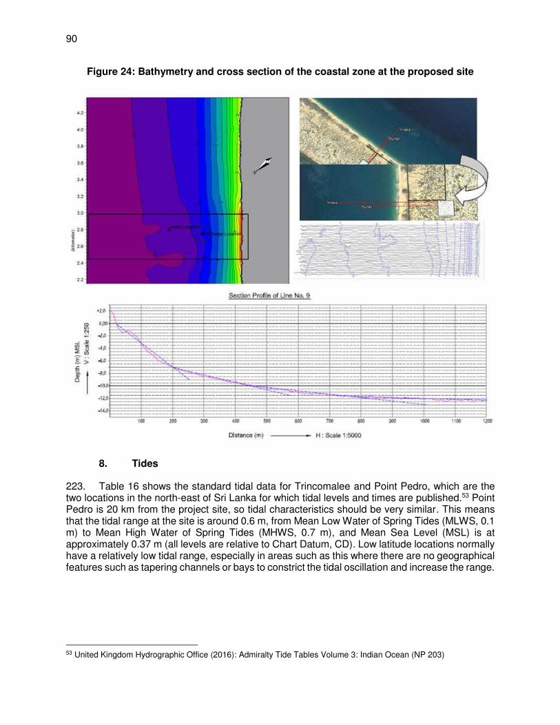
90
Figure 24: Bathymetry and cross section of the coastal zone at the proposed site
8. Tides
223. Table 16 shows the standard tidal data for Trincomalee and Point Pedro, which are the two locations in the north-east of Sri Lanka for which tidal levels and times are published.53 Point Pedro is 20 km from the project site, so tidal characteristics should be very similar. This means that the tidal range at the site is around 0.6 m, from Mean Low Water of Spring Tides (MLWS, 0.1 m) to Mean High Water of Spring Tides (MHWS, 0.7 m), and Mean Sea Level (MSL) is at approximately 0.37 m (all levels are relative to Chart Datum, CD). Low latitude locations normally have a relatively low tidal range, especially in areas such as this where there are no geographical features such as tapering channels or bays to constrict the tidal oscillation and increase the range.
53 United Kingdom Hydrographic Office (2016): Admiralty Tide Tables Volume 3: Indian Ocean (NP 203)
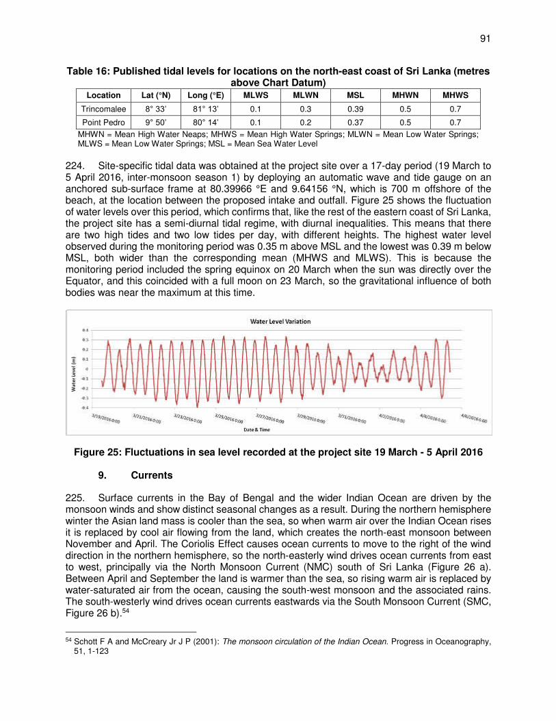
91
Table 16: Published tidal levels for locations on the north-east coast of Sri Lanka (metres above Chart Datum)
Location Lat (°N) Long (°E) MLWS MLWN MSL MHWN MHWS
Trincomalee 8° 33’ 81° 13’ 0.1 0.3 0.39 0.5 0.7
Point Pedro 9° 50’ 80° 14’ 0.1 0.2 0.37 0.5 0.7
MHWN = Mean High Water Neaps; MHWS = Mean High Water Springs; MLWN = Mean Low Water Springs; MLWS = Mean Low Water Springs; MSL = Mean Sea Water Level
224. Site-specific tidal data was obtained at the project site over a 17-day period (19 March to 5 April 2016, inter-monsoon season 1) by deploying an automatic wave and tide gauge on an anchored sub-surface frame at 80.39966 °E and 9.64156 °N, which is 700 m offshore of the beach, at the location between the proposed intake and outfall. Figure 25 shows the fluctuation of water levels over this period, which confirms that, like the rest of the eastern coast of Sri Lanka, the project site has a semi-diurnal tidal regime, with diurnal inequalities. This means that there are two high tides and two low tides per day, with different heights. The highest water level observed during the monitoring period was 0.35 m above MSL and the lowest was 0.39 m below MSL, both wider than the corresponding mean (MHWS and MLWS). This is because the monitoring period included the spring equinox on 20 March when the sun was directly over the Equator, and this coincided with a full moon on 23 March, so the gravitational influence of both bodies was near the maximum at this time.
Figure 25: Fluctuations in sea level recorded at the project site 19 March - 5 April 2016
9. Currents
225. Surface currents in the Bay of Bengal and the wider Indian Ocean are driven by the monsoon winds and show distinct seasonal changes as a result. During the northern hemisphere winter the Asian land mass is cooler than the sea, so when warm air over the Indian Ocean rises it is replaced by cool air flowing from the land, which creates the north-east monsoon between November and April. The Coriolis Effect causes ocean currents to move to the right of the wind direction in the northern hemisphere, so the north-easterly wind drives ocean currents from east to west, principally via the North Monsoon Current (NMC) south of Sri Lanka (Figure 26 a). Between April and September the land is warmer than the sea, so rising warm air is replaced by water-saturated air from the ocean, causing the south-west monsoon and the associated rains. The south-westerly wind drives ocean currents eastwards via the South Monsoon Current (SMC, Figure 26 b).54
54 Schott F A and McCreary Jr J P (2001): The monsoon circulation of the Indian Ocean. Progress in Oceanography,
51, 1-123
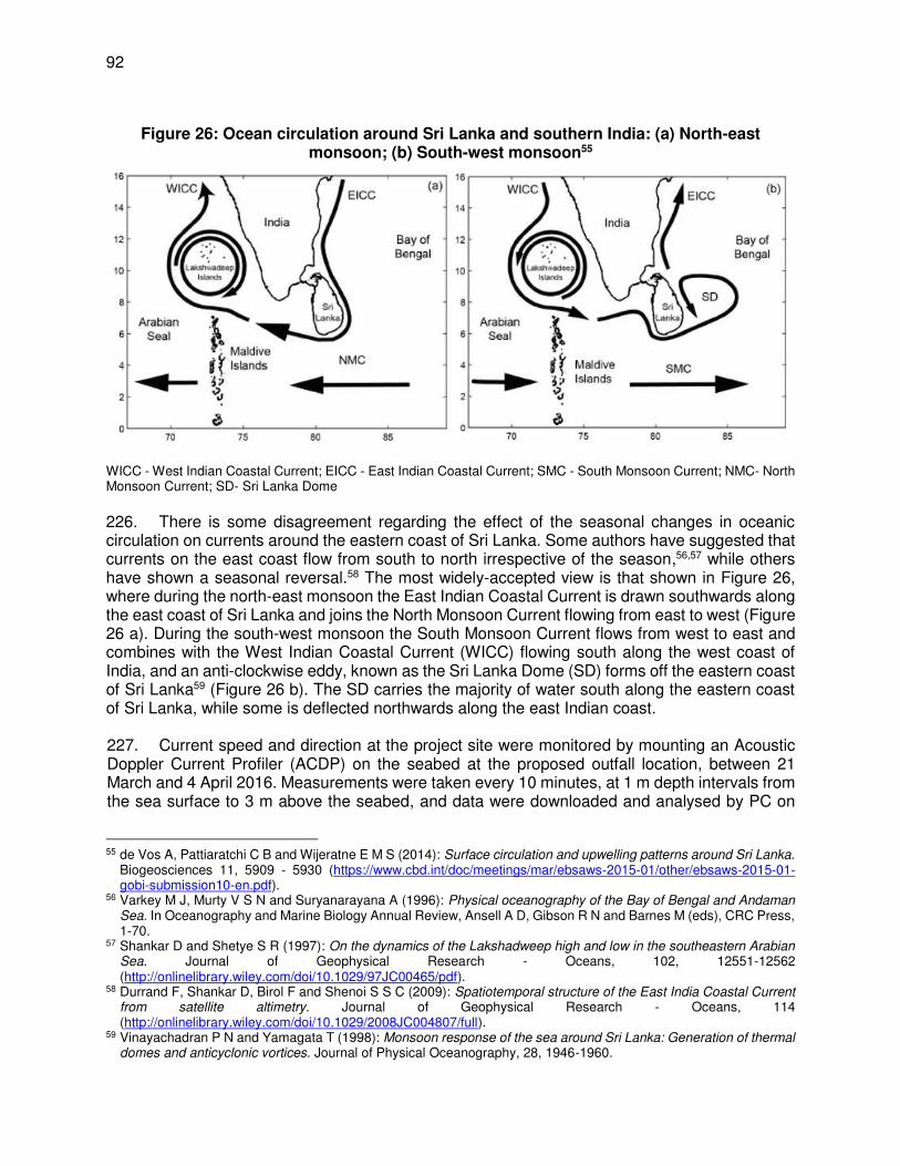
92
Figure 26: Ocean circulation around Sri Lanka and southern India: (a) North-east
monsoon; (b) South-west monsoon55
WICC - West Indian Coastal Current; EICC - East Indian Coastal Current; SMC - South Monsoon Current; NMC- North Monsoon Current; SD- Sri Lanka Dome 226. There is some disagreement regarding the effect of the seasonal changes in oceanic circulation on currents around the eastern coast of Sri Lanka. Some authors have suggested that currents on the east coast flow from south to north irrespective of the season,56,57 while others have shown a seasonal reversal.58 The most widely-accepted view is that shown in Figure 26, where during the north-east monsoon the East Indian Coastal Current is drawn southwards along the east coast of Sri Lanka and joins the North Monsoon Current flowing from east to west (Figure 26 a). During the south-west monsoon the South Monsoon Current flows from west to east and combines with the West Indian Coastal Current (WICC) flowing south along the west coast of India, and an anti-clockwise eddy, known as the Sri Lanka Dome (SD) forms off the eastern coast of Sri Lanka59 (Figure 26 b). The SD carries the majority of water south along the eastern coast of Sri Lanka, while some is deflected northwards along the east Indian coast. 227. Current speed and direction at the project site were monitored by mounting an Acoustic Doppler Current Profiler (ACDP) on the seabed at the proposed outfall location, between 21 March and 4 April 2016. Measurements were taken every 10 minutes, at 1 m depth intervals from the sea surface to 3 m above the seabed, and data were downloaded and analysed by PC on
55 de Vos A, Pattiaratchi C B and Wijeratne E M S (2014): Surface circulation and upwelling patterns around Sri Lanka.
Biogeosciences 11, 5909 - 5930 (https://www.cbd.int/doc/meetings/mar/ebsaws-2015-01/other/ebsaws-2015-01-gobi-submission10-en.pdf).
56 Varkey M J, Murty V S N and Suryanarayana A (1996): Physical oceanography of the Bay of Bengal and Andaman Sea. In Oceanography and Marine Biology Annual Review, Ansell A D, Gibson R N and Barnes M (eds), CRC Press, 1-70.
57 Shankar D and Shetye S R (1997): On the dynamics of the Lakshadweep high and low in the southeastern Arabian Sea. Journal of Geophysical Research - Oceans, 102, 12551-12562 (http://onlinelibrary.wiley.com/doi/10.1029/97JC00465/pdf).
58 Durrand F, Shankar D, Birol F and Shenoi S S C (2009): Spatiotemporal structure of the East India Coastal Current from satellite altimetry. Journal of Geophysical Research - Oceans, 114 (http://onlinelibrary.wiley.com/doi/10.1029/2008JC004807/full).
59 Vinayachadran P N and Yamagata T (1998): Monsoon response of the sea around Sri Lanka: Generation of thermal domes and anticyclonic vortices. Journal of Physical Oceanography, 28, 1946-1960.
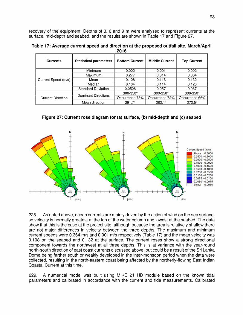
93
recovery of the equipment. Depths of 3, 6 and 9 m were analysed to represent currents at the surface, mid-depth and seabed, and the results are shown in Table 17 and Figure 27.
Table 17: Average current speed and direction at the proposed outfall site, March/April 2016
Currents Statistical parameters Bottom Current Middle Current Top Current
Current Speed (m/s)
Minimum 0.002 0.001 0.002 Maximum 0.277 0.314 0.364
Mean 0.108 0.118 0.132 Median 0.104 0.114 0.126
Standard Deviation 0.0528 0.057 0.067
Current Direction Dominant Directions
300-350° 300-350° 300-350° Occurrence 73% Occurrence 72% Occurrence 66%
Mean direction 291.7 283.1 272.5
Figure 27: Current rose diagram for (a) surface, (b) mid-depth and (c) seabed
228. As noted above, ocean currents are mainly driven by the action of wind on the sea surface, so velocity is normally greatest at the top of the water column and lowest at the seabed. The data show that this is the case at the project site, although because the area is relatively shallow there are not major differences in velocity between the three depths. The maximum and minimum current speeds were 0.364 m/s and 0.001 m/s respectively (Table 17) and the mean velocity was 0.108 on the seabed and 0.132 at the surface. The current roses show a strong directional component towards the northwest at all three depths. This is at variance with the year-round north-south direction of east coast currents discussed above, but could be a result of the Sri Lanka Dome being farther south or weakly developed in the inter-monsoon period when the data were collected, resulting in the north-eastern coast being affected by the northerly-flowing East Indian Coastal Current at this time. 229. A numerical model was built using MIKE 21 HD module based on the known tidal parameters and calibrated in accordance with the current and tide measurements. Calibrated

94
model was then used to simulate the current field of the project site and its adjacent water area. The details of the hydraulic circulation and current field are shown in the Figure below
Figure 28: Hydraulic Circulation and Current Field of the Proposed Project Area
10. Waves
230. As well as environmental and engineering studies, the project also included numerical modelling to predict the dispersion of brine effluent to assist in outfall design and the assessment of impacts (see Section III.D.2). These studies normally require data on wave climate collected over at least 5-10 years, and such data are not available for this location. An alternative that is often used in modelling studies is data from the 2D Global Spectral Wind and Wave Models used by the UK Meteorological Office (UKMO) to forecast sea states throughout the world’s oceans. The model assimilates wave measurements from the radar altimeter on the European Remote Sensing Satellite ERS-2 and spectral and statistical outputs (including wave height, period and direction; and wind speed and direction) are available for most sea areas. 231. Data were obtained from the UKMO covering the period January 2010 to July 2015 at 6-hourly intervals for the nearest location to the project site, which is 93 km offshore in an easterly direction (coordinates 9° 36.54’ N, 81° 12.66’ E). To compensate for the much shallower depth at the project site the MIKE 21 spectral wave model was used to conduct wave transformation and simulate the inshore wave climate. Figure 29 is the resulting wave rose showing the annual average direction, magnitude and percentage occurrence of various wave heights.

95
Figure 29: Wave rose showing height, direction and percentage occurrence of near shore wave heights - annual distribution
232. The project area is located on the north-eastern coast of Sri Lanka, which experiences high winds and sea swells from the north-easterly direction, especially during the north-east monsoon between November and April. The data reflect these factors, showing that waves with the greatest height (> 1 m) approach from the north-east, with a percentage occurrence of 41%. It should be noted however that average wave height is 0.25 m and the maximum height 1.75 m, so this is not an area exposed to severe wave action.
11. Seawater Quality
233. The quality of seawater at the project site was investigated by collecting water samples at three stations parallel with the coastline approximately 0.5 km apart, in the vicinity of the proposed intake and outfall locations. Samples were taken at the surface, mid depth and seabed at one station and at mid depth at the other two stations, using a Niskin sub-surface sampling bottle. Samples were placed in sealed glass bottles and sterilized plastic bottles for microbial analysis, and transported to the laboratory at 4°C in chilled containers. Analyses were conducted by a government accredited laboratory, following standard methods for analysis of water and wastewater.60
60 Rice E W, Baird, R B, Eaton, A D and Clesceri L S (2012): Standard Methods for the Examination of Water and
Wastewater, 22nd Edition. American Public Health Association, American Water Works Association.

96
234. A very wide range of determinants were analysed, 74 in total, including all of the standard physical and chemical parameters, plus 12 heavy metals and 35 pesticide residues. The results are provided in Appendix H and these indicate that seawater quality at the project site is good, with low values of suspended solids (< 2 mg/l) and organic matter (< 5 mg/l 5-day BoD), and no evidence of pollution by oil and grease, heavy metals, faecal bacteria or pesticides. This reflects the remote nature of the project site and the relatively low population; and the lack of pollutants is because of the absence of industry or intensive agriculture. The results also suggest a well-mixed and quite dynamic marine environment, with few differences in water quality throughout the water column. C. Biological Conditions – RODP Plant site
1. Terrestrial Ecology
235. Sri Lanka contains some very different climatic zones, altitudes from sea level to 2,524 m, widely diverging topographic features, 103 major rivers, 1,620 km of coastline, and irrigated agriculture in which storage structures function as artificial wetlands. Because of these and other features, Sri Lanka has a wide array of habitats and ecosystems and a resulting species diversity that is considered to be the richest per unit area in all of Asia.61 20 million years of island geography, following separation from India in the Miocene, has enhanced this diversity by fostering an exceptional degree of endemism, in which for example 43% of the vertebrates and 24% of the island’s flowering plants are endemic.62,63 Bio-geographically, the Jaffna Peninsula and the surrounding Islands lie within the low country dry zone. 236. In the terrestrial environment 15 distinct floristic regions are commonly recognised,64 and the overriding importance of water supply, and a geography that discourages human occupation and agricultural development, is shown by the fact that 11 of the 15 regions are in the wet and intermediate climatic zones in and around the uplands in the south and south-west of the island (Figure 30). Forests are the main centres of biodiversity, and range from lowland, sub-montane and montane rainforests in the Wet Zone, moist evergreen forests of the Intermediate Zone, to dry mixed evergreen forests of the Dry Zone and thorn forests of the Arid Zone. There are also several types of grasslands at different altitudes in both wet and dry areas, and wetlands in the several thousand man-made tanks that feed the irrigation systems, and along the major rivers that originate in the central mountains.56
61 Dela J D S (2009): Fourth Country Report from Sri Lanka to the United Nations Convention on Biological Diversity.
Government of Sri Lanka (https://www.cbd.int/doc/world/lk/lk-nr-04-en.pdf) 62 IUCN and MoENR (2007): The 2007 Red List of Threatened Fauna and Flora of Sri Lanka. International Union of
Nature Conservation and Ministry of Environment and Natural Resources of Sri Lanka, Colombo 63 Senaratne L K (2001): A Checklist of the Flowering Plants of Sri Lanka. National Science Foundation Sri Lanka 64 Gunatilleke I A U N and Gunatilleke C V S (1990): Distribution of Floristic Richness and its Conservation in Sri Lanka.
Conservation Biology, 4 (1) 21-32 (http://onlinelibrary.wiley.com/doi/10.1111/j.1523-1739.1990.tb00262.x/abstract)

97
Figure 30: Floristic Regions of Sri Lanka65
2 - Dry Zone; 3 - Northern Intermediate Lowlands; 4 - Eastern Intermediate Lowlands; 5 - Northern Wet Lowlands; 6 - Northern Sinharaja-South of Ratnapura; 7 - Southern Sinharaja-Hiniduma-Kanneliya; 9 - Foothills of Adams Peak-North of Ratnapura-Ambagamuwa; 11 - Kandy-Upper Mahaweli; 12 - Knuckles; 13 - Central Mountains-Rambode-Nuwara Elija; 14 - Adams Peak; 15 - Horton Plains 236. In contrast, the terrestrial parts of the Jaffna Peninsula are one of the more species-poor regions of the country, with very low rainfall, little natural forest, and a flat and quite uniform topography. There are only two floristic zones here: the coastal and marine belt alongside the sea; and the dry and arid lowlands over the rest of the peninsula. The coastal and marine belt supports some areas of mangrove and salt marsh, and sand dunes and strand-line vegetation along the more exposed north and north-eastern coasts. The dry and arid lowlands have a wider variety of terrestrial habitats and species, although their occurrence is not extensive, mainly because of land clearance for agriculture in the past. Floral types include small patches of tropical dry mixed evergreen forests at the south-eastern end of Vadamarachchi Lagoon, and dry grasslands elsewhere. 237. Floristically, Jaffna Peninsula is classified under floristic zones I (Coastal and marine belt) and II (Dry and arid lowlands). Marine mangroves, salt marshes, sand dunes and strand vegetation are the typical natural vegetation formations found in floristic zone I (Coastal and marine belt) and Tropical dry mixed evergreen forests, Tropical thorn forests, Damana and Villu
65 Ashton P S and Gunatilleke C V S (1987): New Light on the Plant Geography of Ceylon. I. Historical Plant Geography.
J Biogeog, 14 (3), 249-285 (http://sirismm.si.edu/ctfs/Ashton_Gunatilleke_1987_JoBiogeog.pdf).

98
grass lands, Flood-plain wetlands, Riverine and gallery forests are the typical natural vegetation formations found in floristic zone II (Dry and arid lowlands) (CEA, 2005). 238. Forests. Compared to other provinces in the country, there are quite a large extent of forests in Northern Province.66 The forest cover assessment revealed that there are 44% dense forests in this province. This includes dry monsoon forests, riverine forests, mangroves and forest plantations. However, of the 5 districts in the province, Jaffna district has least forest cover (5547 ha, 1.1%). At present there are 35 declared Forest Reserves in Northern Province, however, none of them are located in Jaffna District. The major forests are dry evergreen thickets and woodlands, and, in addition a considerable extent of mangroves, grasslands and scrublands are also found in this province. Large tracts of land are occupied by Palmyra mixed vegetation. Forest cover of Northern Province is presented in Figure 31. 239. The project site lies within a large band of coastal and marine belt that stretches for over 50 km from Point Pedro to Mullaittivu on the mainland. This area forms the northern side of Vadamarachchi Lagoon and is around 1.5 - 2 km wide throughout most of its length. As depicted there are no forests in and around proposed location. Along the conveyance main alignment, there are mangroves in Vadamarachchi lagoon. Nearest forest area is Pallai Forest Reserve, in Killinochchi District, about 3 km (areal distance) from the pumping main alignment, and about 5 km west of RODP site, separated by Vadamarachchi lagoon.
66 Central Environmental Agency & Disaster Management Centre of Sri Lanka Supported by UNDP & UNEP, 2014.
Integrated Strategic Environmental Assessment of the Northern Province of Sri Lanka
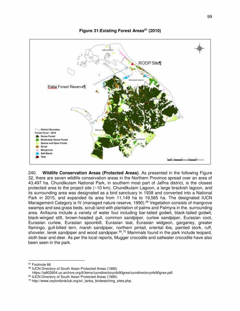
99
Figure 31:Existing Forest Areas67 (2010)
240. Wildlife Conservation Areas (Protected Areas). As presented in the following Figure 32, there are seven wildlife conservation areas in the Northern Province spread over an area of 43,497 ha. Chundikulam National Park, in southern most part of Jaffna district, is the closest protected area to the project site (~10 km). Chundikulam Lagoon, a large brackish lagoon, and its surrounding area was designated as a bird sanctuary in 1938 and converted into a National Park in 2015, and expanded its area from 11,149 ha to 19,565 ha. The designated IUCN Management Category is IV (managed nature reserve, 1990).68 Vegetation consists of mangrove swamps and sea grass beds, scrub land with plantation of palms and Palmyra in the. surrounding area. Avifauna include a variety of water foul including bar-tailed godwit, black-tailed godwit, black-winged stilt, brown-headed gull, common sandpiper, curlew sandpiper, Eurasian coot, Eurasian curlew, Eurasian spoonbill, Eurasian teal, Eurasian widgeon, garganey, greater flamingo, gull-billed tern, marsh sandpiper, northern pintail, oriental ibis, painted stork, ruff, shoveler, terek sandpiper and wood sandpiper.69,70 Mammals found in the park include leopard, sloth bear and deer. As per the local reports, Mugger crocodile and saltwater crocodile have also been seen in the park.
67 Footnote 66 68 IUCN Directory of South Asian Protected Areas (1990) https://ia802604.us.archive.org/6/items/iucndirectoryofs90gree/iucndirectoryofs90gree.pdf. 69 IUCN Directory of South Asian Protected Areas (1990). 70 http://www.ceylonbirdclub.org/sri_lanka_birdwatching_sites.php.
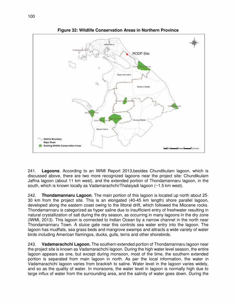
100
Figure 32: Wildlife Conservation Areas in Northern Province
241. Lagoons. According to an IWMI Report 2013,besides Chundikulam lagoon, which is discussed above, there are two more recognized lagoons near the project site: Chundikulam Jaffna lagoon (about 11 km west), and the extended portion of Thondamannaru lagoon, in the south, which is known locally as Vadamarachchi/Thalaiyadi lagoon (~1.5 km west). 242. Thondamannaru Lagoon. The main portion of this lagoon is located up north about 25-30 km from the project site. This is an elongated (40-45 km length) shore parallel lagoon, developed along the eastern coast owing to the littoral drift, which followed the Miocene rocks. Thondamannaru is categorized as hyper saline due to insufficient entry of freshwater resulting in natural crystallization of salt during the dry season, as occurring in many lagoons in the dry zone (IWMI, 2013). This lagoon is connected to Indian Ocean by a narrow channel in the north near Thondamannaru Town. A sluice gate near this controls sea water entry into the lagoon. The lagoon has mudflats, sea grass beds and mangrove swamps and attracts a wide variety of water birds including American flamingos, ducks, gulls, terns and other shorebirds. 243. Vadamarachchi Lagoon. The southern extended portion of Thondamannaru lagoon near the project site is known as Vadamarachchi lagoon. During the high water level season, the entire lagoon appears as one, but except during monsoon, most of the time, the southern extended portion is separated from main lagoon in north. As per the local information, the water in Vadamarachchi lagoon varies from brackish to saline. Water level in the lagoon varies widely, and so as the quality of water. In monsoons, the water level in lagoon is normally high due to large influx of water from the surrounding area, and the salinity of water goes down. During the
RODP Site

101
summers, the water level is very low, much of the lagoon area goes dry, and the water becomes highly saline. There are no studies or water quality data available on this lagoon. There are densely populated areas around the lagoon, and the vast land around it is occupied by agricultural lands (mostly paddy fields and coconut groves), scrublands, grasslands, and lands covered with Palmyra palms. The lagoon has mudflats and mangrove swamps and attracts a wide variety of water birds, although it is not a known or recognized bird area.
Figure 33: Major Lagoons in Jaffna Peninsula71
244. Jaffna lagoon is located at about 11 southwest of RODP site, and about 3 km from the water delivery point at Puthukkadu junction on Jaffna Kandy highway, i.e. end of conveyance pumping main. This is one of the large lagoons, annual salinity range is 28-37 ppt, with lower values during northeast monsoon while peak salinities in June. Jaffna and Chundikulam lagoons are inter connected with a narrow channel at elephant pass. This lagoon is known for its resident bird “Spot-billed Pelican (Pelecanus philippensis) and the habitat consists of wetland with tropical mangrove forests and salt marshes.72 245. Coastal & Marine Ecosystems. The coastal and marine environment in the Northern Province contains a large proportion of the coastal ecosystems; mangroves, coral reefs, sea grass beds and brackish water lagoons and salt marshes. In addition there are lagoons, inland water bodies and streams. Shallow coastal waters around Sri Lanka has an estimated 680 km2 of coral reefs; most of these shallow coral habitats are located in the Gulf of Mannar and along the east coast in the Trincomalee and Batticaloa Districts. In addition fringing coral reefs occur in the northern and southern areas of the island. Coral reefs of the Jaffna Peninsula are located mainly around islands in the Palk Bay and along the northern coastline in the Palk Strait.73 Mangroves
71 International Water Management Institute (2013). Lagoons of Sri Lanka: From the Origins to Present 72 http://datazone.birdlife.org/site/factsheet/jafna-lagoon-iba-sri-lanka/details 73 Dr. Ananda Mallawatantri, Prof. Buddhi Marambe, & Dr. Connor Skehan (2014). Integrated Strategic Environment
Assessment of the Northern Province of Sri Lanka. Central Environmental Authority & Disaster Management Centre of Sri Lanka. (This report is an output of a “A Multi-agency approach coordinated by the Central Environmental Authority and by the Disaster Management Centre, supported by the United Nations Development Programme (UNDP) and the United Nations Environment Programme (UNEP)”

102
found near the major islands. The west end of Jaffna Peninsula (Kayts Island), Uppuaru lagoon and Chalai lagoon comprise of important mangrove stands. Sea grass beds are distributed in the shallow coastal bays, such as Thondamaanar, Kurikadduwan, Pungudutivu, Mandaitivu and the Jaffna lagoon. There are no sea weeds in Jaffna district. 246. Coastal and marine conservation areas are depicted in the following Figure 34. The proposed project area is devoid of any sensitive coastal or marine features. A wading birds area is located in the nearby Vadamarachchi lagoon, along which the conveyance main is proposed.
Figure 34: Coastal & Marine Conservation Areas
Source: Integrated Strategic Environment Assessment of the Northern Province of Sri Lanka – see footnote 73
2. Major Habitat Types in the Study Area
247. Major type of natural habitats in this coastal belt are: scrublands, beaches and sand dunes. Scrublands are essentially in a state of accelerated flux that develops in places where land has been abandoned after human use or due to excessive degradation of forest. These are characterized by having a single stratum of shrubs (2 - 4 m in height) forming dense thickets. Very often, scattered trees are found within the scrub, which are remnants of original forest vegetation (Ashton et al., 1997). This type of scrub ecosystem can be observed throughout Jaffna Peninsula and many of the islands, and is not unique to the project site or surroundings. Beaches & sand dunes comprises land beyond the direct impact of waves and tides, where a carpet of densely growing creepers, comprising mainly of Ipomoea pes-caprae (Muhudu Bin Thamburu), are present. These creepers help consolidate the surface sand by restricting wind induced erosion and preventing removal of sand by sea water. Beyond the carpet of creepers a zone of low shrubs
RODP Site

103
occurs on the more stabilized sand and sand dunes. These again are spread along the Jaffna coast, and are not unique to the project site. 248. Vadamarachchi Lagoon. The area identified for the project located in the Central Asian Flyway, although not a recognized or key, but a potential entry and exist point of migratory birds that use the Central Asian Flyway. There are various lagoons in the area that provide excellent feeding and living habitats for a variety of water birds. Shallow brackish water lagoon (Vadamarachchi lagoon) located close to the project area with mangroves and mudflats provide a productive marine ecosystem that supports rich assemblage of fish and invertebrates which in turn the attract rich array of water birds, annual migrants, which use this area potentially for landfall and may be as a last staging point. This lagoon however mostly supports bird species that are commonly found. There are no species that are specifically found in this area that are absent or seldom found elsewhere in Sri Lanka. List of avifauna found in the lagoon area are presented in Table 27.
3. Terrestrial & Coastal Flora
249. There is no proper existing information on the ecology of this area, so qualitative surveys of the flora and fauna were conducted. Line transects were established across the project site and these were walked at different times by domestic specialists in the Sri Lankan flora and fauna, making observations as described below. 250. Plant species visible from each transect were identified by eye where possible, and by taking photographs and removing samples of leaves and fruiting bodies where present, for analysis in the laboratory. Identifications were conducted and field identifications were confirmed by reference to the “Handbook to the Flora of Ceylon”74 and other literature.75 Nomenclature of flowering plants was based on “A Checklist of the Flowering Plants of Sri Lanka”, and the conservation status of each species was determined by consulting The National Red List 2012 of Sri Lanka76 and The IUCN Red List of Threatened Species 2016.77 251. Table 18 provides a list of all plant species recorded at the project site, their habit (growth form) and conservation status. This data and the site observations indicate that there are two vegetation associations in this area. Above the beach beyond the direct impact of tides and waves, is an area of low-form sand dunes, with a carpet of densely growing creepers, mainly of Ipomoea pes-caprae (Goat’s foot), which covers and consolidates the sand, providing protection from erosion by wind, rainfall or extreme high tides. A little farther inland (scrubland), some low-growing shrubs are also present, including Calotropis gigantea (crown flower) and Premna obtusifolia, along with the halophytic78 grass Spinifex littoreus, and some halophytic herbs, Cyperus stoloniferus and Sesuvium portulacastrum (sea purslane), which provide a denser ground cover and a more stable sand surface.
74 Dassanayake M D (and others), Editors (1980-2005): A Revised Handbook to the Flora of Ceylon, Volumes 1-15.
(Revisions of the original series by Trimen and Hooker, first published in 1893-1900) 75 Ashton M S, Gunatilleke S, de Zoysa N, Dassanayake M D, Gunatilleke N and Wijesundera S (1997): A field guide
to the common Trees and Shrubs of Sri Lanka. WHT Publications (http://www.wht.lk/ebooks/single-gallery/15475786)
76 MOE (2012): The National Red List 2012 of Sri Lanka; Conservation Status of the Fauna and Flora. Ministry of Environment, Colombo, 476 pp (http://www.cea.lk/web/images/pdf/redlist2012.pdf)
77 IUCN (2016): The IUCN Red List of Threatened Species. International Union for Conservation of Nature, Gland, Switzerland (http://www.iucnredlist.org/)
78 Halophytes are plants that are salt-tolerant and adapted to living in saline conditions, such as found on or near seashores
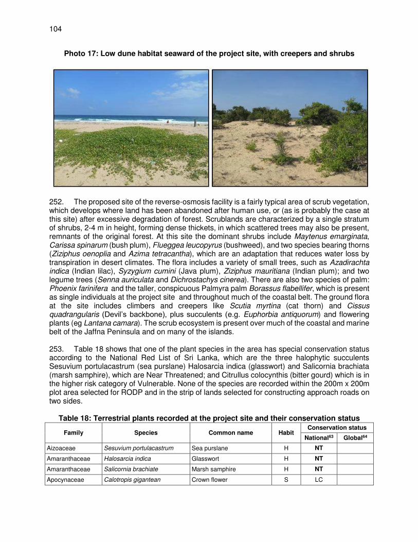
104
Photo 17: Low dune habitat seaward of the project site, with creepers and shrubs
252. The proposed site of the reverse-osmosis facility is a fairly typical area of scrub vegetation, which develops where land has been abandoned after human use, or (as is probably the case at this site) after excessive degradation of forest. Scrublands are characterized by a single stratum of shrubs, 2-4 m in height, forming dense thickets, in which scattered trees may also be present, remnants of the original forest. At this site the dominant shrubs include Maytenus emarginata, Carissa spinarum (bush plum), Flueggea leucopyrus (bushweed), and two species bearing thorns (Ziziphus oenoplia and Azima tetracantha), which are an adaptation that reduces water loss by transpiration in desert climates. The flora includes a variety of small trees, such as Azadirachta indica (Indian lilac), Syzygium cumini (Java plum), Ziziphus mauritiana (Indian plum); and two legume trees (Senna auriculata and Dichrostachys cinerea). There are also two species of palm: Phoenix farinifera and the taller, conspicuous Palmyra palm Borassus flabellifer, which is present as single individuals at the project site and throughout much of the coastal belt. The ground flora at the site includes climbers and creepers like Scutia myrtina (cat thorn) and Cissus quadrangularis (Devil’s backbone), plus succulents (e.g. Euphorbia antiquorum) and flowering plants (eg Lantana camara). The scrub ecosystem is present over much of the coastal and marine belt of the Jaffna Peninsula and on many of the islands. 253. Table 18 shows that one of the plant species in the area has special conservation status according to the National Red List of Sri Lanka, which are the three halophytic succulents Sesuvium portulacastrum (sea purslane) Halosarcia indica (glasswort) and Salicornia brachiata (marsh samphire), which are Near Threatened; and Citrullus colocynthis (bitter gourd) which is in the higher risk category of Vulnerable. None of the species are recorded within the 200m x 200m plot area selected for RODP and in the strip of lands selected for constructing approach roads on two sides.
Table 18: Terrestrial plants recorded at the project site and their conservation status
Family Species Common name Habit Conservation status
National63 Global64
Aizoaceae Sesuvium portulacastrum Sea purslane H NT
Amaranthaceae Halosarcia indica Glasswort H NT
Amaranthaceae Salicornia brachiate Marsh samphire H NT
Apocynaceae Calotropis gigantean Crown flower S LC

105
Family Species Common name Habit Conservation status
National63 Global64
Apocynaceae Carissa spinarum Bush plum S LC
Apocynaceae Catharanthus roseus Madagascar periwinkle S
Arecaceae Borassus flabellifer Palmyra palm T
Arecaceae Phoenix farinifera Palm T
Asteraceae Blumea oblique H LC
Asteraceae Tridax procumbens Tridax daisy H
Celastraceace Maytenus emarginata S LC
Convolvulaceae Cressa cretica Morning glory H LC LC
Convolvulaceae Ipomoea pes-caprae Goat’s foot H LC
Cucurbitaceae Citrullus colocynthis Bitter gourd H VU
Cyperaceae Cyperus stoloniferus H LC LC
Cyperaceae Fimbristylis spp Sedge H
Euphorbiaceae Euphorbia antiquorum Antique spurge T LC
Fabaceae Senna auriculata Avaram senna T LC
Fabaceae Dichrostachys cinerea Sicklebush S LC LC
Lamiaceae Gmelina asiatica T LC
Lamiaceae Premna obtusifolia C LC
Meliaceae Azadirachta indica Indian lilac T
Moraceae Ficus benghalensis Indian banyan T LC
Myrtaceae Syzygium cumini Java plum T LC
Pedaliaceae Pedalium murex H LC
Phyllanthaceae Flueggea leucopyrus Bushweed S LC
Poaceae Cynodon dactylon Couch grass G LC
Poaceae Spinifex littoreus Ravan’s moustache G LC
Rhamnaceae Scutia myrtina Cat thorn C LC
Rhamnaceae Ziziphus mauritiana Indian plum S LC
Rhamnaceae Ziziphus oenoplia Wild jujube S LC
Rubiaceae Catunaregam spinosa Mountain pomegranate S LC
Salvadoraceae Azima tetracantha S LC
Verbanaceae Lantana camara Wild sage S
Vitaceae Cissus quadrangularis Devil’s backbone C LC
Conservation categories (in increasing order of importance): Blank = Not Evaluated; DD = Data Deficient; LC = Least Concern; NT = Near Threatened; VU = Vulnerable; E = Endangered; CE = Critically Endangered; EW = Extinct in the Wild; EX = Extinct, Habit: G = Grass; H = Herbaceous; S = Shrub; T = Tree; C = Climber or Creeper.

106
4. Terrestrial Fauna
254. The fauna species present in the project area are identified based on the following methods of record: Table 19 is the resulting list of species present at the terrestrial part of the project site, which identifies the method through which each record was obtained.
(i) direct observation of individuals in the field, coupled with expert recognition of indirect signs (calls, pellets and tracks) for individuals that were not actually sighted. These observations were made by following the same transects as the floral survey described above, and by diverging away from transects where necessary.
(ii) Some additions to the species list were made in discussion with local people and officials, if informants were judged to be sufficiently skilled in animal recognition for the record to be accepted with confidence.
(iii) Some other additions were made based on sightings reported in published literature and reliable unpublished data.
255. Scrub vegetation often develops in areas that are neglected by man, where the undisturbed nature of the habitat makes it attractive for colonisation by a variety of animals. Diversity is limited however by the restricted tree cover, which excludes high-nesting/ roosting birds for example; and in this case, animal inhabitation is further limited by the relatively harsh conditions provided by the saline, sandy soil, and by the absence of standing water or perennial rivers. Nevertheless the species list shows a good diversity, dominated by birds, but also with a varied composition of both mammals and reptiles.
Table 19: Terrestrial animals recorded at the project site and their conservation status
Family Species Common name Conservation status
Method of Record
National63 Global64
Class Aves
Sturnidae Acridotheres tristis Common mynah LC LC OB Ardeidae Ardea cinerea cinerea Grey heron PR Ardeidae Bubulcus ibis Cattle egret LC LC OB
Cercotrichas Copsychus saularis Oriental magpie-robin
LC LC OB
Corvidae Corvus splendens House crow LC LC OB Dicruridae Dicrurus macrocercus Black drongo LC LC OB Recurvirostridae Himantopus himantopus Black-winged stilt LC LC OB
Meropidae Merops orientalis orientalis
Green bee-eater OB
Ardeidae Mesophoyx intermedia Intermediate egret LC OB Ciconiidae Mycteria leucocephala Painted stork LC NT PR Nectariniidae Nectarinia asiatica Purple sunbird LC LC Call
Nectariniidae Nectarinia zeylonica Purple-rumped sunbird
LC LC OB
Cisticolidae Orthotomus sutorius Common tailorbird LC LC OB Phasianidae Pavo cristatus Indian peafowl LC LC PR Pelecanidae Pelecanus philippensis Spot-billed pelican LC NT OB Phalacrocoracidae Phalacrocorax pygmeus Pygmy cormorant OB Pittidae Pitta sordida Hooded pitta LC OB Saxicoloides Saxicoloides fulicata Indian robin LC OB Sternidae Sterna albifrons Little tern LC LC
Columbidae Streptopelia chinensis ceylonensis
Spotted dove OB
Monarchidae Terpsiphone paradise Asian paradise flycatcher
LC LC OB

107
Family Species Common name Conservation status
Method of Record
National63 Global64 Tringa glareola Wood sandpiper LC
Turdoides Turdoides affinis Yellow-billed babbler LC LC OB
Charadriidae Vanellus cinereus Grey-headed lapwing
LC OB
Class Reptilia
Colubridae Ahaetulla nasuta Green vine snake LC PR Natricidae Amphiesma stolatum Buff striped keelback LC PR Elapidae Bungarus caeruleus Common krait LC PR
Agamidae Calotes versicolor Oriental garden lizard
LC OB
Crocodylidae Crocodylus porosus Salt-water crocodile EN LC Local info Hydrophiinae Enhydrina schistose Beaked sea snake LC LC PR
Chelonidae Eretmochelys imbricate Hawksbill sea turtle EN CE Unconfirmed local info
Elapidae Naja naja Indian cobra LC PR
Elapidae Pelamis platura Yellow-bellied sea snake
LC LC PR
Pythonidae Python molurus molurus Indian python PR Class Mammalia
Canidae Canis aureus Golden jackal LC LC PR
Sciuridae Funambulus palmarum Common palm squirrel
LC LC Observed
Herpestidae Herpestes edwardsi Indian grey mongoose
LC LC Local info
Herpestidae Herpestes smithii Ruddy mongoose LC LC Local info
Hystricidae Hystrix indica Indian crested porcupine
LC LC Presence of
spines Leporidae Lepus nigricollis Black-naped hare LC LC Pellatts Suidae Sus scrofa Wild boar LC LC Tracks Class Insecta
Pieridae Delias eucharis Jezebel butterfly LC PR Nymphalidae Hypolimnas bolina Great eggfly butterfly LC PR
Papilionidae Pachliopta hector Crimson rose butterfly
LC PR
Papilionidae Papilio polytes Mormon butterfly LC PR Class Arachnida
Scorpionidae Heterometrus sp Giant forest scorpion PR Buthidae Hottentotta sp Scorpion PR
Conservation categories (in increasing order of importance): Blank = Not Evaluated; DD = Data Deficient; LC = Least Concern; NT = Near Threatened; VU = Vulnerable; E = Endangered; CE = Critically Endangered; EW = Extinct in the Wild; EX = Extinct; Method of Record: OB=Observed; PR = Previous Records; Local info=provided by villagers 256. Most of the birds live and breed at the site, although their highly mobile nature means that many will inhabit other areas at different times and in different seasons. The avifauna includes a range of habits and ecological niches,79 from the seed-eating spotted dove (Streptopelia chinensis ceylonensis), insectivorous hooded pitta (Pitta sordida), omnivorous Indian robin (Saxicoloides fulicata) and common mynah (Acridotheres tristis), to the fish- and amphibian-eating cormorants (Phalacrocorax pygmeus and P fuscicollis) and intermediate egret (Mesophoyx intermedia). One notable element is the number and variety of waders at the site: sandpiper (Tringa glareola); stilt (Himantopus himantopus); two egrets (Bubulcus ibis and Mesophoyx intermedia); stork (Mycteria leucocephala); and heron (Ardea cinerea cinerea). These will feed on the beach and in the shallows, and probably roost and nest at the inland part of the site. The same is true for the other
79 An ecological niche is the role and position a species has in its environment; how it meets its needs for food and
shelter, how it survives, and how it reproduces
108
water birds recorded, such as the cormorants and pelican (Pelecanus philippensis), which will also feed in deeper waters. 257. The influence of the adjacent marine habitat is also evident in some of the reptiles recorded at the site, in particular the salt-water crocodile (Crocodylus porosus) and the hawksbill sea turtle (Eretmochelys imbricata). However, presence of these species at the site is not established firmly by any of the reliable methods or sources (direct or indirect observations, published data or credible local information), but included in the list based on vague information from few local people. Inclusion in the list here is necessitated because these species enjoy protected status, and inclusion here will ensure proper measures to avoid any impact on them, even if the possibility of them visiting the site is very remote. If present at the site, these will be seasonal visitors, as females of both species lay eggs in soft sand above the high water mark, after which female turtles return to the sea. Female salt-water crocodiles however remain on land guarding the nest for the three month gestation period, sometimes assisted by the male. Crocodiles may also bask on land, although they spend most of the time in the water. The other reptiles recorded at the project area comprise seven snakes and the common garden lizard (Calotes versicolor). Two of the snakes are sea snakes (Enhydrina schistosa and Pelamis platura) and will therefore only be seen on the beach or in the immediate inland area. The other snakes are mostly species that live near freshwater, so they could be present because of the high water table, and the pools of surface water that sometimes form during monsoon rainfall (the survey was conducted in December 2015). 258. The rest of the fauna is quite typical of scrubland areas, and includes a variety of small mammals, some of which live in burrows in the sand (Indian grey mongoose Herpestes edwardsi, ruddy mongoose Herpestes smithii and black-naped hare Lepus nigricollis). These mainly forage at night, while the larger mammals present (wild boar Sus scrofa and golden jackal Canis aureus) feed mainly during the daytime. The invertebrate fauna is underrepresented in the survey as there would almost certainly be more species of insect than the four butterflies recorded, along with other groups, such as spiders, worms and molluscs. This is probably a result of the survey methodology, which mainly relied on visual observations of animals and signs of their presence, and did not include netting or other methods aimed at invertebrates. 259. Table 19 shows that four of the animal species have an “at-risk” conservation status. These are two of the large water birds: the painted stork (Mycteria leucocephala) and the spot-billed pelican (Pelecanus philippensis), which are both “Near Threatened” according to IUCN Redlist, while are of Least Concern as per the national list; and the two marine reptiles - the hawksbill sea turtle (Eretmochelys imbricata) and the salt-water crocodile (Crocodylus porosus). Both of these reptiles are “endangered” as per the national list. According to IUCN, and the hawkbill sea turtle is Critically Endangered, which means that it is facing an extremely high risk of extinction in the wild, while the salt-water crocodile is at “lower risk or least concern”. As presented in the Table 19, sitings of hawksbill turtle at the project is unconfirmed. Based on the published information and knowledge of local area and species, the following description of each at risk species is prepared by LHI Ecological Experts.80 260. Painted stork. The painted stork (Mycterialeucocephala) is a large wading bird in the stork family. Although one of the most abundant of the Asian storks, this species is classified as Near Threatened by the IUCN Red list because it is thought to be undergoing a moderately rapid population decline owing primarily to hunting, wetland drainage and pollution (Urfi, 2011) but Painted stork is considered as a “Least concern species” in Sri Lanka. It is probably more 80 LHI, 2017. A Note on Ät Risk Species at project site (Ref Appendix P).

109
widespread over a greater variety of habitats. They are locally abundant, particularly in the dry zone and use wetlands as their feeding and breeding grounds (Henry, 1955; Urfi, 2011).They are mainly seen on freshwater wetlands (marshes, lakes and reservoirs, flooded fields, rice paddies, freshwater swamp forest, river bank) although sometimes forage on the coast (intertidal mudflats, lagoon, estuaries). Painted stork is not migratory and only makes short distance movements in some parts of their range in response to changes in weather or food availability or for breeding. 261. They are found in the northern half of the island and down the eastern low country to about the Tangalle district, wherever tanks, large swamps and secluded lagoons given them safe feeding grounds (Henry, 1955;Chandana et al., 2008). However, their being sites are limited and most important large nesting colonies have been recorded from Kumana-villu of the Yala East National Palk (Kaluthota et al., 2005) and also from other protected areas of Sri Lanka such as Bundala National Park, Udawalawe National Palk Benthem et al., 1993; De Silva and Jakosson, 1996; Chandana, et al.2008).They nest in colonies and the nest is a thick platform of twigs placed on a low tree. The breeding season varies from October to May, follows the onset of the monsoon. 262. Occurrence in and around project area. The painted stork is reported from Chundikulam, Kayts causeway and Pungudutheevu in Jaffna but occasionally observed in the wetland areas of Thalaiyadi. The area is not a well-known roosting or feeding site. It is considered as a “Least concern species” in Sri Lanka but Global conservation status is “Near threatened”. 263. Spot-billed pelican. Spot billed pelican (Pelecanusphilippensis) is one of the important bird species categorized as threatened under the IUCN Red Data list in 2003. However, their population has recovered due to many conservation measures resulting in its conservation status been down listed to a near threatened species in 2007. The only known present day breeding populations occur in Sri Lanka, India and Cambodia (Threatened birds of Asia, the Birdlife International Red Data Book). According to the Asian Red data book, this species in Sri Lanka is under threat due to the loss of habitat, disturbances to breeding sites, cutting of mangroves and excessive fishing and hunting. Spot billed pelican is the only resident pelican species found in Sri Lanka and shows a wider distribution, even adopted to breed in highly urbanized areas but depends solely on limited breeding sites (Jayawardena, 2011). They commonly resident in tanks, lagoons and marshlands of the low country dry zone wetlands in Sri Lanka It lives as flocks from two or three birds to hundreds. The breeding season is from October to May and the nest is a large platform of sticks and reeds, placed on trees growing in flooded areas or swamps. In Colombo area spot-billed pelican nest close to human habitations. Although it is common in Sri Lanka especially in the Northern region too, Spot-billed Pelican is considered as a globally endangered species. The local population is thought to be stable (Collar Andrew, 1988); occurs in Yala East, Ruhuna (Yala) and Wilpattu National Parks, the Bundala Sanctuary, and Puttalam Lagoon, (Scott, 1989). 264. Wetlands and marshlands in Thalaiyadi provide favourable environment for a variety of both resident and migratory birds including painted stork and Spot-billed pelican. However, the area is not a well-known foraging, roosting or breeding site of painted stork. They breed in trees along with other water birds. The platform nests are typically placed in a tree on adjacent to foraging site or in an otherwise undisturbed area. In some areas where they have been left undisturbed they nest very close to human habitations. The best nesting sites are at the tops of the trees and birds jostle for these locations. 265. Salt-water crocodile. Two species of crocodile occur in Sri Lanka, namely the marsh crocodile (Crocodyluspalustris) and the estuarine/saltwater crocodile (Crocodylusporosus). Both species have declined in range and number since the turn of the century, mainly through over-

110
hunting for hide and meat in the past, and conversion of their habitat to other land-use at present. Eastern, south-eastern lowland areas including mainly Panama, Bundala and Yala National Parks, Western and North-western areas including Northern areas of the country provide habitats for the saltwater crocodile at present. It is a man-eating crocodile and is not endemic. It’s mainly a solitary species and have their own territories, especially males. They like lurking around deltas and mangrove swamps. Unlike the Mugger Crocodiles who seem to like to bask in the sun in groups. A saltwater crocodile can grow up to six to seven meters in length and some can be dangerous to man. It swims long distances in saltwater to hunt for new feeding locations. 266. Both are listed on Appendix I of CITES, and so their international trade is banned. In Sri Lanka, the two species would meet the IUCN criteria for being ‘endangered’ and ‘critically endangered’ respectively. However, no formal long-term study has been made on either species in Sri Lanka. The habitats of the saltwater crocodile are generally confined to the coastal region but sometimes they travel far up rivers. It occurs in the estuaries of the larger rivers, coastal mangroves, marshes, swamps and some inland water bodies. The saltwater crocodile had a wider distribution in Sri Lanka than the marsh species. They are quite difficult to see, but frequently reported from Nilwala-ganga of the Matara district, Madu-ganga of the Galle district, Bolgoda and Kaluriver of the Kalutara district, and Muthurajawela of the Gampaha district are a familiar sight. During the heavy rainfalls of the south-western monsoons, these crocs get caught in strong currents and are washed to the sea shores. They stay here for a couple of days before moving upstream once again. 267. Both crocodiles did occur in the distant past in the Jaffna peninsula. But with increased urbanization, crocodiles began to decline both in range and number in the peninsula and for some time, they were generally believed to have become locally extinct there for several decades. An island-wide survey of the crocodiles carried out by Rom and Zai Whitaker in 1977 could not find any in the Thondamannaru lagoon. However, recent survey carried out in the Jaffna peninsula, in and around the Thondamannaru lagoon confirmed the presence of both crocodiles (about 30-35 km from project area). Saltwater crocodiles were recorded from several places such as Varani, Ampan, Maruthankerny, Maanvilunthakooru, Mulliyan and from the extensive mangroves along the Thondamannaru lagoon in Jaffna Peninsula. Although salt-water crocodile is rarely sighted it can be found in Thalaiyadi lagoon (southeast part of Vadamarachchi lagoon). Although salt-water crocodile is rarely sighted it can be found in Thalaiyadi lagoon (southeast part of Vadamarachchi lagoon). 268. Saltwater crocodiles breed only once a year. It is likely that the two monsoons that occur annually in the island have a bearing on the breeding regimes. They breed during the wet season. Despite the fact that the saltwater crocodile is normally found in saltwater areas, breeding grounds are established in fresh water. 269. Hawksbill sea turtle. Sri Lanka’s sandy beach is a nesting ground for five species of marine turtles which include the Green Turtle, the Leatherback, the Hawksbill, the Loggerhead and the Olive Ridley. All 5 species have been recorded to nest along specific areas of Sri Lanka’s coast. Hawksbill (Eretmochelysimbricata) nesting is sparse and this species is considered uncommon in Sri Lanka. It is mainly found around Batticaloa, Pasekudah to Kalkuda and Kalmunai (Eastern Coast), Yala National Park and Bundala Sanctuary (South-eastern coast) Hambantota, Kosgoda,Induruwa and Unawatuna(Southern coast) and nesting period of E. imbricata recorded from December to January and April to June[(Dattatri&Samarajeewa(1982), Scott (1989)]. Fishing practices of Sri Lanka threaten E. imbricata populations, and national conservation status for the species is “Endangered” and The World Conservation Union classifies the hawksbill globally as critically endangered. There is no evidence of nesting site in or near the

111
project area either from literature or from the local community/ researchers. Hawksbill turtle are most commonly found in hard bottomed and reef habits containing sponges and coral reefs. They usually rest in caves and ledges in and around the reefs throughout the day. When they young they unable to dive into deep-water and live in mass of floating sea-plants such as Sargassum. The project site and its surround does not provide such an appealing environment for Hawksbill turtle. 270. Very little is known about presence of sea turtle in the coastal waters of Maruthankerny/Thalaiyadi. There is no record of nesting or foraging of any sea turtle species within the project area or the adjacent sea areas. The occurrence of Hawksbill (Eretmochelysimbricata) is generally reported in association with reef habitats. Since the coastal sea of Maruthankerny is lacking of reef habits it is unlikely to be observed Hawksbill sea turtles in the area. 271. Nesting season of sea turtle species is unpredictable and it is unknown what event triggers the animals to nest. Certain phases of the moon and tide and weather conditions (monsoon) have been suggested as triggers. The main breeding season of sea turtles reported in main nesting sites; from October to February on the far south, in the south from September to mid-April, in the west coast January/February to June and on the East coast. (Turtles and Tortoises in Sri Lanka). During the period from July to August, a smaller number of turtles use the beaches of Arugam Bay (USAID, 2006). Nesting are found year round in major nesting sites such as Rekawa, Benthota, Panama. Normally Turtles are on the shore during the full moon, when they come to lay their eggs. There are several nesting grounds identified in, but none are located near the project area.
5. Marine Ecology
272. In contrast to the relative paucity of habitats and limited diversity of species in the terrestrial environment, the coastal waters of Jaffna offer a wide variety of habitat types, and a richness of inhabiting species that is amongst the highest in Sri Lanka. According to the national Coastal Zone Management Plan,81 Jaffna has the highest proportion of salt marsh, sand dune, lagoon and estuarine habitat in the country, and the second-highest area of mangrove (Table 20).
Table 20: Coastal habitats of Sri Lanka, and the area (ha) of each in Jaffna District82
Mangrove Salt
Marsh Dune
Beach, Spit
Lagoon Estuary Other
water body Freshwater
marsh Shrimp farms
Total 6,083 23,797 15,546 5,621 36,178 90,811 2,350 6,555 5,455
Jaffna 1,088 6,524 6,710 565 9,983 29,613 343 - -
Jaffna % 17.9 27.4 43.2 10.1 27.6 32.6 14.6 0 0
273. Figure 35 shows the distribution of coastal habitats on the Jaffna Peninsula and the adjacent mainland, which can be summarised as follows:
(i) Jaffna lagoon is a large area of estuarine habitat, classified as such because it is open to the sea in the west and receives inputs of brackish water from inland lagoons in the northwest and southeast;
81 CCD (2004): Coastal Zone Management Plan (CZMP) Update 2004. Coast Conservation Dept, Colombo,
(http://www.coastal.gov.lk/index.php?option=com_content&view=article&id=118&Itemid=109&lang=en) 82 Joseph L (2004): National Report of Sri Lanka on the Formulation of a Transboundary Diagnostic Analysis and
Strategic Action Plan for the Bay of Bengal Large Marine Ecosystem Programme. Bay of Bengal Large Marine Ecosystem Programme (BOBLMEP), 115 pp (http://www.boblme.org/documentRepository/Nat_Sri_Lanka.pdf)

112
(ii) Jaffna Lagoon has sandy beaches along the eastern side and a large area of tidal flats in the west, which are uncovered during low tide;
(iii) Sea grass beds cover large areas along the north coast and in the channel between Jaffna Peninsula and Karainagar and Kayts islands;
(iv) Beach habitats occur along most of the north-eastern coastline, from Point Pedro southwards;
(v) Sand dune is the most widely dispersed habitat, found in a large area south of Point Pedro, along the western coast, on most of the islands, and in small patches elsewhere, including the edges of lagoons and some inland areas;
(vi) Coral reef habitats are found around the islands in the northwest, park strait, part bay and at Devil’s Point in Palk Bay south of Jaffna as well as along the northern coast up to Point Pedro.
(vii) Mangrove swamps are found only on the inland side of Mandaitivu Island and the adjacent south-western tip of Kayts island.
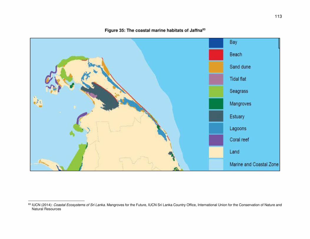
113
Figure 35: The coastal marine habitats of Jaffna83
83 IUCN (2014): Coastal Ecosystems of Sri Lanka. Mangroves for the Future, IUCN Sri Lanka Country Office, International Union for the Conservation of Nature and
Natural Resources
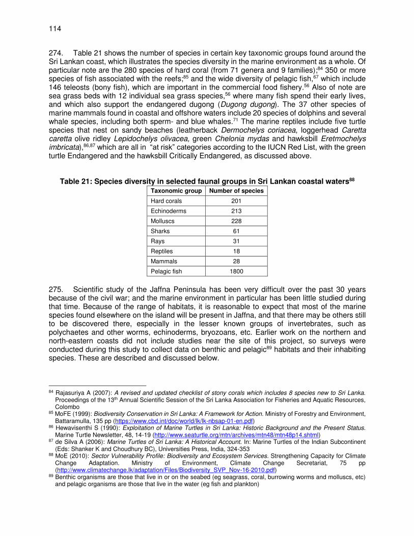
114
274. Table 21 shows the number of species in certain key taxonomic groups found around the Sri Lankan coast, which illustrates the species diversity in the marine environment as a whole. Of particular note are the 280 species of hard coral (from 71 genera and 9 families);84 350 or more species of fish associated with the reefs;85 and the wide diversity of pelagic fish,67 which include 146 teleosts (bony fish), which are important in the commercial food fishery.56 Also of note are sea grass beds with 12 individual sea grass species,56 where many fish spend their early lives, and which also support the endangered dugong (Dugong dugong). The 37 other species of marine mammals found in coastal and offshore waters include 20 species of dolphins and several whale species, including both sperm- and blue whales.71 The marine reptiles include five turtle species that nest on sandy beaches (leatherback Dermochelys coriacea, loggerhead Caretta caretta olive ridley Lepidochelys olivacea, green Chelonia mydas and hawksbill Eretmochelys imbricata),86,87 which are all in “at risk” categories according to the IUCN Red List, with the green turtle Endangered and the hawksbill Critically Endangered, as discussed above.
Table 21: Species diversity in selected faunal groups in Sri Lankan coastal waters88
Taxonomic group Number of species
Hard corals 201
Echinoderms 213
Molluscs 228
Sharks 61
Rays 31
Reptiles 18
Mammals 28
Pelagic fish 1800
275. Scientific study of the Jaffna Peninsula has been very difficult over the past 30 years because of the civil war; and the marine environment in particular has been little studied during that time. Because of the range of habitats, it is reasonable to expect that most of the marine species found elsewhere on the island will be present in Jaffna, and that there may be others still to be discovered there, especially in the lesser known groups of invertebrates, such as polychaetes and other worms, echinoderms, bryozoans, etc. Earlier work on the northern and north-eastern coasts did not include studies near the site of this project, so surveys were conducted during this study to collect data on benthic and pelagic89 habitats and their inhabiting species. These are described and discussed below.
84 Rajasuriya A (2007): A revised and updated checklist of stony corals which includes 8 species new to Sri Lanka.
Proceedings of the 13th Annual Scientific Session of the Sri Lanka Association for Fisheries and Aquatic Resources, Colombo
85 MoFE (1999): Biodiversity Conservation in Sri Lanka: A Framework for Action. Ministry of Forestry and Environment, Battaramulla, 135 pp (https://www.cbd.int/doc/world/lk/lk-nbsap-01-en.pdf)
86 Hewavisenthi S (1990): Exploitation of Marine Turtles in Sri Lanka: Historic Background and the Present Status. Marine Turtle Newsletter, 48, 14-19 (http://www.seaturtle.org/mtn/archives/mtn48/mtn48p14.shtml)
87 de Silva A (2006): Marine Turtles of Sri Lanka: A Historical Account. In: Marine Turtles of the Indian Subcontinent (Eds: Shanker K and Choudhury BC), Universities Press, India, 324-353
88 MoE (2010): Sector Vulnerability Profile: Biodiversity and Ecosystem Services. Strengthening Capacity for Climate Change Adaptation. Ministry of Environment, Climate Change Secretariat, 75 pp (http://www.climatechange.lk/adaptation/Files/Biodiversity_SVP_Nov-16-2010.pdf)
89 Benthic organisms are those that live in or on the seabed (eg seagrass, coral, burrowing worms and molluscs, etc) and pelagic organisms are those that live in the water (eg fish and plankton)

115
6. Benthic flora and fauna
276. A SCUBA diving survey was conducted adjacent to the proposed RODP site in March 2016, in an area of 500 x 1500 m (long axis perpendicular to the coast). The belt transect method90 was used, whereby two divers operated side-by-side, each covering a width of 2.5 m on opposite sides of a swim line, observing, recording and photo-documenting all visible marine life. Eleven swim lines were established randomly throughout the survey area, and GPS coordinates were taken at the start and end of each. Swim lines varied from 200 to 450 m in length, and several repetitive dives were carried out in each case, to cover the relatively long distances involved. The total distance covered was 3,340 m and with a 5 m visual path, the total survey area was 16,700 m2. 277. The survey was conducted by national experts in the ecology of Sri Lankan coastal waters, and organisms sighted were identified visually on the basis of extensive previous experience. The abundance of each species or taxonomic group was estimated based on the ACFOR qualitative abundance scale,91 and this was supplemented by counts of actual numbers of individuals where practicable. This data and additional information on habitat, sediment composition and other environmental features was recorded on underwater slates; and the conservation status of all taxa present was determined on return to the laboratory by reference to the IUCN and national red data lists. 278. Table 22 lists the species recorded during the survey, their estimated abundance and conservation status, and Photos 17-19 show several of the individuals in situ. The survey revealed that the seabed in this area is entirely composed of sand, and there are no areas of rock, coral, sea grass or other types of habitat. Sand is among the least productive of marine habitats and normally occurs in areas of strong currents and/or wave action, which do not allow finer suspended material to settle out, so there is little organic matter in the sediment to support detrital feeders at the base of the food chain. That is probably the case at this site, as the sand at the outer part of the study area was quite coarse, containing large amounts of shell debris, but it also contained some fine silt, and the colour was light brown or grey as a result. Closer to the shore there was little evidence of silt amongst the sand, because of the increased wave action.
Table 22: Marine species recorded during a diving survey at the project site
Phylum Class Species Common Name Observed
abundance at this site
Conservation status
Nat’l Global
Porifera Unidentified Sponges Rare Cnidaria Anthozoa Stichodactyla sp Carpet anemone 1 - Rare
Cerianthus sp Tube anemone 1 - Rare FFPO Cycloseris cyclolites Mushroom coral 2* - Rare FFPO LC Dendronephthya sp Soft coral 1 - Rare FFPO Gorgonians Sea whips/fans 4 - Rare FFPO
Mollusca Bivalvia Pinna sp Pen shells Occasional Family Veneridae Venus clams Occasional Family Pectinidae Scallops Occasional Gastropoda Turbinella pyrum Sacred chank Occasional
90 English S A, Wilkinson C and Baker V J (1997): Survey Manual for Tropical Marine Resources, 2nd Edition. Australian
Institute of Marine Science, Townsville, Australia, 390 pp (http://www.aims.gov.au/documents/30301/23122/Survey+Manual-sm01.pdf/3b521f46-efad-4253-a5ef-
67bd049d1835) 91 The ACFOR scale (Abundant, Common, Frequent, Occasional, Rare) is a qualitative method of estimating the
abundance of a species or habitat, and is used in situations where it is impracticable to count numbers of individuals, for example where examining dense vegetation, or in diving surveys.
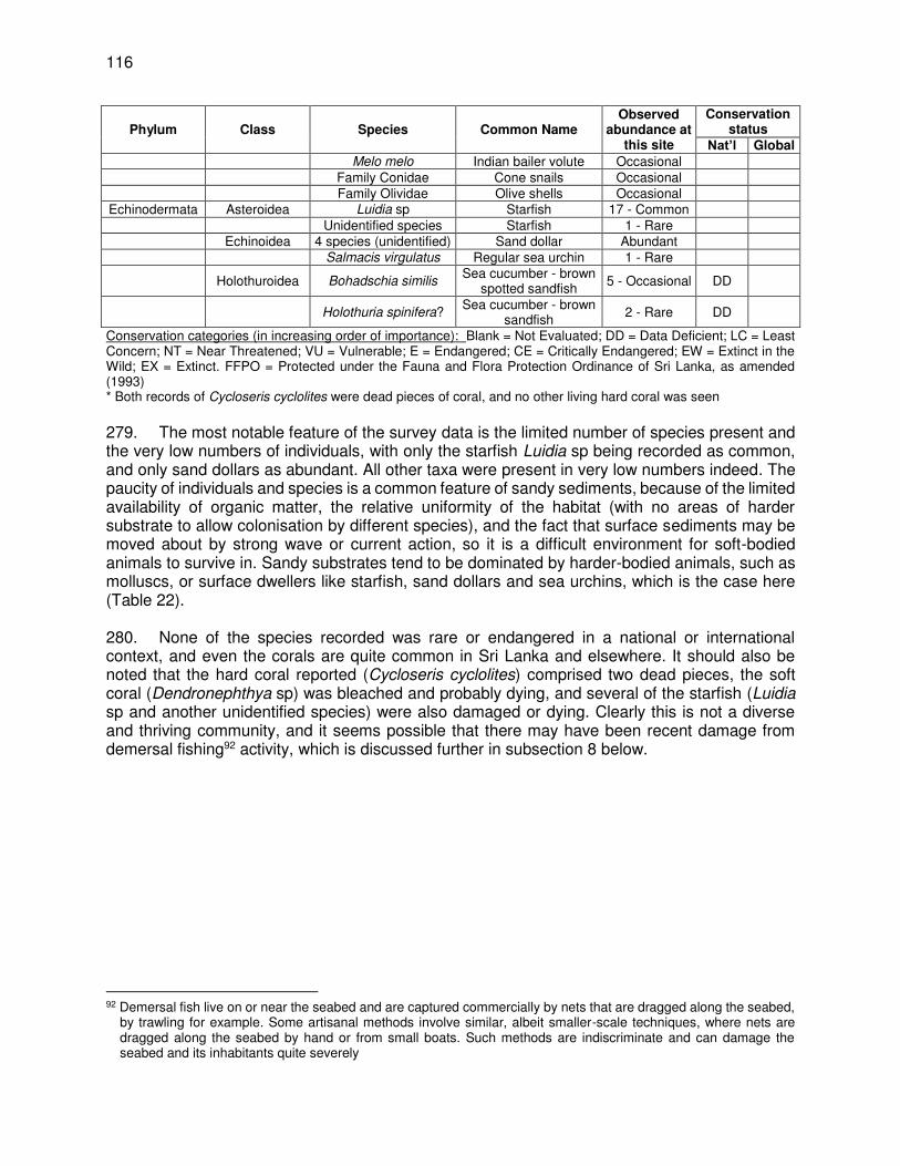
116
Phylum Class Species Common Name Observed
abundance at this site
Conservation status
Nat’l Global
Melo melo Indian bailer volute Occasional Family Conidae Cone snails Occasional Family Olividae Olive shells Occasional
Echinodermata Asteroidea Luidia sp Starfish 17 - Common Unidentified species Starfish 1 - Rare Echinoidea 4 species (unidentified) Sand dollar Abundant Salmacis virgulatus Regular sea urchin 1 - Rare
Holothuroidea Bohadschia similis Sea cucumber - brown
spotted sandfish 5 - Occasional DD
Holothuria spinifera? Sea cucumber - brown sandfish
2 - Rare DD
Conservation categories (in increasing order of importance): Blank = Not Evaluated; DD = Data Deficient; LC = Least Concern; NT = Near Threatened; VU = Vulnerable; E = Endangered; CE = Critically Endangered; EW = Extinct in the Wild; EX = Extinct. FFPO = Protected under the Fauna and Flora Protection Ordinance of Sri Lanka, as amended (1993) * Both records of Cycloseris cyclolites were dead pieces of coral, and no other living hard coral was seen 279. The most notable feature of the survey data is the limited number of species present and the very low numbers of individuals, with only the starfish Luidia sp being recorded as common, and only sand dollars as abundant. All other taxa were present in very low numbers indeed. The paucity of individuals and species is a common feature of sandy sediments, because of the limited availability of organic matter, the relative uniformity of the habitat (with no areas of harder substrate to allow colonisation by different species), and the fact that surface sediments may be moved about by strong wave or current action, so it is a difficult environment for soft-bodied animals to survive in. Sandy substrates tend to be dominated by harder-bodied animals, such as molluscs, or surface dwellers like starfish, sand dollars and sea urchins, which is the case here (Table 22). 280. None of the species recorded was rare or endangered in a national or international context, and even the corals are quite common in Sri Lanka and elsewhere. It should also be noted that the hard coral reported (Cycloseris cyclolites) comprised two dead pieces, the soft coral (Dendronephthya sp) was bleached and probably dying, and several of the starfish (Luidia sp and another unidentified species) were also damaged or dying. Clearly this is not a diverse and thriving community, and it seems possible that there may have been recent damage from demersal fishing92 activity, which is discussed further in subsection 8 below.
92 Demersal fish live on or near the seabed and are captured commercially by nets that are dragged along the seabed,
by trawling for example. Some artisanal methods involve similar, albeit smaller-scale techniques, where nets are dragged along the seabed by hand or from small boats. Such methods are indiscriminate and can damage the seabed and its inhabitants quite severely
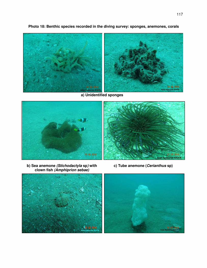
117
Photo 18: Benthic species recorded in the diving survey: sponges, anemones, corals
a) Unidentified sponges
b) Sea anemone (Stichodactyla sp) with clown fish (Amphiprion sebae)
c) Tube anemone (Cerianthus sp)

118
d) Dead piece of mushroom coral (Cycloseris cyclolites)
e) Soft coral (Dendronephthya sp) (bleached)
Photo 19: Benthic species recorded in the diving survey: gorgonians, molluscs, starfish
a) Purple gorgonian b) Pen shell (Pinna sp) with Hydroid colonies
c) Dead Indian bailer volute (Melo melo) with damselfish (Lepidozygus tapienosoma)
d) Starfish (Luidia sp)

119
e) Dead and decaying starfish f) Unidentified starfish
Photo 20: Benthic species recorded in the diving survey: sand dollars, sea urchins, sea cucumbers
a) Sand dollar on coarse sand with shell debris
b) Regular sea urchin (Salmacis virgulatus)

120
c) Sea cucumber (Bohadschia similis) d) Sea cucumber (Holothuria spinifera?)
281. Four of the species (the hard and soft coral, tube anemone Cerianthus sp, and the Gorgonians (sea whips or sea fans)) are protected under the national Fauna and Flora Protection Ordinance.93 According to local experts this is to prevent these and other species being exploited commercially by the marine aquarium industry supplying mainly overseas markets, with which there has been a lucrative trade by private individuals in the past.
7. Benthic infauna
282. Animals recorded by the diving survey were mainly those that live on the surface of the seabed, known as epifauna. There is also a vast array of animals that burrow into the sediment, including species that feed on organic matter in the sand, others that filter particles and microbes from the seawater, and predators that feed on other animals. Together these comprise the infauna, which is a very important and often overlooked element of the coastal ecosystem. Some previous studies have investigated infauna on the Jaffna peninsula, but these have focused mainly on the lagoons, and none were specific to the north-east coast.94, 95 A survey of the infauna of the project site was therefore conducted to examine this component of the benthic environment. 283. A Petersen grab was lowered from a boat at 18 stations in the same general location as the diving survey, with the stations located approximately equidistantly along three transects 3 km apart, perpendicular to the beach. The grab was lowered with the jaws held open by a catch bar, which is released when the grab hits the seabed. This allows the jaws to snap shut, biting into the sediment, which is retained within the jaws as the grab is hauled to the surface (Photo 21). The grab sampled a surface area of 250 cm2 down to a depth of approximately 10-15 cm, depending on the penetration of the jaws. Sediment from the grab was placed into containers on the boat, one per station. A 10% solution of formalin in seawater was added to each sample to fix
93 Fauna and Flora Protection (Amendment) Act No 22 of 2009, Published as a Supplement to Part II of the Gazette of
the Democratic Socialist Republic of Sri Lanka of April 24, 2009 (http://www.hrcsl.lk/PFF/LIbrary_Domestic_Laws/Legislation_related_to_Environment/Fauna%20and%20Flora%20Protection%20Act%2022%20of%202009.pdf)
94 De Silva P H D H (1964): New species and records of polychaeta from Ceylon. National Museums, Colombo, 537-563
95 Fernando D H (1977): Lamellibranchiate fauna of the Estuarine and Coastal Areas in Sri Lanka. Bulletin of the Fisheries Research Station, Ceylon, 27, 29-54
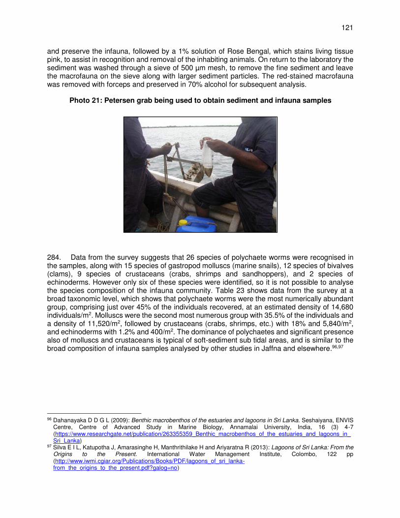
121
and preserve the infauna, followed by a 1% solution of Rose Bengal, which stains living tissue pink, to assist in recognition and removal of the inhabiting animals. On return to the laboratory the sediment was washed through a sieve of 500 µm mesh, to remove the fine sediment and leave the macrofauna on the sieve along with larger sediment particles. The red-stained macrofauna was removed with forceps and preserved in 70% alcohol for subsequent analysis.
Photo 21: Petersen grab being used to obtain sediment and infauna samples
284. Data from the survey suggests that 26 species of polychaete worms were recognised in the samples, along with 15 species of gastropod molluscs (marine snails), 12 species of bivalves (clams), 9 species of crustaceans (crabs, shrimps and sandhoppers), and 2 species of echinoderms. However only six of these species were identified, so it is not possible to analyse the species composition of the infauna community. Table 23 shows data from the survey at a broad taxonomic level, which shows that polychaete worms were the most numerically abundant group, comprising just over 45% of the individuals recovered, at an estimated density of 14,680 individuals/m2. Molluscs were the second most numerous group with 35.5% of the individuals and a density of 11,520/m2, followed by crustaceans (crabs, shrimps, etc.) with 18% and 5,840/m2, and echinoderms with 1.2% and 400/m2. The dominance of polychaetes and significant presence also of molluscs and crustaceans is typical of soft-sediment sub tidal areas, and is similar to the broad composition of infauna samples analysed by other studies in Jaffna and elsewhere.96,97
96 Dahanayaka D D G L (2009): Benthic macrobenthos of the estuaries and lagoons in Sri Lanka. Seshaiyana, ENVIS
Centre, Centre of Advanced Study in Marine Biology, Annamalai University, India, 16 (3) 4-7 (https://www.researchgate.net/publication/263355359_Benthic_macrobenthos_of_the_estuaries_and_lagoons_in_Sri_Lanka)
97 Silva E I L, Katupotha J, Amarasinghe H, Manthrithilake H and Ariyaratna R (2013): Lagoons of Sri Lanka: From the Origins to the Present. International Water Management Institute, Colombo, 122 pp (http://www.iwmi.cgiar.org/Publications/Books/PDF/lagoons_of_sri_lanka-from_the_origins_to_the_present.pdf?galog=no)
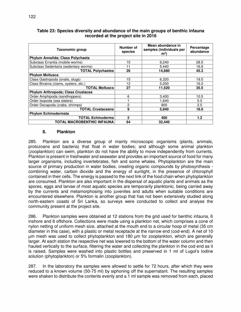
122
Table 23: Species diversity and abundance of the main groups of benthic infauna recorded at the project site in 2016
Taxonomic group Number of
species
Mean abundance in samples (individuals per
m2)
Percentage abundance
Phylum Annelida; Class Polychaeta Subclass Errantia (mobile worms) 15 9,240 28.5 Subclass Sedentaria (sedentary worms) 11 5,440 16.8
TOTAL Polychaetes 26 14,680 45.3 Phylum Mollusca Class Gastropoda (snails, slugs) 15 6,320 19.5 Class Bivalvia (clams, oysters, etc.) 12 5,200 16.0
TOTAL Molluscs 27 11,520 35.5
Phylum Arthropoda; Class Crustacea Order Amphipoda (sandhoppers) 6 3,400 10.5 Order Isopoda (sea slaters) 1 1,640 5.0 Order Decapoda (crabs, shrimps) 2 800 2.5
TOTAL Crustaceans 9 5,840 18.0
Phylum Echinodermata TOTAL Echinoderms 2 400 1.2
TOTAL MACROBENTHIC INFAUNA 64 32,440
8. Plankton
285. Plankton are a diverse group of mainly microscopic organisms (plants, animals, protozoans and bacteria) that float in water bodies; and although some animal plankton (zooplankton) can swim, plankton do not have the ability to move independently from currents. Plankton is present in freshwater and seawater and provides an important source of food for many larger organisms, including invertebrates, fish and some whales. Phytoplankton are the main source of primary production in water bodies, creating organic compounds by photosynthesis - combining water, carbon dioxide and the energy of sunlight, in the presence of chlorophyll contained in their cells. The energy is passed to the next link of the food chain when phytoplankton are consumed. Plankton are also important in the dispersal of aquatic plants and animals as the spores, eggs and larvae of most aquatic species are temporarily planktonic, being carried away by the currents and metamorphosing into juveniles and adults when suitable conditions are encountered elsewhere. Plankton is another group that has not been extensively studied along north-eastern coasts of Sri Lanka, so surveys were conducted to collect and analyse the community present at the project site. 286. Plankton samples were obtained at 12 stations from the grid used for benthic infauna, 6 inshore and 6 offshore. Collections were made using a plankton net, which comprises a cone of nylon netting of uniform mesh size, attached at the mouth end to a circular hoop of metal (35 cm diameter in this case), with a plastic or metal receptacle at the narrow end (cod-end). A net of 10 µm mesh was used to collect phytoplankton and 180 µm for zooplankton, which are generally larger. At each station the respective net was lowered to the bottom of the water column and then hauled vertically to the surface, filtering the water and collecting the plankton in the cod end as it is raised. Samples were washed into plastic bottles and preserved in 1 ml of Lugol’s Iodine solution (phytoplankton) or 5% formalin (zooplankton). 287. In the laboratory the samples were allowed to settle for 72 hours, after which they were reduced to a known volume (50-75 ml) by siphoning off the supernatant. The resulting samples were shaken to distribute the contents evenly and a 1 ml sample was removed from each, placed

123
onto a gridded Sedgwick-Rafter counting chamber,98 and examined by microscope under 10 x 10 magnification. Plankton genera and species were identified using standard keys,99,100,101 and sub-samples were enumerated by counting the number of individuals of each taxon within a set number of the gridded squares per sample.
98 Invented by William T Sedgwick and George W Rafter in 1889 in Massachusetts, USA, the Sedgwick-Rafter counting
cell is a shallow rectangular chamber on a modified microscope slide, which retains an exact volume of liquid (normally 1 ml) when the lid is applied, so that when microscopic contents are enumerated, the counts are based on a standard known volume of liquid. Some cells have a grid of equally-sized cells etched onto the base, allowing sub-samples (again of known volume) to be enumerated in the case of especially dense samples.
99 Newell G E & Newell R C (1963): Marine Plankton: A Practical Guide. Hutchinson Education Editions, London 100 Todd C D, Laverack M S and Boxshall G (1991): Coastal Marine Zooplankton: A Practical Manual for Students.
Cambridge University Press, 116 pp 101 Jayasiri H B (2009): A guide to the marine plankton of the Gulf of Mannar and Palk Strait, Sri Lanka. National Aquatic
Resources Research and Development Agency

124
Figure 36: Phytoplankton abundance (top), relative composition (middle) and species richness (bottom) at stations in the sub tidal area at the project site
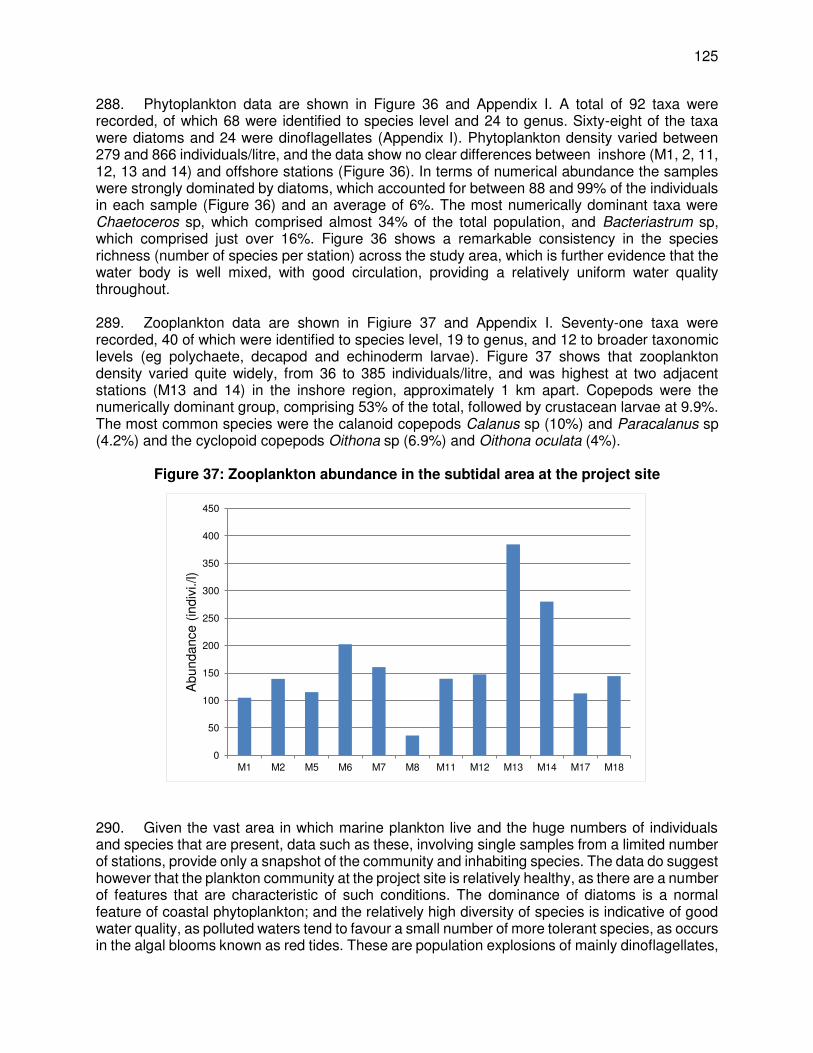
125
288. Phytoplankton data are shown in Figure 36 and Appendix I. A total of 92 taxa were recorded, of which 68 were identified to species level and 24 to genus. Sixty-eight of the taxa were diatoms and 24 were dinoflagellates (Appendix I). Phytoplankton density varied between 279 and 866 individuals/litre, and the data show no clear differences between inshore (M1, 2, 11, 12, 13 and 14) and offshore stations (Figure 36). In terms of numerical abundance the samples were strongly dominated by diatoms, which accounted for between 88 and 99% of the individuals in each sample (Figure 36) and an average of 6%. The most numerically dominant taxa were Chaetoceros sp, which comprised almost 34% of the total population, and Bacteriastrum sp, which comprised just over 16%. Figure 36 shows a remarkable consistency in the species richness (number of species per station) across the study area, which is further evidence that the water body is well mixed, with good circulation, providing a relatively uniform water quality throughout. 289. Zooplankton data are shown in Figiure 37 and Appendix I. Seventy-one taxa were recorded, 40 of which were identified to species level, 19 to genus, and 12 to broader taxonomic levels (eg polychaete, decapod and echinoderm larvae). Figure 37 shows that zooplankton density varied quite widely, from 36 to 385 individuals/litre, and was highest at two adjacent stations (M13 and 14) in the inshore region, approximately 1 km apart. Copepods were the numerically dominant group, comprising 53% of the total, followed by crustacean larvae at 9.9%. The most common species were the calanoid copepods Calanus sp (10%) and Paracalanus sp (4.2%) and the cyclopoid copepods Oithona sp (6.9%) and Oithona oculata (4%).
Figure 37: Zooplankton abundance in the subtidal area at the project site
290. Given the vast area in which marine plankton live and the huge numbers of individuals and species that are present, data such as these, involving single samples from a limited number of stations, provide only a snapshot of the community and inhabiting species. The data do suggest however that the plankton community at the project site is relatively healthy, as there are a number of features that are characteristic of such conditions. The dominance of diatoms is a normal feature of coastal phytoplankton; and the relatively high diversity of species is indicative of good water quality, as polluted waters tend to favour a small number of more tolerant species, as occurs in the algal blooms known as red tides. These are population explosions of mainly dinoflagellates,
0
50
100
150
200
250
300
350
400
450
M1 M2 M5 M6 M7 M8 M11 M12 M13 M14 M17 M18
Abu
ndan
ce (
indi
vi./l
)

126
so the low numbers of these organisms in the samples is another sign of a healthy community and unpolluted waters. The dominance of copepods in the zooplankton is also normal in coastal waters, and here again the diversity of species is a positive indicator.
9. Fish and fishing
291. Observations of the fish population of the study area were made during the diving survey described in Section V.B.7 above, and further information was obtained from interviews with two senior members of the local fishing community (see below). The diving survey noted that no schools of demersal or pelagic fish were seen in the area, and no commercially-exploited fish were reported in the lists of species encountered. Table 24 shows the fish that were recorded by the survey, and these are mainly small-sized species (length 15 cm or less), that are typical inhabitants of sandy areas of seabed. Some of these occur in association with other species; for example clownfish frequently live symbiotically102 with sea anemones, having developed immunity to the stinging tentacles, and those in the study area (Amphiprion sebae) were seen with the carpet anemone Stichodactyla sp. Cardinal fishes were found amongst clusters of dead pen shells (Pinna sp), possibly as an alternative to their preferred coral reef habitat, which is not present at this site. All of the gobies were seen in and around burrows they dig in the sand.
Table 24: Fish species observed during the diving survey at the project site
Phylum Family Species Common Name Observed
abundance at this site
Conservation status
Nat’l Global
Chordata Gobiidae Amblygobius sp Goby 7 - Occasional Mullidae Upeneus tragula Freckled goatfish 27 - Common LC Pomacentridae Lepidozygus tapeinosoma Damselfish Occasional Amphiprion sebae Sebae clownfish Occasional Apogonidae Cardinalfishes Occasional
Photo 22: Two of the fish species seen at the project site
a) Cardinalfish amongst pen shells, sponges and dead sand dollars (white)
b) Burrowing goby (Amblygobius sp)
102 Symbiosis is a close and often long-term interaction between two different species. In this case the relationship is
also mutualistic, where both species gain a benefit: clownfish are protected from predators by the stinging tentacles of the anemone, and the anemone gains nutrients from the clownfish faecal matter

127
292. Goatfish (Upeneus tragula) are members of the family Mullidae (red mullets), which are popular food-fish around the world. They are bottom-feeders, using their sensitive chin barbels to detect worms, crustaceans or molluscs in the surface sand, which they feed upon. Adults are captured by a variety of methods, including demersal nets and traps, and rod and line, but there is no fishery for small juvenile stages (<10 cm in length), such as those seen in the study area. These and all of the other fish species recorded during the survey are widely distributed and common around Sri Lankan coast, and none of the species is of any special conservation status. 293. Additional information on the fish and fisheries of the project area was obtained by interviewing the leader of the Madel fishermen of Maruthankerny-Thalaiyadi103 and the Treasurer of the Thalaiyadi Fisheries Society.104
103 Mr Thomas Arulanandan, owner of Madel fishing nets and leader of the Madel fishermen of Maruthankerny-
Thalaiyad.i 104 Mr K Mariyanayagam, Treasurer of Thalaiyadi Fisheries Society and Vice Secretary of the Rural Development
Society.

128
Photo 23: Interviews with senior members of the local fishing community
a) Leader of the Madel fishermen of Maruthankerny-Thalaiyadi
b) Treasurer of Thalaiyadi Fisheries Society
294. The Treasurer of Thalaiyadi Fisheries Society provided information on the range of different fishing methods used in the vicinity of the project site, which include:
(i) ‘Dappi’ traps set on the sandy seabed to catch slipper lobsters (Scyllaridae) and on offshore reefs to capture spiny lobsters (Palinuridae);
(ii) A bait fishery, harvesting squid from coastal and offshore waters to supply the deep-water tuna and bonito boats;
(iii) Divers harvesting sea cucumbers and chank (Turbinella pyrum), which has been excessive since the end of the war, and as a result the government has ceased issuing SCUBA permits for the Maruthankerny-Thalaiyadi coast;
(iv) Offshore fishing near the rock reefs for the larger predators: jacks (Carangidae), groupers (Serranidae) and snappers (Lutjanidae) using hand-lines, trolling (drawing baited lines behind a boat) and different types of net.
295. There is also a significant fishery harvesting large murex shells (Chicoreus ramosus) to obtain the flesh for export. Around 4 shells are needed to provide one kilogram of flesh, for which fishermen earn around SLR 500. The murex are captured using weighted nets that are allowed to remain on the seabed for 2-3 days to allow fish that become trapped in the net to die and decay, attracting the carnivorous murex and other molluscs to feed on the rotting flesh, becoming entangled in the process. The nets are rolled along the seabed by currents and entrap many other species that are not edible, and this unwanted bycatch is discarded on the beach when the nets are recovered. 296. A third informant, the operator of the boat used in the diving survey, who is also a local fisherman, explained that small beds of pen shells (Pinna sp) developed in the study area during the civil war when the Madel fishery did not operate regularly. However these have now been destroyed again by the resumed Madel fishing. This fishery, which appears to be more active in the area than previously thought, and the regular use of murex nets, rolling along the seabed entrapping fish, molluscs and crustaceans indiscriminately, would seem to explain the damage to benthic habitats and animals observed during the diving survey, and the quite barren appearance of the benthic and pelagic habitats. Local fishermen are aware of catches becoming reduced in the recent past, but attribute this to illegal trawling by vessels from India.
129
297. Existing Fishing Practice at the Site for Intake and Outfall. Intake is located 800 m off the coast while outfall is located 500 m off the coast in Thalaiyadi fishing village. As per the officials information from fisheries department, and community consultation with the fishermen in Thalaiyadi indicate that site is currently not used for any fishing. As in other coastal areas of Sri Lanka, traditional Ma Del (Beach seine) fishing is practiced in Thalaiyadi and other surrounding villages. Ma Del fishing is said to be the oldest fishing method practiced in Sri Lanka. Department of Fisheries and Aquatic Resources (DFAR) of Government of Sri Lanka (GoSL) based on the feasibility for Ma Del fishing, has allotted fishing sections (called Padu) in each village for the fishermen for this traditional labour intensive fishing for their livelihood. Based on traditional fishing rights, padus were officially allotted to fishermen and were notified via government gazette notification in 1985. These traditional fishing right is renewed every year, however, is non-transferable, and renewed only to the allotted traditional fishing family based on their application. Padus demarcated are exclusively for Ma Del fishing, and no other type of fishing activity is permitted in the coastal areas. Each padu is of 301 m wide, with a sea ward length of 1.5 nautical miles (~2.8 km) and about 45-200 m landward (on beach) depending on the availability of land. While seaward side is the fishing area for Ma Del fishing and landward side is required for preparatory, launching and harvesting activities. 298. In Thalaiyadi, there are 3 padus, of width 301 m each, which were allotted to 3 fishermen with traditional fishing rights. Of these 3, currently only one padu is in operation, that too intermittently, and the remaining 2 are non-operational since the 2004 tsunami. Before tsunami also the fishing was not regular. Various reasons, such as civil war, low fish production, non-availability of labour, migration to other areas for livelihood, preference to other comparatively low risk economic activities etc., have been attributed to this. The proposed intake and outfall (including the pipelines) are located in the unused padu in Thalaiyadi, where there is no fishing activity since 2004 Tsunami, and as per the traditional right owner of this padu, no fishing activity will be undertaken in future too. As the fishing right is non-transferable, there will be no fishing in this padu, and therefore consented to construct the intake in his traditional fishing right area. D. Biological Conditions – Along the Proposed Pumping Main Pipeline Alignment
299. Thalaiyadi area through which the pumping main pipeline is aligned is classified, floristically, as Coastal and Marine Belt Floristic Zone. Coastal mangroves, sand dunes and strand vegetation are the typical natural vegetation formations present in the area. Main ecological features of the proposed pipeline alignment area along Soranpattu-Thalaiyadi road (B-402) are the Thalaiyadi lagoon, mangrove forests, coastal sea, and sandy beach including small sand dunes. Man-made agricultural lands especially coconut plantations and paddy fields also dominant features in the area.
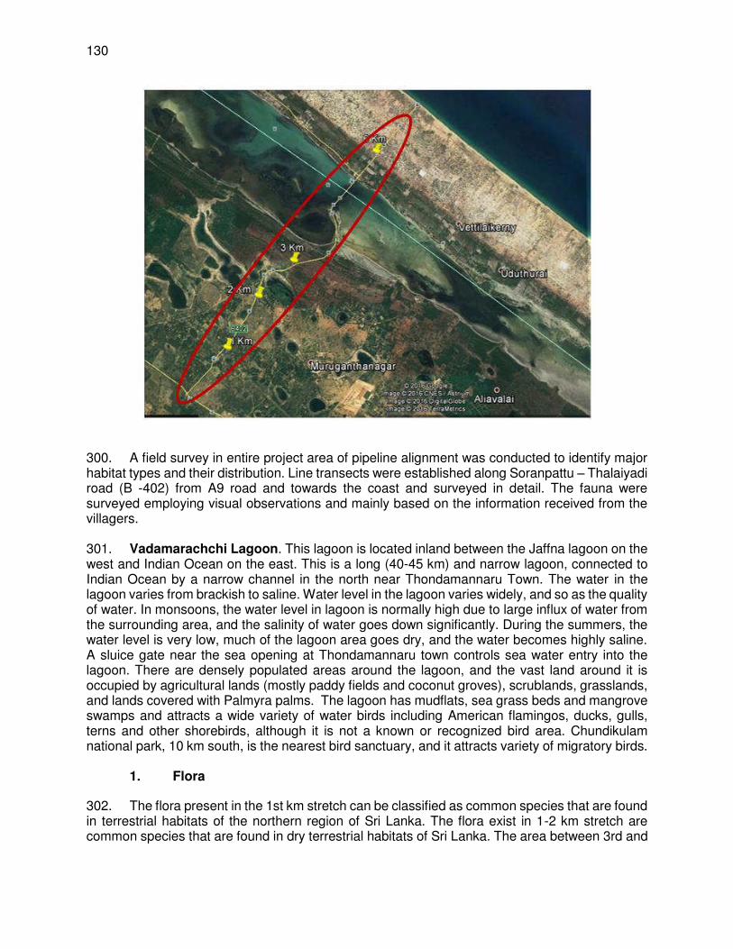
130
300. A field survey in entire project area of pipeline alignment was conducted to identify major habitat types and their distribution. Line transects were established along Soranpattu – Thalaiyadi road (B -402) from A9 road and towards the coast and surveyed in detail. The fauna were surveyed employing visual observations and mainly based on the information received from the villagers. 301. Vadamarachchi Lagoon. This lagoon is located inland between the Jaffna lagoon on the west and Indian Ocean on the east. This is a long (40-45 km) and narrow lagoon, connected to Indian Ocean by a narrow channel in the north near Thondamannaru Town. The water in the lagoon varies from brackish to saline. Water level in the lagoon varies widely, and so as the quality of water. In monsoons, the water level in lagoon is normally high due to large influx of water from the surrounding area, and the salinity of water goes down significantly. During the summers, the water level is very low, much of the lagoon area goes dry, and the water becomes highly saline. A sluice gate near the sea opening at Thondamannaru town controls sea water entry into the lagoon. There are densely populated areas around the lagoon, and the vast land around it is occupied by agricultural lands (mostly paddy fields and coconut groves), scrublands, grasslands, and lands covered with Palmyra palms. The lagoon has mudflats, sea grass beds and mangrove swamps and attracts a wide variety of water birds including American flamingos, ducks, gulls, terns and other shorebirds, although it is not a known or recognized bird area. Chundikulam national park, 10 km south, is the nearest bird sanctuary, and it attracts variety of migratory birds.
1. Flora
302. The flora present in the 1st km stretch can be classified as common species that are found in terrestrial habitats of the northern region of Sri Lanka. The flora exist in 1-2 km stretch are common species that are found in dry terrestrial habitats of Sri Lanka. The area between 3rd and

131
4th km mainly consists of paddy fields and the rest was scrubland. Few trees of Manilkarahexandra were observed. 303. The road crosses Vadamarachchi lagoon between 4th and 5th km, where a few patches of mangroves were found. Four true mangrove species were identified along the road in Thalaiyadi (Vadamarachchi lagoon). Lumnitzeraracemosa is the single predominant mangrove specie found beside the road nearby small islands in the lagoon. Avicennia marina, Rhizophoramucronata and Exoecariaagallocha spread as individual plants or isolated plants. Less diversity of mangrove species coincided with environmentally extreme conditions of the lagoon, such as atmospheric dryness, high salinity (>35 ppt) desiccating salt spray, perennially high temperature, excessive evaporation etc., do not attract some mangrove species. Further, high fluctuation of water salinity during dry and rainy season especially hyper saline and freshwater creates unfavourable condition for some mangrove species. Mangrove associated species such as Terminalia catappa, Phoenix frinifera and Premnaintegrifolia observed. A single tree of mature Pandanus tectorius was observed. However either mangrove species or the mangrove associated species present in the area are not considered as rare, endangered or endemic species in Sri Lanka. 304. In the rest of the alignment, Azadirachtaindica, Thespesiapopulnea, Borassusflabellifer and Vitexnegundo were found at the margins of the road and interior areas are cultivated paddy field mainly consists of Oriza sativa. Lantana camara, Abrusprecatorius and Phoenix frinifera exist in the area. No critical or sensitive habitats or flora were observed. There were no endemic, rear, vulnerable, threatened or critically scarce plant species were identified along the pipeline alignment (Soranpattu – Thalaiyadi Road).

132
Table 25: Flora species along the pipeline alignment Trees Smaller plants / weeds / shrubs /
herbaceous plants Commercially cultivated species
Azadirachtaindica. Bauhinia racemose Borassusflabellifer Cocos nucifera. Drypetessepiaria , Ficusbengaensis, Gmelina asiatica. Madhucalongifolia, Mangiferasp, Manilkarahexandra Moringaoleifera Opuntiasp Prospisjuliflora Syzygiumcumini Thespesiapopulnea, Mangroves Avicennia marina Lumnitzeraracemosa Rhizophoramucronata Exoecariaagallocha Mangroves associated species Abrusprecatorius, Calotropis gigantean Pandanus tectorius Phoenix frinifera Premnaintegrifolia Terminalia catappa, Vitexnegundo
Abrusprecatorius, Abutilon indicum, Aervalanata, Aponogtoncrispum, Asparagus sp. Avicennia marina Calotropis gigantean Carissa sp., Cassia fistula, Catharanthusroseus Calotropisgignata, Cuscutasp Eupatorium odoratum Flueggealeucopyrus Gloriosasuperba Gmelina asiatica, Lantana camara Mimosa pudica Ocimum sanctum Opuntiadillenii Pongamiapinnata Stachytarphetaindica, Syzygiumsp., Thespesiapopulnea Tribulusterrestris, Vitexnegundo Zizyphusmauritiana Zizyphusnapeca Zizyphusoenopila
Cocos Nucifera (coconut) Oriza sativa (paddy) Mangiferasp (mango).
2. Fauna
305. Reptiles. Most of the reptiles recorded below based on the information received from the villagers only. Varanussalvator and Varanusbengalensis are the only species observed during the survey. Except the Crocodylusporosus, all the other species mentioned in the Table are of conservation status - “least concern”. According to the information received from villagers, Echiscarinatus, Varanusbengalensis and Varanussalvator are not a common or frequently visible species in the area. Crocodylus porosusis considered as a “near threatened” species in Sri Lanka (IUCN Red List – 2007). Amphibians were not observed or identified during the field visits.
Table 26: Reptilians recorded from Thalaiyadi – Soranpattu area. No Scientific Name Common Name Occurrence IUCN classification
1 Varanussalvator Water monitor Common LC 2 Varanusbengalensis Land monitor Common LC 3 Crocodylusporosus* Estuarine crocodile Quite rare LC 4 Calotes versicolor* Common garden
lizard Common -
5 Calotescalote* Green garden lizard Rare - 6 Mabuyacarinata* Common skink Common LC 7 NajaNaja* Cobra Quite rare LC 8 Ptyasmucoses* The common rat
snake Quite rare LC
9 Daboiarusselii* Russell’s viper Quite rare LC 10 Echiscarinatus* Saw scale viper Quite rare LC
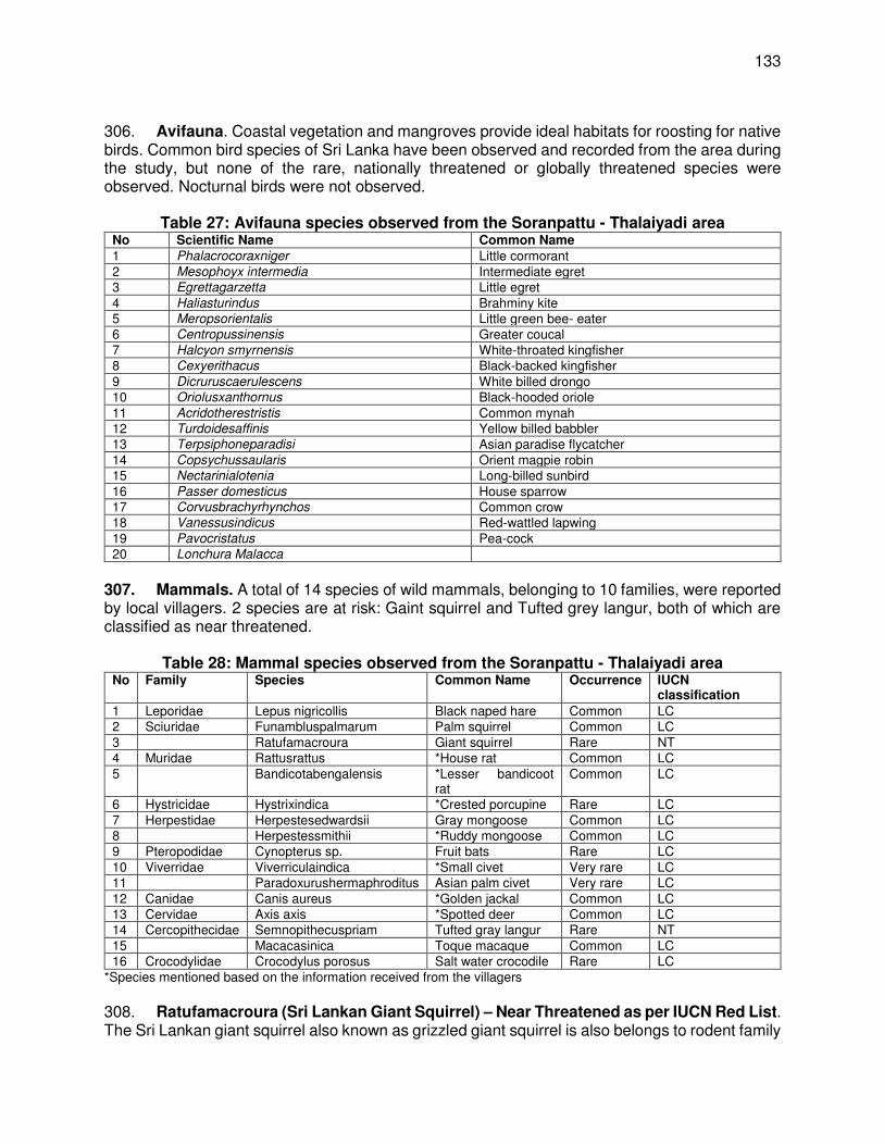
133
306. Avifauna. Coastal vegetation and mangroves provide ideal habitats for roosting for native birds. Common bird species of Sri Lanka have been observed and recorded from the area during the study, but none of the rare, nationally threatened or globally threatened species were observed. Nocturnal birds were not observed.
Table 27: Avifauna species observed from the Soranpattu - Thalaiyadi area No Scientific Name Common Name
1 Phalacrocoraxniger Little cormorant 2 Mesophoyx intermedia Intermediate egret 3 Egrettagarzetta Little egret 4 Haliasturindus Brahminy kite 5 Meropsorientalis Little green bee- eater 6 Centropussinensis Greater coucal 7 Halcyon smyrnensis White-throated kingfisher 8 Cexyerithacus Black-backed kingfisher 9 Dicruruscaerulescens White billed drongo 10 Oriolusxanthornus Black-hooded oriole 11 Acridotherestristis Common mynah 12 Turdoidesaffinis Yellow billed babbler 13 Terpsiphoneparadisi Asian paradise flycatcher 14 Copsychussaularis Orient magpie robin 15 Nectarinialotenia Long-billed sunbird 16 Passer domesticus House sparrow 17 Corvusbrachyrhynchos Common crow 18 Vanessusindicus Red-wattled lapwing 19 Pavocristatus Pea-cock 20 Lonchura Malacca
307. Mammals. A total of 14 species of wild mammals, belonging to 10 families, were reported by local villagers. 2 species are at risk: Gaint squirrel and Tufted grey langur, both of which are classified as near threatened.
Table 28: Mammal species observed from the Soranpattu - Thalaiyadi area
No Family Species Common Name Occurrence IUCN classification
1 Leporidae Lepus nigricollis Black naped hare Common LC 2 Sciuridae Funambluspalmarum Palm squirrel Common LC 3 Ratufamacroura Giant squirrel Rare NT 4 Muridae Rattusrattus *House rat Common LC 5 Bandicotabengalensis *Lesser bandicoot
rat Common LC
6 Hystricidae Hystrixindica *Crested porcupine Rare LC 7 Herpestidae Herpestesedwardsii Gray mongoose Common LC 8 Herpestessmithii *Ruddy mongoose Common LC 9 Pteropodidae Cynopterus sp. Fruit bats Rare LC 10 Viverridae Viverriculaindica *Small civet Very rare LC 11 Paradoxurushermaphroditus Asian palm civet Very rare LC 12 Canidae Canis aureus *Golden jackal Common LC 13 Cervidae Axis axis *Spotted deer Common LC 14 Cercopithecidae Semnopithecuspriam Tufted gray langur Rare NT 15 Macacasinica Toque macaque Common LC 16 Crocodylidae Crocodylus porosus Salt water crocodile Rare LC
*Species mentioned based on the information received from the villagers 308. Ratufamacroura (Sri Lankan Giant Squirrel) – Near Threatened as per IUCN Red List. The Sri Lankan giant squirrel also known as grizzled giant squirrel is also belongs to rodent family

134
Sciuridae. Giant squirrel is endemic to southern India and Sri Lanka and considered as a near threatened species in IUCN global list of Threatened Species especially considering Indian population due to its restricted distribution, small population size and anthropogenic pressure to its natural habitats. In Sri Lanka they are found in the highlands of the Central and Uva Provinces but never reported from Northern Province. 309. Semnopithecuspriam (Gray Langur) – Near Threatened as per IUCN. The gray langur belongs to the family Cercopithecidaeand is found in southeast India and Sri Lanka. They are commonthroughout the country’s dry zone forests, road sides and also within human dwellings. Many numerous troops are found at archeologically important areas, such as Polonnaruwa, Dambulla, Anuradhapura and Sigiriya. The animal is also found in southward of the island, such as Hambntota, Yala National Park and Tissamaharama. IUCN has Listed Semnopithecuspriamas Near Threatened because of widespread habitat loss and hunting through much of its range.
3. Plankton in Vadamarachchi Lagoon
310. Zooplankton & Phytoplankton. The diversity of zooplankton and phytoplankton species in Thalaiyadi lagoon is very limited compared with other coastal lagoons in Sri Lanka. The species composition is almost totally confined to protozoans, coelenterates, arthropods and molluscs and specially crustaceans and their larval stages, gastropods and bivalves. Zooplankton samples were collected using plankton net with a mesh size of 100µm and a net mouth area of 0.07 m2. The filtered samples were washed into the sterilized collecting bottles and immediately fixed in 5% formalin. Identification was done by using plankton keys by Todd et al. (1996) and Omori and Ikeda (1984). 311. Copepods found to be the most dominant zooplankton group which comprised of 52 % of the zooplankton community of the lagoon (see Chart). Paracalanus sp. Calanusfinmarchicus and Oithana sp. were the major contributors of the copepod community. Diatoms, dinoflagellates and filamentous algae were the major dominant phytoplankton groups in the lagoon. The most abundance diatom genus was Navicula sp., Thalassionemasp. and Spirogyra sp. were the dominant forms of filamentous algae found in the lagoon.
4. Fish in Vadamarachchi Lagoon
312. A total of10 brackish water fish species were recorded from the lagoon together with one shrimp specie Penaeus indicus (Table 29). Fishery is not a major livelihood activity in the Thalaiyadi lagoon since the lagoon become almost dry during the half of the year. Fish were harvested by very few numbers of fishermen in the area by using Theppam, a traditional fishing fleet and non-motorized small fibre glass canoes. Hypersaline condition and low water level/or
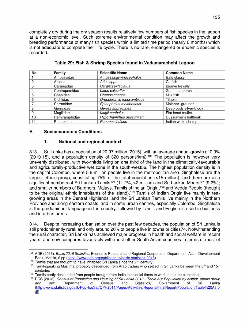
135
completely dry during the dry season results relatively few numbers of fish species in the lagoon at a non-economic level. Such extreme environmental condition may affect the growth and breeding performance of many fish species within a limited time period (nearly 6 months) which is not adequate to complete their life cycle. There is no rare, endangered or endemic species is recorded.
Table 29: Fish & Shrimp Species found in Vadamarachchi Lagoon
No Family Scientific Name Common Name
1 Ambassidae Ambassisgymnocephalus Bald glassy 2 Ariidae Arius spp. Catfish 3 Carangidae Caranxsexfaciatus Bigeye trevally 4 Centropomidae Lates calcarifer Giant sea perch 5 Chanidae Chanos chanos Milk fish 6 Cichlidae Oreochromis mossambicus Tilapia 7 Serranidae Epinephelus malabaricus Malabar grouper 8 Gerreidae Gerres abbreviates Deep body silver-biddy 9 Mugilidae Mugil cephalus Flat head mullet 10 Hemiramphidae Hyporhamphus dussumieri Dussumier’s halfbeak 11 Penaeidae Penaeus indicus Indian white shrimp
E. Socioeconomic Conditions
1. National and regional context
313. Sri Lanka has a population of 20.97 million (2015), with an average annual growth of 0.9% (2010-15), and a population density of 320 persons/km2.105 The population is however very unevenly distributed, with two-thirds living on one third of the land in the climatically-favourable and agriculturally-productive wet zone in the south-west56. The highest population density is in the capital Colombo, where 5.6 million people live in the metropolitan area. Singhalese are the largest ethnic group, constituting 75% of the total population (>15 million); and there are also significant numbers of Sri Lankan Tamils106 (11.2%, >2 million) and Sri Lankan Moors107 (9.2%); and smaller numbers of Burghers, Malays, Tamils of Indian Origin,108 and Vedda People (thought to be the original ethnic inhabitants of the island).109 Tamils of Indian Origin live mainly in tea-growing areas in the Central Highlands, and the Sri Lankan Tamils live mainly in the Northern Province and along eastern coasts, and in some urban centres, especially Colombo. Singhalese is the predominant language in the country, followed by Tamil; and English is used in business and in urban areas. 314. Despite increasing urbanisation over the past few decades, the population of Sri Lanka is still predominantly rural, and only around 20% of people live in towns or cities74. Notwithstanding the rural character, Sri Lanka has achieved major progress in health and social welfare in recent years, and now compares favourably with most other South Asian countries in terms of most of
105 ADB (2016): Basic 2016 Statistics. Economic Research and Regional Cooperation Department, Asian Development
Bank, Manila, 6 pp (https://www.adb.org/publications/basic-statistics-2016) 106 Tamils that are thought to have inhabited Sri Lanka since the 2nd century 107 Tamil-speaking Muslims, probably descended from Arab traders who settled in Sri Lanka between the 8th and 15th
centuries 108 Tamils partly descended from people brought from India in colonial times to work in the tea plantations 109 DCS (2012): Census of Population and Housing of Sri Lanka 2012 - Table A3: Population by district, ethnic group
and sex. Department of Census and Statistics, Government of Sri Lanka (http://www.statistics.gov.lk/PopHouSat/CPH2011/Pages/Activities/Reports/FinalReport/Population/Table%20A3.pdf)

136
the common indicators. These include: life expectancy of 72 years in males and 77 in females; infant mortality of 8 per 1,000 live births; maternal mortality of 0.3 per 1,000 (both 2015); net enrolment in primary education of 97.3%; literacy rate of 98.8% in 15-24 year-olds; an almost total eradication of malaria (32 cases per 100,000 population in 2012, with no deaths); and a reduction in tuberculosis to 65 per 100,000 people in 2014, with 6 deaths.91 Major factors in these figures are the establishment of a universal “pro-poor” health system offering free treatment for all; free education up to and including university level; food subsidies for those on lower incomes; and subsidised credit to help raise living standards74. 315. Sri Lanka’s economy has been buoyant in the period since the end of the civil war, when the Government’s drive towards reconstruction and development has stimulated economic growth of 6.4% between 2010 and 2015. In this period the country has transitioned from a prominently agricultural base towards a more urbanised economy, driven by the service sector, which accounted for 62.4% of GDP in 2015, followed by manufacturing (28.9%) and agriculture (8.7%).110 Economic growth has led to improved socioeconomic conditions, as Per Capita Income increased from US$ 1,000 in 200456 and $2,000 in 200974, to $3,924 in 201596. Increased household income has stimulated lifestyle changes, and expenditure is now proportionally less on food and more on communication, education, recreation, housing and utilities. Over 70% of houses are now built of brick or cement, with tiled or sheeted roofing74; 95% of the population has access to sanitation; 96% use improved drinking water sources; and cellular telephone subscriptions are 1.03 per head of population91. Poverty has declined accordingly, and in 2013, 4.2 % of employed people and 6.7 % of the population as a whole were living in extreme poverty, on less than $1.90 per day91. However around 15% of the population (over 3 million people) remain in moderate poverty, surviving on less than $3.10 per day; and there are persistent pockets of poverty, especially in the north and east of the country, and in the estate sector96. 316. Administratively Sri Lanka is divided into nine provinces, of which the Northern Province is the third largest at 8,848 km2, but currently has the lowest population (1,241,173 in December 2015)111 and the second lowest population density (140 persons/km2). Much of the civil war was centred on the Northern and Eastern provinces, where the economy and social conditions suffered greatly as a result. Population numbers are low because of war casualties and because hundreds of thousands of Tamils migrated overseas to escape the conflict; and others moved to safer parts of Sri Lanka, especially Colombo. Infrastructure was heavily damaged during the fighting, and the area did not receive the levels of government investment that might otherwise have been made. The tsunami of 2004 exacerbated these issues and created others: increasing the death toll by over 30,000 and the number of displaced persons by half a million; damaging coastal infrastructure; and severely damaging the economy by destroying crops, rendering large areas of agricultural land unusable because of salinization, and discouraging tourism which is a mainstay of local incomes. With international support the Government responded effectively to both events: rehousing most of those displaced by the tsunami; increasing investment in public and social infrastructure in war-affected areas; and re-establishing safe and peaceful conditions, which has encouraged large numbers of people to return. 317. The Northern Province is divided into five districts, each administered by a District Secretariat. Jaffna District, in which this project is located, covers 1,012 km2, which is most of Jaffna Peninsula, except for an area of approximately 140 km2 on the southern side of
110 World Bank (2016): Sri Lanka Overview. The World Bank, Washington
(http://www.worldbank.org/en/country/srilanka/overview) 111 NPC (2016): Vital Statistics - 2015. Office of the Deputy Chief Secretary - Planning, Northern Provincial Council
(https://www.np.gov.lk/pdf/CSCluster/vital%202016.pdf)

137
Vadamarachchi Lagoon, which is part of Kilinochchi District. The current population of Jaffna District is 618,209 (December 2015)97, living in 190,993 households; and there is a sex ratio112 of 92.5, because of a higher proportion of male deaths in the civil war. As a result there are a large number of households that are headed by women (currently 27,756 families, according to data from the District Secretariat; and 8.5% of the female family heads are under 40 years of age).113 318. The Northern Province has not yet seen the economic changes that have occurred elsewhere in Sri Lanka and agriculture is still the main economic driver. Around one third of households in Jaffna District are engaged solely in agriculture, and the main crops are red onion, chillies, potatoes, other vegetables, tobacco, banana and grapes, all of which are cultivated commercially throughout the year; and paddy rice, grown under rain-fed irrigation during the north-east monsoon in September to March (known as the maha season). Other important crops include pulses, coconut and Palmyra palm; and most families also cultivate home gardens for their own needs99. Fishing is the second most important economic activity, supporting over 20,000 families and contributing around 6% to the national fish production. Other sources of employment include provincial and national government offices in Jaffna City (currently employing almost 30,000 people), skilled trades (masons, carpenters, electricians, etc. - 20,000) and the private sector (>12,000).114 The District Secretariat records the occupations of 174,080 people, which suggests that there are some households without any formal employment. Some of these may be sustained by remittances from family members overseas; and some will supplement subsistence agriculture by income from casual work when available. But this must leave some households near or below the poverty level when paid work is not available.
2. Vadamarachchi East and Maruthankerny
319. Jaffna District is divided into 15 Divisional Secretary Divisions (DS Divisions), of which Vadamarachchi East covers most of the eastern coastal zone, between Elephant Pass and Vadamarachchi lagoons and the sea (Figure 38). This is the second-largest DS Division in Jaffna, with an area of 153 km2, but it is one of the least populated, with a total of only 16,102 inhabitants115 and a population density of 105 persons/km2. This is largely because of the remote nature of the area (distant from the district capital Jaffna City and served only by a B-class road) and the general unsuitability of the saline sandy soils for commercial agriculture. Because of this, fishing is the main occupation, followed by small- scale agriculture, which is practiced where conditions allow. The 16,102 inhabitants live in 5023 families, so the average family size of 3.2 is below the national average of 3.8.116
112 Sex ratio is the ratio of males to females in a population. A value of 100 is the normal 1:1 ratio, and a value of <100
means there are more females than males 113 Jaffna District Secretariat (2016): About Jaffna District: A Glance at Jaffna District.
(http://www.jaffna.dist.gov.lk/index.php?option=com_content&view=article&id=98&Itemid=221&lang=en) 114 Jaffna District Secretariat (2016): Statistical Information: Population.
(http://www.jaffna.dist.gov.lk/index.php?option=com_content&view=article&id=145&Itemid=244&lang=en) 115 Vadamaradchy East Divisional Secretariat (2016): Division Details: Population.
(http://www.vadamarachieast.ds.gov.lk/index.php?option=com_content&view=article&id=55&Itemid=163&lang=en) 116 DCS (2012): Census of Population and Housing - 2013, Sri Lanka: Population Tables. Department of Census and
Statistics, Colombo (http://www.statistics.gov.lk/PopHouSat/CPH2011/Pages/Activities/Reports/FinalReport/Population/FinalPopulation.pdf)

138
Figure 38: Local government administration in the project area: Jaffna District Divisional Secretary Divisions (top); Vadamarachchi East Grama Niladhari Divisions (bottom)
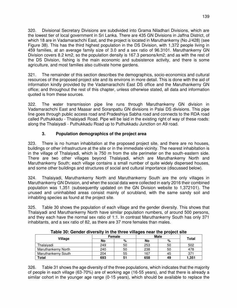
139
320. Divisional Secretary Divisions are subdivided into Grama Niladhari Divisions, which are the lowest tier of local government in Sri Lanka. There are 435 GN Divisions in Jaffna District, of which 18 are in Vadamarachchi East, and the project is located in Maruthankerny (No J/428) (see Figure 38). This has the third highest population in the DS Division, with 1,372 people living in 459 families, at an average family size of 3.0 and a sex ratio of 96.3101. Maruthankerny GN Division covers 8.2 km2, so the population density is 167.3 persons/km2; and as with the rest of the DS Division, fishing is the main economic and subsistence activity, and there is some agriculture, and most families also cultivate home gardens. 321. The remainder of this section describes the demographics, socio-economics and cultural resources of the proposed project site and its environs in more detail. This is done with the aid of information kindly provided by the Vadamarachchi East DS office and the Maruthankerny GN office; and throughout the rest of this chapter, unless otherwise stated, all data and information quoted is from these sources. 322. The water transmission pipe line runs through Maruthankerny GN division in Vadamarachchi East and Maasar and Soranpattu GN divisions in Palai DS divisions. This pipe line goes through public access road and Pradeshiya Sabha road and connects to the RDA road called Puthukkadu - Thalaiyadi Road. Pipe will be laid in the existing right of way of these roads: along the Thalaiyadi - Puthukkadu Road up to Puthukkadu Junction on A9 road.
3. Population demographics of the project area
323. There is no human inhabitation at the proposed project site, and there are no houses, buildings or other infrastructure at the site or in the immediate vicinity. The nearest inhabitation is in the village of Thalaiyadi, which is 750 m from the site perimeter on the south-eastern side. There are two other villages beyond Thalaiyadi, which are Maruthankerny North and Maruthankerny South; each village contains a small number of quite widely dispersed houses, and some other buildings and structures of social and cultural importance (discussed below). 324. Thalaiyadi, Maruthankerny North and Maruthankerny South are the only villages in Maruthankerny GN Division, and when the social data were collected in early 2016 their combined population was 1,351 (subsequently updated on the GN Division website to 1,372101). The unused and uninhabited areas consist mainly of scrubland, with the same sandy soil and inhabiting species as found at the project site. 325. Table 30 shows the population of each village and the gender diversity. This shows that Thalaiyadi and Maruthankerny North have similar population numbers, of around 500 persons, and they each have the normal sex ratio of 1:1. In contrast Maruthankerny South has only 371 inhabitants, and a sex ratio of 82, as there are 37 more females than males.
Table 30: Gender diversity in the three villages near the project site
Village Female Male
Total No % No %
Thalaiyadi 249 50 253 50 502 Maruthankerny North 240 50 238 50 478 Maruthankerny South 204 55 167 45 371 Total 693 51 658 49 1,351
326. Table 31 shows the age diversity of the three populations, which indicates that the majority of people in each village (63-70%) are of working age (16-55 years), and that there is already a similar cohort in the younger age range (0-15 years), which should be available to replace the

140
productive group as they become older and retire in the future. This is a relatively normal population distribution, although the significantly lower numbers of people in the older age range (> 55 years) suggests that life expectancy is lower than the national average, possibly because of the strenuous manual labour involved in fishing and agriculture, and the inherent dangers of working at sea.
Table 31: Age distribution of the population in the three local villages
Village Proportion of the population in each age group
Total 0-15 years 16-30 years 31-55 years >55 years
No % No % No % No %
Thalaiyadi 125 25 151 30 186 37 40 8 502 Maruthankerny North 129 27 134 28 167 35 48 10 478 Maruthankerny South 85 23 115 31 145 39 26 7 371 Total 339 25 400 30 498 37 114 8 1,351
327. There is no ethnic diversity in these villages as the entire population is Sri Lankan Tamil. There is also little religious diversity within individual villages, but there are quite notable differences between the villages. Table 32 shows that all of the people in Thalaiyadi are Christian, of the Roman Catholic faith, whereas 90% of the population of Maruthankerny North and South are Hindu, and only 10% are Roman Catholic.
Table 32: Religious diversity in the three local villages
Village Buddhist Hindu Catholic
Total No % No % No %
Thalaiyadi 0 0 0 0 502 100 502 Maruthankerny North 0 0 430 90 48 10 478 Maruthankerny South 0 0 334 90 37 10 371 Total 0 0 764 57 587 43 1,351
4. Socioeconomics
328. In common with much of the rest of Vadamarachchi East DS Division, fishing is the main occupation in these villages, supporting all of the families in Thalaiyadi, 90% of those in Maruthankerny North and 60% of those in Maruthankerny South. The remaining households are engaged in agriculture, and both occupations are relatively low-yielding in economic terms because of a number of factors, including the limited use of mechanised fishing vessels and techniques, and the limited rainfall and largely unsuitable soils for agriculture. As a result the community is not prosperous, and most families have little disposable income. 329. Anecdotal evidence suggests that educational standards are lower than in the more urban parts of Jaffna, where there has been more investment in post-war rehabilitation, including provision of improved educational resources. There are two schools in Maruthankerny GN Division: one limited to primary education, which serves only 40 students at present; and a second school offering classes up to GCE Ordinary Level, with a student population of 227. Students have to travel inland for Advanced Level schooling and to Jaffna City to attend university, and few families have the necessary resources. 330. This area also suffered during the civil war, when 19-20 people were killed and another 19 were injured, and more significantly from the tsunami when 60 or more people were killed, and all of the houses in Thalaiyadi and Maruthankerny North were destroyed. Both villages have been rebuilt approximately 300 m inland of the original locations, and each family has been given a

141
new house and a plot of land of 750-1,000 m2 (30-40 sq perch), which many residents say is much smaller than the land plots they owned previously. 331. The Economic Activities in Vicinity of Project Implementing Area. The main economic activity of the people in this GN division is fishing (85% of total families), comprises of three villages. The project is located in the jurisdiction of Thalaiyadi village where all the families of this village are involved in fishing operations. In the other two villages Maruthankerny North and Maruthankerny south 90 % and 60% of the working age population is involved in fishing activities as their main source of livelihood. Rest of the families in these villages are engaged in labour work (in other areas paddy fields and other crop fields in highlands). 332. The Chempionpattu GN division is located northwest side of the intake area, about 2 km from the boundary of outfall and intake area. However, as per the Fisheries Department, some of the fishermen who are landing their boats in the area situated about 2.5 km from the intake area are involved in fishing activities in the vicinity of the project implementing area (sea area). The Chempionpattu GN division has 416 families of which 320 (77%) are involved in fishing activity. The rest of the families are dependent on limited agriculture activities in their home gardens, and others are in various modes of self-employment. 333. The section of the water transmission line (section from Puthukkadu junction on A9 road) is falling within 2 GN divisions of Palai DS division- Maasar and Soranpattu. The people in these 2 GN divisions are mainly from the agricultural community and some are employed in other activities. There are no people involved in fishery activities in these 2 GN divisions. Economic use and economic activities on the proposed project sites and surroundings are detailed below:
(i) SWRO plant land. this land in extent of about 5 hectares (ha) is not used for any economic or other livelihood activities. It is free of any encumbrances and only has scrub vegetation. It is public land which comes under the preview of Vadamarachchi East Division Secretariat.
(ii) The coastal belt between sea and the SWRO plant land.117 This belt of land does not have any human settlements or other economic activities. This stretch only has one access road which connects to Chempionpattu Grama Niladhari division.
(iii) Potable water conveyance main. This pipeline will be laid in the right of way of public roads. The area in the RoWs is free from encumbrances and is not used for any economic activity.118 Some 25 shops are located along this alignment. The head section of the water transmission line (section from Puthukkadu junction on A9 road) is falling within 2 Grama Niladhari divisions of Palai Divisional Secretariat division- Maasar and Soranpattu. The entire Maasar Grama Niladhari division can be regarded as an agricultural area. The major crop grown is coconut, which is grown in home gardens and other high lands. The land use in Soranpattu Grama Niladhari division is similar to land use in Maasar Grama Niladhari division. Most of the families are involved in coconut cultivation. The people in these 2 Grama Niladhari divisions are mainly from the agricultural community and some are employed in other activities. There are no people involved in fishery activities in these 2 Grama Niladhari divisions.
117 This is the stretch of land between SWRO plant land and the beach area where madal padus are designated. 118 The field survey findings indicate that all the structures along the transmission pipe alignment are located more than
2 m away from the edge of the public roads.
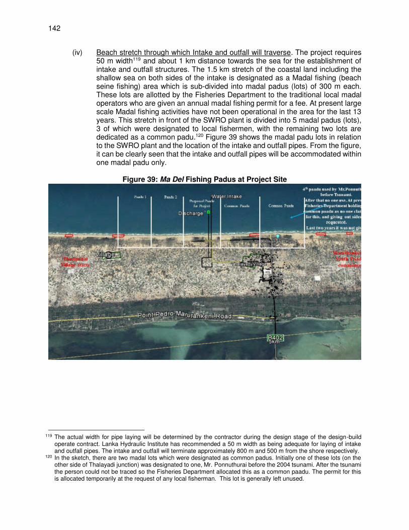
142
(iv) Beach stretch through which Intake and outfall will traverse. The project requires 50 m width119 and about 1 km distance towards the sea for the establishment of intake and outfall structures. The 1.5 km stretch of the coastal land including the shallow sea on both sides of the intake is designated as a Madal fishing (beach seine fishing) area which is sub-divided into madal padus (lots) of 300 m each. These lots are allotted by the Fisheries Department to the traditional local madal operators who are given an annual madal fishing permit for a fee. At present large scale Madal fishing activities have not been operational in the area for the last 13 years. This stretch in front of the SWRO plant is divided into 5 madal padus (lots), 3 of which were designated to local fishermen, with the remaining two lots are dedicated as a common padu.120 Figure 39 shows the madal padu lots in relation to the SWRO plant and the location of the intake and outfall pipes. From the figure, it can be clearly seen that the intake and outfall pipes will be accommodated within one madal padu only.
Figure 39: Ma Del Fishing Padus at Project Site
119 The actual width for pipe laying will be determined by the contractor during the design stage of the design-build
operate contract. Lanka Hydraulic Institute has recommended a 50 m width as being adequate for laying of intake and outfall pipes. The intake and outfall will terminate approximately 800 m and 500 m from the shore respectively.
120 In the sketch, there are two madal lots which were designated as common padus. Initially one of these lots (on the other side of Thalayadi junction) was designated to one, Mr. Ponnuthurai before the 2004 tsunami. After the tsunami the person could not be traced so the Fisheries Department allocated this as a common paadu. The permit for this is allocated temporarily at the request of any local fisherman. This lot is generally left unused.
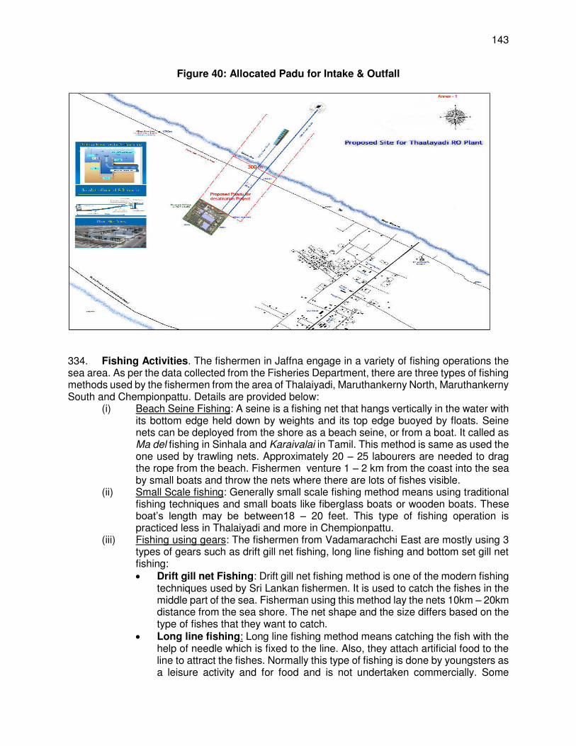
143
Figure 40: Allocated Padu for Intake & Outfall
334. Fishing Activities. The fishermen in Jaffna engage in a variety of fishing operations the sea area. As per the data collected from the Fisheries Department, there are three types of fishing methods used by the fishermen from the area of Thalaiyadi, Maruthankerny North, Maruthankerny South and Chempionpattu. Details are provided below:
(i) Beach Seine Fishing: A seine is a fishing net that hangs vertically in the water with its bottom edge held down by weights and its top edge buoyed by floats. Seine nets can be deployed from the shore as a beach seine, or from a boat. It called as Ma del fishing in Sinhala and Karaivalai in Tamil. This method is same as used the one used by trawling nets. Approximately 20 – 25 labourers are needed to drag the rope from the beach. Fishermen venture 1 – 2 km from the coast into the sea by small boats and throw the nets where there are lots of fishes visible.
(ii) Small Scale fishing: Generally small scale fishing method means using traditional fishing techniques and small boats like fiberglass boats or wooden boats. These boat’s length may be between18 – 20 feet. This type of fishing operation is practiced less in Thalaiyadi and more in Chempionpattu.
(iii) Fishing using gears: The fishermen from Vadamarachchi East are mostly using 3 types of gears such as drift gill net fishing, long line fishing and bottom set gill net fishing: Drift gill net Fishing: Drift gill net fishing method is one of the modern fishing
techniques used by Sri Lankan fishermen. It is used to catch the fishes in the middle part of the sea. Fisherman using this method lay the nets 10km – 20km distance from the sea shore. The net shape and the size differs based on the type of fishes that they want to catch.
Long line fishing: Long line fishing method means catching the fish with the help of needle which is fixed to the line. Also, they attach artificial food to the line to attract the fishes. Normally this type of fishing is done by youngsters as a leisure activity and for food and is not undertaken commercially. Some

144
fishermen catch the fish through long lining method from the sea shore while some are going by boat and catching fishes 20km – 30km away from the sea shore.
A bottom-set gillnet has heavy sinkers on the lead line to keep it on the bottom and is set in one place either by having anchors at both ends or by tying one end of the net to something on land.
Figure 41: Main Types of Fishing in Project Area
Beach seine (ma del) fish net Ma del fishing Traditional fishing with boats
Gillnet fishing Gillnet fishing Long-line fishing
335. As in other coastal areas of Sri Lanka, traditional Ma Del (Beach seine) fishing, which is carried out in shallow waters near the coast by marginal fishermen, is practiced in Thalaiyadi and other surrounding villages. Ma Del fishing is said to be the oldest fishing method practiced in Sri Lanka. Nets are thrown in the shallow sea, which move with the sea current. Department of Fisheries and Aquatic Resources (DFAR) of Government of Sri Lanka (GoSL) based on the feasibility for Ma Del fishing, has allotted fishing sections (called Padu) in each village for the fishermen for this traditional labour intensive fishing for their livelihood. Based on traditional fishing rights, padus were officially allotted to fishermen and were notified via government gazette notification in 1985. These traditional fishing right is renewed every year, however, is non-transferable, and renewed only to the allotted traditional fishing family based on their application. Besides, there are common padus designated by the Department for the common use in respective fishing village. 336. Padus demarcated are exclusively for Ma Del fishing, and no other type of fishing activity is permitted in the coastal areas. Each padu is of 301 m wide, with a sea ward length of 1.5 nautical miles (~2.8 km) and about 45-200 m landward (on beach) depending on the availability of land. While seaward side is the fishing area for Ma Del fishing and landward side is required for preparatory, launching and harvesting activities. 337. In Thalaiyadi, there are 3 padus, of width 301 m each, which were allotted to 3 fishermen with traditional fishing rights, and a common padu. Besides there are 2 common padus as

145
explained earlier. Proposed intake and outfall is located in a padu, which is between common padu and another adjoining padu (Figure 42). In Chempionpattu and Maruthankerny North fishing villages, located on either side of the intake bordering village Thalaiyadi, there are 15 and 3 padus respectively for ma del fishing.
Figure 42: Ma Del Fishing Padus at Project Site
338. For the last 13 years, since 2004 Tsunami, Ma del Fishing is not operational in large scale. As per the local information, fishing was not regular even before tsunami due to civil war. Of the 3 padus, 2 were not operated since 2004, and one is in operation intermittently, and last was in 2015. Various other reasons such as low fish production, non-availability of labour, migration to other areas for livelihood, preference to other comparatively low risk economic activities etc., have been attributed to this. 339. The proposed intake and outfall (including the pipelines) are located in the unused padu in Thalaiyadi, where there is no fishing activity since 2004 Tsunami. Resettlement planning team conducted extensive consultations with the padu’s owner. As per the personal info provided, the owner abandoned the operations and left the country after the 2004 tsunami. In 2013, the owner of this Madal Padu leased out to a person from other district, but his operations were completely banned by the fisheries association in Thalaiyadi due to violation of rules imposed by the fisheries association. Project resettlement planning team met the owner person and a negotiated settlement has been agreed whereby he categorically mentioned that he does not have intention carryout fishing in future. Even if he comes back he indicated that he will be ready to shift to another location recommended by the project and the Department of fisheries. As per the traditional right owner of this padu, no fishing activity will be undertaken in future too. As the fishing right is non-transferable, there will be no fishing in this padu, and therefore consented to construct the intake in his traditional fishing right area. 340. Detailed discussions were held with the jurisdictional officer (Assistant Director) of Fisheries Department, fishermen in Maruthankerny including the President of Fishery Association
146
in Maruthankerny. It is confirmed that the 4 Madal fishing operators (near the project implementing area in Thalaiyadi) have not been operating since 2004 Tsunami. Therefore, currently there is no persons engaged in Madal fishing in the project implementing area. Per the same informants interviewed, other fishery activities are taking place that are located about 1.5 - 2 km distance from the project implementing area. These fishing areas of the sea are close to the present boat landing sites on right and left sides of the project implementing area. 341. Therefore, there is no person involved in Madal Fishing in the area where the intake and outfall are located, and up to 1000 m radius as per the Fishery Association in Thalaiyadi. Thalaiyadi village is adjoined by Thanipanai on the northwest (left side), and Maruthankerny on the southeast (right side), which are located at about 700 m and 600 m from the intake site. There are no Padus in Thanipanai village, and there are 15 padus in the village Chempionpattu next to Thanipanai village. The distance to the first padu from intake is 1200 m. The distance to nearest padu in Maruthankerny is 1000 m from the intake point. 342. Fishing season. Fishing season starts in February to November, and during the other times sea is very rough and fishing is conducted. Peak season for fishing is normally June, July and August. 343. The information above reflects that the locations identified for project implementation are not significant in terms of their usage for livelihood activities (fishing). Nevertheless, the sea area where intake and outfall structures proposed are being used by some fishermen for their mobility during the fishing season (not for fishing but to access to other areas of the sea for fishing). These fishermen pass the project location especially, during February to November to reach the deep-sea area for fishing. The fishermen do not use the project implementing area mainly due to lack of large fish varieties such as tuna, blood fish etc. in this stretch of shallow sea. 344. The entire Grama Niladhari area has only one in-boat fishing craft, and 34 out-boat fishing crafts. The number of non-mechanized fishing craft is 62. This data indicate that fishing community in the Grama Niladhari division is poor due to the limited access to fishing crafts. Engine boats are used to catch fish in deep sea. The common fish varieties they caught include Gal malu, Blood fish, Atawalla and Kudu Atawalla. Fishing is carried out for about 15-20 days per month. Non‐mechanized boats are also used to catch fish varieties such as Hurulla and Bollu in common. Some people also throw nets in shallow sea and these nets move horizontally in the sea and fishermen draw the nets to the coasts after getting some fish caught into the nets. This method is practiced by traditional fishermen with their long acquired knowledge. 345. Madel fishing is also practiced along the sea coasts in the Maruthankerny Grama Niladhari area except about 1,700 m section in front of the sea demarcated to install intake and outfall pipes. The details of fish production in the Maruthankerny Grama Niladhari division are provided below. 346. Ancillary fishing activities near the project site - Boat Landing Sites. There are two boat landing areas on the shore near the project site. These are located on either sides, at about 600 m, from the intake/outfall location at about 600 m. The fishermen operating in the area anchor their boats at these boat landing sites. The boat landing site on the left side (northwest) of intake is used to anchor 25 engine boats and 12 rafts. The boat landing site located towards the right side (southeast) of the intake is used to anchor 39 boats and 10 rafts. There are 2 other boat landing sites beyond 2 km radius from the intake area. Of these, the boat landing site towards the left side of the intake is use to anchor 20 boats and 10 rafts and the one located towards the right side is used to anchor has 45 boats and 25 rafts.

147
347. The people in the villages located near proposed project area such as Thalaiyadi, Maruthankerny North and south, Chempionpattu, Thanippanai, Mamune and Chempionpattu use these boat landing sites for launching their boats to the sea. The fishermen having rafts are involved in shallow sea fishing activities, and they pass in the vicinity of the sea intake area. These people carryout fishing in the shallow sea area, usually not beyond 750 m to 1km from the area demarcated for the intake and out fall construction. They catch small fish varieties such as Bollu, Hurulla and other small fish varieties known as Gal Malu in local term. The perceive that the project may lead to disruption of their free movement through the project implementing area to reach other locations of the sea for fishing. 348. Fish production: Following table shows the annual fish production in Maruthankerny GN division, which in the previous year was 340 tons (Source: Fisheries Department: 2017). The fishermen in Maruthankerny Grama Niladhari division are also involved in dry fish production in some months of the year.
Table 33: Fishing population and Fish Production –Maruthankerny GN division
No Year Families Fishery Fishing population Annual Fish Production (tons)
Dry Production (tons)
1. 2012 235 943 174 17.4 2 2013 307 886 105 10.5 3. 2014 244 886 86 8.6 4. 2015 207 829 196 8.2 5. 2016 221 885 340 16.5
5. Infrastructure
349. The A9 highway runs for over 200 km along the centre of Sri Lanka, from Kandy to Jaffna, and is the main road access onto Jaffna Peninsula. After crossing Elephant Pass Causeway, the first branch from the A9 is the B402, which runs for approximately 7 km north-east to Maruthankerny North and South, terminating at Thalaiyadi on the coast. Another road, the B371 branches left from the B402 and runs for 30 km north-west (parallel to the coast) to Point Pedro. There are some smaller metalled roads, such as Mamune Road, and other unpaved roads and tracks in the area, but the two B-class roads carry most of the motorised traffic. These roads are approximately 7 m wide and are not well maintained, with uneven surfaces, overgrown kerbs and no roadside drainage, which causes inundation in places during the monsoon season. 350. There is a three-phase power line serving each of the three villages, with individual connections to most houses. There are also landline telephone connections, although most adults rely mainly on cellular telephones, of which there are generally more than one per household. There are however no piped water connections in any of the villages, and all households depend on groundwater, abstracted from shallow wells. Contamination of wells by seawater is a common problem in the dry season, and residents of Thalaiyadi and Maruthankerny North also complain that the smaller-sized land plots they were awarded when resettled after the tsunami do not allow enough separation between pit latrines and wells, which are becoming contaminated with sewage bacteria as a result. This problem is exacerbated by the reducing size of land plots as portions are distributed to children when they marry. Many local informants indicate that piped domestic water is a key aspiration of most members of this community

148
Photo 23: B402 road crossing Vadamarachchi lagoon towards Thalaiyadi
351. The three villages are quite well served by public offices and other facilities, as the District Secretariat, a rural hospital and local police station are located in Maruthankerny and the Grama Niladhari Office, Fisheries Association Secretariat, a Sub Post Office, local library and both schools are in Thalaiyadi. There are however only a few small local shops and one bank, and for other shops, banks and amenities people have to travel 20 km north-west to Kodikamam, or 30 km south to Kilinochchi for the nearest large shopping centre.
6. History and Culture
Jaffna Peninsula was probably inhabited from prehistoric times, as settlements from the Palaeolithic era have been found elsewhere in Sri Lanka121. Early inhabitants may have been ancestors of the present day Vedda, or other ancient peoples such as the Nagas of Jaffna122, mentioned in the Indian epic poem the Ramayana. Jaffna then became part of the Rajarata, the most northern of the three regions of Sri Lanka that were governed by a series of princes and kings for 1,700 years from the 6th century BCE to the 13th century CE123. Settlements flourished around rivers at this time, and the first reservoirs and tanks were built, to support a mainly agricultural lifestyle. This period was ended by the 1215 invasion of the Indian chieftain Magha, who established the Jaffna Kingdom124 in the northern third of the island, with its capital at Nallur, a suburb of the present Jaffna City. At various times the Kingdom was a tribute-paying offshoot
121 Deraniyagala, S U (1996): Pre and protohistoric settlement in Sri Lanka. International Union of Prehistoric and
Protohistoric Sciences, Proceedings of XIII Congress, Forli, Italy September 1996, pp 277-285 (http://www.lankalibrary.com/geo/dera1.html)
122 Naga people were a tribe of snake worshippers who are thought to have been present in Sri Lanka when Prince Vijaya (the first king of Sri Lanka) arrived from India in 543 BCE
123 De Silva K M (1981): A History of Sri Lanka. C Hurst & Co (London), 603 pp (https://books.google.co.uk/books?id=dByI_qil26YC&pg=PA3&source=gbs_toc_r&cad=3#v=onepage&q&f=false)
124 Pathmanathan S (1975): The Kingdom of Jaffna: Origins and early affiliations. Ceylon Institute of Tamil Studies, Colombo.

149
of the Pandyan Empire of South India, an independent kingdom, and the ascendant power in Sri Lanka, to which all of the other kingdoms paid tribute.125 Trading came to prominence in this era, particularly in locally-harvested spices, pearls and elephant products. The arrival of the Portuguese in 1505 heralded the end of this period, which eventually came with the defeat of Cankili II in 1619.126 Colonial control passed from the Portuguese to the Dutch and eventually the British in 1815, and Ceylon remained a part of the British Empire until independence in 1948.127 352. Relics from most of these periods have been found on the Jaffna Peninsula, and some are displayed in Jaffna Archaeological Museum in Nallur,128 while others are in the National Museum in Colombo, and in overseas museums of the former colonial powers. Some of the historical sites are important tourist attractions in modern-day Jaffna, including Jaffna Fort,129 built under Dutch rule in 1680, the public library, built under the British in 1841, and the remains of the royal palace at Nallur,130 which dates from the Jaffna Kingdom era. Other important historical sites include the 2,000 year-old Kantarodai ruins north of Jaffna City, the Keerimalai spring on the northern coast, and the remains of the 6th century Naguleswaram Shiva Kovil (Hindu temple) nearby. 353. Several archaeological studies were conducted in Jaffna in the 20th century, including: field investigations at Kantarodai and Vallipuram in 1918-19, which discovered punch-marked coins that were current in India at the time of the Buddha (6th-5th centuries BCE) and copper rods similar to those used by the Egyptians for painting in 2,000 BCE; and further investigations at Kantarodai in 1970 by Pennsylvania University Museum, which found evidence of the probable existence of a Megalithic stage of development in Jaffna.131 Vallipuram is in the northern part of Vadamarachchi East DS Division, and was a capital of the Jaffna Kingdom around the beginning of the first millennium CE and is the site where a notable Buddha statue was found in excavations below the Hindu Temple. There are other more recent reports of remains of settlements from the 1st millennium BCE being found in the Vadamarachchi East area,132 but details of the actual site are not yet publicly available. 354. No archaeological investigations have been conducted at or around the proposed site of this project, and there are no known sites of archaeological interest in the vicinity. There are some locations and buildings of local cultural significance, which include:
(i) Shakthi Kovil, Maruthankerny North; (ii) St Anthony’s Catholic Church, Thalaiyadi; (iii) Maruthankerny South Community Hall; (iv) Thalaiyadi Community Hall; (v) Statue of St Mary, Thalaiyadi; (vi) Tsunami Memorial, Thalaiyadi; (vii) Thalaiyadi Public Library.
125 Coddrington H W (1929): A short history of Ceylon. Macmillan & Co Ltd, London, 202 pp
(http://noolaham.net/project/46/4531/4531.pdf) 126 Abeysinghe T (2005): Jaffna under the Portuguese. Stamford Lake, Colombo, 66 pp 127 Peebles P (2006): The History of Sri Lanka. Greenwood Press, Westport, Connecticut, USA, 216 pp 128 Department of Archaeology (2016): Museums: Beginning and Evolution of Archaeological Museums
(http://www.archaeology.gov.lk/web/index.php?option=com_content&view=article&id=78&Itemid=86&lang=en#top) 129 Department of Archaeology (2016): Archaeological Sites: Jaffna Fort. Government of Sri Lanka
(http://www.archaeology.gov.lk/web/index.php?option=com_content&view=article&id=72%3Ajaffna-fort&catid=51%3Asites&Itemid=99&lang=en) See also: http://amazinglanka.com/wp/jaffna-fort/
130 Nallur Kandaswamy Kovil - Jaffna (http://amazinglanka.com/wp/nallur-kandaswamy/) 131 Early Jaffna (http://www.eelavar.com/early-jaffna/) 132 Megalithic Portal (2009): Ancient Village or Settlement in Sri Lanka.
(http://www.megalithic.co.uk/article.php?sid=24273)

150
355. These are all around 1 km from the southern perimeter of the proposed RODP site.
7. Social Issues
356. Local residents were consulted quite extensively during the process of collecting the environmental and socioeconomic data that is presented throughout this report and in the course of the various site visits. A number of issues were raised by local stakeholders, and those relating to the project or its potential impacts are presented in Chapter VII. Other views were expressed regarding social conditions, public infrastructure and other matters of a more general nature, and these are shown below as they provide additional context to the socioeconomic conditions discussed above. The main general issues were as follows:
(i) There is no storm water drainage system in the local villages or alongside the roads in this area, and as a result, standing water remains in certain locations for long periods during the monsoon season, when the water becomes stagnant, which is unpleasant and a risk to public health;
(ii) Rural communities do not feel they have been adequately consulted by the government or NGOs regarding development programmes implemented after the tsunami disaster or in the post-civil war period. Because of this, some families that have the financial means have moved from this area into locations that have been provided with improved infrastructure;
(iii) Atmospheric dust is a problem for roadside inhabitants in all three villages during the dry season. Mamune Road and the B402 Pudukkadu-Thalaiyadi Road are the only roads with a bitumen surface, and even a motorcycle running over unimproved village roads generates significant dust during dry periods;
(iv) Fishing communities here and in other parts of the country generally do not take sufficient steps to ensure their children attend school regularly and complete their education, and parents allow their children to leave school prematurely in order to assist them in fishing activities;
(v) Many families living in Thalaiyadi and Maruthankerny North before the tsunami disaster held land plots of 1 acre (4,047 m2) or more, whereas when they were resettled they were awarded plots of 30-40 sq perch only (750-1,000 m2). The new land is insufficient for the needs of each family and this is causing health problems as householders cannot maintain an adequate distance between pit latrines and groundwater wells, which are becoming contaminated by sewage bacteria as a result.
(vi) Alcoholism is a problem especially in fishing communities, because of economic difficulties and low standards of education; and some community leaders suggested that domestic violence is also an issue locally.
8. Summary
357. Baseline profile presented in the section is summarised below: Sector Existing Conditions
Climate Jaffna Peninsula is in Sri Lanka’s dry zone, where average rainfall is 1000-1250 mm/year. Daily average temperature is 26.3 °C in December/January and 30.9 °C in May. The northeast monsoon brings high wind, and rainfall of >200 mm/month in October-January, but rainfall is < 80 mm/month in the rest of the year
Air Quality Air quality has not been measured in Jaffna, but with low traffic, no heavy industry and good dispersion by sea breezes, air quality will almost certainly be high, except for possibly some dust blown by monsoon wind
151
Sector Existing Conditions
Topography and Soils
Jaffna Peninsula is low (max 11 m) and flat, with coastal landforms, and soils a mixture of marine deposits and wind/ wave derived sediments. The project site is on a 1.5 km wide strip of land on the northeast coast between Vadamarachchi Lagoon and the Bay of Bengal. The site is low-lying (max 3.5 m) and flat, with a deep surface covering of sandy, white unconsolidated soil
Geology Jaffna was covered by seawater up to the Miocene and the limestone geology derives from coral reefs. The limestone is 50-90 m thick, with Mannar sandstone below and a discontinuous layer above. Limestone solubility produces numerous underground solution caverns, which contain the main groundwater reserves. Surface soil is sandy, only 15 mm deep in places, reaching a maximum of 8-17 m around the project area
Surface Water and Drainage
The peninsula has no permanent rivers because of the flat terrain and limited rainfall, and there are no land forms suitable for reservoir development. Some natural depressions have been enhanced by bunds and soil removal and these and other “tanks” and “ponds” feed a cascade system of small canals and ditches to irrigate fields and recharge groundwater. Excess rainfall drains to the 4 large internal lagoons and the sea. Vadamarachchi lagoon is closest to the RODP site (1.5km), and conyance pipeline crosses this lagoon
Groundwater Groundwater is the only source for domestic supply on the peninsula and is also used in agriculture in the dry season. Four karstic aquifers (below each main land mass) hold the main reserves and shallow sand aquifers hold some monsoon rain. All are replenished by November-December rain and diminished by abstraction thereafter, when salinization and contamination by sewage and agricultural fertilizers are issues in some areas. Limited data from wells near the project site shows an adequate quality for domestic use
Coastal Bathymetry
Surveys by this project show that the sea area adjacent to the project site has a sandy bed that slopes quite steeply (1:25) down to 7 m depth at 250 m, after which the slope gradually becomes gentler, reaching 12.1 m at 1250 m offshore. This is a fairly typical profile for an open coastal area, exposed to moderate waves
Tides Like the rest of the east coast of Sri Lanka, the project site has a semi-diurnal tidal regime (2 high and low tides a day) with different heights. The tidal range is 0.6 m (MLWS 0.1 - MHWS 0.7) and MSL is 0.37m CD
Currents In the northeast monsoon the North Monsoon Current flows east to west along the equator, drawing the East Indian Coastal Current south along Sri Lanka’s east coast. In the southwest monsoon, the South Monsoon Current flows west to east and an anti-clockwise eddy forms off the east coast of Sri Lanka, maintaining the southerly flow. However surveys show that currents at the project site flow to the northwest (max 0.364 m/s)
Waves Data from international meteorological models, transformed to simulate shallower inshore depths show that waves with a height >1 m approach the project site from the north-east during the NE monsoon in November -April. Average wave heights are 0.25 m and maxima 1.75 so this is not an area with severe wave action
Seawater Quality
A survey for this project showed that seawater quality at the project site is good, with low suspended solids (<2 mg/l) and organic matter (<5 mg/l BoD5) and no evidence of oil, heavy metals, faecal bacteria, pesticides.
Terrestrial Flora Sri Lanka has diverse habitats/species, mainly in wet/intermediate zones in the south. In the dry zone, Jaffna is a species-poor area, with just 2 of the country’s15 floral zones. The project site is in a large band of coastal and marine belt and surveys showed the area is low-form dunes, with scrub vegetation of 2-4 m high shrubs, small trees and a ground flora of creepers and succulents. One species (bitter gourd) is Vulnerable according to the national red data list and 3 other Near Threatened species are reported in the vicinity
Terrestrial Fauna
Surveys showed a variety of animals at the project site, mostly those common in scrub habitats. Birds were from various habitats/niches, including waders/water birds that feed on the beach and inshore areas; and mammals and reptiles mainly occupy burrows. Two of the birds (painted stork; spot-billed pelican) are Near Threatened; and two reptiles reported in the vicinity are Endangered (salt-water crocodile; hawksbill turtle). Salt water crocodile is of least concern as per IUCN red list, but protected under national level. Presence of hawksbill turtle not fully confirmed. There are 3 more species of conservation status in the area around the conveyance main alignment: Macacasinica (Toque macaque) – endangered, and two near threatened species (Ratufamacroura (Sri Lankan Giant Squirrel) and Semnopithecuspriam (Gray Langur). As pipeline is to be laid along the road within its
152
Sector Existing Conditions
RoW no interference envisaged. Salt water crocodile presence is reported in the lagoon along which pipeline to be laid.
Marine Benthos Jaffna has a high marine diversity, although not at the project site as sand is a low productivity habitat. Grab surveys found a typical infauna (live below the sand surface) of worms, molluscs and crustaceans; and diving surveys reported just 16 species of epifauna (live on the seabed) and few fish. Four of the epifauna are protected by the national Fauna and Flora Protection Ordinance (2009) to prevent aquarium exploitation
Plankton Surveys found a typical phytoplankton at the project site, with 92 taxa, mainly diatoms and dinoflagellates, in an average density of 279-866 individuals/litre. The zooplankton was also typical, with 71 taxa, dominated by copepods (53%), and crustacean larvae (10%). The dominance of diatoms and copepods is normal in the coastal plankton and the high species diversity indicates a healthy population and good water quality
Fish and Fishing
The diving survey found only five, mainly small-sized fish species, and reported no shoals or commercially-exploited species. In contrast, leaders of fishing associations described a diverse fishery, with Madel seine netting and weighted rolling nets for murex shells on the inshore seabed; and lobster traps, squid harvesting, and line and net fishing for jacks, groupers and snappers on offshore reefs. Madel returns were said to be 100-150 kg/day, but other reports suggest that the inshore methods may have damaged seabed habitat
Socio-economic Context
Sri Lanka’s economy has been buoyant since the civil war ended, when Government reconstruction and development has stimulated economic growth of 6.4%. The country has transitioned from an agricultural to a service base and per capita income rose from $1000 in 2004 to $3934 in 2015. Change has not yet reached the Northern Province where agriculture and fishing are the main occupations and poverty remains evident
Maruthankerny Vadamarachchi East is the second largest Divisional Secretary Division in Jaffna District and extends along most of the eastern coastline. Maruthankerny is its largest Grama Niladhari Division, with a population of 1,351, in three villages near the project site: Thalaiyadi (502); Maruthankerny North (478) and South (371)
Demo-graphics There is no inhabitation at or near the project site and Thalaiyadi is the nearest village, 750 m away. Potable water conveyance pipeline traverses Thalaiyadi and Maruthankerny villages. There are 459 families in the 3 villages, with a family size of 3 and sex ratio of 1:1, except in Maruthankerny South where there are 37 more females than males. Age distribution is normal, although lower numbers in the >55 group suggests a life expectancy below the national average. The population is all Sri Lankan Tamil; and Thalaiyadi is 100% Roman Catholic, whereas Maruthankerny N and S are 90% Hindu and 10% Catholic
Socio-economics
Fishing supports all of the families in Thalaiyadi, 90% in Maruthankerny N and 60% in Maruthankerny S; and the other occupation is agriculture. Educational standards are lower than in urban parts of Jaffna where there has been more investment in post-war rehabilitation. 19-20 people were killed in the civil war and 60 or more in the tsunami of 2004, when all houses in Thalaiyadi and Maruthankerny North were destroyed. Both villages were rebuilt 300 m inland and each family was given a new house and plot of land of 750-1000 m2
Infrastructure The A9 is the main road onto Jaffna peninsula, and the first right-hand junction is the B402, which runs 7 km to Thalaiyadi on the coast. The B371 branches off the B402 and runs 30 km north-west to Point Pedro. The B-roads carry most local motorised traffic, are around 7 m wide and are not well maintained. Most houses have a 3-phase power line, but there is no piped water and all houses use groundwater from shallow wells. There are public offices in the villages (District Secretariat, GN Office, rural hospital) but no large shops.
History and Culture
Jaffna was probably inhabited from prehistoric times, and key periods in its later history include: the 1,700 year Rajarata era; Jaffna Kingdom from 1215; and the colonial period from 1619 to independence in 1948. Relics are displayed in Jaffna Archaeological Museum (Nallur), and colonial buildings stand in the city today. Several archaeological studies were conducted in Jaffna in the 20th century and there are recent reports of a settlement from 1st millennium BCE in Vadamarachchi East, but the site location is not yet available. Cultural sites in the local villages include Shakthi Kovil, St Anthony’s church, Tsunami memorial, 2 community halls.
General Social Issues
During consultations for this study, local people raised certain social issues not directly related to the project:
153
Sector Existing Conditions
There is no storm water drainage system in local villages or alongside roads so standing water remains in places during the monsoon season and becomes stagnant, which is unpleasant and a health risk;
Rural communities do not feel they have been adequately consulted by government or NGOs regarding post-conflict/tsunami development programmes; and some families have moved to better-served areas;
Atmospheric dust is a problem for roadside inhabitants in all three villages in the dry season;
Families in Thalaiyadi and Maruthankerny N previously had land plots of 1 acre (4,047 m2) and were given plots of 30-40 sq perch (750-1,000 m2) when resettled. The new land does not allow enough distance between pit latrines and groundwater wells, which are becoming contaminated by sewage as a result.
VI. ENVIRONMENTAL IMPACTS AND MITIGATION MEASURES
A. Overview
358. Potential environmental impacts of the proposed infrastructure components are presented in this section. Mitigation measures to minimize/mitigate negative impacts, if any, are recommended along with the agency responsible for implementation. Monitoring actions to be conducted during the implementation phase is also recommended to reduce the impact. 359. Screening of potential environmental impacts are categorized into four categories considering subproject phases: location impacts and design impacts (pre-construction phase), construction phase impacts and operations and maintenance phase impacts.
(i) Location impacts include impacts associated with site selection and include loss of on-site biophysical array and encroachment either directly or indirectly on adjacent environments. It also includes impacts on people who will lose their livelihood or any other structures by the development of that site.
(ii) Design impacts include impacts arising from project design, including technology used, scale of operation/throughput, waste production, discharge specifications, pollution sources and ancillary services.
(iii) Construction impacts include impacts caused by site clearing, earthworks, machinery, vehicles and workers. Construction site impacts include erosion, dust, noise, traffic congestion and waste production.
(iv) O&M impacts include impacts arising from the operation and maintenance activities of the infrastructure facility. These include routine management of operational waste streams, and occupational health and safety issues.
360. Screening of environmental impacts has been based on the impact magnitude (negligible/moderate/severe – in the order of increasing degree) and impact duration (temporary/permanent). 361. This section of the IEE reviews possible project-related impacts, in order to identify issues requiring further attention and screen out issues of no relevance. ADB SPS (2009) require that impacts and risks will be analysed during pre-construction, construction, and operational stages in the context of the project’s area of influence.

154
B. Impacts due to Location of Project
1. Loss of Scrub Land Habitat & Impacts on Flora & Fauna
362. The proposed plant site, of geographical area 4 ha located in Thalaiyadi, is typical of the type of scrubland habitat that is present in the dry-zone coastal and marine belt throughout Sri Lanka, and is found along most of the north-eastern Jaffna coastline, between Point Pedro and Mullaittivu on the mainland. Besides RODP, land clearance is required for new approach roads both on southeast and northwest sides of the RODP plant, which will connect the plant site to nearby road network. With total length of 1 km, and a width of 10 m, the total area that will be cleared for approach roads is 10,000 m2. So along with Plant site, the total land area that will be cleared for the project is 50,000 m2. 363. Flora at the site. Scrublands are characterized by a single stratum of shrubs, 2-4 m in height, forming dense thickets, in which scattered trees may also be present, remnants of the original forest. The flora at the site contains various species of shrubs, relatively few trees, and some dune grasses, low-growing succulents and other ground-cover species that bind the sandy substrate and stabilise the loose soil habitat. The scrub ecosystem is present over much of the coastal and marine belt of the Jaffna Peninsula and on many of the islands. Many of the species are halophilic, and are thus able to thrive in the coastal dune environment, especially where it is relatively undisturbed, such as at this site and the surrounding coastal lands. There are no species of global conservation value or protected species. There are, however, four species of herbaceous plants with conservation status and listed in National Red List of Sri Lanka (3 species “Near Threatened (NT)” - Sesuvium portulacastrum, Halosarcia indica, and Salicornia brachiate, and one as “Vulnerable (VU)” - Citrullus colocynthis) are recorded in and around project area. However, as per the field investigations conducted at this stage none of these species are in the site identified for RODP and access roads. 364. Fauna species in and around the site. The undisturbed nature of the habitat at the site makes it attractive for colonisation by a variety of animals, diversity is limited however by the restricted tree cover, which excludes high-nesting/ roosting birds for example. Animal inhabitation is further limited by the relatively harsh conditions provided by the saline, sandy soil, and by the absence of standing water or perennial rivers. Data show a good diversity of birds at the site, and quite a varied composition of reptiles and mammals. In general the fauna is also quite typical of the species that are known to inhabit the coastal scrublands of Sri Lanka. Most of the birds live and breed at the site, although their highly mobile nature means that many will inhabit other areas at different times and in different seasons. The avifauna includes a range of habits and ecological niches. There are number and variety of waders at the site. These will feed on the beach and in the shallows, and probably roost and nest at in the scrub land with shrubs, bushes and small trees. The rest of the fauna is quite typical of scrubland areas, and includes a variety of reptiles, some large mammals (wild boar & jackal) , small mammals, some of which live in burrows in the sand and the invertebrate fauna such as butterflies, along with other groups, such as spiders, worms and molluscs. The influence of the adjacent marine habitat is also evident in some of the reptiles at the site: salt water crocodile, hawksbill sea turtle and two sea snakes. 365. Four fauna species have an “at-risk” conservation status according international red data lists. These are two of the large water birds: the painted stork (Mycteria leucocephala) and the spot-billed pelican (Pelecanus philippensis), which are both Near Threatened; and two marine reptiles - the hawksbill sea turtle (Eretmochelys imbricata), which is Critically Endangered (CE), and salt-water crocodile (crocodylus porosus), which is endangered as per the national list but of “least concern” according to IUCN redlist. Both the birds presence in and around the site is well

155
established, and so as the presence of salt water crocodile in the vicinity of the project area. However, there is no credible information on turtle with respect to site and surrounding environs. No published data, direct or indirect observations, credible local information is unavailable except vague reference to these turtle species by few locals. As per the experts, the local habitat is also not suitable for these species. Nevertheless, given their at risk status as CE, their presence although confirmed considered in the EIA, and measures provided to further confirm their presence during the detailed design phase including measures to avoid any impacts on these species. 366. Critical Habitat. It is very unlikely that the project site would be critical habitat133 for any of the above listed protected flora and fauna species. The only Critically Endangered species is the hawksbill turtle, and it has a wide distribution throughout all major ocean basins, although there have been major subpopulation declines over the past three generations, because of over-exploitation of females and eggs, degradation of nesting sites and other factors. Hawksbill turtle is considered uncommon in Jaffna, and are most commonly found in hard bottomed and reef habits containing sponges and coral reefs. They usually see resting in caves and ledges in and around the reefs throughout the day. When they young they unable to dive into deep-water and live in mass of floating sea-plants such as Sargassum. The project site, with sand bottom sea floor, and its surround does not provide such an appealing environment for Hawksbill turtle. Very little is known about presence of sea turtle in the coastal waters of Maruthankerny near the project site. There is no record of nesting or foraging of any sea turtle species. The occurrence of Hawksbill (Eretmochelysimbricata) is generally reported in association with reef habitats. Since the coastal sea of Maruthankerny lacking of reef habits it is unlikely to be observed Hawksbill sea turtles in the area. Occurrence of Hawksbill turtle at present is reported around Mannar, PigenIsland, Batticaloa, Kalmunai, Panama to Okada, in Ruhuna (Yala) National Park, Bundala Sanctuary, Hambantota, Kosgoda and the south coast (Dattari and Samarajiva, 1983; NARA 2009; Ellepola et al., 2014). Their foraging is probably concentrated in the Gulf of Mannar and Palk Straits (GroombridgeLuxmoore, 1989) and also recorded from Pasekudah to Kalkudah (Scott, 1989). Nesting sites include Panama to Okada, Amaduwa, Palatupana, Kataluwa, Bentota, Kosgoda, Mount Levinia, Udappuwa, Thalawila, Talaimannar, and Jaffna islands (Reptiles in Sri Lanka; Ellepola,et al., 2014). 367. The habitats of the saltwater crocodile are generally confined to the coastal region but sometimes they travel far up rivers. It occurs in the estuaries of the larger rivers, coastal mangroves, marshes, swamps and some inland water bodies. The saltwater crocodile had a wider distribution in Sri Lanka. These are frequently reported from Nilwala-ganga of the Matara district, Madu-ganga of the Galle district, Bolgoda and Kaluriver of the Kalutara district, and Muthurajawela of the Gampaha district. During the heavy rainfalls of the south-western monsoons, these crocodiles get caught in strong currents and are washed to the sea shores. They stay here for a couple of days before moving upstream once again. A recent survey carried out in the Jaffna peninsula, in and around the Thondamannaru lagoon confirmed the presence of crocodiles. Saltwater crocodiles were recorded from several places such as Varani, Ampan, 133 Critical habitat is defined by the ADB SPS (2009) as “a subset of both natural and modified habitat that deserves
particular attention. Critical habitat includes areas with high biodiversity value, including habitat required for the survival of critically endangered or endangered species; areas having special significance for endemic or restricted-range species; sites that are critical for the survival of migratory species; areas supporting globally significant concentrations or numbers of congregatory species; areas with unique assemblages of species that are associated with key evolutionary processes or provide key ecosystem services; and areas having biodiversity of significant social, economic, or cultural importance to local communities. Critical habitats include those areas either legally protected or officially proposed for protection, such as areas that meet the criteria of the World Conservation Union classification, the Ramsar List of Wetlands of International Importance, and the United Nations Educational, Scientific, and Cultural Organization’s world natural heritage sites.”

156
Maruthankerny, Maanvilunthakooru, Mulliyan and from the extensive mangroves along the Thondamannaru lagoon in Jaffna Peninsula. Although salt-water crocodile is rarely sighted it can be found in Thalaiyadi lagoon (southeast part of Vadamarachchi lagoon). The proposed project site and surroundings are characterized by scrub lands and low-form sand dunes, which is not a habitat for this crocodile although they may visit or wash on to sea during heavy current. Nearest lagoon (~1.5 km) is Vadamarachchi lagoon, which is an extension of Thondamannaru Lagoon an, where the presence of these crocodiles are indicated. However, given vast distribution in several areas listed above where it is frequently spotted, Vadamarachchi lagoon too cannot be considered as a critical habitat for these crocodiles. 368. Wetlands and marshlands in and around project site provide favourable environment for a variety of both resident and migratory birds including painted stork and Spot-billed pelican. However, the area is not a well-known foraging, roosting or breeding site of painted stork. They breed in trees along with other water birds. Painted storks, although endangered as per IUCN, are of “Least concern” in Sri Lanka. It is probably more widespread over a greater variety of habitats. They are locally abundant, particularly in the dry zone and use wetlands as their feeding and breeding grounds (Henry, 1955; Urfi, 2011). It is occasionally observed in the wetland around the project area, however, the area is not a well-known roosting or feeding site. Spot-billed Pelican is widely distributed in dry zone and wet zone areas of Sri Lanka (Weerakoon and Athukorala, 2003). It often found on and near marshes, lagoons, estuaries, and tanks. In Jaffna Spot-billed Pelican is reported from Kayts causeway. Although there were no roosting sites observed during the study but Thalaiyadi area can be an occasional feed habitat. 369. Of the seven protected flora and fauna species noted above, only two species have been confirmed as present at the project site (painted stork and spot-billed pelican) and one (salt water crocodile) in the nearby lagoon, by direct sighting or credible information provided by villagers / fishermen or by researchers working in the area of interest. Hawksbill turtle presence is unconfirmed. Two fauna species – squirrel and languor, which have protected species are reported to be in the area around the conveyance main alignment. No impacts however is envisaged as the pipe is proposed within the road right of way. Neither the two reptiles nor the other two species of birds or four species of plants are endemic to Sri Lanka, or of restricted distribution. These are not unique assemblages as all of the species are also found in other parts of Sri Lanka and elsewhere, and similar habitat is present throughout the coastal belt in the north-east of the island and along other coasts. 370. It is therefore considered the project area and surroundings is not a critical habitat and therefore the project will not lead to any loss or disturbance to any critical habitat. 371. Loss of habitat: Five (5) hectares of common coastal scrub land will be cleared off for this project (4 ha for RODP plant + 1 ha for access roads). The loss of this area of habitat, the constituent plants and some of the inhabiting animals is not a significant impact because there are large areas of similar habitats and species nearby and in many other parts of the Sri Lankan coast; and the loss of these relatively minor ecological resources can be accepted in order to provide the major benefits to the human environment that will accrue from this project. The fauna would undoubtedly be less affected, as many animals would move away from the area once the land clearance activity starts, noise and disturbance of the operation became apparent, and re-establish themselves in similar adjacent areas in the vast coastal belt. There are also no impacts envisaged on protected bird species. The birds will almost certainly move away at the first sign of significant construction activity, and will establish themselves in the similar habitats nearby or elsewhere. The hawksbill sea turtle, which is critically endangered species, is only be seen on

157
beach or in the immediate inland area, and not in the scrub land selected for RODP which is 500 m from the coastline, and is also separated by a road. 372. Measures for loss of habitat and fauna species. Though impact is likely to be low, following measures needs to be implemented to further minimize and compensate for loss of scrub land, and related impacts on flora and fauna:
(i) Conduct field surveys by an ecologist (6 months prior to start of work) to confirm if there are any birds of protected species (painted stork, and spot-billed pelican), and identify if any trees with nests / breeding places: o If there are birds any of these species on trees within the site, but no nests,
ensure that the birds are not harmed, and allowed to move away freely o If there are any trees with nests / breeding birds, work shall not commence until
nesting cycle is complete and the birds leave the nest o If there are no protected birds or any other protected species, immediately
initiate work on boundary fencing; the work related disturbance will ensure the birds move away from the site, and do not prefer the site for further roosting/nesting
(ii) Conduct a confirmatory survey by an Ecologist to identify and mark, if any,
protected plant species (Sesuvium portulacastrum, Halosarcia indica, Salicornia brachiate and Citrullus colocynthis) on site and also on the site survey maps o Integrate identified protected plants in the layout design of RODP to avoid the
need to remove/cut these plants o If unavoidable, translocate protected species in the nearby scrub land o If translocation is not possible, and if it is necessary to remove/cut protected
plants, prepare a justification to establish that it is not feasible to avoid or translocate plant
o Obtain approval of competent authority for cutting/removal and plant 5 trees of same species for each tree that is removed
o Adopt minimal tree cutting as a general principle in planning & design; minimise tree cutting – either of protected species or otherwise
(iii) In general, adopt avoidance followed by compensatory approach for cutting of tree
species; plant 2 trees for each tree removed (iv) Develop a 3-5 m green buffer zone around the plant (within the facility or just
outside the boundary wall) with local tree species to shield the plant’s visibility, so that the scrub land around the plant is used as in the existing condition without any perceived intrusion by plant
(v) Plant Operation & maintenance manual shall include clear provisions on protection and conservation of environment & wildlife, which including prohibition on cutting
L1: Loss scrub land habitat Impacts on flora & fauna
Impact Classification
Magnitude / Duration
Permanent
Temporary
Sever
Moderate
Low √
Negligible

158
of trees, removal of shrubs and bushes, hunting / harming wild animals etc.; do’s and don’ts to be followed by all concerned with RODP
373. Measures to be implemented to avoid any impacts on protected reptile species:
(i) Conduct confirmatory surveys by experts to rule out reptile (salt water crocodile & hawkbill turtle) breeding areas in the proposed project sites and reconfirm that their extent & nature of inhabitation is limited to occasional visits to the beach at maximum
(ii) Review the following suggested measures & develop further based on confirmatory survey: Scheduling marine works (including beach construction) outside potential
visiting/ breeding season Providing workers or posting in public places for the workers, illustrations or
pictures of protected, endangered, threatened, and/or near-threatened species, which can be found in the work area or its immediate surroundings.
Engaging experts to oversee the construction works Instructing workers to stop work immediately and report to if any turtles or
crocodiles are spotted on the site Creating awareness and conducting training; prohibiting killing or harming of
any animals by site personnel
2. Impact on Low form Sand dunes
374. The raw water intake pipeline (to carry seawater from sea to RODP), and outfall pipeline (which carry brine from RODP for disposal into sea) will be laid from RODP site to the open sea. The scrub land where RODP site is located is about 500 m away from the beach. Mamune Road which runs parallel to the beach (at about 100 m from the beach). This is a narrow sandy beach (40-50 m), which shelves quickly down to the sea, and the strip of land between the beach and Mamune Road is characterised by low-form sand dune area mostly covered with carpet of densely growing creepers. Both the pipelines thus will be laid first in scrub land (for about 400 m from RODP to Road), and then on low-form sand dune area (~100 m), and finally on the beach (~40 – 50 m) before entering the sea bed. Pipes will be buried under the ground (2 – 3 m deep). 375. Low-form sand dune is mostly covered with pomoea pes-caprae (Goat’s foot), which covers and consolidates the sand, providing protection from erosion by wind, rainfall or extreme high tides). There are few coconut trees, probably planted by fisherman, near the temporary fishing huts near the beach. Little farther inland, some low-growing shrubs are also present, including Calotropis gigantea (crown flower) and Premna obtusifolia, along with the halophytic grass Spinifex littoreus, and some halophytic herbs, Cyperus stoloniferus and Sesuvium portulacastrum (sea purslane), which provide a denser ground cover and a more stable sand surface. 376. Terrestrial fauna found in the project area is presented in the above section. Given that there is no notable tree cover or shrubs except for grasses and creepers, wildlife using this as habitat, or breeding or nesting ground is negligible. Protected reptiles that are likely to visit the site are discussed above. Small mammals, which live in burrows in the sand, (Indian grey mongoose Herpestes edwardsi, ruddy mongoose Herpestes smithii and black-naped hare Lepus nigricollis), and reptiles (snakes), of species which are already identified in the previous section could be present in this low-form sand dune as well. The influence of the adjacent marine habitat is also evident in some of the reptiles recorded at the site: hawksbill sea turtle (Eretmochelys
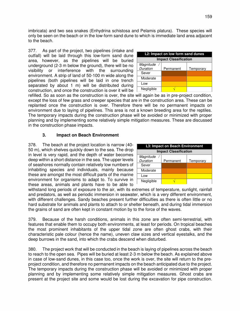
159
imbricata) and two sea snakes (Enhydrina schistosa and Pelamis platura). These species will only be seen on the beach or in the low-form sand dune to which is immediate land area adjacent to the beach. 377. As part of the project, two pipelines (intake and outfall) will be laid through this low-form sand dune area, however, as the pipelines will be buried underground (2-3 m below the ground), there will be no visibility or interference with the surrounding environment. A strip of land of 50-100 m wide along the pipelines (both pipelines will be laid in one trench separated by about 1 m) will be distributed during construction, and once the construction is over it will be refilled. So as soon as the construction is over, the site will again be as in pre-project condition, except the loss of few grass and creeper species that are in the construction area. These can be replanted once the construction is over. Therefore there will be no permanent impacts on environment due to laying of pipelines. This area is not a known breeding area for the reptiles. The temporary impacts during the construction phase will be avoided or minimized with proper planning and by implementing some relatively simple mitigation measures. These are discussed in the construction phase impacts.
3. Impact on Beach Environment
378. The beach at the project location is narrow (40-50 m), which shelves quickly down to the sea. The drop in level is very rapid, and the depth of water becomes deep within a short distance in the sea. The upper levels of seashores normally contain relatively low numbers of inhabiting species and individuals, mainly because these are amongst the most difficult parts of the marine environment for organisms to adapt to. To survive in these areas, animals and plants have to be able to withstand long periods of exposure to the air, with its extremes of temperature, sunlight, rainfall and predators, as well as periodic immersion in seawater, which is a very different environment, with different challenges. Sandy beaches present further difficulties as there is often little or no hard substrate for animals and plants to attach to or shelter beneath, and during tidal immersion the grains of sand are often kept in constant motion by to the force of the waves. 379. Because of the harsh conditions, animals in this zone are often semi-terrestrial, with features that enable them to occupy both environments, at least for periods. On tropical beaches the most prominent inhabitants of the upper tidal zone are often ghost crabs, with their characteristic pale colour (hence the name), uneven claw sizes and vertical eyestalks, and the deep burrows in the sand, into which the crabs descend when disturbed. 380. The project work that will be conducted in the beach is laying of pipelines across the beach to reach to the open sea. Pipes will be buried at least 2-3 m below the beach. As explained above in case of low-sand dunes, in this case too, once the work is over, the site will return to the pre-project condition, and therefore no permanent impacts on the beach anticipated due to the project. The temporary impacts during the construction phase will be avoided or minimized with proper planning and by implementing some relatively simple mitigation measures. Ghost crabs are present at the project site and some would be lost during the excavation for pipe construction.
L2: Impact on low form sand dunes
Impact Classification
Magnitude / Duration
Permanent
Temporary
Sever
Moderate
Low
Negligible √
L3: Impact on Beach Environment
Impact Classification
Magnitude / Duration
Permanent
Temporary
Sever
Moderate
Low
Negligible √
160
However these are very mobile animals, and many would scurry away from construction activity if it were done gradually. Ghost crabs are prominent and noticeable, but not rare or endangered, and the local population is quite dense, so their presence should not be a constraint on using the upper part of the beach as a construction area. Temporary impacts anticipated during construction are discussed in the construction phase impacts section in detail.
4. Impact on Marine Environment
381. Source of water for the RODP is the open sea, and to abstract water an intake pipeline will be laid 800 m into the sea including an intake structure at the mouth of intake to facilitate entry of water. The effluent (brine) generated from the RODP in desalination process will also be discharged into the sea via an outfall pipeline. This pipeline will be laid parallel to intake pipe (1 m apart) and up to 500 m inside the sea, the end of which will be fitted with 3 diffusers to allow for quick dispersion of brine. Both the pipelines will be buried minimum 500 mm under the sea bed. Intake structure will be partly buried under the sea bed and partly projected above the sea bed (2 m) to take water, and diffusers from the discharge end of the outfall will be also be projected above the sea bed (0.5-1 m) to allow proper dispersion. 382. The marine part of the project area, where intake and outfall pipelines and structures will be located, was studied quite extensively in the course of this project, through diving surveys of benthic epifauna, grab sampling of infauna, studies of phytoplankton and zooplankton captured by vertically-towed nets, and information on fish and fishing collected during the diving surveys, and from interviews with local fishermen’s representatives. The data from these various sources showed that, in contrast to other parts of the Jaffna peninsula where there is quite a wide variety of marine and coastal habitats and species, in this location the benthic environment is composed entirely of sand, and there is no rock, coral, sea grass or other different type of habitat. Sand is one of the least productive of marine habitats, and because of this and the lack of substrate diversity, this is quite a species-poor environment, where there are also low numbers of individuals, both on the seabed and in the water. 383. A total of just 22 benthic taxa were reported by the diving survey, comprising sponges, anemones, some coral, bivalve and gastropod molluscs, starfish, sea urchins and sea cucumbers. Most were typical epifauna (living on the seabed, not in the sediment) and only the starfish Luidia sp was recorded as being common, and only sand dollars were abundant. All other animals were present in very low numbers indeed and there were no macroscopic plants (seaweed), because there is no rock or other hard substrate to which they can attach. The grab survey found that the infauna comprised 26 species of polychaetes (segmented worms) 15 species of gastropod mollusc (snails), 12 species of bivalve (clams), 9 species of crustaceans (crabs, sandhoppers) and 2 echinoderms. The infauna is broadly similar to what has been found in other parts of Jaffna and elsewhere, and there is no evidence of anything unusual. 384. Intake and outfall pipeline construction will remove intertidal and subtidal sediment to create a trench, approximately 3 m wide (2 accommodate 2 pipes, 1 m apart) and 1.5-2 m deep 800 m long. This activity will disturb the benthic habitat in approximately 7,000 – 8,000 m2 area along the alignment of pipelines, including for placing of excavated material on the trench temporarily. Once the construction is over the trench will be refilled and as the pipelines are buried there will be no interference with the benthic habitat of the sea bed during the operation phase throughout the length of the pipelines. 385. None of the animals recorded in these surveys are rare or endangered according to the national or international red data lists, and even the two coral species are quite common in Sri

161
Lanka and elsewhere. It should also be noted that the hard coral Cycloseris cyclolites (mushroom coral) was present only as two dead pieces, the soft coral Dendronephthya sp was bleached and probably also dying, and several starfish were also seen to be damaged and dying. As per information gathered, the area may have been recently damaged by various type of fishing activities that are prevalent in this area (demersal fishing activities, Madel fishing activity and the murex fishery). Although none of the species are rare or endangered, four species (the hard and soft coral, tube anemone Cerianthus sp, and Gorgonians (sea whips or sea fans) are protected under the national Fauna and Flora Protection Ordinance (2009). According to IUCN Sri Lanka, the protection is intended to prevent these and other species being exploited commercially by the marine aquarium industry, supplying overseas markets. 386. This is clearly not a pristine, diverse and thriving benthic community, which is another reason why the ecological impacts can be accepted. Except for the four species protected under FFPO, 2009, there are no other species notable or endemic to this area, nor this is any unique habitat, including for those four species. Given the protection under the national regulation, the project may be considered to have significant impact if the protected species are disturbed or damaged by the project activity. It is, therefore, required to implement the following measures:
(i) Translocate the four protected species (the hard and soft coral, tube anemone, Cerianthus sp, and Gorgonians) that are present along the route of the intake and outfall to a safer place with similar benthic habitat.
(ii) Adopt non-discriminatory approach as far as possible to relocate all species in the area of concern irrespective of conservation status
(iii) Obtain permission from the Central Environment Authority (CEA) for translocation (iv) Translocation work to be conducted by a reputed and competent agency in the
field of wildlife conservation with previous marine translocation experience in Sri Lanka
(v) Translocation should be done immediately before the marine trenching work begins, and it should cover 50 m strip along the pipelines alignment and 50 m around intake and outfall
387. This matter has also been discussed with the CEA, and agreed that these species will be translocated to avoid damage. It was learnt that this kind of translocation is already conducted in a project in Sri Lanka with assistance of IUCN Sri Lanka. This work will also be delegated to IUCN, which has submitted a proposal for conducting this work, the cost of which is included in the environmental mitigation budget (proposal is attached at Appendix J). 388. The construction in the marine environment will however have certain negative impacts, though temporary. These are discussed in detail in the section on construction phase impacts. 388. While the pipes are buried under the sea bed, the intake structure with about 2 m diameter will project 2 m above the sea bed. Similarly, diffusers (3 No,s134 of 200 mm dia each placed at 5 m spacing) will be projected 0.5-1 m above the sea bed. Though these will be permanent structures on the sea bed, there are unlikely to be any impacts due to mere presence of these stationary structures, as they are small structures occupying a small area of the beach and that water column above the intake/diffuser is about 8-10 m, at which level there will be no notable
134 5 no’s for ultimate design capacity of 48,000 m3/day
L4: Impact on Marine Environment
Impact Classification
Magnitude / Duration
Permanent
Temporary
Sever
Moderate
Low
Negligible √
162
wildlife or plankton except benthic organisms. The risk of infringement, entrapment & entrainment of marines species in intake screen/structure is avoided/significantly minimized through various intake design measures. Similarly, potential impacts due to disposal of brine are also addressed through various design measures. 389. Following measures are already integrated into the design to avoid minimize impacts on marine life due to intake and outfall:
(i) Require that contactor to follow Best Technology Available for construction of intake
(ii) Minimizing size and projection of intake above the sea bed as far as possible (~2m dia & 2 m projection)
(iii) Providing a smooth surface structure that will not cause damage; ensure that there are no loosely hanging or suspended parts for the intake (round with a flat cap, and all smooth edges)
(iv) Structure is designed considering the changes in sea bottom profile, and to withstand against waves and currents and changing water depths
(v) The intake structure and outfall are to be marked with surface buoys and lights for night time detection
(vi) The outlet diffuser be installed so that the discharge ports are surrounded by rocks minimising the opportunity for fishermen’s net to become entangles
(vii) Locating intake significantly away from the shore (at least 800 m inside the sea), and where there is adequate depth of water column (~12 m);
(viii) Minimizing height of intake projection above the sea bottom (~2 m) (ix) Designing intake such that water from the sea is drawn from lower level of water
column but adequately above the sea bed to avoid entry of benthic organisms (~intake opening at 2m above sea bed)
(x) Design the open sea intake with appropriate velocity cap, which shall: o change the main direction of water withdrawal from vertical to horizontal135
(direction of water entry at the screens from open sea shall be horizontal) o provide minimum entry velocity of water at the intake screens from the open
sea to avoid aquatic species being sucking into the intake (maximum velocity of water at intake entry point (at screen) should not exceed 0.15 m/sec)
(xi) Provision of a coarse screen (<75 mm) at offshore intake tower and a fine screen (2 mm) at onshore intake pump station to minimize the entry of aquatic species.
(xii) Make necessary provision in the intake sectional area at the screen to ensure that maximum velocity limit remains throughout the project life by accommodating the growth of shellfish and blockage of screens by debris/infringement at least up to a cleaning cycle (by divers, for every 18-24 months)
(xiii) Design of outfall to achieve remarkable rates of dilution (salinity less than ambient +1 ppt) within 20-22 m radius, and achieving ambient level with 100 m radium from the point of port discharge
135 The advantages of velocity cap provision to an open intake include : (1) it eliminates vertical vortices and avoids
withdrawal from the more productive aquatic habitat which usually is located closer to the surface of the water body; and (2) it creates a horizontal velocity pattern which gives juvenile and adult fish an indication for danger – most fish have receptors along the length of their bodies that sense horizontal movement because in nature such movement is associated with unusual conditions. This natural indication combined with maintaining low through-screen velocity (0.15 m/s or less) provides fish in the area of the intake ample warning and opportunity to swim away from the intake.
163
5. Economic Activities: Fishing
390. As the project area, especially the intake and outfall are located in open sea, which is an active fishing area supporting livelihood of local fishermen, any change in the baseline condition may adversely impact the livelihoods of fishermen. The potential adverse impacts may be due to loss of fishing area due to location of project components, or interference with the surrounding fishing area by way of obstructing the movement boats or damaging fishing nets or affecting the fish productivity of the area. However, considering various design measures as suggested above in intake and outfall design, together with careful selection in no-fishing area, no significant adverse impacts on fishing activities are envisaged. These are discussed in detailed in operation phase impacts. C. Impacts due to Project Construction
1. Summary of the Construction Process
391. The RODP will comprise a series of individual elements shown in Table 9, most of which will be constructed at the on-land portion of the site. This includes: pre-treatment facilities; eight RO membrane trains; energy recovery pressure exchangers; post-treatment remineralisation (lime, CO2) and disinfection (calcium hypochlorite) systems; product water storage (10,000 m3 tank); and pump station. These will be housed in a variety of buildings, probably mainly of concrete, with metal sheeting for roofs and walls, and there may also be some more traditional brick and block structures. There will be an extensive ancillary infrastructure, including interconnecting pipework, electricity supplies, chemical storage tanks, and other facilities; and the site will also incorporate domestic water supply, drainage and sanitation systems, internal roads and other hard standing, fencing, lighting, landscaping, etc. The other plant components will be built into the adjacent seabed (intake tower and pipeline; outfall pipeline and diffuser array) and on the intervening land area (intake pump station and buried intake and outfall pipelines). The potable water conveyance pipeline will be buried along existing roads from RODP to Junction A9 on Jaffna – Kandy Road. 392. Construction is scheduled to begin in 2018 and should take around 2 years. The most likely approach is described in Section IV.G and is expected to include the following main activities, which will probably occur in approximately the order listed:
(i) Land clearance: removal of trees, shrubs and other vegetation from the site, by bulldozer and hand cutting, and transportation of debris on trucks for disposal;
(ii) Access roads to connect the site to existing B-class roads: will involve land clearance; removal of sand by bulldozer; application of aggregate from trucks; compaction by heavy roller; finishing with a bitumen/gravel topcoat. Existing roads may be widened via similar work at the edges, and repaired if needed;
(iii) Earthworks: bulldozers and backhoe / sling bucket excavators will clear loose surface sand from most of the site, which will be loaded into trucks and taken for disposal;
(iv) Excavation: backhoe / sling bucket excavators will dig trenches for pipes, cavities for building foundations, a deep void for pump station wet-well, etc. Drill attachments may be needed to cut through rock; material is loaded into dump trucks for disposal;
(v) Mechanical rock crusher: will operate throughout the early and mid-stages of construction, reclaiming re-usable sand, gravel and stone from excavated spoil;
(vi) Concrete plant: will operate in the mid-construction period, creating concrete for building foundations, the numerous RC structures on site, intake tower, etc.;

164
(vii) Spoil: unusable excavated material is taken by truck to approved disposal sites, including municipal dumpsite, any nearby construction areas needing infill, etc.;
(viii) Existing Quarries: will be used to source construction materials if available, and borrow pits may also be dug locally with agreement from landowners and client;
(ix) Concrete structures: steel reinforcing rods/bars are placed/attached by hand to form an interior skeleton of each structure; this is surrounded by metal/timber formwork to create a mould; ready-mix concrete is poured in and after setting, formwork is removed, and the concrete surface is finished by hand if required;
(x) Brick/block buildings and other structures: will be created mainly by hand, using standard house building techniques: bricklaying, plastering, carpentry, etc.;
(xi) Steel sheeting for walls, roofs, cladding, etc.: sheets are positioned by crane onto supporting steel girders or RC columns, and bolted into place by hand;
(xii) RODP components: will be mainly assembled on site from pre-fabricated proprietary elements, purchased from abroad, delivered to Colombo port/airport and transported to Jaffna on trucks. Site assembly will be facilitated by cranes;
(xiii) Other site infrastructure: water supply/drainage, roads, fencing, etc. are mostly built by small teams of labourers, assisted by backhoe / sling buckets for trenching, etc.;
(xiv) Beach construction area for pipe storage and pipeline assembly: crushed rock is tipped from trucks and spread/levelled by bulldozer, and seaward edges may be protected by larger stones; a concrete upper surface may also be added;
(xv) Intake/outfall pipes: trenches on land and in the seabed will be dug by backhoe / sling bucket (mounted on barges for marine work); lengths of HDPE pipe are welded together and floating buoys are attached; pipeline is fed out to sea on a barge, positioned over the trench and lowered by sequentially removing buoys, assisted by divers; the trench is then refilled with excavated sand by backhoe / sling bucket;
(xvi) Concrete intake tower: will probably be manufactured on land as a single pre-cast unit, lifted into place on the seabed by barge-mounted crane, and attached to the intake pipeline by underwater welding;
(xvii) Outfall “duckbill” diffuser will be constructed on land, floated into position pre-attached to the outfall pipeline, and buried in the trench as described above;
(xviii) Conveyance pipeline will buried along the existing roads (for 8km length); trench will be excavated with backhoe / sling bucket, pipes placed in the trench, jointed, tested and trenched refilled with excavated soil, and consolidated and road restored.
(xix) Photographs in Chapter IV show many of these activities conducted at construction sites elsewhere, and Photo 12 is a completed RODP in Australia.
393. The on-land portion of the site measures 200 x 200 m; and most construction activities will be conducted within this area, on an adjacent 500 x 50 m strip of coastal land (intake and outfall pipelines and intake pump house) and an area of seabed measuring approximately 800 x 5 m (intake and outfall structures and pipes), shown in Figure 1. Pipeline will be laid along the existing roads in about 1 m wide trench for 8 km length. Some facilities like the contractor’s offices and car parking may be located outside the site, and other offsite activities will include the access roads, quarries/borrow pits, spoil disposal, and transportation of materials, equipment and personnel. 394. From the above summary and the more detailed description and photographs in Chapter IV, it is clear that this is quite a complex project, which will involve specialised design of the plant and its individual components, and subsequent expert assembly, installation and testing of the
165
main technical elements. It is also clear that RODP construction will involve a number of different activities, concentrated in a relatively small area (4 ha in total), which will require very careful planning and implementation. Notwithstanding the complexity of the project, it is also apparent from the above summary, that the project will involve a great deal of basic construction work, which is common to most construction sites, albeit often at a smaller scale (land clearance, earthworks, excavation, sourcing of construction materials, disposal of spoil, and creation of concrete, brick and steel buildings). 395. A new transmission main pipeline of 800 mm diameter will be laid from RODP to the water delivery point on Jaffna-Kandy road (A9) that conveys treated water to Jaffna for supply to consumers. Pipeline for about 800 m crosses a lagoon (Vadamarachchi lagoon), at this portion, pipeline will be laid on simple concrete supports a spacing of 25-30 m. Supports will be constructed using less invasive techniques, either using precast blocks or cast in situ using simple processes. Most probably, precast pipes of diameter 0.5-1 m will be placed in the lagoon vertically by a crane placed on the road, and driven to a certain depth. Subsequently this will be filled with concrete to create a column. This process will be repeated till it reach the required height. This method will be less intrusive and there will be not be any notable effect on water quality.
2. Pre-construction Impacts and Mitigation Measures
396. Consents, permits, clearances, no objection certificates (NOCs). Project requires various clearances, permits etc., from government regulatory agencies. These include: EIA study & permission for implementation of project from Project Approving Agency (to be determined by CEA); Environmental Protection License; permits from Coastal Conservation Department, Marine Environment Protection Authority; etc., Failure to obtain necessary consents, permits, NOCs can result in design revisions, delay and/or stoppage of works. Project has already obtained approval from CEA (see Appendix B), and the remaining clearances needs to be obtained.
(i) Acknowledge in writing and provide report on compliance all obtained consents, permits, clearance, NOCs prior to start of construction.
(ii) Include in project implementation all conditions and provisions where necessary. 397. Construction activities could result in modification of species composition or benthic structure which can impact on the marine ecological communities. Potential impacts, e.g., major disturbance, can also arise if work activities and access are not managed effectively. 398. Mitigation measures. In general, the aim is to ensure that there is no significant disturbance / impact on marine habitat resulting from any of the work within sea or on the beach. The contractor will be required to:
(i) Designate a full time environment specialist (expertize in works in marine habitats) who will be in charge of coordination with PMU for updating this draft EIA and developing EMP as per detailed design. and implementing EMP including conduct of all surveys, monitoring actions etc.,.
(ii) Environmental specialist shall be in place from the day of mobilization of DBO contractor (throughout design and construction, and intermittent during operation phase)
(iii) Coordinate with the PCMIU on confirmatory surveys to be conducted during the design phase and complete as required with support of external experts
399. Tree cutting. Proposed RODP site and new approach road alignment is a coastal scrub land covered with shrubs and few trees – mostly of Palmyra palms. Although the area around project has presence of few protected flora species as presented in the baseline profile section,
166
none of these are noticed within the demarcated land of RODP and approach roads. Trees and shrubs located in the approach road alignment will also need to be completely removed to create a road. For RODP, trees will be retained within the plant site where there will be no construction as per the technical feasibility to be decided during the detailed design phase. Following measures need to be implemented to minimize / compensate for the loss of tree cover.
(i) Conduct survey and confirm that there are no protected species within the designated land for RODP, and approach roads and pipeline alignment
(ii) If there are any protected species, avoid distributing/removing the protected/rare species; they shall be absorbed into the layout design where feasible; or translocate these prior to start of construction
(iii) Minimize overall removal of all trees by adopting to site condition and with appropriate layout design
(iv) Obtain prior permission for tree cutting (v) Plant and at least 2 trees for each tree that is removed
400. Disturbance to Natural drainage. The natural ground in the RODP land is slightly undulating with sand dunes thickly covered with shrubs. Natural drainage is not clearly defined on ground, however, a drainage line (channel) visible at the site that runs across the site from upper areas and towards the coast. Any disturbance to natural drainage will have negative impacts, like flooding, and to avoid this the following measures need to be implemented:
(i) Identify and confirm drainage lines on the RODP site topographic survey map during the detailed design
(ii) Integrate these channels in the layout design so that water flow is uninterrupted during the rains, and ensure proper capacity channels as per the run off design
(iii) Provide cross drainage structures wherever necessary along the new approach roads so that natural drainage flow is not disturbed
401. Utilities. Except the potable water conveyance pipeline which will be laid along the public roads from RODP to Puthukkadu junction on Jaffna – Kandy Road, all components are located in places where there are no existing utilities. The site for RODP is unused scrub land with no utilities, and the strip of land that will be used for laying of intake and outfall pipelines from RODP to into sea is also unused at present. 402. The most noticeable effect will be the potential interruption of services and utilities to residents and businesses in the project area along which the conveyance pipeline is laid. These interruptions will be scheduled and intermittently related to localized construction activities. Telephone lines, electric poles and wires, water and sewer lines within road ROWs may be damaged if these are falling in the alignment of the transmission mains. The intake and outfall pipeline will cross the road (Mamune Road), which is parallel to beach. There are no utilities on the beach that will be affected by the work. 403. To mitigate the adverse impacts due to relocation of the utilities, the contractor will:
(i) Identify and include locations and operators of these utilities in the detailed design documents to prevent unnecessary disruption of services during the construction phase.
(ii) Prepare a contingency plan to include actions to be done in case of unintentional interruption of services.
(iii) Identify the list of affected utilities and operators and coordinate closely with relevant government departments.
(iv) If relocations are necessary, coordinate with the providers to relocate the utility.

167
404. Sites for construction work camps and areas for stockpile, storage and disposal. The priority is to locate these near the project area. The contractor will be required to meet the following criteria for the sites:
(i) Except disposal sites, all the work sites (camps, storage, stockpiles etc.) will be located within the selected RODP site.
(ii) No camp or store (even if temporary) shall be located on the beach, from sea to up to Mamune road
(iii) For conveyance pipeline works, material shall be brought from RODP site as and when required, and temporary storage of material (pipe, sand etc.,) can be made near the work site along the road itself within the RoW.
(iv) No temporary storage shall be located at Vadamarachchi lagoon section 405. Sources of construction materials. Significant amounts of gravel, sand, and aggregate will be required for this project, although no estimates are made at this stage.136 For this project, the general lack of suitable building materials on the Jaffna Peninsula means that sand and stone will probably be obtained from quarries on the mainland. Quarries inevitably cause extensive physical changes, because their purose is to provide natural materials for construction and other purposes, which are excavated from the ground, leaving large cavities, or levelling hillsides, etc. Extraction of materials can disrupt natural land contours and vegetation resulting in accelerated erosion, disturbance in natural drainage patterns, ponding and water logging, and water pollution. The physical damage caused by quarries is controlled by allowing them to operate within specific limited areas only, so the damage is restricted in extent and not allowed to spread indiscriminately. Ideally quarries are located in uninhabited areas to avoid exposing residents to dust and noise and other related impacts; and new quarries are subject to a rigorous process of environmental assessment to ensure appropriate siting and adequate environmental controls on the operation. The contractor will be required to:
(i) Obtain construction materials for this project from the existing quarries permitted / licensed by government (Geological Survey and Mines Bureau, GSMB) only; this will ensure that proper controls are in place
(ii) If the contractor proposes to obtain materials from any other sources, e.g. new borrow-pits, prior permission must be obtained from the PMU, landowner, GSMB, and the Central Environment Authority, and the environmental impacts of the operation should properly examined and mitigated as necessary.
(iii) Verify suitability of all material sources and obtain approval from PMU (iv) Make efforts to minimize the overall material requirement for the project by
adopting various approaches – balanced cut and fill, re-use as much excavated material from this project as possible
(v) Submit to PMU on a monthly basis documentation of sources of materials with quantities.
406. Access. Hauling of construction materials and operation of equipment on-site can cause traffic problems and conflicts in ROWs along alignments of transmission mains. The amount of construction truck traffic will be substantial due to the amount of work. Construction traffic will access most work areas from the existing roads/highway therefore potential impacts will be of short-duration, localized and can be mitigated. The contractor will need to adopt the following mitigation measures:
(i) Plan transportation routes so that heavy vehicles do not use narrow local roads, except in the immediate vicinity of delivery sites.
(ii) Schedule transport and hauling activities during non-peak hours.
136 This will be updated by the contractor during the detailed design, which will be verified by PMC and PMU.
168
(iii) Locate entry and exit points in areas where there is low potential for traffic congestion.
(iv) Keep the site free from all unnecessary obstructions. (v) Drive vehicles in a considerate manner. (vi) Coordinate with the Traffic Police for temporary road diversions and for provision
of traffic aids if transportation activities cannot be avoided during peak hours. (vii) Notify affected sensitive receptors by providing sign boards with information about
the nature and duration of construction works and contact numbers for concerns/complaints.
(viii) Ensure access to households along the alignment of conveyance main during the construction phase.
407. Access disruption to fishing community & Impact on surrounding Fishing Activity. The beach is used by local fishermen for fishing activities – launching, exiting fishing boats etc., Although the work on the beach will be confined only to a narrow strip of land, due to excavation for trenches and movement of equipment across the beach to access sea, this work may obstruct the movement of fishermen, especially from Thalaiyadi village into sea, if activities are not properly planned. There is no likelihood of marine construction distributing the fishing activity directly, as there is no fishing activity within the construction area. However, the disturbance related to work such as noise, sediment plumes, movement of workmen and machinery can potentially affect surrounding fishing activity by reducing the fish catch if the disturbance is not controlled within the immediate surroundings of 500 m. To mitigate/minimize the adverse impacts, the contractor will:
(i) Prepare a Method Statement for marine works; consider less disturbing methods, and including the following: - Plan all beach works such that there is no or minimal disturbance to
movement of fishermen, boat landing sites etc.; - demarcate the work area, and if there any existing lines of movement within
that beach front, ensure alternative approach is available; coordinate with PMU to consult with local community to plan works
- Limit the size of the construction area on the beach and there shall be no encroachment to outside the specified areas;
- Access should not be closed completely, provide alternative way for fishermen to approach to their work places (e.g. boat landing sites); leave mounds of soil in between or provide wooden planks or metal sheets with proper barricading to allow temporary access
- limit the spread of suspended sediment by conducting marine trenching works in calmer dry season conditions, and stopping work if the spread of sediment in the water becomes excessive as per the guideline below
- The turbidity of the water is to be measured (ISO 7027) at the edge of the construction zone137 during trenching and backfilling activities; when the turbidity exceeds the minimum of the background turbidity plus 20% or 100 NTU, the trenching is to cease until the turbidity returns to the background level plus 10%.
- Construction noise to comply with International Finance Corporation (IFC) Environmental Health and Safety (EHS) Guidelines Table 1.7.1 and these will be monitored for compliance with these guidelines
137 The construction zone has been set as follows: A construction exclusion zone marked by buoys must be established
during the Design-Build period for these works. The zone must clear all works by 50 meters.

169
- It will also be important for the contractor to enforce high standards of behavior amongst the workforce both on and off site, and to maintain clean, tidy and highly professional worksites, to ensure that all persons who come into contact with the construction gain a positive impression of the conduct of the project.
(ii) If there is any disruption to fishing activity, compensation to be provided as per the resettlement plan of the project
3. Construction Impacts & Mitigation Measures: Terrestrial construction
408. Site preparation, Excavation. All of the main construction activities will affect the physical environment, and some of the most profound changes at the on-land part of the site will occur at the very beginning, when the site is cleared of vegetation and probably also the surface covering of loose sand, to expose the firmer limestone and gravel substrate below, into which the building foundations and other structures will be embedded. The area between the site and the beach will not require extensive preparation because there is a lot less vegetation (Photos 1 and 3) and the surface sand will only need to be removed from the relatively small strip of land to lay intake and outfall pipelines area in which the intake pump station and wet-well are to be built. This will change the physical character of the area, from the present landscape of low coastal dunes with scrub vegetation shown in Photos 2. This in itself will not be a major negative impact, given that there are no residents in the immediate vicinity to notice the different landscape, and the area has no special function that could be affected by this change. Impacts due to change of scrub land to project has been already discussed in location impacts. There are no notable vegetation along the roads where conveyance pipe will be laid, and therefore requires no significant site preparation. 409. Construction of buildings will probably begin once the first foundations have been excavated, and it will then continue in stages across the site, throughout much of the middle part of the construction period. Concreting will be the main activity, as most buildings will be constructed of this material, and even if brick, block and steel structures are also used, they will have foundations of concrete and possibly also structural columns. Areas of hard standing outside could be of concrete, as will the plinths and other structures upon which the various RODP components are mounted and affixed. So the production, delivery and application of concrete is a major element of the construction project. 410. RODP components and site infrastructure. Installation of the numerous, mainly pre-fabricated elements to create each of the individual RODP components is an extremely complex task, which will require a great deal of planning and very careful implementation, over a period of several months, possibly longer. Acquisition and delivery of all of the component parts alone will be an enormous task, even before the units are checked, coordinated, installed, connected up and tested. Despite the complexity of the process, this is not part of the project that will have major physical impacts, mainly because most of the components will be assembled inside completed buildings, so the physical changes will be mainly localised and only noticeable from within. Here again the main physical risks are of injury to the workers and staff who are involved in the work, and these are discussed below. Installation of the other site infrastructure will include both operational elements like large pipelines connecting the RODP components, electricity supplies, controlling switchgear and the like, as well as generally smaller service infrastructure such as internal plumbing and wiring, exterior lighting, signage, site roads, etc. 411. Conveyance Pipeline works. Once the trench is excavated for pipelines, the pipes (brought to site on trucks and stored on unused land nearby) will be placed in the trench by hand

170
or using a small rig. Pipes will be joined by hand, after which sand from local quarries will be shovelled into the trench beneath and around the pipe for support and protection. Soil will then be replaced manually on top of the pipe and compacted by a vibrating compressor. and the appropriate surface will be reapplied on completion. Pipe supports across the lagoon will be constructed via precast blocks and using cranes. 412. Elements of the construction process to be conducted offsite include access roads, quarries or borrow pits, and disposal of spoil. These are all activities that cause changes in the physical environment, and as these will occur away from the main site, it will be important that the work is done sensitively and that physical changes are minimised to the extent possible. Access roads, and any improvement and widening of the existing B-class roads will be designed in order to provide safe, reliable and convenient access to the plant, whilst maintaining the safety of other road users and the public at large. Road widths, camber, materials and infrastructure (kerbs, drains, etc.), will be designed with these as key factors, along with cost considerations. Much of the land around the site is owned by the government and is not occupied or used for any economic purpose, and the access roads will be located on these areas. Given the unoccupied nature of the land, construction activities might tend to spread over a larger area than necessary, because of the lack of physical restraints. This would cause unnecessary physical and ecological damage to these areas so the contractor should ensure that construction work is done within standard working widths, and that the sites are accessed over existing tracks, rather than driving over undamaged areas. Designs for new roads and improvements to existing roads should include effective drainage, to solve some of the current localised flooding noted by the community and to avoid causing new problems. 413. Impacts on Physical Environment: Air Quality. Handling potentially large quantity of sand during site clearance carries the risk of producing significant amounts of airborne dust. Given dry and windy conditions significant dust will be generated if proper precautions are not taken. Site excavation to create foundations for buildings, trenches for infrastructure, and other cavities, will also create dust. Dust generation will be significant if land clearance and earthworks will be conducted as over the whole project site at the same time. Airborne dust could cause respiratory problems if people inhale the particulate matter It can also reduce the productivity of terrestrial and aquatic plants by coating the surfaces of leaves, and reducing the penetration of light into the sea. These are not ecologically sensitive environments, so reductions in photosynthesis should not be problematic, and with the nearest inhabitation 750 m away, there should also not be significant risks to the health of local residents. There could however be serious risks to the health of workers and staff present on site at this time, and especially those involved in the land clearance and earthworks operations. It would also not improve public perception of the project if large dust clouds were visible locally; so the contractor should take following actions to minimise dust production:
(i) As far as possible, plan site clearance and earthwork activities towards the end of the north-east monsoon (January - February), when the soils will be damp naturally, without being subject to the downpours of the previous two months.
(ii) To suppress dust, Contractor should water exposed sand, soil and stockpiled material on site sufficiently frequently (several times per day)
(iii) Provide a compound wall or wind breaking wall/structure around the plant site to minimize the wind; this will minimize the dust generation, and also drifting of sand into excavated trenches
(iv) If dust generation is significant, provide a dust screen of appropriate height duly considering the wind directions
(v) Workers and staff should be provided with dust masks and instructed to use them when on site
171
(vi) Conduct work in stages to reduce dust impacts; clearing and then conducting construction in only a portion of the site at a time.
(vii) Retention of vegetation is the most natural and effective way of protecting soil from erosion by wind and rain; the feasibility of phasing site clearance in this way in order to reduce these impacts should be investigated when the construction work is planned in detail by the DBO Contractor.
(viii) Contractor’s environmental manager should monitor these activities and take action to apply the mitigation if dust production becomes significant.
(ix) Apply water prior to leveling or any other earth moving activity to keep the soil moist throughout the process
(x) Control access to work area, prevent unnecessary movement of vehicles, workers, public trespassing into work areas; limiting soil disturbance will minimize dust generation
414. Material and waste/debris transport, and works along the public roads carrying, have high potential to generate dust. Also emissions from construction vehicles, equipment, and machinery used for excavation and construction will induce impacts on the air quality. Anticipated impacts include dust and increase in concentration of vehicle-related pollutants such as carbon monoxide, sulphur oxides, particulate matter, nitrous oxides, and hydrocarbons. Dust generation will be significant during pipeline laying along the roads. To mitigate the impacts, construction contractors will be required to:
(i) Use tarpaulins to cover the loose material (soil, sand, aggregate etc.,) when transported by trucks;
(ii) Clean wheels and undercarriage of haul trucks prior to leaving construction site/quarry
(iii) Control dust generation while unloading the loose material (particularly aggregate, soil) at the site by sprinkling water and unloading inside the barricaded area
(iv) Stabilize surface soils where loaders, support equipment and vehicles will operate by using water and maintain surface soils in a stabilized condition Vehicular pollution
(i) Ensure that all the construction equipment, machinery are fitted with pollution control devises, which are operating correctly,
(ii) Ensure that only those vehicles and equipment in good condition, and are in good maintenance are used for project construction
(iii) Vehicles / equipment should have a valid Vehicle Emission Certificate (VEC) showcasing emissions below the specified limits
(iv) Maintain VEC records of all vehicles all times for ready inspection at the work sites
415. Impacts on Physical Environment: Generation of Soil, Wastes & Debris. Solid wastes generated from the construction activities are vegetation cleared from the site, excess excavated earth (spoils), discarded construction materials, cement bags, wood, steel, oils, fuels and other similar items. Domestic solid wastes may also be generated from the workers’ camp. Improper waste management could cause odour and vermin problems, pollution and flow obstruction of nearby watercourses and could negatively impact the landscape. Vegetation will probably be cleared by bulldozer and by hand cutting; and the sand layer will be removed by bulldozer and backhoe / sling bucket, with waste material from both sources loaded into dump trucks for transport to offsite disposal. The amount of material has not been calculated, but a crude estimate can be made by assuming say a 2 m high canopy of shrubs and small trees covering 75% of the on-land site, and an average depth of sand of say 0.5 m. In a 200 x 200 m area, this would

172
produce 35,000 m3 of waste vegetation (plus an additional 10% or more from the roots, i.e. a total of around 40,000 m3) and 15,000 m3 of waste sand. For conveyance pipeline, a trench of 1 m wide and 2 m deep will be excavated adjacent to the existing roads, in the un-used area within the ROW, at the edge of the tarmac. Trenches will be dug using a backhoe / sling bucket digger. Trench construction will excavate 16,000 m3 of soil. After construction, approximately 25% of the trench will be occupied by the pipe, 25% by fresh sand, and the remaining 50% by refilling of excavated soil. This means that around 4,000 m3 of sand will be brought to site, 4,000 m3 of excavated soil will be retained for replacement in the trench, and 8,000 m3 of waste material will be left over. 416. These are large quantities, which could affect land, property, crops and inhabitants. There will be quite large physical changes at the construction sites, and this quantity of waste could not be dumped without causing further physical impacts (on air quality, topography, soil quality, etc.) at the point of disposal. Action will therefore be needed to reduce physical impacts at both the construction and disposal sites, by reducing the amount of material to be dumped. The contractor should therefore make serious efforts to reduce the amount of waste that is simply discarded, by:
(i) Prepare and implement a Construction Waste Management Plan (CWMP); include the following measures in the plan
(ii) Reuse as much waste sand in this project as possible; (iii) Find alternative beneficial uses for any unused sand, for example as infill in other
construction works; (iv) stripping out the trunks and larger branches from trees and shrubs and providing
these to the local community free of charge for building or fuel. (v) No vegetation should be burnt on site to avoid release of greenhouse gases; (vi) All waste/waste sand and vegetation should be covered by secure tarpaulins
whenever transported offsite, to prevent material being blown from trucks (vii) Avoid stockpiling any excess spoils at the site for long time. Excess excavated
soils should be disposed off to approved designated areas immediately (viii) If disposal is required, the site shall be selected from barren, infertile lands,
no/least vegetated areas; site should located away from residential areas, forests, coast, water bodies and any other sensitive land uses
(ix) Domestic solid wastes should be properly segregated in biodegradable and non-biodegradable for collection and disposal to designated solid waste disposal site; create a compost pit at workers camp sites for disposal of biodegradable waste; non-biodegradable / recyclable material shall be collected separately and sold in the local recycling material market
(x) Residual and hazardous wastes such as oils, fuels, and lubricants shall be disposed off in disposal sites/third party sources approved by CEA;
(xi) Prohibit burning of construction and/or domestic waste; (xii) Ensure that wastes are not haphazardly thrown in and around the project site;
provide proper collection bins, and create awareness to use the dust bins. (xiii) Conduct site clearance and restoration to original condition after the completion of
construction work especially along the conveyance pipeline route, beach area, and around the RODP; PMU to ensure that site is properly restored prior to issuing of construction completion certificate
417. Impacts on Physical Environment: Surface & Groundwater Water Quality. Run-off from stockpiled materials and chemicals from fuels and lubricants during construction works can contaminate downstream surface water quality of the lagoons, and sea. Although confined to two monsoon seasons, the project area receives good rainfall. Construction contractor will be required to:
173
(i) Avoid earthworks during monsoon season to prevent the problem of soil run-off (ii) Avoid stockpiling of earth fill especially during the monsoon season unless covered
by tarpaulins or plastic sheets; (iii) Prioritize re-use of excess spoils and materials in the construction works. If spoils
will be disposed, only designated disposal areas shall be used; (iv) Install temporary silt traps or sedimentation basins along the drainage leading to
the water bodies; (v) Place storage areas for fuels and lubricants away from any drainage leading to
water bodies; (vi) Store fuel, construction chemicals etc., on an impervious floor, also avoid spillage
by careful handling (vii) Dispose any wastes generated by construction activities in designated sites; and (viii) Conduct surface quality inspection according to the Environmental Management
Plan (EMP). 418. Degradation of Vadamarachchi Lagoon Water Quality. During construction of concrete supports in the lagoon to place the conveyance pipeline on them to cross the lagoon, there is potential for increase in suspended solids and turbidity in the lagoon in the surroundings of construction site. It is proposed construct the support using less invasive and less disturbing construction techniques. In Sri Lanka, with numerous inland water bodies, laying pipelines over water bodies to cross over is very common. Construction method involves lowering a precast pipe (of diameter ~ 1m) into the lagoon at identified support location, and pushing down the precast pipe to required depth in the l bed to reach relatively hard bed. Precast pipe serves as casing, in which reinforcement rods are lowered and concrete is poured to build the pipe support, and there will be no requirement to remove the casing, which will avoid disturbance to water body. As concreting is done inside the pipe, it prevents wet or curing concrete entering the lagoon. Sand, silt and water displaced and collected during the lowering of pipe and concreting pouring will be pumped out. Other impacts will be related to spillage of concrete in the lagoon during the pouring. Several types of construction equipment and vehicles, such as concrete trucks, and cranes, pumps will be used in construction. Fuel and oil from this equipment may be spilled or leak to river. To mitigate / minimize the impact, the contractor will be required to:
(i) Contractor to prepare a method statement following internationally accepted construction procedures in wetlands. This inter alia include pollution control (water, air, noise), limiting disturbance, unharming wildlife etc.,
(ii) Schedule works during low water level in the lagoon; no works be scheduled during September to March (migratory season for birds)
(iii) Lower the precast pipe slowly to allow any aquatic organism at the place to move away, and avoid any significant disturbance to the still water
(iv) Water, slurry (silt / sand mixed with water) collected in the lowered pipe shall not be pumped/disposed back directly into the lagoon which will degrade the water quality, increase the silt load; this should be pumped to a temporary sedimentation basin or tank; after proper settling in the basin, clarified water can be let into lagoon by gravity (not to be pumped directly into the lagoon, which will disturb the water); collected sand and silt be utilized in the construction and shall not be disposed off in the lagoon
(v) Dispose any residuals at identified disposal site (vi) Dispose waste oil and lubricants generated as per prevailing provisions (vii) Stock pile construction material away from the lagoon area (viii) Develop a concrete spill prevention and containment plan as part of the EMP,
educate workers about the plan, and have the necessary materials on site prior to and during construction.

174
(ix) Ensure that no equipment/material /workers, except the precast pipe that is lowered into water, comes in contact with water; this should strictly be prevented
(x) Do not conduct any cleaning, washing, rinsing of concrete or other equipment near the lagoon; prevent any waste / water from discharging into the lagoon.
(xi) Refuel equipment within the designated refueling containment area away from the lagoon
(xii) Inspect all vehicles daily for fluid leaks before leaving the vehicle staging area, and repair any leaks before the vehicle resumes operation.
(xiii) Ensure that no silt laden runoff from nearby construction area (pipeline construction sites) enter the lagoon; this can be avoided by scheduling the construction work around the lagoon area in non-monsoon; to accommodate for untimely rains, contractor should provide silt traps as required
(xiv) Excess water sprinkling on soil, material to control dust may also generate runoff which may enter the lagoon; this should be avoided by controlled water sprinkling
419. Another physical impact that is often associated with excavation is the effect on drainage and the local water table if groundwater and surface water collect in the voids. As the project area located close the coast, the water may be collected in the deep foundation pits / and trenches as they are excavated. The water so collected in excavated pits will contain silt and disposal of this in drainage channels leads to silting, and degrading the water quality of receiving water body. To avoid this the contractor needs to be implement the following measures:
(i) Pump out the water collected in the pits / excavations to a temporary sedimentation pond; dispose off only clarified water into drainage channels/streams after sedimentation in the temporary ponds
(ii) Consider safety aspects related to trench /pit collapse due to accumulation of water 420. Impacts on Physical Environment: due to Concrete Batching Plant operation Huge quantities of cement concrete will be required for construction, and therefore it is most likely that contractor will installed a batching plant to produce the concrete on site. This will have a major role throughout the building construction period, and will be subject to heavy and regular usage. The main environmental risks associated with this activity relate to the spillage of chemicals used in concrete mixes and stored on site, and the wash-out of these chemicals from mixer trucks or from leaks and spillages during concrete application. An operation of this scale is really only achievable by a large and modern concreting plant; and such plants are equipped with an array of electronic equipment, designed to provide highly accurate mixes, and to greatly reduce the risks of spillage that are associated with older less automated systems. In such circumstances the main mitigation needed will be to ensure the plant and mixer trucks are operated properly. Dust generation is anticipated from aggregate, sand and cement loading operations. The contractor should therefore take action to ensure the following:
(i) Ensure that batching plant is installed with in-built air pollution and dust control system; for fugitive emissions /dust from loading area, provide dust screen around the components
(ii) The concreting plant is operated and maintained at all times according to O&M manuals provided by the equipment manufacturer;
(iii) The concrete loading area is equipped with a leak-proof concrete floor, from which all drainage is collected and treated as necessary prior to discharge;
(iv) Mixer trucks and especially mixer drums are washed out only in a designated area, which should also be equipped with a leak-proof floor, from which drainage is collected and treated as necessary;
(v) All chemicals used in concrete preparation are properly stored, whether dry, in powder or granular form, or as liquids. Storage facilities should be as specified in

175
the appropriate international standard, and should include equipment to extract dust and completely contain any spillage from leaks.
421. Impacts on Physical Environment: Noise and Vibration. RODP construction site is located away from habitation (750 m), and there are no sensitive features in the site. It is unlikely that noise from the RODP site would disturb local residents, although this should also be checked during the construction period so that action can be taken if necessary. Scrub land around site is also home to several local birds however, due to the construction activity and disturbance, birds will choose other the scrub lands away from the plant site, which are spread over vast area in the coastal belt around the site. Vadamarachchi lagoon, along which conveyance pipeline is home for various birds also attracts migratory birds, although it is not a known or important bird area. Nevertheless, some migratory bird visit the lagoon are in the period between September to March. This lagoon is quite far away from the RODP plant (1-2 km), however, the potable water conveyance pipeline will be laid through the lagoon area along an existing road. At the lagoon section, pipes will be laid on concrete supports in the lagoon area. No high noise generating activities like piling are envisaged. However, construction activities will generate certain noise, which will disturb the local environment, though temporarily. Increase in noise level may be caused by excavation, particularly breaking of cement concrete or bitumen roads for laying of pumping main, operation of construction equipment like batching plant, fabrication and arrangement of steel / metal components, and the transportation of equipment, materials, and people. Vibration generated from construction activity, for instance from the use of pneumatic drills, will have impact on nearby buildings. 422. Greatest noise from the proposed work is expected from fabrication of steel and metal components. Other noise sources will include standard construction equipment such as dump trucks, backhoe / sling buckets, graders, pavers, and other machinery. The levels in Table 34 can be expected only when the equipment is within 50 feet of the receiver. All buildings bordering on the intake wells area can expect maximum construction noise levels in the 80 to 90 dB(A) range when equipment is operating immediately next to them. These noise levels will decrease as the construction operations move farther away.
Table 34: Typical Noise Levels (in dB) of Principal Construction Equipment
CLEARING STRUCTURE CONSTRUCTION
Bulldozer 80 Crane 75-77 Front end loader 72-84 Welding generator 71-82 Jack hammer 81-98 Concrete mixer 74-88 Crane with ball 75-87 Concrete pump 81-84 Concrete vibrator 76 EXCAVATION & EARTH MOVING Air compressor 74-87 Bulldozer 80 Pneumatic tools 81-98 Backhoe / sling bucket 72-93 Bulldozer 80 Front end loader 72-84 Cement and dump trucks 83-94 Dump truck 83-94 Front end loader 72-84 Jack hammer 81-98 Dump truck 83-94 Scraper 80-93 Paver 86-88 GRADING AND COMPACTING LANDSCAPING AND CLEAN-UP Grader 80-93 Bulldozer 80 Roller 73-75 Backhoe / sling bucket 72-93 Truck 83-94 PAVING Front end loader 72-84 Paver 86-88 Dump truck 83-94 Truck 83-94 Paver 86-88 Tamper 74-77 Dump truck 83-94
176
Source: U.S. Environmental Protection Agency. Noise from Construction Equipment and Operations. Building Equipment and Home Appliances. NJID. 300.1. December 31. 1971 423. Noise impact is negative but short-term, and reversible by mitigation measures. The construction contractor will be required to:
(i) Do not conduct activities (pipe laying) in and around lagoon area (lagoon section + 0.5 km on both the sides) during September to March period; conduct of works at this stretch may be immediately planned to complete during the following intermonsoon season.
(ii) Limit construction activities to day time only (iii) Noise level at the boundary of plant site shall not exceed 70 dB(A) during day and
45 dB(A) during night (iv) Noise level at the lagoon shall not exceed 60 dB(A) during day time; and no work
shall be conducted at night time (v) Conduct regular monitoring of noise levels as per EMP (vi) Minimize noise from construction equipment by using vehicle silencers, fitting
jackhammers with noise-reducing mufflers, and use portable street barriers to minimize sound impact to surrounding sensitive receptor; and
(vii) Avoid loud random noise from sirens, air compression, etc. (viii) Avoid using multiple high noise generating equipment / activities simultaneously (ix) Install temporary or portable acoustic barriers around stationary construction noise
sources (x) Identify any buildings at risk from vibration damage and avoiding any use of
pneumatic drills or heavy vehicles in the vicinity (for pipeline works) (xi) Horns should not be used unless it is necessary to warn other road users or
animals of the vehicle’s approach; (xii) Consult local communities in advance of the work to identify and address key
issues, and avoid working at sensitive times, such as religious and cultural festivals (for pipeline works)
424. Operation of construction equipment causes ground vibrations which flow through the ground, and the strength is diminished with the distance. Structures / building located on the surrounding soil will absorb these vibrations, resulting in changes varying from not noticeable to heavy damages if the vibration is very high. The impact of vibration will also depend on the stability of the nearby structure as weak, old or fragile structures may experience greatest impacts. Vibration is not an issue in the proposed project construction, as there are no structures located in the vicinity. 425. Impacts on Biological Environment - Flora and Fauna. In terms of terrestrial ecology, the main impacts will occur at the very beginning of the construction period, when vegetation is cleared from the site. This will remove and kill all of the scrub vegetation that is currently present; and it will also kill at least some of the inhabiting animals, especially if bulldozers or excavators are used in the clearance operation as there is then a greater possibility of animals being crushed, or buried and smothered in the sand. It was estimated above that the volume of vegetation removed could be as much as 50,000 m3, which is a relatively large biomass. As far as animals are concerned, their motility will allow many to escape, in particular the birds, insects and mammals; but some will inevitably be killed, and even those that do move from the area may be unable to establish themselves in the surrounding habitat, and may be exposed to predators during their forced migration. Although the loss of plants and animals is not desirable, it cannot be considered as significant in ecological terms. It is a typical type of coastal scrub land habitat that is present in the dry-zone coastal and marine belt throughout Sri Lanka, and is found along

177
most of the north-eastern Jaffna coastline, between Point Pedro and Mullaittivu on the mainland. The faunal species were again those that would be expected in coastal areas, and the avifauna included a number of waders and other water birds, which would be feeding on the adjacent beach and shallows, and roosting and breeding in the adjacent scrublands. In general the fauna is also quite typical of the species that are known to inhabit the coastal scrublands of Sri Lanka, and as indicated above, the fauna would undoubtedly be less affected by site clearance than the flora, as many animals would move away from the area once the noise and disturbance of the operation became apparent and re-establish themselves in adjacent areas. As required by accepted best practice, the contractor should take steps to ensure that ecological losses are limited to only those that are strictly required in order to provide the project. There is also potential for workers to catch animals (fishes, turtles, birds, etc.) and/or kill other terrestrial and aquatic life in the nearby scrub land. Following measures needs to be implemented:
(i) Ensure that there is no loss of plants or animals outside the designated footprint of construction areas, and no excessive dust/emissions/noise from those areas that would harm wildlife in adjacent areas.
(ii) Provide training to all site staff and workers to explain the importance of the animals and plants on site and in the surrounding area, and their vulnerability;
(iii) Prohibit any deliberate killing or harming of animals on or off-site, any damage of vegetation outside of the designated construction areas, and any hunting or fishing at the site or in nearby areas by site personnel; preventive actions shall be put in place by contractor for hunting/killing wild animals
(iv) Ensure that all site-related activity is conducted strictly within the site footprint (including offices, car parking and other activities that might normally be located in an exterior contractor’s area);
(v) Ensure that all construction work or other activities near the site perimeter are conducted with particular care and include measures to reduce production of noise and dust to the minimum possible;
(vi) Conduct the site clearance and earthworks in a phased manner, gradually advancing noise and visual disturbance, which will encourage animals to leave before their habitat is affected.
(vii) To protect site personnel, training should also be provided to enable them to recognize and deal safely and humanely will all venomous animals that may be encountered (e.g. snakes and scorpions).
(viii) Conduct site preparation activities, including vegetation removals, outside of the breeding season for wildlife, including migratory birds.
(ix) Prevent access to areas located beyond the construction zone. (x) Limit activities within the work area. (xi) Provide to workers or post in public places for the workers, illustrations or pictures
of protected, endangered, threatened, and/or near-threatened species, which can be found in the work area or its immediate surroundings.
(xii) Instruct workers to stop work immediately and report to supervisor/contractor’s environment specialist any work/activity any on-site presence of protected, endangered, threatened, and/or near-threatened species.
(xiii) To minimize/ mitigate impacts due to removal of vegetation / trees, implement measures suggested in Section VI.B.1 (pre-construction impacts)
426. Impacts on protected species of flora and fauna. Of the eight protected species of flora and fauna, only 3 species have been confirmed as present (painted stork, spot-billed pelican at project site and near the lagoon; and, salt water crocodile near lagoon). There is unconfirmed information on presence of hawksbill turtle. None of the plant species are confirmed to be on selected site. The birds will almost certainly move away at the first sign of significant construction
178
activity, and will establish themselves in the similar habitats nearby or elsewhere. The two protected reptiles (hawkbill turtle and salt water crocodile) are highly motile, so if they are known from the general area, it is very possible that the project site could be within their habitat range, especially during the breeding season. However, these two reptiles, if at all present at the site, would undoubtedly be less affected, as they would not chose the construction area or immediate environs or move away from the area once the noise and disturbance of the operation became apparent and re-establish themselves in adjacent areas. There are large areas of similar habitats adjoining the site and also in many other parts of the Sri Lankan coast. Further, the presence of these could be accommodated without causing harm or interfering with breeding success, by implementing some relatively simple mitigation measures.
(i) Identify and translocate the rare plants/trees that are in construction sites before construction begins
(ii) Conduct confirmatory surveys by experts (e.g., IUCN Sri Lanka) to further detect the presence of endangered/protected species during the detailed design phase, and the extent and nature of their inhabitation in the construction areas, and mitigation measures required thereof, which may include the following:
- Conduct marine works (including beach construction) outside reptile breeding seasons (specifically of hawksbill turtle and sea water crocodile).
- Provide to workers or post in public places for the workers, illustrations or pictures of protected, endangered, threatened, and/or near-threatened species, which can be found in the work area or its immediate surroundings.
- Engage am expert (marine biologist - same expert who conducted confirmatory survey) to oversee the construction works
- Instruct workers to stop work immediately and report to supervisor/contractor’s environment specialist / marine biologist if any turtles or crocodiles are spotted on the site
- Create awareness and conduct training; prohibit any killing or harming of animals by site personnel
(iii) Conduct work in Vadamarachchi lagoon when the water level is very low; even if crocodiles are present in Vadamarachchi lagoon, there is high likelihood of them moving to the main Thondamannaru lagoon, prior to the start of dry season
(iv) Contractor to prepare a method statement following internationally accepted construction procedures in wetlands. This inter alia include pollution control (water, air, noise), limiting disturbance, unharming wildlife etc.,
(v) Ensure the presence of ecologist to oversee the works in lagoon 427. Impacts on Human Environment: Health, Safety & Inconvenience - Conveyance Pipeline Work along the Public Road. An area of high potential risk in terms of the human environment relates to health and safety. As the RODP site is self-contained and not located in an inhabited area, health and safety concerns relate mostly to the safety of those working at the site and any visitors. The conveyance pipeline is located along the existing roads, which carry traffic and also pass through inhabited areas. Hazards posed to the general public living in and around the area, business people, road users, pedestrians, traffic include, slips and falls due to presence of construction material, waste soil, trench excavation along the road, dust, narrowed road due to construction works, vehicle collisions with pedestrians, and other vehicles and workers etc.,
(i) Adopt standard and safe practices for trenching and pipe laying (ii) Ensure access to houses and business along the alignment; provide wooden
planks, metal sheet with protective barricades/rails to allow access to the properties
179
(iii) Provide temporary traffic control (e.g. flagmen) and signs where necessary to improve safety and provide directions
(iv) Restrict public access to all areas where construction works are on-going through the use of barricading and security personnel
(v) Ensure that all material, equipment, workers and all activities are conducted within the demarcated / barricaded strip of land along the road; there should be no spillage of any activity outside this zone
(vi) Clearly separate work area with traffic/pedestrian flow; provide public information boards to easily identify the work area
(vii) Warning signs, blinkers will be attached to the barricading to caution the public about the hazards associated with the works, and presence of trenches / deep excavation
(viii) Plan carefully using section-by-section approach, so that open trenches are quickly closed and road restored
(ix) Control dust pollution – implement dust control measures as suggested under air quality section
(x) Organize public awareness programs 428. Contraction Haulage Activity. One activity that will almost certainly affect local residents, along with potentially a large number of other people is the transportation operation. Some idea of the scale of this activity can be gained, just by considering one aspect, which is the transportation of waste spoil to disposal sites. Applying the same rough calculation as before, if the average depth of loose sand at the site was 0.5 m, earthworks to remove this material would produce 20,000 m3 of waste. If say 50% of this is not suitable for use in the project (because of its saline nature, grain size, organic content or other factors) then this would need to be transported for disposal. A standard dump truck carries around 8-10 m3, so disposal of 10,000 m3 would require 1,000 return truck journeys, i.e. 2,000 trips in total. There would be further truck journeys needed to bring construction materials to site, which could be a similar number, given the amount of concrete and other forms of construction involved. 429. A total of 4,000 truck journeys is a large number, and that is likely to be increased significantly by the operation to bring to site all of the pre-fabricated elements from which the various RODP components will be created, along with all of the other supporting infrastructure including pipework, switchgear, filtration materials, treatment chemicals, screens, pumps, etc., and all of the other basic site infrastructure. The number of truck journeys cannot be calculated at this stage as the size and number of RODP elements is not known, or the nature and quantities of other materials. It could conceivably require a similar number of trips to the transportation of spoil and construction materials, and in this case, a more significant factor is that the RODP components and possibly also many of the other items will be imported as they are not manufactured in Sri Lanka. Delivery will therefore be by sea or air (or both), probably to Colombo, from where they will be transported by road the 350 km to Jaffna. Delivery will presumably be mostly on large vehicles, so main roads will be used, and the most direct route is from Colombo to Kurunegala, Anuradhapura, Vavuniya and Kilinochchi, some of the main towns and cities in the centre and north of the country. 430. The human environment can be disturbed by heavy traffic in a number of ways, of which the most obvious are the noise and vibration produced by the vehicles, the force of air disturbance as vehicles pass roadside buildings and pedestrians, dust blown from the road surface and from material carried on the trucks, and air pollution from the burning of hydrocarbon fuels. Other issues are the increased safety risk from increased numbers of heavy vehicles on sometimes poorly repaired roads, and the disruption to human activities from greater traffic congestion. People
180
exposed to these impacts are other road users, and especially those who live alongside roads, particularly in congested areas where exposure to noise and air pollution is longer in duration. There is a lot of roadside inhabitation in Sri Lanka, especially in the cities, but also in the surrounding countryside; so there are very few parts of the above route where there are no people living or working beside the road. 431. As well as an environmental factor, transportation of equipment and materials is also a significant financial issue within the project, as significant cost savings can be made from increasing efficiency and reducing the number and length of road journeys, which would also be beneficial in environmental terms. To reduce the potentially significant human impacts of the transportation operation, planning must include reducing environmental impacts as a key objective. Plans should include such factors as the following:
(i) Prepare a transportation plan; consult the national and local highways agencies, the police forces and other relevant authorities during both planning and implementation stages
(ii) Plan transportation routes to avoid heavily populated areas; (iii) Schedule deliveries to avoid town centers and other congested areas during
morning and evening peak traffic periods; (iv) Astute coordination to combine deliveries where possible, to avoid under-utilization
of space on vehicles and reduce the number of journeys; (v) Source materials in Jaffna and other local outlets wherever possible, to reduce the
length of delivery journeys; (vi) Explore alternative delivery methods, (by train or sea) to the nearest point to the
work site (e.g., delivery by sea to more northerly ports such as Mannar, Trincomalee and Jaffna).
432. The contractor should also consider the potential impacts of road transportation locally to the site, as these are subject to 100% traffic that is related to this construction work. Of the two new approach roads planned, the road that connect RODP site to Mamune Road will be used for construction traffic. This road connects to Soranpattu – Thalaiyadi Road, which in turn connects to Jaffna-Kandy (A9) highway. Although there is no noticeable habitation along this road, following measures shall be implemented by the contractor:
(i) Do not use the new approach road that connects Soranpattu – Thalaiyadi Road via internal roads in Thalaiyadi habitation (surrounded by houses) for movement of construction related vehicles and equipment
(ii) Ensure that existing road (Mamune Road and Soranpattu – Thalaiyadi Road) are maintained in good condition to allow easy movement of heavy traffic without endangering traffic and pedestrian safety; improve these existing road where required, including the cross drainage structures.
(iii) Conduct awareness programs and information campaigns in habitations along the roads about the movement of heavy vehicles and traffic safety measures
(iv) Provide safety, information and caution boards where necessary (v) Schedule the transportation activities in pre-fixed timings, which should be finalized
in consultation with the local administration and community consultation (vi) There are schools along the road, construction vehicle movement shall be
restricted during the school opening and close hours; if unavoidable, place traffic guards at school and other sensitive places, like hospitals, religious place etc.
(vii) Provide continuous training to drivers; drive vehicles in a considerate manner. (viii) Coordinate with the Traffic Police for temporary road diversions and for provision
of traffic aids if transportation activities cannot be avoided during peak hours.
181
(ix) Notify affected sensitive receptors by providing sign boards with information about the nature and duration of construction works and contact numbers for concerns/complaints.
433. Impacts on Human Environment - Occupational Health & Safety. Health and safety concerns relate mostly to the safety of those working at the site and any visitors. The main physical risk associated with building construction, fabrication, etc., is the danger of physical injury to site workers, from accidents that could occur during this process. Hazards for construction workers are typically of four classes: chemical, physical, biological and social.138 Workers need to be mindful of the occupational hazards which can arise from working near and within water areas and high elevations. Exposure to any work-related hazard in the construction site is typically intermittent and of short duration, but is likely to reoccur. Potential impacts are negative and long-term but reversible by mitigation measures. The contractor will be required to:
(i) Comply with IFC EHS Guidelines on Occupational Health and Safety (this can be downloaded from http://www1.ifc.org/wps/wcm/connect/9aef2880488559a983acd36a6515bb18/2%2BOccupational%2BHealth%2Band%2BSafety.pdf?MOD=AJPERES).
(ii) Prepare a comprehensive and site-specific Health and Safety Plan (H&SP) describing in detail how the health and safety of all site personnel (workers, staff and visitors) will be maintained at all times. It is to provide guidance on establishing a management strategy and applying practices that are intended to eliminate, or reduce, fatalities, injuries and illnesses for workers performing activities and tasks associated with the project. It will be important to ensure that the H&SP:
- describes all construction work processes, examines their H&S risks fully and describes action to be taken to avoid accidents, with clearly allocated responsibility for each individual action;
- covers all construction sites and work areas, including road transportation, and includes measures to protect contractor’s employees, subcontractors’ employees and the general public;
- includes regular training for all site personnel in all aspects that are relevant to their work, with the content of and attendance at all training being accurately recorded and provided monthly to the client;
- allocates responsibility for maintenance of health and safety on and off site to an H&S Manager, who is a senior member of the site management team, and has a team working under him/her, who will inspect all worksites at
138 (i) Chemical hazards are often airborne and can appear as dusts, fumes, mists, vapors or gases; thus, exposure
usually occurs by inhalation, although some airborne hazards may settle on and be absorbed through intact skin (e.g., pesticides and some organic solvents). Chemical hazards also occur in liquid or semi-liquid state (e.g., glues or adhesives, tar) or as powders (e.g., dry cement). Skin contact with chemicals in this state can occur in addition to possible inhalation of the vapor resulting in systemic poisoning or contact dermatitis. Chemicals might also be ingested with food or water, or might be inhaled by smoking. (ii) Physical hazards are include noise, heat and cold, vibration and barometric pressure. (iii) Biological hazards are presented by exposure to infectious microorganisms, to toxic substances of biological origin or animal attacks. Excavation workers, for example, can develop histoplasmosis, an infection of the lung caused by a common soil fungus. Since there is constant change in the composition of the labor force on any one project, individual workers come in contact with other workers and, as a consequence, may become infected with contagious diseases—influenza or tuberculosis, for example. Workers may also be at risk of malaria, yellow fever or Lyme disease if work is conducted in areas where these organisms and their insect vectors are prevalent. Toxic substances of plant origin may cause skin eruptions. Some wood dusts are carcinogenic, and some (e.g., western red cedar) are allergenic. Attacks by animals are rare but may occur whenever a construction project disturbs them or encroaches on their habitat. (iv) Social hazards stem from social organization of construction industry. Features of construction work such as heavy workload, limited control and limited social support are factors associated with increased stress.

182
least weekly and will be responsible for enforcing all relevant H&S procedures;
- requires all site employees to be provided with and use Personal Protective Equipment (PPE) that is appropriate to their work duties;
- requires the H&S Manager to keep records of all accidents and incidents with H&S implications, and the action taken, and to review these records periodically in order to learn lessons and implement preventative action;
- requires the H&S Manager to report monthly to the client on H&S training, accidents and incidents and remedial and preventative action in the month;
- it will also be important to ensure that the H&SP is not simply a document but provides a vehicle and process through which rigorously high standards of safety are enforced throughout the project as a matter of course.
(iii) Provide compulsory H&S orientation training to all new workers to ensure that they
are apprised of H&S Plan including rules of work at the site, personal protective protection, preventing injury to fellow workers, etc.,.
(iv) Conduct regular tool box safety briefings; discuss on the previous accidents, causes and risks, safe procedures
(v) Conduct periodic safety audit, identify and remove potential hazard (vi) Ensure that qualified first-aid is provided at all times. Equipped first-aid stations
shall be easily accessible throughout the work sites and camps. (vii) Provide medical insurance coverage for workers. (viii) Secure all installations from unauthorized intrusion and accident risks. (ix) Provide supplies of potable drinking water. (x) Provide clean eating areas where workers are not exposed to hazardous or
noxious substances. (xi) Provide visitor orientation if visitors to the site can gain access to areas where
hazardous conditions or substances may be present. Ensure also that visitor/s do not enter hazard areas unescorted.
(xii) Ensure the visibility of workers through their use of high visibility vests when working in or walking through heavy equipment operating areas.
(xiii) Ensure moving equipment is outfitted with audible back-up alarms. (xiv) Mark and provide sign boards for hazardous areas such as energized electrical
devices and lines, service rooms housing high voltage equipment, and areas for storage and disposal. Signage shall be in accordance with international standards and be well known to, and easily understood by workers, visitors, and the general public as appropriate.
(xv) Disallow worker exposure to noise level greater than 85 dB(A) for a duration of more than 8 hours per day without hearing protection. The use of hearing protection shall be enforced actively.
434. Construction Camps. Contractor may require to set up construction camps for migrant workers; for equipment, construction, materials, consumables, temporary power supply generators, construction trailers and other facilities which will be required to implement the Project. Establishment of camps may damage the local environment if they are located outside the identified sites. Operation of work camps can cause temporary air, noise and water pollution, and may become a source of conflicts, and unhealthy environment if not operated properly. Potential impacts are negative but short-term and reversible by mitigation measures. The construction contractor will be required to:

183
(i) establish the camp and all construction facilities within the RODP site; no additional/outside area to be used
(ii) If necessary contractor to identify a barren, vacant land (preferably private unused land) to establish the camp nearby; ensure that such camp is at least 250 m away from habitation, water bodies, scrub lands etc.,)
(iii) Prepare a Construction Camp Establishment & Management plan (CCMP); this will be reviewed and approved by PMU. CCMP should include:
- Layout plan showing all the proposed facilities, offices, material storage area (separately for hazardous waste, fuel, chemicals etc.), amenities, repair and washing areas, and circulation areas/roads
- Integrate drainage, water pollution, air pollution, and noise control measures in the camp site
- Drinking water, sanitation, washing, eating and resting places for workers - Proper liquid waste and solid waste collection, treatment and disposal
system - Fire safety, medical facilities - Etc.,
(iv) Following measures shall be considered camp facility: - Entire site/facility area shall be provided with hard levelled surface as
appropriate; no loose soil, water logging etc., - Develop Land scaping / grasses / plantation as feasible - Construction of facilities / offices / stores shall be developed with proper
construction materials. Use ready to use prefab units as far as possible - Provide one-way vehicle movement in camp site as far as possible;
segregate vehicle movement in 2 way roads; provide separate entry and exit gates.
- All internal roads, vehicle movement /circulation / parking areas shall be properly paved to allow easy & safe vehicle movement and avoid dust generation
- Mark pedestrian pathways clearly for the safe movement - Store hazardous material, chemical, fuels etc. in covered place with
impervious surface (follow MSDS); display MSDS, train staff on storage & handing; ensure spillage collect and disposal system; handle these material only on impervious floors with spillage collection system
- Demarcate vehicle repair & fuelling areas; provide with proper impervious smooth surface, spillage & waste oil collection system, etc.
- Provide caution & information boards (traffic, safety, information etc.,) - Do not allow unauthorized / public entry into work sites / facilities - Undertake all necessary public safety measures, precautions - Ensure proper maintenance and cleanliness of the site and facilities - Demarcate assembly area for emergencies - Provide medical aid facilities (first aid, doctor on call etc.,) - Etc.,
Labour camps
(i) Avoid/minimize labor camps by employing local workers as much as possible. (ii) Separate the workers living areas and material storage areas, work sites clearly
with a fencing and separate entry and exit (iii) Ensure conditions of livability at work camps are maintained at the highest
standards possible at all times; living quarters and construction camps shall be

184
provided with standard materials (as far as possible to use portable ready to fit-in reusable cabins (porta cabins) with proper ventilation); thatched huts, and facilities constructed with materials like GI sheets, tarpaulins, etc., shall not be allowed as accommodation for workers
(iv) Camp shall be provided with proper drainage, there shall not be any water accumulation
(v) Provide drinking water, water for other uses, and sanitation facilities (separate toilet for men and women)
(vi) Prohibit employees from cutting of trees for firewood; contractor should be provide proper facilities including cooking fuel (oil or gas; fire wood not allowed)
(vii) Manage solid waste according to the following preference hierarchy: reuse, recycling and disposal to designated areas; provide a compost pit for biodegradable waste, and non-biodegradable / recyclable waste shall be collected and sold in local market
435. Impacts on Human Environment - Socio economic benefits. Given the low-income bracket of many local residents, unemployed youth etc., the contractor should make concerted efforts to employ as many local residents in the construction workforce as possible. Despite the fact that such employment will be temporary, it will nevertheless provide significant socioeconomic benefits and boost the local economy, and will also assist in engendering positive attitudes towards the project. The contractor should also attempt to direct such benefits to disadvantaged persons, such as disabled residents, members of women-headed families, etc., again to the extent that is feasible. The contractor should also provide wider benefits by sourcing materials and services from the local villages if available, such as catering and cleaning services for example.
4. Construction of Intake Tower, Intake & outfall pipes (marine construction)
436. Impacts on Physical Environment. Creation of a construction area on the beach will cause some quite significant physical changes. Because of this, no construction activities (main or associated) will be located on the beach, except the laying of intake and outfall pipes through the beach from sea to RODP, which is unavoidable. The beach will also be used as an access point to the ocean, but not for heavy machinery, which will be brought in on a barge from a port that has cranes and other necessary infrastructure. More for smaller items and the pipes (see pictures in ocean intake and outfall). I expect a barge to be loaded in Colombo or Galle and towed to the site and anchored. 437. Trenching. Trench for the intake and outfall pipelines will probably be dug by backhoe / sling bucket, working on the beach at low tide, and mounted on a barge when operating in the sea. This will not be an easy operation, and the eroded beach shows the type of wave conditions that can be encountered. The main physical impacts will be the creation of two long furrows in the seabed, where at present there are none, and one of the main engineering problems will be the tendency of sand to drift back into the trench, especially as this area was selected in part because of the good mixing characteristics expected from the reasonably strong currents. This may require re-excavation of trenches, digging somewhat wider and deeper channels to accommodate some refilling, or strengthening the sides of the trench by installation of sheeting materials (done by hand by divers). 438. Impacts on Seawater Quality. Creating the trench is not a significant impact in physical terms, but the associated generation of sediment as sand is dug from the trench, should be reduced if possible. There is no easy method of doing this, except to conduct this work outside
185
the monsoon season when seas are much calmer, and monitor the sediment content of the water around the trenching operation, and require work to stop if sediment levels rise above predetermined limits. Creation of suspended sediment is not a problem in strictly physical terms, but it is unsightly and can be a detriment to ecology, so this is discussed further in the following section, and necessary measures to control sediment provided. 439. Installation of pipelines and intake and outfall structures. Installation of marine pipelines is another activity that is not straightforward, but in this case it is being done in relatively calm and shallow waters, so it should be less problematic than similar operations in more extreme environments. There is no major physical issue with this endeavour; and indeed the refilling of trenches will be beneficial in re-establishing the existing physical conditions, at least on the surface. To again minimise the generation and spread of suspended sediment, trench refilling should be done in calm sea conditions, with as much care as is feasible; but the excess sediment that remains after refilling should be allowed to redistribute naturally, as bringing it to the surface would almost certainly generate high levels of sediment. 440. Impacts on Biological Environment - Beach construction area. The upper levels of seashores normally contain relatively low numbers of inhabiting species and individuals, mainly because these are amongst the most difficult parts of the marine environment for organisms to adapt to. To survive in these areas, animals and plants have to be able to withstand long periods of exposure to the air, with its extremes of temperature, sunlight, rainfall and predators, as well as periodic immersion in seawater, which is a very different environment, with different challenges. Sandy beaches present further difficulties as there is often little or no hard substrate for animals and plants to attach to or shelter beneath, and during tidal immersion the grains of sand are often kept in constant motion by to the force of the waves. 441. Because of the harsh conditions, animals in this zone are often semi-terrestrial, with features that enable them to occupy both environments, at least for periods. On tropical beaches the most prominent inhabitants of the upper tidal zone are often ghost crabs, with their characteristic pale colour (hence the name), uneven claw sizes and vertical eyestalks, and the deep burrows in the sand, into which the crabs descend when disturbed. Ghost crabs are present at the project site and some would be lost if the upper beach was used for the pipeline construction area. However, these are very mobile animals, and many would scurry away from construction activity if it were done gradually. The trenching will be done gradually and encroaching slowly onto the beach from above the tide level. Ghost crabs are prominent and noticeable, but not rare or endangered, and the local population is quite dense, so their presence should not be a constraint on using the upper part of the beach as a construction area. Due to tidal actions action, trenching activity within the tidal exposed area and sea, will result in silt clouds, which can have a number of detrimental impacts in the marine environment. These include:
(i) Reducing light penetration and thus photosynthesis by phytoplankton and seaweeds (if present), which is the main route for the flow of energy into marine food webs, so it would also indirectly affect animals;
(ii) Irritating the delicate gills and other surfaces of fish and invertebrates, causing changes in distribution patterns because motile animals will move away, and planktonic larvae may not settle and recruit into these areas;
(iii) Covering benthic animals and plants when silt settles out onto the seabed, and these may then die if, like seaweeds and encrusting (attached) animals, they cannot move upwards above the new sediment layer.
442. The marine part of the project area, where intake and outfall pipelines and structures will be located, was studied quite extensively in the course of this project, through diving surveys of

186
benthic epifauna, grab sampling of infauna, studies of phytoplankton and zooplankton captured by vertically-towed nets, and information on fish and fishing collected during the diving surveys, and from interviews with local fishermen’s representatives. The data from these various sources showed that, in contrast to other parts of the Jaffna peninsula where there is quite a wide variety of marine and coastal habitats and species, in this location the benthic environment is composed entirely of sand, and there is no rock, coral, sea grass or other different type of habitat. Sand is one of the least productive of marine habitats, and because of this and the lack of substrate diversity, this is quite a species-poor environment, where there are also low numbers of individuals, both on the seabed and in the water. 443. Intake and outfall pipeline construction will remove intertidal and subtidal sediment to create a trench, approximately 3 m wide and 1.5-2 m deep, 800 long. The trench will be dug by backhoe / sling bucket, operating on the beach and by dragline excavator from a barge in the sea. To the extent possible, excavated sediment will be deposited on the seabed nearby and used to refill the trench once the pipeline has been installed. This activity will remove approximately 5,000 m3 of benthic habitat, and cover an additional area of around 5,600 m2 (say 10 m wide including 3m wide trench in between) alongside the trenches with the excavated sand. Although many infauna and epifaunal inhabitants are able to move, few are especially mobile, so it is unlikely that many will be able to move away to avoid this operation. Some of the burrowing animals (molluscs and worms) may be able to survive being dug from their habitat and relocated into a new mound of sand, but it is likely that most will be killed or fatally damaged by the mechanical forces experienced during excavation, or smothered beneath the redeposited sand. Others may survive the excavation but be washed out into the water and consumed by predators. 444. The grab survey estimated infauna abundance to be over 32,000 individuals/m2, so in this area of 2,400 m2 of trench and 5,600 m2 onto which the excavated material is deposited, if 50% of the animals are killed, then over 256 million benthic animals will die as a result of this work, along with a further quantity of epifauna (which cannot be estimated as the epifauna was not counted). This may appear to be a very high number, but it does not mean that this is an excessively destructive activity, or that it should not go ahead because of this impact. The figure of 32,000 infauna individuals per square metre of sediment is not especially high, and there are much higher densities of animals living in more productive habitats, such as mudflats. But the figure does give an indication of how many animals there are in the undamaged area around the trenches, many of which will colonise the trench area once it is refilled. Furthermore, most benthic animals reproduce by liberating sperm and eggs into the seawater, where the fertilized eggs drift in the plankton and metamorphose into juveniles and adults when encountering suitable conditions and substrates; and there are many billions of microscopic larvae in a litre of seawater during the breeding season, so again the sediment in the refilled trench will be recolonized from this source. Disturbed benthic sediments normally return to normal in terms of inhabiting populations within around three years after the disturbance has ceased, and that should also be the case here. 445. Notwithstanding the fact that these impacts on the benthic infauna will not be significant, DBO contractor should explore the use of trenchless technology to insert the pipes under the sea bed, which would be a better option to control disturbance and sediment plumes, which would occur in case of open trenching. In case trenchless is adopted, the Contractor should be aware that no construction staging areas or ancillary works (such as trench entry/exist) allowed to be located on the beach. These should be located away from the beach, on upper scrub land area.

187
As a worst case scenario, open trenching method139 is considered here, and in such case the contractor should take action to keep the impacts to the minimum possible, as this is good construction practice. Following should be followed:
(i) Marine works should be scheduled to occur in the dry season (not the monsoon period) when the sea conditions are calmer to limit the spread of sediment around this operation
(ii) Conduct the excavation, and deposit the excavated material in a more controlled manner minimizing the area that is disturbed
(iii) Avoid the need to re excavation by choosing right time (calmed sea conditions again), and quickly lowering the pipes into trench and refilling
(iv) Monitor the turbidity levels due to spread of sediment throughout the trenching operation, and work should be stopped if levels exceed pre-determined values as per the guideline below
(v) The turbidity of the water is to be measured (ISO 7027) at the edge of the construction zone140 during trenching and backfilling activities; when the turbidity exceeds the minimum of the background turbidity plus 20% or 100 NTU, the trenching is to cease until the turbidity returns to the background level plus 10%.
446. None of the animals recorded in these surveys are rare or endangered according to the national or international red data lists, and even the two coral species are quite common in Sri Lanka and elsewhere. And as described previously, this is clearly not a pristine, diverse and thriving benthic community, and therefore ecological impacts are insignificant. Four species (the hard and soft coral, tube anemone Cerianthus sp, and Gorgonians (sea whips or sea fans) are protected under the national Fauna and Flora Protection Ordinance (2009), and it is proposed to translocate these species present along the route of the intake tower, intake and outfall pipelines (~50 m strip of land), to nearby safer areas prior to start of marine trenching/construction work. Therefore no impacts are thus envisaged during the construction. 447. The diving survey found that the fish fauna of the area is also very sparse and no schools of demersal or pelagic fish were seen. Given the mobility of fish these will all probably move to avoid the trenching work as it advances towards their habitat. This may then make them prone to predation until they re-establish themselves nearby, but any resulting losses will not be significant as the species are all common and widely distributed. Few juveniles of commercially exploited species (goatfish, Upeneus tragula), were noticed. These live through their early life stages in shallow water, before moving into deeper water as adults. Even as juveniles these are not restricted to particular locations, except on the basis of available food in the sediment, so these too will almost certainly move away quickly to avoid the disturbance of the trenching work. Therefore no impacts on fish species envisaged. 448. The paucity of fish in the project area is at variance with the reports of representatives of local fishing associations, who gave the impression of a thriving and diverse fishery, with daily catches of routinely 100-150 kg from the Madel fishery, despite reports from several local sources that the fishery has not operated in recent years because of poor returns. Reports of large beds of pen shells developing during the civil war, having subsequently been destroyed by resumed Madel fishing, and of the government no longer issuing SCUBA permits to protect sea cucumbers
139 According to the bidding document, the pipe is required to be buried but the method of burying the pipe has not
been explicitly started leaving the bidder with the option of choosing a trenchless method (much emphasis has been placed on the environmental controls for trenching as this is the method that has been used in all other similar sites around the globe. Using a trenchless method is likely to cost significantly more than open trenching
140 The construction zone has been set as follows: A construction exclusion zone marked by buoys must be established during the Design-Build period for these works. The zone must clear all works by 50 meters.

188
and chank (Turbinella pyrum), suggest that the area may have been overexploited since the end of the civil war, which is unfortunate as fish stocks normally replenish during periods of war, when fishing is reduced. 449. Notwithstanding the discrepancy between site observations and verbal reports from fishermen’s representatives, the marine construction works will need to be planned and implemented very carefully, in order to avoid any suggestion that fish stocks may be harmed. Fishing communities are normally highly sensitive and frequently resistant to any changes in and around fishing grounds, which is very understandable, especially in areas such as this where fishing provides the major source of income and returns are not high. Data collected by this project suggests that this is not an area that currently supports significant populations of commercially exploitable fish and shellfish, and site observations and information from the fisheries organisations suggests that local stocks may have been overfished and that capture methods may have adversely affected benthic invertebrate populations that provide food for many of the fin-fish species. Given the current absence of these species from the study area it is very unlikely that the construction work will adversely affect commercial fish stocks or local fishery returns. 450. Impact on fishing activity. There is no likelihood of marine construction distributing the fishing activity directly, as there is no fishing activity within the construction area. However, the disturbance related to work such as noise, sediment plumes, movement of workmen and machinery can potentially affect surrounding fishing activity by reducing the fish catch if the disturbance is not controlled within the immediate surroundings of 500 m. Besides, the manner in which marine works are conducted, and visible signs of damage, are often very important in informing local opinion, especially in fishing communities, so the measures specified in the discussions on physical and biological impacts in the marine environment above should be rigorously implemented by the contractor. Following measures should also be implemented in order to avoid the impacts:
(i) limit the size of the construction area on the beach and there shall be no encroachment outside the specified area;
(ii) limit the spread of suspended sediment by conducting marine trenching works in calmer dry season conditions, and stopping work if the spread of sediment in the water becomes excessive, as per the guideline below
(iii) The turbidity of the water is to be measured (ISO 7027) at the edge of the construction zone141 during trenching and backfilling activities; when the turbidity exceeds the minimum of the background turbidity plus 20% or 100 NTU, the trenching is to cease until the turbidity returns to the background level plus 10%.
(iv) Construction noise to comply with International Finance Corporation (IFC) Environmental Health and Safety (EHS) Guidelines Table 1.7.1 and these will be monitored for compliance with these guidelines
(v) It will also be important for the contractor to enforce high standards of behavior amongst the workforce both on and off site, and to maintain clean, tidy and highly professional worksites, to ensure that all persons who come into contact with the construction gain a positive impression of the conduct of the project.
(vi) Compensate for any loss of fishing activity during construction as per the resettlement plan of the project
451. Impacts on human environment: Occupational health & safety. The main risks to the human environment from the marine construction activities relate to the health and safety risks of
141 The construction zone has been set as follows: A construction exclusion zone marked by buoys must be established
during the Design-Build period for these works. The zone must clear all works by 50 meters.

189
working at sea, and local concerns regarding impacts of the construction works on fish stocks, local catches and resulting incomes. For reasons discussed in above, it is not considered that the marine construction will significantly damage fish stocks and reduce catches, given the evidence from surveys that there are few commercially exploited species in the project area, and that feeding grounds have been almost damaged by the artisanal fishing methods used. The contractor should however apply the measures outlined above to ensure that implementation of the works does not give the impression that damage may be occurring. 452. The risks of working at all project sites will be identified in the H&SP and minimised by various specified actions, as explained above; and this will include the marine construction. H&S provisions in this case should incorporate all precautions that normally apply to working at sea, regardless of the fact that the work in this case will be conducted relatively close to land. This should include such simple measures as:
(i) Ensuring that all persons engaged in the marine construction are competent swimmers;
(ii) Providing lifejackets as an important element of PPE and checking that they are worn at all times;
(iii) Ensuring the availability of properly functioning ship-to-shore communications; (iv) Prohibiting marine work during rough sea conditions; and stopping work and
bringing personnel to shore if weather conditions deteriorate significantly. (v) Make sure that emergency rescue team is available all time at the site during the
marine work (such as rescue boat with divers) D. Environmental Impacts & Mitigation Measures – Project Operation
1. Project Operation
453. When it is operating, the RODP will abstract between 52,800 and 58,670 m3 of seawater per day (varying from 45%-50 recovery) and will produce 24,000 m3 of potable water per day, with an additional 10% abstraction for filter washing, etc. Permeate from the RO system will be re-mineralised with lime and carbon dioxide and disinfected by calcium hypochlorite, and the resulting product water will be stored for 7-10 hours in on-site tanks before it is conveyed through a potable water main pipeline at a constant rate of 1,000 m3/hour for further distribution to consumers. Brine concentrate (remaining after the RO process) will be discharged through the sea outfall at a rate of 28,800 - 34,600 m3/day together with small amounts of other liquid wastes from the process (backwash water from cleaning filters and screens, sludge from lime saturators, and spent cleaning fluid from RO membranes). At its ultimate future operation phase to supply 48,000 m3/day of potable water, RODP will abstract between 105,600 and 117,300 m3 of sea water per day, and the brine discharge will be in the range of 57,600-69,300 m3 per day. 454. Many industrial plants today operate with what might be considered a surprisingly small workforce, because of their highly sophisticated and almost entirely automated systems of operation and control, along with state-of-the art monitoring, which provides real time data on the status of all key features of the process. This plant will be no exception, and the Feasibility Study estimates that a total staff of just 28 people will be required to operate the plant 24 hours a day, of whom a minimum of two operators and security staff will run the plant at night, weekends and holiday periods, with other key staff on call if needed. All functions will be monitored and operated from a centralised Control Station, equipped with workstations and displays for control, reports and warnings, supported by remote input/output racks throughout the site. These facilities and a tree-type communications system will allow operating personnel a complete understanding of all process functions and equipment status at all times.

190
455. Plant operation will involve collection and analysis of data on the quality of water at the intake, treatment process and discharge; and control and monitoring of all treatment processes, equipment and facilities. Routine maintenance will require regular replacement of cartridge filters upstream of the RO units every two months and replacement of the RO membranes at a rate of around 20% per year, plus periodic checks and maintenance of other equipment such as pumps, screens, chemical storage, etc. O&M staff will be responsible for personnel safety and emergency response and will develop and implement a H&S programme for the plant, which will include: Process Safety Management Programme; Risk Management Plan; Facilities Safety and Security Plan; and programmes for compliance with all other applicable safety regulations. 456. Senior management, operations and maintenance staff will be suitably qualified and with experience of RO desalination plants elsewhere; and they and other staff will be fully and regularly trained and properly supervised throughout their work activities. With these and the numerous other failsafe measures in the plant, NWSDB is confident that the RODP will operate as a modern and efficient facility throughout its design life of 25 years and beyond. There should therefore be none of the uncontrolled emissions and impacts that can be associated with old and poorly operated facilities, such as excessive noise and exhaust gases from faulty plant and machinery, malodorous and unsightly deposits from inadequately stored and treated waste, and pollution of land and water by spillages of oil, fuel and other chemicals used and stored on site.
2. Impacts due to Open Intake Operation
457. The purpose of the source water intake facilities is to deliver the needed volume of water for the desalination plant operations continuously and reliably. The intakes, as discussed previously, are of two main types for desalination plants sourcing sea water: surface (open) and subsurface (ground water) intakes. Based on the techno-economic environmental considerations considering the site specific conditions, it is proposed to use off-shore velocity cap type open intake for the proposed RODP at Jaffna. Surface intakes collect water directly from the open sea, and are located above the sea floor. These are the most widely applied type of source water collection facility for plants of size comparable to that of Jaffna desalination plant. 458. Impingement, Entrapment & Entrainment impacts. As the surface intakes directly draw water from the open sea, this types of intake always associated with issues of marines species infringement, entrapment & entrainment. On the contrary, the subsurface intakes which source water from below the ground via natural filtration provided by the sea bed are not subjected to these impacts. However, based on techno economic considerations, subsurface intake is evaluated to be not feasibility for the Jaffna RODP. 459. Sea is a marine ecosystem and marine life depends on the saltwater of the sea. Sea water contains aquatic organisms (fish, plankton, algae, bacteria etc.,), and as the water is directly drawn from the open sea, these aquatic organisms enter the intake, and then into the desalination process. While this causes loss to aquatic organisms, it also interferes with the desalination process, requiring pre-treatment to eliminate them before the water reaches the reverse osmosis process. Therefore, it is in the interest of both, the project and environment, that the entry of aquatic organisms into intake is minimized as possible. 460. Depending on their size, aquatic organisms are subjected to impingement, entrainment or entrapment, and in the process they get killed. “Impingement” occurs when organisms sufficiently large to avoid going through the screens are trapped against them by the force of the flowing source water. “Entrainment” occurs when small marine organisms enter the desalination plant

191
intake, are drawn into the intake system, and pass through to the treatment facilities. “Entrapment” occurs when offshore intake is connected to an on-shore intake screen & pump station via conveyance pipeline. Organisms that enter the intake pipe and cannot swim back out of it will be entrapped inside the conveyance system. Entrapped organisms could be killed finally by impingement or entrainment. 461. Therefore, impingement typically involves adult aquatic organisms that are large enough to be retained by screen (fish, crabs, etc.), while entrainment affects only small species that can pass through the fine screen enter the treatment process (plankton, algae etc.,). 462. Main mitigation measures to avoid/minimize impingement and entrainment is to (i) avoid/minimize the entry of aquatic life into the intake itself from the open sea; (ii) locating the intake where there is more stable benthic habitat (not be located close to shore and not in the littoral zone) and less likelihood of aquatic life, (iii) by properly sizing the screens and allowing entrapped species to swim back. 463. Significant negative impacts are already avoided by selected a suitable site for the intake. Location of intake is one of the key considerations for selection of site for desalination plant at Thalaiyadi. The selected intake site in the sea is characterized by sandy sea bottom, poor benthic habitat with absence of corals or sea grass or any hard surface (eg, rocks) that support marine ecosystem. Fish fauna of the area is also very sparse, as there were few individuals and those encountered during the survey were mainly of small-sized species (<15 cm in length), which are typical inhabitants of sandy areas of seabed. These included clown fish, cardinal fishes amongst clusters of dead pen shells, and gobies in and around burrows they dig in the sand. No schools of demersal or pelagic fish were seen in the area. The only commercially exploited species noted was the goatfish (Upeneus tragula), and the individuals present were juveniles, which are again not restricted to particular locations. Presence of juveniles were based on the food in the sediment, and which at this location is poor. To further minimize the impacts, various design measures are included in intake design, such as the following:
(i) Locating intake significantly away from the shore (at least 800 m inside the sea), and where there is adequate depth of water column (~12 m);
(ii) Minimizing height of intake projection above the sea bottom (~2 m) (iii) Designing intake such that water from the sea is drawn from lower level of water
column but adequately above the sea bed to avoid entry of benthic organisms (~intake opening at 2m above sea bed)
(iv) Design the open sea intake with appropriate velocity cap, which shall: o change the main direction of water withdrawal from vertical to horizontal142
(direction of water entry at the screens from open sea shall be horizontal) o provide minimum entry velocity of water at the intake screens from the open
sea to avoid aquatic species being sucking into the intake (maximum velocity of water at intake entry point (at screen) should not exceed 0.15 m/sec)
142 The advantages of velocity cap provision to an open intake include : (1) it eliminates vertical vortices and avoids
withdrawal from the more productive aquatic habitat which usually is located closer to the surface of the water body; and (2) it creates a horizontal velocity pattern which gives juvenile and adult fish an indication for danger – most fish have receptors along the length of their bodies that sense horizontal movement because in nature such movement is associated with unusual conditions. This natural indication combined with maintaining low through-screen velocity (0.15 m/s or less) provides fish in the area of the intake ample warning and opportunity to swim away from the intake.
OM1: Impacts due to Open Intake (Infringement, entrapment & entrainment)
Impact Classification
Magnitude / Duration
Permanent
Temporary
Sever
Moderate
Low
Negligible √
192
(v) Providing a coarse screen (<75 mm) at offshore intake tower and a fine screen (2 mm) at onshore intake pump station to minimize the entry of aquatic species.
(vi) Making necessary provision in the intake sectional area at the screen to ensure that maximum velocity limit remains throughout the project life by accommodating the growth of shellfish and blockage of screens by debris/infringement at least up to a cleaning cycle (by divers, for every 18-24 months)
464. Combined with proper location of intake in low productivity zone and above detailed design measures would reduce the entry of aquatic organisms into the intake significantly. Most fish have receptors along the length of their bodies that sense horizontal movement because in nature such movement is associated with unusual conditions. This natural indication combined with maintaining low through-screen velocity (0.15 m/s or less) provides fish in the area of the intake ample warning and opportunity to swim away from the intake. 465. According to a White Paper published by Water Reuse Association, California (2011), a comprehensive multi-year impingement and entrainment assessment study of the open ocean intakes of 19 power generation plants using seawater for once-through cooling completed by the California State Water Resources Control Board in 2010 estimated total average annual impingement of fish caused by the seawater intakes varied between 0.31 pounds (lbs.) per million gallons a day (MGD) - 52.29 lbs./MGD of collected seawater, with an average of, or all 19 plants, 6.63 lbs./MGD. The maximum, minimum and average daily impingement rates are 0.14, 0.0008 and 0.018 lbs./MGD respectively. 466. Based on these values, the daily impingement impact at Jaffna desalination plant for ultimate design capacity 48 MLD can be projected as 300 kg/year (maximum), and average (38 kg/year). This value is insignificant and will not have any measurable impact on aquatic resources. 467. This aspect of how much aquatic life affected (in terms of quantity & type of major species like fish, crabs etc.,) will be monitored during the operation phase to compare with the predications, and will be disclosed through monitoring reports. 468. Return Arrangement for Living Organisms & Disposal of Aquatic waste. A proper return arrangement shall be provided to return the live aquatic organisms (fishes, crabs, turtles etc.,) that entered intake and trapped at fine screen into the sea. The return location shall be comparatively away from the disposal location, so as not to return the species to a place where the salinity is high. The aquatic waste (collected in the sea water and screen in the desalination, including planktons) collected at screens of intake pump house be disposed off in a proper way. These shall not be mixed with brine for disposal. Waste shall be disposed as per the internationally accepted procedures. Biodegradable waste may be disposed off by composting and other waste by landfilling. This waste shall not be disposed in the sea or by open dumping on land.
3. Impacts due to Disposal of Brine
469. Desalination process principally generates permeate (product) and a concentrated effluent (waste stream) called brine, which is nearly twice as saline as raw sea water intake of the plant. In addition to concentrate, desalination plant discharges may also include other treatment process side-streams, such as spent pre-treatment filter backwash water, SWRO membrane rinsing water, and treated membrane cleaning water. Besides the desalination concentrate also consists of dissolved solids, if present in the feed water, which are rejected by the RO membranes. Concentrate from seawater desalination plants using open ocean intakes typically has the same
193
colour, odour, oxygen content and transparency as the source seawater from which the concentrate was produced. Therefore, concentrate discharged to ocean does not typically change its physical characteristics or aesthetic impact on the aquatic environment, except for its density. Salinity, Density & Temperature. The ambient sea water salinity at the intake point is 32 ppt (32,000 mg/l) and at 45%-50% recovery rate, the salinity of brine will be in the range of 58 to 64 ppt (58,000 to 64,000 mg/l). The density of the brine will increase due to increase in concentration of salinity. The density of brine will be in the range of 1040 – 1045 kg/m3, increased from the ambient density of 1021 kg/m3 at the intake site. As the RO process do not involve any thermal of chemical processes that affect the temperature, brine will remain at the same temperature as the ambient sea water temperature (around 25oC). 470. Dissolved compounds. Desalination concentrate consists of dissolved compounds (minerals, organics, metals, etc.) rejected by the reverse osmosis membranes. A comprehensive water quality analysis of feed water (seawater at intake point of RODP) was carried out and a very wide range of determinants were analysed, 74 in total, including all of the standard physical and chemical parameters, plus 12 heavy metals and 35 pesticide residues. The results indicate that seawater quality at the project site is good, with low values of suspended solids (< 2 mg/l) and organic matter (< 5 mg/l 5-day BoD), and no evidence of pollution by oil and grease, heavy metals, faecal bacteria or pesticides. Over 80% of the feed water salinity is due to chlorides, sodium and magnesium, which are not food sources or nutrients for aquatic organisms. Given the good sea water quality devoid of any pollutants of anthropogenic origin, the dissolved compounds that are rejected by RO membranes and that ultimately find its way into the brine concentrate, are also not of anthropogenic origin. Therefore the composition and concentration of dissolved substances in the brine is not of cause of concern. 471. RO Treatment waste stream. Filter back wash water, membrane cleaning / rinsing water, and traces of other chemicals used in these processing including the pre-treatment post treatment finds its way into waste stream, and needs to be disposed safely. These include antifouling, biocides, antiscalants, coagulants, antifoaming agents, and cleaning chemicals. Following table shows the chemicals used in the treatment process. The waste streams form the cleaning processes pass through a neutralisation tank, where the chemicals are reduced to salts in ionic form, and will join the concrete stream (brine) for disposal into sea via the outfall. The filter backwash water is processed at the desalination plant site by settling, and therefore will reduce total suspended solids and BOD concentration. The organics and solids removed from the source seawater are disposed to a landfill as solid residuals. Sodium hypochlorite is to be used for disinfection and the control of biological growth throughout the plant. Chlorine gas is to be used for disinfecting the potable water. However, the type of pre-treatment is not known at this stage, and it is difficult to predict what is might be. If chlorine is used to control bio growth in intake pipe and in plant, which may enter the brine. Bid/contract requires that the brine discharge shall meet the specified limits for residual chlorine, which is 0.2 mg/l, which is stringent than CEA regulation of 1 mg/l. Various wastes will be generated by the plant, and each of these waste streams will be managed according to its phase and composition. The bid/contract requires that all waste from the plant be disposed of according to the Sri Lankan regulations and permits. The contractor is required to monitor and report on the management of waste. Given very low concentrations and traces of the chemicals in the brine, it is unlikely to cause any notable changes in the receiving water body. 472. Following Table 35 presents the Chemicals typically used in RO treatment process as per the feasibility study. Chemicals such as Antiscalant, citric acid, sodium bisulphite, sulphuric acid, sodium hypochlorite used in cleaning and pre-treatment will end up neutralization tank, and after which it will mix with brine and disposed off. If ferric salts are used in pre-treatment, are discharge

194
via the outfall without pre-treatment will result into the filter backwash turning red. If discharged without treatment turbidity levels and thus light penetration would be effected. These salts will be removed from the discharge and the sludge disposed to a landfill. Ferric substances used in pre-treatment shall be recovered/removed prior to discharge into sea; sludge, solids shall be separated, and not mixed with brine for disposal. The bidding document has set limits on the concentrations of various chemicals in the waste stream and the contractor must comply with these (and demonstrate so by undertaking monitoring).
Table 35: Typical Chemicals used in the RO treatment process Chemical Dosing points Units Average Endpoint
Antiscalant 1P RO 1st pass for control of alkaline & non alkaline scale
mg/L 0.2-0.5 Brine
Citric Acid RO cleaning chemical kg/clean Note 5 Brine Sodium Lauryl Sulphate (Detergent) RO cleaning chemical kg/clean Note 5 Brine
Sodium Bisulphite RO 1st pass (except during shock chlorination)
mg/L <51 Brine
Sulphuric Acid Pre-treatment prior to granular media filters
mg/L 10-202 Brine
Sodium Hypochlorite Pre-treatment (shock chlorination) mg/L 3 Brine
Ferric Chloride Pre-treatment prior to granular media filters
mg/L 3-102 Landfill (solids)
Ferric Chloride Lamella Thickeners operating on GMF backwash
mg/L <53 Landfill (solids)
PolyDADMAC Pre-treatment prior to granular media filters
mg/L 0.1-0.32 Landfill (solids)
Aqueous Ammonia Final chlorination prior to potable storage & distribution
mg/L 0.2-0.5 Potable water
Carbon Dioxide Remineralisation of RO permeate mg/L 20-306 Potable water
Fluorosilicic acid Remineralisation prior to addition of final chlorine
mg/L 1 Potable water
Lime water Remineralisation of RO permeate mg/L 20-407 Potable water Sodium Hypochlorite Remineralisation of RO permeate mg/L 1-2 Potable water
Sodium Hypochlorite Final chlorination prior to potable storage & distribution
mg/L 0.2-0.5 Potable water
Sodium Silicate Lime preparation prior to production of lime water
mg/L 5-108 Potable water
Notes: 1. As required based on ORP reading to protect RO membranes (only used occasionally during shock dose if necessary) 2. Depends on optimisation of GMF to achieve SDI of < 3 90% of time 3. If required to improve dewatering of sludge prior to landfill 4. As needed to raise pH above 9.5 to convert boric acid to borate as part of boron removal. Dose depends on boron target 5. Cleaning conducted at ph2-3 and 1% surfactant solution 6. Depends on Calcium Carbonate Precipitation Potential or stabilisation index required for distribution system 7. Depends on final hardness and CCPP required in final product water 8. Depends on quality of lime received for remineralisation
473. It is clear from the above discussion that the main issue in brine disposal into sea is due to increased salinity and increased density. Due to this, the brine has potential to degrade sea water quality and marine life in and around the point of disposal, the extent of impact vary depending on the ambient sea conditions and salinity and density of brine itself. 474. Quantity of brine to be disposed. At the proposed 45%-50% rate of recovery of product from seawater, average brine generation will an average of 28,800 m3/day, continuously throughout its operational life. It is proposed to dispose the brine in deep sea, 500 m from the shore via an outfall pipeline buried under the sea bed. Due to higher density than normal water,

195
the brine when disposed will sink and may not mix with the surrounding sea water forming a an artificial halocline near the sea bed where it is disposed. It is therefore proposed to install multi-diffusers at the discharge end of the outfall, along with maintaining an optimum exit velocity of brine to ensure optimum mixing and dilution. Given the complex nature, numerical modelling is conducted to study the discharge and its mixing zone and dilution. 475. Two alternative brine discharge methods were considered. Onshore (open surface) discharge and offshore (submerged) outfall discharge, and offshore submerged discharge with multiport diffuser arrangement is provided. Brine is negative buoyant in nature, and it is important to release the discharge as a jet flow instead of releasing it as a surface flow to avoid density current on the sea bed, and the offshore submerged outfall discharge pipeline will provides that advantage. In this case, the blend of all waste streams will be discharged through the outfall diffusers at velocity of 3 to 4 m/sec, which will allow complete dissipation of the plant concentrate into the ambient seawater within small area from the diffusers. Experience from desalination plants brine disposal elsewhere suggest that adequate depth of water (at least 5 m) at discharge location in the sea is required in order to provide adequate mixing. The optimization of the discharge design helps to mitigate the environmental impacts of ocean disposal. The higher the dilution rates are the smaller is the impact area of concentrated salts and pollutants. Multiport diffusers further improve the dilution by increasing the pressure and velocity of the discharged brine as well as by increasing the contact area with the surrounding seawater. 476. During the feasibility studies, initially, discharge point is proposed to locate at a depth around 5m with expected distance of 700m from the shore. Detailed marine biological study was carried out in the sea in area of 500m (along the shore) x 2,000m (in the sea, perpendicular to the shore) to select suitable intake and discharge location. The underwater survey revealed that there are no hard substrates such as coral reefs, sandstone reefs and rock reefs within the survey area. Sea grasses were also not present and the entire survey area consisted of sand bed. According to the marine biological survey, species groups observed are not unique to the study area. Therefore the proposed area (up to a distance of 1500m from the shore) is not a marine sensitive area and impact to the marine environment will be minimal and suitable to locate effluent discharge. 477. Numerical modelling. Numerical modelling was conducted by LHI143 (Appendix K) to finalize the location of the discharge point and configuration of the diffuser system to allow for maximum concentration in minimum area. The numerical modelling suggested that under the projected operating conditions and likely ambient sea conditions, the outfall configuration of three diffuser ports of 200 mm dia 5 m apart at an angle of 60°, projected 0.5 m from the sea bed, located 500 m from the shore in 10 m deep of water, will achieve quite remarkable rates of dilution, i.e. salinity will drop down from 32 ppt excess to less than 1 ppt (0.48 ppt precisely) excess within a radius of 22 m from the discharge point, and it will reach ambient level within 100 m. With 3 diffusers in place, the maximum area that salinity will affect will only be about 2400 m2, which is negligible in the vast open sea. With ultimate design capacity (48,000 m3/day) with 5 ports this area will increase to about 3200 m2. The modelling will be conducted again during the design phase to confirm the results prior to start of construction.
143 Numerical Modelling Report for Installation of Seawater Desalination Plant at Thalayadi, prepared by Lanka Hydraulic
Institute, April 2017
OM2: Impacts of Brine Disposal on Sea Water Quality
Impact Classification
Magnitude / Duration
Permanent
Temporary
Sever
Moderate
Low
Negligible √

196
478. Impacts of the Brine Effluent Disposal on Sea water quality High saline water is denser than normal seawater and therefore tends to sink, and one of the main physical impacts of such discharges, if they do not mix and dissipate rapidly is for the high-density water to remain near the seabed, forming an artificial halocline.144 This separates the upper layers of the water column from the lower high saline layer, in which water can become stagnant through oxygen depletion and the lack of exchange with oxygenated water above. However, as the predicted by the modelling this is not likely to happen here as the proposed discharge arrangement with diffusers will ensure good dilution within in a narrow zone. At the end of near field zone, where the plum comes closer to the sea bed, the excess salinity is just about 0.48 ppt, which very much within the range of ambient salinity fluctuation. 479. The water column at the site is very well mixed and dynamic to achieve such dilution (along with the high velocity provided by the duckbill diffusers), so the high saline layer will not increase over time, as shown by the fact that outside the near field, salinity will be almost normal. The likely well-mixed nature of the water column was postulated in the discussion of the plankton data, and this seems to be confirmed by the modelling predictions. There should therefore be no significant physical impacts from the brine discharge. 480. The actual dilution achieved during the operation phase will be monitored during the operation phase to study near field and far field dilution conditions as against the predicted values, and will be disclosed through monitoring reports. 481. Impacts on Marine Organisms. All marine organisms have specific ranges of environmental features (temperature, oxygen, salinity, etc.) that they are able to tolerate, and generally narrower (“preferred”) ranges in which their body processes (metabolism, growth, etc.) perform at optimum levels. Those with the widest tolerance inhabit locations where environmental conditions vary most, which are on seashores, in estuaries, and areas close to land. The organisms in the vicinity of the RODP outfall should therefore be moderately euryhaline (able to tolerate some degree of salinity variation). The brine will have a salinity of around 64 parts per thousand when it is discharged, which is double the ambient level. There are few marine organisms that can survive in such high salinities, so it is likely that some benthic animals living near the outfall will die, and others might move to the areas slightly farther away in which the salinity remains near normal. Fish will probably also avoid the area immediately around the outfall for the same reason. However these impacts should occur in a very small area only, as the smaller salinity changes that are predicted just a few metres (~22 m) away are of the order that euryhaline species can easily withstand. 482. Given the expected very limited extent of mortalities and changes in population density caused by the brine discharge, major mitigation will not be necessary. It is already recommended to translocate any individuals of the four species protected by the FFPO that may be found in a radius of say 50 m around the outfall. 483. The brine discharge will also contain some other liquid wastes from certain processes, which include backwash water from cleaning the filters and screens, sludge from the lime saturators, and spent cleaning fluid from the RO membrane system. These liquids drain automatically into a retention tank where they are neutralised with lime, sulphuric acid or sodium bisulphite as necessary, and mixed with the brine concentrate before discharge through the sea
144 A halocline in an area of seawater in which salinity changes quickly with depth. A halocline usually separates a low
salinity (low density) upper layer from a high salinity (high density) lower layer.

197
outfall. These substances are in such small quantities, compared with the volume of the brine and the much greater volume of ambient seawater in the discharge zone, and will thus be so heavily diluted and rapidly mixed and dispersed in the receiving water body, that they are very unlikely to be present in concentrations that could cause any detrimental impacts to marine organisms. 484. One of the characteristics of seawater is its buffering capacity, and the very high dilution factors in the discharge area (the modelling suggests that brine is diluted 39 times in the 20 m zone and 3270 times in the 70 m zone), suggest that solutions with differing pH values could be mixed with the seawater with little effect. 485. Impact on marine plankton. Some plankton may be killed by the high salinity of the brine discharge, but the fact that the outfall is just above the seabed whereas plankton are more numerous in the sunlit surface layers, and the small size of the affected area, should mean that any losses are not significant. Losses of plankton at other times will not be significant when compared with the enormous size of plankton populations in coastal and oceanic areas; and the dead plankton washed from the screens and returned to the sea in the brine will be of some benefit in providing additional organic food for filter feeders and detritivores in the discharge area. 486. The impacts of brine discharge could be considerable in terms of the influence on the marine organisms such as the development of species, survival of larva and breeding and reproductive traits. However, given the proper discharge arrangement, the brine quickly dilutes and therefore the zone of risk is reduced significantly to just about 20 m around the discharge point. Salinity of the area also may change seasonally due to freshwater runoff. Khalil (1997) studied the zooplankton in Port of Sudan, Red Sea which has mean salinity of 40 ppt and a total of 62 zooplankton species has been identified. At all sites, copepods have been predominant in the standing crop with an average of 1945 in d/m3 and formed 75.5% of the total zooplankton community. Further, the meroplanktonic larvae has occupied the second rank and they constituted 19.7% of the total zooplankton. This indicate that zooplankton can thrive in high saline condition. Also zooplankton feed on phytoplankton and we can expect considerable amount of phytoplankton in high saline condition. Present study also showed that most dominant group was copepods, which comprised 52.87% followed by crustacean larvae (nauplii, 9.89%). Further coastal or neritic species of both phytoplankton and zooplankton have ability to tolerate wide range of salinities. The presence and growth intensity of the individual species and phytoplankton groups are determined by their optimum ecological requirements as to light, temperature, nutrients or salinity (Mikulski, 1982; Collier et al., 1978). Oceanic and estuarine phytoplankton species tolerate narrow range of salinity (Guillard, 1962; Guillard and Myklestad, 1970). The increase of salinity due to brine discharge may affect the community structure of both phytoplankton and zooplankton in the marine water of the area but not for the abundance. However, in present case this is insignificant considering very small zone of risk. More details are provided in a note prepared by LHI Ecological Experts in the course of EIA study (Appendix L) 487. Impact on macrobenthos. Survival, distribution and abundance of the macrobenthos depend on the characteristics of their environment. Benthic community structure depends on environmental factors such as salinity, organic matter content of the sediments, soil texture, size of sediment particles and the ability to construct permanent burrows etc. Different macrobenthic communities are associated with different salinity levels and different water depths. Therefore, any form of anthropogenic input which increases the salinity level may also decide the community composition of the macrobenthos in aquatic environments (Perkins 1974). Viable macrobenthic habitats are needed to sustain healthy fish populations, and the disturbance, degradation or destruction of such habitats is significantly affecting the fish production of the area too.

198
488. Communities which live in shallow brackish waters are composed of individuals who are widely euryhaline (tolerance limits for salinity: 7-34 ppt). Macrobenthic communities that live in the marine offshore regions are composed of individuals which are also euryhaline (tolerance limits for salinity: 23-35.5 ppt) but are less tolerant of changes than those live in brackish waters. Macrobenthic communities which live in the deep areas of the ocean are stenohaline (tolerance limits for salinity: 34-35.5 ppt). They are usually confined to depths below 70 m (Perkins 1974). 489. Present project focused on the marine offshore region, which consist macrobenthos with tolerance limits for salinity 28-35.5 ppt. Therefore, salinity changes within this range can be accepted due to the project activities of the area with the context of benthic macro fauna. As predicted in the model, the excess salinity at the end of near field, where the brine will come close to the sea bottom is just about 0.5 ppt above the ambient, i.e. 32.5 ppt, which is within this range, therefore no notable impacts on microbenthos likely. 490. Because of the extremely low impacts predicted by the modelling, there is no justification for any efforts to protect benthic inhabitants or fish in the discharge zone because, as explained above, the modelling suggests very strongly that there will be few physical changes, and those that will occur will not be significant.
4. Impact on Fish Production & Livelihoods of Local Fishermen
491. Loss of Fishing Area due to Seawater Intake and Outfall. Intake is located 800 m off the coast while outfall is located 500 m off the coast. Though pipelines will be buried under the sea bed, intake will project about 2 m above the sea bed, while the outfall diffusers will project 0.5-1m above the sea bed. Given these projections, there is a risk of fishing nets entangled with these projections and interfering with the fishing activity, and in turn fishing activity nearby may also endanger these structures and interfere with the RODP operation. Therefore this area around the intake and outfall (50 m radium at each structure) will be practically out of bound for fishing activity, and therefore can be considered as a loss of economic area of dependence and will deprive the fishermen who are currently depending on fishing in this area to earn their livelihoods. Significance of this impacts will depend on the current use and livelihood support this area under consideration has been providing to the fishermen. 492. These issues are duly considered in site selection, and the intake and outfall are located in such a way that it will not directly impact the fishing activity. Selected site is currently not used for any fishing. The site is selected in one of the padus exclusively allotted for traditional Ma Del (Beach seine) fishing that is commonly practiced in coastal areas of Sri Lanka. No other type of fishing allowed in Padus, which comprise an area of 301 m wide x 1.5 nautical miles length (~2.8 km) in the sea. In Thalaiyadi, as presented in Section V.E.4, there are 5 padus (including 2 common padus), but none of them are in operation for various reasons, such as civil war, low fish production, non-availability of labour, migration to other areas for livelihood, preference to other comparatively low risk economic activities etc. The proposed intake and outfall (including the pipelines) are located in an unused padu, and as per the traditional right owner, no fishing activity will be undertaken in future too. As the fishing right is non-transferable, there will be no fishing in this padu, and therefore consented to construct the intake in his traditional fishing right area. Therefore project will not lead to loss of any active fishing area, and will not result in any loss of livelihoods.
OM3: Impacts of Brine Disposal on Marine Organisms
Impact Classification
Magnitude / Duration
Permanent
Temporary
Sever
Moderate
Low
Negligible √

199
493. Interference with the Surrounding Fishing Activity. As presented above, the intake and outfall, will be within the 301 m wide selected Padu, and therefore it will not interfere with the fishing activity in the adjacent Padus. The adjacent 2 padus are also not in operation. Even through there is less likelihood of Madel fishing net (seine) of the adjacent Padu drifting into the intake/outfall location, necessary precautions shall be required to ensure that fishermen are aware of the location and the nets are not entangled accidentally with the structure which may damage the nets and as well the structures itself disrupting the very operation of RODP. During the consultation meetings Thalaiyadi fishermen expressed concern that, marine structures, particularly the outfall pipe with diffusers may interfere with the fishing activity, and nets may get damaged, and opined that outfall may be moved further deep into the sea by another 200 m (i.e. from the proposed 500 m to 700 m).
Figure 43: Ma del Fishing Padus in Project Area
494. This matter was discussed with the other experts in fishing including Department of Fisheries personnel, and found that it is highly unlikely that nets enter into adjacent padus. Therefore, there is no persons involved in Madal Fishing in the area where the intake and outfall are located, and up to 1000 m radius as per the Fishery Association in Thalaiyadi. Thalaiyadi village is adjoined by Thanipanai on the northwest (left side), and Maruthankerny on the southeast (right side), which are located at about 700 m and 600 m from the intake site. There are no Padus in Thanipanai village, and there are 15 padus in the village Chempionpattu, next to Thanipanai village. The distance to the first padu from intake is about 1,200 m. The distance to nearest padu in Maruthankerny is 1,000 m from the intake (see Figure 43). 495. Ma Del fishing is practiced by traditional fishermen who are experts in handling the nets, and net is properly handled even during high sea currents by using a boat to guide the net. It was also pointed out, for instance, that, there are quite a few damaged warships in the sea and it is common for fishermen to handle nets in the surrounding areas without getting damaged by entangling in warships.

200
496. Traditional shallow fishing using boats and different gear (as presented in section V E 4) is also practices in Thalaiyadi and adjoining villages. These boats are launched from the boat landing sites (600 m on either side of intake/outfall), and for fishing into the sea at 1.5-2.5 km from the shore. The closest distance from this existing fishing to the outfall is more than 1 km. 497. It is pertinent that the fishing nets will normally spread out more in the sea than towards the shore. As they draw close to shore to the landing area the net spread will be as minimum as possible. In this scenario, moving outfall (and therefore intake as well to maintain minimum distance) further into the sea (i.e. 700 m) may actually create comparatively more hindrance, if any, than a outfall close to the shore (i.e. 500 m). This will be discussed with the fishermen during the next consultation meeting. 498. Nevertheless, several measures such as the following are already included in the design and operation, which will eliminate any risk of structures interfering with surrounding fishing activity:
(i) Demarcating the intake and outfall area (radius of 50 m around these) and ensure that it is clearly made visible by buoys and lights to caution the fishermen about the location so that the nets can be moved away.
(ii) Providing a smooth intake surface structure that will not cause damage; ensure that there are no loosely hanging or suspended parts for the intake (a circular intake with a flat cap, and all smooth edges proposed)
(iii) The outlet diffuser will be installed so that the discharge ports are surrounded by rocks avoiding the risk of fishermen’s net entangled in structures
499. Interference with other activities like movement of fishing boats. Another negative impact could be that of intake and outfall structures interfering/obstructing the movement of fishing boats. There are two boat landing sites on both sides of the intake/outfall at a distance of 600 m. The fishing boat launched at these sites include shallow and deep sea fishing boats. Shallow fishing which is practiced at 1.5-2.5 km shore (as discussed above), and deep sea is around 5-15 km. Given the water column depth of more than 10 m, and structures just projecting above the ground for 1-2 m, it will not interfere with the transit boats. Moreover, with the implementation of the above suggested measure, the location of intake & outfall will be clearly visible, and therefore that small area can be avoided by transit boats. Therefore no likely impact envisaged. 500. Impact on fish production. Fish availability / production can be affected in many ways but important of which in this regard are: (i) fish moving out / not entering this area / dying due to continued operation of outfall and increase salinity of seawater, and reduced oxygen levels, and (ii) destruction of plankton, grasses, and other benthic organisms etc., which will lead to low survival and low growth of fish. The brine discharge is unlikely to cause any changes in fish availability or production and thus not affecting the livelihoods of the local fishermen. The reasons being (i) the area of affected by increase in salinity is very small (1000 m2) compared to vast open sea, and (ii) there are no hard substrates such as coral reefs, sandstone reefs and rock reefs, nor there any sea grasses present, and the entire area consists of only sand which a very low productive area.

201
501. Due to the proposed discharge arrangement finalized based on numerical modelling studies, it will ensure rapid dilution within a small area. Also, species groups observed in the area are not unique and therefore is not a marine sensitive area and impact to the marine environment is minimal and suitable to locate effluent discharge. As presented above, the impacts on benthos and planktons are negligible. Other organisms might move to the areas slightly farther away in which the salinity remains near normal (just outside the 20 m boundary). Fish will probably also avoid the area immediately around the outfall for the same reason. However, the outfall and intake location is confined to a padu of 301 m wide, which is not used for fishing, and therefore fish avoiding the immediate surroundings around the intake and outfall will not have any bearing on neither fishing activity nor fish production. Given the expected very limited extent of mortalities and changes in population density caused by the brine discharge, major mitigation will not be necessary. 502. Therefore, it is anticipated that, provided all the design measures and operational process are implemented as required, the impact on fishing activity and livelihood of fishermen are likely to be negligible. 503. According to the available data, the fish catch/production of Maruthankerny GN Division 196 metric tons in 2015 and 340 metric tons in 2016. There are no details available on fish catch based on type of fishing (shallow, deep sea, madel etc.,). However, Fisheries Department indicated that the quantity of fish catch by Ma del fishing is negligible as it is not being practiced in recent years in Thalaiyadi. During the operation phase, a monitoring program will be established to study the actual impacts on fish and fish production. Baseline will be created prior to start of construction, and the future monitoring will be against this base. These are included in Environmental Monitoring Plan.
5. Noise from RODP operations
504. Background noise levels in the area were found to be very low, ranging from of 40 – 54 dB (A). Major noise sources in the RODP are operation of pumps and motors to run the process. These include raw water (seawater) pumps, high pressure RO feed/ booster pumps, RO flushing pumps, chemical cleaning pumps, coagulation pumps, RO ventilation, Back wash filter pumps and air blowers, permeate pump, clear water transmission pumps, energy recovery devise (ERD) pumps, etc., Internal noise level in a room measured at a distance of 1m from these sources typically range from 80 dB(A) to 105 dB(A).145 505. All these noises sources will be located within the RODP facility which will be set up in an area confined to 200 m x 200 m. Therefore during the operation, there is no operational noise at the intake or outfall location. The ambient noise level at these locations will not be affected by the RODP operation. The noise produced by jetting out of brine from diffusers is negligible in the sea with waves and tide currents. 506. All the noise generating sources stated above will be installed in various structures (buildings and tanks), which act as noise screens and/or reflectors to the noise propagation through four radiating walls and roof. So the noise level from these enclosed sources is dependent on the indoor noise levels as produced from pump operation, and the capacity of walls and roof
145 Vincent Chavand, Craig Evaden. Noise Assessment of a Desalination Plant. Proceedings of 20th International
Conference on Acousitcs , ICA, 2010, Sydney, Australia
OM4: Impact on Fishing Activity & livelihoods
Impact Classification
Magnitude / Duration
Permanent
Temporary
Sever
Moderate
Low
Negligible √

202
to attenuate sound levels. Material of wall and roof determine their sound attenuation capacity, while openings on the roofs and walls will reduce the capacity of sound attenuation. Proposed RODP building will probably consists of steel or concrete framed structure with steel/aluminium/concrete walls and roofing. So the noise level outside these buildings will be much lesser than the generated noise at the machine. 507. RODP site is located in a scrub land away from the village habitation of Thalaiyadi. Nearest house is about 550 m from the RODP boundary. The noise level drops as the distances increases from the generating source at a rate of 6 decibels for every doubling of the distance. For example, a noise level of 105 dB (A) generated from a source measured at 1 m, will drop to 99 dB (A) at 2 m distance, 93 dB(A) at 4 m distance, and it will require 320 m to drop to a level of 51 dB(A), and 640 m to a level of 45 dB(A). This is without considering any sound attenuation by structures, externalities or land use within which the sound is propagated, and assuming that source is located in open. 508. Given that nearest house is 550 m, there is no likely impact on the noise at the village. However, the surrounding scrub land is home to a variety of fauna, including several bird species, and therefore high noise from the operations will shove away the wildlife. High noise may also deter marine animals to use the beach, although the beach is nearly 500 m from the plant. Given that all the equipment are located in enclosures within the RODP facility which will be secured by a high boundary wall, and a green buffer zone around, the noise level just outside the plant will be much less. Various measures are suggested in the design and construction to achieve maximum sound attenuation by choosing appropriate building materials, especially for buildings with operating noise generating equipment (eg, motors), and use of sound barriers. Available reports146 indicate that sound reduction intensity of buildings range is very high, depending on the material and type of construction. For instance, a light weight concrete masonry unit can reduce south by from 39 dB while 150 mm concrete wall with furring channels and gypsum board can reduced by 62 dB. Therefore with proper selection of materials it is possible to reduce the noise to required levels. 509. High inside noise levels will affect the health of operators, workers and staff at the plant, and therefore, noise levels needs to be maintained within and outside the plant at acceptable levels. The following measures are included in the design to maintain the noise – inside and outside, at acceptable levels:
(i) Using good quality latest technology high pressure pumps that guarantee controlled noise at a level of around 80 dB(A) at a distance of 1 m
(ii) Employing building materials which absorb sound rather than reflect noise (iii) Using sound barriers, acoustic enclosures in RODP layout to prevent sound from
being transmitted from one adjoining area into another (iv) Providing sound mufflers for ventilators in the plant rooms; and sound proof doors (v) Provide ear plugs to workers (vi) Ensure following noise levels at the plant site:
o shall not exceed 70 dB(A) day time and 60 dB(A) night time in the RODP premises where there are no living quarters and workers shift do not exceed 8 hours or as per the Sri Lankan noise regulations, whichever is stringent
146 US Department of Housing & Urban Development. Noise Note Book, Chapter 4. Sound Transmission Class Guide
OM5: Impact due to Noise
Impact Classification
Magnitude / Duration
Permanent
Temporary
Sever
Moderate
Low
Negligible √

203
o Shall not exceed 60 db(A) day time and 50 db(A) night time in the RODP premises where there are living quarters, leisure facilities etc., or as per the Sri Lankan noise regulations, whichever is stringent
o Shall not exceed the baseline noise levels (pre-project conditions) when measured at just outside the RODP premises (day time 50 dB(A) & night time 45 dB(A))
510. The actual noise levels achieved during the operation phase will be monitored during the operation phase as against the required noise level as mentioned above, and will be disclosed through monitoring reports.
6. Impacts due to Storage, Handling, Application of Chemicals
511. Desalination process employs variety of chemicals, which are harmful to health and environment. These include disinfection, anti-fouling, anti-scaling, anti-corrosive, foam controlling, cleaning chemicals and coagulants. There is invariably a safety risk when these chemicals (which include hazardous chemicals like chlorine, sulphuric acid, etc.) are handled at the RODP. Though facility is located away from habitation, there is considerable safety risk to workers at the plant, and also to surrounding environment in the event of any leak or spill. Repairs and maintenance activities of vehicles will also lead to spilling of oils and grease. 512. Appropriate measures such as the following are already included in the design, and therefore no notable negative impacts are anticipated during the operation phase.
(i) Reducing the amount of chemicals used in the desalination process to the extent possible; for instance, pre-treating the source water with membrane technologies, such as microfiltration or ultrafiltration, can reduce the use of chemicals throughout the desalination process
(ii) Using membranes resistant to fouling, as far as possible, which can reduce the need for anti-fouling chemicals.
(iii) Replacing indispensable antiscalants, as far as possible, by more biocompatible alternatives.
(iv) Ensuring that all chemicals used on site are stored according to the relevant international standards, to prevent accidental release and hazards to operatives
(v) Storing all liquids in appropriate leak-proof containers, in sealed, concrete floored and bunded areas, that will hold 110% of the stored volume of each liquid in the event of a major leak
(vi) Storing different types of liquid separately so that there is no risk of mixing in the event of multiple leaks
(vii) Providing leak/spill detection, collection / capture and safe disposal facilities such as chlorine absorption and neutralization facility
(viii) Providing ventilation, lighting, entry and exit facilities; visible & audible alarm facilities to alert chemical leak
(ix) Facility for isolation in the event of major leakages (x) Eye wash & shower facility (xi) Personal protection and safety equipment for the operators (masks, oxygen
cylinders, gloves, etc.,)
OM6: Impact due to Handling of Chemicals
Impact Classification
Magnitude / Duration
Permanent
Temporary
Sever
Moderate
Low
Negligible √
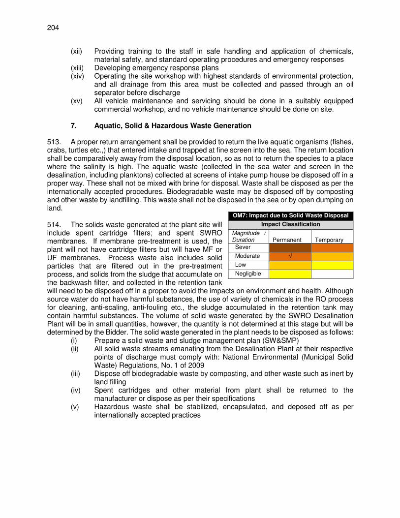
204
(xii) Providing training to the staff in safe handling and application of chemicals, material safety, and standard operating procedures and emergency responses
(xiii) Developing emergency response plans (xiv) Operating the site workshop with highest standards of environmental protection,
and all drainage from this area must be collected and passed through an oil separator before discharge
(xv) All vehicle maintenance and servicing should be done in a suitably equipped commercial workshop, and no vehicle maintenance should be done on site.
7. Aquatic, Solid & Hazardous Waste Generation
513. A proper return arrangement shall be provided to return the live aquatic organisms (fishes, crabs, turtles etc.,) that entered intake and trapped at fine screen into the sea. The return location shall be comparatively away from the disposal location, so as not to return the species to a place where the salinity is high. The aquatic waste (collected in the sea water and screen in the desalination, including planktons) collected at screens of intake pump house be disposed off in a proper way. These shall not be mixed with brine for disposal. Waste shall be disposed as per the internationally accepted procedures. Biodegradable waste may be disposed off by composting and other waste by landfilling. This waste shall not be disposed in the sea or by open dumping on land. 514. The solids waste generated at the plant site will include spent cartridge filters; and spent SWRO membranes. If membrane pre-treatment is used, the plant will not have cartridge filters but will have MF or UF membranes. Process waste also includes solid particles that are filtered out in the pre-treatment process, and solids from the sludge that accumulate on the backwash filter, and collected in the retention tank will need to be disposed off in a proper to avoid the impacts on environment and health. Although source water do not have harmful substances, the use of variety of chemicals in the RO process for cleaning, anti-scaling, anti-fouling etc., the sludge accumulated in the retention tank may contain harmful substances. The volume of solid waste generated by the SWRO Desalination Plant will be in small quantities, however, the quantity is not determined at this stage but will be determined by the Bidder. The solid waste generated in the plant needs to be disposed as follows:
(i) Prepare a solid waste and sludge management plan (SW&SMP) (ii) All solid waste streams emanating from the Desalination Plant at their respective
points of discharge must comply with: National Environmental (Municipal Solid Waste) Regulations, No. 1 of 2009
(iii) Dispose off biodegradable waste by composting, and other waste such as inert by land filling
(iv) Spent cartridges and other material from plant shall be returned to the manufacturer or dispose as per their specifications
(v) Hazardous waste shall be stabilized, encapsulated, and deposed off as per internationally accepted practices
OM7: Impact due to Solid Waste Disposal
Impact Classification
Magnitude / Duration
Permanent
Temporary
Sever
Moderate √
Low
Negligible

205
8. Domestic Wastewater Generation
515. During the operation phase, domestic wastewater (including sullage and sewage) will be generated from the plant, administrative and residential areas of the RO plant. It is estimated that a total of 28 staff will be required to operate the plant. Project includes construction of 6 number of quarters at plant to cater to the families of for staff working at the plant. Besides, there will be a circuit bungalow with 4 bedrooms to accommodate visitors. There is no estimate at this stage on the quantity of domestic wastewater generated, but a rough estimate indicates that it will be to the tune of 5 m3 per day. Bidding document requires that wastewater (other than brine from RO operations) including sanitary drainage from the facility shall be collected on site and disposed off via septic tank located at the plant site. Drainage waste shall not be released to the seawater. Period testing of septic tank effluent will be carried out. Considering these provision no impact envisaged due to generation of domestic waste.
9. Source water quality
516. Existing sea water quality at and around the proposed intake point has been studies in detail. A very wide range of determinants were analysed, 74 in total, including all of the standard physical and chemical parameters, plus 12 heavy metals and 35 pesticide residues. The results are provided in Appendix H and these indicate that seawater quality at the project site is good, with low values of suspended solids (< 2 mg/l) and organic matter (< 5 mg/l 5-day BoD), and no evidence of pollution by oil and grease, heavy metals, faecal bacteria or pesticides. The results also suggest a well-mixed and quite dynamic marine environment, with few differences in water quality throughout the water column. 517. The propose intake site is located in a remote area with relatively low population, and limited agriculture. There are no industries in the area. Therefore there are no potential sources of water pollution, and therefore sea water quality at the site is good, which is reflected in the water quality results. 518. During heavy rain events of the monsoon season intake will be influenced by surface runoff water delivered to the intake area with the near-shore winds, currents and tides. Considering the future development of agricultural and residential areas in and around the project site, runoff from these areas may cause anthropogenic contamination of sea water. The main anthropogenic contaminants that could reach the plant’ intakes are fertilizers, raw wastewater from flooded and inundated latrines and septic pits; heavy metals, oil and grease from parking areas, and pathogens. The plant and intake site has been chosen to be as remote as practical from the surface runoff from land based activities. Surface runoff in the vicinity of the plant is small due to the topography of the land. In addition, the water from which the source water is taken is active, relatively deep and 800m off shore. The current water quality data do not point out to hydrocarbon contamination, however, if the development around the plant is significant in future, source water could potentially contain hydrocarbons originating from latrine/septic tank discharges or form surface runoff.
OM8: Impact due to Domestic Wastewater
Impact Classification
Magnitude / Duration
Permanent
Temporary
Sever
Moderate
Low
Negligible √
OM9: Poor source water quality
Impact Classification
Magnitude / Duration
Permanent
Temporary
Sever
Moderate
Low √
Negligible
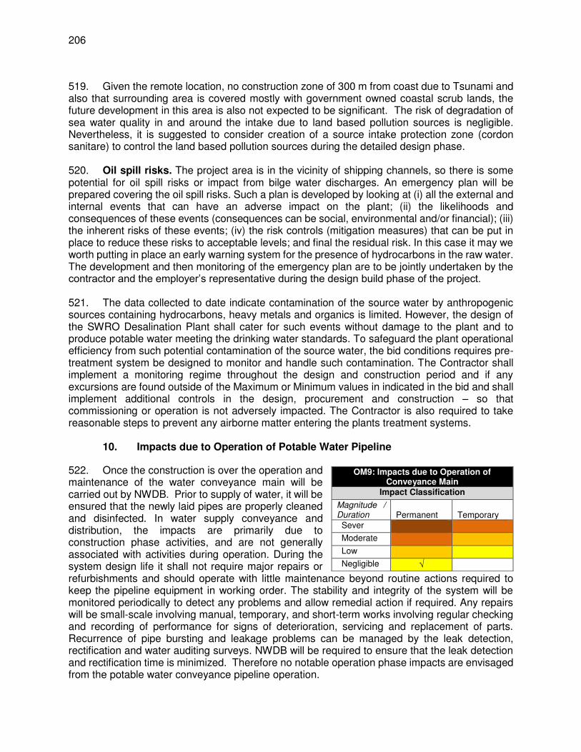
206
519. Given the remote location, no construction zone of 300 m from coast due to Tsunami and also that surrounding area is covered mostly with government owned coastal scrub lands, the future development in this area is also not expected to be significant. The risk of degradation of sea water quality in and around the intake due to land based pollution sources is negligible. Nevertheless, it is suggested to consider creation of a source intake protection zone (cordon sanitare) to control the land based pollution sources during the detailed design phase. 520. Oil spill risks. The project area is in the vicinity of shipping channels, so there is some potential for oil spill risks or impact from bilge water discharges. An emergency plan will be prepared covering the oil spill risks. Such a plan is developed by looking at (i) all the external and internal events that can have an adverse impact on the plant; (ii) the likelihoods and consequences of these events (consequences can be social, environmental and/or financial); (iii) the inherent risks of these events; (iv) the risk controls (mitigation measures) that can be put in place to reduce these risks to acceptable levels; and final the residual risk. In this case it may we worth putting in place an early warning system for the presence of hydrocarbons in the raw water. The development and then monitoring of the emergency plan are to be jointly undertaken by the contractor and the employer’s representative during the design build phase of the project. 521. The data collected to date indicate contamination of the source water by anthropogenic sources containing hydrocarbons, heavy metals and organics is limited. However, the design of the SWRO Desalination Plant shall cater for such events without damage to the plant and to produce potable water meeting the drinking water standards. To safeguard the plant operational efficiency from such potential contamination of the source water, the bid conditions requires pre-treatment system be designed to monitor and handle such contamination. The Contractor shall implement a monitoring regime throughout the design and construction period and if any excursions are found outside of the Maximum or Minimum values in indicated in the bid and shall implement additional controls in the design, procurement and construction – so that commissioning or operation is not adversely impacted. The Contractor is also required to take reasonable steps to prevent any airborne matter entering the plants treatment systems.
10. Impacts due to Operation of Potable Water Pipeline
522. Once the construction is over the operation and maintenance of the water conveyance main will be carried out by NWDB. Prior to supply of water, it will be ensured that the newly laid pipes are properly cleaned and disinfected. In water supply conveyance and distribution, the impacts are primarily due to construction phase activities, and are not generally associated with activities during operation. During the system design life it shall not require major repairs or refurbishments and should operate with little maintenance beyond routine actions required to keep the pipeline equipment in working order. The stability and integrity of the system will be monitored periodically to detect any problems and allow remedial action if required. Any repairs will be small-scale involving manual, temporary, and short-term works involving regular checking and recording of performance for signs of deterioration, servicing and replacement of parts. Recurrence of pipe bursting and leakage problems can be managed by the leak detection, rectification and water auditing surveys. NWDB will be required to ensure that the leak detection and rectification time is minimized. Therefore no notable operation phase impacts are envisaged from the potable water conveyance pipeline operation.
OM9: Impacts due to Operation of Conveyance Main
Impact Classification
Magnitude / Duration
Permanent
Temporary
Sever
Moderate
Low
Negligible √

207
11. Impacts due to Poor Operation & Maintenance Practices
523. Operation of the RODP as the state-of-the art modern facility that it is intended to be, will depend primarily on the calibre of the chosen contractor and the quality of the contractor’s design and operations teams, along with the quality and diligence of the supervising consultant and the client’s team. Given the fact that this is a Category A project, with some potentially significant impacts and possibly some rare species for which special mitigation may need to be designed and implemented, NWSDB should ensure that all teams, including their own, include highly dedicated and experienced environmental and social specialists, to ensure that environmental and social matters are dealt with appropriately and sensitively throughout. Following measures are already included in the bidding documents to ensure that RODP operation at all times meet highest industry standards.
(i) Ensuring that a well-qualified and experience contractor is engaged through proper bidding conditions and process
(ii) Preparing and implementing various operational safety plans to ensure high quality, professional organisation of RODP operation
(iii) Ensuring that O&M manuals, RODP H&S Plan, Process Safety Management Plan, Risk Management Plan, Facilities Safety and Security Plan, and the necessary programmes for compliance with all other applicable safety regulations, are all prepared by individuals with appropriate qualifications and extensive experience.
(iv) Ensuring that the above plans and other plans and programmes, and indeed all of the work tasks involved in operating the RODP are thoroughly and professionally implemented at all times by Plant Manager
(v) Ensuring that all of the mitigation measures discussed in this Chapter, and described along with implementation activities and schedules in Chapter X (Environmental Management Plan), are implemented in full, in the manner described.
524. There are also areas in which the operating plant could provide some additional benefits to the local community; and these should be implemented in order to compensate for the disturbance and disruption local people will inevitably experience, despite the multiple actions to minimise these impacts. These are as follows:
(i) The most important action is for NWSDB to ensure that each of the local villages is provided with a piped supply of high quality drinking water from the RODP; and this should be piped into individual houses if possible;
(ii) The contractor should provide local people with long-term employment in the plant operations workforce, and as in the construction stage, this should include disadvantaged persons and households to the extent possible;
(iii) Also as done in the construction stage, the contractor should obtain materials and services locally as much as possible, in order to provide some further socio-economic benefits in addition to the significant health and lifestyle improvements that will accrue from the provision of piped water supplies.
OM10: Impacts due to Poor Operation & Maintenance of RODP
Impact Classification
Magnitude / Duration
Permanent
Temporary
Sever
Moderate
Low √
Negligible

208
E. Project Green House Gas (GHG) Emissions
525. Power demand. According to the Feasibility Report (Appendix E2), the estimated average RO plant power use is 3.20 kWh/m3, while the average power demand is estimated as 3.84 MW. The maximum electric power use is 4.00 kWh/m3, which corresponds to a total maximum power demand of 4.80 MW. Based on this analysis, it is proposed to design the desalination plant electrical substation for a total load of 5.0 MW. Approximately 62 % of the total power use (2.2 kWh/m3) is associated with the operation of the SWRO membrane desalination system, followed by the intake pump station (8%). 526. Power supply. Power supply to the project will be from the national grid maintained by Ceylon Electricity Board (CEB), a national government entity. A dedicated line will be provided to the plant from the nearest grid network at Maruthenkerny (about 1-2 km from site) to ensure uninterrupted power supply. In Sri Lanka power generation is mainly from thermal and hydro power plants, and approximately in the ratio of 60:40, in terms of installed capacity.147 527. GHG Emissions. Following table shows the annual GHG emissions, estimated based on published grid emission factors148 and estimated power demand of the project. Power transmission and distribution losses149 also considered in CO2 emission estimates.
Table 36: CO2 Emissions from RODP Operations Particulars Units Present Plant Capacity Future Plant capacity
Plant production capacity m3/day 24,000 48,000 Max electricity consumption MWh/year 35,040 70,080 Grid emission factor tCO2/MWh 0.7689 0.7689 Annual CO2 emissions tCO2/year 30,443 60,886
F. Cumulative and Induced Impacts
528. The cumulative impacts150 are defined as the combination of multiple impacts from existing project, the proposed project, and anticipated future projects that may result in significant adverse and/or beneficial impacts that cannot be expected in the case of a stand-alone project. The induced impacts are the adverse and/or beneficial impacts on areas and communities from unintended but predictable development caused by a project, which may occur later or at a different location. 529. RODP will come up near Thalaiyadi, about 30 km from Jaffna, a fishing village on east coast. The natural resources that will be used by project is common coastal scrub land, and the open sea. RODP will be developed on the coastal scrub land of 5 ha, while the open sea will be the resource for abstraction of raw water and also for disposal of brine concentrate. The sea water abstraction will be the tune of 53,333 m3/day (to meet the present potable water demand of 24,000 m3.day) to 106,667 m3/day (ultimate demand of 48,000 m3/day) and disposal of brine will be in the tune of 34,667 m3/day (present demand) to 69,333 m3/day (ultimate demand). 530. The impacts of the project on scrub land, sea and the coastal, terrestrial and marine ecosystems have been identified and assessed in the previous sections. There are no existing or proposed desalination projects in the project area, Jaffna Peninsula or in the surrounding
147 Ceylon Electricity Board (2016). Long Term Generation Expansion Plan 2015-2034. 148 Grid emission factor (combined margin) 2015 data obtained from: http://www.info.energy.gov.lk/ 149 T&D loss data sourced from: http://powermin.gov.lk/english/?p=3172 150 ADB (2012). Environment Safeguards – A Good Practice Sourcebook

209
provinces. Though the current development of plant capacity is 24,000 m3/day, the future increase in capacity to 48,000 m3/day has already been considered in this EIA. Considering that the future demand of Jaffna to be met by desalination process is already included in the EIA no further development is anticipated. 531. There are no coastal or sea-based development project proposed in the vicinity of RODP project site at Thaliayadi. A proposal for development of Fishing Harbour at Point Pedro151 on the east coast, about 25-30 km north of Thaliayadi, is under consideration, and as per the available information, Government of Sri Lanka is in discussion with the ADB for funding this project. This project aims at reviving the fishing economy and development of fishing communities in Jaffna Peninsula, which was declined drastically due to 3 decades of civil war. Government intends to support local fishing communities through this project to adopt modern and efficient fishing practices using appropriate fishing gear and boats. Given the distance of 25-30 km, no notable impacts envisaged. It is no likely to affect raw water intake or brine disposal. There projects will be positive impacts on health and economic wellbeing of the people. 532. The RODP plant site is located in the interior coastal area, away from the developed areas of Jaffna. Nearest village, Thaliayadi, a small fishing village, is at about 500 m from the site. Site and surroundings are characterized by coastal scrub lands under the government ownership. There is no proposal to use these lands for any other development activity, however, some lands adjoining Thaliayady village may be used for its future expansion requirements, if government intends to provide government land for housing. This is natural development and not because of the development of RODP plant. As the RODP is a standalone and site confining activity, there is no likely induced development because of RODP operation. Workforce in the plant will be very limited. 533. RODP plant site will be connected by 2 new access roads of around 500 m each – one connecting it to Soranpattu – Thalaiyadi Road via an internal roadin Thalaiyadi existing road, and second connecting it to Mamune Road. Besides providing Plant connectity, new roads will improve connectivity of Thaliyadi village to Mamune road. This may bring some convenience local people and is a positive impact. These new roads are entirely located in government owned scrub lands, and therefore there will not be any induced development along these roads. 534. With the end of civil war in 2009, Jaffna district is experiencing rapid socio economic and infrastructure development. Current water supply service in Jaffna is intermittent, partially covered and overall it is unreliable. With construction of RODP, the water supply situation in Jaffna will improve significantly to about 300,000 population (which is about 45%). The improvement in water supply will enhance living conditions, and lead to larger benefits on public health and socio economic development, which is a positive impact on the project area. As the RODP project site is located far away from Jaffna and in an interior location, no anticipated induced development due to water supply improvement. Provision of water supply in local villages will have positive impacts. G. Environmental Impact Matrix
535. Table 37 presents the environmental matrix summarising the identified impacts, their predicted magnitude and duration along with the suggested mitigation measures, and responsible agencies.
151 http://www.ft.lk/article/620777/Govt--to-establish-largest-fisheries-harbour-in-Point-Pedro

210
Table 37: Environmental Impact Matrix Potential Impact
Nature of
Impact
Magnitude of Impact
Mitigation Measures Implementation &
monitoring
Impacts on protected (national) marine species
Permanent & irreversible
Low Translocate the four protected species (the hard and soft coral, tube anemone, Cerianthus sp, and Gorgonians) that are present along the route of the intake and outfall to a safer place with similar benthic habitat.
Adopt non-discriminatory approach as far as possible to relocate all species in the area of concern irrespective of conservation status
Obtain permission from the Central Environment Authority (CEA) for translocation Translocation work to be conducted by a reputed and competent agency in the field of wildlife conservation
with previous marine translocation experience in Sri Lanka Translocation should be done immediately before the marine trenching work begins, and it should cover
50 m strip along the pipelines alignment and 50 m around intake and outfall
Pre-construction and constriction phase
Impacts on protected flora species
Permanent & reversible
Low Conduct a confirmatory survey by an Ecologist to identify and mark, if any, protected plant species (4 plant species reported from surrounding area: Sesuvium portulacastrum, Halosarcia indica, Salicornia brachiate and Citrullus colocynthis) on site and also on the site survey maps.
Integrate identified protected plants in the layout design of RODP to avoid the need to remove/cut these plants
If unavoidable, translocate protected species in the nearby scrub land; prepare Tree Translocation, Cutting & Replantation Plan If translocation is not possible, and if it is necessary to remove/cut protected plants, prepare a justification to establish that it is not feasible to avoid or translocate plant
Obtain approval of competent authority for cutting/removal and plant 5 trees of same species for each tree that is removed
Pre-construction and constriction phase
Loss of coastal scrub land,
Permanent & irreversible
Low Adopt minimal tree cutting as a general principle in planning & design; minimize tree cutting – either of protected species or otherwise
In general, follow avoidance and compensatory approach for cutting of tree species; plant 2 trees for each tree removed
Develop a 3-5 m green buffer zone around the plant (within the facility or just outside the boundary wall) with local tree species to shield the plant’s visibility, so that the scrub land around the plant is used as in the existing condition without any perceived intrusion by fauna
Plant Operation & maintenance manual shall include clear provisions on protection and conservation of environment & wildlife, including prohibition on cutting of trees, removal of shrubs and bushes, hunting / harming wild animals etc.; do’s and don’ts to be followed by all concerned with RODP
Pre-construction and constriction phase
Impacts on protected species of avifauna
Permanent & irreversible
Low Conduct field surveys by an ecologist (6 months prior to start of work) to confirm if there are any birds of protected species (painted stork, and spot-billed pelican), and identify if any trees with nests / breeding places:
If there are birds any of these species on trees within the site, but no nests, ensure that the birds are not harmed, and allowed to move away freely
If there are any trees with nests / breeding birds, work shall not commence until nesting cycle is complete and the birds leave the nest
Pre-construction and constriction phase
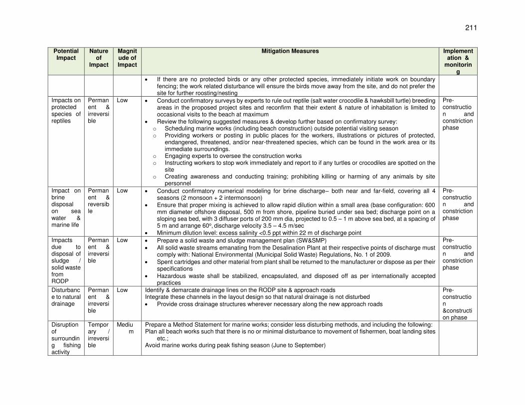
211
Potential Impact
Nature of
Impact
Magnitude of Impact
Mitigation Measures Implementation &
monitoring
If there are no protected birds or any other protected species, immediately initiate work on boundary fencing; the work related disturbance will ensure the birds move away from the site, and do not prefer the site for further roosting/nesting
Impacts on protected species of reptiles
Permanent & irreversible
Low Conduct confirmatory surveys by experts to rule out reptile (salt water crocodile & hawksbill turtle) breeding areas in the proposed project sites and reconfirm that their extent & nature of inhabitation is limited to occasional visits to the beach at maximum
Review the following suggested measures & develop further based on confirmatory survey: o Scheduling marine works (including beach construction) outside potential visiting season o Providing workers or posting in public places for the workers, illustrations or pictures of protected,
endangered, threatened, and/or near-threatened species, which can be found in the work area or its immediate surroundings.
o Engaging experts to oversee the construction works o Instructing workers to stop work immediately and report to if any turtles or crocodiles are spotted on the
site o Creating awareness and conducting training; prohibiting killing or harming of any animals by site
personnel
Pre-construction and constriction phase
Impact on brine disposal on sea water & marine life
Permanent & reversible
Low Conduct confirmatory numerical modeling for brine discharge– both near and far-field, covering all 4 seasons (2 monsoon + 2 intermonsoon)
Ensure that proper mixing is achieved to allow rapid dilution within a small area (base configuration: 600 mm diameter offshore disposal, 500 m from shore, pipeline buried under sea bed; discharge point on a sloping sea bed, with 3 diffuser ports of 200 mm dia, projected to 0.5 – 1 m above sea bed, at a spacing of 5 m and arrange 60o, discharge velocity 3.5 – 4.5 m/sec
Minimum dilution level: excess salinity <0.5 ppt within 22 m of discharge point
Pre-construction and constriction phase
Impacts due to disposal of sludge / solid waste from RODP
Permanent & irreversible
Low Prepare a solid waste and sludge management plan (SW&SMP) All solid waste streams emanating from the Desalination Plant at their respective points of discharge must
comply with: National Environmental (Municipal Solid Waste) Regulations, No. 1 of 2009. Spent cartridges and other material from plant shall be returned to the manufacturer or dispose as per their
specifications Hazardous waste shall be stabilized, encapsulated, and disposed off as per internationally accepted
practices
Pre-construction and constriction phase
Disturbance to natural drainage
Permanent & irreversible
Low Identify & demarcate drainage lines on the RODP site & approach roads Integrate these channels in the layout design so that natural drainage is not disturbed Provide cross drainage structures wherever necessary along the new approach roads
Pre-construction &construction phase
Disruption of surrounding fishing activity
Temporary / irreversible
Medium
Prepare a Method Statement for marine works; consider less disturbing methods, and including the following: Plan all beach works such that there is no or minimal disturbance to movement of fishermen, boat landing sites
etc.; Avoid marine works during peak fishing season (June to September)
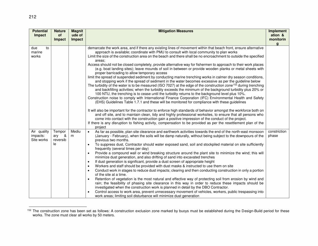
212
Potential Impact
Nature of
Impact
Magnitude of Impact
Mitigation Measures Implementation &
monitoring
due to marine works
demarcate the work area, and if there any existing lines of movement within that beach front, ensure alternative approach is available; coordinate with PMU to consult with local community to plan works
Limit the size of the construction area on the beach and there shall be no encroachment to outside the specified areas;
Access should not be closed completely, provide alternative way for fishermen to approach to their work places (e.g. boat landing sites); leave mounds of soil in between or provide wooden planks or metal sheets with proper barricading to allow temporary access
limit the spread of suspended sediment by conducting marine trenching works in calmer dry season conditions, and stopping work if the spread of sediment in the water becomes excessive as per the guideline below
The turbidity of the water is to be measured (ISO 7027) at the edge of the construction zone152 during trenching and backfilling activities; when the turbidity exceeds the minimum of the background turbidity plus 20% or 100 NTU, the trenching is to cease until the turbidity returns to the background level plus 10%.
Construction noise to comply with International Finance Corporation (IFC) Environmental Health and Safety (EHS) Guidelines Table 1.7.1 and these will be monitored for compliance with these guidelines
It will also be important for the contractor to enforce high standards of behavior amongst the workforce both on
and off site, and to maintain clean, tidy and highly professional worksites, to ensure that all persons who come into contact with the construction gain a positive impression of the conduct of the project.
If there is any disruption to fishing activity, compensation to be provided as per the resettlement plan of the project
Air quality impacts: Site works
Temporary & reversible
Medium
As far as possible, plan site clearance and earthwork activities towards the end of the north-east monsoon (January - February), when the soils will be damp naturally, without being subject to the downpours of the previous two months.
To suppress dust, Contractor should water exposed sand, soil and stockpiled material on site sufficiently frequently (several times per day)
Provide a compound wall or wind breaking structure around the plant site to minimize the wind; this will minimize dust generation, and also drifting of sand into excavated trenches
If dust generation is significant, provide a dust screen of appropriate height Workers and staff should be provided with dust masks & instructed to use them on site Conduct work in stages to reduce dust impacts; clearing and then conducting construction in only a portion
of the site at a time. Retention of vegetation is the most natural and effective way of protecting soil from erosion by wind and
rain; the feasibility of phasing site clearance in this way in order to reduce these impacts should be investigated when the construction work is planned in detail by the DBO Contractor.
Control access to work area, prevent unnecessary movement of vehicles, workers, public trespassing into work areas; limiting soil disturbance will minimize dust generation
constriction phase
152 The construction zone has been set as follows: A construction exclusion zone marked by buoys must be established during the Design-Build period for these
works. The zone must clear all works by 50 meters.
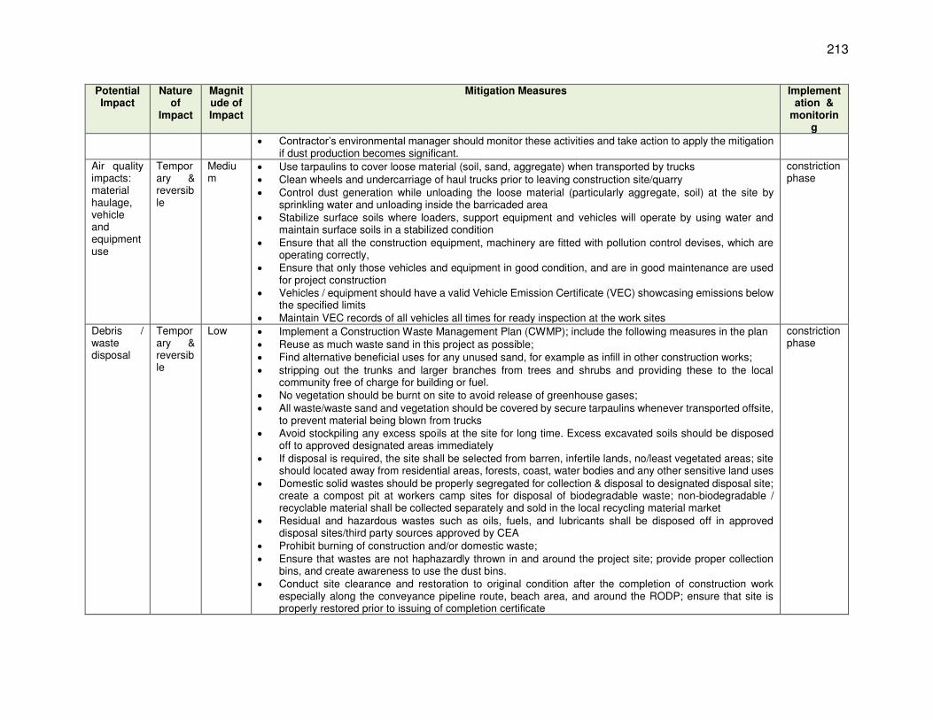
213
Potential Impact
Nature of
Impact
Magnitude of Impact
Mitigation Measures Implementation &
monitoring
Contractor’s environmental manager should monitor these activities and take action to apply the mitigation if dust production becomes significant.
Air quality impacts: material haulage, vehicle and equipment use
Temporary & reversible
Medium
Use tarpaulins to cover loose material (soil, sand, aggregate) when transported by trucks Clean wheels and undercarriage of haul trucks prior to leaving construction site/quarry Control dust generation while unloading the loose material (particularly aggregate, soil) at the site by
sprinkling water and unloading inside the barricaded area Stabilize surface soils where loaders, support equipment and vehicles will operate by using water and
maintain surface soils in a stabilized condition Ensure that all the construction equipment, machinery are fitted with pollution control devises, which are
operating correctly, Ensure that only those vehicles and equipment in good condition, and are in good maintenance are used
for project construction Vehicles / equipment should have a valid Vehicle Emission Certificate (VEC) showcasing emissions below
the specified limits Maintain VEC records of all vehicles all times for ready inspection at the work sites
constriction phase
Debris / waste disposal
Temporary & reversible
Low Implement a Construction Waste Management Plan (CWMP); include the following measures in the plan Reuse as much waste sand in this project as possible; Find alternative beneficial uses for any unused sand, for example as infill in other construction works; stripping out the trunks and larger branches from trees and shrubs and providing these to the local
community free of charge for building or fuel. No vegetation should be burnt on site to avoid release of greenhouse gases; All waste/waste sand and vegetation should be covered by secure tarpaulins whenever transported offsite,
to prevent material being blown from trucks Avoid stockpiling any excess spoils at the site for long time. Excess excavated soils should be disposed
off to approved designated areas immediately If disposal is required, the site shall be selected from barren, infertile lands, no/least vegetated areas; site
should located away from residential areas, forests, coast, water bodies and any other sensitive land uses Domestic solid wastes should be properly segregated for collection & disposal to designated disposal site;
create a compost pit at workers camp sites for disposal of biodegradable waste; non-biodegradable / recyclable material shall be collected separately and sold in the local recycling material market
Residual and hazardous wastes such as oils, fuels, and lubricants shall be disposed off in approved disposal sites/third party sources approved by CEA
Prohibit burning of construction and/or domestic waste; Ensure that wastes are not haphazardly thrown in and around the project site; provide proper collection
bins, and create awareness to use the dust bins. Conduct site clearance and restoration to original condition after the completion of construction work
especially along the conveyance pipeline route, beach area, and around the RODP; ensure that site is properly restored prior to issuing of completion certificate
constriction phase

214
Potential Impact
Nature of
Impact
Magnitude of Impact
Mitigation Measures Implementation &
monitoring
Water quality
Temporary & reversible
Low Avoid earthworks during monsoon season to prevent the problem of soil run-off Avoid stockpiling of earth fill during the monsoon season unless covered by tarpaulins or plastic sheets Dispose spoils in designated disposal areas only Install temporary silt traps or sedimentation basins along drainage leading to water bodies Place storage areas for fuels & lubricants away from any drainage leading to water bodies Store fuel, construction chemicals etc., on an impervious floor, also avoid spillage Conduct surface quality inspection according to monitoring plan Pump out the water collected in the pits / excavations to a temporary sedimentation basin dispose off only
clarified water into drainage channels/streams Consider safety aspects related to trench /pit collapse due to accumulation of water Conduct water quality monitoring as per EMP
constriction phase
Vadamarachchi lagoon water quality
Temporary & reversible
Low Prepare a method statement following internationally accepted construction procedures in wetlands. This inter alia include pollution control (water, air, noise), limiting disturbance, unharming wildlife etc.,
Schedule works during low water level in the lagoon; no works be scheduled during September to March (migratory season for birds)
Lower the precast pipe slowly to allow any aquatic organism below it to move away; also avoid any unnecessary disturbance to the still water
Water, slurry (silt / sand mixed with water) collected in the lowered pipe shall not be pumped/disposed back directly into the lagoon; this should be pumped to a temporary sedimentation basin or tank; after proper settling in the basin, clarified water can be let into lagoon by surface discharge (not to be pumped directly into the lagoon; collected sand and silt be utilized in the construction and shall not be disposed off in the lagoon
No spillage of oil, grease, chemicals etc., into the lagoon Dispose any residuals at identified disposal site Stock pile construction material away from the lagoon area Develop a Concrete Spill Prevention and Containment Plan, educate workers about the plan, and have the
necessary materials on site prior to and during construction Ensure that no equipment/material /workers, except the precast pipe that is lowered into water, comes in
contact with water; this should strictly be prevented Do not conduct any cleaning, washing, rinsing of concrete or other equipment near the lagoon; prevent any
waste / water from discharging into the lagoon. Refuel equipment within the designated refueling containment area away from the lagoon Inspect all vehicles daily for fluid leaks before leaving the vehicle staging area, and repair any leaks before
the vehicle resumes operation Ensure that no silt laden runoff from nearby construction area (pipeline construction sites) enter the lagoon;
this can be avoided by scheduling the construction work around the lagoon area in non-monsoon; to accommodate for untimely rains, contractor should provide silt traps as required
Excess water sprinkling on soil, material to control dust may also generate runoff which may enter the lagoon; this should be avoided by controlled water sprinkling
constriction phase

215
Potential Impact
Nature of
Impact
Magnitude of Impact
Mitigation Measures Implementation &
monitoring
Conduct water quality monitoring as per EMP Pollution from concrete batching plant operations
Temporary & reversible
Low Ensure that batching plant is installed with in-built air pollution and dust control system; for fugitive emissions /dust from loading area, provide dust screen around the components
Ensure that plant is well operated & maintained at all times according to O&M manuals provided by the equipment manufacturer;
The concrete loading area is equipped with a leak-proof concrete floor, from which all drainage is collected and treated as necessary prior to discharge
Mixer trucks and especially mixer drums are washed out only in a designated area, which should also be equipped with a leak-proof floor, from which drainage is collected and treated as necessary
All chemicals used in concrete preparation are properly stored, whether dry, in powder or granular form, or as liquids. Storage facilities should be as specified in the appropriate international standard, and should include equipment to extract dust and completely contain any spillage from leaks
constriction phase
Construction noise & vibration
Temporary & reversible
Medium
Do not conduct activities (pipe laying) in and around lagoon area (lagoon section (1.3 km) + 0.5 km on both the sides) during September to March period; works at this stretch may be immediately conducted during the following intermonsoon season and completed
Do not conduct any high noise generating activities near lagoon; conduct regular monitoring of noise levels as per the monitoring plan
Limit construction activities to day time only Noise level at the boundary of site shall not exceed 70 dB(A) during day and 50 dB(A) during night Minimize noise from construction equipment by using vehicle silencers, fitting jackhammers with noise-
reducing mufflers, and use portable street barriers to minimize sound impact to surrounding sensitive receptor
Avoid loud random noise from sirens, air compression, etc. Avoid using multiple high noise generating equipment / activities simultaneously Install temporary or portable acoustic barriers around stationary construction noise sources Identify any buildings at risk from vibration damage and avoiding any use of pneumatic drills or heavy
vehicles in the vicinity (for pipeline works) Horns should not be used unless it is necessary Consult local communities in advance of the work to identify and address key issues, and avoid working at
sensitive times, such as religious and cultural festivals (for pipeline works) Conduct noise monitoring as per the EMP
constriction phase
Loss / damage to flora and fauna
Temporary & irreversible
Low Ensure that all construction activities are conducted strictly within the site footprint (including offices, car parking and other activities that might normally be located in an exterior contractor’s area); no clearance of vegetation/trees outside footprint is permitted
Prohibit any deliberate killing or harming of animals on or off-site; any hunting or fishing at the site or in nearby areas by site personnel; preventive actions shall be put in place by contractor for hunting/killing of wild animals
Ensure that all construction work or other activities near the site perimeter are conducted with particular care and include measures to reduce noise and dust to minimum possible
constriction phase

216
Potential Impact
Nature of
Impact
Magnitude of Impact
Mitigation Measures Implementation &
monitoring
Conduct the site clearance and earthworks in a phased manner, gradually advancing noise & visual disturbance, which will encourage animals to leave before their habitat is affected
Create awareness in all site staff & workers on the importance of the animals and plants on site and in the surrounding area, and their vulnerability
To protect site personnel, training should also be provided to enable them to recognize & deal safely & humanely wilt all venomous animals that may be encountered (e.g. snakes and scorpions)
Conduct site preparation activities, including vegetation removals, outside of the breeding season for wildlife, including migratory birds
Prevent access to areas located beyond the construction zone; fence and barricade the plant area with controlled entry and exit
Impacts on protected species of flora and fauna
Temporary & irreversible
Medium
Prepare a method statement following internationally accepted construction procedures in wetlands. This interalia include pollution control (water, air, noise), limiting disturbance, unharming wildlife etc.,
Create awareness among workers and site staff on wildlife and protected species Provide to workers or post in work area for the workers, illustrations or pictures of protected/ endangered
species, which can be found in the work area or its immediate surroundings Instruct workers to stop work immediately and report to supervisor/contractor’s environment specialist on
any on-site presence of protected/endangered species Conduct marine and beach works under the continuous monitoring of a Marine Biologist – (as far as the
same expert who conducted confirmatory survey) Conduct work in Vadamarachchi lagoon when the water level is very low; even if crocodiles are present in
Vadamarachchi lagoon, there is high likelihood of them moving to the main Thondamannaru lagoon, prior to the start of dry season Ensure the presence of ecologist to oversee the works in lagoon
constriction phase
Community safety & health
Temporary & irreversible
Low Work along public roads for conveyance pipeline Adopt standard and safe practices for trenching and pipe laying Ensure access to houses and business along the alignment; provide wooden planks, metal sheet with
protective barricades/rails to allow access to the properties Provide temporary traffic control (e.g. flagmen) & signs where necessary to improve safety and provide
directions Restrict public access to all areas where construction works are on-going through the use of barricading
and security personnel Ensure that all material, equipment, workers and all activities are conducted within the demarcated /
barricaded strip of land along the road; there should be no spillage of any activity outside this zone Clearly separate work area with traffic/pedestrian flow; provide public information boards to easily identify
the work area Warning signs, blinkers will be attached to the barricading to caution the public about the hazards
associated with the works such as presence of trenches / deep excavation Plan carefully using section-by-section approach, so that open trenches are quickly closed and road
restored
constriction phase
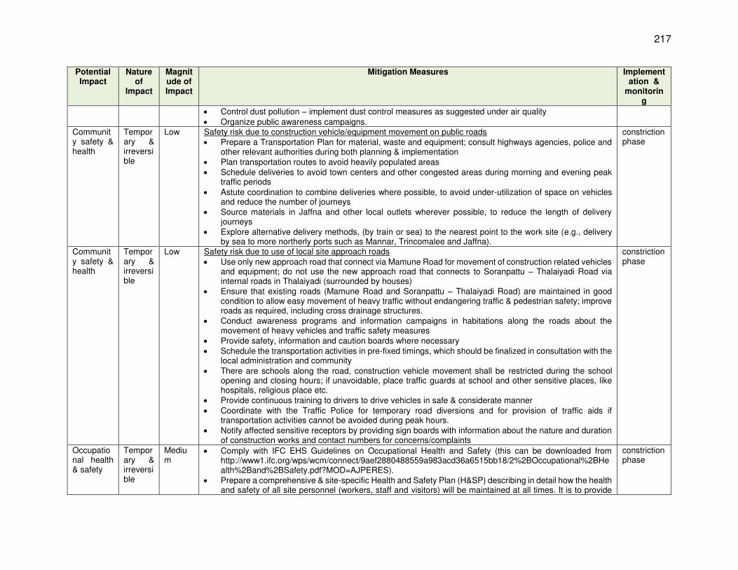
217
Potential Impact
Nature of
Impact
Magnitude of Impact
Mitigation Measures Implementation &
monitoring
Control dust pollution – implement dust control measures as suggested under air quality Organize public awareness campaigns.
Community safety & health
Temporary & irreversible
Low Safety risk due to construction vehicle/equipment movement on public roads Prepare a Transportation Plan for material, waste and equipment; consult highways agencies, police and
other relevant authorities during both planning & implementation Plan transportation routes to avoid heavily populated areas Schedule deliveries to avoid town centers and other congested areas during morning and evening peak
traffic periods Astute coordination to combine deliveries where possible, to avoid under-utilization of space on vehicles
and reduce the number of journeys Source materials in Jaffna and other local outlets wherever possible, to reduce the length of delivery
journeys Explore alternative delivery methods, (by train or sea) to the nearest point to the work site (e.g., delivery
by sea to more northerly ports such as Mannar, Trincomalee and Jaffna).
constriction phase
Community safety & health
Temporary & irreversible
Low Safety risk due to use of local site approach roads Use only new approach road that connect via Mamune Road for movement of construction related vehicles
and equipment; do not use the new approach road that connects to Soranpattu – Thalaiyadi Road via internal roads in Thalaiyadi (surrounded by houses)
Ensure that existing roads (Mamune Road and Soranpattu – Thalaiyadi Road) are maintained in good condition to allow easy movement of heavy traffic without endangering traffic & pedestrian safety; improve roads as required, including cross drainage structures.
Conduct awareness programs and information campaigns in habitations along the roads about the movement of heavy vehicles and traffic safety measures
Provide safety, information and caution boards where necessary Schedule the transportation activities in pre-fixed timings, which should be finalized in consultation with the
local administration and community There are schools along the road, construction vehicle movement shall be restricted during the school
opening and closing hours; if unavoidable, place traffic guards at school and other sensitive places, like hospitals, religious place etc.
Provide continuous training to drivers to drive vehicles in safe & considerate manner Coordinate with the Traffic Police for temporary road diversions and for provision of traffic aids if
transportation activities cannot be avoided during peak hours. Notify affected sensitive receptors by providing sign boards with information about the nature and duration
of construction works and contact numbers for concerns/complaints
constriction phase
Occupational health & safety
Temporary & irreversible
Medium
Comply with IFC EHS Guidelines on Occupational Health and Safety (this can be downloaded from http://www1.ifc.org/wps/wcm/connect/9aef2880488559a983acd36a6515bb18/2%2BOccupational%2BHealth%2Band%2BSafety.pdf?MOD=AJPERES).
Prepare a comprehensive & site-specific Health and Safety Plan (H&SP) describing in detail how the health and safety of all site personnel (workers, staff and visitors) will be maintained at all times. It is to provide
constriction phase

218
Potential Impact
Nature of
Impact
Magnitude of Impact
Mitigation Measures Implementation &
monitoring
guidance on establishing a management strategy and applying practices that are intended to eliminate, or reduce, fatalities, injuries and illnesses for workers performing activities and tasks associated with the project. It will be important to ensure that the H&SP:
o describes all construction work processes, examines their H&S risks fully and describes action to be taken to avoid accidents, with clearly allocated responsibility for each individual action;
o covers all construction sites and work areas, including road transportation, and includes measures to protect contractor’s employees, subcontractors’ employees and the general public;
o includes regular training for all site personnel in all aspects that are relevant to their work, with the content of and attendance at all training being accurately recorded and provided monthly to the client;
o allocates responsibility for maintenance of health and safety on and off site to an H&S Manager, who is a senior member of the site management team, and has a team working under him/her, who will inspect all worksites at least weekly and will be responsible for enforcing all relevant H&S procedures;
o requires all site employees to be provided with and use Personal Protective Equipment (PPE) that is appropriate to their work duties;
o requires the H&S Manager to keep records of all accidents and incidents with H&S implications, and the action taken, and to review these records periodically in order to learn lessons and implement preventative action;
o requires the H&S Manager to report monthly to the client on H&S training, accidents and incidents and remedial and preventative action in the month;
o it will also be important to ensure that the H&SP is not simply a document but provides a vehicle and process through which rigorously high standards of safety are enforced throughout the project as a matter of course.
Provide compulsory H&S orientation training to all new workers to ensure that they are apprised of H&S Plan including rules of work, PPE, preventing injury to fellow workers, etc.,.
Conduct regular tool box safety briefings; learning’s, causes, risks & safe procedures Conduct periodic safety audit, identify and remove potential hazard Ensure that qualified first-aid is provided at all times; equipped first-aid stations shall be easily accessible
throughout the work sites and camps. Provide medical insurance coverage to workers. Secure all installations from unauthorized intrusion and accident risks. Provide supplies of potable drinking water Provide clean eating areas where workers are not exposed to hazardous or noxious substances. Provide visitor orientation if visitors to the site can gain access to areas where hazardous conditions or
substances may be present; visitors not to enter hazard areas unescorted Ensure the visibility of workers through their use of high visibility vests when working in or walking through
heavy equipment operating areas Ensure moving equipment is outfitted with audible back-up alarms
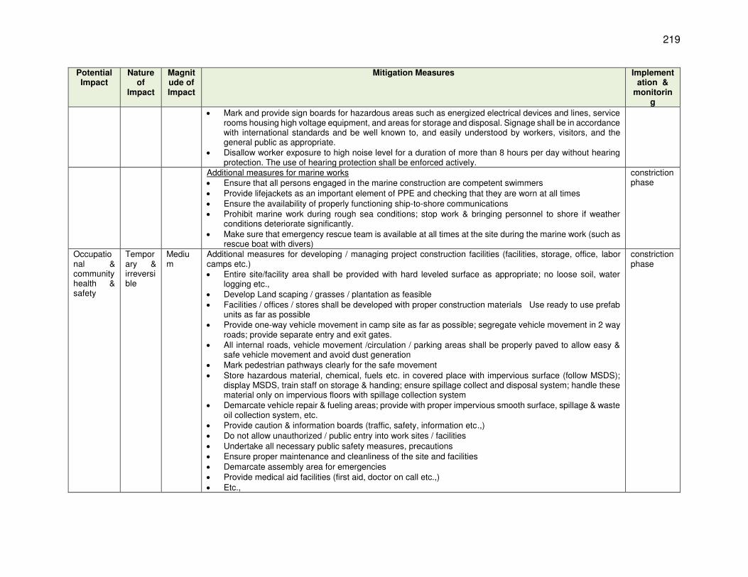
219
Potential Impact
Nature of
Impact
Magnitude of Impact
Mitigation Measures Implementation &
monitoring
Mark and provide sign boards for hazardous areas such as energized electrical devices and lines, service rooms housing high voltage equipment, and areas for storage and disposal. Signage shall be in accordance with international standards and be well known to, and easily understood by workers, visitors, and the general public as appropriate.
Disallow worker exposure to high noise level for a duration of more than 8 hours per day without hearing protection. The use of hearing protection shall be enforced actively.
Additional measures for marine works Ensure that all persons engaged in the marine construction are competent swimmers Provide lifejackets as an important element of PPE and checking that they are worn at all times Ensure the availability of properly functioning ship-to-shore communications Prohibit marine work during rough sea conditions; stop work & bringing personnel to shore if weather
conditions deteriorate significantly. Make sure that emergency rescue team is available at all times at the site during the marine work (such as
rescue boat with divers)
constriction phase
Occupational & community health & safety
Temporary & irreversible
Medium
Additional measures for developing / managing project construction facilities (facilities, storage, office, labor camps etc.) Entire site/facility area shall be provided with hard leveled surface as appropriate; no loose soil, water
logging etc., Develop Land scaping / grasses / plantation as feasible Facilities / offices / stores shall be developed with proper construction materials Use ready to use prefab
units as far as possible Provide one-way vehicle movement in camp site as far as possible; segregate vehicle movement in 2 way
roads; provide separate entry and exit gates. All internal roads, vehicle movement /circulation / parking areas shall be properly paved to allow easy &
safe vehicle movement and avoid dust generation Mark pedestrian pathways clearly for the safe movement Store hazardous material, chemical, fuels etc. in covered place with impervious surface (follow MSDS);
display MSDS, train staff on storage & handing; ensure spillage collect and disposal system; handle these material only on impervious floors with spillage collection system
Demarcate vehicle repair & fueling areas; provide with proper impervious smooth surface, spillage & waste oil collection system, etc.
Provide caution & information boards (traffic, safety, information etc.,) Do not allow unauthorized / public entry into work sites / facilities Undertake all necessary public safety measures, precautions Ensure proper maintenance and cleanliness of the site and facilities Demarcate assembly area for emergencies Provide medical aid facilities (first aid, doctor on call etc.,) Etc.,
constriction phase

220
Potential Impact
Nature of
Impact
Magnitude of Impact
Mitigation Measures Implementation &
monitoring
Impacts on marine ecosystem due to construction works on beach and sea
Temporary & reversible
Medium
Marine works should be scheduled to occur in the dry season (not the monsoon period) when the sea conditions are calmer to limit the spread of sediment around this operation
Conduct the excavation, and deposit the excavated material in a more controlled manner minimizing the area that is disturbed
Avoid the need to excavation by choosing right time (calmed sea conditions again), and quickly lowering the pipes into trench and refilling
It will also be important for the contractor to enforce high standards of behavior amongst the workforce both on and off site, and to maintain clean, tidy and highly professional worksites, to ensure that all persons who come into contact with the construction gain a positive impression of the conduct of the project
limit the size of the construction area on the beach and to avoid any encroachment outside the specified area
Monitor the turbidity & DO levels due to spread of sediment throughout the trenching operation, and work should be stopped if levels exceed pre-determined values as per the guideline below
The turbidity of the water is to be measured (ISO 7027) at the edge of the construction zone153 during trenching and backfilling activities; when the turbidity exceeds the minimum of the background turbidity plus 20% or 100 NTU, the trenching is to cease until the turbidity returns to the background level plus 10%.
Construction noise to comply with International Finance Corporation (IFC) Environmental Health and Safety (EHS) Guidelines Table 1.7.1 and these will be monitored for compliance with these guidelines
turbidity and DO levels should not deviate more than 10% from the ambient level outside 250 m boundary of the work site).
o
constriction phase
Impacts on fishermen
Temporary & irreversible
Low Conduct marine works with minimum disturbance as much as possible the spread of suspended sediment by conducting marine trenching works in calmer dry season conditions,
and stopping work if the spread of sediment in the water becomes excessive Turbidity and DO levels should not exceed 10% beyond 250 m boundary of the work site. Compensate for any loss of fishing activity during construction as per the resettlement plan of the project
constriction phase
Impacts of protected marine species
Permanent & irreversible
Negligible
Individuals of the four species protected by the FFPO were translocated before construction began and these species may have recolonized the discharge area. The relocation should be repeated before the RODP begins to operate, to protect these individuals
Adopt non-discriminatory approach as far as possible to relocate all species in the area of concern irrespective of conservation status
Engage specialist agency to translocate individuals of the four protected species immediately before plant operation begins. This should cover an area of 50 m radius around the outfall. All living individuals of the 4 species should be relocated into a safe area agreed by CEA and IUCN
Operation phase
153 The construction zone has been set as follows: A construction exclusion zone marked by buoys must be established during the Design-Build period for these
works. The zone must clear all works by 50 meters.

221
Potential Impact
Nature of
Impact
Magnitude of Impact
Mitigation Measures Implementation &
monitoring
Reengage the specialists to resurvey the translocation area after 3 and 5 years to determine survival of translocated individuals
Poor operation and maintenance practices
Permanent/ reversible
Low Ensuring that a well-qualified and experience contractor is engaged through proper bidding conditions and process
Preparing and implementing various operational safety plans to ensure high quality, professional organization of RODP operation
Ensuring that O&M manuals, RODP H&S Plan, Process Safety Management Plan, Risk Management Plan, Facilities Safety and Security Plan, and the necessary programmes for compliance with all other applicable safety regulations, are all prepared by individuals with appropriate qualifications and extensive experience.
Ensuring that the above plans and other plans and programmes, and indeed all of the work tasks involved in operating the RODP are thoroughly and professionally implemented at all times by Plant Manager
Ensuring that all of the mitigation measures discussed in this Chapter, and described along with implementation activities and schedules in Environmental Management Plan are implemented in full, in the manner described.
Operation phase
Intake operation in open sea
Permanent & irreversible
Negligible
Ensure that intake is operated as per the design (ensuring the horizontal flow and velocity within 0.15 m/sec Conduct monitoring of marine species infringed in the intakes Undertake corrective measures if required A proper return arrangement shall be provided to return the live aquatic organisms (fishes, crabs, turtles
etc.,) that entered intake and trapped at fine screen into the sea The return location shall be comparatively away from the disposal location, so as not to return the species
to a place where the salinity is high The aquatic waste (collected in the sea water and screen in the desalination, including planktons) collected
at screens of intake pump house be disposed as per the internationally accepted procedures. These waste shall not be mixed with brine for disposal or in the sea or by open dumping Biodegradable waste may be disposed off by composting and other waste by landfilling. Include the details
in monitoring reports for disclosure
Operation phase
Intake operation in open sea: impact on marine organisms & disposal of aquatic waste
Permanent & reversible
Negligible
A proper return arrangement shall be provided to return the live aquatic organisms (fishes, crabs, turtles etc.,) that entered intake and trapped at fine screen into the sea.
The return location shall be comparatively away from the disposal location, so as not to return the species to a place where the salinity is high.
The aquatic waste (collected in the sea water and screen in the desalination, including planktons) collected at screens of intake pump house be disposed off in a proper way.
These shall not be mixed with brine for disposal. Waste shall be disposed as per the internationally accepted procedures. Biodegradable waste may be disposed off by composting and other waste by landfilling. This waste shall
not be disposed in the sea or by open dumping on land.
Design, Construction & operation phase
Disposal of brine in open sea
Permanent &
Negligible
Ensure that outfall is operated as per the design (ensuring that dispersions is as according to numerical prediction
Conduct monitoring of sea water quality to ensure that dilution is achieved as intended
Operation phase

222
Potential Impact
Nature of
Impact
Magnitude of Impact
Mitigation Measures Implementation &
monitoring
irreversible
Undertake corrective measures if required Include the details in monitoring reports for disclosure
Source water quality – risk of quality degradation
Permanent & reversible
Low Review the need to create source protection zone (cordon sanitare) to control land based pollution source Emergency plan of the plant shall cover oil spill risks; Emergency plan shall be considering, inter alia: (i) all the external and internal events that can have an
adverse impact on the plant; (ii) the likelihoods and consequences of these events (consequences can be social, environmental and/or financial); (iii) the inherent risks of these events; (iv) the risk controls (mitigation measures) that can be put in place to reduce these risks to acceptable levels; and final the residual risk.
Design phase
Domestic waste generation: environment & health impacts
Permanent & reversible
Negligible
Measures already included in the project design to collect, treat and dispose the domestic wastewater safely
Operation phase
Noise from operations
Permanent & irreversible
Negligible
Shall not exceed the baseline noise levels (pre-project conditions) when measured at just outside the RODP premises (day time 50 dB(A) & night time 45 dB(A))
Ensure that all the equipment are operated and maintained as per the manufacturer specifications Immediately replace equipment not meeting the noise levels Conduct noise monitoring to confirm the compliance with set values
Operation phase
Light pollution from operation: impact on turtles
Permanent & irreversible
Negligible
Ensure that no light spill on to the beach or surroundings from the RODP plant
Operation phase
Operation of intake & outfall: Impact on fisheries and livelihoods
Permanent & irreversible
Negligible
Create awareness among the fishermen about the location of intake and outfall, and operational procedures
It is important to for local fishermen to under the exact operation at intake and outfall, and measures provided to avoid interference with fishing activity, net damage etc.,
which will help to nullify any negative views on the project If possible, provide firsthand information to fishing community by providing opportunity to a representative
of fishing community (who should know deep sea diving), to visit the site along with divers from the project Inform fishing community about the monitoring measures in place to study the impacts (refer EMP) Demarcate an area of around 50 m around the intake and outfall with visiting buoys; this boundary may be
narrowed down as suitable once the fishermen are familiar with the structures; this is to ensure that fishing nets are not damaged due to entangling with structures
In unlikely event of any damage to fishing net, compensation may be paid as per the resettlement plan
Operation phase
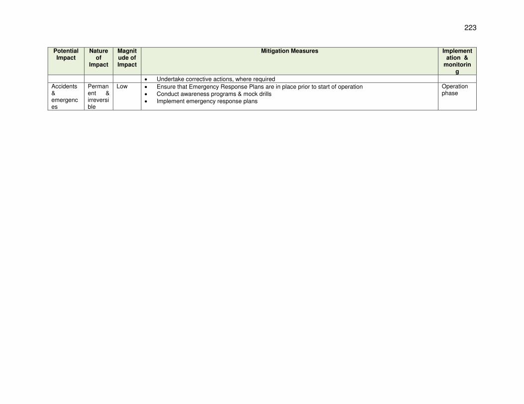
223
Potential Impact
Nature of
Impact
Magnitude of Impact
Mitigation Measures Implementation &
monitoring
Undertake corrective actions, where required Accidents & emergences
Permanent & irreversible
Low Ensure that Emergency Response Plans are in place prior to start of operation Conduct awareness programs & mock drills Implement emergency response plans
Operation phase

224
VII. PUBLIC CONSULTATION AND INFORMATION DISCLOSURE
A. Consultation by the Project Proponent
536. NWSDB has been very active in informing stakeholders about the JKWSP and engaging them in project development, both during the early stages of project planning and implementation of the Feasibility Study in 2005-06, and when the work was recommenced at the end of the civil war in 2009-10. Contacts were made through a variety of forums, including: focus group discussions on specific topics; structured meetings with a wider range of stakeholders; presentations to specific interest groups (eg farmers served by the Iranamadu irrigation scheme); and two public meetings at Kilinochchi and Jaffna on 17 and 18 February 2006, each attended by almost one hundred persons. Discussions inevitably focused on the issue of water-sharing in relation to the Iranamadu Tank, but other wider social and environmental issues were also raised. These discussions are summarised in Table 38 and described in detail in Chapter IX and Appendix 4 of the IEE for JKWSP.154
Table 38: Stakeholder Meetings - Jaffna Kilinochchi Water Supply & Sanitation Project Date Attendees Location Main topics discussed
25/4/05 All stakeholder representatives Jaffna Library Kick-off meeting; Inception Report 07/07/05 CAARP Coordination Committee Trincomalee Progress Report
17/07/05 Kilinochchi PDS and ID; Farmers’ organisation representatives
Kilinochchi Use of Iranamadu Tank for Jaffna drinking water supplies
27/07/05 MUDWS; Ministry of RRR; Irrigation Dept.; Water Resources Board
Ratmalana, Colombo
Interim Report
20/09/05 Kilinochchi PDS and ID; NEIAP Kilinochchi Iranamadu hydrology and Jaffna Peninsula groundwater modelling
14/10/05 CAARP Coordination Committee Trincomalee Progress Report
22/10/05 NSGD Association with SCISL Valvettithurai Presentation on water issues at exhibition on Socio-Economic Development Achievements
14/11/05 Kilinochchi ID; Farmers’ organisation representatives
Kilinochchi Use of Iranamadu Tank for Jaffna drinking water supplies; and MOU
30/11/05 CAARP Coordination Committee Trincomalee Progress Report 20/01/06 MUDWS; Chief Secretary NEP; ADB Ratmalana Draft Final Report
17/02/06 General Public; NGOs; Government officers
Kilinochchi Details of proposed project; stakeholder views and concerns
18/02/06 General Public; NGOs; Government officers
Kilinochchi Details of proposed project; stakeholder views and concerns
10/02/10 All Divisional Secretaries, Jaffna District; Government officers; ADB
Jaffna Resumption of the project, its present status, and new program
03/04/10 PID; Farmers and their representatives from downstream Iranamadu area
Kilinochchi Resumption of the project; new program for design & construction; proposed improvements to Iranamadu tank, and abstraction
April 2010
All stakeholder representatives Jaffna and Kilinochchi
Resumption of the project; new program; environmental and social impacts and benefits
CAARP = Conflict Affected Areas Rehabilitation Project; ID = Irrigation Dept; MOU = Memorandum of Understanding; MUDWS = Ministry of Urban Development and Water Supply; NEIAP = North-East Irrigated Agriculture Project; NEP = North-East Province; PDS = Planning and Development Secretariat; PID = Provincial Irrigation Dept; RRR = Relief, Rehabilitation and Reconstruction; WRB = Water Resource Board. 537. The NWSDB PMCIU has also involved stakeholders in development of the RODP through a variety of contacts, which are summarised in Table 39 below. These consultations are much more localised, with all meetings held in and around Jaffna, and many in the three local villages. Discussions with fishermen and local and regional fisheries organisations have formed a key
154 Initial Environmental Examination Report, 2010 . Jaffna and Kilinochchi Water Supply and Sanitation Project,
Democratic Socialist Republic of Sri Lanka

225
element of the consultations to date, to address concerns about the impact of the plant on livelihoods and fish stocks. Other views and concerns of local people have also been raised and discussed in detail.
Table 39: Stakeholder Meetings - Proposed Reverse Osmosis Desalination Plant
Date Attendees Location Main topics discussed
02/02/15 DS & GN of VE; DOs; Members of Fisheries Societies; JKWSP PMCIU Engineers & Social Mobilisation Officers
Vadamarachchi East DS Office
Discussed RODP scheme. Officials from DS office were in favour but fishermen and the public were not
28/05/15
Northern Provincial Council Minister; Secretary, Ministry of Agriculture; AD, Fisheries Dept; FS Consultant; ADB; DS & GN of VE; Members of Fisheries Societies; JKWSP PMCIU staff
Fisheries Community
Centre, Maruthankerny
Hon Minister and FS consultant explained lack of drinking water in Jaffna and benefits and likely minor impacts of desalination. Fishermen stressed need for improved local infrastructure and employment opportunities
03/06/15 DS of VE; GSs; DOs; Community Leader; Members of Fisheries Society; RDS and WRDS
Vadamarachchi East DS Office
Explained RODP scheme, benefits and costs. Local government officials stressed the lack of local infrastructure and employment. PMCIU said local people may be employed by project
11/07/15 GA of Jaffna; DS of VE; Community Leaders; RDS and WRDS; Religious Heads
Vadamarachchi East DS Office
Discussed planned environmental baseline studies. Fisheries Societies complained of lack of government support for the area and fears that RODP will reduce fish stocks and affect livelihoods. They refused to approve surveys
29/09/15 GA of Jaffna; DS of VE; DA, DS Office; JKWSP PMCIU staff; Thalaiyadi villagers
District Secretariat
Office, Jaffna
Agreed to change project name to Thalaiyadi RO Plant and to open discussion with Thalaiyadi RDS, Fisheries Society and public
11/11/15 DS of VE; Thalaiyadi RDS and WRDS; Fisheries Society; ADB consultant; JKWSP PMCIU staff
St Thomas Pre-School Hall, Thalaiyadi
Agreed to establish a Grievance Redress Committee and Mechanism to allow the public to raise any issues during construction and operation of the RO plant
17/11/15
DS and DA of VE; Thalaiyadi RDS & WRDS; Thalaiyadi Fisheries Cooperative Society; ADB Safeguard Specialist and officials
St Thomas Pre-School Hall, Thalaiyadi
Social consultant explained ADB safeguard policy and stakeholders expressed concerns about poor infrastructure, unemployment and fears that DP might curtail fishing in the vicinity
23/01/16 RDS & WRDS; Fisheries Society; Thalaiyadi Sports Club, Youth Society
Thalaiyadi Library
Grievance Redress Committee (GRC) discussed status of the ongoing EIA studies
23/01/16
Chief Secretary, NPC; DS of VE; RDS & WRDS; Fisheries Society; Thalaiyadi Sports Club, Youth Society and Community Centre; ADB
Thalaiyadi Library
Chief Secretary thanked Thalaiyadi community for agreeing to RODP scheme. Community complained of poor infrastructure and Chief Secretary agreed to renovate internal roads and playground and build multipurpose hall
26/01/16 DS Office Staff; Fisheries Society; RDS & WRDS; EIA Social Consultants; JKWSP PMCIU staff
Thalaiyadi Pre-School
Discussed proposed RODP and community members gave EIA consultants information on income, livelihood, land availability, etc.
06/02/16 GS; RDS; Fisheries Dept from adjoining villages; EIA Consultants; JKWSP PMCIU staff
GS Office, Maruthankerny
Leaders of adjoining villages explained their opposition to RODP and were given clearer information on the project and the EIA study
04/03/16
Members of Parliament; Members of Provincial Council; Community Leaders; Heads of Fisheries Dept; RDS & WRDS; Fisheries Society
DS Office, Vadamarachchi
East
Fishermen from VE (not Thalaiyadi villagers) objected to the current studies. Politicians explained the need for water supply in Jaffna and it was agreed to continue the study
16/03/17
GA, DS, Secretary PS, AD from Fisheries Department, President, Secretary and Treasurer from Vadamarachchi East Fisheries Cooperative Society
Government Agent Office,
Jaffna
60 participants participated. LHI’s studies were presented and participants understood the findings. Fishermen suggested to move the
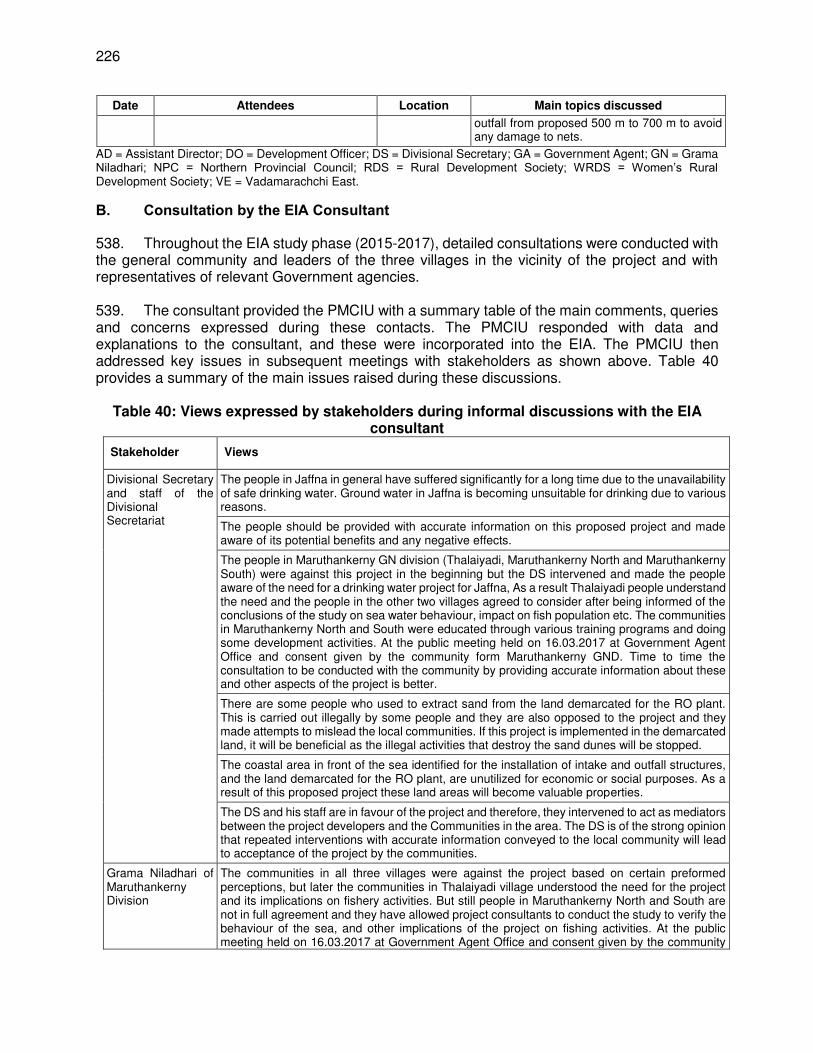
226
Date Attendees Location Main topics discussed
outfall from proposed 500 m to 700 m to avoid any damage to nets.
AD = Assistant Director; DO = Development Officer; DS = Divisional Secretary; GA = Government Agent; GN = Grama Niladhari; NPC = Northern Provincial Council; RDS = Rural Development Society; WRDS = Women’s Rural Development Society; VE = Vadamarachchi East. B. Consultation by the EIA Consultant
538. Throughout the EIA study phase (2015-2017), detailed consultations were conducted with the general community and leaders of the three villages in the vicinity of the project and with representatives of relevant Government agencies. 539. The consultant provided the PMCIU with a summary table of the main comments, queries and concerns expressed during these contacts. The PMCIU responded with data and explanations to the consultant, and these were incorporated into the EIA. The PMCIU then addressed key issues in subsequent meetings with stakeholders as shown above. Table 40 provides a summary of the main issues raised during these discussions.
Table 40: Views expressed by stakeholders during informal discussions with the EIA consultant
Stakeholder Views
Divisional Secretary and staff of the Divisional Secretariat
The people in Jaffna in general have suffered significantly for a long time due to the unavailability of safe drinking water. Ground water in Jaffna is becoming unsuitable for drinking due to various reasons.
The people should be provided with accurate information on this proposed project and made aware of its potential benefits and any negative effects.
The people in Maruthankerny GN division (Thalaiyadi, Maruthankerny North and Maruthankerny South) were against this project in the beginning but the DS intervened and made the people aware of the need for a drinking water project for Jaffna, As a result Thalaiyadi people understand the need and the people in the other two villages agreed to consider after being informed of the conclusions of the study on sea water behaviour, impact on fish population etc. The communities in Maruthankerny North and South were educated through various training programs and doing some development activities. At the public meeting held on 16.03.2017 at Government Agent Office and consent given by the community form Maruthankerny GND. Time to time the consultation to be conducted with the community by providing accurate information about these and other aspects of the project is better.
There are some people who used to extract sand from the land demarcated for the RO plant. This is carried out illegally by some people and they are also opposed to the project and they made attempts to mislead the local communities. If this project is implemented in the demarcated land, it will be beneficial as the illegal activities that destroy the sand dunes will be stopped.
The coastal area in front of the sea identified for the installation of intake and outfall structures, and the land demarcated for the RO plant, are unutilized for economic or social purposes. As a result of this proposed project these land areas will become valuable properties.
The DS and his staff are in favour of the project and therefore, they intervened to act as mediators between the project developers and the Communities in the area. The DS is of the strong opinion that repeated interventions with accurate information conveyed to the local community will lead to acceptance of the project by the communities.
Grama Niladhari of Maruthankerny Division
The communities in all three villages were against the project based on certain preformed perceptions, but later the communities in Thalaiyadi village understood the need for the project and its implications on fishery activities. But still people in Maruthankerny North and South are not in full agreement and they have allowed project consultants to conduct the study to verify the behaviour of the sea, and other implications of the project on fishing activities. At the public meeting held on 16.03.2017 at Government Agent Office and consent given by the community

227
form Maruthankerny GND. Time to time the consultation to be conducted with the community by providing accurate information about these and other aspects of the project is better.
Madel Fishermen A large area along the coastal belt starting from Sundikadu in the south and Point Pedro in the north has been declared by the Fisheries Department as the area suitable for Madel fishing. There were five paadus 02 of them are common and 03 were occupied by private parties involved in Madel fishing before tsunami within the coastal belt identified for this project. All tthese Madel parties have abandoned their activities for more than 2-5 years and they have converted by themselves to fishing in boats.
Other fishermen The two main issues to be clarified for the general fishermen include whether there is any likelihood of a reduction in the fish population in the sea near the outfall and also any threat of the fish population leaving the shallow water to reach for far away areas due to impacts of the proposed project. This group needs accurate information on these two issues.
If the waste diesel and other oils used for the project is released to the sea there can be some negative implications on fishery resources.
Intake structure may disturb fishing nets. We as fishermen need to know the exact location of the area used for installation of intake. We suggest installing an indicator (signal light) for easy identification of the intake even from faraway places in sea.
The fishing communities are also of the opinion that the sea area affected by the project may increase with future expansion of the project. They also think that a larger area of the sea may be declared as a high security zone and prohibited for the use of fishing communities in their boats.
Community members in Thalaiyadi village
The community leaders in this village explained that they are the people who are in close proximity to the proposed project land and sea area. They were against the project in the beginning, but they are now aware of the details and therefore they now welcome the project that will address the most critical problem in their area as well as in the entire Jaffna peninsula. Even though they have positive views of the project they too need answers to few grey areas including: the cost for obtaining sea water that has been purified at high cost, and the quality of the sea water and its suitability for drinking purposes. These issues need to be clarified based on scientific evidence. The infrastructure facilities in the village are in very poor condition. The main road between Soranpattu/Thalaiyadi is dilapidated and other interior roads are also in very poor physical condition. The village is also poor in facilities for schooling; hospitals etc. and therefore they are very keen to use the proposed project as an opportunity/vehicle to improve these facilities. Thalaiyadi people are very happy because of the number of development activities and the Maruthankerny – point Pedro road development works carrying on.
People in Maruthankerny North and South
The wastewater released to the sea from the outfall may lead to reductions in the fish population in the area. If the studies conducted for the project generate scientific evidence proving that there will be no harmful effects on the fish population, we will express our support for the project. The studies were presented and the continuous discussion had with the people through various training program under TA 7676. They participated actively and gained the information satisfactorily.
Our villages are neglected by the government and NGOs in providing improved infrastructure facilities and therefore we are not happy for this type of project to be established in our area. After developed the Maruthankerny Integrated Development Project implementation (Road, basic infrastructure) they are happy.
The proposed project should prioritise providing drinking water facilities to our area too.
540. The main issues arising from this consultation exercise are as follows:
(i) Initially all three of the local communities were opposed to the project, because of concerns that it would reduce fish stocks and restrict their access to local fishing areas, thus affecting their livelihoods;
(ii) People of Thalaiyadi village have subsequently been given detailed information by the DS and PMCIU and are now in favour of the project, on the understanding that their village will be provided with piped drinking water by the scheme;

228
(iii) Maruthankerny North and South remain opposed because of fears of adverse effects on fish stocks;
(iv) During these consultations and those held by the PMCIU, all three villages complained that this area has received insufficient government investment, with the result that public infrastructure (roads, schools, healthcare, etc.) is dilapidated and inadequate.
541. Many of these concerns are based on misconceptions regarding the risks of the project, and a lack of knowledge regarding the range of benefits it will bring. Local support is vital for the successful implementation of this nationally-important infrastructure, so these issues should be addressed in further stakeholder engagement in the near future (see below). Amongst other things this should:
(i) Provide clear evidence from the EIA study that there is unlikely to be any decline in fish stocks as a result of the project, and that this will be confirmed by fisheries monitoring throughout the operational period;
(ii) Inform local fishermen that during construction and operation of the intake and outfall they will only be prohibited from entering a relatively small area, which will be clearly marked with buoys and lights, so there should be little risk of nets becoming entangled on the marine structures;
(iii) Inform fishermen of the range of measures that will be implemented to prevent pollution during construction and operation, and explain why the plant is unlikely to expand in the future;
(iv) Confirm to all three villages that they will be supplied by the project with high quality piped drinking water, at the standard nationwide tariff;
(v) Discuss the other benefits the scheme will bring, including opportunities for short and long-term employment, and sourcing of services (catering, cleaning, etc.) from local businesses where available;
(vi) Also discuss the infrastructure investments agreed by the Northern Provincial Council (renovation of internal roads and playground; new multipurpose public hall) and the planned improvements by this project (upgrading 2 km of road near the site; building a new road alongside the transmission line; etc.).
C. Future Consultation and Disclosure
542. NWSDB will continue the stakeholder communication and engagement process throughout the design, construction, commissioning and operational phases of the project, in order to establish a foundation of mutual trust and provide a forum for the exchange of information, through which any issues can be raised with the project team and addressed by agreed action where necessary. This will involve the same kinds of contacts as employed to date, with some modifications, as follows:
(i) Regular public meetings will be the main forum through which the local community will be informed about the progress of the project and any elements that may affect them (such as temporary restrictions in access during the construction period, the timing of deliveries of large equipment items, etc.). These meetings will be held quarterly or biannually according to need, and the programme will be agreed in advance and published on local government noticeboards and in the local press.
(ii) The next of these meetings is planned for November 2016, when the PMCIUU and their consultants will present and discuss the results of the EIA study, and the PMCIU will address the other issues noted above in order to correct current misconceptions about the project and allow the local community to raise any other concerns.

229
(iii) Smaller meetings will be held on an ad hoc basis with institutional stakeholders, including local and national government officials in the Jaffna area, and those in Colombo where necessary. These will capture a broader range of stakeholders than the meetings held to date, and will include CEA, CCD, MEPA for example. The aim will be to inform all relevant agencies of project progress and allow discussion and resolution of any specific issues as they may arise.
(iv) Focus group sessions will again be held with the local community when needed, to discuss and organise specific activities (such as waste transportation programmes, access arrangements, etc.) and to deal with any issues that can be handled in this way.
543. NWSDB will also comply fully with the disclosure requirements of national law and the ADB SPS and will make the draft final report of the EIA study (this document) available for review by the local community and other stakeholders, in the study area, at the PMCIU office in Jaffna, and in the NWSDB head office in Colombo. They will also make the document available for public inspection as required by the National Environmental Act and other necessary permit applications as discussed in Section 2.B above. NWSDB will make the final EIA report available to a wider audience by uploading a copy onto the NWSDB website, and providing an electronic copy to ADB for their website. Any subsequent updates of the EIA report, and the regular monitoring reports produced throughout the construction stage, will also be disseminated in the same way.
VIII. GRIEVANCE REDRESS MECHANISM
A. Key Principles and Practice
543. The ADB SPS requires the borrower to establish a mechanism to receive and enable resolution of any concerns, complaints and grievances that affected people may have about the project’s environmental or social performance. The Grievance Redress Mechanism (GRM) should be of a scale that is appropriate to the risks and potential adverse impacts of the project. It should also address concerns and complaints promptly, using a process that is easy to understand, transparent, gender responsive, culturally appropriate, and readily accessible to all sectors of the affected community, at no cost and without any retribution. The GRM should not impede access to potential remedies through the country’s judicial or administrative systems; and the project proponent must ensure that affected people are fully and appropriately informed about the mechanism and what they have to do to register any concern or complaint. 544. Experience of development projects suggests that many of the most effective GRMs are those that involve a simple process, which operates within the framework of existing complaints/communication structures, if these are well known and utilised by the affected community. In addition it has often proven useful to have a single point of contact - a nominated liaison officer or focal point, who is able to receive and register complaints or grievances, to assess their relevance and gravity, and to determine the appropriate form of action. Many issues can be solved quickly and effectively by local action on site, but some may need to be considered in more detail. The focal point should have the authority within the project to take simple action locally to resolve a complaint where appropriate, and should have the knowledge and experience to refer a complaint to a higher authority when necessary. 545. The higher authority is the Grievance Redress Committee (GRC), which is a body that meets when necessary to consider more complex and serious complaints that cannot be addressed by straightforward action on site. There is no standard composition for a GRC, but those that have functioned well have generally had the following key officers: (i) a chairperson

230
who is known to and respected by the affected community; (ii) an administrator who is able to transcribe verbal or written complaints quickly, accurately and succinctly, and to keep well-ordered records of committee discussions and to convey decisions and their rationale to complainants in a professional and timely manner; (iii) a senior representative of the client body (PMCIU in this case); (iv) a senior representative of the construction contractor or operator as appropriate (normally the site manager); and (v) a senior representative of the affected community (normally a community Leader). The committee may also co-opt additional technical or legal specialists to provide advice on specific matters when necessary. B. Project GRM and GRC
546. Grievances of concern persons/ affected persons will first be brought to the attention of the PMCIU within 3 days after receiving the complaint of the affected persons. Grievances not redressed by the PMCIU within 7 days will be brought to the notice of Project Director. Grievances not addressed at Project Director level within 5 days will be brought to the Divisional Secretariat level Grievance Redress Committee. There is a long history of grievance redress at the DS level services through the Divisional Secretary. This is a well-established procedure. The community members in DS area present their grievances to the DS offices where arrangements have been made to inspect the problems of the community members and help to solve the problems in the field itself, if possible or otherwise take actions to forward the grievances of the communities that cannot be solved to the higher authorities of the District. This practice of resolution of grievances through the GRC will be formalized for this project. The GRC will comprise of the Divisional secretary of the Vadamarachchi as chair, a representative from the NWSDB, the PMIU Sociologist and a resident from the Maruthankerny Grama Niladhari division. The PMCIU Sociologist will observe and take minutes. Environmental related grievances will be coordinated by Environment Officer of PCMIU or Environmental Specialist. 547. The GRC will meet when grievances are put forward by the Project Director to determine the merit of each grievance, and resolve grievances within a month of receiving the complaint. Grievances which cannot be resolved at this level within 7 days will be referred by affected persons to the higher level at the District. If the GRM solution proposed at the district level is not acceptable to the complainant, he/she can take the matter to legal channels. This however, does not prohibit them from seeking legal recourse of action during any stage of the process. Diagram 1 describes the steps of the GRM process. 548. Records will be kept of all grievances received including, contact details of complainant, date that the complaint was received, nature of grievance, agreed corrective actions and the date these were resolved and outcome. A project information sheet including brief description of the sub-project, likelihood negative impacts, institutions to be contacted during construction phase and their locations will be provided to the project related stakeholders. This information will be shared among representatives of key stakeholders in and outside of the project area at least one month prior to commencement of the construction work. It is noted that most of the stakeholders in the project area already know about the proposed project. 549. A form will be used to register the complaints of the project affected communities in project implementing area. The copies of the form will be made available with the site engineers of the contractors, construction supervision engineers attached to the site and the PMCIU sociologist. The registered complaints using this form will be received by the Sociologist (PMCIU) who will take necessary actions to provide timely solutions.

231
550. During the project preparation information about the project and likelihood of impacts have been conveyed to the community leaders and other key stakeholders. A detailed leaflet with specific details about the sub-project and GRM arrangements will be distributed to the affected community members prior to commencement of civil work. The PMCIU sociologist together with other staff will conduct awareness meetings with the communities and the construction crew to explain about the GRM arrangements to be followed. 551. The PMIU sociologist will play a key role in monitoring of project sites during construction period. The construction crew will also be made aware about the GRM mechanism by the PMIU. They will be responsible to monitor the social safeguards related activities at the project sites during implementation period. The information on the environmental and social safeguard implementation will be included in semi-annual monitoring reports submitted to the ADB. Appendix R provides specimen form that can be used for grievance registration. 552. The focal point for receiving complaints /queries will be sociologist of PMCIU office who is responsible for taking actions to solve the problems with the help of concerned parties. The PMIU sociologist together with other staff in PMCIU will make frequent visits to the project sites to ascertain if there are any issues. The communities can also contact the PMCIU sociologist through a notified telephone number and lodge their complaints. They also can post letters with their complaints to the PMIU office at its address mentioned below. The communities in the project area can also meet the PMIU sociologist at the PMCIU office. The communities in the project area can also reach the site office established in the project area during construction period and make their complaints/grievances to the staff in the construction site. These grievances will be collected by the PMIU sociologist to offer solutions through the institutional process established. The multi-layered grievance redress approach is shown below:

232
553. With guidance from ADB, the project established a GRM and GRC in November 2015, which encompasses several elements of the good practice noted above. The aim is to resolve grievances and disputes at local level during project implementation, and to create trust and confidence amongst community members that the committee and the project will support them if there is any adverse impact upon their livelihood or environment that is caused by the project. 554. Most adults in the three local villages are members of the local Rural Development Society (RDS), which are community organisations that are generally stronger in the north of Sri Lanka than elsewhere in the country. In the project area RDS hold regular meetings at which participation is high and discussions cover social issues as well as physical and development needs. Monthly meetings are attended by the respective Grama Niladhari155 (GN), which enables resolution of some social and resource management problems; and any that cannot be resolved are forwarded to the Divisional Secretary (DS), who maintains an active involvement in village issues through this mechanism. The RDS and Women’s RDS (WRDS) are an essential institutional mechanism for local people to seek and obtain assistance in solving village-level problems, and the project GRM will operate within this framework. 555. The GRC is chaired by the DS of Vadamarachchi East; the GRC Coordinator is the Development Officer of Vadamarachchi East; and the GRC Secretary is the Sociologist of the JKWSP PMCIU. The other members of the GRC are: the Grama Niladhari; Secretary of Thalaiyadi Fisheries Society; President and one other member of Thalaiyadi RDC; two members of Thalaiyadi WRDC; the Coordinating Officer of the JKWSP PMCIU; and two other community members. 556. The stated ethos of the GRC is to be transparent, objective and unbiased in addressing any issues or grievances related to environmental or social safeguards in respect of the community who live in the vicinity of the project site and/or depend on the adjacent sea area. The operations of the GRC include the following:
(i) Keeping a feedback register and receiving RODP-related complaints, comments or suggestions from the community and other relevant stakeholders;
(ii) Reviewing the feedback and taking appropriate action(s) as soon as possible; (iii) Seeking to resolve issues quickly, amicably and transparently in order to avoid
adverse social and environmental impacts and maintain good community relations, and facilitate project progress and ultimate completion.
557. The GRC may wish to consider incorporating a senior representative of the project contractor once tendering is completed, and to include representatives of the two other local villages in due course. 558. ADB Accountability Mechanism. People who are, or may in the future be, adversely affected by the project may submit complaints to ADB’s Accountability Mechanism.156 The Accountability Mechanism provides an independent forum and process whereby people adversely affected by ADB-assisted projects can voice, and seek a resolution of their problems, as well as report alleged violations of ADB’s operational policies and procedures. Before submitting a complaint to the Accountability Mechanism, affected people should make an effort in good faith to solve their problems by working with the concerned ADB operations
155 Grama Niladhari (“village officer”) is a public official appointed by central government to carry out administrative
duties in a Grama Niladhari division, which is a subunit of a Divisional Secretariat. Duties include issuing permits, gathering statistics, maintaining the voter registry and keeping the peace by settling local disputes
156 ADB Accountability Mechanism. http://www.adb.org/Accountability-Mechanism/default.asp

233
department. Only after doing that, and if they are still dissatisfied, should they approach the Accountability Mechanism.
IX. ENVIRONMENTAL MANAGEMENT PLAN
559. An Environmental Management Plan (EMP) is the document through which the mitigation proposed in the environmental assessment is planned and subsequently implemented. The present document is the Employer’s (NWSDB) EIA report, and this chapter provides the Employer’s EMP, which sets out the mitigation that the DBO contractor is required to provide during project design, construction and operation, and the manner in which the client requires the mitigation to be provided. The EIA is included in the DBO contract, so by accepting the contract, the chosen contractor is legally obliged to implement all specified mitigation. The contractor then produces their own EMP before beginning each of the site activity stages (construction and operation), which provides their interpretation of the mitigation requirements, with detailed descriptions of how they propose to implement each measure (and any other environmental protection), with a rationale for any deviations from the client’s EMP. 560. According to the ADB SPS, an Environmental Management Plan (EMP) should identify and summarise all anticipated significantly adverse environmental impacts and risks, and describe the mitigation and any proposed environmental monitoring, with appropriate technical details. It also describes the arrangements for implementing the EMP, including phasing, responsibility for implementing the mitigation and monitoring, the associated institutional arrangements, and the cost of implementing the EMP. This chapter covers these and other aspects of the EMP. 561. The purpose of the environmental management plan (EMP) is to ensure that the activities are undertaken in a responsible, non-detrimental manner with the objectives of: (i) providing a proactive, feasible, and practical working tool to enable the measurement and monitoring of environmental performance on-site; (ii) guiding and controlling the implementation of findings and recommendations of the environmental assessment conducted for the project; (iii) detailing specific actions deemed necessary to assist in mitigating the environmental impact of the project; and (iv) ensuring that safety recommendations are complied with. 562. A copy of the EMP must be kept on work sites at all times and at operator’s office during O&M phase. This EMP will be included in the bid documents and will be further reviewed and updated during design and implementation. The EMP will be made binding on all contractors operating on the site and will be included in the contractual clauses. Non-compliance with, or any deviation from, the conditions set out in this document constitutes a failure in compliance. 563. The contractor will be required to (i) establish an operational system for managing environmental impacts (ii) carry out all of the monitoring and mitigation measures set forth in the EMP; and (iii) implement any corrective or preventative actions set out in safeguards monitoring reports that PCMIU will prepare from time to time to monitor implementation of this EIA and EMP. The contractor shall allocate a budget for compliance with these EMP measures, requirements and actions. A. Responsibilities for EMP Implementation
The following agencies will be responsible for EMP Implementation: (i) NWSDB is the Executing Agency (EA) responsible for overall management,
coordination, and execution of all activities funded under the loan;

234
(ii) PCMIU is the Implementing Agency (IA) responsible for coordinating procurement and construction of the project. BUIDCO through its Project Management Unit (PMU) at Patna will be implementing the project;
(iii) The Project Management Consultant (PMC) assists in managing the project including procurement and assures technical quality of design and construction and also acts as monitor of works and operations of all contractors under JKWSP;
(iv) The contractor for RODP Project will be responsible for final design, execution of all construction works, and operation and maintenance. The contractor will work under the guidance of the PCMIU. The environmental related mitigation measures will also be implemented by the contractor.
564. The contractor’s conformity with contract procedures and specifications during construction will be carefully monitored by the PCMIU. The contractor is required to: Designate a full time environment specialist (with expertise in coastal/marine works) who will: (i) update this draft EIA and update/develop EMP as per detailed design; (ii) implementing EMP including confirmatory and establish baseline data, during and post-construction, and during O&M; (iii) conducting site induction ensuring all personnel are familiar with EMP and relevant safeguards for their work; (iv) establish principle, environmental performance criteria, and indicator157 as per detailed design; (v) ensuring protected, endangered, threatened, or near-threatened ecological communities are not affected; (vi) consulting stakeholders and disseminating information; (vii) addressing grievances on site level; (vii) developing O&M manuals, incorporating all O&M phase EMP measures, and implementing them; (viii) reporting; and ix) implementing corrective action plan/s. 565. Responsibility for updating EIA. Contractor is responsible for updating the EIA during the detailed design to reflect changes in project. All necessary baseline and modelling studies commensurate with the changes in the location and design of the project as appropriate, shall be conducted with the help of specialists. 566. Responsibility for monitoring. During construction, PMC’s Environmental Specialist and the designated representative engineer of the PCMIU will monitor the contractor’s environmental performance. During the operation phase, monitoring will be the responsibility of the operator. PMC will have a responsibility for compliance monitoring as a third party. 567. Responsibility for Reporting. NWDB and PCMIU will submit to ADB quarterly reports on implementation of the EMP. ADB will field annual environmental review missions which will review in detail the environmental aspects of the project. Any major accidents having serious environmental consequences will be reported immediately. PMC will assist the PCMIU in preparing monthly, quarterly, semi-annual and annual progress reports. B. Environmental Management Plan
568. Table 41 to 43 show Environment Management Plans (stage-wise) summarising the potential adverse environmental impacts, proposed mitigation measures, responsible parties, and cost of implementation. This EMP will be included in the bid documents and will be further reviewed and updated during implementation. Table 44 & Table 45 show the proposed 157 As per ADB SPS, when a project occurs in critical habitat, a net gain in biodiversity value is required. ‘Principles’
are interpreted as the fundamental statements about a desired outcome (must be in line with Dolphine Action Plan and (draft) VGDS management plan. ‘Criteria’ are the conditions that need to be met in order to comply with a principle. ‘Indicators’ are the measurable states which allow the assessment of whether or not a particular criterion has been met.

235
Environmental Monitoring Plan (EMoP) for the project. It includes all suggested environmental parameters, description of sampling stations, frequency of monitoring, applicable standards, responsible parties, and estimated cost.

236
Table 41: Pre-construction EMP Table Potential Impact Mitigation Measures Parameter /
indicator of compliance
Monitoring Frequency
Implementation Agency
Monitoring Agency
Estimated cost
Poor environmental management by DBO Contractor
Designate a full time environment specialist (expertize in works in marine habitats) who will be in charge of coordination with P developing EMP as per detailed design. and implementing EMP including conduct of all surveys, monitoring actions etc.,.
Environmental specialist shall be in place from the day of mobilization of DBO contractor (throughout design and construction, and intermittent during operation phase)
Coordinate with the PCMIU on confirmatory surveys to be conducted during the design phase and complete as required with support of external experts
Mobilization of staff with suitable experience and expertize
One-off during mobilization, and continuously throughout the contract period
DBO Contractor PCMIU Part of construction cost
Loss of scrub land, flora, fauna: protected flora species
Conduct a confirmatory survey by an Ecologist to identify and mark, if any, protected plant species (4 plant species reported from surrounding area: Sesuvium portulacastrum, Halosarcia indica, Salicornia brachiate and Citrullus colocynthis) on site and also on the site survey maps.
Protected plants survey map & markings on site
One-off after survey
DBO contractor through a preapproved agency
PCMIU supported by an independent agency (IUCN Sri Lanka)
Lump sum costs: US$ 5,000
Integrate identified protected plants in the layout design of RODP to avoid the need to remove/cut these plants
RODP Layout plan One-off during layout finalization
DBO contractor PCMIU No additional Costs
If unavoidable, translocate protected species in the nearby scrub land; prepare Tree Translocation, Cutting & Replantation Plan If translocation is not possible, and if it is necessary to remove/cut protected plants, prepare a justification to establish that it is not feasible to avoid or translocate plant
Obtain approval of competent authority for cutting/removal and
Tree Translocation, Cutting & Replantation Plan (shall include justification, minimization & approvals)
One-off during layout finalization
DBO contractor through a preapproved agency
PCMIU supported by an independent agency (IUCN)
Lump sum costs: US$ 10,000

237
Potential Impact Mitigation Measures Parameter / indicator of compliance
Monitoring Frequency
Implementation Agency
Monitoring Agency
Estimated cost
plant 5 trees of same species for each tree that is removed
Adopt minimal tree cutting as a general principle in planning & design; minimize tree cutting – either of protected species or otherwise
In general, follow avoidance and compensatory approach for cutting of tree species; plant 2 trees for each tree removed
Develop a 3-5 m green buffer zone around the plant (within the facility or just outside the boundary wall) with local tree species to shield the plant’s visibility, so that the scrub land around the plant is used as in the existing condition without any perceived intrusion by fauna
RODP Layout plan One-off during layout finalization
DBO contractor through a preapproved agency
PCMIU supported by an independent agency (IUCN)
Lump sum costs: US$ 20,000
Plant Operation & maintenance manual shall include clear provisions on protection and conservation of environment & wildlife, including prohibition on cutting of trees, removal of shrubs and bushes, hunting / harming wild animals etc.; do’s and don’ts to be followed by all concerned with RODP
RODP O&M plan One-off during layout finalization
DBO contractor through a preapproved agency
PCMIU supported by an independent agency (IUCN)
No additional costs
Impacts on protected species of avifauna
Conduct field surveys by an ecologist (6 months prior to start of work) to confirm if there are any birds of protected species (painted stork, and spot-billed pelican), and identify if any trees with nests / breeding places:
If there are birds any of these species on trees within the site, but no nests, ensure that the birds are not harmed, and allowed to move away freely
If there are any trees with nests / breeding birds, work shall not
ToR for the survey Confirmation survey output & mitigation measures
One-off prior to survey One-off after survey
DBO contractor through a preapproved agency
PCMIU supported by an independent agency (IUCN)
Lump sum costs: US$ 5,000

238
Potential Impact Mitigation Measures Parameter / indicator of compliance
Monitoring Frequency
Implementation Agency
Monitoring Agency
Estimated cost
commence until nesting cycle is complete and the birds leave the nest
If there are no protected birds or any other protected species, immediately initiate work on boundary fencing; the work related disturbance will ensure the birds move away from the site, and do not prefer the site for further roosting/nesting
Impacts on protected species of fauna
Conduct confirmatory surveys by experts to rule out reptile (salt water crocodile & hawksbill turtle) breeding areas in the proposed project sites and reconfirm that their extent & nature of inhabitation is limited to occasional visits to the beach at maximum
Review the following suggested measures & develop further based on confirmatory survey:
o Scheduling marine works (including beach construction) outside potential visiting season
o Providing workers or posting in public places for the workers, illustrations or pictures of protected, endangered, threatened, and/or near-threatened species, which can be found in the work area or its immediate surroundings.
o Engaging experts to oversee the construction works
o Instructing workers to stop work immediately and report to if any turtles or crocodiles are spotted on the site
o Creating awareness and conducting training; prohibiting killing or harming of any animals by site personnel
Confirmatory survey results & suggested mitigation measures
One-off after survey
DBO contractor through a preapproved agency
PCMIU supported by an independent agency (IUCN)
Lump sum costs: US$ 10,000

239
Potential Impact Mitigation Measures Parameter / indicator of compliance
Monitoring Frequency
Implementation Agency
Monitoring Agency
Estimated cost
Effluent (Brine) disposal
Conduct confirmatory numerical modeling for brine discharge– both near and far-field, covering all 4 seasons (2 monsoon + 2 intermonsoon)
Ensure that proper mixing is achieved to allow rapid dilution within a small area (base configuration: 600 mm diameter offshore disposal, 500 m from shore, pipeline buried under sea bed; discharge point on a sloping sea bed, with 3 diffuser ports of 200 mm dia, projected to 0.5 – 1 m above sea bed, at a spacing of 5 m and arrange 60o, discharge velocity 3.5 – 4.5 m/sec
Minimum dilution level: excess salinity <0.5 ppt within 22 m of discharge point
Numerical modeling output – 4 seasons Final outfall configuration
One-off to review modeling output One off during finalization of outfall configuration
DBO contractor through a preapproved agency
PCMIU Lump sum costs: 20,000 US$
Sludge / solid waste from RODP
Prepare a solid waste and sludge management plan (SW&SMP)
All solid waste streams emanating from the Desalination Plant at their respective points of discharge must comply with: National Environmental (Municipal Solid Waste) Regulations, No. 1 of 2009
Dispose off biodegradable waste by composting, and other waste such as inert by land filling
Spent cartridges and other material from plant shall be returned to the manufacturer or dispose as per their specifications
Hazardous waste shall be stabilized, encapsulated, and disposed off as per internationally accepted practices
SW&SMP Quantity and quality of waste and disposal methods
One-off during the detailed design stage
DBO contractor PCMIU No additional costs
Source water quality – risk of quality degradation
Review the need to create source protection zone (cordon sanitare) to control land based pollution source
Source protection measures
Prior to start of operation
DBO contractor PCMIU No additional costs
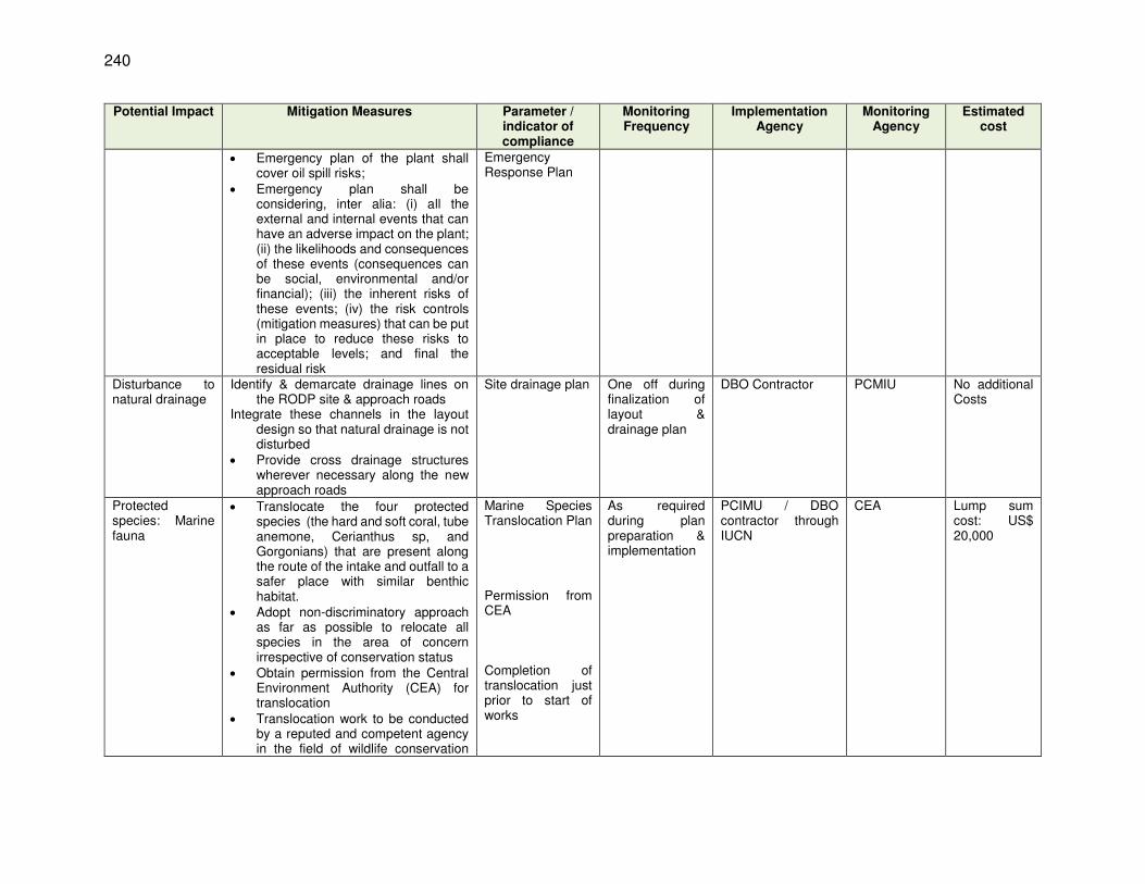
240
Potential Impact Mitigation Measures Parameter / indicator of compliance
Monitoring Frequency
Implementation Agency
Monitoring Agency
Estimated cost
Emergency plan of the plant shall cover oil spill risks;
Emergency plan shall be considering, inter alia: (i) all the external and internal events that can have an adverse impact on the plant; (ii) the likelihoods and consequences of these events (consequences can be social, environmental and/or financial); (iii) the inherent risks of these events; (iv) the risk controls (mitigation measures) that can be put in place to reduce these risks to acceptable levels; and final the residual risk
Emergency Response Plan
Disturbance to natural drainage
Identify & demarcate drainage lines on the RODP site & approach roads
Integrate these channels in the layout design so that natural drainage is not disturbed
Provide cross drainage structures wherever necessary along the new approach roads
Site drainage plan One off during finalization of layout & drainage plan
DBO Contractor PCMIU No additional Costs
Protected species: Marine fauna
Translocate the four protected species (the hard and soft coral, tube anemone, Cerianthus sp, and Gorgonians) that are present along the route of the intake and outfall to a safer place with similar benthic habitat.
Adopt non-discriminatory approach as far as possible to relocate all species in the area of concern irrespective of conservation status
Obtain permission from the Central Environment Authority (CEA) for translocation
Translocation work to be conducted by a reputed and competent agency in the field of wildlife conservation
Marine Species Translocation Plan Permission from CEA Completion of translocation just prior to start of works
As required during plan preparation & implementation
PCIMU / DBO contractor through IUCN
CEA Lump sum cost: US$ 20,000

241
Potential Impact Mitigation Measures Parameter / indicator of compliance
Monitoring Frequency
Implementation Agency
Monitoring Agency
Estimated cost
with previous marine translocation experience in Sri Lanka
Translocation should be done immediately before the marine trenching work begins, and it should cover 50 m strip along the pipelines alignment and 50 m around intake and outfall
Impacts on protected species of flora and fauna
Completion of Translocation of rare plants/trees prior to start of construction
Completion of confirmatory surveys & integration of mitigation measures in design & implementation
Create awareness and conduct training; prohibit any killing or harming of animals by site personnel
Completion of activities
One-off prior to start of construction
DBO contractor through a reputed and preapproved agency
PCMIU supported by an independent agency (IUCN)
No additional costs
Work program & plans
Finalize construction program duly considering EMP provisions on work schedule
Work schedule One-off prior to start of construction
DBO contractor PCMIU No additional costs
Following plans be developed for implementation
o Construction Waste Management Plan
o Transportation Plan for construction material, equipment and waste
o Health & Safety Plan o Construction Camp Development
& Management Plan o Spill Control and Containment
Plan o Marine & Beach Area
Construction Work Plan o Erosion control plan near the
lagoon for pipeline works
Respective plans One-off prior to start of construction
DBO contractor PCMIU No additional costs
Consents, permits, clearances, no objection
Obtain all necessary consents, permits, clearance, NOCs, prior to start of civil works (PAA/CEA; EPL; permits from CCD, MEPA etc.)
Clearances and approvals
One-off prior to start of construction
PCMIU
NWDB Report to ADB via EMRs
No additional costs

242
Potential Impact Mitigation Measures Parameter / indicator of compliance
Monitoring Frequency
Implementation Agency
Monitoring Agency
Estimated cost
certificate (NOC), etc.
Include in project implementation all conditions and provisions where necessary
Integration in designs
One-off during design & prior to start of construction
DBO Contractor PCMIU No additional costs
Utilities Identify and include locations and operators of these utilities in the detailed design to prevent unnecessary disruption of services during the construction phase.
Prepare a contingency plan to include actions to be done in case of unintentional interruption of services.
Identify the list of affected utilities and operators and coordinate closely with relevant government departments.
If relocations are necessary, coordinate with the providers to relocate the utility.
Maps showing utilities & likely disruptions Emergency plans in case of any likely disruption
One-off during design & prior to start of construction
DBO Contractor PCMIU No additional costs
Sites for construction work camps, areas for stockpile, storage and disposal
Except disposal sites, all the work sites (camps, storage, stockpiles etc.) will be located within the selected RODP site.
No construction camp shall be located on the beach from sea to up to Mamune road
For conveyance pipeline works, material shall be brought to site as and when required, and temporary storage of material (pipe, sand etc.,) shall be made near the work site along the road itself within the RoW.
No temporary storage shall be located at Vadamarachchi lagoon section
Waste shall be disposed in existing approved disposal sites; any new sites shall be developed considering siting guidelines, maintained and operated accordingly
List of pre-approved sites for construction work camps, areas for stockpile, storage and disposal Waste management plan
One-off prior to start of construction
DBO Contractor PCMIU No additional costs
Sources of construction materials
Obtain construction materials for this project from the existing quarries permitted / licensed by government
Permits issued to quarries/sources of materials
One-off prior to start of work
DBO Contractor PCMIU No additional costs
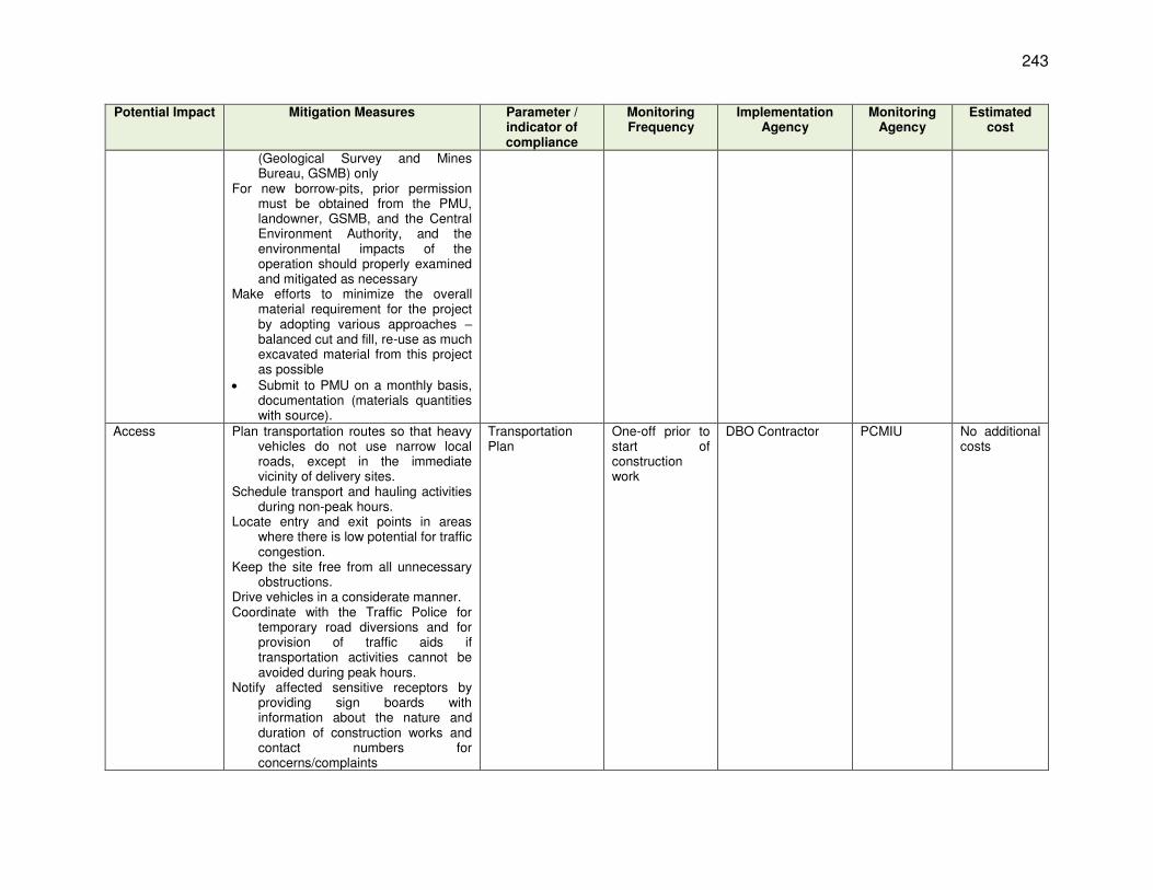
243
Potential Impact Mitigation Measures Parameter / indicator of compliance
Monitoring Frequency
Implementation Agency
Monitoring Agency
Estimated cost
(Geological Survey and Mines Bureau, GSMB) only
For new borrow-pits, prior permission must be obtained from the PMU, landowner, GSMB, and the Central Environment Authority, and the environmental impacts of the operation should properly examined and mitigated as necessary
Make efforts to minimize the overall material requirement for the project by adopting various approaches – balanced cut and fill, re-use as much excavated material from this project as possible
Submit to PMU on a monthly basis, documentation (materials quantities with source).
Access Plan transportation routes so that heavy vehicles do not use narrow local roads, except in the immediate vicinity of delivery sites.
Schedule transport and hauling activities during non-peak hours.
Locate entry and exit points in areas where there is low potential for traffic congestion.
Keep the site free from all unnecessary obstructions.
Drive vehicles in a considerate manner. Coordinate with the Traffic Police for
temporary road diversions and for provision of traffic aids if transportation activities cannot be avoided during peak hours.
Notify affected sensitive receptors by providing sign boards with information about the nature and duration of construction works and contact numbers for concerns/complaints
Transportation Plan
One-off prior to start of construction work
DBO Contractor PCMIU No additional costs

244
Potential Impact Mitigation Measures Parameter / indicator of compliance
Monitoring Frequency
Implementation Agency
Monitoring Agency
Estimated cost
Road works and road signage must be illuminated at night.
Ensure access to households along the alignment of conveyance main during the construction phase.
Access on beach/sea front to fishing community and disruption of surrounding fishing activity during ffd2
Prepare Marine & Beach Area Construction Work Plan & Method Statement; include the following:
o Plan all beach works such that there is no or minimal disturbance to movement of fishermen, boat landing sites etc.;
o Avoid marine works during peak fishing season (June to September)
o demarcate the work area, and if there any existing lines of movement within that beach front, ensure alternative approach is available; coordinate with PMU to consult with local community to plan works
o Limit the size of the construction area on the beach and there shall be no encroachment to outside the specified areas;
o Access should not be closed completely, provide alternative way for fishermen to approach to their work places (e.g. boat landing sites); leave mounds of soil in between or provide wooden planks or metal sheets with proper barricading to allow temporary access
o limit the spread of suspended sediment by conducting marine trenching works in calmer dry season conditions, and stopping work if the spread of sediment in the water becomes excessive as per the guideline below
o The turbidity of the water is to be measured (ISO 7027) at the edge of
Marine & Beach Area Construction Work Plan & method statement
One-off prior to start of construction work
DBO Contractor PCMIU No additional costs

245
Potential Impact Mitigation Measures Parameter / indicator of compliance
Monitoring Frequency
Implementation Agency
Monitoring Agency
Estimated cost
the construction zone158 during trenching and backfilling activities; when the turbidity exceeds the minimum of the background turbidity plus 20% or 100 NTU, the trenching is to cease until the turbidity returns to the background level plus 10%.
o Construction noise to comply with International Finance Corporation (IFC) Environmental Health and Safety (EHS) Guidelines Table 1.7.1 and these will be monitored for compliance with these guidelines
o boundary of the work site). o It will also be important for the
contractor to enforce high standards of behavior amongst the workforce both on and off site, and to maintain clean, tidy and highly professional worksites, to ensure that all persons who come into contact with the construction gain a positive impression of the conduct of the project.
If there is any disruption to fishing activity, compensation to be provided as per the resettlement plan of the project
158 The construction zone has been set as follows: A construction exclusion zone marked by buoys must be established during the Design-Build period for these
works. The zone must clear all works by 50 meters.

246
Table 42: Construction EMP Table Potential Impact
Mitigation Measures Parameter /
Indicator of
compliance
Monitoring Frequency
Implementing
Agency
Monitoring Agenc
y
Estimated cost
Air quality impacts: Site works
As far as possible, plan site clearance and earthwork activities towards the end of the north-east monsoon (January - February), when the soils will be damp naturally, without being subject to the downpours of the previous two months.
To suppress dust, Contractor should water exposed sand, soil and stockpiled material on site sufficiently frequently (several times per day)
Provide a compound wall or wind breaking structure around the plant site to minimize the wind; this will minimize dust generation, and also drifting of sand into excavated trenches
If dust generation is significant, provide a dust screen of appropriate height Workers and staff should be provided with dust masks & instructed to use them on site Conduct work in stages to reduce dust impacts; clearing and then conducting construction
in only a portion of the site at a time. Retention of vegetation is the most natural and effective way of protecting soil from erosion
by wind and rain; the feasibility of phasing site clearance in this way in order to reduce these impacts should be investigated when the construction work is planned in detail by the DBO Contractor.
Control access to work area, prevent unnecessary movement of vehicles, workers, public trespassing into work areas; limiting soil disturbance will minimize dust generation
Contractor’s environmental manager should monitor these activities and take action to apply the mitigation if dust production becomes significant.
Schedule of works Dust suppression measures - Visual site observations Ambient air quality monitoring as per EMP
Weekly
DBO contractor
PCMIU
Part of construction cost
Air quality impacts: material haulage, vehicle and equipment use
Use tarpaulins to cover loose material (soil, sand, aggregate) when transported by trucks Clean wheels and undercarriage of haul trucks prior to leaving construction site/quarry Control dust generation while unloading the loose material (particularly aggregate, soil) at
the site by sprinkling water and unloading inside the barricaded area Stabilize surface soils where loaders, support equipment and vehicles will operate by using
water and maintain surface soils in a stabilized condition Ensure that all the construction equipment, machinery are fitted with pollution control
devises, which are operating correctly, Ensure that only those vehicles and equipment in good condition, and are in good
maintenance are used for project construction Vehicles / equipment should have a valid Vehicle Emission Certificate (VEC) showcasing
emissions below the specified limits Maintain VEC records of all vehicles all times for ready inspection at the work sites
Transportation Plan Dust suppression measures - Visual site observations Ambient air quality monitorin
Weekly
DBO contractor
PCMIU
Part of construction cost
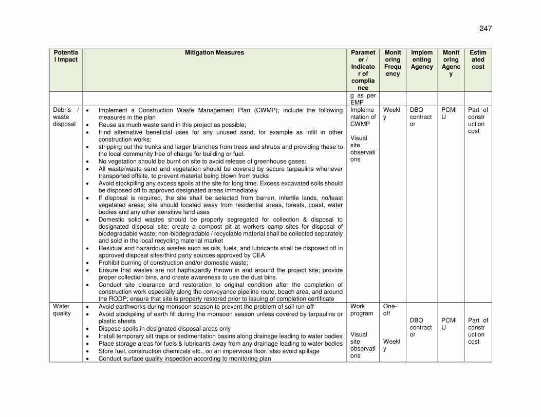
247
Potential Impact
Mitigation Measures Parameter /
Indicator of
compliance
Monitoring Frequency
Implementing
Agency
Monitoring Agenc
y
Estimated cost
g as per EMP
Debris / waste disposal
Implement a Construction Waste Management Plan (CWMP); include the following measures in the plan
Reuse as much waste sand in this project as possible; Find alternative beneficial uses for any unused sand, for example as infill in other
construction works; stripping out the trunks and larger branches from trees and shrubs and providing these to
the local community free of charge for building or fuel. No vegetation should be burnt on site to avoid release of greenhouse gases; All waste/waste sand and vegetation should be covered by secure tarpaulins whenever
transported offsite, to prevent material being blown from trucks Avoid stockpiling any excess spoils at the site for long time. Excess excavated soils should
be disposed off to approved designated areas immediately If disposal is required, the site shall be selected from barren, infertile lands, no/least
vegetated areas; site should located away from residential areas, forests, coast, water bodies and any other sensitive land uses
Domestic solid wastes should be properly segregated for collection & disposal to designated disposal site; create a compost pit at workers camp sites for disposal of biodegradable waste; non-biodegradable / recyclable material shall be collected separately and sold in the local recycling material market
Residual and hazardous wastes such as oils, fuels, and lubricants shall be disposed off in approved disposal sites/third party sources approved by CEA
Prohibit burning of construction and/or domestic waste; Ensure that wastes are not haphazardly thrown in and around the project site; provide
proper collection bins, and create awareness to use the dust bins. Conduct site clearance and restoration to original condition after the completion of
construction work especially along the conveyance pipeline route, beach area, and around the RODP; ensure that site is properly restored prior to issuing of completion certificate
Implementation of CWMP Visual site observations
Weekly
DBO contractor
PCMIU
Part of construction cost
Water quality
Avoid earthworks during monsoon season to prevent the problem of soil run-off Avoid stockpiling of earth fill during the monsoon season unless covered by tarpaulins or
plastic sheets Dispose spoils in designated disposal areas only Install temporary silt traps or sedimentation basins along drainage leading to water bodies Place storage areas for fuels & lubricants away from any drainage leading to water bodies Store fuel, construction chemicals etc., on an impervious floor, also avoid spillage Conduct surface quality inspection according to monitoring plan
Work program Visual site observations
One-off Weekly
DBO contractor
PCMIU
Part of construction cost

248
Potential Impact
Mitigation Measures Parameter /
Indicator of
compliance
Monitoring Frequency
Implementing
Agency
Monitoring Agenc
y
Estimated cost
Pump out the water collected in the pits / excavations to a temporary sedimentation basin dispose off only clarified water into drainage channels/streams
Consider safety aspects related to trench /pit collapse due to accumulation of water Conduct water quality monitoring as per EMP
Vadamarachchi lagoon water quality
Prepare a method statement following internationally accepted construction procedures in wetlands. This interalia include pollution control (water, air, noise), limiting disturbance, unharming wildlife etc.,
Schedule works during low water level in the lagoon; no works be scheduled during September to March (migratory season for birds)
Lower the precast pipe slowly to allow any aquatic organism below it to move away; also avoid any unnecessary disturbance to the still water
Water, slurry (silt / sand mixed with water) collected in the lowered pipe shall not be pumped/disposed back directly into the lagoon; this should be pumped to a temporary sedimentation basin or tank; after proper settling in the basin, clarified water can be let into lagoon by surface discharge (not to be pumped directly into the lagoon; collected sand and silt be utilized in the construction and shall not be disposed off in the lagoon
No spillage of oil, grease, chemicals etc., into the lagoon Dispose any residuals at identified disposal site Stock pile construction material away from the lagoon area Develop a Concrete Spill Prevention and Containment Plan, educate workers about the
plan, and have the necessary materials on site prior to and during construction Enure that no equipment/material /workers, except the precast pipe that is lowered into
water, comes in contact with water; this should strictly be prevented Do not conduct any cleaning, washing, rinsing of concrete or other equipment near the
lagoon; prevent any waste / water from discharging into the lagoon. Refuel equipment within the designated refueling containment area away from the lagoon Inspect all vehicles daily for fluid leaks before leaving the vehicle staging area, and repair
any leaks before the vehicle resumes operation Ensure that no silt laden runoff from nearby construction area (pipeline construction sites)
enter the lagoon; this can be avoided by scheduling the construction work around the lagoon area in non-monsoon; to accommodate for untimely rains, contractor should provide silt traps as required
Excess water sprinkling on soil, material to control dust may also generate runoff which may enter the lagoon; this should be avoided by controlled water sprinkling
Conduct water quality monitoring as per EMP
Work program Visual site observations Water quality monitoring data
One-off Weekly
DBO contractor
PCMIU
Part of construction cost
Pollution from
Ensure that batching plant is installed with in-built air pollution and dust control system; for fugitive emissions /dust from loading area, provide dust screen around the components
Establishment of
One-off
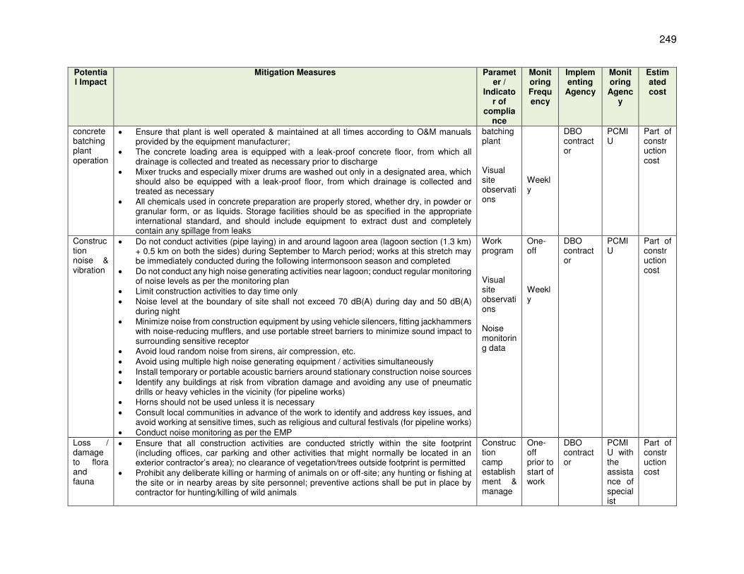
249
Potential Impact
Mitigation Measures Parameter /
Indicator of
compliance
Monitoring Frequency
Implementing
Agency
Monitoring Agenc
y
Estimated cost
concrete batching plant operation
Ensure that plant is well operated & maintained at all times according to O&M manuals provided by the equipment manufacturer;
The concrete loading area is equipped with a leak-proof concrete floor, from which all drainage is collected and treated as necessary prior to discharge
Mixer trucks and especially mixer drums are washed out only in a designated area, which should also be equipped with a leak-proof floor, from which drainage is collected and treated as necessary
All chemicals used in concrete preparation are properly stored, whether dry, in powder or granular form, or as liquids. Storage facilities should be as specified in the appropriate international standard, and should include equipment to extract dust and completely contain any spillage from leaks
batching plant Visual site observations
Weekly
DBO contractor
PCMIU
Part of construction cost
Construction noise & vibration
Do not conduct activities (pipe laying) in and around lagoon area (lagoon section (1.3 km) + 0.5 km on both the sides) during September to March period; works at this stretch may be immediately conducted during the following intermonsoon season and completed
Do not conduct any high noise generating activities near lagoon; conduct regular monitoring of noise levels as per the monitoring plan
Limit construction activities to day time only Noise level at the boundary of site shall not exceed 70 dB(A) during day and 50 dB(A)
during night Minimize noise from construction equipment by using vehicle silencers, fitting jackhammers
with noise-reducing mufflers, and use portable street barriers to minimize sound impact to surrounding sensitive receptor
Avoid loud random noise from sirens, air compression, etc. Avoid using multiple high noise generating equipment / activities simultaneously Install temporary or portable acoustic barriers around stationary construction noise sources Identify any buildings at risk from vibration damage and avoiding any use of pneumatic
drills or heavy vehicles in the vicinity (for pipeline works) Horns should not be used unless it is necessary Consult local communities in advance of the work to identify and address key issues, and
avoid working at sensitive times, such as religious and cultural festivals (for pipeline works) Conduct noise monitoring as per the EMP
Work program Visual site observations Noise monitoring data
One-off Weekly
DBO contractor
PCMIU
Part of construction cost
Loss / damage to flora and fauna
Ensure that all construction activities are conducted strictly within the site footprint (including offices, car parking and other activities that might normally be located in an exterior contractor’s area); no clearance of vegetation/trees outside footprint is permitted
Prohibit any deliberate killing or harming of animals on or off-site; any hunting or fishing at the site or in nearby areas by site personnel; preventive actions shall be put in place by contractor for hunting/killing of wild animals
Construction camp establishment & manage
One-off prior to start of work
DBO contractor
PCMIU with the assistance of specialist
Part of construction cost
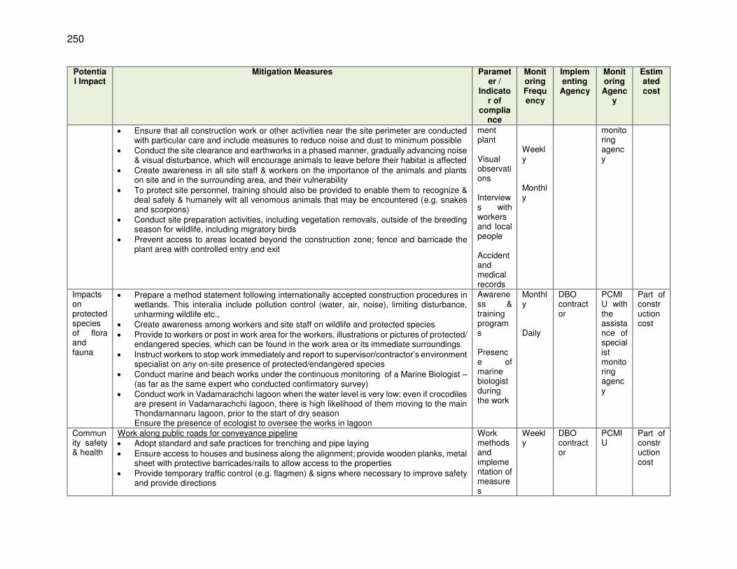
250
Potential Impact
Mitigation Measures Parameter /
Indicator of
compliance
Monitoring Frequency
Implementing
Agency
Monitoring Agenc
y
Estimated cost
Ensure that all construction work or other activities near the site perimeter are conducted with particular care and include measures to reduce noise and dust to minimum possible
Conduct the site clearance and earthworks in a phased manner, gradually advancing noise & visual disturbance, which will encourage animals to leave before their habitat is affected
Create awareness in all site staff & workers on the importance of the animals and plants on site and in the surrounding area, and their vulnerability
To protect site personnel, training should also be provided to enable them to recognize & deal safely & humanely wilt all venomous animals that may be encountered (e.g. snakes and scorpions)
Conduct site preparation activities, including vegetation removals, outside of the breeding season for wildlife, including migratory birds
Prevent access to areas located beyond the construction zone; fence and barricade the plant area with controlled entry and exit
ment plant Visual observations Interviews with workers and local people Accident and medical records
Weekly Monthly
monitoring agency
Impacts on protected species of flora and fauna
Prepare a method statement following internationally accepted construction procedures in wetlands. This interalia include pollution control (water, air, noise), limiting disturbance, unharming wildlife etc.,
Create awareness among workers and site staff on wildlife and protected species Provide to workers or post in work area for the workers, illustrations or pictures of protected/
endangered species, which can be found in the work area or its immediate surroundings Instruct workers to stop work immediately and report to supervisor/contractor’s environment
specialist on any on-site presence of protected/endangered species Conduct marine and beach works under the continuous monitoring of a Marine Biologist –
(as far as the same expert who conducted confirmatory survey) Conduct work in Vadamarachchi lagoon when the water level is very low; even if crocodiles
are present in Vadamarachchi lagoon, there is high likelihood of them moving to the main Thondamannaru lagoon, prior to the start of dry season Ensure the presence of ecologist to oversee the works in lagoon
Awareness & training programs Presence of marine biologist during the work
Monthly Daily
DBO contractor
PCMIU with the assistance of specialist monitoring agency
Part of construction cost
Community safety & health
Work along public roads for conveyance pipeline Adopt standard and safe practices for trenching and pipe laying Ensure access to houses and business along the alignment; provide wooden planks, metal
sheet with protective barricades/rails to allow access to the properties Provide temporary traffic control (e.g. flagmen) & signs where necessary to improve safety
and provide directions
Work methods and implementation of measures
Weekly
DBO contractor
PCMIU
Part of construction cost

251
Potential Impact
Mitigation Measures Parameter /
Indicator of
compliance
Monitoring Frequency
Implementing
Agency
Monitoring Agenc
y
Estimated cost
Restrict public access to all areas where construction works are on-going through the use of barricading and security personnel
Ensure that all material, equipment, workers and all activities are conducted within the demarcated / barricaded strip of land along the road; there should be no spillage of any activity outside this zone
Clearly separate work area with traffic/pedestrian flow; provide public information boards to easily identify the work area
Warning signs, blinkers will be attached to the barricading to caution the public about the hazards associated with the works such as presence of trenches / deep excavation
Plan carefully using section-by-section approach, so that open trenches are quickly closed and road restored
Control dust pollution – implement dust control measures as suggested under air quality Organize public awareness campaigns.
Visual site observations, interviews with workers and community
Safety risk due to construction vehicle/equipment movement on public roads Prepare a Transportation Plan for material, waste and equipment; consult highways
agencies, police and other relevant authorities during both planning & implementation Plan transportation routes to avoid heavily populated areas Schedule deliveries to avoid town centers and other congested areas during morning and
evening peak traffic periods Astute coordination to combine deliveries where possible, to avoid under-utilization ofon
vehicles and reduce the number of journeys Source materials in Jaffna and other local outlets wherever possible, to reduce the length
of delivery journeys Explore alternative delivery methods, (by train or sea) to the nearest point to the work site
(e.g., delivery by sea to more northerly ports such as Mannar, Trincomalee and Jaffna).
Implementation of Transportation Plan Visual site observations, interviews with workers and community
Monthly
DBO contractor
PCMIU
Part of construction cost
Safety risk due to use of local site approach roads Use only new approach road that connect via Mamune Road for movement of construction
related vehicles and equipment; do not use the new approach road that connects to Soranpattu – Thalaiyadi Road via internal roads in Thalaiyadi (surrounded by houses)
Ensure that existing roads (Mamune Road and Soranpattu – Thalaiyadi Road) are maintained in good condition to allow easy movement of heavy traffic without endangering traffic & pedestrian safety; improve roads as required, including cross drainage structures.
Visual site observations, interviews with workers and
Weekly
DBO contractor
PCMIU
Part of construction cost

252
Potential Impact
Mitigation Measures Parameter /
Indicator of
compliance
Monitoring Frequency
Implementing
Agency
Monitoring Agenc
y
Estimated cost
Conduct awareness programs and information campaigns in habitations along the roads about the movement of heavy vehicles and traffic safety measures
Provide safety, information and caution boards where necessary Schedule the transportation activities in pre-fixed timings, which should be finalized in
consultation with the local administration and community There are schools along the road, construction vehicle movement shall be restricted during
the school opening and closing hours; if unavoidable, place traffic guards at school and other sensitive places, like hospitals, religious place etc.
Provide continuous training to drivers to drive vehicles in safe & considerate manner Coordinate with the Traffic Police for temporary road diversions and for provision of traffic
aids if transportation activities cannot be avoided during peak hours. Notify affected sensitive receptors by providing sign boards with information about the
nature and duration of construction works and contact numbers for concerns/complaints
community
Occupational health & safety
Comply with IFC EHS Guidelines on Occupational Health and Safety (this can be downloaded from http://www1.ifc.org/wps/wcm/connect/9aef2880488559a983acd36a6515bb18/2%2BOccupational%2BHealth%2Band%2BSafety.pdf?MOD=AJPERES).
Prepare a comprehensive & site-specific Health and Safety Plan (H&SP) describing in detail how the health and safety of all site personnel (workers, staff and visitors) will be maintained at all times. It is to provide guidance on establishing a management strategy and applying practices that are intended to eliminate, or reduce, fatalities, injuries and illnesses for workers performing activities and tasks associated with the project. It will be important to ensure that the H&SP:
o describes all construction work processes, examines their H&S risks fully and describes action to be taken to avoid accidents, with clearly allocated responsibility for each individual action;
o covers all construction sites and work areas, including road transportation, and includes measures to protect contractor’s employees, subcontractors’ employees and the general public;
o includes regular training for all site personnel in all aspects that are relevant to their work, with the content of and attendance at all training being accurately recorded and provided monthly to the client;
o allocates responsibility for maintenance of health and safety on and off site to an H&S Manager, who is a senior member of the site management team, and has a team working under him/her, who will inspect all worksites at least weekly and will be responsible for enforcing all relevant H&S procedures;
o requires all site employees to be provided with and use Personal Protective Equipment (PPE) that is appropriate to their work duties;
Health & Safety Plan Implementation of measures Visual observations Interviews with workers
Weekly
DBO contractor
PCMIU
Part of construction cost

253
Potential Impact
Mitigation Measures Parameter /
Indicator of
compliance
Monitoring Frequency
Implementing
Agency
Monitoring Agenc
y
Estimated cost
o requires the H&S Manager to keep records of all accidents and incidents with H&S implications, and the action taken, and to review these records periodically in order to learn lessons and implement preventative action;
o requires the H&S Manager to report monthly to the client on H&S training, accidents and incidents and remedial and preventative action in the month;
o it will also be important to ensure that the H&SP is not simply a document but provides a vehicle and process through which rigorously high standards of safety are enforced throughout the project as a matter of course.
Provide compulsory H&S orientation training to all new workers to ensure that they are apprised of H&S Plan including rules of work, PPE, preventing injury to fellow workers, etc.,.
Conduct regular tool box safety briefings; leanings, causes, risks & safe procedures Conduct periodic safety audit, identify and remove potential hazard Ensure that qualified first-aid is provided at all times; equipped first-aid stations shall be
easily accessible throughout the work sites and camps. Provide medical insurance coverage to workers. Secure all installations from unauthorized intrusion and accident risks. Provide supplies of potable drinking water Provide clean eating areas where workers are not exposed to hazardous or noxious
substances. Provide visitor orientation if visitors to the site can gain access to areas where hazardous
conditions or substances may be present; visitors not to enter hazard areas unescorted Ensure the visibility of workers through their use of high visibility vests when working in or
walking through heavy equipment operating areas Ensure moving equipment is outfitted with audible back-up alarms Mark and provide sign boards for hazardous areas such as energized electrical devices
and lines, service rooms housing high voltage equipment, and areas for storage and disposal. Signage shall be in accordance with international standards and be well known to, and easily understood by workers, visitors, and the general public as appropriate.
Disallow worker exposure to high noise level for a duration of more than 8 hours per day without hearing protection. The use of hearing protection shall be enforced actively.
Additional measures for marine works Ensure that all persons engaged in the marine construction are competent swimmers Provide lifejackets as an important element of PPE and checking that they are worn at all
times Ensure the availability of properly functioning ship-to-shore communications Prohibit marine work during rough sea conditions; stop work & bringing personnel to shore
if weather conditions deteriorate significantly.
Health & Safety Plan Implementation of
Daily DBO contractor
PCMIU
Part of construction cost
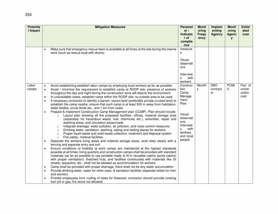
254
Potential Impact
Mitigation Measures Parameter /
Indicator of
compliance
Monitoring Frequency
Implementing
Agency
Monitoring Agenc
y
Estimated cost
Make sure that emergency rescue team is available at all times at the site during the marine work (such as rescue boat with divers)
measures Visual observations Interviews with workers
Labor camps
Avoid establishing establish labor camps by employing local workers as far as possible Avoid / minimize the requirement to establish camp at RODP site; presence of workers
throughout the day and night during the construction work will disturb the environment In unavoidable cases, establish camp within the RODP site; no outside area to be used If necessary contractor to identify a barren, vacant land (preferably private unused land) to
establish the camp nearby; ensure that such camp is at least 500 m away from habitation, water bodies, scrub lands etc., and 1 km from coast
Prepare & implement Construction Camp Management plan (CCMP). Plan should include: o Layout plan showing all the proposed facilities, offices, material storage area
(separately for hazardous waste, fuel, chemicals etc.), amenities, repair and washing areas, and circulation areas/roads
o Integrate drainage, water pollution, air pollution, and noise control measures o Drinking water, sanitation, washing, eating and resting places for workers o Proper liquid waste and solid waste collection, treatment and disposal system o Fire safety, medical facilities
Separate the workers living areas and material storage areas, work sites clearly with a fencing and separate entry and exit
Ensure conditions of livability at work camps are maintained at the highest standards possible at all times; living quarters and construction camps shall be provided with standard materials (as far as possible to use portable ready to fit-in reusable cabins (porta cabins) with proper ventilation); thatched huts, and facilities constructed with materials like GI sheets, tarpaulins, etc., shall not be allowed as accommodation for workers
Camp shall be provided with proper drainage, there shall not be any water accumulation Provide drinking water, water for other uses, & sanitation facilities (separate toilets for men
and women) Prohibit employees from cutting of trees for firewood; contractor should provide cooking
fuel (oil or gas; fire wood not allowed)
Construction Camp Management Plan Visual observations, interviews with workers and local people
Monthly
DBO contractor
PCMIU
Part of construction cost

255
Potential Impact
Mitigation Measures Parameter /
Indicator of
compliance
Monitoring Frequency
Implementing
Agency
Monitoring Agenc
y
Estimated cost
Manage solid waste according to the following preference hierarchy: reuse, recycling and disposal to designated areas; provide a compost pit for biodegradable waste, and non-biodegradable / recyclable waste shall be collected and sold in local market
Occupational & community health & safety
Additional measures for developing / managing project construction facilities (facilities, storage, office, labor camps etc.) Entire site/facility area shall be provided with hard leveled surface as appropriate; no loose
soil, water logging etc., Develop Land scaping / grasses / plantation as feasible Facilities / offices / stores shall be developed with proper construction materials Use ready
to use prefab units as far as possible Provide one-way vehicle movement in camp site as far as possible; segregate vehicle
movement in 2 way roads; provide separate entry and exit gates. All internal roads, vehicle movement /circulation / parking areas shall be properly paved to
allow easy & safe vehicle movement and avoid dust generation Mark pedestrian pathways clearly for the safe movement Store hazardous material, chemical, fuels etc. in covered place with impervious surface
(follow MSDS); display MSDS, train staff on storage & handing; ensure spillage collect and disposal system; handle these material only on impervious floors with spillage collection system
Demarcate vehicle repair & fueling areas; provide with proper impervious smooth surface, spillage & waste oil collection system, etc.
Provide caution & information boards (traffic, safety, information etc.,) Do not allow unauthorized / public entry into work sites / facilities Undertake all necessary public safety measures, precautions Ensure proper maintenance and cleanliness of the site and facilities Demarcate assembly area for emergencies Provide medical aid facilities (first aid, doctor on call etc.,) Etc.,
Health & Safety Plan Implementation of measures Visual observations Interviews with workers
Weekly
DBO contractor
PCMIU
Part of construction cost
Impacts on marine ecosystem due to construction works on beach and sea
Marine works should be scheduled to occur in the dry season (not the monsoon period) when the sea conditions are calmer to limit the spread of sediment around this operation
Conduct the excavation, and deposit the excavated material in a more controlled manner minimizing the area that is disturbed
Avoid the need to re excavation by choosing right time (calmed sea conditions again), and quickly lowering the pipes into trench and refilling
It will also be important for the contractor to enforce high standards of behavior amongst the workforce both on and off site, and to maintain clean, tidy and highly professional
Work program Visual site observation Monitoring of
Daily DBO contractor
PCMIU
Part of construction cost
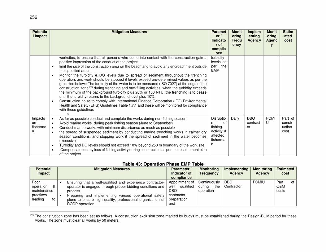
256
Potential Impact
Mitigation Measures Parameter /
Indicator of
compliance
Monitoring Frequency
Implementing
Agency
Monitoring Agenc
y
Estimated cost
worksites, to ensure that all persons who come into contact with the construction gain a positive impression of the conduct of the project
limit the size of the construction area on the beach and to avoid any encroachment outside the specified area
Monitor the turbidity & DO levels due to spread of sediment throughout the trenching operation, and work should be stopped if levels exceed pre-determined values as per the guideline below:: The turbidity of the water is to be measured (ISO 7027) at the edge of the construction zone159 during trenching and backfilling activities; when the turbidity exceeds the minimum of the background turbidity plus 20% or 100 NTU, the trenching is to cease until the turbidity returns to the background level plus 10%.
Construction noise to comply with International Finance Corporation (IFC) Environmental Health and Safety (EHS) Guidelines Table 1.7.1 and these will be monitored for compliance with these guidelines
o
turbidity levels as per the EMP
Impacts on fishermen
As far as possible conduct and complete the works during non-fishing season Avoid marine works during peak fishing season (June to September) Conduct marine works with minimum disturbance as much as possible the spread of suspended sediment by conducting marine trenching works in calmer dry
season conditions, and stopping work if the spread of sediment in the water becomes excessive
Turbidity and DO levels should not exceed 10% beyond 250 m boundary of the work site. Compensate for any loss of fishing activity during construction as per the resettlement plan
of the project
Disruption of fishing activity & affected fisherman
Daily DBO contractor
PCMIU
Part of construction cost
Table 43: Operation Phase EMP Table
Potential Impact
Mitigation Measures Parameter / Indicator of compliance
Monitoring Frequency
Implementing Agency
Monitoring Agency
Estimated cost
Poor operation & maintenance practices leading to
Ensuring that a well-qualified and experience contractor- operator is engaged through proper bidding conditions and process
Preparing and implementing various operational safety plans to ensure high quality, professional organization of RODP operation
Appointment of well qualified DBO contractor, preparation and
Continuously during the operation
DBO Contractor
PCMIU Part of O&M costs
159 The construction zone has been set as follows: A construction exclusion zone marked by buoys must be established during the Design-Build period for these
works. The zone must clear all works by 50 meters.

257
Potential Impact
Mitigation Measures Parameter / Indicator of compliance
Monitoring Frequency
Implementing Agency
Monitoring Agency
Estimated cost
adverse impacts
Ensuring that O&M manuals, RODP H&S Plan, Process Safety Management Plan, Risk Management Plan, Facilities Safety and Security Plan, and the necessary programmes for compliance with all other applicable safety regulations, are all prepared by individuals with appropriate qualifications and extensive experience.
Ensuring that the above plans and other plans and programmes, and indeed all of the work tasks involved in operating the RODP are thoroughly and professionally implemented at all times by Plant Manager
Ensuring that all of the mitigation measures discussed in this Chapter, and described along with implementation activities and schedules in Environmental Management Plant are implemented in full, in the manner described.
implementation of plans, following SOPs in O&M
Poor environmental management by DBO Contractor
Establish ISO14001 practices and certification as a good practice model that can be continued after the plant is transferred to NWSDB
ISO 14001 certification
1st year of operation Throughout the contractor period
DBO Contractor
PCMIU Part of O&M costs
Impacts of protected marine species
Individuals of the four species protected by the FFPO were translocated before construction began and these species may have recolonized the discharge area. The relocation should be repeated before the RODP begins to operate, to protect these individuals
Adopt non-discriminatory approach as far as possible to relocate all species in the area of concern irrespective of conservation status
Engage specialist agency to translocate individuals of the four protected species immediately before plant operation begins. This should cover an area of 50 m radius around the outfall. All living individuals of the 4 species should be relocated into a safe area agreed by CEA and IUCN
Reengage the specialists to resurvey the translocation area after 3 and 5 years to determine survival of translocated individuals
Survey report to confirm the presence of species, and translocation again if needed
One off before start of operation After 3 & 5 years after start of operation
DBO contractor
PMCIU Part of O&M costs
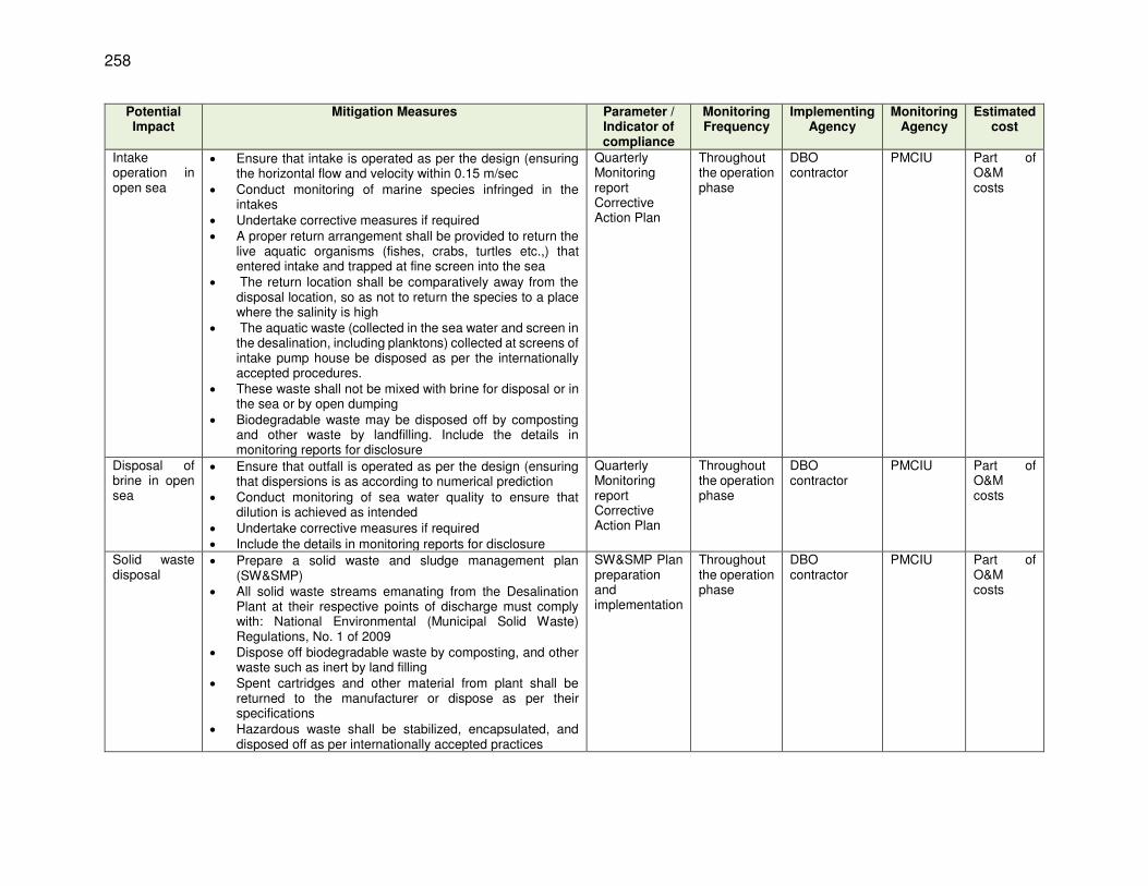
258
Potential Impact
Mitigation Measures Parameter / Indicator of compliance
Monitoring Frequency
Implementing Agency
Monitoring Agency
Estimated cost
Intake operation in open sea
Ensure that intake is operated as per the design (ensuring the horizontal flow and velocity within 0.15 m/sec
Conduct monitoring of marine species infringed in the intakes
Undertake corrective measures if required A proper return arrangement shall be provided to return the
live aquatic organisms (fishes, crabs, turtles etc.,) that entered intake and trapped at fine screen into the sea
The return location shall be comparatively away from the disposal location, so as not to return the species to a place where the salinity is high
The aquatic waste (collected in the sea water and screen in the desalination, including planktons) collected at screens of intake pump house be disposed as per the internationally accepted procedures.
These waste shall not be mixed with brine for disposal or in the sea or by open dumping
Biodegradable waste may be disposed off by composting and other waste by landfilling. Include the details in monitoring reports for disclosure
Quarterly Monitoring report Corrective Action Plan
Throughout the operation phase
DBO contractor
PMCIU Part of O&M costs
Disposal of brine in open sea
Ensure that outfall is operated as per the design (ensuring that dispersions is as according to numerical prediction
Conduct monitoring of sea water quality to ensure that dilution is achieved as intended
Undertake corrective measures if required Include the details in monitoring reports for disclosure
Quarterly Monitoring report Corrective Action Plan
Throughout the operation phase
DBO contractor
PMCIU Part of O&M costs
Solid waste disposal
Prepare a solid waste and sludge management plan (SW&SMP)
All solid waste streams emanating from the Desalination Plant at their respective points of discharge must comply with: National Environmental (Municipal Solid Waste) Regulations, No. 1 of 2009
Dispose off biodegradable waste by composting, and other waste such as inert by land filling
Spent cartridges and other material from plant shall be returned to the manufacturer or dispose as per their specifications
Hazardous waste shall be stabilized, encapsulated, and disposed off as per internationally accepted practices
SW&SMP Plan preparation and implementation
Throughout the operation phase
DBO contractor
PMCIU Part of O&M costs
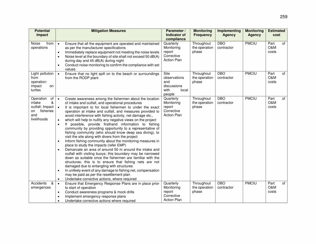
259
Potential Impact
Mitigation Measures Parameter / Indicator of compliance
Monitoring Frequency
Implementing Agency
Monitoring Agency
Estimated cost
Noise from operations
Ensure that all the equipment are operated and maintained as per the manufacturer specifications
Immediately replace equipment not meeting the noise levels Noise level at the boundary of site shall not exceed 50 dB(A)
during day and 45 dB(A) during night Conduct noise monitoring to confirm the compliance with set
values
Quarterly Monitoring report Corrective Action Plan
Throughout the operation phase
DBO contractor
PMCIU Part of O&M costs
Light pollution from operation: impact on turtles
Ensure that no light spill on to the beach or surroundings from the RODP plant
Site observations and discussions with local people
Throughout the operation phase
DBO contractor
PMCIU Part of O&M costs
Operation of intake & outfall: Impact on fisheries and livelihoods
Create awareness among the fishermen about the location of intake and outfall, and operational procedures
It is important to for local fishermen to under the exact operation at intake and outfall, and measures provided to avoid interference with fishing activity, net damage etc.,
which will help to nullify any negative views on the project If possible, provide firsthand information to fishing
community by providing opportunity to a representative of fishing community (who should know deep sea diving), to visit the site along with divers from the project
Inform fishing community about the monitoring measures in place to study the impacts (refer EMP)
Demarcate an area of around 50 m around the intake and outfall with visiting buoys; this boundary may be narrowed down as suitable once the fishermen are familiar with the structures; this is to ensure that fishing nets are not damaged due to entangling with structures
In unlikely event of any damage to fishing net, compensation may be paid as per the resettlement plan
Undertake corrective actions, where required
Quarterly Monitoring report Corrective Action Plan
Throughout the operation phase
DBO contractor
PMCIU Part of O&M costs
Accidents & emergences
Ensure that Emergency Response Plans are in place prior to start of operation
Conduct awareness programs & mock drills Implement emergency response plans Undertake corrective actions where required
Quarterly Monitoring report Corrective Action Plan
Throughout the operation phase
DBO contractor
PMCIU Part of O&M costs

260
C. Environmental Monitoring Plan
569. Table 44 and 45 provide the Environmental Monitoring Plan for the project, which considers each of the monitoring activities proposed in the EMP and sets out in some detail how each should be conducted.

261
Table 44: Environmental Monitoring Plan (Design & Construction Phase) Monitoring field Monitoring location Monitoring parameters Frequency Responsibility Estimated
Cost
Confirmatory survey : presence of protected flora species in the project site
RODP plant site and proposed 2 new access road, and intake and outfall alignment
Presence of 4 plant species (Sesuvium portulacastrum, Halosarcia indica, Salicornia brachiate and Citrullus colocynthis)
One off during design stage prior to finalization of layout plan
DBO Contractor via preapproved agency
Lump sum costs: US$ 5,000
Field surveys to detect presence of protected bird species
RODP plant site and proposed 2 new access road, and intake and outfall alignment
Presence of 2 bird species (painted stork, and spot-billed pelican), trees with nests, etc.,
Six months prior to start of construction, and just before start of construction work
DBO Contractor via preapproved agency
Lump sum costs: US$ 5,000
Confirmatory survey : presence of protected reptiles species
In & around (within 1 km boundary) RODP plant, beach.
Presence of 2 reptile species (salt water crocodile & hawkbill turtle) – direct and indirect methods as appropriate (to be finalized by experts during implementation)
One off during the design phase Continuously during the marine and beach works phase
DBO Contractor via preapproved agency
Lump sum costs: US$ 10,000
Sea water quality
5 locations Near the shore (50 m inside), at intake, outfall locations at 2 control points (1 in sea
current direction & 1 perpendicular to sea current direction 1km away from intake)
All physic-chemical, heavy metal, pesticides and bacteriological parameters
One-off: Baseline monitoring prior to start of construction work One-off: Updated baseline after completion of all construction works & just prior to start of operation
DBO Contractor Lump sum: US$ 6,000
3 points (at work site, 50 m from work site & 100 m from work site)
Turbidity & DO Daily during marine construction Hourly
DBO Contractor Lump sum: US$ 20,000
Same as above Turbidity, TSS, TDS, oil & grease, & trace chemicals (to be finalized during detailed design)
Fortnightly: During beach & marine works Bimonthly: During RODP /land based works
DBO Contractor Lump sum: US$ 30,000
Vadamarachchi Lagoon water quality
2 locations: In the lagoon - where
drainage line from RODP site joins the lagoon
In the lagoon - near the road bridge
All physic-chemical, heavy metal, pesticides and bacteriological parameters
One-off: Baseline monitoring prior to start of construction work
DBO Contractor Lump sum: 1500 USD

262
Monitoring field Monitoring location Monitoring parameters Frequency Responsibility Estimated Cost
Same above Turbidity, DO, TSS, TDS, oil & grease, & trace chemicals (to be finalized during detailed design)
Bimonthly: During RODP /land based works
DBO Contractor Lump sum: 6000 USD
2 locations: In the lagoon - near the work
site In the lagoon - near the road
bridge
Turbidity, TSS, TDS, oil & grease, & trace chemicals (to be finalized during detailed design)
Fortnightly: During conveyance pipeline works in lagoon
DBO Contractor Lump sum: 2500 USD
Ambient air quality & noise
4 locations Within RODP site Just outside the RODP site
(downwind direction) In Thalaiyadi village along
Soranpattu Road Near the sea
PM10, PM2.5 NO2, SO2, CO, HC
24 hour noise levels
One-off: Baseline monitoring prior to start of construction work One-off: Updated baseline after completion of all construction works & just prior to start of operation
DBO Contractor Lump sum: 5000 USD
- Same as above- PM10, PM2.5 NO2, SO2, CO, HC
24 hour noise levels
Monthly: during RODP construction work
DBO Contractor Lump sum: 25,000 USD
3 points: Maruthankerny Near the conveyance pipeline
works (this point will change as per the work location)
Vadamarachchi lagoon
PM10, PM2.5 NO2, SO2, CO, HC
24 hour noise levels
Monthly: during Conveyance pipeline construction
DBO Contractor Lump sum: 15,000 USD
Marine productivity (planktons), fish composition & production
6 locations at intake, at outfall 500 m from the outfall 1000 m from the outfall 2 control points at
neighbouring fishing villages to be identified during detailed design phase to act as control points for monitoring)
Composition, concentration, density and abundance of Benthos, phytoplankton and zooplankton
Baseline prior to start of construction Updated baseline after marine construction & prior to start of operation (baseline to be established quarterly to coincide with all seasons
DBO Contractor via preapproved agency
Lump sum: 30,000 USD

263
Monitoring field Monitoring location Monitoring parameters Frequency Responsibility Estimated Cost
3 locations Thalaiyadi village & 2 neighbouring fishing villages to be identified during detailed design phase to act as control points for monitoring
Secondary data from Fisheries Department: Latest data Fish catch per unit effort Key species
Separate data for type of fishing (eg, Ma del fishing) to collected
One-off : Baseline prior to start of construction work
PCMIU No additional costs
-same as above- Sample surveys Fish catch per unit effort Key species Plankton density & key species
One-off : Baseline prior to start of construction work Annually: during construction work Annually: during operation phase
PCMIU Lump sum: 20,000 USD

264
Table 45: Environmental Monitoring Plan (Operation phase) Monitoring field Monitoring location Monitoring parameters Frequency Responsibility Cost & Source of
Funds
Environmental management of RODP by DBO Contractor
- ISO 14001 certification 1st year of operation Throughout the contractor period
DBO Contractor O&M costs
Sea (source) water quality
Intake All physic-chemical, heavy metal, pesticides and bacteriological parameters
Yearly twice DBO Contractor O&M costs (water quality will be tested at the internal laboratory part of RODP)
Monitoring of quality of water supplied to consumers
Consumer end- random sampling in all zones
Parameters as per drinking water quality standards,
Monthly once DBO Contractor Same above
Brine concentrate Outfall pumping station at RODP
Parameters as per the marine disposal standards of
Monthly once DBO Contractor Same above
Sea water quality 5 locations -at disposal point - at 25 m from disposal point -at 100 m from disposal point -at 2 control points selected in baseline
Turbidity, DO, salinity, TDS, TSS, oil & grease, trace elements, heavy metals etc., (parameters to be finalized during detailed design)
Quarterly once (yearly 4 times, to cover calm and turbulent conditions)
DBO Contractor Same above
Sludge quality Sludge from various units of RODP
Physio chemical, and hazardous properties (parameters to be finalized during detailed design stage)
Yearly once DBO Contractor O&M costs (sludge quality will be tested at the internal laboratory part of RODP)
Marine productivity (planktons), fish composition & production
6 locations at intake, at outfall 500 m from the outfall 1000 m from the outfall 2 control points at neighbouring fishing villages as established during the design
Composition, concentration, density and abundance of Benthos, phytoplankton and zooplankton
Quarterly during initial 2 years, of operation Yearly twice
DBO Contractor via preapproved agency
Lump sum: 54,000 USD
Marine productivity, fish composition & production
3 locations Thalaiyadi village & 2 neighbouring fishing villages to be identified during detailed design phase to act as control points for monitoring
Secondary data from Fisheries Department: Latest data Fish catch per unit effort Key species Separate data for type of fishing (eg, Ma del fishing) to collected
Yearly once PCMIU No additional costs

265
Monitoring field Monitoring location Monitoring parameters Frequency Responsibility Cost & Source of Funds
Environmental management of RODP by DBO Contractor
- ISO 14001 certification 1st year of operation Throughout the contractor period
DBO Contractor O&M costs
-same as above- Sample surveys Fish catch per unit effort Key species Plankton density & key
species
Yearly Once
DBO Contractor Lump sum: 21,000 USD
Noise levels 4 locations Within RODP site Just outside the RODP
site (downwind direction) Nearest house in
Thalaiyadi village In Thalaiyadi village along
Soranpattu Road Near the sea
24 hour noise levels Monthly once DBO Contractor Lump sum: 21,000 USD
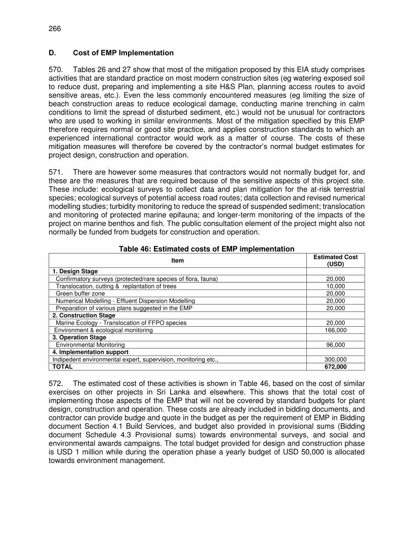
266
D. Cost of EMP Implementation
570. Tables 26 and 27 show that most of the mitigation proposed by this EIA study comprises activities that are standard practice on most modern construction sites (eg watering exposed soil to reduce dust, preparing and implementing a site H&S Plan, planning access routes to avoid sensitive areas, etc.). Even the less commonly encountered measures (eg limiting the size of beach construction areas to reduce ecological damage, conducting marine trenching in calm conditions to limit the spread of disturbed sediment, etc.) would not be unusual for contractors who are used to working in similar environments. Most of the mitigation specified by this EMP therefore requires normal or good site practice, and applies construction standards to which an experienced international contractor would work as a matter of course. The costs of these mitigation measures will therefore be covered by the contractor’s normal budget estimates for project design, construction and operation. 571. There are however some measures that contractors would not normally budget for, and these are the measures that are required because of the sensitive aspects of this project site. These include: ecological surveys to collect data and plan mitigation for the at-risk terrestrial species; ecological surveys of potential access road routes; data collection and revised numerical modelling studies; turbidity monitoring to reduce the spread of suspended sediment; translocation and monitoring of protected marine epifauna; and longer-term monitoring of the impacts of the project on marine benthos and fish. The public consultation element of the project might also not normally be funded from budgets for construction and operation.
Table 46: Estimated costs of EMP implementation
Item Estimated Cost
(USD) 1. Design Stage Confirmatory surveys (protected/rare species of flora, fauna) 20,000 Translocation, cutting & replantation of trees 10,000 Green buffer zone 20,000 Numerical Modelling - Effluent Dispersion Modelling 20,000 Preparation of various plans suggested in the EMP 20,000 2. Construction Stage Marine Ecology - Translocation of FFPO species 20,000 Environment & ecological monitoring 166,000 3. Operation Stage Environmental Monitoring 96,000 4. Implementation support Indipedent environmental expert, supervision, monitoring etc., 300,000 TOTAL 672,000
572. The estimated cost of these activities is shown in Table 46, based on the cost of similar exercises on other projects in Sri Lanka and elsewhere. This shows that the total cost of implementing those aspects of the EMP that will not be covered by standard budgets for plant design, construction and operation. These costs are already included in bidding documents, and contractor can provide budge and quote in the budget as per the requirement of EMP in Bidding document Section 4.1 Build Services, and budget also provided in provisional sums (Bidding document Schedule 4.3 Provisional sums) towards environmental surveys, and social and environmental awards campaigns. The total budget provided for design and construction phase is USD 1 million while during the operation phase a yearly budget of USD 50,000 is allocated towards environment management.

267
E. Institutional Arrangements
573. The Ministry of Water Supply and Drainage (MWSD) is the Executing Agency (EA) with overall responsibility for JKWSS Project; and the Implementing Agency (IA) responsible for construction and operation is the National Water Supply and Drainage Board (NWSDB) for water supply and sanitation, including the RODP. 574. The NWSDB set up a Project Management Coordination and Implementation Unit (PMCIU) in Jaffna to oversee detailed design and construction supervision (by the DSC), national level coordination, preparation of O&M manuals and other guidelines, capacity building, and other aspects common to both water supply and sanitation components. PMCIU staff will comprise a Project Director, two Engineers (water supply and sanitation), a Procurement Officer, a Land Acquisition and Resettlement Officer, and an Environmental Officer, plus support staff. These key technical and managerial staff are supported by consultants funded by the project including specialists to assist in monitoring and supervising implementation of the EMP and in coordinating any land acquisition and resettlement activities. 575. The RODP design and construction will be directly supervised by PCMIU with the assistance of DSC. 576. The project will be overseen by a National Project Coordination Committee (NPCC), with membership comprising Secretaries of relevant ministries, representatives from other relevant institutions/agencies and senior staff of the PMCIU and PIU. There will also be a provincial Project Coordinating Committee in Jaffna (PCC) with representatives from all relevant government organizations, relevant NGOs and other interested parties, whose main role will be in project oversight at local level, reporting to the NPCC. 577. Detailed designs will be prepared by DBO Contractor in this design-build contract approach. PMCIU must ensure that all recommendations and investigations recommended in EIA and EMP are implemented effectively. To this effect, besides, Environmental officer, PMCIU may engage services of LHI and IUCN Sri Lanka for conducting confirmatory surveys, and overseeing and monitoring the construction work. These agencies may be engaged utilising the provisional sums provided in the contract. The PMCIU must also ensure that a qualified and experienced environmental specialist is engaged in DSC continuously during the design and construction phase of RODP. The functions and responsibilities of the Environmental Officer, supported by environmental specialist of DSC, shall include the following:
(i) Oversee that the environmental/technical requirements and administrative policies and recommendations are properly integrated in the designing and planning as well as during construction and operation of the project;
(ii) Coordinate the EIA update and EMP (iii) Ensure that all the field, confirmatory surveys, baseline surveys and monitoring are
conducted as per the EIA and EMP (iv) Oversee the monitoring activities during construction and operation phases of the
project conducted by others; (v) Ensure that mitigating measures and preventative activities are properly
implemented and adequate measures are taken in cases where unexpected impacts arise;
(vi) Prepare Environmental Monitoring Plans and regular reports on the activities undertaken and the results of monitoring for submission to appropriate authorities (ADB and CEA).

268
(vii) Submit quarterly Environmental Monitoring Plan to ADB for disclosure (Template of monitoring plan is provided in Appendix M)
578. PMCIU will also engage agencies like LHI and IUCN Sri Lanka during the implementation to provide necessary advise to finalize the updated EIA and EMP implementation and monitoring. 579. Independent monitoring. An International Environmental Monitoring Specialist (EMS) with expertize in management and monitoring of environmental impacts of development projects in marine and coastal environments, will be engaged during implementation and operation phase of DBO contract. EMP will undertake independent monitoring of implementation of EMP related to the final and approved EIA in compliance with ADB SPS (2009) and advise PMU and ADB accordingly. EMS will also conduct field sample surveys where required with the help of outside laboratories/agencies (like LHI). Terms of Reference for the EMS is provided in Appendix S. 580. Monitoring Committee. An External Environmental Monitoring Committee will be formed consisting of representatives, authorities/agencies that have jurisdiction over concerned project activities or premises and communities to be affected by construction or operation of the projects. This external committee, formed from members of the following agencies, will oversee the implementation of EMP:
(i) National Water Supply and Drainage Board (Project Implementing Agency); (ii) Jaffna Municipal Council; (iii) Central Environmental Authority (CEA) (iv) Coast Conservation Department (CCD); (v) Department of Fisheries, District Office , Jaffna (vi) IUCN Sri Lanka / reputed Environmental NGO (vii) Fishermen’s Society.
F. Future Review and Revision of Documents
581. As already noted in the foregoing text, this EIA study was conducted in the pre-tender period based on feasibility study, before designs had been prepared. Guidance on potential approaches to construction and operation was obtained from experienced engineers and desalination experts, and descriptions of the likely construction and operation processes were prepared accordingly, adopting the basic operational parameters provided by the Feasibility Study and in tender documents for the DBO contract. Potential impacts of the project were assessed on the basis of these descriptions and with the aid of data on the exiting environment of the project site and its environs obtained from published literature, and supplemented by new data from surveys conducted during the EIA study. 582. The resulting assessment of impacts presented above is intended to provide a thorough and accurate analysis of the potential impacts of construction and operation of the project, and the likely significance of those impacts, if the plant is built and operated, and if the operational characteristics remain as outlined in Section IV.. It is also intended that the mitigation proposed to address potential negative impacts and described in the above EMP is appropriate, practical and cost effective; and that the monitoring proposed in the EMP will assist in mitigation design and implementation, and that by documenting the actual impacts of the project the concerns of the local community will be assuaged, and the project proponent and national environmental authorities will be confident that the project is not producing significant negative impacts. 583. The EIA and EMP will be updated at detailed design stage and revisited at key stages throughout the project, and will be updated at each stage to reflect any changes in design or

269
approach, and to amend the impact assessment and mitigation and monitoring proposals as may be necessary. This process will also allow any unforeseen impacts to be documented, mitigated and monitored. The EIA report will be reviewed and updated at the following key stages: a) after finalisation of designs; b) during construction (months 6 and 18); c) at the end of plant commissioning (i.e. before operations begin); and d) at the end of the first and second years of plant operation. The review and revision process will be conducted by the DBO Contractor with the assistance of an Environmental Expert, and reviewed by the PMCIU and ADB, and approved. It should be emphasised that it may not be necessary to revise the document at each stage, as this should only be done to address significant deviations from what is presented above. 584. As also noted above, the contractor will also prepare two other key environmental documents, which are the Contractor’s Environmental Management Plan (Construction Stage) and the Contractor’s Environmental Management Plan (Operation Stage). These will be prepared at least two months before each stage begins, to allow time for review and revision if necessary. These are very important documents, because in each case they provide the contractor’s response to the client’s EMP and EMoP presented above, and explain in detail how the contractor will provide each mitigation or monitoring measure that is their responsibility, and how they will maintain the environmental performance of their site(s) (construction and operation), by implementing additional pollution control and environmental management activities if appropriate. Appendix N provides an outline of a Contractor’s Construction Stage EMP, which may be followed if necessary, and Appendix O provides guidance on issues that should be addressed in the Contractor’s Operation Stage EMP.
X. CONCLUSIONS AND RECOMMENDATIONS
A. Conclusions
585. Initial studies suggested that the project location may not be greatly sensitive in environmental and socio-economic terms. The site is owned by the Government and the on-land area is unoccupied and not used for any economic purpose, apart from occasional small-scale illegal sand mining. The nearest inhabitation is 750 m away, where there are three small villages, with 1,351 inhabitants. The site is covered by a scrub type of vegetation, which is found all along this part of the Jaffna coastline and elsewhere in the country. Surveys of the adjacent sea area in which the intake and outfall pipelines will be located showed that the seabed is sandy, with low numbers of common invertebrates and fish; and there is no coral, sea grass or other important habitats. The area is licenced for the traditional Madel (beach seine) fishery, but local people reported that the fishery has lapsed in recent years because of low returns. Fishing is the main occupation, but this is mainly conducted in deeper water. 586. Detailed analysis of survey data showed however that there are certain sensitive features of the site and its environs; and the environmental assessment (presented in Sections VI and VII) found that these need to be handled carefully to avoid potentially significant negative impacts. The key issues are as follows:
(i) The list of species found at the project site includes three that are “at-risk” in conservation terms, according to national and international red data lists; and eight other at-risk species are reported from the vicinity and might therefore also be present. No notable impact on these protected species envisaged. Confirmatory surveys needs to be conducted, and mitigation and monitoring measures are suggested should be implemented.
(ii) Although none of the species found in the marine environment are rare or endangered, four are protected under the Fauna & Flora Protection Ordinance

270
(2009), ostensibly to prevent exploitation in the marine aquarium industry; individuals of these species need to be translocated from the marine pipeline routes before construction begins and from the vicinity of the outfall before the plant starts to operate.
(iii) Another issues is of intake operation in open sea that may have impacts on marine species by way of infringement, entrapment and entrainment in intake pipe and screens. This issues has been studied, and concluded that with proper construction of intake, and provision of appropriate size screens, the impact will be negligible. It is also suggested to monitor this aspect during the operation phase.
(iv) Fishing is the main source of income locally and returns are low, so people are understandably worried that construction and operation of the plant could affect local stocks and livelihoods. The EIA concludes that significant declines of fish populations are unlikely, and that the benthic habitat may have been seriously damaged by local fishing methods. Nevertheless, local concerns will be addressed through monitoring surveys and dissemination of information. These are included in the Environmental Monitoring Plan. Regular meetings, information disclosure and grievance redress is proposed.
(v) Numerical modelling predicted that brine discharges will raise salinities in a very small area (22 m radius) and that there will therefore be no significant changes in water quality or ecology in the discharge zone. Monitoring will be conducted during the operation stage.
587. These are the main environmental risks of the project and in each case, detailed avoidance or mitigation measures are described in the EMP (Tables 41 and 43). Several of the issues also require monitoring, and this is described in Environmental Monitoring Plan (Table 44-45). 588. Most of the other potential impacts of building the RODP and associated facilities are those that are common to most construction sites regardless of the type of scheme or its location. These include: creation of dust and the associated risks to the health of workers and others; risk of pollution from leaks or spills of chemicals used and stored on site; risks to the health and safety of workers and others both on and off-site; generation of noise by site equipment and operations; etc. These and other impacts will be mitigated by standard measures that are common practice on most modern construction sites. These include: dampening exposed soil to reduce dust and phasing the removal of site vegetation to take advantage of its soil stabilising properties; storing chemicals as prescribed by international standards and containing and treating drainage before discharge; preparing a comprehensive H&S Plan and enforcing strict adherence; and locating mechanical machinery in remote areas of the site and ensuring any workers nearby wear ear defenders. Proposed to conveyance pipeline passes through Vadamarachchi lagoon, impacts due to this work are identified as degradation of water quality, and disturbance to bird species. 589. Once the completed plant begins to function, the main environmental risk is that it could cause environmental and social impacts if it was not operated as intended. Chief amongst these is the risk of providing water that does not meet the expected quality standards, and/or failing to deliver the expected quantities, which could affect the health of consumers and create significant hardship as a result of the disrupted supply. There are also risks that inadequate site management could cause localised pollution, and that small-scale and more widespread plant failures could cause more significant impacts. These and other potential impacts of the operational phase will be avoided if the plant is operated in the expected professional manner throughout its active life, so key aspects of the mitigation plan require the client body to take great care in appointing contractors and especially in evaluating their senior staff to ensure that all key positions are filled

271
by highly qualified, dedicated and experienced individuals. The operation-phase EMP also requires that pollution prevention measures like chemical storage facilities are designed to international standards, and that the plant is equipped with state-of-the-art automatic monitoring and control systems throughout, as proposed in the Feasibility Study. 590. The overall aim of the project is to contribute significantly to improving the living conditions and public health of the Jaffna community by providing a reliable supply of high quality drinking water to a high proportion of local residents, and to provide the basis for a future expansion that could supply all of the peninsula’s needs. Given the deprivation that this area has suffered in the recent past, these will be major achievements, with highly significant social and environmental benefits, when the project comes on stream. 591. The EIA study has shown that there is a degree of sensitivity in both natural and human environments at and around the project site, which will need careful handling to avoid what could be significant adverse impacts. The framework for successful avoidance of these and the other less significant impacts is provided by the EMP included above, and the rationale is explained in the foregoing environmental assessment. If these measures are implemented thoroughly, as described in this document, then it should be possible to build and operate the RODP at this site without significant negative impacts. B. Recommendations
592. The key role of the EMP in avoiding potential negative impacts is very clear from the above conclusions; so the main recommendation from this study is that the PMCIU should ensure that the mitigation measures and constituent activities that are defined clearly in those documents are implemented as specified. 593. The process of regular review and revision of the EIA and EMP by the DBO contractor is very important as it provides the mechanism through which any changes in design or construction and operation methodologies can be properly assessed, and mitigation can be amended if appropriate. The second recommendation is therefore that the PMCIU should ensure that the EIA review and revision process is conducted according to the timetable proposed in Section X.F and that the revisions accurately reflect any significant project changes. Updated EIA shall be submitted to ADB for approval. Revisions that occur in the construction stage should also reflect any unanticipated impacts that may have occurred. 594. The other documents that the contractor is required to produce are the Contractor’s Construction Stage and Operation Stage EMPs, and these are also very important as they should explain in detail how the contractor intends to provide each mitigation measure for which he is assigned responsibility in the project EMP above. The PMCIU should therefore ensure that these documents are thorough, detailed, and cover all relevant mitigation specified in the EMP. They should also incorporate the detailed guidance provided in Appendices E (construction stage) and F (operation stage) below as appropriate. Once the documents are prepared it is extremely important that the mitigation activities are implemented in a diligent and timely manner, so the PMCIU should also ensure that supervision of these activities by the Supervising Consultant’s environmental specialists is robust and effective at all times, that the contractor complies fully with all instructions, and that construction or operation needs are not allowed to override environmental protection requirements at any stage.

APPENDICES A to S
(Available upon Request)