environmental impact assessment (annexes 1 9b) oil cooler, compressor ... (iso rated) gas turbine...
TRANSCRIPT
Environmental Impact Assessment (Annexes 1–9b) May 2016
Bangladesh: Power System Expansion and
Efficiency Improvement Investment Program
(Tranche 3)
Ashuganj 400 MW Combined Cycle Power Plant
(East)
Prepared by Ashuganj Power Station Company Limited (APSCL) for the Asian Development Bank. This is an updated version of the draft EIA posted in October 2015 available on http://www.adb.org/projects/documents/ashuganj-400mw-ccpp-east-updated-eia
This environmental impact assessment is a document of the borrower. The views expressed
herein do not necessarily represent those of ADB's Board of Directors, Management, or staff,
and may be preliminary in nature. Your attention is directed to the “terms of use” section on
ADB’s website.
In preparing any country program or strategy, financing any project, or by making any designation of or reference to a particular territory or geographic area in this document, the Asian Development Bank does not intend to make any judgments as to the legal or other status of any territory or area.

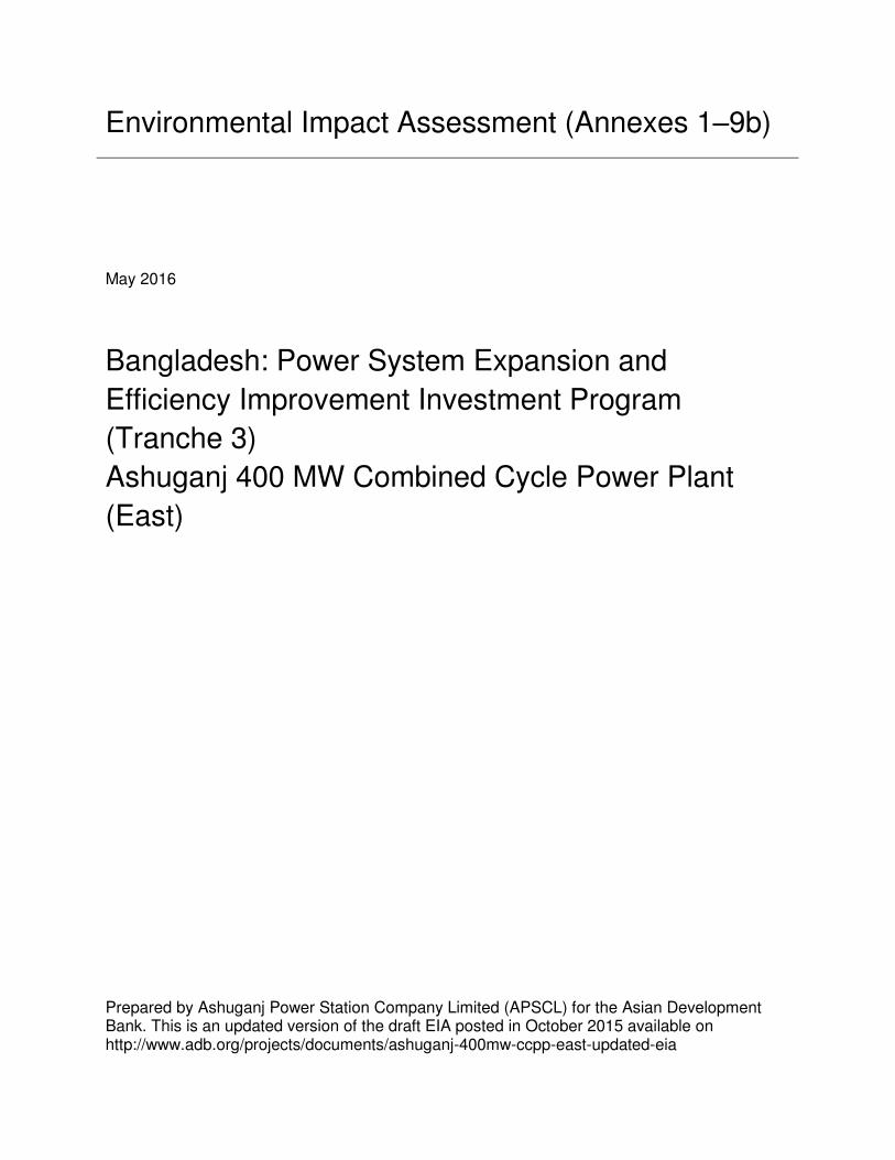
Annexure-1
Project Layout of Ashuganj
400MW CCPP (East)

Annexure-1(a)
Layout Plan of Ashuganj
400MW CCPP (East)
CLEleva
tion +
1.25m
CW Pipe Ø1.25m
Ø1.25m
Over head C
able Tray 6 m high
Pump
Statio
n
Dis
charg
e P
oin
t

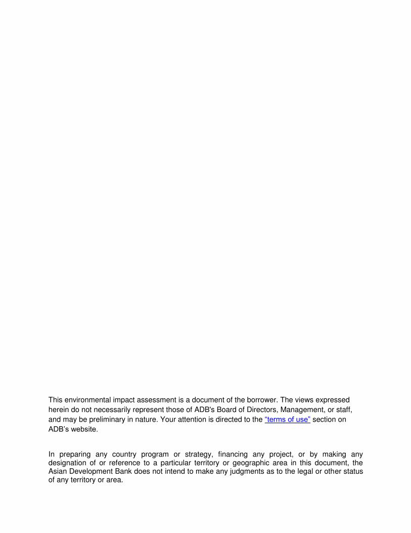
Annexure-1(b)
Project Area with Existing
Structures
Ø1.25m
able Tray 6 m high
Area for
Ashuganj
400 MW
CCPP
(East)
Annexure-1(c)
Summary of Existing and
Proposed Power plants at
APSCL

Name of the Plants
Installed / Derated Capacity
(MW)
Date in service
Status Average Gas Use (m3/day)
Total Water use
(m3/hr)
To be Replaced
By
Average Gas Use (m3/day)
Water use (m3/hr)
COD of new Units
Cooling water for condenser (Raw
river water)
Raw river water for cooling various
equipments.i.e feed pump,
lub oil cooler, compressor
etc
Raw river water for Closed cooling water circuit
River water for water treatment plant to produce
demi water
River water for General use ( Office
and residential
area) Total Water use
(m3/hr)
ASHUGANJ POWER STATION COMPANY LTD
ST 1 (Unit 1) 64/50 17.08.1970 In Operation 268,493 11,000
a) 225MW CCPP, b) 450MW CCPP (South) & c) 450MW CCPP (North)
a) 926,410 for 225MW CCPP, b) 13,98,860 for 450MW CCPP (South) & c) 13,94,601 for 450MW CCPP (North)
a) 22,000 for 225MW CCPP, b) 29,000 for 450MW CCPP (South) & c) 30,000 for 450MW CCPP (North)
Simple Cycle (225MW): April'15;
Combined Cycle
(225MW): November'15
10,200
650 - - 150
1 11,000
ST 2 (Unit 2) 64/50 08.07.1970 In Operation 268,493 11,000 January'16
(450MW South)
10,200
650 - - 150
1 11,000
GT 1 56/40 15.11.1982 Retired in Feb,
2014 263,014 -
February'17 (450MW North)
- - - - - -
GT 2 56/40 23.03.1986 In Operation 263,014 - - - - - - -
ST - GT 1 (CCPP)
34/20 28.03.1984 Retired in Feb,
2014 - 5,200
5,000
200 - - - 5,200
ST 3 (Unit 3) 150/130 17.12.1986 In Operation 710,274 36,000 400MW CCPP (East)
13,94,600 31,000 2020 28,500 -
1,965
35
- 30,500
ST 4 (Unit 4) 150/150 05.04.1987 In Operation 838,134 36,000 34,000 -
1,965
35
- 36,000
ST 5 (Unit 5) 150/135 21.03.1988 In Operation 719,785 36,000 34,000 -
1,965
35
- 36,000
50 MW GE 50/50 30.04.2011 In Operation 203,889 - - - -
- - -
225MW
CCPP,
19,800 -
2,000 1502
50 22,000
450MW
CCPP (South)
27,000 -
1,800 1503
50 29,000
450MW
CCPP (North)
28,150 -
1,800 -
50 30,000
Note 1: Used for Unit-1,2,3,4,5,Office and Residence
Note 2: Used for Unit-1,2,3,4&5
Note 3: Used for 450MW(South) & 450MW(North)

NON-ASHUNGONJ POWER PLANT
Name of the Plants
Installed / Derated Capacity
(MW)
Date in service
Status Average Gas Use (m3/day)
Total Water use
(m3/hr)
Aggreko Gas Engine 95/95 16-Mar-11 In Operation
563,958 -
Precision Gas Engine 55/55 29-Mar-09 In Operation
285,209 -
United Ashuganj Gas Engine 53/53 17-Jun-11 In Operation
259,106 -
United Modular Ashuganj Gas Engine
195/195 22-Apr-15 In Operation
984,309 -
Midland Gas Engine 50/50 7-Dec-13 In Operation
261,900 -
TOTAL
GRAND TOTAL
Daily Average
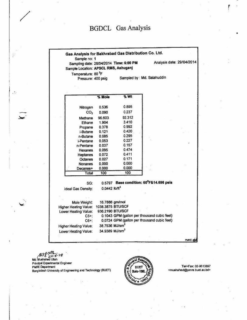
Annexure-2
Gas Specification

Annexure-3
Gas Interconnection Layout

EXISTING BAKHRABAD GAS RMS FOR
Fig - 2.03
ASHUGANJ POWER STATION COMPANY LTD.
FEASIBILITY STUDY FOR

Annexure-4
Electrical Interconnection
Layout
B.LIMIT
DISCH
AR
GE CH
AN
EL
DIS
CH
AR
GE C
HA
NEL
W L
R P P
DISCHARGE CHANNEL
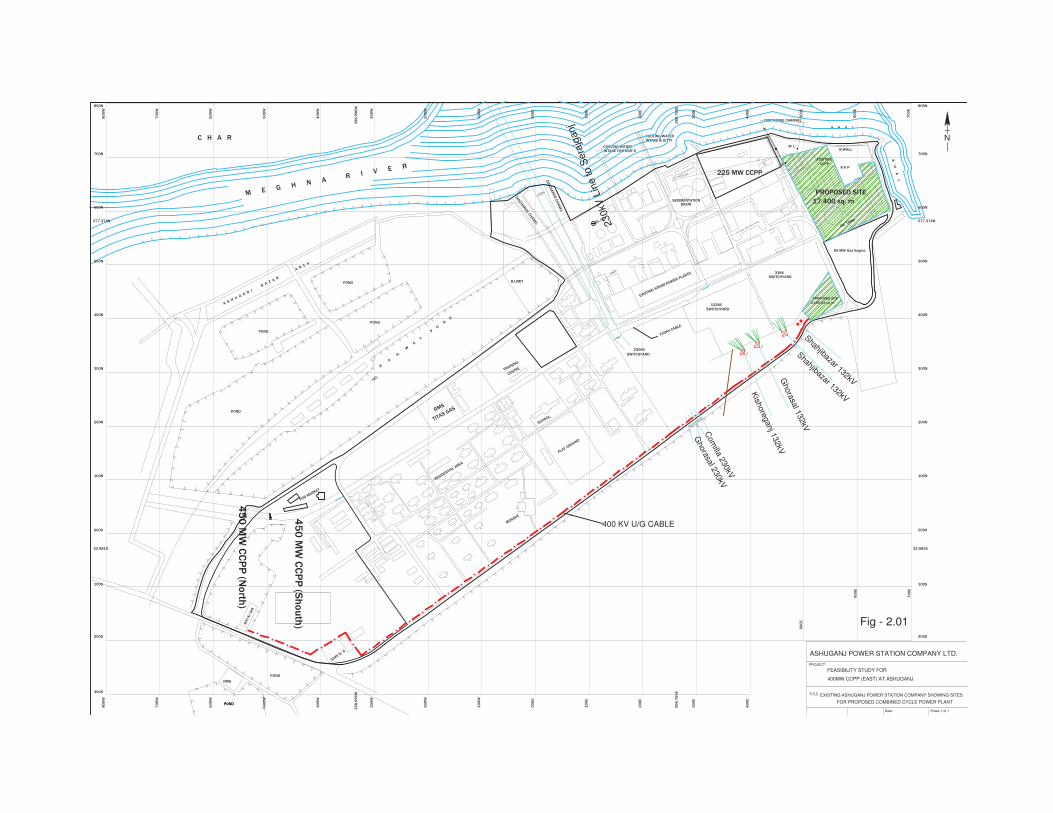
FOR PROPOSED COMBINED CYCLE POWER PLANT
EXISTING ASHUGANJ POWER STATION COMPANY SHOWING SITES
COOLING WATER INTAKE & JETTY
INTAKE FOR UNIT-5COOLING WATER
A S H U
G A
N J
B
A Z A
R
A R
E A
B-WALL
K H A L
K H
A L
R
A
IL
W
A
Y
P
O
N
D
BASINSEDIMENTATION
CCPPEXISTING
OIL TANK
33KVSWITCHYARD
SWITCHYARD132KV
SWITCHYARD
230KV
MOSQUE
PLAY GROUND
SCHOOL
CENTRETRAINING
RMS
PDB MARKET
33KV S/.S
RMS
POND
POND
POND
POND
POND
POND
M E G H N A R I
V E R
C H A R N
CL
EL 00
100N
TITAS GAS
Over head C
able Tray 6 m high
POND
30
0E
26
6.7
65
E
20
0E
10
0E
00
00
10
0W
20
0W
30
0W
40
0W
50
0W
60
0W
70
0W
40
0E
50
0E
60
0E
70
0E
32
8.9
96
W
200S
100S
0000
80
0W
30
0E
26
6.7
65
E
20
0E
10
0E
00
00
10
0W
20
0W
30
0W
40
0W
50
0W
60
0W
70
0W
40
0E
32
8.9
96
W
80
0W
50
0E
60
0E
70
0E
300S
100N
200N
300N
400N
500N
600N
700N
800N
200S
100S
0000
300N
200N
400N
500N
600N
700N
800N
577.374N577.374N
32.981S32.981S
132KV CABLE
225 MW CCPP
45
0 M
W C
CP
P (S
ho
uth
)
TITLE
Date :
PROJECT
ASHUGANJ POWER STATION COMPANY LTD.
FEASIBILITY STUDY FOR
Sheet-1 of 1
Fig - 2.01
EXISTING STEAM POWER PLANTS
RESIDENTIAL AREA
Shahjibazar 132kV
45
0 M
W C
CP
P (N
orth
)
50 MW Gas Engine
Ghora
sal 2
30kV
Com
illa 2
30kV
Ghora
sal 1
32kV
Shahjibazar 132kV
230kV
Lin
e to S
era
jganj
Tow
er
Tow
er
Kish
ore
ganj 1
32kV
400MW CCPP (EAST) AT ASHUGANJ
PROPOSED SITE
17,400 sq. m
PROPOSED SITE
3,195.03 sq. m
40
0 K
v G
IS
400 KV U/G CABLE
Annexure-5
Plant and Machinery
Plant and Machinery
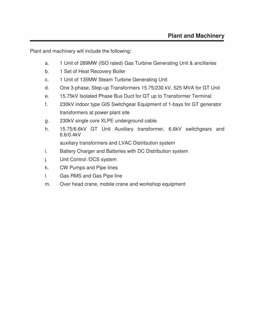
Plant and machinery will include the following:
a. 1 Unit of 289MW (ISO rated) Gas Turbine Generating Unit & ancillaries
b. 1 Set of Heat Recovery Boiler
c. 1 Unit of 135MW Steam Turbine Generating Unit
d. One 3-phase, Step-up Transformers 15.75/230 kV, 525 MVA for GT Unit
e. 15.75kV Isolated Phase Bus Duct for GT up to Transformer Terminal
f. 230kV indoor type GIS Switchgear Equipment of 1-bays for GT generator
transformers at power plant site
g. 230kV single core XLPE underground cable.
h. 15.75/6.6kV GT Unit Auxiliary transformer, 6.6kV switchgears and 6.6/0.4kV
auxiliary transformers and LVAC Distribution system
i. Battery Charger and Batteries with DC Distribution system
j. Unit Control /DCS system
k. CW Pumps and Pipe lines
l. Gas RMS and Gas Pipe line
m. Over head crane, mobile crane and workshop equipment

Annexure-6
Engine Catalogue

Siemens Combined Cycle Reference Power Plant SCC5-4000F 1S400 MW-Class 50 Hz
Answers for energy.
2
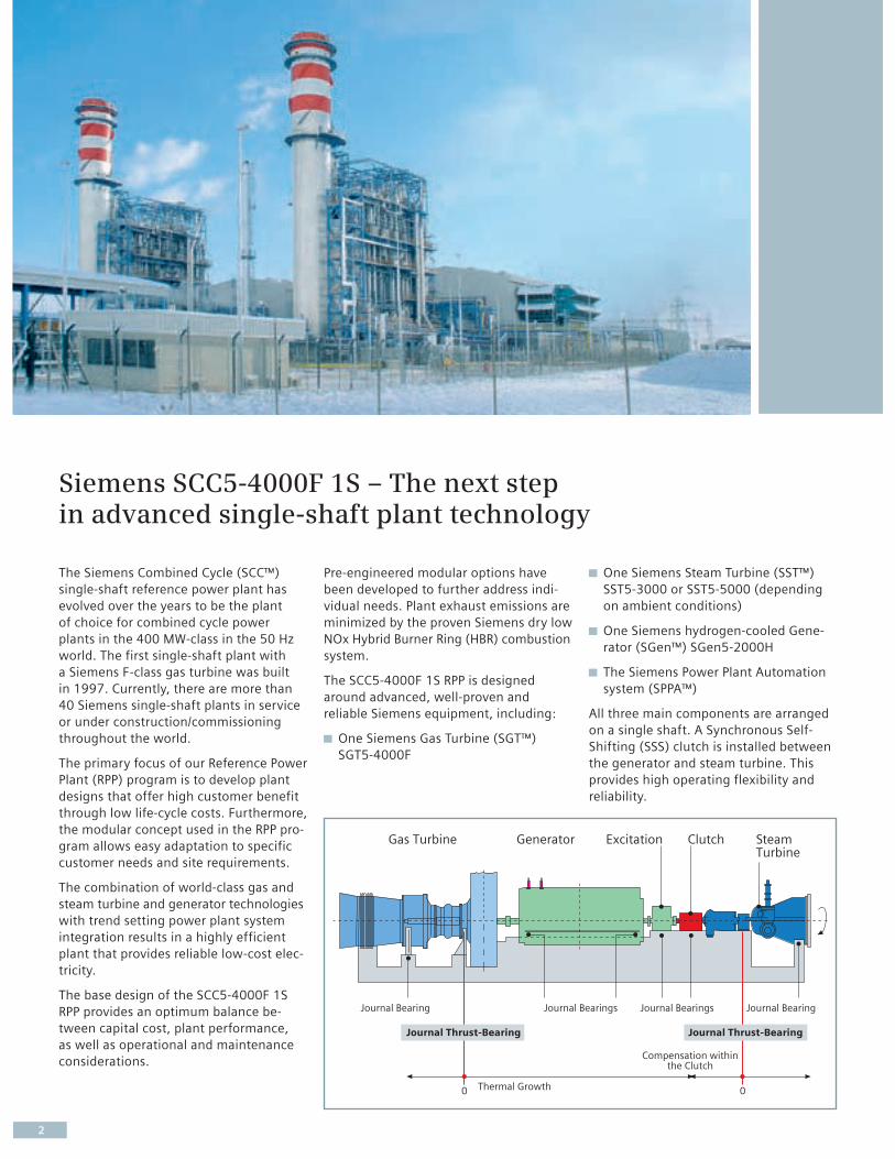
The Siemens Combined Cycle (SCC™)
single-shaft reference power plant has
evolved over the years to be the plant
of choice for combined cycle power
plants in the 400 MW-class in the 50 Hz
world. The first single-shaft plant with
a Siemens F-class gas turbine was built
in 1997. Currently, there are more than
40 Siemens single-shaft plants in service
or under construction/commissioning
throughout the world.
The primary focus of our Reference Power
Plant (RPP) program is to develop plant
designs that offer high customer benefit
through low life-cycle costs. Furthermore,
the modular concept used in the RPP pro-
gram allows easy adaptation to specific
customer needs and site requirements.
The combination of world-class gas and
steam turbine and generator technologies
with trend setting power plant system
integration results in a highly efficient
plant that provides reliable low-cost elec-
tricity.
The base design of the SCC5-4000F 1S
RPP provides an optimum balance be-
tween capital cost, plant performance,
as well as operational and maintenance
considerations.
Pre-engineered modular options have
been developed to further address indi-
vidual needs. Plant exhaust emissions are
minimized by the proven Siemens dry low
NOx Hybrid Burner Ring (HBR) combustion
system.
The SCC5-4000F 1S RPP is designed
around advanced, well-proven and
reliable Siemens equipment, including:
One Siemens Gas Turbine (SGT™)
SGT5-4000F
Siemens SCC5-4000F 1S – The next step in advanced single-shaft plant technology
One Siemens Steam Turbine (SST™)
SST5-3000 or SST5-5000 (depending
on ambient conditions)
One Siemens hydrogen-cooled Gene-
rator (SGen™) SGen5-2000H
The Siemens Power Plant Automation
system (SPPA™)
All three main components are arranged
on a single shaft. A Synchronous Self-
Shifting (SSS) clutch is installed between
the generator and steam turbine. This
provides high operating flexibility and
reliability.
Project Specificbased on “clean sheet”
Reference Power Plantbased on multiple modules
Standardized Power Block
3
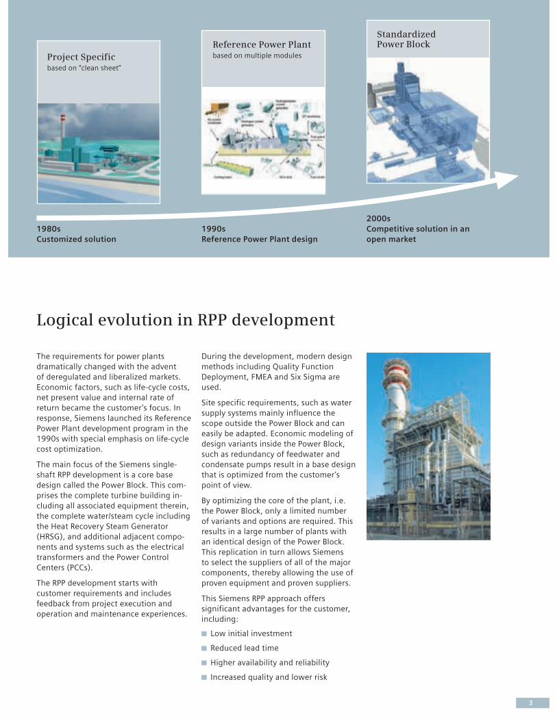
The requirements for power plants
dramatically changed with the advent
of deregulated and liberalized markets.
Economic factors, such as life-cycle costs,
net present value and internal rate of
return became the customer’s focus. In
response, Siemens launched its Reference
Power Plant development program in the
1990s with special emphasis on life-cycle
cost optimization.
The main focus of the Siemens single-
shaft RPP development is a core base
design called the Power Block. This com-
prises the complete turbine building in-
cluding all associated equipment therein,
the complete water/steam cycle including
the Heat Recovery Steam Generator
(HRSG), and additional adjacent compo-
nents and systems such as the electrical
transformers and the Power Control
Centers (PCCs).
The RPP development starts with
customer requirements and includes
feedback from project execution and
operation and maintenance experiences.
During the development, modern design
methods including Quality Function
Deployment, FMEA and Six Sigma are
used.
Site specific requirements, such as water
supply systems mainly influence the
scope outside the Power Block and can
easily be adapted. Economic modeling of
design variants inside the Power Block,
such as redundancy of feedwater and
condensate pumps result in a base design
that is optimized from the customer’s
point of view.
By optimizing the core of the plant, i.e.
the Power Block, only a limited number
of variants and options are required. This
results in a large number of plants with
an identical design of the Power Block.
This replication in turn allows Siemens
to select the suppliers of all of the major
components, thereby allowing the use of
proven equipment and proven suppliers.
This Siemens RPP approach offers
significant advantages for the customer,
including:
Low initial investment
Reduced lead time
Higher availability and reliability
Increased quality and lower risk
Logical evolution in RPP development
1980s
Customized solution
1990s
Reference Power Plant design
2000s
Competitive solution in an
open market
4
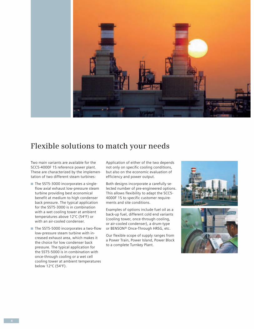
Two main variants are available for the
SCC5-4000F 1S reference power plant.
These are characterized by the implemen-
tation of two different steam turbines:
The SST5-3000 incorporates a single-
flow axial exhaust low-pressure steam
turbine providing best economical
benefit at medium to high condenser
back pressure. The typical application
for the SST5-3000 is in combination
with a wet cooling tower at ambient
temperatures above 12°C (54°F) or
with an air-cooled condenser.
The SST5-5000 incorporates a two-flow
low-pressure steam turbine with in-
creased exhaust area, which makes it
the choice for low condenser back
pressure. The typical application for
the SST5-5000 is in combination with
once-through cooling or a wet cell
cooling tower at ambient temperatures
below 12°C (54°F).
Application of either of the two depends
not only on specific cooling conditions,
but also on the economic evaluation of
efficiency and power output.
Both designs incorporate a carefully se-
lected number of pre-engineered options.
This allows flexibility to adapt the SCC5-
4000F 1S to specific customer require-
ments and site conditions.
Examples of options include fuel oil as a
back-up fuel, different cold end variants
(cooling tower, once-through cooling,
or air-cooled condenser), a drum-type
or BENSON® Once-Through HRSG, etc.
Our flexible scope of supply ranges from
a Power Train, Power Island, Power Block
to a complete Turnkey Plant.
Flexible solutions to match your needs

5
Scope of supply
SCC Power Train
SGT-PAC
SCC Power Island
SCC Power Train
SCC Power Block
SCC Power Island
SCC Turnkey
SCC Power Block
Power Train equipment
Performance/Delivery
System integration/
Optimized operability
Replication of standardized
components
Total EPC plant wrap
• HRSG
• Condenser incl. airremoval system
• Boiler feed pumps
• Condensate pumps
• Critical valves
• Fuel pre-heater with filter,metering station etc.
• Power Island controls
• Options
• SST-PAC w/o condenser
– Steam turbine incl.auxiliaries w/o piping
– Generatorincl. auxiliaries
– SSS Clutch
– ST electrical and I&C
• Options
• Detailed design of turbine buil-ding, foundation and structures
• HVAC inside Power Block area
• Cranes inside turbine building
• Water/steam cycle
• Cooling water system withwet cooling tower and circulatingwater pumps
• Service- and closed cooling watersystem
• Electrical equipment
• Power Block controls
• Fire fighting inside Power Block
• Options
• Additional fuel supply systemsand cooling systems
• Water treatment
• Raw water system
• Waste water system
• Tanks
• Additional– Buildings/structures– Cranes/hoists– Fire protection/fighting– Plant piping/valves– Electrical plant
• Erection/Commissioning
• Further options

6
The main building is a compact structural-
steel building of rectangular design and
houses the gas turbine, generator and
steam turbine along with their associated
components.
The main gas turbine auxiliaries are
arranged on a steel platform along side
the gas turbine. The common lube oil
system for gas turbine, generator and
steam turbine is arranged at ground
floor level.
All generator auxiliaries are directly
arranged next to the generator either
on the main steel platform or on the
ground floor.
The auxiliary components for the water/
steam cycle and the closed cooling water
system are located in an annex to the
t urbine building. The air-intake filter
house is located above the annex at the
side of the main bay of the turbine build-
ing. The filtered air is led straight into
the gas turbine compressor by way of
an aerodynamically optimized oblique
steel-fabricated duct, in which a silencer
is installed.
Access to the building is provided via the
entrance bay next to the turbine-genera-
tor set. Adequate access for inspection
and maintenance is provided for all main
and auxiliary equipment.
An overhead traveling crane runs the
full length of the turbine building and is
capable to lift all the heavy equipment
in the building including the generator.
Special attention has been given to pro-
vide short moving distances and adequate
dismantling and laydown areas for major
maintenance operations, as well as good
accessibility to buildings and components
for maintenance.
The HRSG as well as the annexed feed-
water pumps are designed for outdoor
installation.
The pre-fabricated and pre-tested Power
Control Centers (PCCs) for electrical and
I&C equipment are located outdoors close
to the turbine buildings to ensure short
connection runs.
The central control room and administra-
tion building are arranged close to the
turbine building. Layout provisions are
made in the plant for a workshop and
storage building.
Plant layout
A forced-draft cooling tower is arranged
behind the turbine building with the
circulating water pump also in outdoor
installation. In case of once-through
cooling, the water intake and outfall
structure is designed according to site
requirements.
Site terminal points
The SCC5-4000F 1S base design incor-
porates the following terminal point
assumptions:
Natural gas fuel supply at required
conditions at the site boundary
Raw, fire fighting and potable water
from municipal supply at required
conditions at site boundary
Demineralized water tank hook up
Effluent discharge to municipal
connection at site boundary
Electrical termination at high-voltage
bushing of the generator step-up
transformer

Fuel oil unloadingand forwarding
Fuel oil tank
Control roomand administrationbuilding
Feedwater pump
Wo
rksh
op
an
dst
ora
ge
bu
ild
ing
HRSG
Deminwater plant
Power ControlCenter (PCC)
Coolingtower
Turbinebuilding
Tra
nsf
orm
er
250 m
20
0 m
50
m
125 m
7
Plot plan SCC5-4000F single-shaft with oil tank and cooling tower
Plant arrangement
8
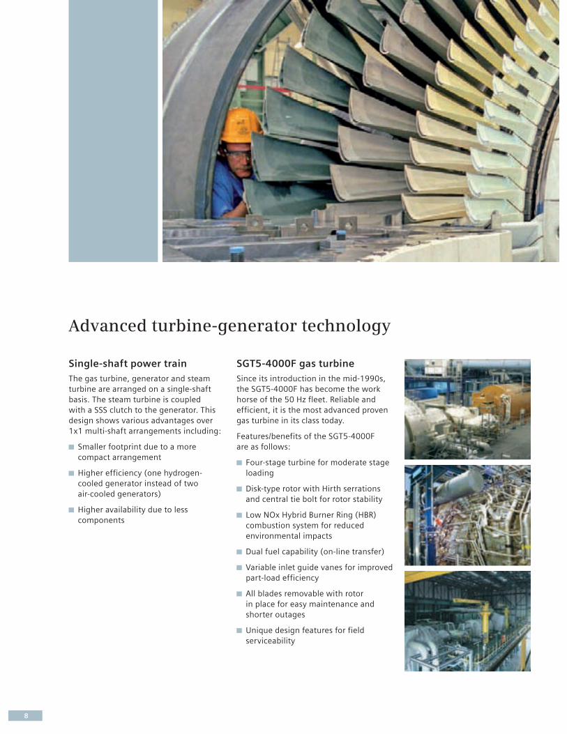
Single-shaft power train
The gas turbine, generator and steam
turbine are arranged on a single-shaft
basis. The steam turbine is coupled
with a SSS clutch to the generator. This
design shows various advantages over
1x1 multi-shaft arrangements including:
Smaller footprint due to a more
compact arrangement
Higher efficiency (one hydrogen-
cooled generator instead of two
air-cooled generators)
Higher availability due to less
com ponents
SGT5-4000F gas turbine
Since its introduction in the mid-1990s,
the SGT5-4000F has become the work
horse of the 50 Hz fleet. Reliable and
efficient, it is the most advanced proven
gas turbine in its class today.
Features/benefits of the SGT5-4000F
are as follows:
Four-stage turbine for moderate stage
loading
Disk-type rotor with Hirth serrations
and central tie bolt for rotor stability
Low NOx Hybrid Burner Ring (HBR)
combustion system for reduced
environmental impacts
Dual fuel capability (on-line transfer)
Variable inlet guide vanes for improved
part-load efficiency
All blades removable with rotor
in place for easy maintenance and
shorter outages
Unique design features for field
serviceability
Advanced turbine-generator technology

9
SST5-3000 steam turbine
The SST5-3000 steam turbine comprises
a single-flow barrel-type high-pressure
turbine and a combined intermediate-
and low-pressure turbine element with
single-flow axial exhaust. This turbine is
mainly applied for wet cooling tower or
air-cooled condenser operation.
SST5-5000 steam turbine
The SST5-5000 steam turbine comprises
a combined high- and intermediate-
pressure turbine element and a two-flow
low-pressure turbine with a single-side
exhaust. The larger exhaust area provid-
ed with this low pressure steam turbine
enables better performance at sites with
access to cold cooling water.
SGen5-2000H generator
The SGen5-2000H is a hydrogen-cooled
two-pole generator. This well-proven
generator design provides high efficiency
and low operation and maintenance costs.
It is shipped to the site pre-assembled to
facilitate ease of construction.
SSS clutch
A Synchronous Self-Shifting (SSS) clutch
is located between the generator and
the steam turbine. This allows individual
gas turbine start-up without the need
for cooling the steam turbine. Once the
steam parameters match the require-
ments of the turbine, the steam turbine
turns and synchronizes automatically
with the generator. The SSS clutch has
been used successfully since 1995 in
numerous Siemens single shaft power
plants.

Boundary
Grid frequency
Ambient temperature
Site elevation
Fuel
Steam parameter
50 Hz
-20°C to 40°C (-5°F to 105°F)(15°C/59°F design for SST5-3000, 10°C/50°F design for SST5-5000)
Design 0 m
Main fuel: Natural gas, LHV: 50,012 kJ/kg(Methane at ISO conditions: 21,502 Btu/lbm)
Back-up fuel: Fuel oil Cat.II, LHV: 42,600 kJ/kg/18,315 Btu/lbm
565°C/125 bar (1,050°F/1,815 psi)565°C/30 bar (1,050°F/435 psi)235°C/5 bar (455°F/75 psi)
SCC5-4000F 1S RPP design base
10
Water/steam cycle and cooling system
To provide high efficiency a triple-pressure
reheat cycle is used. The plant design
includes options for both a drum-type and
a BENSON® Once-Through HRSG.
The BENSON® HRSG, designed and patent-
ed by Siemens, provides greatly improved
operating flexibility with faster start-up
and load change capability. Condensate
and feedwater pumps are arranged in a
booster set-up for low power consump-
tion. Both main pumps are configured as
2x100% pumps for high availability.
The base design contains a wet cell cool-
ing tower. Available options for cooling
include an air-cooled condenser or once-
through cooling.
Plant auxiliaries are directly cooled by
means of a closed cooling water system
using heat exchangers.
Plant design base and performance data
The SCC5-4000F 1S is designed with the following conditions:

Performance
423 MW (ISO ambient conditions,reference design)
58.4% (ISO ambient conditions,reference design)
6,164 kJ/kWh(5,842 Btu/kWh)
Main fuel: ≤ 25 ppmvd(Base load)
Main fuel: ≤ 10 ppmvd(Base load)
342.1 kg CO2/MWel
(Natural gas)
SCC5-4000F 1S (SST5-3000)* SCC5-4000F 1S (SST5-5000)**
434 MW (10°C/50°F ambienttemperature, once-through cooling)
58.9% (10°C/50°F ambient temper-ature, once-through cooling)
6,112 kJ/kWh(5,793 Btu/kWh)
Main fuel: ≤ 25 ppmvd(Base load)
Main fuel: ≤ 10 ppmvd(Base load)
339.2 kg CO2/MWel
(Natural gas)
Net plant poweroutput Pnet
Net plant powerefficiencyηnet
Net plant heatrate
Plant NOx
emissions
Plant COemissions
Plant CO2
emissions
Project and site-specific performance data for this and other Siemens combined cycle products can be obtained through SIPEP, the Siemens Plant Performance Estimation Program. For access to SIPEP please contact your Siemens sales representative.
* Standard design; ISO ambient conditions** 10°C/50°F ambient temperature, once-through cooling
11
The advanced Siemens SCC5-4000F 1S
The Siemens SCC5-4000F 1S is a new
milestone in the sector of 400 MW-class
50 Hz combined cycle plants. Not only is
it one of the most powerful and efficient
F-class plants on the market today, but
even more important it is the most envi-
ronmentally friendly with its significant
reduction in emissions and water con-
sumption. It builds on years of experience
and includes feedback from executed
projects. Additionally, it incorporates the
feedback of customer interviews and QFD
workshops to include the latest market
developments. It is the answer to meet
any 50 Hz combined cycle power plant
needs in the future.
The use of our world-class gas turbine,
steam turbine and generator technology
combined with our expertise to design
and build world-class combined cycle
power plants helps to ensure that your
plant will remain a sound investment for
many years to come.
With the mentioned boundary conditions the following performance is achieved:
Published by and copyright © 2008:Siemens AGEnergy SectorFreyeslebenstrasse 191058 Erlangen, Germany
Siemens Power Generation, Inc.4400 Alafaya TrailOrlando, FL 32826-2399, USA
For more information, contact our Customer Support Center.Phone: +49 180/524 70 00Fax: +49 180/524 24 71(Charges depending on provider)e-mail: [email protected]
Fossil Power Generation DivisionOrder No. A96001-S90-B327-X-4A00Printed in GermanyDispo 05400, c4bs No. 1353, 799108409M WS 05083.
Printed on elementary chlorine-free bleached paper.
All rights reserved.Trademarks mentioned in this document are the property of Siemens AG, its affi liates, or their respective owners.
Subject to change without prior notice.The information in this document contains general descriptions of the technical options available, which may not apply in all cases. The required technical options should therefore be specifi ed in the contract.
www.siemens.com/energy

Annexure-7
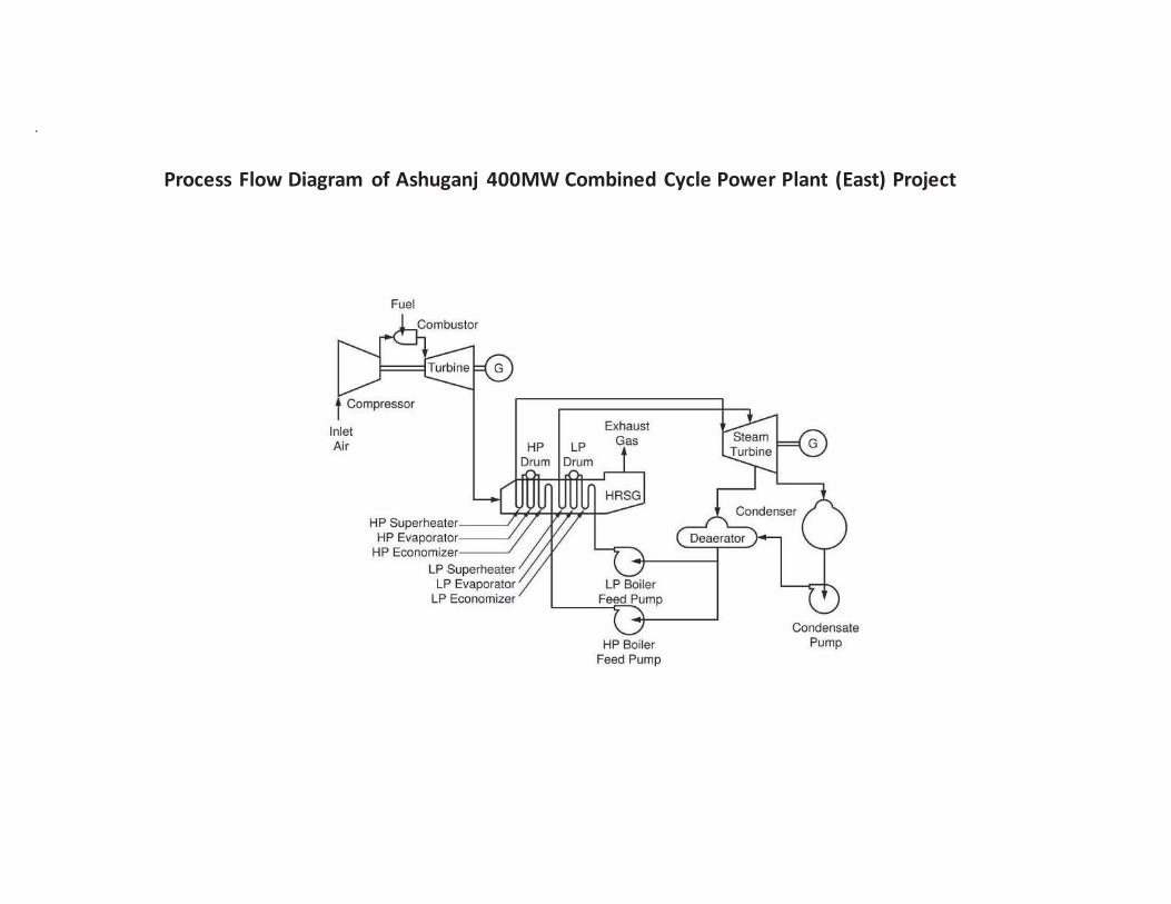
Process Flow Diagram
.
Process Flow Diagram of Ashuganj 400MW Combined Cycle Power Plant (East) Project
Annexure-8
Layout Plan for Cooling
Water Discharge
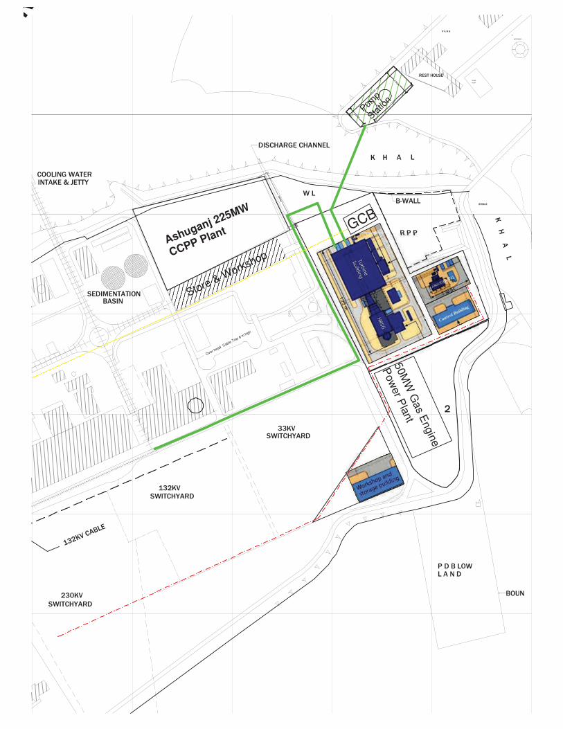
Over head C
able Tray 6 m high
Pump
Statio
n
Ashuganj 225MW
CCPP Plant
Store & Workshop
50M
W G
as E
ngin
e
Pow
er P
lant
GCB

Annexure-9 (a)
Surface Water Temperature at
Different Locations of Meghna
River
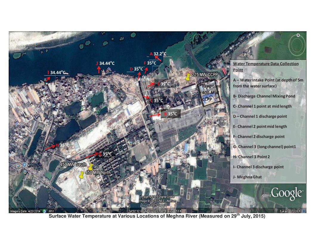
Surface Water Temperature at Various Locations of Meghna River (Measured on 29th July, 2015)
B 35oC
C 35oC C 35
G 35oC
H 35oC
E 35oC
D 35oC
A 32.2oC
C
F 35oC
I 34.44oC
J 34.44oC Water Temperature Data Collection
Point
A Water Intake Point (at depth of 5m
from the water surface)
B- Discharge Channel Mixing Pond
C- Channel 1 point at mid length
D Channel 1 discharge point
E- Channel 2 point mid length
F- Channel 2 discharge point
G- Channel 3 (long channel) point1
H- Channel 3 Point 2
I- Channel 3 discharge point
J- Meghna Ghat
Proposed
400 MW
CCPP

Annexure-9 (b)
Waste Water Treatment
Plant
AAAAAAAAAAAAAAAAAAAAAAAAAAAAAAAAAAAAAAAAAAAAAAAAAAAAAAAAAAAAAAAAAAAAAAAAAAAAAAAAAAAAAAAAAAAAAAAAAAAAAAAAAAAAAAAAAAAAAAAAAAAAAAAAAAAAnnnnnnnnnnnnnnnnnnnnnnnnnnnnnnnnnnnnnnnnnnnnnnnnnnnnnnnnnnnnnnnnnnnnnnnnnnnnnnnnnnnnnneeeeeeeeeeeeeeeeeeeeeeeeeeeeeeeexxxxxxxxxxxxxxxxxxxxxxxxxxxxxxxxxxxxxxxxxxxuuuuuuuuuuuuuuuuuuuuuuuuuuuuuuuuuuuurrrrrrrrrrrrrrrrrrrrrrrrrrrrrrrrrrrrrrrrrrrrrrrrrrreeeeeeeeeeeeeeeeeeeeeeeeeeeeeeeeee-------999999999999999999999999999999999999999999999999999999999999999999999999999999999999999999999999999999999999999999999999 (((((((((((((((((((((((((((((((((((((((((((((((((((((((((((((((((((((((((((((((((((((((((((((((((((((((((((((((((((((((((((((((((((((((((((((((((((((((((((((((((((((((((((((((bbbbbbbbbbbbbbbbbbbbbbbbbbbbbbbbbbbbbbbbbbbbbbbbbbbbbbbbbbbbbbbbbbbbbbbbbbbbbbbbbbbbbbbbbbbbbbbbbbbbbbbbbbbbbbbbbbbbbbbbbbbbbbbbbbbbbbbbb)))))))))))))))))))))))))))))))))))))))))))))))))))))))))))))))))))))))))))))))))))))))))))))))))))))))))))))))))))))))))))))))
WWWWWWWWWWWWWWWWWWWWWWWWWWWWWWWWWWWWWWWWWWWWWWWWWWWWWWWWWWWWWWWWWWWWWWWWWWWWWWWWWWWWWWWWWWWWWWWWWWWWWWWWWWWWWWWWWWWWWWWWWWWWWWWWWWWWWWWWWWWWWWWWWWWWWWWWWWWWWWWWWWWWWWWWWWWWWWWWWWWWWWWWWWWWWWWWWWWWWWWWWWWWWWWWWWWWWWWWWWWWWWWWWWWWWWWWWWWWWWWWWWWWWWWWWWWWWWWWWWWWWWWWWWWWWWWWWWWWWWWWWWWWWWWWWWWWWWWWWWWWWWWWWWWWWWWWWWWWWWWWWWWWWWWWWWWWWWWWWWWWWWWWWWWWWWWWWWWWWWaaaaaaaaaaaaaaaaaaaaaaaaaaaaaaaaaaaaaaaaaaaaaaaaaaaaaaaaaaaaaaaaaaaaaaaaaaaaaaaaaaaaaaaaaaaaaaaaaaaaaaaaaaaaaaaaaaaaaaaaaaaaaaaaaaaaaaaaaaaaaaaaaaaaaaaaaaaaaaaaaaaaaaaaaaaaaaaaaaaaaaaaaaaaaaaaaaaaaaaaaaaaaaaaaaaaaaaaaaaaaaaaaaaaaaaaaaaaaaaaaaaaaaaaaaaaaaaaaaaaaaaaaaaaaaaaaaaaaaaaaaaaaaaaaaaaaaaaaaaaaaaaaaaaaaaaaaaaaaaaaaaaaaaaaaaaaaaaaassssssssssssssssssssssssssssssssssssssssssssssssssssssssssssssssssssssssssssssssssssssssssssssssssssssssssssssssssssssssssssssssssssssssssssssssssssssssssssssssssssssssssssssssssssssssssssssssssssssssssssssssssssssssssssssssssssssssssstttttttttttttttttttttttttttttttttttttttttttttttttttttttttttttttttttttttttttttttttttttttttttttttttttttttttttttttttttttttttttttttttttttttttttttttttttttttttttttttttttttttttttttttttttttttttttttttttttttttttttttttttttttttttttttttttttttteeeeeeeeeeeeeeeeeeeeeeeeeeeeeeeeeeeeeeeeeeeeeeeeeeeeeeeeeeeeeeeeeeeeeeeeeeeeeeeeeeeeeeeeeeeeeeeeeeeeeeeeeeeeeeeeeeeeeeeeeeeeeeeeeeeeeeeeeeeeeeeeeeeeeeeeeeeeeeeeeeeeeeeeeeeeeeeeeeeeeeeeeeeeeeeeeeeeeeeeeeeeeeeeeeeeeeeeeeeeeeeeeeeeeeeeeeeeeeeeeeeeeeeeeeeeeeeeeeeeeeeee WWWWWWWWWWWWWWWWWWWWWWWWWWWWWWWWWWWWWWWWWWWWWWWWWWWWWWWWWWWWWWWWWWWWWWWWWWWWWWWWWWWWWWWWWWWWWWWWWWWWWWWWWWWWWWWWWWWWWWWWWWWWWWWWWWWWWWWWWWWWWWWWWWWWWWWWWWWWWWWWWWWWWWWWWWWWWWWWWWWWWWWWWWWWWWWWWWWWWWWWWWWWWWWWWWWWWWWWWWWWWWWWaaaaaaaaaaaaaaaaaaaaaaaaaaaaaaaaaaaaaaaaaaaaaaaaaaaaaaaaaaaaaaaaaaaaaaaaaaaaaaaaaaaaaaaaaaaaaaaaaaaaaaaaaaaaaaaaaaaaaaaaaaaaaaaaaaaaaaaaaaaaaaaaaaaaaaaaaaaaaaaaaaaaaaaaaaaaaaaaaaaaaaaaaaaaaaaaaaaaaaaaaaaaaaaaaaaaaaaaaaaaaaaaaaaaaaaaaaaaaaaaaaaaaaaaaaaaaaaaaaaaaaaaaaaaaaaaaaaaaaaaaaaaaaaaaaaaaaaaaaaaaaaaaaaaaaaaaaaaaaaaaaaaaaaaaaaaaaaaaaaaaaaattttttttttttttttttttttttttttttttttttttttttttttttttttttttttttttttttttttttttttttttttttttttttttttttttttttttttttttttttttttttttttttttttttttttttttttttttttttttttttttttttttttttttttttttttttttttttttttttttttttttttttttttttttttttttttttttttttttttttttttttttttttttttttteeeeeeeeeeeeeeeeeeeeeeeeeeeeeeeeeeeeeeeeeeeeeeeeeeeeeeeeeeeeeeeeeeeeeeeeeeeeeeeeeeeeeeeeeeeeeeeeeeeeeeeeeeeeeeeeeeeeeeeeeeeeeeeeeeeeeeeeeeeeeeeeeeeeeeeeeeeeeeeerrrrrrrrrrrrrrrrrrrrrrrrrrrrrrrrrrrrrrrrrrrrrrrrrrrrrrrrrrrrrrrrrrrrrrrrrrrrrrrrrrrrrrrrrrrrrrrrrrrrrrrrrrrrrrrrrrrrrrrrrrrrrrrrrrrrrrrrrrrrrrrrrrrrrrrrrrrrrrrrrrrrrrrrrrrrrrrrrrrrrrrrrrrrrrrrrrrrrrrrrrrrrrrrrrrrrrrrr TTTTTTTTTTTTTTTTTTTTTTTTTTTTTTTTTTTTTTTTTTTTTTTTTTTTTTTTTTTTTTTTTTTTTTTTTTTTTTTTTTTTTTTTTTTTTTTTTTTTTTTTTTTTTTTTTTTTTTTTTTTTTTTTTTTTTTTTTTTTTTTTTTTTTTTTTTTTTTTTTTTTTTTTTTTTTTTTTTTTTTTTTTTTTTTTTTTTTTTTTTTTTTTTTTTTTTTTTTTTTTTTTTTTTTTTTTTTTTTTTTTTTTTTTTTTTTTTTTTTTTTTTTTTTTTTTTTTTTTTTTTTTTTTTTTTTTTTTTTTTTTTTTTTTTTTTTTTTTTTTTTTTTTTTTTTTTTTTTTTTTTTTTTTTTTTTTTTTTTTTTTTTTTTrrrrrrrrrrrrrrrrrrrrrrrrrrrrrrrrrrrrrrrrrrrrrrrrrrrrrrrrrrrrrrrrrrrrrrrrrrrrrrrrrrrrrrrrrrrrrrrrrrrrrrrrrrrrrrrrrrrrrrrrrrrrrrrrrrrrrrrrrrrrrrrrrrrrrrrrrrrrrrrrrrrrrrrrrrrrrrrrrrrrrrrrrrrrrrrrrrrrrrrrrrrrrrrrrrrrrrrrrrrrrrrrrrrrrrrrrrrrrrrrrrrrrrrrrrrrreeeeeeeeeeeeeeeeeeeeeeeeeeeeeeeeeeeeeeeeeeeeeeeeeeeeeeeeeeeeeeeeeeeeeeeeeeeeeeeeeeeeeeeeeeeeeeeeeeeeeeeeeeeeeeeeeeeeeeeeeeeeeeeeeeeeeeeeeeeeeeeeeeeeeeeeeeeeeeeeeeeeeeeeeeeeeeeeeeeeeeeeeeeeeaaaaaaaaaaaaaaaaaaaaaaaaaaaaaaaaaaaaaaaaaaaaaaaaaaaaaaaaaaaaaaaaaaaaaaaaaaaaaaaaaaaaaaaaaaaaaaaaaaaaaaaaaaaaaaaaaaaaaaaaaaaaaaaaaaaaaaaaaaaaaaaaaaaaaaaaaaaaaaaaaaaaaaaaaaaaaaaaaaaaaaaaaaaaaaaaattttttttttttttttttttttttttttttttttttttttttttttttttttttttttttttttttttttttttttttttttttttttttttttttttttttttttmmmmmmmmmmmmmmmmmmmmmmmmmmmmmmmmmmmmmmmmmmmmmmmmmmmmmmmmmmmmmmmmmmmmmmmmmmmmmmmmmmmmmmmmmmmmmmmmmmmmmmmmmmmmmmmmmmmmmmmmmmmmmmmmmmmmmmmmmmmmmmmmmmmmmmmmmmmmmmmmmmmmmmmmmmmmmmmmmmmmmmmmmmmmmmmmmmmmmmmmmmmmmmmmmmmmmmmmmmmmmmmmmmmmmmmmmmmmmmmmmmmmmmmmmmmmmmmmmmmmmmmmmmmmmmmmmmmmmmmmmmmmmmmmmmmmmmmmmmmmmmmmmmmmmmmmmmmmmmmmmmmmmmmmmmmmmmmmmmmmmmmmmmmmmmmmmmmmmmmmmmmmmmmmmmmmmmmmmmmmmmmmmmmmmmmmmmmmmmmmmmmmmmmmmmmmmmmmmmmmmmmmmmmmmmmmmmmmmmmmmmmmmmmmmmmmmmmmeeeeeeeeeeeeeeeeeeeeeeeeeeeeeeeeeeeeeeeeeeeeeeeeeeeeeeeeeeeeeeeeeeeeeeeeeeeeeeeeeeeeeeeeeeeeeeeeeeeeeeeeeeeeeeeeeeeeeeeeeeeeeeeeeeeeeeeeeeeeeeeeeeeeeeeeeeeeeeeeeeeeeeeeeeeeeeeeeeeeeeeeeeeeeeeeeeeeeeeeeeeeeeeeeeeeeeeeeeeeeeeeeeeeeeeeeeeeeeeeeeeeeeeeeeeeeeeeeeeeeeeeeeeeeeeeeeennnnnnnnnnnnnnnnnnnnnnnnnnnnnnnnnnnnnnnnnnnnnnnnnnnnnnnnnnnnnnnnnnnnnnnnnnnnnnnnnnnnnnnnnnnnnnnnnnnnnnnnnnnnnnnnnnnnnnnnnnnnnnnnnnnnnnnnnnnnnnnnnnnnnnnnnnnnnnnnnnnnnnnnnnnnnnnnnnnnnnnnnnnnnnnnnnnnnnnnnnnnnnnnnnnnnnnnnnnnnnnnnnnnnnnnnnnnnnnnnnnnnnnnnnnnnnnnnnnnnnnnnnnnnnnnnnnnnnnnnnnnnnnnnnnnnnnnnnnntttttttttttttttttttttttttttttttttttttttttttttttttttttttttttttttttttttttttttttttttttttttttttttttttttttttttttttttttttttttttttttttttttttttttttttttttttttttttttttttttttttttttttttttttt
PPPPllllaaaannnntttt

Meg
hn
a R
iver
Su
rface W
ate
r
Open Circuit
Condensate Cooling in
Condenser
Intake 28500 m3/hr
ST
Existing
Drinking water
Plant
11 m3/hr
Condensate
makeup 6 m3/hr
Closed loop cooling
water Circuit
Service Water
for Office use Septic Tank
DM Water Plant
of 225MW
Co
nd
en
sa
te
40
0 m
3/h
r
WWTP 2.0 m3/hr
2000 m3/hr Discharge
Waste
wate
r fr
om
do
mesti
c u
se
Floor Runoff Oil Interceptor
Makeup
5 m3/hr
Open Circuit of Closed
cooling water Heat
Exchanger
202000 m /hr Discharge
Intake 2000 m3/hr
CIntake26500 m3/hr
Cooling
water
1200
m3/hr
Cooling
water
1195
m3/hr
Condensate
394 m3/hr
2 m3/hr
0.5 m3/hr
0.5 m3/hr