environmental condition control and energy management system
TRANSCRIPT

US006216956B1
United States Patent (12) (10) Patent N0.: US 6,216,956 B1 Ehlers et al. (45) Date of Patent: *Apr. 17, 2001
(54) ENVIRONMENTAL CONDITION CONTROL 0288413 A1 10/1988 (EP) .......................... .. G01B/21/133 AND ENERGY MANAGEMENT SYSTEM 0534839 A1 3/1993 (EP) ........... .. H05B/37/03 .......... ..
AND METHOD (List continued on next page.)
(75) Inventors: Gregory A. Ehlers, Tampa; Richard OTHER PUBLICATIONS M. Silva, St. Petersburg, both of FL _ _ _ (Us) “MicroSmart Control Network System Overview”, Siebe
Environmental Controls, Nov. 1993, pp. 1—12. (73) Assignee: Tocom, Inc., FoXboro, MA (US) “MicroSmart Control Network (Features and Bene?ts)”, * _ _ _ _ _ Siebe Environmental Controls, 1993, 10 pages.
( ) Notice: SubJect to any d1scla1mer,~the term of this “Microsmart MSC_NC/NCM (Network Communications Patent 15 extended or adlusted under 35 Module) Installation Guidelines”, Siebe Environmental U'S'C' 154(k)) by 0 days‘ Controls, Jun. 1993, pp. 1—9.
_ _ _ _ _ “MSC—NC(M) MicroSmart NetWork Communications
Tlhl_s Patent 15 Sublect to a termmal (115' Module”, Siebe Environmental Controls, Jul. 1993, 2 pages. c a1mer.
(List continued on neXt page.) (21) Appl.No.: 09/220,129 _ _ _ _
_ Primary Exammer—W1ll1am Wayner (22) Flled: Dec- 23’ 1998 (74) Attorney, Agent, or Firm—Wolf, Green?eld & Sacks,
Related US. Application Data PC‘
(57) ABSTRACT (63) Continuation of application No. 08/960,748, ?led on Oct.
29, 1997, HOW Pat- N0~ 5,924,486 An indoor environmental condition control and energy man agement system includes a plurality of inputs. Auser input
(51) Int. Cl.7 ............................ .. G05D 23/00; H02V 1/00 receives user input parameters including a desired indoor environmental condition range for at least one energy unit
U-S- Cl- ........................... .. price point An indoor environmental Condition input receives a sensed indoor environmental condition. An
(58) Field Of Search ................................... .. 236/94, 78 R, energy price input receives a Schedule of projected energy 236/46 R 47; 165/241> 242> 255; 364/528~11> unit prices per time periods. A processor, coupled to the
528-35; 307/39 inputs, computes an environmental condition deadband (56) References Cited range for multiple energy unit price points based on the user
input parameters and controls at least one energy-consuming U-S- PATENT DOCUMENTS load device to maintain the indoor environmental condition
175477242 * 7/1925 Strieby ' Within the computed deadband range for a then-current 4,075,699 * 2/1978 Schneider et al. ................. .. 364/492 energy 11991)?“ Pomt- In an embodlmenh the envlronmen' 471747517 4 11/1979 Mandel ________ __ tal condition mcludes at least temperature and the at least 4,217,646 * 8/1980 Caltagirone et al. .............. .. 165/238 one load device includes a heating and Cooling system The
. . processor, in one embodiment, communicates through a (Llst Con?rmed on next page‘) communications link With at least one energy supply com
FOREIGN PATENT DOCUMENTS pany and selects one energy supply company for a premise
2121124 7/1993 (CA) ........................... .. G05D/23/19 to minimize energy Consumption Cost‘
27 43 212 3/1979 (DE) .. H02J/13/0O 0163572 12/1985 (EP) ............................. .. H02J/13/00 7 Claims, 6 Drawing Sheets
INPUT 1O INPUT 20 STORAGE 30 PROCESS 40 OUTPUT OUTPUT DEVICES FUNCTIONS FUNCTIONS FUNCTIONS FUNCTIONS DEVICES
J L2 ENERGY KEYPAD —> COST
INPUTS TIME
<——> KEEPING 53
PROCESS 33 DISPLAY 58 DATA AUDIO / COLLECTION -__> USER 34 43 a STORAGE REPORTING USER
21 PROCESS OUTPUT 14 / INTERFACE
W usER DATA & INQUIRY INPUTS
' 15 3S 51 ~ ~—- TEMP TEMPERATURE '“
SENS/2R E DECISEORQEJRE CONTROL T4 CONTACTS
INPUTS

US 6,216,956 B1 Page 2
US. PATENT DOCUMENTS FOREIGN PATENT DOCUMENTS
4,218,737 * 8/1980 Buscher et al. .................... .. 364/493 0577532 A1 1/1994 (EP) ............................... .. H02J/3/14
4,245,319 * 1/1981 Hedges ...... .. . 364/492 0580217 A1 1/1994 (EP) H02J/3/14 4,291,375 * 9/1981 Wolf ............. .. . 364/483 0688 085 A1 12/1995 (EP) H02J/13/00
4,324,987 * 4/1982 Sullivan, II et al. 307/35 2645968 A1 10/1990 (FR) G01R/19/12 4,336,462 * 6/1982 Hedges et al. . . . . . . . . . .. 307/35 2660511 A1 10/1991 (FR) .. H04Q/9/02
4,338,791 * 7/1982 Stamp, Jr. et al. 165/242 X WO93/08653 4/1993 (WO) . .. H04B/3/56 4,367,414 * 1/1983 Miller et al. .... .. 307/38 4,382,544 * 5/1983 Stewart ..... .. . 165/328 OTHER PUBLICATIONS
4,466,074 * 8/1984 Jindrick et al. .................... .. 364/145 4,475,193 * 10/1984 Brown ................................ .. 370/124 “MSC—MPC—100 MSC—MPC—RC MSC—MPC—RCM
4,503,188 * 3/1985 Kessler __ 179/2 DP MicroSmart Multi—Purpose Controllers”, Siebe Environ 4,511,979 * 4/1985 Amirante 364/481 mental Controls, Jul. 1993, 4pages.“MSC—MPC Multi—Pur 4,513,189 * 4/1985 Ueda et a1- - - 219/10-55 B pose Controller (Installation Guidelines)”, Siebe Environ
* BIOWII et al. .. mental Controls, I\IOV~ 4520576 * 6/1985 Vander Molen 34/45 “DMS Facilities Management System FMS2—35SX”, Rob 4,521,645 * 6/1985 Carroll ............................... .. 179/5 R th C t 1D. . . N 1991 4 4,523,307 * 6/1985 Brown et al. ........................ .. 370/30 er 5 aw on m 1V1S1°n> 0"‘ _ ’ PagFS- _
475397562 * 9/1985 Sanders _____ __ _ 34O/657 “DMS and Operator Interface Gulde Specl?catlon”, Dec.
4,549,274 * 10/1985 Lerner et al. . 364/492 1991, PP- 1—33 4,567,557 * 1/1986 Burns ---- -- - 364/145 “Section 2 Standard Program Functions (DMS 350A Pro 4J63OJ218 * 12/1986 Hurley - - 364/481 gramming Reference”, Sep. 1987, pp. 2—1 to 2—18. 4’663’775 * 5/1987 Olek """ " 379/24 “MicroSmart Reference (DOS Con?guration Tool)”, Siebe 4,665,544 * 5/1987 Honda et al. ...................... .. 379/104 Environmental Controls Jul 1993 2 pages 4,697,182 * 9/1987 Swanson ....................... .. 340/870.02 _ ’ ' ’ _ '
4,701,698 * 10/1987 Karlsson et al. ...... .. 324/116 “Sectlon 61 User De?ned Programmmg (DMS 350A PIO 4,728,949 * 3/1988 Platte et al. 340/825.37 gramming Roforonoo)”,Apr- 1989,1111 6—11 to 6—12(donb1o 4,771,185 * 9/1988 Feron et al. 307/39 sided).
* RCVCS ........... .. . R “A_14_DMS Programming Reference”, 1 4,819,180 * 4/1989 Hedman et al. 364/492 page‘ 4,847,554 * 7/1989 Goodwin ............................ .. 324/127 “ .,
4,847,780 * 7/1989 Gilker et al. ....................... .. 364/483 PFUDP Document >Apr' 1997’ 1 page‘ _ 478477781 * 7/1989 Brown’ H1 et aL _ 364/492 Eaton Corporation, Cutler—Hammer—Westlnghouse Prod 4,847,782 * 7/1989 Brown, Jr. et al. ................ .. 364/492 nots, Power Distribution Components Division “IMPACC 4,855,922 * 8/1989 Huddleston et al. .............. .. 364/493 System Communications,” IL 17384, (May 1995), Rev. 2.1, 4,884,021 * 11/1989 Hammond et al- - 364/483 Appendix E (title, page, contents listing and pp. E—1 through 4,888,495 * 12/1989 Feron et al. . . . . . . . . . . . .. 307/39 E_4)_
4’899’129 2/1990 MacFadyen et a1‘ ' 340/310 R Westinghouse Electric Corporation, Electrical Components 4,899,217 2/1990 MacFayden et al. . 358/86 D. . . “I t t. f FF IQ E S t. 1,,IL 4,971,136 11/1990 Mathuret al. . . . . . . . . .. 165/1 1V1S1°n> “S We “ms or fame’ nergy ‘mm’
5,033,112 7/1991 Bowling et al. ................... .. 455/603 17459> (Effecnve NOV- 1992) 5,045,823 9/1991 Nichols, III ........................ .. 333/132 Eaton Corporation, Cnt19r—Hammor—Wostinghonso Prod 5,086,385 2/1992 Launey et al. . 364/188 ucts, Power Distribution Components Division, 5,090,024 2/1992 Vander Mey et al- - ------ -- 375/1 Cutler—Hammer Consulting Application Guide,“Metering 5,101,191 3/1992 MacFayden et a1- - 340/310R and Monitoring Devices”, pp. 610—613 and “Metering, 5,109,222 4/1992 Welty .................. .. 340/825.72 Monitoring, and Protective Devices,” pp‘ 636_649_ 5,126,934 6/1992 MacFayden et al. . 364/140 “B . Y H , I _ M f 5,134,356 7/1992 El-Sharkawietal. ............. .. 323/211 005mg 011? 0m 5 Q' am}, acme“ agree on Stan‘ 5,168,170 12/1992 Hartig .................................. .. 307/35 dards for Creanng the Smart house ,Technology, P- 70 (not 5,170,360 12/1992 Porter et al. . 364/483 dated) 5,196,982 3/1993 Landsberg et a1 361/93 Schrock, Clifford B., “Conservation and safety for the 90’s 5,218,552 6/1993 Stirk et a1 - 364/492 using cable TV networks”, Cable Bus Systems Corp. (no ref. 5,220,311 6/1993 Schweitzer, Jr. . 340/650 or date) 5,263,046 11/1993 VanderMey .. 375/1 Dawson Fred “Ener t . d d t ,, 5,274,571 12/1993 Hesse et al. ....................... .. 364/492 _ > > gy Saver can Supp“ V0166 an a a >
5,278,862 1/1994 Vander Mey .......................... .. 375/1 Multlchannel NeWS> (Oct 21, 1991) 5,289,362 2/1994 Liebl et al. . . 364/140 “Schlumberger launches new venture for building automa 5,301,122 4/1994 Halpern ----- -- - 364/483 tion systems in Europe using Echelon Technology”, Bus. 5,315,499 5/1994 Bilas et al. .. . 364/140 Wire, (JHL 13, 1992)' 5323307 6/1994 Wolf et a1‘ " ' 364/140 Saladyga, John S.,“New home automation systems integrate 5,347,167 9/1994 SlIlgll .... .. . 307/125 . . ,,
574147640 5/1995 Seem ' 364/492 security, energy and entertalnment , Newsday, Inc., (Oct. 5,436,510 7/1995 Gilbert ...... .. 307/38 151992) 5,462,225 10/1995 Massara et al. 236/47 Rupinski, Patrick, “New device automatically alerts com 5,469,365 11/1995 Diekema et al. .................. .. 364/483 pany of power interruption”, (no ref, or date),
* 1%; 25222211‘ """"""""""" Niggli, Michael R., Power View: Two—Way Customer Com
5,572,438 11/1996 Ehlers et al. 364/492 mumcanons'_(no ref‘ or dine)‘ _ 576847710 11/1997 Ehlers et a1_ _ 364/492 “Demonstrating smarts: bright home: a demonstration home 5,696,695 12/1997 Ehlers et a1_ _ 364/492 that utilizes consumer electronics . . . ” Popular Science,
5,924,486 * 7/1999 Ehlers et al. ....................... .. 165/238 (Jul. 1991).

US 6,216,956 B1 Page 3
“Scienti?c—Atlanta, Bell Atlantic To Offer Cost—Effective Information”, PR Newswire, (Sep. 23, 1991) (Mary Nagel hout). “Energy moves into ?ber optics to control residential con sumption”, Energy Report, (Dec. 4, 1992), vol. 20, No. 49 (sr abst). “Commonwealth Edison installs Metricom’s communica tion network” Business Wire, (Mar. 4, 1993). Sanders, Michele, “Interfacing with the home of the future”, Information Access, (Apr. 1993). “PGW to begin automatic meter reader installations in 500,000 homes in June”, PR Newswire Assoc. (Apr. 2, 1993). Jones, David A., “Smart Money? Home automation sys tems”, Builder (Jun. 1993), pp. 162—166. Millar, Heather, “Smart houses: getting switched on”, Busi ness Week, (Jun. 28, 1993). “Energy Enterprises CC2000 test joined by Spring, Honey well . . . ” PR Newswire Assoc., (Aug. 26, 1993).
Kaplan, Daniel, “DSM Monitoring a key issue for utility industry E—source”, The Energy Daily, (Oct. 5, 1993). Jones, David, A., “Cutting edge: three houses that break the rules and break new ground . . . ”, Builder Info Access, (Nov.
1993). Piepmeier, James M. et al. “The tools of competition: differentiation, segmentation . . . ” The Electricity Journal
(Nov. 1993). Colman, Andrew et al., “Competitive edge—Power View: A DSM—focused technology”, Fortnightly. ViZard, Frank, “Building the information superhighway”, Popular Mechanics, (Jan. 1994). “Energy announces a major development in its residential customer—controlled load manage . . . ”, PR Newswire
Assoc., (Jan. 19, 1994). McLeister, Dan, “Dramatic changes lie ahead for home automation” Professional Builder & Remodeler, (Feb. 1994). “Cebus (R) power line carrier technologies from Intellon Corp. support home automation application . . . ” PR
Newswire, (Mar. 1, 1994). “Honeywell, Oracle Corp. Unveil joint technology and marketing alliance”, Electric Utility Week’s Demand, Side Report, (Mar. 3, 1994).
Phillips, Tim, “Welcome to the computeriZed home”, The Guardian, (Mar. 10, 1994). “First Paci?c Networks, Central and South West Corp. to conduct energy management project in Laredo, TX”, Busi ness Wire, (Mar. 24, 1994). “Johnson Controls makes major entry into home energy automation market . . . ”, PR Newswire, (Mar. 28, 1994). “Re—engineering electric utility metering and communica tions”, Transmission & Distribution, (Apr. 1994). Cain, Charles J ., “Metering gets real”, Fortnightly, (Apr. 1, 1994), pp. 39—40. “Itron signs $27M contract with Baltimore Gas and Elec tric”, PR Newswire, (Apr. 4, 1994). “Leading companies demonstrate home automation based on Echelon’s technology”, Business Wire, (Apr. 14, 1994). Salpukas, Agis, “Big hopes put on electric wires”, The New York Times, (Jul. 6, 1994). Karve, Anita, “Brainy Buildings”, LAN MagaZine, (Aug. 1994). “IJonWorks—the choice in home automation”, Motorola, (Mar. 1994). “Home automation: what’s in it for utilities?”, EPRI, (Apr. 1990). “50 Successful DSM Programs”, The Results Center, lists. “Variable electric rates”, TransteXt. “Bell of Pennsylvania’s automatic meter reading could mean greater security and privacy for customers”, PR Newswire, (Feb. 28. 1990). “NetComm matures as advanced communication and meter
ing system”, Research Newsletter, 4th quarter (1990). Teletimer Energy Savings Service: “Low—cost—high value building automation”. “PLC features & speci?cations”, Regency Electronics, Inc. “Using the line sharing switch in power utility load study applications”, Teltone Telesolutions (1993). Home Automation Laboratories, (Fall 1994 Catalog). “S87C752 CMOS single—chip 8—bit microcontroller”, Signetics. Stevenson, Jr. William, “Elements of Power System Analy sis”, 4th Edition (1982), pp. 13—18. PCT International Search Report.
* cited by examiner

U.S. Patent Apr. 17, 2001 Sheet 1 6f 6 US 6,216,956 B1
\ Om
JOWFZOO ZOrCQZOO mwwn. “ .mt
mOwwwOOma om


U.S. Patent Apr. 17, 2001 Sheet 6 6f 6 US 6,216,956 B1
200A 2005 200C / /
LOCAL PROCESSOR
/ LOCAL LOCAL PROCESSOR PROCESSOR ' ' ' PROCESSOR
300N~ ,300A \3005
CENTRAL 100 PROCESSOR
\ V ‘I
Fig. 6
[200A [2005’ /200c 2006/ LOCAL LOCAL LOCAL _ _ _
"T" PROCESSOR PROCESSOR PROCESSOR
400 _ v > :~250A L250B ~250C 250M
\250 250
\ w /
Fig. 7

US 6,216,956 B1 1
ENVIRONMENTAL CONDITION CONTROL AND ENERGY MANAGEMENT SYSTEM
AND METHOD
This application is a continuation of Ser. No. 08/960,748 ?led Oct. 29, 1997 now US. Pat. No. 5,924,486.
FIELD OF THE INVENTION
The present invention relates generally to a residential or commercial environmental condition control system and, more speci?cally, to a system that controls internal environ mental conditions to optimiZe comfort and minimiZe energy consumption and/or energy cost, based on user-de?ned parameters.
BACKGROUND OF THE INVENTION
Residential and commercial internal environmental con dition control systems, such as temperature control systems, have been used for many years. Temperature control systems include thermostats and thermostatic control devices. These devices are designed primarily to sense the temperature inside a premise and, based on an occupant-designated temperature setting, activate a heating and/or cooling system or systems to maintain the temperature at that setting.
There eXist tWo main types of temperature control devices. One type of temperature control device includes a standard, single temperature control device having a setting control With Which an occupant can set a desired tempera ture and a sWitch to select betWeen a heating or cooling system, only one of Which Will be activated at a time. The heating system, When activated, Will heat the premise When the actual temperature falls beloW the desired temperature setting. Similarly, the cooling (i.e., air conditioning) system, When activated, Will cool the premise When the actual temperature eXceeds the desired setting.
Another temperature control device includes a dual tem perature control device having a dual setting control attached both to a heating system and a cooling system. A user may enter tWo desired temperature settings, a minimum desired temperature setting Which controls activation of the heating system and a maXimum desired temperature setting Which controls activation of the cooling system. When the actual temperature falls beloW the minimum desired tem perature setting, the heating system automatically is acti vated. Similarly, When the actual temperature rises above the maXimum desired temperature setting, the cooling system automatically is activated. Such a dual temperature control device alloWs the user to input a comfort range betWeen tWo temperature settings and does not require the user to manu ally activate either the heating system or the cooling system. From the tWo basic temperature control devices described
above, numerous temperature control systems have been developed, offering different features and variations. The temperature sensing and control devices have moved from traditional bi-metal contractors to more sophisticated elec tronic devices as technology has advanced. Some modern systems have been developed to enable a user to conserve energy While controlling temperature comfort levels. One modern system, for example, may be programmed by a user With multiple desired temperature settings for activating both heating systems and cooling systems based on time dependent user-programmed parameters, such as time of day, day of Week, month, etc. Another system, called Smart Systems 1000TM, sold by Smart Systems International, includes an infra-red motion sensor for sensing the presence of a person in the premise being controlled. The system
10
15
25
35
45
55
65
2 controls the temperature differently When a person’s pres ence is detected than in the absence of such detection, in an attempt to conserve energy When the premise is vacant. Another system, called TransteXt®, sold by Integrated Com munication Systems, Inc. of RosWell, Ga., alloWs a user to select different desired temperature settings depending on Which of three utility company energy cost tiers (high, medium or loW) then is in effect, giving the user a certain level of control over energy consumption cost savings.
While such systems offer a certain level of energy con sumption control and, therefore, energy consumption cost control, none provides a user With direct energy consump tion level or energy consumption price level control. Additionally, none offers user-de?ned control of environ mental conditions other than temperature, nor does any provide automatic environmental condition control based on sensed eXternal environmental conditions, Which eXternal conditions may greatly effect internal conditions. As the energy (i.e., gas, electric, etc.) supply industry
becomes re-regulated and numerous energy suppliers become available to each premise, energy consumption control and price information (and control) Will enable the savings of energy consumption and a tremendous amount of money spent thereon. A change occurring today in the energy and utility industry includes the movement of energy suppliers from a monopoly base to a competitive base, Which movement Will enable a user to select a supplier from an available group. Comparison shopping for the best price Will be enabled. With the complicated pricing formats of most energy suppliers, and due to the dependence of total energy cost on usage times, energy levels, number of loads, etc., it Will be quite difficult, from an accounting standpoint, for a user to predict cost and therefore take advantage of the selection opportunity.
It is a general object of the present invention to provide an environmental condition control system that automatically controls internal environmental conditions to optimiZe com fort and minimiZe energy consumption and/or energy cost, based on user-de?ned parameters.
SUMMARY OF THE INVENTION
The present invention is directed to an environmental condition sensing and control system aimed at optimiZing comfort and minimiZing energy consumption and cost, based on user-de?ned comfort and cost level parameters. In its simplest embodiment, the system of the invention acts as a thermostat replacement to sense and control temperature. In a more elaborate embodiment, the system may form part of an overall energy management system, such as that described in US. Pat. No. 5,572,438, Which is herein incorporated by reference in its entirety.
In one embodiment, the system of the invention Would have the ability to sense an indoor temperature. In an enhanced embodiment, the system could sense at least humidity, outside temperature, UV intensity, Wind direction and speed, relative humidity, Wet bulb thermometer measurements, and deW point. The system also can accept and process inputs such as local Weather forecast data, energy supply company pricing schemes, and user-entered parameters such as desired comfort levels and energy price cutoff points. Such sensed conditions and inputs are pro cessed by a processor of the system, With softWare operating on the processor, to maintain environmental conditions and energy consumption level and cost Within the user-de?ned levels.
In one embodiment, the system solely Will manage indoor air temperature through the control of heating and/or cooling

US 6,216,956 B1 3
systems. In a more enhanced embodiment, the system Will manage air quality and humidity through control of appro priate heating, ?ltration, conditioning and cooling systems equipment in conjunction With damper and fresh air input ducts, electro-static ?lters and ioniZation devices. The sys tem Will manage its operation of the available environmental conditioning resources to maintain the optimum temperature, humidity and air quality conditions based on user-de?ned minimum and maXimum values for comfort indices and price of energy indices. In a more elaborate embodiment, the system also has the ability to sWitch energy types, i.e., electric to/from gas for environment heating and the ability to sWitch suppliers based on the asking price of the energy suppliers or brokers serving the location.
The system of the invention balances environmental con dition comfort With price and energy consumption manage ment. In the absence of cost and energy consumption control input parameters, the system Will maintain environmental conditions Within user-de?ned comfort ranges. With such parameters, including environmental condition price-related preferences, price point cutoffs and historical energy con sumption data, as Well as energy supplier cost structure inputs, the system Will alter environmental condition levels, as needed, to achieve the optimum environmental conditions, balancing comfort With energy consumption and cost control.
In an embodiment, to provide feedback to the user, the system Will record the number of energy units (i.e., kiloWatt hours, British Thermal Units [BTUs], Therms, and Joules) consumed as a function of time for each of a number of environmental condition controlling loads monitored and/or controlled by the system. The system Will have the ability to report back detailed consumption data as a function of time and format the data in summary fashion to provide, at a minimum, daily averages for any user de?ned period, monthly totals, as Well as track the costs of each energy unit consumed per period and provide detailed and average daily cost for any user-de?ned period as Well as monthly totals. The system Will be capable of controlling loads beyond its primary management function of the environmental air management systems, using, at least in part, the same economic modeling techniques and controls that it uses to manage its primary functions. It also Will manage, report and track total premise energy unit usage and interface With energy unit suppliers via a communications channel. The system controls Will be located at the premise, While the processors for modeling and managing the sources and types of energy units to be utiliZed and committed to, may be distributed and operate over a communications netWork Without regard to the actual location of or distance from the premise. Such a distributed processor Would be located on a reliable netWork so as to be capable of delivering the necessary controls to the premise in a timely and reliable fashion and to achieve the desired results.
One embodiment of the present invention is directed to an indoor environmental condition control and energy manage ment system. It includes a user input that receives user input parameters including a desired indoor environmental con dition range for at least one energy unit price point. An indoor environmental condition input receives a sensed indoor environmental condition. An energy price input receives a schedule of projected energy unit prices per time period. A processor, coupled to the inputs, computes an environmental condition deadband range for multiple energy unit price points based on the user input parameters, and controls at least one energy-consuming load device to maintain the indoor environmental condition Within the computed deadband range for a then-current energy unit price point.
10
15
25
35
45
55
65
4 In one embodiment, the environmental condition includes
at least temperature and the at least one load device includes a heating and cooling system.
In an embodiment, multiple deadband ranges may be selected by a user for different time periods.
In an embodiment, the system further includes a commu nications link through Which the process communicates With at least one energy supply company and Wherein the pro cessor selects one energy supply company to minimiZe energy consumption cost.
In an embodiment, the system further includes an outdoor environmental condition input that receives a sensed outdoor environmental condition, and Wherein the processor controls the at least one energy-consuming load device based in part on the sensed outdoor environmental condition.
In an embodiment, the processor may select betWeen suppliers of different types of energy.
In an embodiment, the processor controls operation of the at least one load device to repeat a pattern of usage by the user over a time period.
In an embodiment, the at least one load device includes a plurality of energy-consuming load devices. In this embodiment, the processor monitors energy consumption by each load device.
In one embodiment, the processor communicates infor mation to the at least one energy supply company. This information includes at least one of energy consumption data, energy usage schedule, cost information and account information.
In one embodiment, the system further includes a central processor, coupled to the local processor over a communi cations channel, for monitoring energy consumption at a plurality of premises.
In an embodiment, the processor monitors and controls each of a plurality of appliances based on user input param eters relating to usage of the appliances.
In one embodiment, the system further includes a mechanism, coupled to the processor, for controlling an on-premise energy-generating device to operate during peri ods of higher cost from an energy supplier.
In an embodiment, the processor controls the heating and cooling system to ramp up or doWn indoor temperature during certain time periods to reduce energy consumption costs.
In an embodiment, the system further includes a mecha nism for receiving an indication of premise occupancy and Wherein the processor computes a vacancy deadband range and an occupied deadband range.
In an embodiment, the system further includes a mecha nism for activating an alarm When an eXtreme environmental condition is sensed. An embodiment of the system is directed to an energy
consumption management and environmental condition control system. A user input receives user input parameters including at least an energy unit price cutoff point and a desired environmental condition comfort range. An environ mental condition input receives information relating to a sensed environmental condition. An energy supply company input receives energy supply company pricing information. A local processor, coupled to the inputs, controls operation of at least one energy-utiliZing load on a premise to optimiZe an indoor environmental condition and minimiZe energy consumption costs, based on the user input parameters. The at least one load includes an indoor environmental condition control device.
US 6,216,956 B1 5
In one embodiment, the at least one load includes a plurality of loads, the environmental condition includes temperature and the environmental condition control device includes a heating and cooling system.
In an embodiment, the local processor analyZes energy supply company pricing information and selects betWeen multiple energy supply companies to minimiZe cost.
In an embodiment, the local processor monitors total energy consumption per a time period by all of the loads of the premise and by each load individually.
In an embodiment, the local processor records historical load energy usage and computes projected estimated energy consumption for at least one load based on the historical usage and the inputs.
In an embodiment, the system further includes a commu nication channel, coupled to the local processor, through Which the local processor and at least one energy supply company communicate.
In an embodiment, the system further includes a central processor, coupled to at least one local processor through a communication channel, that monitors and controls energy consumption and cost for each premise including a local processor.
In an embodiment, the local processor selects an energy supply company based at least in part on projected estimated energy consumption to minimiZe future energy consumption cost.
In an embodiment, the local processor controls operation of each load individually based on user input and energy supply company input to minimiZe energy consumption cost.
In an embodiment, the user input includes an energy cost cutoff point for each of a plurality of loads. The processor controls each load to operate only until the energy cost cutoff point is reached for that load.
In an embodiment, the processor compares historical energy consumption With current energy consumption for at least one load and monitors the differences.
In an embodiment, the user input parameters include a desired temperature and minimum and maXimum tempera ture levels for at least one energy price point. The processor computes a deadband temperature range for available energy price levels and controls the heating and cooling system to maintain an indoor temperature Within the deadband range at a then-current energy price level.
In an embodiment, the user input parameters include multiple deadband temperature ranges for different time periods.
In an embodiment, the processor controls operation of the heating and cooling system to repeat a pattern of usage by the user over a time period.
Another embodiment of the invention is directed to an energy management system. It includes a plurality of local load controlling processors. Each local processor monitors energy consumption and controls operation of at least one energy-utiliZing load to optimiZe an indoor environmental condition and minimiZe energy consumption cost, based at least on user input parameters relating to desired energy cost information and an environment condition comfort range. The at least load includes an indoor environmental condition control device. A central processor communicates With each local processor over a bus system and communicates With at least one energy supply company over a communications channel. The central processor analyZes energy consumption and cost for each local processor and selects an energy supply company for each local processor.
10
15
25
35
45
55
65
6 In an embodiment, some of the local processors are
located on different premises.
In an embodiment, each local processor computes an environmental condition deadband range from multiple energy unit price points based on the user input parameters. The local processor controls the indoor environmental con dition Within the deadband range for a then-current energy unit price point. A further embodiment of the invention is directed to a
method for managing energy consumption and controlling an indoor environmental condition for a premise. The method includes the folloWing steps: receiving user input parameters including a desired indoor environmental con dition range for at least one energy unit price point; receiv ing a sensed indoor environmental condition; receiving a schedule of projected energy unit prices; computing an indoor environmental condition deadband range from mul tiple energy unit price points based on the user input parameters; and controlling at least one energy-consuming load device to maintain the sensed indoor environmental condition Within the computed deadband range for a then current energy unit price point.
In an embodiment, the method further includes the steps of monitoring energy consumption for each of a plurality of energy-consuming load devices and controlling operation of each load device to maintain energy consumption cost Within a desired user input cutoff point.
In an embodiment, the method further includes the step of selecting an energy supply company to minimiZe energy consumption costs.
BRIEF DESCRIPTION OF THE DRAWING
For a better understanding of the present invention, ref erence is made to the accompanying draWings, Which are incorporated herein by reference.
FIG. 1 is a general, structural block diagram of an embodiment of the system according to the invention.
FIGS. 2—4 are part structural, part functional block dia grams of different embodiments of the system of the inven tion.
FIG. 5 is a graph illustrating a deadband temperature range computed according to the invention.
FIG. 6 is a block diagram of an alternate embodiment of the system according to the invention.
FIG. 7 is a block diagram of another alternate embodi ment of the system according to the invention.
DETAILED DESCRIPTION
The present invention includes an internal environmental condition control system that automatically controls internal environmental conditions to optimiZe comfort and minimiZe energy consumption and/or energy cost, based on user de?ned parameters or default parameters. In a simple embodiment, the invention includes a thermostat replace ment Which controls internal temperature based on user de?ned comfort levels and/or energy price cutoff points. In an alternate, and more elaborate, embodiment, the invention may form part of an overall energy management system capable of controlling numerous internal environmental conditions through multiple devices and optimiZing energy cost and consumption through automatic energy supplier selection and other cost management functions, as Will be described beloW.
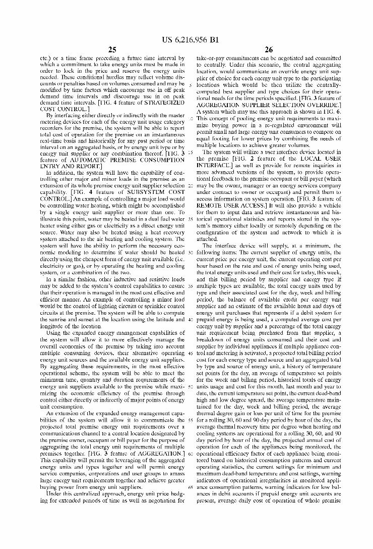
FIG. 1 is a block diagram shoWing the basic hardWare components of the system of the invention. As shoWn, the

US 6,216,956 B1 7
system includes at least one input device 10, a memory 20, a processor 30, a user interface and device control block 40 and an external device 50. Input device 10, Which may receive an input from a keyboard, mouse, microphone, telephone, external sensor or other, may receive user provided or non-user-provided input. As Will be described in greater detail beloW, user input may include temperature and other environmental condition comfort ranges as Well as timing and pricing preferences. Non-user input may include sensed environmental conditions such as temperature and humidity as Well as energy supplier cost information.
The input received by input device 10 is provided to memory 20 Where it is temporarily stored. Memory 20 may include any type of electronic or computer-related data memory such as Dynamic Random Access Memory (DRAM).
The data stored in memory 20 is accessed and processed by processor 30, Which may include a microprocessor, personal computer, or other type of processor capable of data manipulation and signal processing functions such as arith metic calculations. Numerous different environmental con dition control, price and energy consumption control and cost prediction functions may be provided by the system of the invention, as described beloW, Which functions require processing on the part of the processor. The functions may be selected by a user and the processing is carried out by processor 30 implementing softWare routines. One such function includes controlling the temperature Within a pre mises to remain Within user-inputted maximum and mini mum temperature comfort points and/or energy cost cutoff points.
The memory and processor may constitute a general purpose computer, such as a personal computer. The input, memory and processor all may connect to a common bus (not shoWn) on Which data is communicated betWeen the elements (from input to processor, processor to/from memory, etc.).
Processor provides output signals, in the form of digital, analog, mixed signal, or other, to user interface and external device control block 40. User interface and external device control block 40 may include separate devices, including, for examples, a display device, Which displays information to a user, and a control device, Which controls an external environmental condition control device 50 by providing a control signal or signals to such external device 50. One or more energy-consuming external devices 50
(loads) are controlled to maintain desired levels of environ mental conditions While minimiZing energy consumption. External devices 50 may include, for examples, heating systems, cooling (i.e., air-conditioning) systems and/or other environmental condition controlling external devices, such as heating, ventilation and air conditioning [HVAC] sys tems.
Not shoWn in FIG. 1 is a communications channel through Which the processor communicates With energy supply companies to receive future energy unit price schedules. As described beloW, based at least on user input parameters and price information, the processor Will select an energy sup plier to minimiZe energy consumption cost.
In one embodiment of the invention, as Will be described in detail beloW, a user Will input a desired temperature range for at least one energy unit price point and the processor Will compute a deadband temperature range for all possible energy unit price points (received from energy supply companies). The processor then Will control a heating and cooling system to maintain an indoor temperature Within the deadband range for each then-current energy unit price point.
10
15
25
35
45
55
65
8 Different embodiments of the invention, shoWn in FIGS.
2—4, range from simple to elaborate, in terms of the number of features and functions offered. Each of FIGS. 2—4 is a part functional, part structural block diagram illustrating the functions performed by, and the input and output elements of, the system. Each of the embodiments of FIGS. 2—4 includes at least the basic general hardWare elements shoWn in FIG. 1, With speci?c, exemplary input and output devices shoWn in each of FIGS. 2—4 for use With each system. For ease in understanding, the numbering of the functional blocks in FIGS. 2—4 remains consistent With the numbering in FIG. 1 of the corresponding hardWare elements for performing those functions. Input-providing devices 5—9 are shoWn in FIGS. 2—4. While input receiving device 10 is shoWn in FIG. 1, input functions 11—15 are shoWn in FIGS. 2—4. While memory 20 is shoWn in FIG. 1, data collection and storage functions 21 and 22 are shoWn in FIGS. 2—4. While processor 30 is shoWn in FIG. 1, processing functions 31—37 are shoWn in FIGS. 2—4. While user interface and external device control block 40 is shoWn in FIG. 1, output functions 41—45 are shoWn in FIGS. 2—4. Controlled output devices 51—58 are shoWn.
The speci?c input hardWare devices and output hardWare devices shoWn in FIGS. 2—4 are exemplary and are not intended as limiting. Any input devices that provide the required inputs and output devices Which may be controlled to provide the noted functions may be used With the system of the invention.
Each of input functions 11—15, storage functions 21, 22, processing functions 31—37 and output functions 41—45 is described separately beloW. Each embodiment of the invention, shoWn in FIGS. 2—4, includes different combina tions of such functions, ranging from the simplest (With the least functions)—shoWn in FIG. 2, to the most comprehen sive (With all functions)—shoWn in FIG. 4.
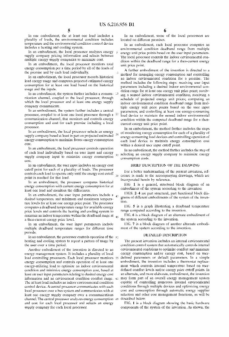
FIG. 6 is a block diagram of an alternate embodiment of the invention including a central processor 100 and multiple local processors 200A—200N. The central processor 100 communicates With each local processor 200A—200N over a multidirectional bus 300A—300N, respectively. Central pro cessor 100 also communicates via communications channel 400 With energy supply companies.
Each local processor 200A—200N operates as described With respect to FIGS. 1—4 for monitoring and controlling indoor environmental conditions and load devices for maxi miZing comfort and minimiZing energy consumption costs. Each local processor may be located on a different premise.
Central processor 100 monitors energy consumption and cost at each premise by receiving data from each local processor. Central processor 100 receives pricing informa tion from energy supply companies and may select an energy supply company for each local processor as an aggregate cost saving measure.
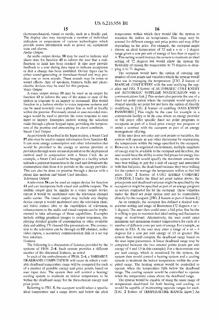
FIG. 7 is a block diagram of an alternate embodiment of the invention including multiple local processors 200A—200N. A main processor 200A communicates via communications channel 400 With energy supply compa nies. Each local processor 200A—200N communicates via a local communications channel 250 With each other local processor, including main local processor 200A.
Each local processor 200A—200N operates as described With respect to FIGS. 1—4 for monitoring and controlling indoor environmental conditions and load devices for maxi miZing comfort and minimiZing energy consumption costs. Each local processor may be located on a different premise or in a different location on the same premise.

US 6,216,956 B1 9
Main local processor 200A monitors energy consumption and costs for its oWn premise and in aggregate for each premise, as monitored by the other local processors 200B—200N, by received data from each other local proces sor 200B—200N. Main processor 200A receives pricing information from energy supply companies and may select an energy supply company for each local processor as an aggregate cost saving measure. Input Functions
Input functions condition and convert input device infor mation to data useable by the system. Each input function Will provide all the necessary support for each input device to provide data reliably and accurately. HardWare may include analog signal conditioning circuitry for a sensor, scanning logic for a keypad or a protocol stack for managing a communications link. Input Function 11
Input function 11 provides energy consumption and time and date information to function 21. The data may be obtained from any of a number of sources by methods such as by scanning keys of a keypad 7 for closures, decoding Dial Tone Modulation Frequency [DTMF] from a phone input, reading an energy meter 5 or submeter though count ing pulses or communicating over a communications link 6. Multiple input devices can be supported. The collected data Will be normaliZed in pulse count to units of energy con sumed. It is then passed to function 21 for short term storage and data considered of historical importance can be stored in function 22 for long term storage. Time and date may be available from certain meters and if available Would be collected and provided to function 21 Which in turn Would provide it to function 33. Input Function 12
Input function 12 provides energy cost information. Data can be collected from: a keypad through scanning keys for closures, decoding DTMF from a phone input, reading a Smart Card’s 9 rate tables or communicating over a com munications link either directly With one or more energy providers or With an energy cost service provider. The data Will be collected and provided in a standard digital or analog format to function 21 for short term storage. Each energy provider Will have its rate tables identi?ed and can have other factors included such as the length of time the tables are valid, discounts for the length of time the service is continuously used and penalties for excessive energy usage during certain time periods. The rate tables themselves may embody any type of pricing structures such as ?at rate, time of day, price tiers, etc. Input Function 13
Input function 13 provides Weather information. This information can be provided by keypad input, decoding DTMF from a phone input or through a communications link. The data can come from either an energy provider or a Weather service provider. The data can be in the form of discrete parameters representing temperature, humidity, Wind speed and direction or a Weather indeX value suitable for use in calculating the effect of Weather on cooling or heating a premise. The data may be provided at regular intervals and be suf?ciently localiZed for acceptable accu racy. The information Will be placed in a standard digital or analog format and passed to function 21. Data considered of historical importance can be stored in function 22 for long term storage. Input Function 14
Input function 14 interfaces With the user to alloW for data input and inquiries. Data can be entered by any standard data input device such as keypad input, decoding DTMF from a
10
15
25
35
45
55
65
10 phone input, analyZing voice input from a telephone or microphone, a handheld remote control device or a commu nication link When the user is not local to the system. The data can include temperature set points, comfort levels, cost goals or strategies, operational commands and inquiries about costs, operation or status. In one embodiment, the data includes a maXimum temperature level and a minimum temperature level for each of a number of energy unit cost points. The data also may include a maXimum cost level for each of a number of energy-consuming loads above Which cost level the user desires the load be turned off. This input is passed to function 21 for permanent storage. Input Function 15
Input function 15 provides for interfacing With sensors and equipment as Well any other data sources that may be appropriate such as a Smart Card 9 or communication link 6. Sensor types supported Will sense internal and eXternal environmental conditions including temperature and humidity, as Well as other conditions such as occupancy. These sensors can provide either raW signal levels Which Will be converted to a standard readable data format or themselves provide data output Which may be formatted and stored for use. Equipment that can effect the environmental conditions of the premise also Will provide input to this function. Types of equipment can include humidi?ers, dehumidi?ers, air ?lters, dampers and air ioniZation devices. The data they Will provide can include status, state, alarm and level. Function 15 Will pass all collected data to function 21 for storage and use by other functions. Storage Functions
Storage functions provide short term, long term and permanent storage of information provided by Input and Process functions. Short term storage encompasses data stored for one calculation or from one hour to 90 days. Long term storage can be from one to tWo years or longer. Permanent storage is data that once stored is never discarded or changed eXcept by the user. In terms of relative siZe, short term storage may store kilobytes, long term storage may store megabytes and permanent storage may store hundreds of bytes. Data Will be Written by input functions and Written and read by process functions. Storage Function 21
Storage function 21 collects all data and provides short term and permanent storage. All implemented input func tions collect data from input devices, format the data and pass the data to function 21 for storage. All active process functions retrieve data from storage, then process and store results in function 21. A process can decide to delete or modify any stored data not shared among multiple processes and can determine What data has historical value and Will be used in the future and tag it for long term storage. Function 21 Would move such data to long term storage if available and retrieve that data When requested by a process. Data shared among multiple processes that Was not overWritten by neW input data Would be tagged by each process as deleteable When no longer useful and be deleted When all sharing processes had tagged it so. EXamples of data types include user preferences and limits, Which may be perma nent data, energy rate tables and sensor inputs, Which may be short term data, and consumption pro?les and Weather data, Which may be short term data. Short term data having historical value may become long term data. Storage Function 22
Storage function 22 stores all long term data. It receives data from function 21 and stores it for a year or more, in one embodiment. This function may be local to function 21 or remote from it and the connection betWeen the tWo functions

US 6,216,956 B1 11
can be a hardware connection or a communications data link. It is possible that this function be implemented in a personal computer or as an added memory storage unit or as a separate service provider computer system. Processing Functions
Process functions use collected and stored data to make decisions and provide results. The functions are carried out by operating softWare on a processor (such as that of a general purpose computer). The results may be provided as output to the user or other processes Within the system or through output functions to output devices, service providers or external equipment. Connections betWeen processes and storage or output functions can be Within the same micro processor or physically separated by great distances and connected through a communications data link. As such, a process can be performed by a remote computer system or by a service provider and sent back to the local system to output functions. Process Function 31
Process function 31 provides a load estimation process, predicting future energy loading for other processes and for energy providers Which Will need to obtain customer provided information to manage future load requirements. Function 31 Will track usage by reading function 11 meter input data, if available, and track the effect of Weather by reading function 13 Weather input data, if available. Based on available data, function 31 Will provide a load estimate for the subsequent day, Week or month. Historic data Will be used if available in long term storage. If no data is available, then this function Will be dormant. Load estimates Will be stored in function 21 and provided to the selected energy provider once chosen and also used in the form of load pro?le and energy consumption data to make that selection in process 32. Process Function 32
Process function 32 selects an energy type, energy pro vider and pricing format, assuming multiple are available. The user may have available, more than one energy supplier, more than one type of energy, and may have local private energy generation or ‘cogen’ capability. Decisions then can be made regarding energy type, energy supplier and if and When cogen is to be utiliZed to realiZe cost savings. Deci sions Will be made With user-speci?ed criteria and possibly based also on predicted future uses, historical usage patterns, Weather patterns or forecasts, etc. Function 32 Would read cost and user input data collected by input functions 12 and 14, and load and time data from process function 31 and 33 to make those decisions. Absent user-speci?ed criteria to the contrary, the selections Will be made to minimiZe cost. If there is no function 12 data, then the entire process Will be dormant. Similarly, if there is no cogen capability or mul tiple energy types as indicated by function 14, then those portions of the process Will be dormant. Similarly, if there is cost data for only one supplier, then the selection process Will default to that supplier. If user criteria data is not provided, then a default set Will be used until such time as that data is provided. If there is no load information from function 31, then selection Will be made on the loWest rate for each hourly interval. Results of this process Will be provided to output functions 41 for cogen control, if available, and to function 42 for energy provider noti?cation of selection. This noti?cation may be by a Smart Card or through a communications link, as de?ned by function 42.
The costing process uses inputs read in function 21, the consumption data from function 11 and the selected energy supplier’s rate table data from function 12 to determine cost for storage in function 21 and to provide energy consump
15
25
35
45
55
65
12 tion data to the energy supplier, provided no automatic meter reading system or service is available to the supplier. Con sumption data Will be available from function 42. Process Function 33
Process function 33 provides time, date and day of the Week data. This process can be synchroniZed to the energy supplier’s reference if input function 11 can collect this data from the energy meter. It Will otherWise be set by the user. This process Will provide local time, date and day of the Week data and store it in function 21 for any process to use and is directly provided to the output function 43 for immediate display, if available. Process Function 34
Process function 34 provides a user-reporting process in response to user inquiry. The process collects data from function 21 and passes a response to function 43 to present to the user based on an inquiry input from function 14. Aset of de?ned inquiries Will be made available to the customer. A selection can be inputted by the user. Function 34 Will collect and format data for presentation based on that selection. Examples Would include: present temperature, temperature set point, present supplier, present cost this hour, cost to date this month, present consumption pro?le and present user selection criteria. These responses are subject to availability of the data Within function 21. Process Function 35
Process function 35 provides a system monitoring and alarm process. All other functions Will report their statuses to this function. If any function detects a problem or malfunction, then it Will be reported to function 35 Which Will store the status in function 21 and report the problem directly to function 43 for user noti?cation. Examples include reporting data no longer available for previously operating process, out of memory and temperature not responding to control. Additional interaction betWeen output functions and input functions Where feedback is expected Will be monitored and used to determine if proper operation of external equipment is occurring. This information also Will be stored and reported as required. Over time, this ability to monitor, measure and store the operational level of external equipment Will alloW for predictive reporting by function 15 as to the need for maintenance to restore the ef?ciency of that equipment. Process Function 36
Process function 36 provides at least the basic thermo static control and, With enhancements, can be used option ally to improve user comfort While reducing cost. On a continuous basis, function 36 reads function 21 for sensor and equipment inputs from function 15, user data from function 14, rate tables from function 12, based on the energy supplier selection performed by function 32, and time and date data from function 33, as available. Based on the data, a set point temperature variance is determined to provide the proper control to meet user requirements. Optional features implemented in function 36 include ramping, preheating and precooling, as described beloW. These options further vary the set point to improve user comfort While controlling cost. Adirect output is provided to function 43 to provide the user immediate access to tem perature data. As described beloW, a user may enter a minimum and maximum desired temperature range for at least one energy unit cost point. The function then Will compute a comfort deadband range for all possible energy unit cost points. The system then Will monitor the tempera ture and the energy unit cost and Will maintain an indoor temperature Within the computed range. As described beloW, the range may be greater as the cost of energy increases, thus

US 6,216,956 B1 13
automatically providing the user With cost savings by alter ing the indoor temperature range. Process Function 37
Process function 37 provides for control of other envi ronmental equipment to further improve user comfort and control cost. Function 37 reads cost information data from function 12, Weather data from function 13, user data from function 14 and equipment data from function 15, etc. Depending on the type of equipment and control provided over that equipment, function 37 can provide cost savings by operating the equipment during loWer energy cost periods, as opposed to set times of day, as may be necessary With air ?lters and ioniZation devices. Humidi?ers and dehumidi?ers can be controlled to enhance cooling or heating cycles Where a cost savings can be calculated. The devices are monitored for energy consumption and each may have different usage requirements (i.e., time of day, Weather-dependent, etc.) as speci?ed by the user. The state of the control of the equip ment is available directly to function 43 for immediate display. Output Functions
Output functions control and provide data to output devices, communication links and environmental equip ment. Output functions, for example, control external devices to maintain an environmental condition Within a comfort range While minimiZing energy consumption by the external devices. Each output function Will provide all the necessary hardWare and functional support each output device and controlled external device requires to function properly and reliably. Such support may include, for examples, contact closures, certain signal levels, audio capabilities, data display capabilities and the ability to format information and data over communications links controlled through a protocol stack for managing the data How and integrity. Output Function 41
Output function 41 provides the control to initiate local energy generation or cogen. Function 32 Will make the determination that cogen is the energy of choice to function 41 Which Will then use contact closures or a communication link 52 to initiate the process. Function 32 also Will deter mine the end of the cogen process and signal function 41 to turn off cogen. The system Will not provide for the direct control of the energy generation process but control only the on and off states. Output Function 42
Output function 42 provides noti?cation to the selected energy supplier of its selection and can provide consumption data if necessary. It can also notify those energy suppliers With Which the user has a relationship that they have not been selected for a speci?c time interval. Function 42 Will support a communication link and messaging to the energy suppliers. It also Will support storing this data in a Smart Card 57 for non-real time reporting. Consumption data, When there is no automatic meter reading system or service, can be provided to the energy supplier through the same means as the selection process. Output Function 43
Output function 43 provides data and display formatting support for the user output interface. This function can be implemented With a variety of output devices including: Liquid Crystal Display [LCD], Light Emitting Diode [LED], Vacuum Florescent [VF], Field Emissive Display [FED] or Cathode Ray Tube [CRT] displays 53; a voice response subsystem using a phone or speaker 55; a tactile output device like an electromechanical Braille pad; a television channel 56 added through a cable, satellite or other type of
10
15
25
35
45
55
65
14 set top box and a variety of communication links. The user output interface may be provided With data directly from process functions 33 through 37 for immediate access With out an inquiry. All other data is accessible through an inquiry processed by function 34. Additional indicators or enuncia tors may be implemented for providing statuses of certain functions such as poWer on, equipment state and alarm. Output Function 44
Output function 44 provides control for heating and cooling equipment. Function 36 Will determine the need for heating or cooling and signal function 44 to initiate the process. Contact closures, similar to standard thermostats, may be used to control the heating or cooling of the premise. A communications link 52 also may be available to com municate to equipment remote to the system. Output Function 45
Output function 45 provides control of environmental equipment other than that controlled by function 44. This equipment may include humidi?ers, dehumidi?ers, air ?lters, dampers and ioniZation devices. Function 37 Will determine the need to turn on or off a speci?c equipment type and signal function 45 to initiate the process. Contact closures 51 Will be used to control these units. A commu nications link also Will be available to communicate to equipment remote to the system. Output Devices
Output devices 50 are those devices that accept input from the output functions of the system. These devices Will interface With the appropriate output functions Which Will provide the proper control to those devices in response to the requirements of the system. Not shoWn are the speci?c external devices, including energy-consuming load devices, controlled by the system of the invention. The load devices may include environmental condition controlling devices such as heating or cooling systems, humidi?ers, or the like, or any energy-consuming device to be monitored and con trolled by the system of the invention. The controlled load devices Will receive control inputs through poWer modules, directly from the processor, from any of the output devices, or other.
Contact Outputs Dry contact closures 51 Will be used to provide control to
devices outside the system from functions 41, 42, 44 and 45. These contacts Will be rated for controlling relays and loW voltage circuits. The contacts may, for example, control the external load devices for energy consumption management and environmental condition control. Communications Link Output
This link 52 is similar to that described in the Input section except that the direction of the information Would be out from the system. The described links, regardless of the physical communications channel media, can be full duplex, half duplex or simplex, as dictated by the nature of the link and the needs of the input functions and output functions 41 through 45. Examples include: Satellite Which is simplex and normally only supports input functions, Ethernet Which is half duplex but Will support both input and output functions, and phone lines Which are full duplex and alWays supports both functions. Display Outputs
Adisplay 53 device capable of providing readable data of various forms and types to function 43 may be employed. The display can be textual or graphics based and have suf?cient display area to convey the required information. The construction can be custom or standard and be of any technology appropriate for the speci?c implementation such as LCD, LED, VF, FED, plasma, CRT and may be
US 6,216,956 B1 15
electromechanical, visual or tactile, such as a Braille pad. The display also may incorporate a number of individual indicators or enunciators of various technologies Which provide status information such as poWer on, equipment state and alarms. Audio Output An audio output device 58 may be used to indicate and
alarm state for function 43 to inform the user that a mal function or limit has been reached. It also may provide feedback to a user during data input to indicate acceptance or that a change has been instituted. Device types can be either sound-generating or transducer-based and may pro duce one or more sounds. These sounds may be tones or sound effects. Any of speakers, buZZers, bells and pieZo electric devices may be used for this purpose. Voice Output A voice output device 55 may be used as an output for
function 43 to inform the user of the status or state of the system in response to an inquiry or command. This Would function in a fashion similar to voice response systems and can be used remotely over a phone line as Well as locally Within the premise. Previously stored or user-recorded mes sages Would be used to provide the voice response to user input or inquiry. Examples include stating the selection made through a phone keypad input, providing the tempera ture of the premise and announcing an alarm condition. Smart Card Output As previously described in the Input section, a Smart Card
57 also may be used to output information from function 42. It can store energy consumption and other information that Would be provided to the energy or service provider or providers through some means dependent on the deployment method used in conjunction With a Smart Card. As an example, a Smart Card could be brought to a facility Which uploads a payment transaction to the card and doWnloads the consumption data from it to provide to the energy provider. This can also be done on premise through a device With a phone line modem and Smart Card interface. Television Output
Atelevision 56 can be used an output device for function 43 and can incorporate both visual and audible outputs. The audible output may be similar to a voice output device except it Would be modulated onto the television channel audio carrier. The visual output may include any display device except it Would modulated onto the television chan nel video carrier. Due to the capabilities of television, enhancements to the audio and visual outputs can be imple mented to take advantage of those capabilities. Examples include adding graphical images to output responses, dis playing detailed graphs of consumption or other available data and adding TV channel-like presentations. The connec tion to the television can be through an RF channel, audio/ video inputs, a secondary communication link or a set top box interface. Features
The folloWing is a discussion of features provided by the systems of FIGS. 2—4. Each system provides a different number of the discussed features, as noted.
In each of the embodiments of FIGS. 2—4, a VARIABLE DEADBAND COMPUTATION Will occur in Which a vari able deadband temperature range Will be computed for each of a number of possible energy unit price points, based on user input data. The system then Will control a heating/ cooling system to maintain an indoor temperature to be Within the deadband range for the then-current energy unit price point.
Referring to FIG. 5, the occupant Would select a speci?c ideal temperature and a range above and beloW the ideal
15
25
35
45
55
65
16 temperature Within Which they Would like the system to maintain the indoor air temperature. This range may be entered for different energy unit price points and may differ depending on the price. For example, the occupant might choose an ideal temperature of 72 and a + or — 1 degree
range given a cost per unit of energy of less than or equal to 4. This setting Would instruct the system to maintain an ideal setting of 72 degrees but Would alloW the system the ?exibility of raising the temperature to 73 degrees or drop ping it to 71 degrees.
The occupant Would have the option of entering any number of cost points and variables Which the system Would then use in managing the temperature. [FIG. 2 feature of MANUAL COST ENTRY With the user notifying the sup plier and FIG. 3 feature of AUTOMATIC COST ENTRY and AUTOMATIC SUPPLIER NOTIFICATION With a communications link.] This system also permits the use of a ?xed set point option Where the occupant Would specify a desired speci?c set point but not have the option of directly modifying it. [FIG. 2 feature of enabling DATA ENTRY PASSWORD] This might be the case for example in a commercial facility or in the case Where an energy provider or bill payer offer speci?c ?xed set point programs to occupants as part of a ?xed price energy use program or under a contract With the occupant as part of an energy management offering.
If the user does not enter any cost points or variables, the system Will operate as any other thermostat by maintaining the temperature Within the range speci?ed by the occupant. HoWever, in a re-regulated environment, multiple suppliers of energy may be available to the occupant and therefore, the user Would have the ability to enter bid prices for energy into the system Which Would specify the maximum amount the user Was Willing to pay for a unit of energy and associated With that bid price, the dead-band variance they Were Willing for the system to manage the temperature Within at that bid price. [FIG. 2 feature of COST BASED COMFORT CONTROL.] Under the ?xed set point option above, the price points and deadband variance might be speci?ed by the occupant or might be speci?ed as part of an energy program or service contracted for by the occupant. These variables under the ?xed set point option may not be controllable directly by the occupant. [FIG. 2 feature as part of feature 2.] As an example, the occupant has de?ned a desired tem
perature setting and range of ?uctuation (72 degrees + or — 1 degree). The user then could enter a bid price that he/she is Willing to pay to maintain that ideal setting and ?uctuation range or dead-band. Alternatively, the user could enter minimum and maximum desired temperatures for each of a number of different costs per unit of energy. For example, as shoWn in FIG. 5, the user may enter a range of + or — 4
degrees for a cost per unit energy of 13 or greater. The system then Would compute the deadband range based on the user input parameters. A linear deadband range may be computed betWeen the tWo entered points (costs per unit energy of 4 and 13 in this example). For a then-current cost per unit energy, Which is monitored by the system, the system then Would control a heating system and a cooling system to maintain the indoor temperature Within the com puted range. The heating system Would be controlled to operate When the temperature falls beloW the deadband range. The cooling system Would be controlled to operate When the temperature raises above the deadband range.
The system Would be capable of using the same range of temperature dead-band for both heating and cooling, or Would be capable of maintaining separate ranges for each. [FIG. 2 feature of TEMPERATURE RANGE input.] An

US 6,216,956 B1 17
example might be that a person Who is more tolerant of cold than beat, might set the dead-band for heating at 8 degrees off of the set point for a given price of an energy unit, While specifying only a 4 degree dead-band for the same energy unit price point for cooling. An additional feature of the system Would provide for the entry of a maximum and minimum actual temperatures Within Which the system is to manage the indoor air environment above or beloW the set point of the thermostat. [FIG. 2 feature of TEMPERATURE HI/LOW input.] Under this option, the user might enter 78 degrees as the maximum and 64 degrees as the minimum comfort range they Would like maintained. The system Would then utiliZe the current set point of the thermostat in conjunction With the minimum and maximum price and temperature inputs to compute a dead-band variance oper ating Zone for the premise. This computation Would be performed every time the set point or minimum and maxi mum price or temperature parameters are entered or modi ?ed. In addition, under this ?xed minimum and maximum temperature option, the system Would accept a set point greater than the maximum or less than the minimum tem perature parameter in its memory and Would use it as an override to these minimum or maximum parameters. [FIG. 2 feature of TEMPERATURE SET POINT input.] This override Would negate the dead-band option for either the heating or cooling cycle depending on Which degree setting Was over ridden.
An additional feature of the system provides an option for supplying the system With the previously mentioned mini mum and maximum degree settings for comfort along With an indicator for pricing that simply indicates at the loWest possible price. This feature permits the system to operate Within the minimum and maximum degree settings Without a minimum or maximum price. Under this scenario, the system Would scan the available pricing for the upcoming day and use the loWest priced energy units per time period (i.e. per hour) to create a dead-band plot for the day using the cheapest price period as the set-point price and the most expensive price period as the greatest variance set-point price. [FIG. 2 feature of COST CONTROL LEARNING.] It then Would operate Within that dead-band range for the day or other de?ned period, or until neW pricing for the time periods covered Were received. If neW pricing points are received, then the process Will re-compute the dead-band plot for the day. Under this scenario, it is also possible to enter only a minimum or maximum price point into the system. Entering just the minimum Would de?ne at What price for energy units the system is to maintain the minimum dead-band variance and that plotting higher price periods Will de?ne the maximum for the day or other de?ned period. [FIG. 2 feature of COST CONTROL LEARNING.] Enter ing just the maximum Will permit the use of the system shut doWn option if energy unit prices exceed those speci?ed as the maximum. 2 feature of COST CONTROL LIMIT
SHUTDOWN.] The historical data stored in an enhanced version of the
system could be used to assist in making this decision, or could be used to automatically determine the optimum settings, since the system, after being installed for a period of time, Will have suf?cient history data in its memory to provide the average consumption analysis data such as energy units used and cost of the energy units as a function of time, temperature, occupant changes in the set point and Weather related factors for normaliZation. [FIG. 4 feature of HISTORICAL CONSUMPTION ANALYSIS] This energy usage signature of the premise environmental temperature air management system is used to manage the economics of
10
15
25
35
45
55
65
18 its ongoing and future predictive operational costs as Well as to track its operational characteristic from the standpoint of detecting abnormalities in energy consumption or run times based on its historical energy use and operational charac teristics signature. [FIG. 4 feature of HISTORICAL OPERATIONS ANALYSIS] Based on these historical averages, the also may enter a
maximum range and/or deadband that they are Willing to tolerate either in the form of an offset to the set point or an actual minimum or maximum degree setting and a maxi mum price cutoff that the system is to Work Within While managing both the economics and the environmental com fort conditions.
Associated With the maximum price and dead-band variance, the user Would have the option of specifying to the system hoW it should react to prices higher than the maxi mum price speci?ed. These choices Would be to maintain the indoor air temperature at the maximum dead-band setting, or to activate an alarm condition and shut doWn the system until the energy unit price drops Within the alloWable range, or the alloWable range is changed to accept a greater energy unit price. [FIG. 2 feature of COST CONTROL LIMIT HOLD.] These choices could be different for heating versus cooling, permitting the option, for example, of shutting doWn the system for cooling and initiating an alarm if the maximum price point is exceeded While continuing heating operations even When the maximum price point is exceeded. To illustrate hoW this Would Work, referring to FIG. 5, the user might enter a maximum cost per unit energy of 13 above Which the dead-band range is 4 degrees + or —. The system then Would compute internally the variable dead band as a function of energy unit cost. The system then Would then scan the available energy suppliers ask price table for the current price of energy and, based on the occupant-supplied data, Would select the loWest cost energy source and supplier in an effort to remain as close to the user-de?ned comfort set point and spread as possible.
In this example, if the occupant had chosen not to enter any other than the original set point of 72 degrees and range of + and — 1, then the system Would choose the loWest energy unit cost and supplier and operate the heating and cooling system to maintain the indoor air temperature at the 72 degrees + or —1 degree default. If a minimum price Was entered by the occupant and the loWest cost per energy unit Was satis?ed, from one or more of the available energy unit suppliers, the loWest cost energy supplier Would be selected, and the minimum dead-band variance Would be selected.
This system further contemplates that prices posted by different energy unit suppliers Will contain at least the 3 folloWing components: (1) an energy unit component, (2) a distribution delivery cost and (3) a transmission delivery cost imposed by the distribution and/or transmission infra structure oWner or operator to move the energy units from their place of origin to the premise. The system has the ability to access and display to the oWner, occupant or bill payer, the many different sub-components making up the total cost of energy units supplied to or available to the premise. [FIG. 4 feature of ITEMIZED COST REPORT.]
During the selection process for an energy unit supplier, the system may select the loWest cost energy unit provider based on the total cost the energy units delivered to the premise. If multiple suppliers or types of energy units are available for the same price point, then the system might select the supplier of choice based on user-speci?ed energy unit type and supplier preference settings. If preference settings are not entered, then the system might rotate the suppliers to achieve equal election parity by type and energy

US 6,216,956 B1 19
units purchased during the billing period. [FIG. 3 feature of COST CONTROL SUPPLIER PREFERENCE WEIGHTING.] At all times, the system Would be capable of displaying the set point and the heating and cooling dead band range currently in effect and the actual temperature. [FIG. 2 feature of TEMPERATURE STATUS REPORT.]
In an enhanced version of the system, using the available historical data and any additional available input feeds such as outside temperature, Wind speed and direction, Weather information or indexes as Well as UV intensity, the system Will project the estimated total cost of operation for the day based on the asking price for energy units from suppliers . [FIG. 4 feature of COST ESTIMATE DAILY REPORT.]
In addition, the system Would forWard-project the cost of operation for each forWard period (for example the next 2 hours) and pre-cool or pre-heat the premise Within the alloWable ranges speci?ed by the user to minimiZe cost of operation during upcoming periods When energy prices are higher. [FIG. 2 feature of COMFORT PRECONDITIONING.] This real-time economic modeling Would be performed by the system on an ongoing basis and the system Would react to changes in energy unit pricing, external input feeds and occupant supplied changes to the ideal temperature setting and dead-band parameters to achieve maximum comfort and cost efficiency Within the user de?ned parameters.
To offset the effects of a radical price change such as might be found in a “time of day” rate structure, the system has the ability to perform temperature ramping based on a user activated option. This option Will cause the system to gradually ramp the temperature up or doWn over a period of time (i.e. 1 degree/30 min or 1 degree/1 hour based on either operator supplier ?xed rates of change or system-computed optimal ef?ciency rates) in response to energy price changes. [FIG. 2 feature of COMFORT RAMPING and FIG. 4 feature of WEATHER MODIFIED COMFORT RAMPING.] The optimal ramping algorithm Would be computed and executed if user-speci?ed rates are not present, based on the premise heat gain or loss historical data modi?ed to re?ect current conditions. UtiliZing this ramping technique, not only reduces energy usage during higher price periods, but also permits a gradual temperature change to occur in reaction to the higher price. Ramping back to a narroWer dead-band as prices drop or if a gradual recovery option is selected, uses a reverse recovery ramp. During periods of radical price change, ramping Will avoid or reduce the possibility of engaging the heating or cooling systems second or third level heating and cooling cycles Which usually self-engage When a temperature differential of more than 3 or 4 degrees exists betWeen the set point and the actual temperature.
The second and third stage heating and cooling cycles mentioned are incorporated into most modern reverse cycle or heat pump systems, and utiliZe multiple speed compressor motors for second and above-stage heating and cooling and auxiliary resistive heat strips, or in the case of a dual fueled system, gas ?red burners to supplement heating demands. In most cases, the initiation of subsequent stages of heating or cooling cycles on such systems results in an energy con sumption rate of tWo times that of the ?rst stage. By maintaining the systems operation in the ?rst stage cycle, maximum energy consumption ef?ciency is achieved. If, hoWever, thermal recovery does not keep up With the com puted or speci?ed ramp, subsequent stages of heating or cooling Will automatically be initiated When needed and if so equipped. As a result, recovery ramping, When used in conjunction With multi-stage heating and air conditioning
15
25
35
45
55
65
20 systems, Will minimiZe excessive energy usage and a gradual return to a narroW dead-band range by avoiding second and third stage initiation.
To maximiZe energy ef?ciency While the premise is not occupied or is vacant, as might be the case for a vacation home or second residence, the system Would support a minimum requirements function Which Would permit the entry of a very Wide dead-band range Which Would be enabled by the premise oWner, occupant or bill payer When conditions Warrant. In the minimum requirement mode, the dead-band Would be set at the maximum range regardless of the price of energy units (i.e., 40 degrees for heating and 90 degrees for air conditioning). [FIG. 2 feature of TEMPERA TURE LIMITING.] These degree settings Would, in most cases, be entered by the party enabling the function. Depending on the climate at the location, only one of the parameters may be needed to protect the premise from freeZing or excessive heat buildup.
To support such a condition, the system may accept a minimum range of 000 and a maximum of 999, Which Will be recogniZed as an off condition for the cooling and heating systems, respectively. UtiliZing such a system alloWs the occupant or utility bill payer to de?ne comfort in terms of both environmental comfort and Willingness to pay parameters, and Would alloW the energy unit supplier to achieve load management and maximiZe the utiliZation of resources by adjusting the energy unit pricing to increase or decrease demand for their product. The system in its simplest form Would use occupant input
parameters and energy supplier asking prices for energy units to select the energy supplier offering the loWest pos sible price from the available energy suppliers for current and future time periods. [FIG. 2 feature of COST CON TROL LEARNING.] In the enhanced embodiment of the invention, the system Will make the selection of an energy supplier also based on energy usage history data. [FIG. 3 feature of HISTORICAL COST CONTROL LEARNING.] The energy unit usage rate of associated heating and cooling system devices attached to the system Will vary depending on their particular designs and capabilities. For example, a standard air conditioning system usually has a fairly con sistent usage rate. In comparison, more sophisticated heat pumps have multiple speed compressors, fans and the ability to direct air ?oWs using damper controls to more ef?ciently maintain indoor temperature. Mixed fuel source units may have different usage rates depending on the fuel source being used (i.e. gas heat versus heat strips in the second or third stage of heating in more sophisticated heating systems).
To manage and report the cost of operation statistics to the occupant or bill payer if that feature is desired, the system Will need to have the energy unit usage rate of operation for each of its controllable heating and cooling devices in each of its possible con?gurations. In addition, the system Will need access to actual run time data to compute the estimated level of consumption for each controllable device. [FIG. 4 feature of MULTI-SYSTEM CONSUMPTION AND COST CONTROL.] This energy unit consumption rate data at a minimum Will be entered directly into the system as an optional parameter by the occupant or bill payer or system installer at system installation [FIG. 2 feature of MANUAL CONSUMPTION ENTRY.] or could be supplied to the system directly by a sub-metering device or by another system such as the InterLaneTM Home Manager or PoWer Manager on an interactive real-time basis. [FIG. 4 feature of AUTOMATIC CONSUMPTION ENTRY.] If interfaced to another system such as the InterLaneTM Home Manager & PoWer Manager, the system Would have the ability to record

US 6,216,956 B1 21
into the memory of or share operational statistics and all other historical data With the other system over a commu nications channel, thus improving the overall reliability and ef?ciency of both systems.
The system Would use its historical usage data to project future energy demand and produce economic models to obtain the maximum bene?t for the occupant or utility bill payer and the utility. By utiliZing the energy unit consump tion signature for any monitored and sub-metered appliance, in conjunction With Weather related data, the economic model Will continuously calculate and predict the future operating expense of the premise and individual appliances using the historical energy consumption signatures and external factors. This predictive model Will be used at a minimum to estimate future energy unit needs, costs, and identify and alarm unusual or abnormal consumption pat terns. [FIG. 4 feature of WEATHER CORRELATED HIS TORICAL CONSUMPTION ANALYSIS]
In addition, this economic model Will be capable of supplying normaliZed input data into energy efficiency mod eling tools such as the DOE-2.1 energy ef?ciency model to compute the overall energy ef?ciency of the premise. The system also Will provide comparative reporting on the ef?ciency of each monitored and measured appliance either directly or indirectly.
With the addition of sensing devices or data supplied to it from another source, the system Would build and maintain the history of these additional data points for inclusion in its model and, as a result, Would be better able to project the most ef?cient forWard planning model based on the occupant-supplied parameters. For example, the system could obtain, using a communications medium, Weather information or indexes that it Would use to maximiZe its ef?ciency. [FIG. 4 feature of AUTOMATIC WEATHER DATA ENTRY.] Information like an approaching front, afternoon prediction of rain, a projected increase or decrease in Wind speed, or change in direction, cloud cover or humidity could all be received over the communication link as codes or indexes and used by the economic modeling tool to effectuate the optimal environment and energy unit cost consumption scheme. The addition of an occupancy sensor or an interface With an occupancy knowledgeable device, such as an intrusion alarm system via a communications channel, Would permit the system to generate greater sav ings by alloWing greater use of the dead-band during periods When the premise is vacant Without jeopardiZing the comfort of the occupant. [FIG. 3 feature of COST CONTROL OCCUPANCY SENSING.] Upon detection of occupancy by a motion sensing device
or communication from an occupancy knoWledgeable device or system, such as an intrusion alarm system, the system could re-compute the most economical and environ mentally comfortable model based on the occupant-inputted parameters and the energy unit suppliers’ ask prices and adjust the heating and cooling systems to narroW the dead band range to an occupied state. To provide even greater savings When the premise is in an unoccupied state, the system could accept additional price and variance dead-band parameters to be used in the unoccupied state that might provide even greater variances in the dead-band than When the premise Was in an occupied state. This feature is not the same as the minimum requirements function mentioned above. An enhancement to the systems base functions may
include the ability of the system to develop a human factors pro?le of the occupants assuming they are not in a ?xed set point environment by tracking and recording changes in the
10
15
20
25
30
35
40
45
50
55
60
65
22 set points. At a minimum, tWo types of arti?cial intelligence Will be incorporated. First, the system Will track patterns of set point change as they relate to times of day, days of the Week and, at a minimum, track changes in these patterns for exceptions such as holidays. This function Would enable the system to track set point patterns or routines. For example, on Monday through Friday the occupant changes the set point at about 7:30 AM to re?ect a set back set point and changes it back to the normal setting at about 6:00 PM. At about 10:45 PM everyday, the occupant changes the set point to a set back set point. These patterns might re?ect an occupant’s desire to have different set points established during periods When they are at Work or asleep. By activating a function in the system called “folloW my
lead”, the system Would track such changes in set points and, over a period of time, Would be capable of automatically performing such set point changes. The occupant Would enable this feature of learning and automatically executing the learned patterns. In addition, the occupant Would be capable of resetting the learned patterns or disabling the automatic execution of these pattern at Will. [FIG. 2 feature of TEMPERATURE SET POINT LEARNING] The second of a multitude of such arti?cial intelligence
features Would be the tracking of set point changes by the occupant in relationship to the outside Weather conditions. Whenever the system detects a change in the set point, it Would be capable of recording and tracking the Weather conditions outside and develop a correlation to these factors. [FIG. 4 feature of WEATHER CORRELATED SET POINT LEARNING.] An example might be that on day When it is cold and the humidity is loW, the occupant might increase the set point to maintain a level of desired comfort. The reverse condition might exist When the temperature and humidity are high and the occupant loWers the set point to maintain a desired comfort level. This ability to track external Weather factors and automatically adjust the inter nal environmental conditions to meet the occupant’s desired comfort factors Will operate and be controlled in a similar fashion to those described earlier in the ?rst example. By utiliZing these control and comfort patterns, the system Will be able to maintain the indoor air (and similarly other environmental conditions) to achieve the desired comfort conditions of the occupant While, through performing the energy unit management functions, minimiZing energy con sumption cost, to achieve a balance of comfort and energy consumption efficiency.
In its simplest form under current regulation, the system Would be able to select betWeen the current suppliers of energy for the premise. The total energy units consumed Would be reported on the metering devices for the energy types attached to the premise. These could be, as examples, an electric, steam, gas, fuel cell or photo-voltaic system meters. The total premise energy units consumed by type as a function of time Would be recorded at these metering points. When choices of suppliers are made available to the system, the system Will track and record in its memory (and have the ability to also store these values in other systems’ memories such as the InterLaneTM Home Manager and PoWer Manager systems) the supplier of choice by type elected for the premise and consumption as a function of time, supplier and price paid. This data then may be com municated via a communications channel to either the energy unit broker for the premise or directly to the suppliers of the energy units for purposes of billing. [FIG. 3 feature of COST TRACKING AND SUPPLIER NOTIFICATION] The system also Will be capable of managing debit
accounts, prepaid accounts and credit accounts for the