environmental code of practice for elimination of ... · elimination of fluorocarbon emissions from...
TRANSCRIPT
Environmental Code of Practice forElimination of Fluorocarbon Emissions fromRefrigeration and Air Conditioning Systems
National Office of Pollution PreventionEnvironmental Protection ServiceEnvironment Canada
Report EPS 1/RA/2March, 1996
CANADIAN CATALOGUING IN PUBLICATION DATA
Main entry under title :
Environmental code of pratice for elimination offluorocarbon emissions from refrigeration and airconditioning systems
(Report ; EPS 1/RA/2E)Issued also in French under title: Code de pratiquesenvironnementales pour la l’élimination des rejets dansl’atmosphère fluorocarbures provenant des systèmes deréfrigération et de conditionnement d’air.ISBN 0-660-16448-5Cat. no. En49-26/1-2E
1. Fluorocarbons — Environmental aspects — Canada.2. Refrigeration and refrigerating machinery — Environmental aspects — Canada.3. Air conditioning — Equipment and supplies — Environmental aspects — Canada.I. Canada. National Office of Pollution Prevention.II. Canada. Environment Canada.III. Series: Report (Canada. Environment Canada) ;EPS 1/RA/2E.
TD887.F67E58 1996 363.73’84 C96-980160-2
© Minister of Public Works and Government Services Canada 1996N° de catalogue En49-8/2-4E
ISBN 0-660-16430-2Synergy Print and Copy Inc.
iii
Readers’ Comments
Readers who wish to comment on the contents of this report maysend their comments to:
Chief, Chemical Industries DivisionNational Office of Pollution PreventionEnvironmental Protection ServiceEnvironment CanadaHull, QuébecK1A 0H3
Cette publication est aussi disponible en français. S’adresser à:
Publications de protection de l’environnementProtection de l‘EnvironnementEnvironnement CanadaHull (Québec)K1A 0H3
Review Notice
This report has been reviewed by the National Office of PollutionPrevention, Environment Canada and approved for publication. Mention of trade names or commercial products does notnecessarily constitute recommendation or endorsement for use.
iv
Abstract
This Code of Practice was originally published in 1991 to fulfil theresponsibilities of the Minister of Environment for the formulationof environmental codes of practice as required under Section 8 ofthe Canadian Environmental Protection Act. The main purpose ofthis Code was to provide guidelines for the reduction ofatmospheric emissions of chlorofluorocarbons (CFCs) used inrefrigeration and air conditioning applications.
The Code of Practice (Code) has been revised, updated, andexpanded to cover six trade sectors, and an addendum of pertinentinformation that can be applied to all trade sectors such asIndustrial/Commercial, Residential, Residential DomesticAppliances, Mobile Air Conditioning, Mobile Refrigeration, andHeavy-duty Mobile Air Conditioning. The Code can also now beused as a reference for the reduction of hydrofluorocarbons(HFCs) and hydrochlorofluorocarbons (HCFCs) emissions.
The revised Code reflects the development of new alternativerefrigerants, new technologies, revised practices and procedures,and additional regulatory requirements. It has therefore beenretitled “Code of Practice for Elimination of FluorocarbonEmissions from Refrigeration and Air Conditioning Systems”.
v
Résumé
Ce Code de pratiques a d’abord été publié pour que le ministre del’Environnement assume les responsabilités que lui imposel’article 8 de la Loi canadienne sur la protection del’environnement en ce qui concerne la formulation des codes depratiques environnementales. Le principal objectif de ce Codeétait de fournir des directives pour la réduction des rejets dansl’atmosphère de fluorocarbures utilisés pour la réfrigération et leconditionnement de l’air.
Ce Code de bonnes pratiques a été révisé, mis à jour et élargi, eton y a ajouté des annexes. Il s’applique maintenant à tous lessecteurs de la réfrigération et du conditionnement d’air que sontles systèmes commerciaux et industriels, les systèmes résidentiels,les appareils électroménagers, les conditionneurs d’air mobiles, laréfrigération mobile et les systèmes mobiles de climatisation d’airde grande puissance. Ce Code peut également servir d’outil deréférence pour la réduction des rejets dans l’atmosphère deshydrofluorocarbures et des hydrochlorofluorocarbures.
Le Code révisé tient compte de la mise au point de nouveauxfrigorigènes de remplacement, de nouvelles technologies, depratiques et de procédures révisées et d’exigences réglementairesadditionnelles. C’est pourquoi il est dorénavant intitulé «Code depratiques environnementales pour l’élimination des rejets dansl’atmosphère de fluorocarbure provenant des systèmes deréfrigération et de conditionnement d’air».
vi
Table of Contents
Abstract ...................................................................................... ivRésumé ........................................................................................vGlossary .......................................................................................xAcknowledgments ..................................................................... xv
Section 1Introduction ................................................................................1
Section 2Commercial/Industrial Systems..................................................32.1 Design and General Practices.............................................32.1.1 General Design Principle....................................................32.1.2 Building Owners, Operators, and Managers .......................32.1.3 Relief Devices....................................................................32.2 Compressors......................................................................32.2.1 Mechanical Seals ...............................................................42.2.2 Seal Lubrication.................................................................42.2.3 Vibration ...........................................................................42.3 Condensers and Evaporators..............................................42.3.1 Condenser and Evaporator Vibration .................................52.3.2 Excessive Water Velocity ..................................................52.3.3 Water Quality ....................................................................52.4 Piping Fittings and Practices ..............................................52.4.1 Piping and Fittings .............................................................52.4.2 Piping Practices .................................................................62.5 Air Purge and Pump-down Systems ...................................72.5.1 Air Purgers ........................................................................72.5.2 Pump-down Equipment .....................................................82.5.3 Oil Draining.......................................................................82.5.4 Leak Detection and Alarms................................................92.6 Manufacturing Operations, Refrigerant, and Equipment ....92.6.1 Product Stewardship..........................................................92.6.2 Refrigerant Manufacturers ...............................................102.6.3 Manufacturers of Equipment............................................112.6.4 Holding Charges..............................................................112.6.5 Cleanliness of Systems.....................................................112.6.6 Leak Testing....................................................................112.6.7 Access Valves..................................................................122.7 Installation and Servicing .................................................122.7.1 Installation of Equipment .................................................122.7.2 General Items ..................................................................132.7.3 Cleaning and Flushing......................................................142.7.4 Service Records...............................................................15
vii
2.8 Conversion of Systems to an Alternate Refrigerant ..........152.8.1 Alternate Refrigerant .......................................................152.8.2 Selection of Equipment....................................................152.8.3 Prevention of Emissions and Leaks by Preplanning...........152.8.4 Equipment Replacement ..................................................162.9 Recovery, Reuse, and Disposal of Refrigerants ................162.9.1 Venting............................................................................162.9.2 Performance Testing........................................................172.9.3 Installation and Servicing .................................................172.9.4 Recovered Refrigerant, Reuse, and Disposal ....................182.10 Handling and Storage of Refrigerants...............................182.11 Records ...........................................................................202.12 Disposal of Equipment.....................................................202.12.1 Decommissioning.............................................................202.12.2 Decommissioning of Smaller Equipment ..........................202.12.3 Receiver Condenser .........................................................212.12.4 Equipment Disposal .........................................................212.13 Environmental Awareness Training..................................212.13.1 Training of Individuals Handling CFCs, HCFCs and
HFCs ..............................................................................212.13.2 Environmental Awareness Card and Certification.............212.13.3 Standardized Training of (Apprentice) Service and
Repair Persons.................................................................22
Section 3Residential Systems and Domestic Appliances ........................233.1 Type of Systems ..............................................................233.2 Equipment and Systems Design .......................................233.2.1 Compressor .....................................................................233.2.2 Isolating Valves ...............................................................233.2.3 Condensers and Evaporators............................................233.3 Equipment Manufacturing................................................233.3.1 Elimination of Emissions in Manufacturing.......................243.3.2 Cleanliness of Systems.....................................................243.3.3 Labels..............................................................................243.4 Installation and Servicing .................................................243.4.1 General Servicing ...........................................................243.4.2 Bolt-on Access Valves.....................................................253.4.3 Leak Testing and Repair ..................................................253.4.4 Recovery, Reuse, Recycling, and Reclamation .................263.5 Refrigerant Cylinders .......................................................273.5.1 Approved Refrigerant Container ......................................273.5.2 Refrigerant/Oil Mixtures ..................................................27
3.5.3 Contaminated Refrigerant ................................................27
viii
3.5.4 Refrigerant Container Belonging to a Third Party.............273.5.5 Cross-contamination of Refrigerant..................................273.6 Conversion of Systems to Alternate Refrigerants..............273.6.1 Basics of Conversion .......................................................273.6.2 Recommended Procedure ................................................283.6.3 Surplus Used Refrigerant .................................................283.7 Handling of Used Refrigerant...........................................283.7.1 External Agencies............................................................283.7.2 Destruction Facilities .......................................................283.8 Disposal of Appliances Containing Refrigerants ...............29
Section 4Mobile Air Conditioners (Automobiles)...................................304.1 Design .............................................................................304.2 Manufacture ....................................................................304.2.1 Cleanliness.......................................................................304.2.2 Discharge Evacuation ......................................................304.2.3 Leak Testing....................................................................314.2.4 Fluorescent Dyes .............................................................314.3 Servicing .........................................................................314.3.1 Venting............................................................................314.3.2 Container Size .................................................................314.3.3 Equipment Conversion.....................................................314.4 Handling of Refrigerant in Automobiles Slated for
Wrecking.........................................................................324.5 Training of Personnel.......................................................334.6 Records ...........................................................................33
Section 5Mobile Refrigeration.................................................................345.1 Design .............................................................................345.1.1 Compressors....................................................................345.1.2 Condensers on Ships........................................................355.1.3 Pipelines and Connections................................................365.2 Servicing .........................................................................365.2.1 Planned Preventative Maintenance ...................................365.2.2 Regular Planned Preventative Inspections ........................365.3 Equipment Conversions ...................................................365.4 Operator Education .........................................................37
ix
Section 6Heavy-duty Mobile Air Conditioning Systems ........................386.1 Design .............................................................................386.2 Mobile Air Conditioning Design Features.........................396.2.1 Design Features ...............................................................396.2.2 Mobile Centrifugal Chillers ..............................................396.2.3 Excessive Water Velocity ................................................396.2.4 Condenser Water Treatment ............................................406.3 Pipelines and Connections................................................406.4 Planned Preventative Maintenance ...................................406.5 Systems Conversion to Alternate Refrigerants..................40
Section 7Strategic Planning .....................................................................417.1 Strategic Planning for Existing Facilities Containing
Chlorofluorocarbons........................................................417.2 Goal ................................................................................417.3 Refrigerant Inventory and Audit ......................................417.4 Conservation Objective....................................................427.5 Development of a Corporate Stewardship Policy.............427.6 Establishing Priorities ......................................................42
Appendix AList of Recognized Industry Standards ....................................43
Appendix BExamples of Labels...................................................................44
x
Glossary
ASHRAE - American Society of Heating, Refrigerating and AirConditioning Engineers.
Azeotrope - A product resulting from the combination of two orthree compounds that have identical vapour and liquidcompositions. An azeotrope cannot be separated into itssubstituent parts by distillation. Azeotropes will fractionateslightly and experience temperature glide outside of theidentified azeotropic points, (ASHRAE std. 34 definitions)(See Appendix A).
Blend - A refrigerant mixture of two or more chemical compoundsblended in a specific ratio which can be separated bydistillation. Regular blends may have up to 10° C or moretemperature glide.
Certified Person - A person who has successfully completed theEnvironment Canada Environmental Awareness Course forthe Environmentally Safe Handling of Refrigerants(previously for handling ODSs). This is not the same as atrade certified and qualified person, nor is it intended toimply any trade qualification. The certified person referredto herein will include those persons who are activelyinvolved in the Refrigeration and Air Conditioning Industry,e.g., Service Person, Repair Person, Installation Person,(Refrigerant) Stores Person, Domestic ApplianceTechnician, Refrigeration and Air Conditioning Mechanic,Automotive Mechanic, Heavy-duty VehicularMechanic/Technician, Industrial Mechanic, TechnicalRepresentatives, and Power Engineers. This course ismandatory in most provinces.
Chlorofluorocarbon (CFC) - A stable chemical containing onlychlorine, fluorine and carbon atoms. Chlorofluorocarbonsare ozone-depleting substances (ODSs).
Consumption - Consumption of a controlled substance for a givenperiod is the sum of the quantities produced and importedinto the country during the given period of time, less thequantity exported. For the purpose of determining acalculated level of consumption, it excludes any quantity ofcontrolled substance that, when imported or exported, wasalready used, recovered, recycled, or reclaimed.
xi
Container - A container which is intended to contain only ozone ornon-ozone-depleting substances such aschlorofluorocarbons (CFCs), hydrochlorofluorocarbons(HCFCs), hydrofluorocarbons (HFCs), or blends, whetherthe substance contained in the container is under pressure ornot. For example, a charging cylinder is a container used todecant small amounts of refrigerant (of various types) into asystem, but is not an approved storage or transportationcontainer. Containers may be cylinders or drums made outof metal or glass.
Approved Container - An approved container is a storage drum orcylinder that conforms to the Canadian TransportCommission specification (CTC) which permits its use forthe substance it contains. For imported products from theUnited States, Department of Transportation containerspecifications (U.S.) are also recognized for storage andtransportation.
Approved Cylinder - is a refillable/recyclable CTC approvedcontainer that is properly colour-coded for the substance itcontains as per the ASHRAE Standard, and it should alsobe properly labelled in accordance with this Code and CTCregulations.
Designated Ozone-depleting Substance - An ozone-depletingsubstance that is listed by name in the Montreal Protocol, orsubstances added to the list as subsequent amendments tothe Protocol.
Disposable Container - A container designed to be used only oncefor the transportation or storage of a virgin substance, suchas CFC, HCFC, HFC, blends, designed in accordance withCTC specification 39 (DOT 39 if made in the U.S.A.). Thiscontainer should not be used for recovery or recyclingpurposes, or for any other use and should be returned to thesupplier when empty. Refillable containers are preferred forreplacing existing disposable containers, as they areconstructed with better one-way valves and designed formultiple use. There is minimal chances for emissions to takeplace.
Global-warming Potential (GWP) - A global-warming potential isthe time-integrated change in "radiative forcing" due to theinstantaneous release of 1 kg of a trace gas expressedrelative to the radiative forcing from the release of 1 kg
xii
carbon dioxide (CO2).
Holding Charge - A charge of an inert or a refrigerant gas put intoa system or equipment to ensure that there is a positivepressure to prevent leakage of air or moisture into thesystem or the equipment.
Hydrochlorofluorocarbon (HCFC) - A chemical compoundcontaining only hydrogen, chlorine, fluorine, and carbon. Hydrochlorofluorocarbons are less damaging to the ozonelayer than chlorofluorocarbons. These compounds(HCFCs) are considered as an interim replacement forCFCs.
Hydrofluorocarbon (HFC) - A chemical compound containinghydrogen, fluorine, and carbon. With no chlorine orbromine, HFCs do not destroy the ozone layer but have aglobal- warming potential, as do ozone-depletingsubstances.
Mixture - A refrigerant that contains oil and contaminants includingother refrigerants. The term cocktail mixture describes theinadvertent mixing of two or more refrigerants, usually theyare not recyclable or reclaimable.
Near-azeotrope - Sometimes called a NARM, this chemical productis formed by combining two or more compounds. Itsvapour and liquid compositions are nearly identical. Near -azeotropes have a temperature glide of less than 2°C(ASHRAE 34 definitions) (see Appendix A).
Ozone-depletion Potential (ODP) - A measure of the relativecapability of a particular chemical to destroy ozone. TheODP is measured against CFC-11 which has an assignedODP of 1.0. Internationally accepted ODP values havebeen established by UNEP.
Ozone-depleting Substance (ODS) - A chemical compound that issufficiently stable to reach the stratosphere and is capable ofreacting with stratospheric ozone, leading to ozonedepletion.
Perfluorocarbon (PFC) - A chemical compound containing onlycarbon and fluorine.
Recovery - The collection and storage of refrigerant from any
xiii
system or equipment, containment vessels, etc., in approvedexternal recovery storage cylinders, or in drums for lowpressure refrigerants during servicing, repair, or beforeequipment disposal.
Reuse - The reuse of previously recovered refrigerant withoutprocessing.
Recycling - To improve the quality of recovered refrigerant beforere-use. This is to clean refrigerant by oil separation,distillation, and single or multiple passes throughreplaceable core filter-driers to remove moisture, acidity,and particulate matter. The cleaned refrigerant can then beused at a job site or service shop. Recycling may be doneon or off site.
Reclamation - The re-processing and upgrading of refrigerant byfiltering, drying, or distillation and chemical treatment of therecovered refrigerant. The re-processed substance willrequire laboratory analysis to verify that it meets a specificquality standard. This involves processing "off- site" at are-processing or a refrigerant manufacturing facility.
Refrigerant - A fluid that absorbs heat at a low temperature andpressure, with a change of state, and rejects heat at a highertemperature and pressure.
SAE - Society of Automotive Engineers.
Servicing - Includes installations, maintenance, testing and repair,alteration, conversion, mothballing and decommissioning.
Sweep Charge - Sweep charge is a procedure in which therefrigerant is circulated in a closed-loop system to clean theequipment. The refrigerant is subsequently recovered.
Threshold Limit Value (TLV) - is the measure of toxicity effect. Itis the limit of concentration of a substance in the air that anaverage person can tolerate without any adverse effect for aperiod of eight hours of continuous exposure. The TLVis assigned by the American Conference of GovernmentalIndustrial Hygienists (ACGIH).
Tonne of Refrigeration (tR) - is a unit for refrigeration capacityequal to 3.517 kW (12 000 Btu/h).
Ultraviolet Radiation B (UV-B) - This form of radiant energy is
xiv
emitted by the sun. It has a wavelength between 280 to 320nm. Exposure to excess UV-B is harmful to humans,animals, and plants. The ozone layer forms a protectiveshield that helps to protect the earth from excessive levels ofUV-B radiation.
UNEP - United Nations Environmental Program.
White Goods - Household domestic appliances such as freezers orrefrigerators, that include a 115/230 volt self-containedplug-in refrigeration or air conditioning system (or gas-operated system for mobile homes).
Zeotropes - Are refrigerant blends consisting of a combination oftwo or more different chemical compounds, often usedindividually as refrigerant for other applications. Unlikeazeotropes, zeotrophic blends separate more easily into theirsubstituent parts.
B 52-M1995 Mechanical Refrigeration Code - (asamended/updated from time to time) This is a code ofpractice to ensure that adequate safety standards areconsistently applied to refrigeration, air conditioning, andheat pump systems. It applies to the design, construction,installation, operation, and inspection of every type ofrefrigeration system. This Code is mandatory in allprovinces.
B 51 Code for Boilers, Pressure Vessel and Pressure Piping Code(as amended/updated from time to time) - This code ofpractice ensures adequate safety standards for all types ofinstallations involving high pressure systems [> 103 kPa(>15 psig) design pressure]. This Code is mandatory in allprovinces.
xv
Acknowledgments
The preparation of this document would not have been possiblewithout the cooperation and assistance from many individualsrepresenting the Refrigeration and Air Conditioning Industry,Industry Associations, Organized Labour, Federal, Provincial, andTerritorial Governments, Product Manufacturers, andEnvironmental Groups. Environment Canada greatlyacknowledges their contributions.
AIA - Automotive Industries Association of CanadaAIAMC - Association of International AutomobileManufacturers of CanadaBOMA - Building Owners and Managers AssociationCASE - Coalition of Automotive Safety and theEnvironmentCEASA - Canadian Electronic and Appliance ServiceAssociationCETAF - Corporation des entreprises de l'air et du froidCFIG - Canadian Federation of Independent GrocersCF of L - Canadian Federation of LabourCMMTQ - Corporation des Maîtres mécaniciens enTuyauterie de QuébecCTA - Canadian Trucking AssociationEC - Environment CanadaFoE - Friends of the EarthFPWG - Federal/Provincial Working Group (Ozone-depleting Substances)HRAI - Heating Refrigerating and Air ConditioningInstitute of CanadaMVMA - Motor Vehicle Manufacturers AssociationNDHQ - National Defence HeadquartersNRC - National Research Council of CanadaPWGSC - Public Works and Government Services CanadaRSES - Refrigeration Service Engineers Society
1
Section 1
Introduction
The use of refrigerants contained in a closed loop is both safe and efficient as long as escape tothe atmosphere is prevented. The emission of ozone-depleting substances (ODSs), such aschlorofluorocarbons (CFCs), halons, and hydrochlorofluorocarbons (HCFCs), to the atmospherewill continue to adversely affect stratospheric ozone concentrations for many years. Even if allemissions were eliminated, the increased UVB radiation reaching the earth’s surface caused byearlier emissions will affect humans, plants, and animals. In addition, ODSs have a global-warming effect. Hydrofluorocarbons (HFCs) contribute to global warming but have no ozone-depleting potential.
The strategy is to target the most damaging chemicals first to reduce and eventually eliminateozone-depleting substances (ODSs) from being emitted to the atmosphere. The CanadianEnvironmental Protection Act (CEPA) Ozone-depleting Substances Regulation was amended toeliminate the production and importation of CFCs as of January 1, 1996. Most provinces alsohave regulatory programs in place for the recovery/recycling/reclamation of refrigerants. Environmental awareness training of service persons in refrigeration and air conditioning fields, ismandatory in most provinces.
The Code has been revised to reflect our national and global commitment to pollution preventionas well as the objectives of the National Action Plan for the Environmental Control of Ozone-depleting Substances and their fluorocarbon alternatives. The Code
has been expanded to include hydrochlorofluorocarbons and hydrofluorocarbons. Although theCode does not address nonfluorocarbon refrigerants, which are used in specific applications, itshould be recognized that these may cause other environmental and/or safety concerns. Thefuture development of additional technologies and practices is not discussed in this report. However, technological developments which further improve the ability to eliminate all emissionsshould be adopted if shown to be feasible.
The Code will require revision as new technology and regulatory advancements are made toaddress future problem areas. It is a guideline that will be of interest to manufacturers,contractors, service persons, environmental monitors, and regulators. It can also be used as atemplate for further consistency and harmony of provincial regulations concerning refrigerantemissions into the atmosphere. The Code has been developed in consultation with active andcorresponding stakeholders from all trade sectors such as manufacturers, contractors, organizedlabour, trade associations, service industry representatives, environmental interest groups, federaland provincial representatives, and regulators.
The refrigerants such as HCFCs, HFCs, and blends thereof are fluorocarbons which have beenidentified as suitable replacement refrigerant alternatives. The HCFCs have a much lower ozone-depletion potential (ODP) than CFCs. Some HFCs have a higher global-warming potential thanHCFCs (although much less than CFCs) but have no ozone-depletion potential. No CFC

2
alternative is available today that is totally benign, and thus a proactive approach to pollutionprevention continues to be necessary. Recognizing that these alternatives will still have someimpact on the environment, the same methodologies used to eliminate emissions of CFCs shouldbe used to recover and recycle HCFCs and HFCs. Canada is committed to the goal of totalcontainment and elimination of the use of ozone-depleting substances, in harmony with otherdeveloped countries around the world.
3
Section 2
Commercial/Industrial Systems
2.1 Design and General Practices
This section deals with the design of refrigeration and air conditioning systems and theircomponents, and identifies possible sources of refrigerant emissions of CFC/ HCFC/HFCs to theatmosphere.
Application of established technology in both the design, construction, proper operation, andmaintenance of refrigeration systems constitutes a good foundation for the prevention ofrefrigerant leakage to the atmosphere. Improved design of systems and use of new technologiesand practices are essential for reduction and elimination of emissions.
2.1.1 General Design Principle
Commercial/Industrial refrigeration and air conditioning sectors are the major source ofemissions. Environmentally sound design, therefore, is an important goal in pollution prevention. Equipment manufacturers, distributors, and associated service industries should incorporateproduct stewardship into their corporate policies, if not already present.
2.1.2 Building Owners, Operators, and Managers
Equipment owners and managers using ODS equipment should be informed of the environmentalimpact of ODS emissions and use of alternative refrigerants. The immediate need is tocommunicate that planned preventative maintenance is an essential component of preventingemissions. The second need is to improve maintenance techniques and procedures for maintainingthe equipment to reduce or eliminate the potential for refrigerant release.
2.1.3 Relief Devices
Effective on the date of publication of this document, all new units containing over 10 kg (22lb) of refrigerant should have a self-reseating relief valve vented to the outside atmosphere inaccordance with the applicable B-52 code requirements. Also, units with over 50 kg (110 lb)should have a monitoring system in the compressor room, capable of detecting leakage greaterthan 30 ppm.
2.2 Compressors
To prevent fugitive emissions, compressors or associated equipment fitted to them, e.g., gaugeand cut-out connections, oil return, oil drain, oil level sight glass, relief valve and connecting pipework, need to be inspected regularly according to manufacturer's specifications, or at least twice ayear if no specifications exist.
4
2.2.1 Mechanical Seals
Damaged mechanical seals on open type compressors are a frequent source of refrigerant leakage.Some manufacturers indicate that a small amount of oil leakage is required to keep dirt out of theseal and keep the seal surface lubricated. However, damage to the seals may be caused by oilcontamination or lubrication breakdown.
A clean, dry system is essential for prolonged mechanical seal effectiveness to eliminate emissions. Compressor oils used for HCFCs and HFCs will absorb moisture readily and must be kept dry toprevent refrigerant decomposition.
Straining and filtration of refrigerant and compressor oil should be provided on new equipment tominimize mechanical seal wear and thereby reduce the possibility of having leaks. Existingequipment should be modified to include these features.
Gland housing should be designed to prevent oil draining away from the mechanical seal duringshutdown, which may cause leakage due to seal face damage on startup.
2.2.2 Seal Lubrication
During shutdown the mechanical seals on large open compressor systems should be lubricatedweekly before the compressor is started. A film of oil maintained on the shaft and seal surface,helps to prevent refrigerant from escaping.
2.2.3 Vibration
Compressors should be mounted on a solid foundation and/or with vibration eliminators toprevent leaks due to vibration and failures.
Gauges and Cutouts. Snubber valves should be used to protect gauges and cutouts. They arealso required to permit removal of these devices for repair.
Isolating Valves and Access Valves. All commercial and industrial compressors should haveisolating and access valves on both the suction and discharge sides. New units/systemsimmediately or from the date of publication of this document should have "refrigerant recoveryaccess valves" sized to allow 0.64 cm (1/4") of free area for flow of refrigerant on units/systemshaving up to 4 kg (8.8 lb) of refrigerant charge and 0.95 cm (3/8") I.D. for systems containingover 4 kg (8.8 lb) of refrigerant to permit recovery of refrigerant before the system is opened.
2.3 Condensers and Evaporators
Effective on the date of publication of this document, the refrigerant should not be used as aholding charge for storage or shipping; use dry nitrogen or dry air that meets ASHRAE standards.
2.3.1 Condenser and Evaporator Vibration
5
Excessive vibration from compressors or other equipment can cause evaporator and condensertube failure. Antivibration mountings and vibration eliminators should be used where feasible. Piping should have flexible connectors and be solidly anchored. Equipment should be inspectedperiodically to identify and remediate any excessive vibrations.
2.3.2 Excessive Water Velocity
Excessive water velocity through the tubes of shell and tube units should be avoided. On largerunits (e.g., greater than 50 tR), eddy current testing of tubes every three years and water flowmeasurements will help minimize refrigerant losses due to tube failure. Adequate protectionagainst water hammer is also recommended to reduce failure.
2.3.3 Water Quality
Water treatment and filtration should be used where needed to avoid corrosion or erosion failure. Careful selection of tube materials can also help to minimize corrosion.
For non-ferrous tubes, sacrificial anodes should be used to reduce corrosion pitting.
Reduced or suspended water flow can lead to serious corrosion problems. Flushing and a regularinspections should be done.Sacrificial anodes are ineffective unless there is water flowing through the tubes. Tube sheetsshould also have a tube sheet vent valve to avoid trapped gases. These should be purged at leastonce a month.
2.4 Piping Fittings and Practices
2.4.1 Piping and Fittings
Vibration eliminators should be included in the suction and discharge lines near the compressor toprevent and eliminate leaks and vibration transmission.
Adequate support of pipeline connections to the compressor should be provided to avoidunacceptable stresses that could lead to leakage.
All pipelines should be designed so that the number of joints is minimized. Swedged joints shouldbe used by both manufacturing process and the service person in the field. Welding or brazing isthe preferred method of attachment on all refrigerant lines. The use of back seating access valvesfor attaching control and safety devices or gauges is preferred. Capillary lines on these devicesmust be positioned to ensure they can absorb vibration without rubbing together or againstanother object.
Gasket Material Compatibility. Ensure that gaskets are compatible with therefrigerant/refrigerant oil mixture where flanged joints are used, especially when the system isconverted to an alternative refrigerant or oil. Equipment manufacturers should always beconsulted before any retrofitting to help avoid leakage.Welded or Brazed Flanges. To eliminate potential leaks in new systems, welding or brazingshould be used to join flanges to the pipeline, instead of threaded connections. Where threaded
6
connections must be used, fluoropolymer film is the preferred pipe lubricant. On existing systemsback-weld screwed flanges should be used where possible.
Back Seating Valves. Use valves designed for tightening or replacement of the glandpacking/diaphragm under line pressure except when ball valves are involved. Be sure to checkvalves carefully before servicing. Leak test the gland-packing nut regularly.
Capped Valves. Capped valves which can retain any leakage from the spindle gland should beused for all service stop valves. Regular operating valves in the system should be leak testedregularly.
Welded, Brazed Valves. Valves with welded, brazed, or flanged connections should be usedinstead of a flared or screwed type, for sizes greater than 19 mm (3/4") outside diameter (O.D.). For small sizes use compression fittings instead of flared fittings.
Bolt-on Valves. Bolt-on valves should not be used on smaller applications. Saddle valves can beused as a tool but must be replaced by weld-in access valves or welded shut before the serviceperson leaves the site. One exception is for recovery of refrigerant when a bolt-on valve can beused during decommissioning of smaller equipment.
Isolation and Access Valves. Valves allowing isolation of all vessels and equipment are requiredto minimize the risk of refrigerant loss during servicing. Access valves for recovery of residualrefrigerant in isolated components are also required. Any piping or segment between two shut-offvalves must be protected by a pressure-relief, in accordance with the B52-M1995 MechanicalRefrigeration Code (as amended from time to time).
Isolation valves should be added, if not present, when vessels or equipment have to be shut downand evacuated for service.
2.4.2 Piping Practices
Pipelines should always be supported against vibration stresses, which cause leaks, by beingadequately clamped to solid fixtures. Use insulated hangers for non-ferrous pipe. Vibrationeliminators and expansion bends should be used. Use trombone bends or sprung hangers for linestoo large for vibration eliminators. Gauges, high pressure and low pressure shut-off, and oilsafety switches should be connected to the main system via flexible connections so that vibrationsare absorbed.
Filter Driers. To prevent leakage, filter driers in the range of 5 to 20 µm should be used toreduce particulate matter and avoid damage to the mechanical seal faces and other working partsof compressors. Similar damage can also be caused to motor windings and compressor parts ofhermetic and semi-hermetic compressors. A moisture indicating sight glass is stronglyrecommended. New systems should have a liquid line filter drier of sufficient size welded intoplace at the time of manufacture, to protect the equipment. Replaceable filter drier cores areavailable for larger systems to avoid emissions.
The drier should have isolation and refrigerant recovery connections. A new filter/drier should be
7
installed, complete with required valves in the case of a system that is opened to replace acomponent that has no filter/drier.
Welding Blanket. Refrigerant should not be used as welding blanket. Dry nitrogen should beused during welding or brazing.
Relief Devices. A nonfragmenting rupture disc in conjunction with a self-reseating type reliefvalve is recommended for low pressure refrigerant systems. All relief devices must be vented tothe outdoors.
Three-way Refrigerant Valves. A three-way refrigerant valve is required to accommodate dual-relief valves on all high pressure refrigerant machines with a charge of over 50 kg (110 lb), tofacilitate repair or replacement. To eliminate emissions the relief valve setting shall be inaccordance with the B52-M1995 Mechanical Refrigeration Code. (As amended from time totime).
2.5 Air Purge and Pump-down Systems
2.5.1 Air Purgers
Air purge systems should vent outdoors. When purge systems operate, some refrigerant isemitted with air and frequent purging indicates a system leak. High-efficiency purgers will help tosignificantly reduce refrigerant purge emissions. In conjunction with adsorption technology, a100% capture rate of normal purge emissions is possible. To correct the problem, trainedqualified service persons must inspect and repair all leaks in the system. Regular leak testing isessential.
High-efficiency Purgers. Effective on the date of publication of this document, all new lowpressure centrifugal units using refrigerants such as CFC-11, CFC-113, or HCFC-123 should befitted with high-efficiency air purgers or other device that is designed to emit less than 0.1 parts ofrefrigerant per part of air during usual operation, according to manufacturer's specifications.
It is recommended that by January 1, 1999, existing chillers be retrofitted with a new high-efficiency purge or other device that is designed to reduce emissions below 0.1 kg ofrefrigerant/kg of air.
After January 1, 2000, all purge systems should have zero refrigerant emissions.
Pre-vacuum systems are available to prevent low pressure systems from going into a vacuumduring idle periods. Potential refrigerant loss or leakage will be reduced; however, leaks shouldstill be eliminated through proper leak testing and maintenance.Residual refrigerant should also be recovered from the purge exhaust port using the best availabletechnology. Systems to be shut down more than four months should have the refrigerantremoved and transferred to approved storage vessels or containers.
2.5.2 Pump-down Equipment
8
Effective on the date of publication of this document, all new high pressure refrigeration and airconditioning units with a refrigeration capacity of 35.2 kW (10 tR) or greater, should incorporatea fully protected and isolatable liquid receiver to facilitate pump down during servicing, repairs, orwinter lay ups. A condenser and receiver combination of sufficient capacity to hold the completerefrigerant charge is also acceptable.
Auxiliary Receivers. If manufactured before the date of publication of this document, unitscontaining a refrigerant charge of over 10 kg (22 lb) should be installed with auxiliary receivers, ifrequired, to hold the complete refrigerant charge during winter and summer. Units using capillaryexpansion control, however, need not necessarily be fitted with an isolatable liquid receiver. Forsmaller systems approved containers can be used.
Shell and Tube Condenser. The previous paragraph on auxiliary receivers does not necessarilyapply to systems containing a shell and tube condenser if the condenser shell is on the refrigerantside; is large enough to contain the entire refrigerant charge; is fully isolatable and is protected bya pressure-relief device.
Evaporator and Accumulator. The paragraph on auxiliary receivers does not necessarily applywhen the evaporator and/or liquid accumulator separator can contain the entire refrigerant chargeand is fully isolatable and protected by a pressure-relief device.
Pump-down Attachments. Large systems may incorporate a separate pump-down condensingunit and receiver. Compressors and major equipment should be fitted with suitable refrigerantaccess valves to allow connection of a recovery unit for the removal of refrigerant before serviceor repair operations or any section of the system.
2.5.3 Oil Draining
Since refrigerants are soluble or miscible in compressor lubricating oils, compressor crankcasesshould be designed for pumped-down to below atmospheric pressure, before the oil is removed. High pressure systems should have discharge oil separators.
9
2.5.4 Leak Detection and Alarms
Refrigerant analyzers and warning alarms should be incorporated into the mechanical room designin accordance with the B52-(latest edition) Mechanical Refrigeration Code, to detect refrigerantemission.
Refrigerant alarms are not a substitute for actual leak testing on the system itself. Alarms shouldalways give warnings before the TLV level for a particular refrigerant is reached.
A regular leak testing program (minimum twice a year) for all systems is essential. Use industryrecognized leak detection equipment and methods. High refrigerant levels, i.e., greater than 10ppm in the compressor room is an indication that one or more systems are leaking. Allcompressor rooms should have refrigerant detectors and alarms.
2.6 Manufacturing Operations, Refrigerant, and Equipment
2.6.1 Product Stewardship
Refrigerant manufacturers and suppliers should incorporate product stewardship as a part of thecorporate ethic, to ensure that their product is used safely and in an environmentally soundmanner.
The Canadian Chemical Producers' Association (CCPA) "Responsible Care®" program states that: "A Total Commitment" signifies commitment to the responsible management of the total lifecycle of our products; from the very beginning in the laboratory to the very end at ultimatedisposal or destruction". This should be adopted throughout the refrigeration and air conditioningindustry.
There are many stakeholders that have a role and responsibility for the disposal or transformationof surplus stock of ODS. Leadership from the chemical industry (i.e., the refrigerantmanufacturers) that is consistent with Responsible Care® should be forthcoming to prevent futureproblems. It should be the same type of leadership that industry initiated for development of newalternatives.
A responsible corporate environmental ethic should not tolerate leaks of ODS and shouldincorporate and implement the best available design, maintenance, and operational practices toeliminate and prevent leaks.
Components of this program should also include:
• the phaseout of use of CFCs;• maintaining on-going records of sources and quantities of emissions;• a preventive leak detection and maintenance repair program;• routine (such as annual) progress and performance reporting that is readily available to the
public; and• management systems to audit progress and ensure that programs are in place and working.
10
2.6.2 Refrigerant Manufacturers
Sources of emissions during the refrigerant manufacturing process should be eliminated.The main sources include:
- chemical processing and fugitive emissions;- bulk loading;- storage and cylinder filling; and- laboratory analysis.
The best available technology should be applied in monitoring and processing refrigerant toprevent emissions.
Emissions of chemicals at the plant level are monitored by Federal or Provincial EnvironmentOfficers with the goal of pollution prevention.Chemical Processing. Emissions from chemical processing can be eliminated or minimized byusing technologies ortechniques that include, but are not limited to:
• vapour recovery;• minimum volume fittings;• continuously welded piping, or if not possible, a minimum number of mechanical joints;• gaskets specifically designed for the process materials to prevent leaks;• transfer hoses/tubing of high integrity which are regularly inspected and/or replaced;• routine inspections and testing for leaks in systems• online monitors and/or analyzers strategically located in the operations areas and compressor
rooms to detect leaks and sound alarms should a leak occur;• maintenance and repair program to respond rapidly to a detected leak; and• records maintained and analyzed on leaks and emissions to determine where improvements
can be made.
Some specific examples are:
• ensuring that sample valves do not leak (leak test regularly);• do not vent equipment and piping to atmosphere - recover to low vacuum levels;• evacuate hoses before disconnecting temporary equipment;• check relief valves to ensure they are not leaking;• ensure process refrigeration systems are leak tight; systems should not require regular topping
up;• practice recovery and recycling when recharging dryers and filters; and• repair the leak before top up.
Storage and Filling Operations. Emissions from storage and filling operations should beeliminated or minimized by:
• checking storage tank relief valves to ensure they are not leaking;
11
• checking pump seals for leaks regularly;• not venting overfilled cylinders to the atmosphere;• ensuring that charging hoses for cylinders are self-sealing when disconnected; and• totally evacuating cylinders before opening for inspection.
Bulk Loading. Emissions from bulk loading operations should be eliminated or minimized by:
• not venting loading hoses from trailers and railcars to the atmosphere at the plant or customersite; and by using recovery and recycling equipment;
• customers should have recovery equipment available at the loading station;• when switching trailers from one product to another, all residual refrigerant should be
recovered;• leak checking trailer valves and pumps regularly; and• all customer bulk installations should be leak tested once a year minimum.
Laboratory Analysis. Emissions due to laboratory and analysis should be eliminated orminimized by:
• ensuring sample hoses are self-sealing;• recovering all unused portions of samples in the laboratory;• venting Goetz bulb analysis for volatile compounds to a chilled vacuum container;• passing vapour from boiling point analysis through resin adsorption;• sealing and keeping samples of liquid refrigerants sealed; and• evacuating sample containers and recovering refrigerant after use.
2.6.3 Manufacturers of Equipment
Deep vacuum evacuation, as per the manufacturers' specifications should be the only method usedto evacuate and dehydrate refrigerating and air conditioning systems during the manufacturingprocess. Systems should be evacuated to 75 µm or less.
2.6.4 Holding Charges
Dry nitrogen or dry air (-40 °C dew point) meeting ASHRAE guidelines should be used as aholding charge, when shipping equipment.
2.6.5 Cleanliness of Systems
Irrespective of the type of compressor being used, the system should be absolutely clean to reducethe risk of contamination of refrigerant and the need for subsequent recharging. All key personnelinvolved should be conversant with refrigerant technology and familiar with the need for zeroemission.
2.6.6 Leak Testing
Ozone-depleting substances should not be used as a trace gases and class one substances (CFCs)cannot be used for leak testing without recovering all of the leak test refrigerant using the bestavailable technology. If a leak is found, the system should be evacuated and repaired before top-
12
up.
Leak Testing Methods. Consideration should also be given to bubble testing with soap for largerleaks, or by water immersion. An electronic leak detection device, which will detect very smallleaks, can also be used. Some of the major methods of leak detection include:
• bubble testing with soap for larger leaks;• water immersion;• electronic leak detection; and• fluorescent dye.
Various electronic leak detectors are available, most new leak detectors can detect less than 14 g(0.5 oz) per year. Ensure that the detector is sensitive to the refrigerant to be detected.
If the fluorescent dye method is used, make sure there is no equipment warranty problem. Sulphur hexaflouride should not be used for leak testing as it has a high global-warming potential.
2.6.7 Access Valves
Discharge and evacuation valves should be fitted to compressors to assist in servicing andmaintaining the installation, with removal of refrigerants to approved recovery containers.
Control Devices. When a low pressure control is used as a cycling control, it should be hookedup to a separate low side access port and not to the normal access suction service port wherepracticable.
2.7 Installation and Servicing
Installation and servicing is the single largest source of ODS emissions. Principle causes are:
• improper leak testing of new installations;• venting during installation and servicing;• failure to repair leaks before recharging; and• inadequate design and/or improper installation.
2.7.1 Installation of Equipment
Recommendations on the design of pipework and on the methods of connection can be found inSection 2.1. All facets of the B52-1995 Mechanical Refrigeration Code (as amended/updatedfrom time to time) should be followed and any other applicable codes, dealing with design ofmechanical rooms and ventilation requirements and space monitoring, adhered to during the sitingand installation of the major components. Special attention should be paid to access for recoveryand recycling.
Visual Inspections. Before installation all pipework and fittings should be thoroughly examinedboth for cleanliness and to ensure that they meet approved standards.
13
Metal Filings. No metal filings are to be left inside the cut pipework since these can causedamage to shaft seals, compressor bearings, and other internal components of compressors,leading to serious leaking and emission.
Flared Tube Connections. Compression type fittings should be used in preference to flaredfittings. A suitable lubricant should be used between the back of the flare and the nut to avoidtearing the flare and allowing the flare nut to be tightened more securely. Ensure the correctgrade of copper tubing is being used for the pressure and bending requirements of the installation. This will help prevent future leaks.
Flanged Connections. Only the correct type and grade of gasket material compatible for use withCFCs, HCFCs, HFCs and/or other refrigerant products and their lubricants should be used. Flanges should be tightened evenly to avoid leaks.
Nitrogen Welding Blanket. Before welding or brazing pipe joints, dry nitrogen should beallowed to bleed continuously through the system to eliminate oxidation. All mechanical jointsshould be visually inspected and double checked for tightness before a nitrogen pressure test isperformed.
2.7.2 General Items
Refrigerants should not be vented into the atmosphere or used in place of compressed air for anypurpose. Valve stem gland caps that cover gauge points and service valve caps must always bereplaced and thoroughly leak tested after service. Gland packing nuts should not be tightenedunless they are leaking.
Shortage of Refrigerant. A leak test should always be done upon finding a system which appearsto be short of refrigerant. Some commons points where leaks appear are:
• flare joints;• brazed joints;• compressor gaskets;• control bellows;• shaft seals; and• where there are traces of oil.
The low pressure side of a system should be given a positive pressure before leak testing theevaporator, heat exchanger, thermostatic expansion valve, or solenoid valve. This can be achievedby reversing the cycle if the system is of the hot gas type.
In a normal application, high and low sides of the unit equalize on shut down. The static pressureis more than enough to locate leaks. On sub-atmospheric applications, the evaporator watertemperature can be raised a few degrees to facilitate leak testing, taking care not to exceedpressure of the relief devices.
14
Belt Drives. The belts on open belt driven compressors should be thoroughly checked for wear,damage, and tension. Worn or damaged belts, misalignment, or over-tensioning can causecompressor shaft seal and front end bearing failure, resulting in leaks.
Component Isolation. When a leak has been located, that part of the system must be isolated andpumped down, using recovery/recycling equipment. If isolation is not possible, the charge shouldbe pumped back into the system receiver or into a suitable approved storage container(s).
Purging Manifold Gauge Sets. Hoses with back check or isolation refrigerant valves locatedwithin 15 to 30 cm (6 to 12") from their end should be used to minimize emissions. Purge gasmust be collected using appropriate technologies. Non-condensables such as air from the linescan be recovered using conventional or adsorption technology.
2.7.3 Cleaning and Flushing
Contaminated systems require cleaning and flushing after a hermetic or semihermetic compressorfailure or motor burn out:
• cleaning or flushing fluid should be contained within the confines of the system; and
• procedure must include:- recovery of refrigerant,- circulation of flushing fluid,- recovery of flushing fluid,- installation of a new compressor,- new suction line filter drier,- a leak test, and- evacuation and dehydration of the system.
New, recovered, recycled, or reclaimed refrigerant is then charged back into the system forcirculation and final cleanup to remove trace contaminants.
Cleaning and Flushing of Large Systems. On large systems, isolate as many sections of thesystem as possible. Remove contaminated refrigerant to approved recovery containers. Cleaneach section separately, or when the system is empty, the component parts should be removed,capped off and taken off site for cleaning. The cleaning should be carried out using a non- ODS asa cleaning agent.
Passive Recovery. Passive recovery on small systems using the unit compressor and a bucket ofice is no longer an acceptable practice.
Recovery Equipment Standard. All recovery equipment should, as a minimum, meet the ARI740-93 standard or other standards or guidelines recommended by federal/provincial agencies, asamended or updated from time to time, for extraction efficiency (see Appendix A).System Dehydration. After the cleaning operation is complete, the major component partsshould be reassembled into the system with the new compressor. The system should be drawn into
15
a deep evacuation of 500 µm or less and the discharge from the vacuum pump recovered usingthe best available technologies.
2.7.4 Service Records
An up-to-date service record should be kept close to the equipment or with the owner and shouldbe made available for inspection by the proper authorities. This should include details on leaktesting and quantities charged or recovered.
2.8 Conversion of Systems to an Alternate Refrigerant
2.8.1 Alternate Refrigerant
System or equipment conversion to a refrigerant with a significantly lower, or zero ODP is one ofthe best ways to reduce ODS emissions. It is cheaper than equipment replacement. Ultimately allCFC equipment will have to be converted or replaced.
Owners of a large number of systems should develop a long-term strategic plan. This applies toboth high pressure and low pressure equipment. Selection of suitable alternative refrigerantshould be made by a qualified person. Consult refrigerant manufacturers and/or a consultingengineer.
Alternative refrigerants should be examined for effect on efficiency and capacity as well as effecton motor windings, gaskets, and seals. In addition, for flammable refrigerants or blends, checkthe Canadian Electrical Code, the B-52 code, CSA, and building code. Highly flammablerefrigerants may require systems to be re-wired to meet explosion proof requirements.
2.8.2 Selection of Equipment
Generally, equipment for conversion should be less than 20 years old to avoid early replacementcost.
The equipment and system should first have a thorough leak test and all leaks repaired. Aperformance test or check should be done on the equipment. A review of the energy efficiency ofold versus new may be part of the equation.
2.8.3 Prevention of Emissions and Leaks by Preplanning
Leaks can be prevented by ensuring that the system will be tight after conversion. Existing sealsand gaskets should be checked to be sure they are compatible with the new refrigerant andrefrigerant oil. If the system is hermetic, motor winding compatibility should also be verified. Any other plastic or elastomeric parts, such as tubing, should be checked for compatibility. Thetype of oil to be used should be verified so that proper system cleaning can be done beforeconversion.
Prevention of Emissions and Leaks During Conversion. To prevent leaks during conversion,qualified service persons with experience in equipment conversion should be used. After thesystem has been shut down and is at room temperature, recover all refrigerant and put it inapproved recovery containers. Use approved recovery equipment. Oil in the crankcase should be
16
heated to vaporize residual refrigerant which should be recovered. For low pressure systems theevaporator temperature can be raised using hot water.
Evacuate the system to ≤75 µm by using a vacuum pump and pass the discharge through a resinadsorption system. If necessary, flush the system in accordance with the refrigerant andequipment manufacturers' recommendations.
Dismantle the system and change any gaskets or seals, etc. as necessary. This is best done onesection at a time.
It is usually best to replace any removed gaskets with new ones which are compatible with thenew alternative refrigerant and oil to prevent leaks.
Install recovery connections and valves where required (one per section) and then do a secondlow vacuum leak check. If the system is leaking, check all joints, valves, and connections andtighten as required, until the unit is leak free.
Slowly add refrigerant, to pressurize the system, one section at a time. Leak check each sectionwith an electronic leak detector before proceeding to the next. If there is a leak in any sectionrecover all the refrigerant and repair the leak before proceeding.
Once the system has been fully charged with the correct amount of refrigerant and oil, run thesystem for the recommended time and do another leak check. The weight of the old refrigerantrecovered should be logged.
The used refrigerant should be retained for other systems or returned to the supplier for a credit,(see Section 2.9). Re-label the system to indicate the amount and type of both new refrigerantand oil. Recheck for leaks after 24 to 48 hours operating time.
2.8.4 Equipment Replacement
Equipment replacement is available when the previous CFC equipment is no longer serviceable orhas outlived its useful life. Suitable long-term alternative replacement refrigerants would be thelogical choice for the new equipment.
2.9 Recovery, Reuse, and Disposal of Refrigerants
2.9.1 Venting
Venting of any refrigerant, other than water, to the atmosphere during manufacturing, installation,operating or servicing should be prevented by practicing due diligence and the recovery, recyclingand reuse of refrigerant. Owners are responsible for the maintenance, operation, and security oftheir equipment - as well as ensuring operators are adequately trained.
17
2.9.2 Performance Testing
When refrigerant is used in performance testing of units or systems in both development andproduction operations only Transport Canada approved recovery cylinders can be used to capturerefrigerant that would otherwise escape to the atmosphere.
2.9.3 Installation and Servicing
Manufacturers may use auxiliary receivers or specially approved "ton tanks" to recover largerquantities of refrigerant from refrigeration and air conditioning equipment to facilitate the reuseof the refrigerant charge following servicing.
Small Self-contained Systems. In smaller capacity equipment it is not always feasible to fitreceivers and provide pump-down capability for technical and economic reasons. In such casesonly approved recovery cylinders or approved refrigerant drums for low pressure recoveredrefrigerants may be used for the storage of recovered refrigerants as temporary receivers, forreuse of all or part of the refrigerant charge.
Cylinder Hazards. Hazards may arise in the use of refrigerant containers as storage vessels. Arefrigerant container is a pressure vessel if its capacity is greater than 28.32 L (1 ft3).
All approved containers should be designed to meet the Canadian Transport Commission (CTC)specification. The design maximum working pressure should not be exceeded in any fillingoperation, however temporary. An approved container should not be filled to more than 80% ofits normal refrigerant capacity, when used for recovered refrigerant.
Cylinder Specifications Under the Transportation of Dangerous Goods Act(TDGA). All cylinders must meet the appropriate specifications listed in the Transportation ofDangerous Goods Act. All cylinders should be properly labelled as to content and weight, asrequired under TDGA with the appropriate Workplace and Health Material Information System(WHMIS) language and labelling. The design specifications and pressure rating should bestamped on the cylinder.
Refrigerant/Oil Mixtures. Refrigerant/oil mixtures have a lower density than refrigerant alone,and so, the weight carrying capacity of refrigerant containers will be reduced for refrigerant/oilmixtures compared to pure refrigerants.
Filling Approved Recovery Cylinders. Never store cylinders near any source of heat or wheretemperatures could exceed 51.7°C (125°F). Approved cylinders should only be filled to 80% oftheir fill capacity by weight for normal ambient temperatures of around 21°C (70°F) and shouldnot be filled beyond 60% if the temperatures could reach 48.9°C (120°F).
Corrosion may occur if contaminated refrigerant is decanted into a refrigerant container.
Container Belonging to a Third Party. If a refrigerant container belonging to a third party (e.g.,a refrigerant manufacturer), is to be used as a temporary receiver, written permission of the ownerof the container must be obtained in advance.
18
Recovery Cylinders. Recovery cylinders (have a broad yellow band and ASHRAE designatedcolour) must be inspected and hydrostatically retested every five years by the owner. Virgincylinders usually only have a one-way valve and cannot be used to store recovered refrigerant,because they should not be contaminated.
2.9.4 Recovered Refrigerant, Reuse, and Disposal
Refrigerant removed from working equipment must be recovered, reused, and recycled by theservice person or sent to the supplier for reclaim or disposal. Alternatively, it may be sent to anindependent reclaimer or to a licensed disposal facility.
A recovery unit does not bring refrigerant to a new level of purity. The refrigerant should only bereturned to the same refrigerant system or a similar system of the same owner. If the refrigerant isto be used elsewhere, only recycling equipment meeting the ARI 740-93 and ARI 700 standard,latest edition or other standards or guidelines recommended by federal/ provincial agencies, isacceptable to ensure that Original Equipment Manufacturer (OEM) equipment warranties withinthe industry are valid (see Appendix A).
A service person or equipment owner/operator who recycles a refrigerant using his/her ownequipment should ensure that the equipment is intended for the type of refrigerant beingprocessed, and that it will clean the refrigerant to meet the industry recognized standards. Recycling machines must meet the ARI 740-93 and ARI 700, latest edition, Purity Standard; orother standards or guidelines recommended by federal/provincial agencies, if OEM equipmentwarranties are to be valid.
An external agency that recycles or reclaims used refrigerants should ensure that the equipment ituses is functioning properly and the recycled or reclaimed refrigerant meets at least the recognizedindustry standards (ARI 700; should be verified by laboratory analysis) (see Appendix A). Iffacilities are available, refrigerant that cannot be reused should be returned to the refrigerantmanufacturer to be destroyed or reclaimed by an approved facility.
2.10 Handling and Storage of Refrigerants
Refrigerant can be lost to the atmosphere during the handling and storage of refrigerantcontainers. Some sources of emissions are faulty valves, pin-hole leaks, and improper closing ofbungs and valves on drums.
Refrigerant Storage. Refrigerant containers should be stored in a cool dry place, away from riskof fire, and sources of direct heat. Areas where large quantities of refrigerant containers arestored should be monitored.
Refillable Refrigerant Containers. Effective on the date of publication of this document, onlyrefillable refrigerant containers should be filled in Canada or imported into Canada by those whoare registered to import refrigerants under the Canadian Environmental Protection Act (CEPA).
Pressure Testing of Hoses and Equipment. Hoses and gauges should be pressure tested to
19
prevent refrigerant emissions to the atmosphere. Dry nitrogen should be used to pressure test thehoses and gauge manifold for leaks at regular intervals before they are attached to a system.
Charging Lines. Charging lines should be as short as possible and fitted with either back checkvalves or an isolation valve within 15 to 30 cm (6 to 12") of the end of the charging lines.
Refrigerant Transferred. Refrigerant transferred to a sealed system should be metered by eitherweight or volume using approved weigh scales or a volumetric charging device. The use of quickdisconnect fittings having one-way valves is strongly recommended.
Charging Cylinders. Charging cylinders may be used to charge or recharge air conditioning orrefrigeration systems and should not be used as storage vessels to transport new, used, recycled,or reclaimed refrigerant from the shop to the job site.
Refrigerant Container Handling. Containers should be handled carefully and not dropped toprevent mechanical damage to the container and its valve. When not in use, container valvesshould be closed, and the valve outlet cover nut or cap screwed on.
Refrigerant containers should not be manifolded together if there is a possibility of temperaturedifferences existing between them, since this will result in refrigerant transfer and the danger ofoverfilling the coldest container. Where containers are manifolded together, care should be takenthat all containers are the same height to avoid gravity transfer between containers. These itemsconstitute safety hazards as well as sources of leaks.
Refrigerant Transfer Between Containers. Refrigerant should be carried out in a way that issafe and will prevent any chances of release or over-filling when refrigerant is transferred fromone container to another.
A pump and weight scale should always be used. Establish a pressure differential between thecontainers using a pump or by heating of discharging container under controlled conditions. Heating of the discharge container must be of an indirect method (warm water or forced warmair) to a maximum 49°C (120°F). Under no circumstances should direct heating of any type beused, with the exception of plug-in charging cylinders (dial-a-charge).
The maximum carrying capacity, when filling refrigerant containers, is a function of the internalvolume of the container and the liquid density of the refrigerant at a reference temperature.
Service personnel removing refrigerant for recovery have no practical way of determining thedensity of a given refrigerant charge. (Under ideal room conditions (21°C or 72°F).) A good ruleof thumb is to not exceed 80% of the maximum net weight capacity as stamped on the upperportion of the cylinder. The receiving container should be on a portable scale to ensure over-filling does not occur.
2.11 Records
20
Up-to-date records should be kept detailing the transfer refrigerants by type and quantity,between various containers and refrigeration systems.
Accurate records of the contents of refrigerant storage containers (type, quantity, transfer in,transfer out) should also be kept. Be sure cylinders are properly labelled as to the content andweight.
It is prudent to practice due diligence by keeping proper records and getting the best informationavailable in handling refrigerants. Some provinces require that annual records be maintained andconsumptions reported. Some provinces also require that emissions or spills over a certain weight,usually 10 kg (22 lb) be reported to the localauthorities.
2.12 Disposal of Equipment
As soon as the decision to retire equipmentcontaining a refrigerant has been taken, the ownershould arrange for full pump down of bothrefrigerant and oil. The equipment should then belabelled as containing no refrigerant, by a certifiedservice technician.
2.12.1 Decommissioning
Decommissioning of working equipment or mothballing of equipment that may be required forfuture use should include:
• removal of all refrigerant into approved recovery approved containers for retention, orreturned to the supplier or manufacturer for reclaiming;
• charging of the closed loop with dry nitrogen to help prevent contamination of the system; and• inspection of the equipment at regular intervals to ensure that adequate pressures are
maintained, to prevent contamination.
2.12.2 Decommissioning of Smaller Equipment
Equipment or systems should be properly labelled to indicate they are empty. In some provinces,a 5-cm green or yellow label is attached to decommissioned equipment with the service person'scertification number on it. This policy should be adopted across Canada by January 1, 1997. Smaller air conditioning and refrigeration equipment should be stored inside heated building, becertified leak free and inspected annually by a properly trained certified person. The equipmentowner should have the refrigerant removed and stored in approved cylinders if the owner intendsto keep the unit in a decommissioned state for more than four months.
2.12.3 Receiver Condenser
The refrigerant charge on larger equipment should be pumped down and isolated in the receiveror receiver condenser storage, providing valves are holding and there is a pressure relief device toprotect the vessel in accordance with the appropriate code requirements.
Recommendation: It is recommendedthat annual consumption records of allrefrigerants [including spillage of 10 kg(22 lb) or more] be maintained for aminimum of three years. Correctiveactions taken as a result of spills should bedocumented. All releases or spills of10 kg (22 lb) or more should be reportedto the authority having jurisdiction.
21
2.12.4 Equipment Disposal
Refrigerant and oil must be recovered from equipment before disposal. The owner or arepresentative should be able to show proof that the guideline or provincial regulation has beensatisfied by presenting a copy of the completed work order to the metal shredder or the land filloperator before the equipment is removed for disposal . Appendix B shows a sample of a labelthat can be used to identify equipment that is refrigerant free. Oil must also be recovered andproperly disposed of.
Building Demolition. The owner (or representative) of a building containing equipment whichused refrigerants for its operation should show proof that the appropriate guideline or provincialregulation has been followed before demolition. In some cases, the local "permit for destruction"or demolition may already ask if the building contains refrigeration or air conditioning equipment. Only those persons who have been properly trained in the safe handling of refrigerants mayrecover the refrigerant. Residual oil must also be recovered for disposal or recycling.
2.13 Environmental Awareness Training
Environment Canada, provincial, and territorial authorities have recognized two environmentalawareness training courses. The Environment Canada course was developed to provideconsistent understanding of the environmental issues of ozone depletion and pollution preventionas it pertains to the Air Conditioning and Refrigeration Industry.
2.13.1 Training of Individuals Handling CFCs, HCFCs and HFCs
There is a general need for continuing the delivery of environmental awareness training programs. To provide consistent training nationally, large companies, trade associations, labourorganizations, community colleges, and other provincially recognized learning institutions acrossCanada have developed curricula which include environmental awareness training programs.
2.13.2 Environmental Awareness Card and Certification
The Provincial Ministers of Labour and Ministers of Education are responsible for TRADEQUALIFICATIONS. The Ministers of the Environment are concerned about pollutionprevention and refrigerant emissions to the atmosphere.
The Environmental Awareness Card is issued on behalf of Provincial Ministers of theEnvironment to all service persons who have taken an environmental awareness course inaccordance with the applicable provincial regulations. This card should be carried at all times andis required to purchase refrigerant in most provinces.
The card is not a Trade Qualification Certificate (or permit) and does not allow thosepersons not permitted by other regulations, to work in the refrigeration or air conditioningtrade.
2.13.3 Standardized Training of (Apprentice) Service and Repair Persons
22
A number of provinces have adopted the environmental awareness training program as a course component of their provincial trade school training programs.
23
Section 3
Residential Systems and Domestic Appliances
3.1 Types of Systems
Residential systems include central air conditioning or split systems under 17.6 kW (5 tR) ofcapacity, window air conditioners, heat pumps, and central dehumidifiers.
The general principles which underlie Section 2, Commercial/Industrial Systems, are alsoapplicable to residential systems.
Appliances includes plug-in residential refrigerators, freezers, window air conditioners, anddehumidifiers. Appliances are generally very reliable systems but proper procedures inmanufacturing and refrigerant recovery are essential.
3.2 Equipment and Systems Design
3.2.1 Compressor
To prevent leaks and emissions, the compressor should be mounted on the unit's frame in such away as to prevent vibration and stress on connecting tubing. The compressor should be accessibleand removable for leak testing and repairs.
3.2.2 Isolating Valves
Isolating valves should be provided to permit compressor removal and replacement without losingthe refrigerant charge. A suitable permanent valve for a recovery connection should be providedon all appliances.
3.2.3 Condensers and Evaporators
Condensers and evaporator coils should be designed and mounted in a way that will preventvibration. Only welded non pre-charged line sets should be used to attach the evaporator and thecondensing unit together. Quick connects are not a dependable leak-free permanent connectionand as such their use (except for temporary use) should be discontinued by January 1, 1996.
3.3 Equipment Manufacturing
The equipment manufacturing process should verify that systems are leak-free before chargingwith refrigerant. The reuse of trace gas mixtures used for leak testing systems should beimplemented.
Fugitive emissions should be captured using the best available technologies from the evacuationand dehydration process.
Isolation valves should be used to isolate the compressor, condenser, and evaporator on larger
24
residential systems. All systems should have access valves for the recovery of refrigerants.
3.3.1 Elimination of Emissions in Manufacturing
Elimination of emissions should be established by:
• verifying the system is leak-free before charging with refrigerant;• leak testing after run-in; • checking the carton for damage before shipment; and• checking the carton for refrigerant leakage.
The unit may be repaired and recharged using the original name plate sticker. If a depot or retailstore finds a refrigerant shortage, they should leak test the unit and apply a repair stickerindicating the sealed system has been opened.
3.3.2 Cleanliness of Systems
Systems should be absolutely clean to reduce the risk of refrigerant contamination. Key personnelshould be conversant with refrigerant technology and familiar with all aspects of themanufacturing process, especially those related to emission prevention.
3.3.3 Labels
Labels on equipment are essential to prevent accidental addition of improper oils or refrigerantsduring servicing. Labels should be permanent and displayed prominently. Information shouldinclude:
• equipment manufacturer,• refrigerant type CFC, HCFC, HFC, or blend,• ASHRAE Refrigerant Number,• ASHRAE Safety Designation,• refrigerant quantity,• refrigerant oil type, quantity, and viscosity,• ozone-depleting potential, and• global warming potential.
See Appendix B for examples.
3.4 Installation and Servicing
3.4.1 General Servicing
All service persons should have an environmental awareness course card. Installation andServicing personnel should be qualified and knowledgeable about the equipment they are servicingor installing. Proper location and installation procedures are important.
Equipment should be located so that leak testing and maintenance are not impeded.3.4.2 Bolt-on Access Valves
25
Bolt-on access valves cannot be used other than as a tool that must be removed before the serviceperson leaves the job site, or the repair shop. These valves may be used to evacuate systemsbefore disposal.
3.4.3 Leak Testing and Repair
The following procedures are recommended and approved before repairing leaks and replacingcomponents in systems.
• Verification that the unit is genuinely short of charge, before opening the closed loop.
• The system should be thoroughly leak checked before and after servicing, using the bestavailable technology, e.g., an electronic leak detector, capable of detecting leakage rates ofless than 14 g (0.5 oz) per year. If a leak is found, the unit should be evacuated and repaired.
• Leak testing using ODS and releasing them to the atmosphere is an unacceptable practice andis illegal in most provinces.
• In the case of an non-repairable leak, the refrigerant should be recovered and the ownershould dispose of the equipment in accordance with the appropriate Municipal By-laws orprovincial regulations. All refrigerant and oil should be recovered.
NOTE: Charging cylinders are tools and not approved storage vessels and cannot beused to store or transport refrigerant.
If there is a repairable leak, the following procedures are recommended:
• The service person will attach an access entry valve if necessary, and evacuate the system.
NOTE: Do not use ODS for the leak test.
• A permanent access entry valve is brazed onto the refrigeration system before the closed loopis punctured. This should be done in accordance with CEASA procedures.
• Small systems will then be sweep charged using the appropriate CEASA procedure.
• After a leak testing and repair, the sweep charge is recovered.
• The unit is recharged to the proper operating level.
The following alternate methods are recommended for larger equipments:
1. Standing Vacuum test 75 µm for 15 minutes. The system is then repaired and recharged.2. Standing pressure test at 1034 kPag (150 psig) of dry nitrogen for 24 hours. The system is
then repaired and recharged.
26
The unit should be isolated to contain the refrigerant or have the refrigerant recovered until theservice is completed when repairing leaks and replacing components on residential systems. Leakrepair of a residential split system, usually entails removing a maximum of four to five pounds ofrefrigerant which should be recovered for reuse. Epoxy should not be used to repair leaks, as itmay fail or loosen after several months service. Brazing or welding is preferred.
3.4.4 Recovery, Reuse, Recycling, and Reclamation
Recovery, reuse, recycling, reclamation of refrigerant is the only acceptable practice today. Venting of refrigerant into the atmosphere during manufacturing, installation, or servicing isunacceptable. Typical and nontraditional recovery systems such as resin adsorption technologyare now available to recover refrigerant.
Refrigerant Recovery. There are three acceptable methods of recovering refrigerants fromresidential systems and appliances.
1) The Active Recovery Method (recovery machine and an approved recovery cylinder). Typicalactive recovery equipment consists of two basic types. Type one is capable of refrigerantrecovery only. The quality of the refrigerant removed for reuse or storage is exactly the sameas was in the system being emptied.
The second type of equipment (recovery/recycle) not only recovers refrigerants similar to typeone, but also improves the refrigerant quality by removing particulate matter, moisture, andrefrigerant oil. The material stored or returned to the system is of superior quality to thatremoved by type 1.
2) The Passive Recovery Method uses a specially designed approved plastic recovery bag (fordomestic refrigerators and freezers only). The bag has been approved to recover 672 g (24oz) of R-12 or R-500, or 560 g (20 oz) of R-22 or R-134a and is reusable and recyclable.
The recovered refrigerant is then transferred to an approved recovery cylinder for reclaimingback at the shop.
3) The Adsorption Recovery Method uses resin in a cylinder. The cylinder is then sent back tothe supplier to have the refrigerant reclaimed. Because this cylinder is not under pressure itcan be transported without special labelling under the Transportation of Dangerous GoodsAct.
Standards for Recycled Refrigerants. Service organizations should ensure that the recycledrefrigerant quality meets the appropriate industry standard of purity, unless the refrigerant is beingreturned to the same system.
Recycling Equipment Maintenance. Follow the recovery/recycling equipment manufacturers'maintenance instructions using the prescribed filter and cleanup procedures. This equipmentservice includes such things as emptying oil containers, changing compressor oil, changing filters
27
and dryers, checking equipment and hoses for leaks. This will ensure that the level of quality offinal recycled refrigerant is in accordance with the equipment manufacturers' certified claim.
3.5 Refrigerant Cylinders
3.5.1 Approved Refrigerant Container
The designed maximum working pressure and carrying capacity of the refrigerant recoverycontainer should not be exceeded. The working pressure is stamped on the cylinder.A nonpressurized refrigerant recovery container such as the molecular sieve or resin adsorptioncontainer are approved by Transport Canada. These containers are not pressure cylinders. Disposable cylinders should not be used. Low pressure refrigerants are normally shipped indrums which may be returnable or nonreturnable.
3.5.2 Refrigerant/Oil Mixtures
Refrigerant/oil mixtures have a lower density than refrigerant alone. Fill refrigerant recoverycontainers with mixture only to 80% by weight of the allowable pure refrigerant weight.
3.5.3 Contaminated Refrigerant
If contaminated refrigerant is decanted into a refrigerant container, corrosion may occur. Thiscontainer should be sent to the reclaimer or disposed of as hazardous waste as soon as possible.
3.5.4 Refrigerant Container Belonging to a Third Party
Refer to Section 2.9.3 of this report.
3.5.5 Cross-contamination of Refrigerant
Mixing of different refrigerants should be avoided. The receiving container should have beenused previously only for the refrigerant that is being transferred into it.
3.6 Conversion of Systems to Alternate Refrigerants
In future it will become necessary to convert some CFC systems to alternate refrigerants. This isenvironmentally desirable as the alternates have very low, or zero ODP values.
3.6.1 Basics of Conversion
The basic principles for conversion are the same as those for commercial equipment described inSection 2.8.1.
Ensure the new refrigerant has a zero or very low ODP and is thermodynamically efficient. It isalso important that it is compatible with all system components and parts, including the lubricantoil. Parts that are not compatible must be replaced.
3.6.2 Recommended Procedure
Remove all refrigerant using recovery/recycling equipment and put recovered refrigerant in anapproved recovery container.
28
Warm the system with indirect heat to recover refrigerant from oil, then remove oil. Flush systemif necessary using procedures recommended by the manufacturer. Change components asnecessary. Reassemble the system and evacuate to 75 µm. If there are any leaks use an approvedtracer gas and an electronic leak detector.
After the system is leak free, recharge with the new refrigerant and recommended oil. Recheckfor leaks. Operate systems for 4 to 8 hours and recheck for leaks.
3.6.3 Surplus Used Refrigerant
Used refrigerant should be returned to the supplier or manufacturer for credit, reclamation, ordisposal or it should be sent to an independent reclamation centre. Reclaimed material shouldmeet or exceed ARI-700 purity standards for refrigerant to be reused (see Appendix A).
3.7 Handling of Used Refrigerant
Refrigerant removed from working equipment may be:
• reused,• recycled,• reclaimed and returned to the supplier, or• disposed of as hazardous waste.
Ensure that recycling equipment is intended for the type of refrigerant being processed and willclean the refrigerant to meet prescribed specifications, i.e., ARI 700 latest edition. Refrigerantthat cannot meet the prescribed purity specifications must be returned to the supplier forreclamation or disposal using environmentally acceptable methods of destruction.
3.7.1 External Agencies
An external agency that reclaims used refrigerants should ensure that the equipment it uses isfunctioning properly and the reclaimed refrigerant meets the prescribed purity specifications asdefined in ARI 700 latest edition (verified by laboratory analysis).
3.7.2 Destruction Facilities
Facilities are presently available with limited capability to destroy mixtures of refrigerant thatcannot be reused, recycled, or reclaimed. These mixtures should be returned to the manufacturer.
Refrigerant that has been contaminated by foreign or toxic materials (excluding oil) must be sentto a hazardous waste disposal centre.
3.8 Disposal of Appliances Containing Refrigerants
29
The disposal of appliances that contain refrigerant should be handled with care and brought to apre-assigned site for the recovery of the refrigerant and oil.
Alternatively, have the refrigerant removed first, depending on the Provincial regulations. Equipment should be labelled indicating that all CFC/HCFC/HFC has been removed.
30
Section 4
Mobile Air Conditioners (Automobiles)
The basic principles which underlie Sections 2 and 3 of this report can also be applied to mobileair conditioning.
The operation, service, and repair of mobile air conditioning systems is one of the major sourcesof ODS emissions.
With the new focus of pollution prevention and elimination of refrigerant emissions into theatmosphere, the automobile industry should address these concerns. Systems should be designedin such a way that they do not leak. New improved technologies such as hermetic compressorsattached with leak-proof tubing or hoses, leak-proof seals, and access fittings should be assessed.
Automobile manufacturing, distribution, and service industries should incorporate productstewardship into their corporate policies, if not already present.
4.1 Design
Manufacturers should ensure that the design of mobile air conditioners includes a series of provenfeatures, such as the following, that will eliminate refrigerant loss into the atmosphere.
• anti-vibration mountings;• heavy-duty clamps;• near zero permeability, temperature resistance hoses;• high pressure screwed or compression fittings; and• access connection for recovery/service.
With the use of alternate refrigerants or interim refrigerants, it is essential that zero permeabilityhoses be used.
4.2 Manufacture
4.2.1 Cleanliness
The system should be absolutely clean to reduce the risk of contamination of refrigerant orcompressor damage, thus eliminating the need for subsequent recharging. Supervisory personnelshould be conversant with refrigerant technology and familiar with all aspects of themanufacturing process, especially emission elimination procedures and refrigerant recovery.
4.2.2 Discharge Evacuation
Discharge evacuation valves should be fitted to the suction and discharge sides of the airconditioning system to assist in the servicing and maintenance of the installation.4.2.3 Leak Testing
31
Leak Testing for mobile use, using the refrigerant as the test gas in accordance with SAE J1627and J1628 (see Appendix A) is acceptable provided that:
• visual inspection indicates no signs of oil deposits from a large leak or any other obviousphysical damage;
• all refrigerant from the test must be recovered immediately following the test, if there is a leak.
4.2.4 Fluorescent Dyes
Original Equipment Manufacturers (OEMs) should use fluorescent dyes or other proventechnology in new manufactured or imported vehicles commencing on or before January 1, 1998.
4.3 Servicing
4.3.1 Venting
Venting refrigerants to the atmosphere during servicing operations must be eliminated by the useof recovery equipment and the subsequent reuse, recycling, and reclamation of the refrigerant.
4.3.2 Container Size
Federal regulation requires that "No refrigerant will be sold in containers of 10 kg (22 lb) or less". The disposable containers should not be used. Only refillable approved containers should beused.
4.3.3 Equipment Conversion
After January 1, 2000, automotive air conditioning systems should not be recharged with CFC-12.Equipment conversion of mobile air conditioning systems will become necessary after this date.
Alternative Refrigerant. HFC-134a is the choice supported by the OEMs at present for thealternatives to CFC-12.
Manufacturers should have conversion kits for most late models cars or vehicles under warranty.
Use of HFC-134a. Avoid leaks and emissions by following the manufacturers instructionsEXACTLY. Do not omit any steps. In addition:
• recover all the existing CFC-12 and store it in an approved recovery container. Refer to themanufacturers' instructions for your specific make and model;
• change all required parts using the correct kit; leak test the system to ensure there are no leaks using an electronic leak detector; repair any leaks as necessary;
• charge the correct amount of HFC-134a refrigerant and the recommended oil;
• the system should be operated and leak checked again; and
32
• recycle or reclaim the used CFC-12 and retain for servicing other older vehicles or forreclamation. Relabel under the hood, stating the type of refrigerant and quantity charged aswell as type of oil and quantity charged and the date. (see Appendix B).
Automotive Blends. There are several automotive blends available. Use caution in selecting theone to be used. Blends are not recommended or supported by the automotive manufacturer. These blends should not contain a CFC ozone-depleting substance and should have service fittingsunique from R-12 or R-134a, to avoid contamination in the vehicle system or in the recoveredmaterial. In the United States, some states have banned the use of highly flammable blends.
• The use of all blends should be consistent with requirements and standards of the SAE orEPA.
• Some blends may contain hydrocarbons which may attack hoses or gaskets designed forfluorocarbons. This should be confirmed, before retrofitting.
• The density of the blend may be different than CFC-12 so the quantity may have to beadjusted to ensure proper operation.
• The label, which should be applied under the hood, should give the ASHRAE number of theblend and clearly identify if it is flammable.
• Confirm if the oil needs to be changed or not.
• Information on performance of blends including safety and compatibility should be verified bythe manufacturer or supplier and be available in a published format.
• Recovery/Recycle equipment should be suitable for the specific refrigerant or blend beingrecovered. Recovery equipment fittings should be different from those used for R-12 or R-134a and consistent with of the vehicle.
• Relabel under the hood.
4.4 Handling of Refrigerant in Automobiles Slated for Wrecking
It is essential that all refrigerant in the air conditioning system be removed, and oil collectedaccording to local regulations before the car is wrecked or scrapped. The dealer or wreckershould use a certified service person trained in the safe handling of refrigerants, to remove therefrigerant. The refrigerant should be recovered for recycling, reclaiming or disposal of as ahazardous waste. Oil should be sent to the reclaim facilities or disposed of in accordance with thelocal regulation. Containers should be properly labelled, including ASHRAE refrigerant number.
4.5Training of Personnel
33
Service personnel should be fully trained in leak test procedures for mobile air conditioningrefrigeration equipment and possess an environmental awareness course certificate.
4.6 Records
Active service organizations must maintain up-to-date records of receipts, shipments, inventorylevels of new, used, and recycled refrigerant (e.g., CFC, HCFC, HFC, other and ASHRAEdesignated blends).
Some provinces require that accidental and intentional releases of refrigerants be reported to theprovincial authority.
All refrigerants must be removed before parts are shredded or salvaged.
It is unlawful in some provinces to sell new or used components from the closed loop side of themobile air conditioning system to people who are not certified in the safe handling of refrigerants. To ensure that only trained certified service/repair persons are purchasing new or usedcomponents for or from the closed loop side of the system, the service/repair person's certificationnumber should be on the bill of sale.
Some provinces recognize businesses as corporate persons and issue Secondary DistributionCertificates for larger companies that assume the same responsibilities as service persons for thecare and safe keeping of refrigerant and components.
34
Section 5
Mobile Refrigeration
The general principles found in Sections 2, 3, and 4 Commercial/Industrial, Residential Systemsand Domestic Appliance and Mobile Air Conditioners (Automobiles) are also applicable to theMobile Refrigeration section.
The scope of this section includes refrigerated transport trucks, trailers, refrigerated rail cars,intermodal containers, ships, and air transport.
5.1 Design
The equipment manufacturer should ensure that the design of mobile refrigeration units incorporates a series of proven features that will eliminate emissions to the atmosphere andminimize servicing.
5.1.1 Compressors
Compressors generally do not leak from design faults, but rather due to installation, vibration, andcontamination.
Mobile refrigeration design should incorporate a high degree of physical protection of associatedequipment attached to the compressor, e.g., gauge and cutout connections, oil return, oil drain, oillevel sight glass, relief valve, condensing coils, and connecting pipe work. The physicalenvironment that mobile refrigeration equipment must operate in is much more severe than forfixed systems like those found in buildings. It is essential that there is good access for cleaning.
Mechanical Seals (Open Drive). The unique environmental, geographic, and extreme hot andcold temperature conditions that mobile refrigeration equipment is subjected to can damagemechanical seals and compressors. Adequate protection should be provided to prevent leaks andemissions.
Mechanical Shaft Seals. There are several factors that can lead to the premature failure ofmechanical seals and result in leakage, such as the exposure of refrigerant and oil mixtures tovarious contaminants, and physical factors as previously mentioned.
High Head Pressure. High head pressure is caused by high [37 °C (98.6°F)] outside ambient airtemperatures, air in the system and/or condenser coils blocked with bugs, fluff, dirt, and debris. Higher than normal operating pressure can cause leaks, emissions, and premature equipmentfailure. In addition, the presence of air and moisture can cause acid generation and oil breakdownthat can lead to premature equipment failure and refrigerant leakage.
Design features should include a method to alert the operator of potential problems before theyoccur, so that corrective actions can be taken before failure.Seal Design. New replacement refrigerants and their oils have little or no ability to tolerate
35
moisture. Double-faced mechanical seals and single-carbon seals with improved features that keep thecarbon in a oil-coated state help prevent leakage.
The mechanical shaft seal design should minimize oil seepage and work towards eliminatingexternal refrigerant loss.
On larger systems, separate oil pumps are recommended to lubricate the seal before startup. Onsmaller open compressor refrigerant systems without an auxiliary oil pump, the lack of lubricationon shutdown can cause the faces of the seal to stick together. Subsequent damage on the nextstartup can be prevented by rotating the shaft by hand and lubricating the seal.
Vibration. Vibration stress leaks can be minimized by using:
• antivibration mountings,
• heavy-duty insulated clamps,
• proper maintenance to eliminate vibration,
• metal braided vibration eliminators between fixed piping and components that are subjected tomovement, and
• a minimum number of soldered joints to reduce potential leaks.
Mobile Refrigeration Design Features. Design features should include:
• operator-friendly control panels with self-diagnostic abilities;
• self-reseating pressure-relief valves vented to the outside;
• the use of adequate isolation valves and access fittings to facilitate maintenance, repair,recovery, and recycling of refrigerant.
5.1.2 Condensers on Ships
The condensers found on ships are the same as those found in commercial and industrialapplications. To prevent fouling and scaling of the primary refrigeration condenser, a secondaryheat exchanger is used which uses sea water to absorb the heat being rejected and to cool therefrigerant condenser cooling water. Sacrificial anodes should be placed in the sea water heatexchanger to help prevent corrosion. Use of resistance alloys is also recommended. Both thecondenser and the heat exchanger should incorporate designs to allow easy cleaning andmaintenance.
Water Velocity. Excessive water velocity through the tubes of shell-and-tube units can cause
36
vibration or erosion failures, and should be avoided.
Water Conditions. Proper water treatment and filtration will help minimize effects of corrosionor erosion that can cause failures too.
5.1.3 Pipelines and Connections
All pipelines should be designed so that the number of joints are minimal. Welded or flangedpiping and fittings are preferred over screw connections.
5.2 Servicing
5.2.1 Planned Preventative Maintenance
Particulate matter and other types of soiled materials (contaminants) can damage the refrigerationsystem and lead to leaks by allowing moisture into the system, resulting in contamination ofrefrigerant and oils.
Planned preventative maintenance is the key to minimizing breakdowns, down time, andincreasing overall dependability. This is very important when at sea or on the road. Systemcleaning is a very important part of planned maintenance.
5.2.2 Regular Planned Preventative Inspections
Refrigerated transport should incorporate regularly planned preventative maintenance inspectionsinto its vehicle maintenance safety inspection program.
As the production and importation of CFC is phased out, it is essential to have a leak-free systemto avoid shut down due to lack of refrigerant, expenditure for retrofitting existing equipment, andpossible premature capital for new equipment using alternative refrigerant.
Only trained qualified certified service persons using the manufacturers service check sheets andservice procedures can ensure that the unit is leak-free and is operating at peak efficiency.
An annual inspection check sheet should be developed by systems owners, that can travel with theunit. This annual inspection sheet will also verify that the equipment was leak-free as of a certainday and by whom it was serviced. Any repairs that were required to bring the system up to leak-free standards should be noted.
5.3 Equipment Conversions
The principles and procedures outlined in previous sections should be followed. See Sections 2.8and 3.6 and the following sections.
5.4 Operator Education
37
The vehicle or system operator should understand the basic principles of how the refrigerationsystem works and the normal operating parameters of the unit. Parameters may includetemperatures, pressures, oil levels, sight glass inspection, and/or visual inspection of the moistureindicator.
The operator should know the basic components that make up the unit, how to start and stop theunit, and how to pump it down and isolate the refrigerant charge if necessary.
Logs of inspections should be kept with each unit. These can be invaluable in helping the serviceperson diagnose some types of problems.
A good operator knows his/her equipment and watches for oil leaks (a sign of refrigerant leaks)on the bottom of fittings and connections.
38
Section 6
Heavy-duty Mobile Air Conditioning Systems
Heavy-duty air conditioning applies to equipment on: subway trains, buses, trucks, rail cars,airplanes, agricultural equipment, underground mining equipment, large overhead cranes,centrifugal chillers on ocean-going ships, and any large mobile air conditioning equipment thatdoes not fall into the categories discussed in the previous sections.
6.1 Design
The equipment manufacturer should ensure that the design of mobile air conditioning unitsincorporates a series of proven features that will eliminate emissions to the atmosphere. The sameprinciples in Sections 2 to 5 apply here.
Compressors for some of the equipment using heavy-duty air conditioning such as undergroundscoop trams and agricultural equipment are essentially the same as large automotive compressorswith longer hose runs, and in some cases, external condensing units. Some undergroundcompressors are driven by hydraulic motors. Trains and subways tend to use large commercialsemi-hermetic or belt-driven open compressors for air conditioning. Buses on the other hand, usebelt-driven compressors with a mixture of copper and elastomeric hose connections.
Compressors are subject to the same problems listed in Sections 2, 3, 4, and 5.
Mechanical Seals (Open Drive). The unique environmental, geographic, and extreme hot andcold temperature conditions that mobile refrigeration equipment may be subjected to, can bedamaging to the mechanical seals of compressors for large trucks, trains, agricultural equipment,etc.
Mechanical Shaft Seals. There are several factors that can lead to the premature failure ofmechanical seals. Exposure of refrigerant and oil mixtures to various contaminants, the presenceof rust or particulate matter, and shaft misalignment are some of the factors that cause seal failureand the resulted leaks.
High Head Pressure. High head pressure is caused by high outside ambient air temperatures, airin the system, and/or condenser coils blocked with bugs, fluff, dirt, and debris. Higher thannormal operating pressure can cause leaks, emissions, and premature equipment failure. Inaddition, the presence of air and moisture can cause acid generation and oil breakdown that canlead to premature equipment failure and refrigerant leakage.
Design features should include a method to alert the operator of potential problems before theyoccur, so that corrective action can be taken.
Refrigerant Moisture Tolerance. Virtually all of the new replacement refrigerants and their
39
respective oils have little or no ability to tolerate moisture. Every precaution should be taken toprevent moisture from entering the system.
Vibration . Vibration stress leaks should be minimized by using:
• antivibration mountings;
• heavy-duty insulated clamps;
• metal braided vibration eliminators between fixed piping and components that are subjected tomovement; and
• a minimum number of soldered joints.
Protection of System. Design should provide for as much physical protection as possible withoutcompromising accessibility.
6.2 Mobile Air Conditioning Design Features
6.2.1 Design Features
Desirable design features should include:
• self-reseating pressure relief valves vented to the outside of any enclosed space; and
• the use of adequate isolation valves and access fittings to facilitate maintenance, repair,recovery, and recycling of refrigerant; this will reduce service time and allow the componentto be replaced or serviced without compromising the entire refrigerant charge.
6.2.2 Mobile Centrifugal Chillers
The chillers used on ocean-going ships are the same as those on land with a few exceptions. Thecondensers used on ships are the same as those found in commercial and industrial applications. To prevent fouling and scaling of the primary refrigeration condenser, the use of a secondary heatexchanger, which uses sea water to absorb the heat being rejected and to cool the refrigerantcondenser cooling water down, should be used.
Sacrificial anodes should be placed in the salt water heat exchanger to help prevent corrosion,using the same technology as the semihermetic and reciprocating refrigeration compressors foundaboard ships. Both the condenser and the heat exchanger should be designed for easy maintenanceand cleaning.
6.2.3 Excessive Water Velocity
Excessive water velocity through the tubes of the shell and tube units can cause vibration orerosion failures and should be avoided. Follow manufacturers’ recommendations and guidelines.6.2.4 Condenser Water Treatment
40
Condenser water conditions vary widely. Proper water treatment and filtration will help minimizethe effects of corrosion or erosion that can cause failures and leaks.
6.3 Pipelines and Connections
All pipelines should be designed so that the number of joints are kept to a minimum. Flared fittingjoints should not be used. Welded, brazed, or flanged fittings are preferred. Use of elastomerichoses should be minimized to eliminate diffusional leaking. Other options such as flexible metaltubing should be considered.
6.4 Planned Preventative Maintenance
Particulate matter and certain types of soils can damage the air conditioning system by allowingmoisture into the system resulting in contamination of refrigerant and oils and leading to leaks.
Planned preventative maintenance is the key to minimizing breakdowns, down time, andrefrigerant loss. The same information found in the previous sections apply here.
Fluorescent dye leak detection methods have been proven valuable particularly for undergroundscoop trams and rail coach applications.
This equipment is subjected to the most adverse physical and environmental conditions; therefore,it is imperative that units be kept clean.
Refrigerant should be removed from rail coaches and other equipment that are out of service forextended periods of time. A dry nitrogen charge should be used to keep a positive pressure in thesystem. The pressure is monitored during the shutdown period. When the system is reactivated,it should be evacuated and the oil changed. A vacuum pulled down to less than 500 µm isrecommended before the system is recharged.
6.5 Systems Conversion to Alternate Refrigerants
Follow the principles and guidelines detailed in Sections 2.8 and 3.6, and the subsequent sections.
41
Section 7
Strategic Planning
Those who have facilities containing CFCs should develop a strategic plan to control, and in thelong run eliminate their use. A good plan should also contain the elements necessary to assess,define short- and long-term action, and to ensure financial resources are available.
7.1 Strategic Planning for Existing Facilities Containing Chlorofluorocarbons
Those who have larger or multiple facilities containing CFCs should develop containment,phaseout, conversion, and replacement strategies. A good plan should have:
• a policy statement giving direction and commitment;• a total inventory assessment;• an action plan;• a financial plan; and• an assessment and monitoring plan.
Eventually all end users will have to plan for their future needs when existing stocks of CFCrefrigerants are no longer available or use is prohibited.
7.2 Goal
Elimination of all refrigerant emissions to the atmosphere and phaseout of all CFCs and otherODSs will ultimately lead to minimizing future operating disruptions.
7.3 Refrigerant Inventory and Audit
Refrigerant inventory and auditing should include the following information:
• refrigerant type - ozone-depleting potential (ODP);
• refrigerant audit:
- refrigerant presently in use,
- refrigerant presently in storage,
- consumption over the past five years, estimated consumption for next five years;
• refrigeration air conditioning equipment evaluation (equipment life cycle) retrofit versus newoptions; and
42
• equipment inventory and audit:
- model, age, type, manufacturer, and capacity.
7.4 Conservation Objective
Both short- and long-term containment is essential. Maintain equipment using the best availableplanned preventative technology to eliminate refrigerant emissions to the atmosphere. This willallow industry and end users time to manage the phaseout of CFC and other ODS refrigerants inan environmentally sensitive way, using sustainable development concepts and values.
7.5 Development of a Corporate Stewardship Policy
Development of a corporate ethic that is committed to sustainable pollution prevention is essentialfor the future. A strategic plan for orderly transition from CFC and other ODS dependence tointerim and alternative refrigerants should be based on the ethic.
7.6 Establishing Priorities
Priorities should be established for the order of phaseout, retrofit, or replacement of existing CFCand other ODS refrigerant systems using the following criteria.
• First and most important, implement a containment program to ensure that all equipment leakshave been repaired.
Base your priority to retrofit or replace your equipment by selecting from the equipment withthe highest to the lowest (ODP) that has historically leaked the most over the past five yearsfirst.
These systems should be retrofitted or replaced with systems that either use an interim or analternative refrigerant that has the minimum possible effect on ozone layer depletion andglobal warming potential.
• Generally, equipment more than 15 to 20 years old should not be converted but operated untilobsolete.
• Refrigerant must be recovered from equipment before its disposal. This refrigerant can bereclaimed by a third party for future use or recycled for use in the original owner's otherequipment, as part of their phaseout strategy.
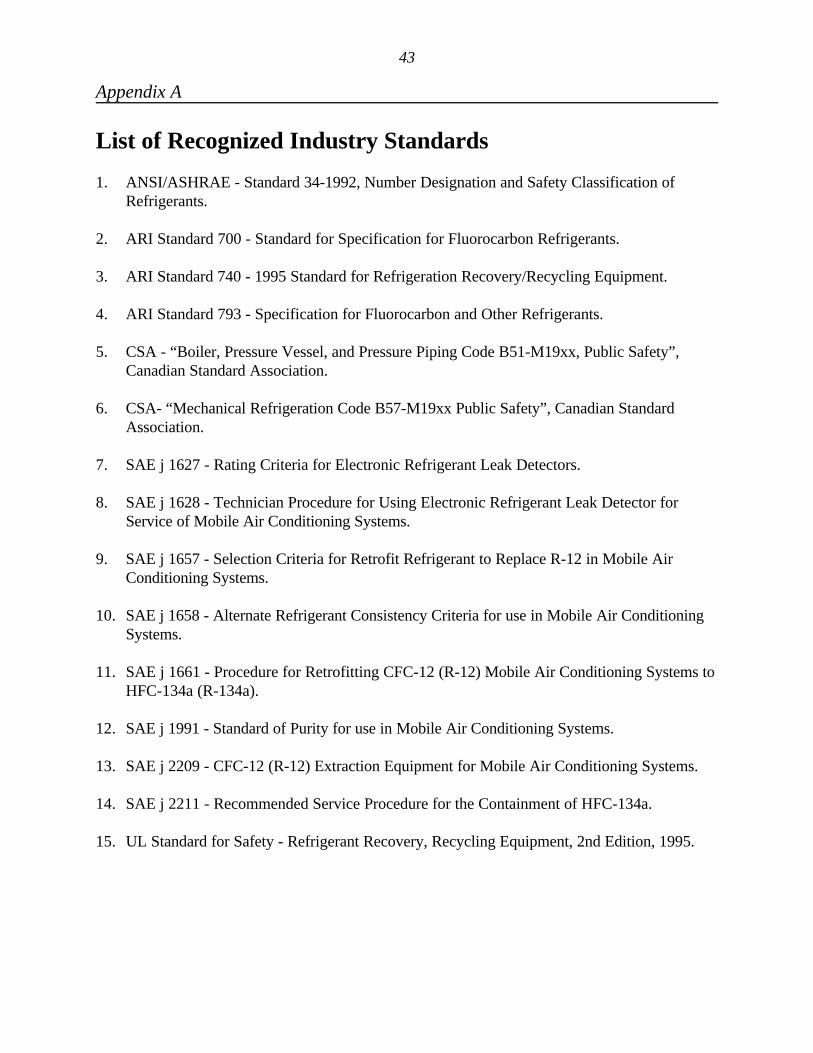
43
Appendix A
List of Recognized Industry Standards
1. ANSI/ASHRAE - Standard 34-1992, Number Designation and Safety Classification ofRefrigerants.
2. ARI Standard 700 - Standard for Specification for Fluorocarbon Refrigerants.
3. ARI Standard 740 - 1995 Standard for Refrigeration Recovery/Recycling Equipment.
4. ARI Standard 793 - Specification for Fluorocarbon and Other Refrigerants.
5. CSA - “Boiler, Pressure Vessel, and Pressure Piping Code B51-M19xx, Public Safety”,Canadian Standard Association.
6. CSA- “Mechanical Refrigeration Code B57-M19xx Public Safety”, Canadian StandardAssociation.
7. SAE j 1627 - Rating Criteria for Electronic Refrigerant Leak Detectors.
8. SAE j 1628 - Technician Procedure for Using Electronic Refrigerant Leak Detector forService of Mobile Air Conditioning Systems.
9. SAE j 1657 - Selection Criteria for Retrofit Refrigerant to Replace R-12 in Mobile AirConditioning Systems.
10. SAE j 1658 - Alternate Refrigerant Consistency Criteria for use in Mobile Air ConditioningSystems.
11. SAE j 1661 - Procedure for Retrofitting CFC-12 (R-12) Mobile Air Conditioning Systems toHFC-134a (R-134a).
12. SAE j 1991 - Standard of Purity for use in Mobile Air Conditioning Systems.
13. SAE j 2209 - CFC-12 (R-12) Extraction Equipment for Mobile Air Conditioning Systems.
14. SAE j 2211 - Recommended Service Procedure for the Containment of HFC-134a.
15. UL Standard for Safety - Refrigerant Recovery, Recycling Equipment, 2nd Edition, 1995.
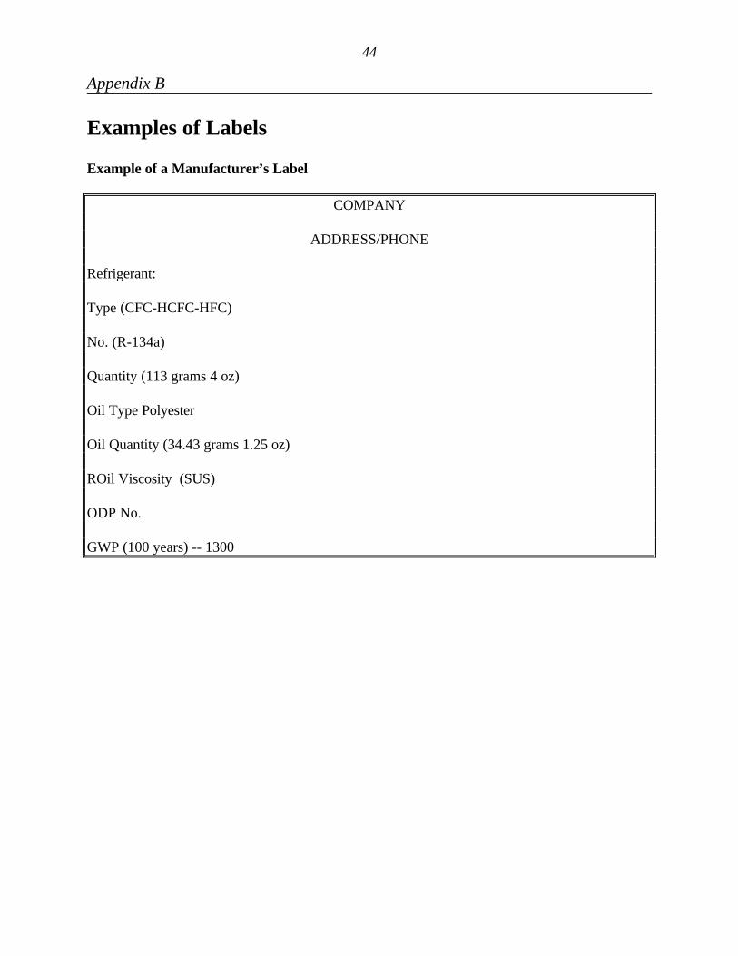
44
Appendix B
Examples of Labels
Example of a Manufacturer’s Label
COMPANY
ADDRESS/PHONE
Refrigerant:
Type (CFC-HCFC-HFC)
No. (R-134a)
Quantity (113 grams 4 oz)
Oil Type Polyester
Oil Quantity (34.43 grams 1.25 oz)
ROil Viscosity (SUS)
ODP No.
GWP (100 years) -- 1300
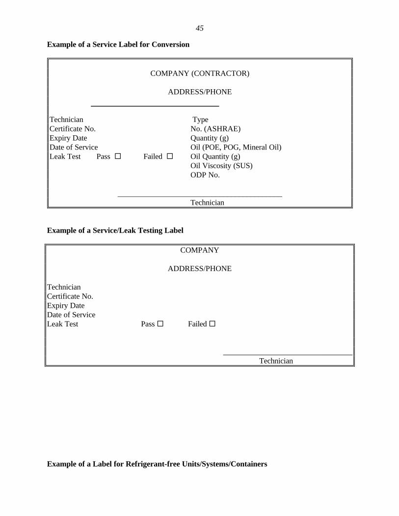
45
Example of a Service Label for Conversion
Example of a Service/Leak Testing Label
COMPANY
ADDRESS/PHONE
TechnicianCertificate No.Expiry DateDate of ServiceLeak Test Pass ¨ Failed ¨
_________________________________ Technician
Example of a Label for Refrigerant-free Units/Systems/Containers
COMPANY (CONTRACTOR)
ADDRESS/PHONE
Technician TypeCertificate No. No. (ASHRAE)Expiry Date Quantity (g)Date of Service Oil (POE, POG, Mineral Oil)Leak Test Pass ¨ Failed ¨ Oil Quantity (g)
Oil Viscosity (SUS)ODP No.
__________________________________________Technician
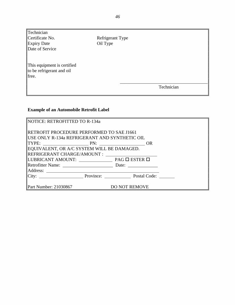
46
TechnicianCertificate No. Refrigerant TypeExpiry Date Oil TypeDate of Service
This equipment is certifiedto be refrigerant and oilfree.
______________________________________ Technician
Example of an Automobile Retrofit Label
NOTICE: RETROFITTED TO R-134a
RETROFIT PROCEDURE PERFORMED TO SAE J1661USE ONLY R-134a REFRIGERANT AND SYNTHETIC OILTYPE: PN: OREQUIVALENT, OR A/C SYSTEM WILL BE DAMAGED.REFRIGERANT CHARGE/AMOUNT : LUBRICANT AMOUNT: PAG o ESTER oRetrofitter Name: Date: Address: City: Province: Postal Code:
Part Number: 21030867 DO NOT REMOVE