entso-e draft network code on high voltage direct current
TRANSCRIPT

1 | P a g e
ENTSO-E AISBL • Avenue Cortenbergh 100 • 1000 Brussels• Belgium• Tel +32 2 741 09 50 • Fax +32 2 741 09 51
ENTSO-E Draft Network Code on High Voltage Direct Current Connections and DC-
connected Power Park Modules
30 April 2014
Notice
This document reflects the work done by ENTSO-E in line with ACER’s framework guidelines on electricity grid connections published on 20 July 2011 and the EC mandate letter received by ENTSO-E on 29 April 2013.
It incorporates the input of an extensive informal and formal dialogue with stakeholders, including meetings, public workshops, a “Call for Stakeholder Input” between 7 May 2013 and 7 June 2013, a formal consultation in accordance with the provisions of the Article 10 of Regulation (EC) N°714/2009 during November and December 2013 aiming at exchanging views on the challenges and key issues. Furthermore, it is based on the outcome of bilateral/ trilateral meetings with ACER and with the European Commission.
This document is now called “Network Code on High Voltage Direct Current Connections and DC-connected Power Park Modules” and is submitted to ACER for ACER’s reasoned opinion pursuant to Article 6 of Regulation (EC) 714/2009.

2 | P a g e
ENTSO-E AISBL • Avenue Cortenbergh 100 • 1000 Brussels• Belgium• Tel +32 2 741 09 50 • Fax +32 2 741 09 51
THE EUROPEAN COMMISSION,
Having regard to the Treaty on the Functioning of the European Union,
Having regard to Directive 2009/72/EC of the European Parliament and of the Council of 13 July 2009 concerning common rules for the internal market in electricity and repealing Directive 2003/54/EC,
Having regard to Regulation (EC) No 713/2009 of the European Parliament and of the Council of 13 July 2009 establishing an Agency for the Cooperation of Energy Regulators (ACER),
Having regard to Regulation (EC) No 714/2009 of the European Parliament and of the Council of 13 July 2009 on conditions for access to the network for cross-border exchanges in electricity and repealing Regulation (EC) No 1228/2003 and especially Article 6,
Having regard to the Framework Guideline on Electricity Grid Connections issued by the Agency for the Coordination of Energy Regulators on 21 July 2011,
Whereas:
(1) Directive 2009/72/EC of the European Parliament and of the Council of 13 July 2009 concerning common rules for the internal market in electricity and repealing Directive 2003/54/EC and Regulation (EC) No 714/2009 of the European Parliament and of the Council of 13 July 2009 underline the need for an increased cooperation and coordination among transmission system operators within a European Network of Transmission System Operators for Electricity (ENTSO‐E) to create Network Codes for providing and managing effective and transparent access to the transmission networks across borders, and to ensure coordinated and sufficiently forward-looking planning and sound technical evolution of the transmission system in the European Union, including the creation of interconnection capacities, with due regard to the environment.
(2) Transmission System Operators (TSO(s)) are according to Article 2 and 12 of Directive2009/72/EC responsible for providing and operating high and extra‐high Voltage networks for long‐distance transmission of electricity as well as for supply of lower‐level regional distribution systems and directly connected customers. Besides this transmission and supply task it is also the TSO(s)’responsibility to ensure the system security with a high level of reliability and quality.
(3) ENTSO-E has drafted this Network Code on HVDC Connections and DC-connected Power Park Modules aiming at setting out clear and objective requirements for HVDC System Owners, DC-connected Power Park Module Owners, Network Operators and National Regulatory Authorities in order to contribute to non-discrimination, effective competition and the efficient functioning of the internal electricity market and to ensure system security.
(4) The technical connection requirements for HVDC Systems refer unless stated otherwise to the AC Connection Points of such systems, and do not address internal DC connection requirements for multi-terminal or meshed systems.
(5) In cases where studies for new HVDC System connections require data and models from other grid users such as large generators, industrial facilities and other DC links, this Network Code allows for the Relevant Network Operator to require such information where reasonable. These studies model the sometimes complex interaction between different grid users, and aim at ensuring adequate power quality performance.
3 | P a g e
ENTSO-E AISBL • Avenue Cortenbergh 100 • 1000 Brussels• Belgium• Tel +32 2 741 09 50 • Fax +32 2 741 09 51
(6) This Network Code has been drafted in accordance with the Article 8(7) of Regulation (EC) N°714/2009 according to which the Network Codes shall be developed for cross-border issues and market integration issues and shall be without prejudice to the right of Member States to establish national network codes which do not affect cross-border trade.
(7) The Network Code provides for various requirements to be defined by the Relevant Network Operators. In those countries where the TSOs are entitled to define – read here to propose to the relevant bodies for its approval – the technical and instrumental operational procedures for the proper technical management of the power system or to give the necessary instructions to other entities, which need to be taken into account to ensure the necessary coordination of the system and maintain the overall system security, the Network Code does not affect the TSO’s competences and responsibilities.
(8) The Network Code provides for agreements by Relevant Network Operators on various technical requirements. In those countries where the TSOs are granted public authority or competence to adopt decisions when defining requirements for connecting Power Generating Modules which have to be taken into account for, and cannot be changed by, any subsequent Connection Agreement with the Relevant Network Operator, this Network Code does not affect the TSO’s decision making powers in those countries.
(9) In case Power Park Modules are connected in small island systems with local demand and non-synchronously operating with the main system via DC-links, the applicability of this code to those PPMs will be defined according to national provisions, taking into account size of the plant, system and local demand, and relevant long-term system development plans. HAS ADOPTED THIS NETWORK CODE:

4 | P a g e
ENTSO-E AISBL • Avenue Cortenbergh 100 • 1000 Brussels• Belgium• Tel +32 2 741 09 50 • Fax +32 2 741 09 51
CONTENTS
CHAPTER 1 GENERAL PROVISIONS ..................................................................................................... 8
Article 1 Subject matter ................................................................................................................. 8
Article 2 Definitions ....................................................................................................................... 8
Article 3 Scope ............................................................................................................................. 11
Article 4 Regulatory aspects ........................................................................................................ 14
Article 5 Recovery of costs ........................................................................................................... 14
Article 6 Confidentiality obligations ............................................................................................ 15
CHAPTER 2 GENERAL REQUIREMENTS FOR HVDC CONNECTIONS .................................................. 16
SECTION 1 REQUIREMENTS FOR ACTIVE POWER CONTROL AND FREQUENCY SUPPORT .......... 16
Article 7 Frequency ranges .......................................................................................................... 16
Article 8 Rate-of-change-of-Frequency withstand capability ...................................................... 17
Article 9 Active Power controllability, control range and ramping rate ...................................... 17
Article 10 Synthetic inertia ............................................................................................................ 18
Article 11 Frequency Sensitive Mode (FSM) .................................................................................. 19
Article 12 Limited Frequency Sensitive Mode Overfrequency (LFSM-O) ...................................... 21
Article 13 Limited Frequency Sensitive Mode Underfrequency (LFSM-U) .................................... 22
Article 14 Frequency Control ......................................................................................................... 23
Article 15 Maximum loss of active power ..................................................................................... 24
SECTION 2 REQUIREMENTS FOR REACTIVE POWER CONTROL AND VOLTAGE SUPPORT .......... 24
Article 16 Voltage ranges ............................................................................................................... 24
Article 17 Short circuit contribution during faults ......................................................................... 25
Article 18 Reactive Power capability ............................................................................................. 26
Article 19 Reactive Power exchanged with the Network .............................................................. 27
Article 20 Reactive Power control mode ....................................................................................... 28
Article 21 Priority to Active or Reactive Power contribution ........................................................ 29
Article 22 Power quality ................................................................................................................. 29
SECTION 3 REQUIREMENTS FOR FAULT RIDE THROUGH ............................................................ 29
Article 23 Fault ride through capability ......................................................................................... 29
Article 24 Post fault Active Power recovery .................................................................................. 31
Article 25 Fast recovery of DC faults .............................................................................................. 31
SECTION 4 REQUIREMENTS FOR CONTROL ................................................................................. 31

5 | P a g e
ENTSO-E AISBL • Avenue Cortenbergh 100 • 1000 Brussels• Belgium• Tel +32 2 741 09 50 • Fax +32 2 741 09 51
Article 26 Converter energisation and synchronisation ................................................................ 31
Article 27 Interaction between HVDC System(s) and/or other plant(s) and equipment .............. 32
Article 28 Power oscillation damping capability ............................................................................ 32
Article 29 Subsynchronous torsional interaction damping capability ........................................... 33
Article 30 Network characteristics ................................................................................................. 33
Article 31 HVDC System robustness .............................................................................................. 33
SECTION 5 REQUIREMENTS FOR PROTECTION DEVICES AND SETTINGS .................................... 34
Article 32 Electrical protection schemes and settings ................................................................... 34
Article 33 Priority ranking of protection and control .................................................................... 34
Article 34 Changes to protection and control schemes and settings ............................................ 35
SECTION 6 REQUIREMENTS FOR POWER SYSTEM RESTORATION .............................................. 35
Article 35 Black start ...................................................................................................................... 35
CHAPTER 3 REQUIREMENTS FOR DC-CONNECTED POWER PARK MODULES AND REMOTE-END
HVDC CONVERTER STATIONS ................................................................................................................ 37
SECTION 1 REQUIREMENTS FOR DC-CONNECTED POWER PARK MODULES .............................. 37
Article 36 Scope ............................................................................................................................. 37
Article 37 Frequency stability requirements ................................................................................. 37
Article 38 Reactive Power and Voltage requirements ................................................................... 39
Article 39 Control Requirements ................................................................................................... 43
Article 40 Network characteristics ................................................................................................. 43
Article 41 Protection requirements ............................................................................................... 44
Article 42 Power Quality ................................................................................................................ 44
Article 43 General System Management Requirements applicable to DC connected PPMs ........ 44
SECTION 2 REQUIREMENTS FOR REMOTE-END HVDC CONVERTER STATIONS .......................... 45
Article 44 Scope ............................................................................................................................. 45
Article 45 Frequency stability requirements ................................................................................. 45
Article 46 Reactive Power and Voltage requirements ................................................................... 45
Article 47 Network characteristics ................................................................................................. 47
Article 48 Power Quality ................................................................................................................ 47
CHAPTER 4 INFORMATION EXCHANGE AND COORDINATION ......................................................... 48
Article 49 Operation ...................................................................................................................... 48
Article 50 Parameter setting .......................................................................................................... 49
Article 51 Fault recording and Monitoring .................................................................................... 49
Article 52 Simulation models ......................................................................................................... 50

6 | P a g e
ENTSO-E AISBL • Avenue Cortenbergh 100 • 1000 Brussels• Belgium• Tel +32 2 741 09 50 • Fax +32 2 741 09 51
CHAPTER 5 OPERATIONAL NOTIFICATION PROCEDURE FOR CONNECTION .................................... 51
Article 53 General provisions ......................................................................................................... 51
Article 54 Energisation Operational Notification (EON) for HVDC Systems .................................. 51
Article 55 Interim Operational Notification (ION) for HVDC Systems ........................................... 51
Article 56 Final Operational Notification (FON) for HVDC Systems ............................................... 52
Article 57 Limited Operational Notification (LON) for HVDC Systems .......................................... 53
Article 58 General provisions ......................................................................................................... 53
Article 59 Energisation Operational Notification (EON) for DC-connected Power Park Modules 54
Article 60 Interim Operational Notification (ION) for DC-connected Power Park Modules .......... 54
Article 61 Final Operational Notification (FON) for DC-connected Power Park Modules ............. 55
Article 62 Limited Operational Notification (LON) for DC-connected Power Park Modules ......... 55
Article 63 Operational Notification Procedure for Existing HVDC Systems ................................... 56
Article 64 Operational Notification Procedure for existing DC-Connected Power Park Modules 58
CHAPTER 6 COMPLIANCE ................................................................................................................. 60
Article 65 Responsibility of the HVDC System Owner and DC-connected Power Park Module
Owner 60
Article 66 Tasks of the Relevant Network Operator ...................................................................... 60
Article 67 Compliance testing for HVDC Systems .......................................................................... 62
Article 68 Compliance testing for DC-connected Power Park Modules and Remote-end HVDC
Converter Units ................................................................................................................................. 65
Article 69 Compliance simulations for HVDC Systems .................................................................. 68
Article 70 Compliance simulations for DC-connected Power Park Modules and Remote-end
HVDC Converter Units ....................................................................................................................... 70
CHAPTER 7 DEROGATIONS ............................................................................................................... 72
Article 71 General Provisions ......................................................................................................... 72
Article 72 Request for Derogation ................................................................................................. 72
Article 73 Decision on Derogation ................................................................................................. 73
Article 74 Compliance of Existing HVDC Systems and Existing DC-connected Power Park Modules
75
Article 75 Register of Derogations to the Network Code .............................................................. 75
CHAPTER 8 FINAL PROVISIONS ......................................................................................................... 76
Article 76 Amendment of contracts and general terms and conditions ....................................... 76
Article 77 HVDC System or DC-connected Power Park Modules connecting with Synchronous
Area(s) or Control Area(s) not bound by EU legislation .................................................................... 76
Article 78 Entry into force .............................................................................................................. 76

7 | P a g e
ENTSO-E AISBL • Avenue Cortenbergh 100 • 1000 Brussels• Belgium• Tel +32 2 741 09 50 • Fax +32 2 741 09 51

8 | P a g e
ENTSO-E AISBL • Avenue Cortenbergh 100 • 1000 Brussels• Belgium• Tel +32 2 741 09 50 • Fax +32 2 741 09 51
CHAPTER 1 GENERAL PROVISIONS
Article 1 Subject matter
1. This Network Code establishes common rules for HVDC Systems and DC-connected Power Park Modules as categorized in Article 3.
2. This Network Code sets up a common framework for Connection Agreements between Network Operators and HVDC System Owners, and between Network Operators and DC-connected Power Park Module Owners.
3. The connection requirements for HVDC Systems as stated in CHAPTER 2 apply, unless stated otherwise, at the AC Connection Point(s) of such systems.
4. The connection requirements for DC-connected Power Park Modules and Remote-end HVDC
Converter Stations as stated in CHAPTER 3 apply, unless stated otherwise, at the Interface
Point of such systems.
5. In Member States where more than one TSO exists, this regulation shall apply to all TSOs
within that Member State. Where a TSO does not have a function relevant to one or some obligations under this Network Code, Member States may under the national regulatory regime provide that the responsibility to comply with one or some obligations under this Network Code is assigned to one or more different TSO. In case of such assignment, the Network Code shall apply accordingly to the TSO(s) to which responsibility have been assigned.
Article 2 Definitions
1. For the purpose of this Network Code, the definitions in Article 2 of Regulation (EC) N° 714/2009, and in Commission Regulations establishing Network Codes that have been adopted according to Article 6(11) of Regulation (EC) N°714/2009, as well as in Article 2 of Directive 2009/72/EC, shall apply.
2. Furthermore, the following definitions shall apply:
DC-connected Power Park Module means a Power Park Module that is connected via one or
more Interface Point(s) to one or more HVDC System(s). Unless otherwise stated, Power Park
Module referred to in this network code means a DC-connected Power Park Module;
DC-connected Power Park Module Owner means a natural or legal entity owning a DC-
connected Power Park Module;
Embedded HVDC System means a HVDC System connected within a Synchronous Area or
within a Control Area that is not installed for the purpose of connecting a DC-connected
Power Park Module at the time of installation, nor installed for the purpose of connecting a
Demand Facility;

9 | P a g e
ENTSO-E AISBL • Avenue Cortenbergh 100 • 1000 Brussels• Belgium• Tel +32 2 741 09 50 • Fax +32 2 741 09 51
Existing HVDC System means an HVDC System which is not a New HVDC System;
Existing DC-connected Power Park Module means a DC-connected Power Park Module
which is not a New DC-connected Power Park Module;
Grid User means the System User using the transmission or distribution system, as identified
in this Network Code in relevant requirements. The term means any System User (other than
the Relevant Network Operator or Relevant TSO) to whom the requirement applies;
HVDC System Maximum Current means the highest phase Current, associated with an
operating point inside the U-Q/Pmax-profile of the HVDC Converter Station at Maximum
HVDC Active Power Transmission Capacity;
HVDC Converter Station means part of an HVDC System which consists of one or more HVDC
Converter Units installed in a single location together with buildings, reactors, filters, reactive
power devices, control, monitoring, protective, measuring and auxiliary equipment;
HVDC Converter Unit means a unit comprising one or more converter bridges, together with
one or more converter transformers, reactors, converter unit control equipment, essential
protective and switching devices and auxiliaries, if any, used for the conversion;
HVDC System means an electrical power system which transfers energy in the form of high-
voltage direct current between two or more AC buses. A HVDC System comprises at least
two HVDC Converter Stations with DC transmission lines or cables between the HVDC
Converter Stations. In case of a back-to-back system the HVDC System comprises only one
HVDC Converter Station with direct DC circuit connection between the pair of HVDC
Converter Units. A HVDC System has at least two Interface Points;
HVDC System Owner means a natural or legal entity owning a HVDC System;
Interface Point means an AC point in a Network connecting equipment owned by two or
more parties (which can be the owner of a Power Generating Module, Demand Facility,
Distribution Network or HVDC System) at which technical specifications affecting the
performance of the equipment of one or more parties can be prescribed;
Maximum HVDC Active Power Transmission Capacity means the maximum continuous
Active Power which an HVDC System can exchange with the Network at each Connection
Point as defined in the Connection Agreement or as agreed between the Relevant Network
Operator and the HVDC System Owner. It is also referred to in this Network Code as Pmax;
Minimum HVDC Active Power Transmission Capacity means the minimum continuous
Active Power which an HVDC System can exchange with the Network at each Connection
Point as defined in the Connection Agreement or as agreed between the Relevant Network
Operator and the HVDC System Owner. It is also referred to in this Network Code as Pmin;
New HVDC System means a HVDC System for which

10 | P a g e
ENTSO-E AISBL • Avenue Cortenbergh 100 • 1000 Brussels• Belgium• Tel +32 2 741 09 50 • Fax +32 2 741 09 51
with regard to the provisions of the initial version of this Network code, a final and
binding contract of purchase of the main plant has been signed after the day which is
two years after the day of the entry into force of this Network Code, or,
with regard to the provisions of the initial version of this Network code, no
confirmation is provided by the HVDC System Owner, with a delay not exceeding
thirty months as from the day of entry into force of this Network Code, that a final
and binding contract of purchase of the main plant exists prior to the day which is
two years after the day of the entry into force of this Network Code, or,
with regard to the provisions of any subsequent amendment to this Network Code, a
final and binding contract of purchase of the main plant has been signed after the
day which is two years after the entry into force of any subsequent amendment to
this Network Code;
New DC-connected Power Park Module means a DC-connected Power Park Module for
which
with regard to the provisions of the initial version of this Network code, a final and
binding contract of purchase of the main plant has been signed after the day which is
two years after the day of the entry into force of this Network Code, or,
with regard to the provisions of the initial version of this Network code, no
confirmation is provided by the DC-connected Power Park Module Owner, with a
delay not exceeding thirty months as from the day of entry into force of this Network
Code, that a final and binding contract of purchase of the main plant exists prior to
the day which is two years after the day of the entry into force of this Network Code,
or,
with regard to the provisions of any subsequent amendment to this Network Code
and/or after any change of thresholds pursuant to the re-assessment procedure of
Article 3(6) in [NC RfG], a final and binding contract of purchase of the main plant has
been signed after the day which is two years after the entry into force of any
subsequent amendment to this Network Code and/or after the entry into force of
any change of thresholds pursuant to the re-assessment procedure;
Remote-end HVDC Converter Station means a HVDC Converter Station which is
synchronously connected via Interface Point(s) to DC-connected Power Park Module(s). For
the purpose of this Network Code, in case of back-to-back schemes the requirements for the
Remote-end HVDC Converter Station apply at the Interface Point(s) with the DC-connected
PPM(s);
Remote-end HVDC Converter Station Owner means a natural or legal entity owning a
Remote-end HVDC Converter Station.
11 | P a g e
ENTSO-E AISBL • Avenue Cortenbergh 100 • 1000 Brussels• Belgium• Tel +32 2 741 09 50 • Fax +32 2 741 09 51
Article 3 Scope
1. HVDC Systems which are within the scope of this Network Code are categorized as follows:
(a) HVDC Systems connecting Synchronous Areas or Control Areas, including back to back schemes;
(b) HVDC Systems connecting Power Park Modules to a Transmission Network or a Distribution Network, pursuant to paragraph 2;
(c) Embedded HVDC Systems within one Control Area and connected to the Transmission Network; and
(d) Embedded HVDC Systems within one Control Area and connected to the Distribution Network when a cross-border impact is demonstrated by the Relevant TSO, while respecting the provisions of Article 4(3). The Relevant TSO shall consider the long-term development of the Network in this assessment.
2. The application of this Network Code for Power Park Modules connected to a Transmission Network or Distribution Network which is not part of a Synchronous Area shall be defined by the Relevant Network Operator in coordination with the Relevant TSO, while respecting the provisions of Article 4(3). All other Power Park Modules which are AC collected but are DC connected to a Synchronous Area are considered DC-connected Power Park Modules and are within the scope of this Network Code.
3. Article 22, Article 27, Article 29 and Article 48, addressing contribution of data and studies, apply to Existing Power Generating Modules, Existing Distribution Networks, Existing Demand Facilities and Existing HVDC Systems.
4. The requirements set forth by this Network Code shall apply to New HVDC Systems and New DC-connected Power Park Modules which are within the scope of this Network Code unless otherwise provided for in this Network Code.
5. With regards to the Embedded HVDC Systems within one Control Area referred to in
paragraphs 1(c) and (d) above, when they fall into one of the categories listed below:
i. HVDC Systems with at least one HVDC Converter Station owned by the
Relevant TSO;
ii. HVDC Systems owned by an entity which exercises control over the Relevant
TSO; or
iii. HVDC Systems owned by an entity directly or indirectly controlled by an
entity which also exercises control over the Relevant TSO,
the following shall apply:
a. The provisions of Article 53 to Article 57, Article 65 to Article 70, and Article
76 do not apply; and
b. The HVDC System Owner shall ensure that the HVDC System is compliant
with the requirements under Article 7 to Article 35, Article 49 and Article 51.
This compliance shall be maintained throughout the lifetime of the facility.
6. Without prejudice to the provisions of Article 3(3) and Article 3(9), other requirements set
forth in this Network Code shall apply to Existing HVDC Systems and Existing DC-connected

12 | P a g e
ENTSO-E AISBL • Avenue Cortenbergh 100 • 1000 Brussels• Belgium• Tel +32 2 741 09 50 • Fax +32 2 741 09 51
Power Park Modules which are within the scope of this Network Code only to the extent this has been decided by the Relevant National Regulatory Authority pursuant to Article 63 and Article 64.
7. With regard to HVDC Systems not yet connected to the Network:
(a) Within a delay not exceeding thirty months as from the day of entry into force of this
Network Code, the HVDC System Owner shall provide the Relevant TSO with a
confirmation of final and binding contracts it has concluded for the construction,
assembly or purchase of the main plant of a HVDC System with relevance to the
provisions of this Network Code and which exists prior to the day, which is two years
after the day of entry into force of this Network Code.
(b) The confirmation shall at least state the contract title, its date of signature and of
entry into force, and the specifications of the main plant to be constructed,
assembled or purchased.
(c) The Relevant TSO may demand that the National Regulatory Authority confirms the
existence, relevance and finality of such a contract, i.e. that its material terms can no
longer be changed by one of the parties to the contract unilaterally and that no party
to the contract has the right to terminate it at will. The HVDC System Owner shall
supply the National Regulatory Authority with all documents the National Regulatory
Authority requests in order to ascertain that a binding and final contract exists.
(d) The HVDC System shall be considered as an Existing HVDC System, provided that:
i. In accordance with Article 3(7) (a) and (b) above, the Relevant TSO is
provided with sufficient evidence of the existence of binding and final
contracts for the construction, assembly or purchase of the main plant of a
HVDC System prior to the day, which is two years after the day of entry into
force of this Network Code; or
ii. Following the verification performed by the National Regulatory Authority in
accordance with Article 3(7) (c), it is ascertained that binding and final
contracts for the construction, assembly or purchase of the main plant of a
HVDC System exist prior to the day, which is two years after the day of entry
into force of this Network Code.
(e) In case the HVDC System Owner does not provide the Relevant TSO with the confirmation within the delay set forth in Article 3(7) (a), the HVDC System shall be considered as a New HVDC System.
8. With regard to DC-connected Power Park Modules not yet connected to the Network:
(a) Within a delay not exceeding thirty months as from the day of entry into force of this
Network Code, the DC-connected Power Park Module Owner shall provide the
Relevant TSO with a confirmation of final and binding contracts it has concluded for
the construction, assembly or purchase of the main plant of the DC-connected Power
Park Module and/or the HVDC System(when the HVDC System Owner is the same as
the DC-connected Power Park Module Owner and is built as part of the development
of the DC-connected Power Park Module) with relevance to the provisions of this
Network Code and which exists prior to the day, which is two years after the day of
entry into force of this Network Code.

13 | P a g e
ENTSO-E AISBL • Avenue Cortenbergh 100 • 1000 Brussels• Belgium• Tel +32 2 741 09 50 • Fax +32 2 741 09 51
(b) The confirmation shall at least state the contract title, its date of signature and of
entry into force, and the specifications of the main plant to be constructed,
assembled or purchased.
(c) The Relevant TSO may demand that the National Regulatory Authority confirms the
existence, relevance and finality of such a contract, i.e. that its material terms can no
longer be changed by one of the parties to the contract unilaterally and that no party
to the contract has the right to terminate it at will. The DC-connected Power Park
Module Owner shall supply the National Regulatory Authority with all documents the
National Regulatory Authority requests in order to ascertain that a binding and final
contract exists.
(d) The DC-connected Power Park Module shall be considered as an Existing DC-
connected Power Park Module, provided that:
i. In accordance with Article 3(8)(a) and (b) above, the Relevant TSO is
provided with sufficient evidence of the existence of binding and final
contracts for the construction, assembly or purchase of the main plant of a
DC-connected Power Park Module and/or where applicable the HVDC
System prior to the day, which is two years after the day of entry into force
of this Network Code; or
ii. Following the verification performed by the National Regulatory Authority in
accordance with Article 3(8)(c), it is ascertained that binding and final
contracts for the construction, assembly or purchase of the main plant of a
DC-connected Power Park Module and where applicable the HVDC System
exist prior to the day, which is two years after the day of entry into force of
this Network Code.
(e) In case the DC-connected Power Park Module Owner does not provide the Relevant
TSO with the confirmation within the delay set forth in Article 3(8)(a), the DC-
connected Power Park Module and as applicable HVDC System shall be considered as
a New DC-connected Power Park Module and/or HVDC System.
9. All HVDC System Owners and DC-connected Power Park Module Owners, existing and new, shall fulfil the following requirements related to equipment development, modernisation and replacement: a) An HVDC System Owner or DC-connected Power Park Module Owner intending to develop,
modernise or replace a part of a HVDC System, HVDC Converter Station, HVDC Converter Unit or DC-connected Power Park Module in a way that may have an impact on its performance and ability to meet the requirements of this Network Code shall notify the Relevant Network Operator(s). The notification shall take place in advance and in accordance with national timescales defined, while respecting the provisions of Article 4(3).
b) The HVDC System Owner or DC-connected Power Park Module shall, while respecting the provisions of Article 4(3), agree with the Relevant Network Operator on these requirements before the proposals are implemented. In case of modernisation or replacement of equipment in existing or new HVDC Systems, HVDC Converter Stations and DC-connected Power Park Modules, the equipment shall comply with the requirements which are relevant to the planned work.

14 | P a g e
ENTSO-E AISBL • Avenue Cortenbergh 100 • 1000 Brussels• Belgium• Tel +32 2 741 09 50 • Fax +32 2 741 09 51
c) While respecting the provisions of Article 4(3), the use of existing spare components for the purpose of development and modernization that do not comply with the requirements has to be agreed with the Relevant Network Operator in each case.
Article 4 Regulatory aspects
1. The requirements established in this Network Code and their applications are based on the principle of non-discrimination and transparency as well as the principle of optimisation between the highest overall efficiency and lowest total cost for all involved parties.
2. Notwithstanding the above, the application of the non-discrimination principle and the principle of optimization between the highest overall efficiency and lowest total costs for all involved parties shall be balanced with the aim of achieving the maximum transparency in issues of interest for the market and the assignment to the real originator of the costs.
3. Where reference is made to this paragraph, the terms and conditions for connection and access to networks or their methodologies shall be established by the National Regulatory Authorities, or by the Member States in accordance with the rules of national law implementing Directive 2009/72/EC, and with the principles of transparency, proportionality and non-discrimination.
4. Any decision by a Network Operator other than the Relevant TSO and any agreement between a Network Operator other than the Relevant TSO and either a DC-connected Power Park Module Owner or a HVDC System Owner shall be exercised in compliance with and respecting the Relevant TSO’s responsibility to ensure system security according to national legislation. Further details to ensure this principle may be specified either by national legislation, or by agreements between the Relevant TSO and the Network Operators in its Control Area, as the case may be.
5. The allocation of tasks between the Relevant Network Operators, as well as the legal framework under which they determine the grid connection requirements under this Network Code, are established pursuant to this Network Code. TSO(s) granted public authority or competence according to national law can adopt decisions when defining requirements under this Network Code while respecting Directive 2009/72/EC.
6. Any decision or agreement adopted pursuant to this Network Code and affecting more than one Member State shall be coordinated among the concerned TSOs and NRAs.
Article 5
Recovery of costs
1. The costs related to the obligations referred to in this Network Code which have to be borne by regulated Network Operators shall be assessed by National Regulatory Authorities.
2. Costs assessed as efficient, reasonable and proportionate shall be recovered as determined by National Regulatory Authorities.

15 | P a g e
ENTSO-E AISBL • Avenue Cortenbergh 100 • 1000 Brussels• Belgium• Tel +32 2 741 09 50 • Fax +32 2 741 09 51
3. If requested by National Regulatory Authorities, regulated Network Operators shall, within three months of such a request, use best endeavours to provide such additional information as reasonably requested by National Regulatory Authorities to facilitate the assessment of the costs incurred.
Article 6 Confidentiality obligations
1. Each Relevant TSO, DSO, HVDC System Owner or DC-connected Power Park Module Owner shall preserve the confidentiality of the information and data submitted to them in fulfilment of the obligations under this Network Code and shall use them exclusively for the purpose they have been submitted in compliance with the Network Code, notably to verify the compliance of requirements set forth in this Network Code.
2. Notwithstanding the above, disclosure of such information and data may occur in case a Relevant Network Operator or a Relevant TSO is compelled under EU or national law to disclose it, under the conditions set forth in the relevant legislation. The disclosure shall be reported to the owner of such information and data.
3. Without prejudice to the obligation to preserve the confidentiality of commercially sensitive information obtained in the course of carrying out its activities, each TSO shall provide to the operator of any other transmission system with which its system is interconnected, sufficient information to ensure the secure and efficient operation, coordinated development and interoperability of the interconnected system.
4. In case of disclosure for other purposes than those described in Article 6(1) and/or 6(2), a Relevant Network Operator or Relevant TSO shall seek the consent of the owner of such information and data. This consent shall not be unreasonably withheld.

16 | P a g e
ENTSO-E AISBL • Avenue Cortenbergh 100 • 1000 Brussels• Belgium• Tel +32 2 741 09 50 • Fax +32 2 741 09 51
CHAPTER 2 GENERAL REQUIREMENTS FOR HVDC CONNECTIONS
SECTION 1 REQUIREMENTS FOR ACTIVE POWER CONTROL AND FREQUENCY SUPPORT
Article 7 Frequency ranges
1. A HVDC System shall fulfil the following requirements referring to Frequency stability:
(a) An HVDC System shall be capable of staying connected to the Network and remaining
operable within the Frequency ranges and time periods specified by Table 1, for the short circuit power range as specified in Article 30(1)b.
(b) While respecting the provisions of Article 4(3), wider Frequency ranges or longer minimum times for operation can be agreed between the Relevant TSO and the HVDC System Owner if needed to preserve or to restore system security. If wider Frequency ranges or longer minimum times for operation are economically and technically feasible, the consent of the HVDC System Owner shall not be unreasonably withheld.
(c) Notwithstanding Article 7(1)(a) above, a HVDC System shall be capable of automatic disconnection at specified Frequencies.
(d) The Relevant TSO shall have the right to specify a maximum admissible Active Power output reduction from its operating point if the system Frequency falls below 49 Hz, while respecting the provisions of Article 4(3).

17 | P a g e
ENTSO-E AISBL • Avenue Cortenbergh 100 • 1000 Brussels• Belgium• Tel +32 2 741 09 50 • Fax +32 2 741 09 51
Frequency range Time period for operation
47.0 Hz – 47.5 Hz 60 seconds
47.5 Hz – 48.5 Hz
To be defined by each Relevant TSO while respecting the provisions of Article 4(3), but longer than defined times for generation and demand according to [NC RfG] and [DCC] respectively, and longer than for DC-connected
PPMs according to Article 37
48.5 Hz – 49.0 Hz
To be defined by each Relevant TSO while respecting the provisions of Article 4(3), but longer than defined times for generation and demand according to [NC RfG] and [DCC] respectively, and longer than for DC-connected
PPMs according to Article 37
49.0 Hz – 51.0 Hz Unlimited
51.0 Hz – 51.5 Hz
To be defined by each Relevant TSO while respecting the provisions of Article 4(3), but longer than defined times for generation and demand according to [NC RfG] and [DCC] respectively, and longer than for DC-connected
PPMs according to Article 37
51.5 Hz – 52.0 Hz To be defined by each Relevant TSO while respecting the
provisions of Article 4(3) and longer than for DC-connected PPMs according to Article 37
Table 1: This table shows the minimum time periods an HVDC System shall be able to operate for different Frequencies deviating from a nominal value without disconnecting from the Network.
Article 8 Rate-of-change-of-Frequency withstand capability
With regard to the rate of change of Frequency withstand capability, a HVDC System shall be capable of staying connected to the Network and operable if the Network Frequency changes at a rate between -2.5 and +2.5 Hz/s (measured at any point in time as an average of the rate of change of Frequency for the previous 1s).
Article 9 Active Power controllability, control range and ramping rate
1. With regard to the capability of controlling the transmitted Active Power:
(a) The HVDC System shall be capable of adjusting the transmitted Active Power up to the Maximum HVDC Active Power Transmission Capacity of the HVDC System in each direction following an Instruction from the Relevant TSO(s).
i. The Relevant TSO(s) shall have the right to specify, while respecting the provisions of Article 4(3), a maximum and minimum power step size for adjusting the transmitted Active Power.

18 | P a g e
ENTSO-E AISBL • Avenue Cortenbergh 100 • 1000 Brussels• Belgium• Tel +32 2 741 09 50 • Fax +32 2 741 09 51
ii. The Relevant TSO(s) shall have the right, while respecting the provisions of Article 4(3) to define a Minimum HVDC Active Power Transmission Capacity for each direction, below which Active Power transmission capability is not requested.
iii. The maximum delay within which the HVDC System shall be capable of adjusting the
transmitted Active Power upon receipt of request from the Relevant TSO(s) shall be defined by the Relevant TSO, while respecting the provisions of Article 4(3).
(b) In case of Disturbance in one or more of the connecting AC Networks, the HVDC System shall be capable of modifying the transmitted Active Power in accordance with regulation sequences defined by the Relevant TSO, while respecting the provisions of Article 4(3). This shall be achieved as fast as technically feasible with an initial delay as short as possible. If the initial delay prior to the start of the change is greater than 10 milliseconds from receiving the triggering signal sent by the Relevant TSO(s), it shall be reasonably justified by the HVDC System Owner to the Relevant TSO(s).
(c) The Relevant TSO(s) shall have the right, while respecting the provisions of Article 4(3) to require the HVDC System to be capable of fast Active Power reversal. The power reversal shall be possible from the Maximum Active Power Transmission Capacity in one direction to the Maximum Active Power Transmission Capacity in the other direction as fast as technically feasible and reasonably justified by the HVDC System Owner to the Relevant TSOs if greater than 2 seconds.
(d) For HVDC Systems linking various Control Areas or Synchronous Areas, the HVDC System
shall be equipped with control functions enabling the Relevant TSO(s) to modify the
transmitted Active Power in order to perform cross-border Exchange and Sharing of
Frequency Containment Reserve, Frequency Restoration Reserve, Replacement Reserve and
to activate Imbalance Netting Power Interchange as required in [NC LFC&R].
2. With regard to the capability of controlling ramping rate, the HVDC System shall be capable of
adjusting the ramping rate of Active Power variations within its technical capabilities in
accordance with Instructions sent by the Relevant TSO(s). In case of modification of Active Power
according to Article 9(1) (b) and (c), ramping rate adjustment shall be inhibited.
3. The Relevant TSO shall have the right to require, while respecting the provisions of Article 4(3), in coordination with adjacent TSO(s), that the control functions of a HVDC System shall be capable of taking automatic remedial actions including, but not limited to, stopping the ramping and blocking FSM, LFSM-O, LFSM-U and Frequency control. The triggering and blocking criteria shall be defined by the Relevant TSO(s) and subject to notification to the National Regulatory Authority. The modalities of that notification shall be determined in accordance with the applicable national regulatory framework.
Article 10 Synthetic inertia
1. With regard to the capability of providing Synthetic Inertia in response to a rate of change of Frequency:
(a) The Relevant TSO shall have the right to require that a HVDC System shall be capable of providing Synthetic Inertia in response to Frequency changes, activated in low and/or high Frequency regimes by rapidly adjusting the Active Power injected to or withdrawn from the AC Network in order to limit the rate of change of Frequency, while respecting the provisions

19 | P a g e
ENTSO-E AISBL • Avenue Cortenbergh 100 • 1000 Brussels• Belgium• Tel +32 2 741 09 50 • Fax +32 2 741 09 51
of Article 4(3) of this Network Code and at least accounting for the results of the studies as specified in Article 15(8)c) of [NC OS].
(b) The principle of this control system and the associated performance parameters shall be agreed between the Relevant TSO and the HVDC System Owner while respecting the provisions of Article 4(3).
Article 11 Frequency Sensitive Mode (FSM)
1. When operating in Frequency Sensitive Mode (FSM),the following shall apply:
(a) The HVDC System shall be capable of responding to Frequency deviations in each connected AC Network by adjusting the Active Power transmission as indicated in Figure 1 and in accordance with the parameters specified by each TSO within the ranges shown in Table 2. This specification shall be subject to notification to the National Regulatory Authority. The modalities of that notification shall be determined in accordance with the applicable national regulatory framework.
(b) The adjustment of Active Power Frequency Response is limited by the Minimum HVDC Active Power Transmission Capacity and Maximum HVDC Active Power Transmission Capacity of the HVDC System (in each direction).
Figure 1: Active Power Frequency Response capability of a HVDC System in FSM illustrating the case of zero
deadband and insensitivity with a positive Active Power Setpoint (import mode). P is the change in Active Power output from the HVDC System. fn is the target Frequency in the AC Network where the FSM service is
provided and f is the Frequency deviation in the AC Network where the FSM service is provided.

20 | P a g e
ENTSO-E AISBL • Avenue Cortenbergh 100 • 1000 Brussels• Belgium• Tel +32 2 741 09 50 • Fax +32 2 741 09 51
Parameters Ranges
Frequency Response Deadband 0 – ±500mHz
Droop s1 (upward regulation) Minimum 0.1%
Droop s2 (downward regulation) Minimum 0.1%
Frequency Response Insensitivity Maximum 30 mHz
Table 2: Parameters for Active Power Frequency Response in FSM
(c) The HVDC System shall be capable, following an Instruction from the Relevant TSO, of
adjusting the Droops for upward and downward regulation, the Frequency Response Deadband and the operational range of variation within the Active Power range available for FSM, defined in Figure 1 and more generally within the limits set by Article 11 (1) (a) and (b). These values shall be subject to notification to the National Regulatory Authority. The modalities of that notification shall be determined in accordance with the applicable national regulatory framework.
(d) As a result of a Frequency step change, the HVDC System shall be capable of adjusting Active Power to the Active Power Frequency response defined in Figure 1, such that the response is
i. as fast as inherently technically feasible; and
ii. at or above the solid line according to Figure 2 in accordance with the parameters specified by each Relevant TSO within the ranges according to Table 3:
- The HVDC System shall be able to adjust Active Power Output P up to the limit of the Active Power range requested by the Relevant TSO in accordance with the times t1 and t2 according to the ranges in Table 3, where t1 is the initial delay and t2 is the time for full activation. The values of t1and t2 shall be specified by the Relevant TSO, subject to notification to the National Regulatory Authority. The modalities of that notification shall be determined in accordance with the applicable national regulatory framework.
- The initial delay of activation shall be as short as possible. If greater than 0.5 second, the initial delay of activation shall be reasonably justified by the HVDC System Owner to the Relevant TSO and shall be subject to approval by the Relevant TSO, while respecting the provisions of Article 4(3).

21 | P a g e
ENTSO-E AISBL • Avenue Cortenbergh 100 • 1000 Brussels• Belgium• Tel +32 2 741 09 50 • Fax +32 2 741 09 51
Figure 2: Active Power Frequency Response capability of a HVDC System. P is the change in Active Power triggered by the step change in Frequency.
Parameters Time
Maximum admissible initial delay 0.5 seconds
Maximum admissible time for full activation , unless longer
activation times are specified by the Relevant TSO 30 seconds
Table 3: Parameters for full activation of Active Power Frequency Response resulting from Frequency step change.
(e) For HVDC Systems linking various Control Areas or Synchronous Areas, in Frequency Sensitive Mode operation the HVDC System shall be capable of adjusting full Active Power Frequency Response at any time and for a continuous time period.
(f) As long as a Frequency deviation continues Active Power control shall not have any adverse impact on the Active Power Frequency Response.
Article 12 Limited Frequency Sensitive Mode Overfrequency (LFSM-O)
1. In addition to Article 11 the following shall apply cumulatively with regard to Limited Frequency Sensitive Mode – Overfrequency (LFSM-O):
(a) The HVDC System shall be capable of adjusting Active Power exchange with the AC
Network(s), during both import and export, according to Figure 3 at a Frequency threshold f1 between and including 50.2 Hz and 50.5 Hz with a Droop S3 adjustable from 0.1 % upwards. In the LFSM-O mode the HVDC System shall be capable of adjusting power down to its
max
1
P
P
st
maxP
P
1t
2t
1t
2t
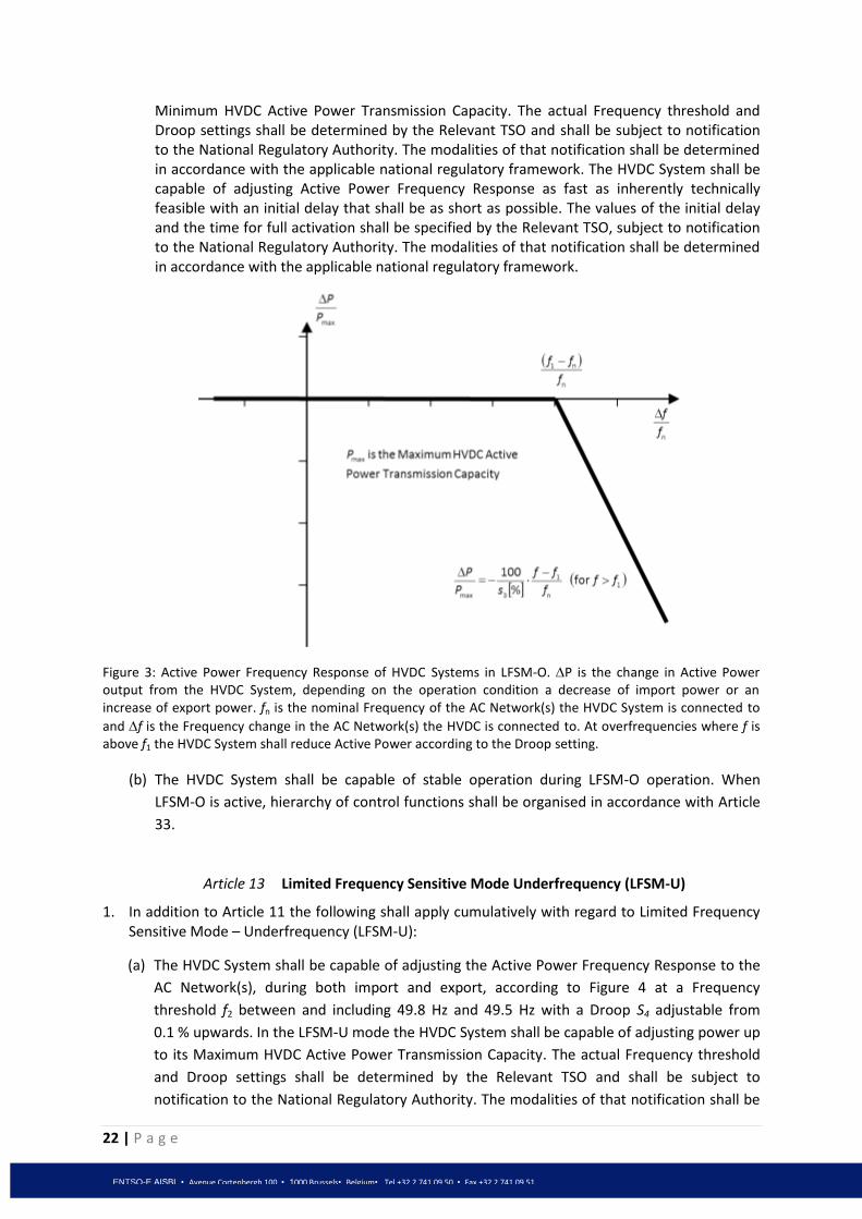
22 | P a g e
ENTSO-E AISBL • Avenue Cortenbergh 100 • 1000 Brussels• Belgium• Tel +32 2 741 09 50 • Fax +32 2 741 09 51
Minimum HVDC Active Power Transmission Capacity. The actual Frequency threshold and Droop settings shall be determined by the Relevant TSO and shall be subject to notification to the National Regulatory Authority. The modalities of that notification shall be determined in accordance with the applicable national regulatory framework. The HVDC System shall be capable of adjusting Active Power Frequency Response as fast as inherently technically feasible with an initial delay that shall be as short as possible. The values of the initial delay and the time for full activation shall be specified by the Relevant TSO, subject to notification to the National Regulatory Authority. The modalities of that notification shall be determined in accordance with the applicable national regulatory framework.
Figure 3: Active Power Frequency Response of HVDC Systems in LFSM-O. P is the change in Active Power output from the HVDC System, depending on the operation condition a decrease of import power or an increase of export power. fn is the nominal Frequency of the AC Network(s) the HVDC System is connected to
and f is the Frequency change in the AC Network(s) the HVDC is connected to. At overfrequencies where f is above f1 the HVDC System shall reduce Active Power according to the Droop setting.
(b) The HVDC System shall be capable of stable operation during LFSM-O operation. When
LFSM-O is active, hierarchy of control functions shall be organised in accordance with Article
33.
Article 13 Limited Frequency Sensitive Mode Underfrequency (LFSM-U)
1. In addition to Article 11 the following shall apply cumulatively with regard to Limited Frequency Sensitive Mode – Underfrequency (LFSM-U):
(a) The HVDC System shall be capable of adjusting the Active Power Frequency Response to the
AC Network(s), during both import and export, according to Figure 4 at a Frequency
threshold f2 between and including 49.8 Hz and 49.5 Hz with a Droop S4 adjustable from
0.1 % upwards. In the LFSM-U mode the HVDC System shall be capable of adjusting power up
to its Maximum HVDC Active Power Transmission Capacity. The actual Frequency threshold
and Droop settings shall be determined by the Relevant TSO and shall be subject to
notification to the National Regulatory Authority. The modalities of that notification shall be

23 | P a g e
ENTSO-E AISBL • Avenue Cortenbergh 100 • 1000 Brussels• Belgium• Tel +32 2 741 09 50 • Fax +32 2 741 09 51
determined in accordance with the applicable national regulatory framework. The Active
Power Frequency Response shall be activated as fast as inherently technically feasible with
an initial delay that shall be as short as possible. The values of the initial delay and the time
for full activation shall be specified by the Relevant TSO, subject to notification to the
National Regulatory Authority. The modalities of that notification shall be determined in
accordance with the applicable national regulatory framework.
Figure 4: Active Power Frequency Response capability of HVDC Systems in LFSM-U. P is the change in Active Power output from the HVDC System, depending on the operation condition a decrease of import power or an increase of export power. fn is the nominal Frequency in the AC Network(s) the HVDC System is connected and
f is the Frequency change in the AC Network(s) the HVDC is connected. At underfrequencies where f is below f2, the HVDC System has to increase Active Power output according to the Droop s4.
(b) The HVDC System shall be capable of stable operation during LFSM-U operation. When LFSM-
U is active, hierarchy of control functions shall be organised in accordance with Article 33.
Article 14 Frequency Control
1. With regard to the capability of providing additional Frequency Control to those defined in
Articles 11, 12 and 13:
(a) The Relevant TSO(s) shall have the right to require, while respecting the provisions of Article
4(3), that a HVDC System shall be equipped with an independent control mode to modulate
the Active Power output of the HVDC Converter Station depending on the Frequencies at all
Connection Points of the HVDC System in order to maintain stable system Frequencies.
(b) The operating principle, the associated performance parameters and the activation criteria of
this Frequency Control shall be defined by the Relevant TSO(s) while respecting the
provisions of Article 4(3).

24 | P a g e
ENTSO-E AISBL • Avenue Cortenbergh 100 • 1000 Brussels• Belgium• Tel +32 2 741 09 50 • Fax +32 2 741 09 51
Article 15 Maximum loss of active power
1. The HVDC System shall be configured such that its loss of Active Power injection in a
Synchronous Area, shall be limited to a value defined by the Relevant TSOs for their respective
LFC Block, based on its impact on the system and while respecting the provisions of Article 4(3).
2. Where the HVDC System connects two or more LFC Blocks, the Relevant TSOs shall consult each
other in order to set a coordinated value of the maximum loss of Active Power injection as
referred to in Article 15(1) above, taking into account common mode failures.
SECTION 2 REQUIREMENTS FOR REACTIVE POWER CONTROL AND VOLTAGE SUPPORT
Article 16 Voltage ranges
1. HVDC Converter Stations shall be capable of fulfilling the following requirements with regard to steady state Voltage ranges: (a) Notwithstanding the provisions of Article 23, a HVDC Converter Station shall be capable of
staying connected to the Network and capable of operating at HVDC System Maximum Current, within the ranges of the Network Voltage at the Connection Point, expressed by the Voltage at the Connection Point related to nominal Voltage (per unit), and the time periods specified by Table 4 or Table 5. The establishment of the reference nominal Voltage shall be subject to coordination between the adjacent Relevant Network Operator(s), while respecting the provisions of Article 4(3).
Synchronous Area Voltage Range Time period for operation
Continental Europe
0.85 pu – 1.118 pu Unlimited
1.118 pu – 1.15 pu
To be defined by each Relevant Network Operator, in
coordination with the Relevant TSO while respecting the
provisions of Article 4(3), but not less than 20 minutes
Nordic 0.90 pu – 1.05 pu Unlimited
1.05 pu – 1.10 pu 60 minutes
Great Britain 0.90 pu – 1.10 pu Unlimited
Ireland 0.90 pu – 1.118 pu Unlimited
Baltic
0.85 pu – 1.12 pu Unlimited
1.12 pu – 1.15 pu 20 minutes
Table 4: This table shows the minimum time periods a HVDC System shall be capable of operating for Voltages deviating from the nominal system value at the Connection Point(s) without disconnecting from the Network. This table applies in case of pu Voltage base values at or above 110 kV and up to 300 kV.

25 | P a g e
ENTSO-E AISBL • Avenue Cortenbergh 100 • 1000 Brussels• Belgium• Tel +32 2 741 09 50 • Fax +32 2 741 09 51
Synchronous Area Voltage Range Time period for
operation
Continental Europe 0.85 pu – 1.05 pu Unlimited
1.05 pu – 1.0875 pu To be decided by each TSO while respecting
the provisions of Article 4(3), but not less than
60 minutes
1.0875 pu – 1.10 pu 60 minutes
Nordic 0.90 pu – 1.05 pu Unlimited
1.05 pu – 1.10 pu 60 minutes
Great Britain 0.90 pu – 1.05 pu Unlimited
1.05 pu – 1.10 pu 15 minutes
Ireland 0.90 pu – 1.05 pu Unlimited
Baltic
0.88 pu – 1.10 pu Unlimited
1.10 pu – 1.15 pu 20 minutes
Table 5: This table shows the minimum time periods a HVDC System shall be capable of operating for Voltages deviating from the nominal system value at the Connection Point(s) without disconnecting from the Network. This table applies in case of pu Voltage base values from 300 kV to 400 kV (included).
(b) While respecting the provisions of Article 4(3), wider Voltage ranges or longer minimum times for operation can be agreed between the Relevant Network Operator in coordination with the Relevant TSO and the HVDC System Owner to ensure the best use of the technical capabilities of a HVDC System if needed to preserve or to restore system security. If wider Voltage ranges or longer minimum times for operation are economically and technically feasible, the consent of the HVDC System Owner shall not be unreasonably withheld.
(c) The Relevant Network Operator, in coordination with the Relevant TSO, shall have the right to specify, while respecting the provisions of Article 4(3), Voltages at the Connection Point at which a HVDC Converter Station shall be capable of automatic disconnection. The terms and settings for automatic disconnection shall be agreed between the Relevant Network Operator in coordination with the Relevant TSO and the HVDC System Owner, while respecting the provisions of Article 4(3).
(d) For Connection Point(s) at nominal AC Voltages that are not included in the scope of Table 4 and Table 5, the Relevant Network Operator in coordination with the Relevant TSO(s) shall define applicable requirements at the Connection Point(s), while respecting the provisions of Article 4(3).
Article 17 Short circuit contribution during faults
1. HVDC Systems shall fulfil the following requirement referring to Voltage stability:
(a) The Relevant Network Operator in coordination with the Relevant TSO shall have the right to require while respecting the provisions of Article 4(3) the capability of a HVDC System to provide Fast Fault Current at a Connection Point in case of symmetrical (3-phase) faults.
(b) The Relevant Network Operator in coordination with the Relevant TSO shall while respecting the provisions of Article 4(3) specify

26 | P a g e
ENTSO-E AISBL • Avenue Cortenbergh 100 • 1000 Brussels• Belgium• Tel +32 2 741 09 50 • Fax +32 2 741 09 51
– how and when a Voltage deviation is to be determined as well as the end of the Voltage deviation,
– the characteristics of the Fast Fault Current,
– the timing and accuracy of the Fast Fault Current, which may include several stages.
(c) With regard to the supply of Fast Fault Current in case of asymmetrical (1-phase or 2-phase) faults the Relevant Network Operator in coordination the Relevant TSO shall have the right to introduce while respecting the provisions of Article 4(3) a requirement for asymmetrical current injection.
Article 18 Reactive Power capability
1. The HVDC Converter Station shall fulfil the following requirements referring to Voltage stability, at the Connection Point(s):
(a) The Relevant Network Operator in coordination with the Relevant TSO(s) shall define while respecting the provisions of Article 4(3) the Reactive Power capability requirements in the context of varying Voltage. In doing so, it shall define a U-Q/Pmax-profile, within the boundary of which the HVDC Converter Station shall be capable of providing Reactive Power at its Maximum HVDC Active Power Transmission Capacity.
(b) The U-Q/Pmax-profile shall be defined by the Relevant Network Operator in coordination with the Relevant TSO(s) while respecting the provisions of Article 4(3) in conformity with the following principles:
- the U-Q/Pmax-profile shall not exceed the U-Q/Pmax-profile envelope represented by the inner envelope in Figure 5, and does not need to be rectangular.
- the dimensions of the U-Q/Pmax-profile envelope shall respect the values defined for each Synchronous Area in Table 6; and
- the position of the U-Q/Pmax-profile envelope shall lie within the limits of the fixed outer envelope in Figure 5.
(c) The HVDC System shall be capable of moving to any operating point within its U-Q/Pmax profile in timescales requested by the Relevant Network Operator in coordination with the Relevant TSO, while respecting the provisions of Article 4(3).
(d) When operating at an Active Power output below the Maximum HVDC Active Power Transmission Capacity (P<Pmax), the HVDC Converter Station shall be capable of operating in every possible operating point, as defined by the Relevant Network Operator in coordination with the Relevant TSO, while respecting the provisions of Article 4(3), and in accordance with the Reactive Power capability defined by the U-Q/Pmax profile specified in Article 18(1) paragraphs (a),(b) and (c) above.

27 | P a g e
ENTSO-E AISBL • Avenue Cortenbergh 100 • 1000 Brussels• Belgium• Tel +32 2 741 09 50 • Fax +32 2 741 09 51
Figure 5: The diagram represents boundaries of a U-Q/Pmax-profile with U being the Voltage at the Connection Point expressed by the ratio of its actual value to its nominal value in per unit, and Q/Pmax the ratio of the Reactive Power to the Maximum HVDC Active Power Transmission Capacity. The position, size and shape of the inner envelope are indicative and shapes other than rectangular may be used within the inner envelope (and within the inner envelope lines are permitted). For profile shapes other than rectangular, the Voltage range represents the highest and lowest Voltage points in this shape. Such a profile would not give rise to the full Reactive Power range being available across the range of steady-state Voltages;
Synchronous Area Maximum range of Q/Pmax
Maximum range of steady-state Voltage
level in PU
Continental Europe 0.95 0.225
Nordic 0.95 0.150
Great Britain 0.95 0.100
Ireland 1.08 0.218
Baltic States 1.0 0.220
Table 6: Parameters for the Inner Envelope in Figure 5
Article 19 Reactive Power exchanged with the Network
1. The HVDC System Owner shall ensure that the Reactive Power of its HVDC Converter Station exchanged with the Network at the Connection Point is limited to values defined by the Relevant Network Operator in coordination with the Relevant TSO(s), while respecting the provisions of Article 4(3).
2. The Reactive Power variation caused by the Reactive power control mode operation of the HVDC Converter Station, as listed in Article 20(1), shall not result in a Voltage step exceeding the allowed value at the Connection Point. This maximum tolerable Voltage step value shall be specified by the Relevant Network Operator in coordination with the Relevant TSO, while respecting the provisions of Article 4(3).

28 | P a g e
ENTSO-E AISBL • Avenue Cortenbergh 100 • 1000 Brussels• Belgium• Tel +32 2 741 09 50 • Fax +32 2 741 09 51
Article 20 Reactive Power control mode
1. Each HVDC Converter Station shall as a minimum be capable of operating in one or more of the three following control modes, as specified by the Relevant Network Operator in coordination with the Relevant TSO:
(a) Voltage Control mode;
(b) Reactive Power control mode;
(c) Power Factor control mode;
2. The Relevant Network Operator in coordination with the Relevant TSO shall have the right to require other control mode capabilities, while respecting the provisions of Article 4(3).
3. For the purposes of Voltage control mode, each HVDC Converter Station shall be capable of contributing to Voltage control at the Connection Point utilising its capabilities, while respecting the provisions of Articles 18 and 19, in accordance with the following control characteristics:
(a) A Setpoint Voltage at the Connection Point shall be specified to cover a specific operation range, either continuously or in steps, as defined by the Relevant Network Operator in coordination with the Relevant TSO , while respecting the provisions of Article 4(3);
(b) The Voltage control may be operated with or without a deadband around the Setpoint selectable in a range from zero to +/-5 % of nominal Network Voltage. The dead band shall be adjustable in steps as specified by the Relevant Network Operator in coordination with the Relevant TSO and while respecting the provisions of Article 4(3).
(c) Following a step change in Voltage, the HVDC Converter Station shall be capable of
i. achieving 90 % of the change in Reactive Power output within a time t1, to be specified by the Relevant Network Operator in coordination with the Relevant TSO and while respecting the provisions of Article 4(3) in the range of 0.1 - 10 seconds; and
ii. settling at the value defined by the operating Slope within a time t2, to be specified by the Relevant Network Operator in coordination with the Relevant TSO and while respecting the provisions of Article 4(3), in the range of 1 - 60 seconds, with a specified steady-state tolerance given in % of the maximum Reactive Power.
(d) Voltage control mode shall include the capability to change Reactive Power output based on a combination of a modified Setpoint Voltage and an additional instructed Reactive Power component. The Slope shall be specified by a range and step defined by the Relevant Network Operator in coordination with the Relevant TSO , while respecting the provisions of Article 4(3).
4. With regard to Reactive Power control mode, the Relevant Network Operator shall specify, while respecting the provisions of Article 4(3), a Reactive Power range in Mvar or in % of maximum Reactive Power, as well as its associated accuracy at the Connection Point, utilising the capabilities of the HVDC system, while respecting the provisions of Articles 18 and 19.
5. For the purposes of Power Factor control mode, the HVDC Converter Station shall be capable of controlling the Power Factor to a target at the Connection Point, while respecting the provisions

29 | P a g e
ENTSO-E AISBL • Avenue Cortenbergh 100 • 1000 Brussels• Belgium• Tel +32 2 741 09 50 • Fax +32 2 741 09 51
of Articles 18 and 19. The available target values shall be available in steps no greater than a maximum allowed step specified by the Relevant Network Operator, while respecting the provisions of Article 4(3).
6. The Relevant Network Operator in coordination with the Relevant TSO shall define, while respecting the provisions of Article 4(3), any equipment needed to enable the remote selection of control modes and relevant Setpoint(s).
Article 21 Priority to Active or Reactive Power contribution
The Relevant TSO(s) shall assess, while respecting the provisions of Article 4(3), and utilizing the capabilities of the HVDC System defined according to this Network Code, whether Active Power contribution or Reactive Power contribution shall have priority during low or high Voltage operation and during faults for which fault-ride-through capability is required. If priority is given to Active Power contribution, its provision shall be established within a time from the fault inception as defined by Relevant TSO while respecting the provisions of Article 4(3).
Article 22 Power quality
An HVDC System Owner shall ensure that its HVDC System connection to the Network does not result in a level of distortion or fluctuation of the supply Voltage on the Network, at the Connection Point(s), exceeding the level allocated to them by the Relevant Network Operator in coordination with the Relevant TSO, while respecting the provisions of Article 4(3). The process for necessary studies to be conducted and relevant data to be provided by all Grid Users involved, as well as mitigating actions identified and implemented shall be in accordance with the process in Article 27.
SECTION 3
REQUIREMENTS FOR FAULT RIDE THROUGH
Article 23 Fault ride through capability
1. With regard to fault-ride-through capability of a HVDC System:
(a) The Relevant TSO shall define, while respecting the provisions of Article 4(3) and Article 16, a Voltage-against-time-profile according to Figure 6 and Table 7, having regard to the voltage-against-time-profile defined for Power Park Modules according to [NC RfG]. This profile shall apply at the Connection Point(s) for fault conditions, under which the HVDC Converter Station shall be capable of staying connected to the Network and continuing stable operation after the power system has recovered following fault clearance. This Voltage-against-Time-profile shall be expressed by a lower limit of the course of the phase-to-phase Voltages on the Network Voltage level at the Connection Point(s) during a symmetrical fault, as a function of time before, during and after the fault. The ride through period longer than trec2 shall be defined by the Relevant TSO while respecting the provisions of Article 16.
(b) The Relevant Network Operator shall provide on request by the HVDC System Owner the pre-fault and post-fault conditions as defined in Article 30 regarding:

30 | P a g e
ENTSO-E AISBL • Avenue Cortenbergh 100 • 1000 Brussels• Belgium• Tel +32 2 741 09 50 • Fax +32 2 741 09 51
- pre-fault minimum short circuit capacity at the Connection Point(s) expressed in MVA;
- pre-fault operating point of the HVDC Converter Station expressed in Active Power output and Reactive Power output, and the operating Voltage at the Connection Point[s];
- post-fault minimum short circuit capacity at the Connection Point(s) expressed in MVA.
Alternatively, generic values for the above conditions derived from typical cases may be provided by the Relevant Network Operator.
Figure 6: Fault-ride-through profile of a HVDC Converter Station. The diagram represents the lower limit of a Voltage-against-time profile at the Connection Point, expressed by the ratio of its actual value and its nominal value in per unit before, during and after a fault. URET is the retained Voltage at the Connection Point during a fault, TCLEAR is the duration of the fault, UREC1 and tREC1 specify a point of lower limits of Voltage recovery following fault clearance. Ublock is the blocking Voltage at the Connection Point. The time values referred to are measured from TFAULT.
Voltage parameters [pu] Time parameters [seconds]
URET 0.00 – 0.30 tCLEAR 0.14-0.25
UREC1 0.25-0.85 tREC1 1.5 – 2.5
UREC2 0.85-0.90 tREC2 tREC1 – 10.0
Table 7: Parameters for Figure 6 for the fault-ride-through capability of a HVDC Converter Station.
(c) The HVDC Converter Station shall be capable of staying connected to the Network and continue stable operation when the actual course of the phase-to-phase Voltages on the Network Voltage level at the Connection Point during a symmetrical fault, given the pre-fault and post-fault conditions described in Article 30, remain above the lower limit defined in Figure 6, unless the protection scheme for internal faults requires the

31 | P a g e
ENTSO-E AISBL • Avenue Cortenbergh 100 • 1000 Brussels• Belgium• Tel +32 2 741 09 50 • Fax +32 2 741 09 51
disconnection of the HVDC Converter Station from the Network. The protection schemes and settings for internal faults shall be designed not to jeopardize fault-ride-through performance.
(d) While respecting the provisions of Article 4(3), the Relevant TSO(s) shall have the right to specify Voltages (Ublock) at the Connection Point(s) under specific network conditions whereby the HVDC System is allowed to block. Blocking means remaining connected to the Network with no Active and Reactive Power contribution for a time frame that shall be as short as technically feasible and which shall be agreed between the Relevant TSO(s) and the HVDC System Owner, while respecting the provisions of Article 4(3).
(e) In accordance with the provisions of Article 32, undervoltage protection shall be set by the HVDC System Owner to the widest possible technical capability of the HVDC Converter Station. The Relevant Network Operator in coordination with the Relevant TSO, may require, while respecting the provisions of Article 4(3), less wide settings according to Article 32.
(f) Fault-ride-through capabilities in case of asymmetrical faults shall be defined by the Relevant TSO, while respecting the provisions of Article 4(3).
Article 24 Post fault Active Power recovery
1. The Relevant TSO(s) shall specify the magnitude and time profile of Active Power recovery that the HVDC System shall be capable of providing, in accordance with the provisions of Article 23, and while respecting the provisions Article 4(3).
Article 25 Fast recovery of DC faults
1. HVDC Systems including DC overhead lines shall be capable of fast recovery from transient faults within the HVDC System. Details of this capability shall be subject to coordination and agreements on protection schemes and settings according to Article 32.
SECTION 4
REQUIREMENTS FOR CONTROL
Article 26 Converter energisation and synchronisation
1. Unless otherwise instructed by the Relevant Network Operator, the following shall apply:
During the energisation or synchronisation of an HVDC Converter Station to the AC Network or during the connection of an energised HVDC Converter Station to an HVDC System, the HVDC Converter Station shall have the capability to limit any Voltage changes to a steady-state level specified by the Relevant Network Operator, in coordination with the Relevant TSO, while respecting the provisions of Article 4(3). The level specified shall not exceed 5 per cent of the pre-synchronisation Voltage. The Relevant Network Operator, in coordination with the Relevant

32 | P a g e
ENTSO-E AISBL • Avenue Cortenbergh 100 • 1000 Brussels• Belgium• Tel +32 2 741 09 50 • Fax +32 2 741 09 51
TSO, shall define the maximum magnitude, duration and measurement window of the Voltage transients, while respecting the provisions of Article 4(3).
Article 27 Interaction between HVDC System(s) and/or other plant(s) and equipment
1. When several HVDC Converter Stations and/or other plant(s) and equipment are within close
electrical proximity, the Relevant TSO(s) shall have the right to require and to define, while respecting the provisions of Article 4(3), the scope and extent of studies which demonstrate that no adverse interaction (such as, but not limited to interference with or jeopardisation of the operation of other HVDC Systems, Power Generation Modules or any protection devices in the adjacent AC Network) may occur. If adverse interaction is identified, the studies shall identify possible mitigating actions to be implemented to ensure compliance with the requirements of this Network Code.
2. The studies shall be carried out by the connecting HVDC System Owner with the participation of all other parties identified by the TSO(s) relevant to each new Connection Point. Such other parties shall contribute to the studies and shall provide their input as reasonably required to meet the purposes of the studies. The Relevant TSO shall collect this input and pass it on to the party responsible for the studies in accordance with Article 6.
3. The Relevant TSO shall assess the result of the studies based on their scope and extent as defined in accordance with Article 27(1). If necessary for the assessment, the Relevant TSO shall have the right to request the HVDC System Owner to perform further studies in line with this same scope and extent.
4. The Relevant TSO shall have the right to review or replicate the study while respecting the
provisions of Article 4(3). The HVDC System Owner shall provide the Relevant TSO all relevant data and models that allow such study to be performed.
5. Any necessary mitigating actions identified by the studies carried out under the provisions of
Article 27(2) and 27(4) and reviewed by the Relevant TSO(s), while respecting the provisions of Article 4(3), shall be undertaken as part of the connection of the new HVDC Converter Station.
6. The Relevant TSO shall have the right, while respecting the provisions of Article 4(3), to specify transient levels of performance associated with events such as switching, load rejection and energisation, for the individual HVDC System or collectively across HVDC Systems commonly impacted to both protect the integrity of TSO equipment and that of Grid Users in a manner consistent with its national code.
Article 28 Power oscillation damping capability
1. The HVDC System shall be capable of contributing to the damping of power oscillations in connected AC Networks. The control system of the HVDC System shall not reduce the damping of power oscillations. The Relevant TSO(s) shall specify, while respecting the provisions of Article 4(3), the Network conditions and a Frequency range of oscillations which the control scheme shall positively damp, at least accounting for the dynamic stability assessment studies as prescribed in Article 15 of [NC OS]. The selection of the control parameter settings shall be agreed between the Relevant TSO(s) and the HVDC System Owner.

33 | P a g e
ENTSO-E AISBL • Avenue Cortenbergh 100 • 1000 Brussels• Belgium• Tel +32 2 741 09 50 • Fax +32 2 741 09 51
Article 29 Subsynchronous torsional interaction damping capability 1. With regard to subsynchronous torsional interaction (SSTI) damping control, the HVDC System
shall be capable of contributing to electrical damping of torsional frequencies.
2. The Relevant TSO shall define, while respecting the provisions of Article 4(3), the necessary extent of SSTI studies and provide input parameters, to the extent available, related to the equipment and relevant system conditions in its Network. The SSTI studies shall be provided by the HVDC System Owner. The studies shall identify the conditions, if any, where SSTI exists and propose any necessary mitigation procedure. The necessary contribution to such studies from the owners of other plant(s) and equipment, including but not limited to Existing Power Generating Modules, Existing Distribution Networks, Existing Demand Facilities and Existing HVDC Systems shall not be unreasonably withheld. The Relevant TSO shall collect this input and pass it on to the party responsible for the studies in accordance with Article 6.
3. The Relevant TSO shall assess the result of the SSTI studies. If necessary for the assessment, the Relevant TSO shall have the right to request the HVDC System Owner to perform further SSTI studies in line with this same scope and extent, while respecting the provisions of Article 4(3).
4. The Relevant TSO shall have the right to review or replicate the study while respecting the
provisions of Article 4(3). The HVDC System Owner shall provide the Relevant TSO all relevant data and models that allow such study to be performed.
5. Any necessary mitigating actions identified by the studies carried out under the provisions of Article 29(2) and 29(4) and reviewed by the Relevant TSO(s), while respecting the provisions of Article 4(3), shall be undertaken as part of the connection of the new HVDC Converter Station.
Article 30 Network characteristics
1. With regard to the Network characteristics, the following shall apply for the HVDC Systems:
(a) The Relevant Network Operator shall define and make publicly available, while respecting the provisions of Article 4(3), the method and the pre-fault and post-fault conditions for the calculation of at least the minimum and maximum short circuit power at the Connection Point(s).
(b) The HVDC System shall be capable of operating within the range of short circuit power and Network characteristics defined by the Relevant Network Operator, while respecting the provisions of Article 4(3).
(c) Each Relevant Network Operator shall provide the HVDC System Owner with Network equivalents describing the behaviour of the Network at the Connection Point, enabling the HVDC System Owners to design their system with regard to at least, but not limited to, harmonics and dynamic stability over the lifetime of the HVDC System.
Article 31 HVDC System robustness
1. The HVDC System shall be capable of finding stable operation points with a minimum change in
Active Power flow and Voltage level, during and after any planned or unplanned change in the

34 | P a g e
ENTSO-E AISBL • Avenue Cortenbergh 100 • 1000 Brussels• Belgium• Tel +32 2 741 09 50 • Fax +32 2 741 09 51
HVDC System or AC Network to which it is connected. The Relevant TSO(s) shall specify, while respecting the provisions of Article 4(3), the changes in the system conditions for which the HVDC Systems shall remain in stable operation. The changes may include, but are not limited to:
(a) loss of communication (b) reconfiguring the HVDC or AC system (c) changes in load flow (d) change of control mode (e) control system failure
(f) trip of one pole or converter
2. The HVDC System Owner shall ensure that the tripping or disconnection of an HVDC Converter Station, part of any multi-terminal or Embedded HVDC System, does not result in transients at the Connection Point(s) beyond the limit specified by the Relevant TSO(s), while respecting the provisions of Article 4(3).
3. Transient faults on HVAC lines in the Network adjacent or close to the HVDC System shall not cause any of the equipment in the HVDC System to disconnect from the Network due to auto-reclosure of lines in the Network.
4. The HVDC System Owner shall provide information to the Relevant Network Operator(s) on the resilience of the HVDC System to AC system disturbances.
SECTION 5
REQUIREMENTS FOR PROTECTION DEVICES AND SETTINGS
Article 32 Electrical protection schemes and settings
1. The Relevant Network Operator shall define, in coordination with the Relevant TSO, the schemes and settings necessary to protect the Network taking into account the characteristics of the HVDC System. While respecting the provisions of Article 4(3), protection schemes relevant for the HVDC System and the Network and settings relevant for the HVDC System shall be coordinated and agreed between the Relevant Network Operator, the Relevant TSO and the HVDC System Owner. The protection schemes and settings for internal electrical faults shall be designed so as not to jeopardize the performance of the HVDC System in accordance with this Network Code.
2. Electrical protection of the HVDC System shall take precedence over operational controls taking into account system security, health and safety of staff and the public and mitigation of the damage to the HVDC System.
3. While respecting the provisions of Article 4(3), any change to the protection schemes or their settings relevant to the HVDC System and the Network shall be agreed between the Relevant Network Operator, the Relevant TSO and the HVDC System Owner before being implemented by the HVDC System Owner.
Article 33 Priority ranking of protection and control
1. A control scheme, defined by the HVDC System Owner consisting of different control modes, including the settings of the specific parameters, shall be coordinated and agreed between the

35 | P a g e
ENTSO-E AISBL • Avenue Cortenbergh 100 • 1000 Brussels• Belgium• Tel +32 2 741 09 50 • Fax +32 2 741 09 51
Relevant TSO, the Relevant Network Operator and the HVDC System Owner, while respecting the provisions of Article 4(3).
2. With regard to priority ranking of protection and control, the HVDC System Owner shall organise its protections and control devices in compliance with the following priority ranking, listed in decreasing order of importance, unless otherwise specified by the Relevant TSO(s) in coordination with the Relevant Network Operator, while respecting the provisions of Article 4(3):
(a) Network system and HVDC System protection; (b) Active Power control for emergency assistance (c) Synthetic Inertia, if applicable; (d) automatic remedial actions as specified in Article 9(3); (e) LFSM; (f) FSM and Frequency control ; (g) power gradient constraint;
Article 34 Changes to protection and control schemes and settings
1. The parameters of the different control modes and the protection settings of the HVDC System shall be able to be changed in the HVDC Converter Station, if required by the Relevant Network Operator or the Relevant TSO, and in accordance with Article 34(3).
2. Any change to the schemes or settings of parameters of the different control modes and
protection of the HVDC System, including the procedure, shall be coordinated and agreed between the Relevant Network Operator, the Relevant TSO and the HVDC System Owner, while respecting the provisions of Article 4(3).
3. The control modes and associated Setpoints of the HVDC System shall be capable of being
changed remotely, as defined by the Relevant Network Operator, in coordination with the Relevant TSO and while respecting the provisions of Article 4(3).
SECTION 6 REQUIREMENTS FOR POWER SYSTEM RESTORATION
Article 35 Black start
1. Black Start Capability is not mandatory.
2. If the Relevant TSO(s) deem(s) system security to be at risk due to a lack of Black Start Capability in a Control Area, the Relevant TSO shall have the right to obtain a quote from the HVDC System Owner.
3. An HVDC System with Black Start Capability shall be able to energise the busbar of the remote AC-substation to which it is connected, within a timeframe after shut down determined by the Relevant TSO(s) while respecting the provisions of Article 4(3). The HVDC System shall be able to synchronise within the Frequency limits defined in Article 7 and within the Voltage limits defined by the Relevant TSO or defined by Article 16, where applicable. Wider Frequency and/or Voltage ranges can be defined by the Relevant TSO where needed in order to restore system security.

36 | P a g e
ENTSO-E AISBL • Avenue Cortenbergh 100 • 1000 Brussels• Belgium• Tel +32 2 741 09 50 • Fax +32 2 741 09 51
4. The Relevant TSO(s) and the HVDC System owner shall agree on the capacity and availability of the Black Start Capability and the operational procedure.

37 | P a g e
ENTSO-E AISBL • Avenue Cortenbergh 100 • 1000 Brussels• Belgium• Tel +32 2 741 09 50 • Fax +32 2 741 09 51
CHAPTER 3 REQUIREMENTS FOR DC-CONNECTED POWER PARK MODULES AND REMOTE-
END HVDC CONVERTER STATIONS
SECTION 1 REQUIREMENTS FOR DC-CONNECTED POWER PARK MODULES
Article 36 Scope
1. The requirements of [NC RfG], as applicable to offshore PPMs with the exception of Articles 24 to 63 thereof, shall apply to DC-connected Power Park Modules with the modifications expressed in Article 37 to Article 43 in this Network Code. These requirements shall apply at the Interface Point(s) of the DC-connected PPM and the HVDC System(s). The categorization in Article 3(6) in [NC RfG] shall apply to DC-connected PPMs.
Article 37 Frequency stability requirements
1. With regards to Frequency response:
a) A DC-connected Power Park Module shall be capable of receiving a fast signal from a Connection Point in the Synchronous Area to which Frequency response is being provided, within 0.1 second from sending to completion of processing the signal for activation of the response. Frequency shall be measured at the connection point in the Synchronous Area to which Frequency response is being provided.
b) DC-connected Power Park Module(s) connected via HVDC system(s) which connect with more than one Control Area shall be capable of delivering coordinated Frequency Control as defined by the Relevant TSO(s), while respecting the provisions of Article 4(3).
2. With regard to Frequency ranges and response:
a) A DC-connected Power Park Module shall be capable of staying connected to the Remote-end HVDC Converter Station Network and operating within the Frequency ranges and time periods specified by Table 8 for the 50Hz nominal system. Where a nominal Frequency other than 50Hz, or a Frequency variable by design is used, subject to agreement with the Relevant TSO(s) and Article 4(3), the applicable Frequency ranges and time periods shall be specified by the Relevant TSO taking into account specificities of the system and the principles laid down in Table 8 and respecting the provisions of Article 4(3).

38 | P a g e
ENTSO-E AISBL • Avenue Cortenbergh 100 • 1000 Brussels• Belgium• Tel +32 2 741 09 50 • Fax +32 2 741 09 51
Frequency range Time period for operation
47.0 Hz – 47.5 Hz 20 seconds
47.5Hz – 49.0 Hz 90 minutes
49.0 Hz – 51.0 Hz Unlimited
51.0 Hz – 51.5 Hz 90 minutes
51.5 Hz – 52.0 Hz 15 minutes
Table 8: Minimum time periods for the 50Hz nominal system for which a PPM shall be capable of operating for different Frequencies deviating from a nominal value without disconnecting from the Network.
b) While respecting the provisions of Article 4(3), wider Frequency ranges or longer
minimum times for operation can be agreed between the Relevant TSO and the DC-connected Power Park Module Owner to ensure the best use of the technical capabilities of a DC-connected Power Park Module if needed to preserve or to restore system security. If wider Frequency ranges or longer minimum times for operation are economically and technically feasible, the consent of the DC-connected Power Park Module Owner shall not be unreasonably withheld.
c) While respecting the provisions of Article 37(2)(a), a DC-connected Power Park Module shall be capable of automatic disconnection at specified Frequencies, if required by the Relevant TSO. While respecting the provisions of Article 4(3), terms and settings for automatic disconnection shall be agreed between the Relevant TSO and the DC-connected Power Park Module Owner.
3. With regards to rate-of-change-of-Frequency withstand capability, a DC-connected Power Park Module shall be capable of staying connected to the Remote-end HVDC Converter Station Network and operable if the system Frequency changes at a rate up to +/-2 Hz/s (measured at any point in time as an average of the rate of change of Frequency for the previous 1s) at the Interface Point of the DC-connected Power Park Module at the remote end of the HVDC Converter Station for the 50Hz nominal system.
4. A capability for Limited Frequency Sensitive Mode - Overfrequency (LFSM-O) of a DC-connected Power Park Module shall be required in accordance with Article 8(1)(c) of the [NC RfG], subject to fast signal response as specified in Article 37(1) of this Network Code for the 50Hz nominal system.
5. A capability of maintaining constant power for a DC-connected Power Park Module shall be determined in accordance with Article 8(1)(d) of the [NC RfG] for the 50Hz nominal system.
6. A capability for Active Power controllability of a DC-connected Power Park Module shall be determined in accordance with Article 10(2)(a) of the [NC RfG] for the 50Hz nominal system. Manual control shall be possible in the case that remote automatic control devices are out of service.
7. A capability for Limited Frequency Sensitive Mode - Underfrequency (LFSM-U) for a DC-connected Power Park Module shall be determined in accordance with Article 10(2)(b) of the [NC RfG], subject to fast signal response as specified in Article 37(1) of this Network Code for the 50Hz nominal system.

39 | P a g e
ENTSO-E AISBL • Avenue Cortenbergh 100 • 1000 Brussels• Belgium• Tel +32 2 741 09 50 • Fax +32 2 741 09 51
8. A capability for Frequency Sensitive Mode for a DC-connected Power Park Module shall be determined in accordance with Article 10(2)(c) of the [NC RfG], subject to a fast signal response as specified in Article 37(1) of this Network Code for the 50Hz nominal system.
9. A capability for Frequency Restoration for a DC-connected Power Park Module shall be determined in accordance with Article 10(2)(d) of the [NC RfG] for the 50Hz nominal system.
10. Where a constant nominal Frequency other than 50 Hz, a Frequency variable by design or a
DC system voltage is used, subject to Relevant TSO agreement and Article 4(3), the
capabilities listed in Article 37 (3) to (9) above and the parameters associated with such
capabilities shall be specified by the Relevant TSO while respecting the provisions of Article
4(3).
Article 38 Reactive Power and Voltage requirements
1. With respect to Voltage ranges:
a) A DC-connected Power Park Module shall be capable of staying connected to the Remote-end HVDC Converter Station Network and operating within the Voltage ranges (per unit), for the time periods specified by Table 9 or Table 10. The applicable Voltage range and time periods specified are selected based on the nominal Voltage.
Voltage Range Time period for operation
0.85 pu – 0.90 pu 60 minutes
0.90 pu – 1.10 pu Unlimited
1.10 pu – 1.12 pu Unlimited, unless specified otherwise by the Relevant Network Operator, in coordination with the Relevant
TSO and while respecting the provisions of Article 4(3)
1.12 pu – 1.15 pu To be specified by the Relevant Network Operator, in
coordination with the Relevant TSO and while respecting the provisions of Article 4(3)
Table 9: Minimum time periods for which a DC-connected Power Park Module shall be capable of operating for different Voltages deviating from a nominal value without disconnecting from the Network for nominal Voltage between 110kV and below 300 kV.
Voltage Range Time period for operation
0.85 pu – 0.90 pu 60 minutes
0.90 pu – 1.05 pu Unlimited
1.05 pu – 1.15 pu
To be specified by the Relevant Network Operator, in coordination with the Relevant TSO and while respecting
the provisions of Article 4(3). Various sub-ranges of voltage withstand capability can be defined.
Table 10: Minimum time periods for which a DC-connected Power Park Module shall be capable of operating for different Voltages deviating from a nominal value without disconnecting from the Network for nominal Voltage between 300 kV and 400 kV (included).

40 | P a g e
ENTSO-E AISBL • Avenue Cortenbergh 100 • 1000 Brussels• Belgium• Tel +32 2 741 09 50 • Fax +32 2 741 09 51
b) While respecting the provisions of Article 4(3), wider Voltage ranges or longer minimum times for operation can be agreed between the Relevant Network Operator,
the Relevant TSO and the DC-connected Power Park Module Owner to ensure the best use of the technical capabilities of a DC-connected Power Park Module if needed to preserve or to restore system security. If wider Voltage ranges or longer minimum times for operation are economically and technically feasible, the consent of the DC-connected Power Park Module Owner shall not be unreasonably withheld.
c) For DC Connected PPMs which have an Interface Point to the Remote-end HVDC Converter Network, the Relevant Network Operator, in coordination with the Relevant TSO shall have the right to specify Voltages at the Interface Point at which a DC-connected Power Park Module shall be capable of automatic disconnection. The terms and settings for automatic disconnection shall be agreed between the Relevant Network Operator, the Relevant TSO and the DC-connected Power Park Module Owner, while respecting the provisions of Article 4(3).
d) For Interface Point(s) at AC Voltages that are not included in the scope of Table 9 and Table 10, the Relevant Network Operator, in coordination with the Relevant TSO(s) shall define applicable requirements at the Connection Point(s), while respecting the provisions of Article 4(3).
e) Where frequencies other than nominal 50Hz are used subject to Relevant TSO agreement and Article 4(3), the voltage ranges and time periods specified by the Relevant Network Operator, in coordination with the Relevant TSO shall be equitable in proportion to those in Table 9 and 10.
2. With respect to Reactive Power Capability for DC-connected Power Park Modules:
a) If the DC-connected Power Park Module Owner can obtain a bilateral agreement with the owners of the HVDC System(s) connecting the DC-connected Power Park Module to a single Connection Point on a AC Network, while respecting the provisions of Article 4(3), it has to fulfil all of the following requirements:
i. it shall have the ability with additional plant or equipment and/or software, to
meet the Reactive Power capabilities prescribed by the Relevant Network
Operator, in coordination with the Relevant TSO according to Article 38(2)b) and
it shall either:
have the Reactive Power capabilities prescribed by the Relevant Network
Operator, in coordination with the Relevant TSO for some or all of their equipment in accordance with Article 38(2)b) already installed as part of the connection of the DC-connected Power Park Module to the AC Network at the time of initial connection and commissioning; or
demonstrate to, and then reach agreement with, the Relevant Network Operator and the Relevant TSO on how the Reactive Power capability will be provided when the DC-connected Power Park Module is connected to more than a single Connection Point in the AC Network, or the Remote-end HVDC Converter Network has either another DC-connected Power Park Module or HVDC System with a different owner connected to it. This agreement shall include a contract by the DC-connected Power Park Module Owner (or any subsequent owner), that it will finance and install Reactive Power capabilities required by this

41 | P a g e
ENTSO-E AISBL • Avenue Cortenbergh 100 • 1000 Brussels• Belgium• Tel +32 2 741 09 50 • Fax +32 2 741 09 51
Article for its PPMs at a point in time defined by the Relevant Network Operator, in coordination with the Relevant TSO. The Relevant Network Operator, in coordination with the Relevant TSO shall inform the DC Connected Power Park Module Owner of the proposed completion date of any committed development which will require the DC Connected PPM to install the full Reactive Power capability.
ii. The Relevant Network Operator, in coordination with the Relevant TSO, while
respecting the provisions of Article 4(3), must account for the development time schedule of retrofitting the Reactive Power capability to the DC-connected Power Park Module in specifying the point in time by which this Reactive Power capability retrofitting is to take place. The development time schedule shall be provided by the DC-connected Power Park Module Owner at the time of connection to the AC Network.
b) DC-connected Power Park Modules shall fulfil the following requirements referring to
Voltage stability either at the time of connection or subsequently, according to the agreement as referred to in Article 38(2)a):
i. With regard to Reactive Power capability at Maximum HVDC Active Power
Transmission Capacity, the Relevant Network Operator, in coordination with the Relevant TSO shall define while respecting the provisions of Article 4(3) the Reactive Power provision capability requirements in the context of varying Voltage. For doing so, it shall define a U-Q/Pmax-profile that may take any shape with ranges in accordance with Table 11, of which the Power Park Module shall be capable of providing Reactive Power at its Maximum HVDC Active Power Transmission Capacity. The Relevant Network Operator, in coordination with the Relevant TSO shall consider the long term development of the Network when determining these ranges, as well as the potential costs for PPMs of delivering the capability of providing reactive power production at high voltages and reactive power consumption at low voltages.

42 | P a g e
ENTSO-E AISBL • Avenue Cortenbergh 100 • 1000 Brussels• Belgium• Tel +32 2 741 09 50 • Fax +32 2 741 09 51
Figure 7: U-Q/Pmax-profile of a DC-connected Power Park Module at the Connection Point. The diagram represents boundaries of a U-Q/Pmax-profile of the Voltage at the Connection Point[s], expressed by the ratio of its actual value to its nominal value in per unit, against the ratio of the Reactive Power (Q) to the Maximum Capacity (Pmax).The position, size and shape of the inner envelope are indicative and other than rectangular may be used within the Inner Envelope. For profile shapes other than rectangular, the Voltage range represents the highest and lowest Voltage points. Such a profile would not give rise to the full Reactive Power range being available across the range of steady-state Voltages;
Range of width of Q/Pmax
profile
Range of steady-state Voltage level
in pu
0 - 0.95 0.1 - 0.225
Table 11: maximum and minimum range of both Q/Pmax and steady-state Voltage level range for a DC-connected PPM
If the Relevant Network Operator, in coordination with the Relevant TSO motivates in the relevant long-term development plan of the Network that the DC-connected PPM becomes AC connected to the Synchronous Area, either:
- the DC-connected Power Park Module shall have the capabilities prescribed in
Article 20(3) of the [NC RfG] for that Synchronous Area installed at the time of initial connection and commissioning of the DC-connected Power Park Module to the AC Network; or
- the DC-connected Power Park Module Owner shall demonstrate to, and then reach agreement with, the Relevant Network Operator and the Relevant TSO on how the Reactive Power capability prescribed in Article 20(3) of the [NC RfG] for that Synchronous Area will be provided in the event that the DC-connected PPM becomes AC connected to the Synchronous Area.

43 | P a g e
ENTSO-E AISBL • Avenue Cortenbergh 100 • 1000 Brussels• Belgium• Tel +32 2 741 09 50 • Fax +32 2 741 09 51
ii. With regard to Reactive Power Capability, for Power Park Modules where
- the Connection Point is not at the location of the high-voltage
terminals of its step-up transformer, or - where no step up transformer exists at the terminals of the high-
voltage line or cable to the Connection Point at the Power Park Module,
Supplementary Reactive Power may be required by the Relevant Network Operator, in coordination with the Relevant TSO while respecting the provisions of Article 4(3) to compensate for the Reactive Power consumption of the high-voltage line or cable between these two points from the responsible owner of this line or cable.
3. With regard to priority to Active or Reactive Power contribution for DC-connected Power Park Modules, the Relevant Network Operator, in coordination with the Relevant TSO shall define, while respecting the provisions of Article 4(3), whether Active Power contribution or Reactive Power contribution has priority during faults for which fault-ride-through capability is required. If priority is given to Active Power contribution, its provision shall be established within a time from the fault inception as defined by the Relevant Network Operator, in coordination with the Relevant TSO and while respecting the provisions of Article 4(3).
Article 39 Control Requirements
1. During the synchronisation of a DC-connected PPM to the AC collection network, the DC-connected PPM shall have the capability to limit any Voltage changes to a steady-state level specified by the Relevant Network Operator, in coordination with the Relevant TSO, while respecting the provisions of Article 4(3). The level specified shall not exceed 5 per cent of the pre-synchronisation Voltage. The Relevant Network Operator, in coordination with the Relevant TSO, shall define the maximum magnitude, duration and measurement window of the Voltage transients, while respecting the provisions of Article 4(3).
2. With regard to Active Power controllability and control range, the DC-connected Power Park Module control system shall be capable of adjusting an Active Power Setpoint as instructed by the Relevant Network Operator and the Relevant TSO within a period specified and within a defined tolerance (subject to the availability of the prime mover resource), subject to notification to the National Regulatory Authority. The modalities of that notification shall be determined in accordance with the applicable national regulatory framework. The Relevant Network Operator, in coordination with the Relevant TSO shall provide the PPM owner with the defined minimum periods and tolerance.
3. The DC-connected PPM Owner shall provide output signals as specified by the Relevant Network Operator, in coordination with the Relevant TSO, while respecting the provisions of Article 4(3).
Article 40 Network characteristics
1. With regard to the Network characteristics, the following shall apply for the DC-connected Power Park Modules:
(a) Each Relevant Network Operator shall define and make publicly available, while respecting the provisions of Article 4(3), the method and the pre-fault and post-fault

44 | P a g e
ENTSO-E AISBL • Avenue Cortenbergh 100 • 1000 Brussels• Belgium• Tel +32 2 741 09 50 • Fax +32 2 741 09 51
conditions for the calculation of minimum and maximum short circuit power at the Connection Point.
(b) The DC-connected Power Park Module shall be capable of stable operation within the minimum to maximum short circuit range of short circuit power and Network characteristics of the Connection Point defined by the Relevant Network Operator, in coordination with the Relevant TSO.
(c) Each Relevant Network Operator and HVDC System Owner shall provide the DC-connected Power Park Module Owner with equivalents representing the system, enabling the DC-connected Power Park Module Owners to design their system with regard to harmonics.
Article 41 Protection requirements
1. Electrical protection schemes and settings of DC-connected Power Park Modules shall be
determined in accordance with Article 9(5)b of the [NC RfG], where the Network refers to the Synchronous Area Network. The protection schemes have to be designed taking into account the system performance, grid specificities as well as technical specificities of the Power Park Module technology and agreed with the Relevant Network Operator, in coordination with the Relevant TSO(s).
2. Priority ranking of protection and control of DC-connected Power Park Modules shall be determined in accordance with Article 9(5)c of the [NC RfG], where the Network refers to the Synchronous Area Network, and agreed with the Relevant Network Operator, in coordination with the Relevant TSO(s).
Article 42 Power Quality
1. DC-connected Power Park Modules Owners shall ensure that their connection to the Network does not result in a level of distortion or fluctuation of the supply Voltage on the Network, at the Connection Point, exceeding the level allocated to them by the Relevant Network Operator, in coordination with the Relevant TSO and while respecting the provisions of Article 4(3). The necessary contribution to such studies from the Grid Users, including but not limited to Existing DC-connected Power Park Modules and Existing HVDC Systems shall not be unreasonably withheld. The process for necessary studies to be conducted and relevant data to be provided by all Grid Users involved, as well as mitigating actions identified and implemented shall be in accordance with the process in Article 27.
Article 43 General System Management Requirements applicable to DC connected PPMs
1. With regard to general system management requirements, Articles 9(5), 10(6) and 11(4) of
the [NC RfG] shall apply to any DC-connected Power Park Module.

45 | P a g e
ENTSO-E AISBL • Avenue Cortenbergh 100 • 1000 Brussels• Belgium• Tel +32 2 741 09 50 • Fax +32 2 741 09 51
SECTION 2 REQUIREMENTS FOR REMOTE-END HVDC CONVERTER STATIONS
Article 44 Scope
1. The requirements of Article 7 to Article 35 apply to Remote-end HVDC Converter Stations, with the modifications expressed in Article 45 to Article 48.
Article 45 Frequency stability requirements
1. Where a nominal Frequency other than 50Hz, or a Frequency variable by design is used in the Network connecting the DC-connected Power Park Module(s), subject to Relevant TSO(s) agreement and Article 4(3), Article 7 shall apply to the Remote-end HVDC Converter Station with the applicable Frequency ranges and time periods specified by the Relevant TSO, taking into account specificities of the system and the principles laid down in Table 1, and respecting the provisions of Article 4(3).
2. With regards to Frequency response, the Remote-end HVDC Converter Station Owner and the DC-connected Power Park Module Owner shall agree on the technical modalities of the fast signal communication in accordance with Article 37(1), while respecting the provisions of Article 4(3). Where the Relevant TSO requires, the HVDC System shall be capable of providing the Network Frequency at the Connection Point as a signal. For an HVDC System connecting PPM the adjustment of Active Power Frequency Response is limited by the capability of the DC-connected Power Park Module.
Article 46 Reactive Power and Voltage requirements
1. With respect to Voltage ranges:
a) A Remote-end HVDC Converter Station shall be capable of staying connected to the Remote-end HVDC Converter Station Network and operating within the Voltage ranges (per unit) and time periods specified by Table 12 or Table 13. The applicable Voltage range and time periods specified are selected based on the nominal Voltage.
Voltage Range Time period for operation
0.85 pu – 0.90 pu 60 minutes
0.90 pu – 1.10 pu Unlimited
1.10 pu – 1.12 pu Unlimited, unless specified otherwise by the Relevant Network Operator, in coordination with the Relevant TSO and while respecting the provisions of Article 4(3)
1.12 pu – 1.15 pu To be specified by the Relevant Network Operator, in
coordination with the Relevant TSO and while respecting the provisions of Article 4(3)
Table 12: Minimum time periods for which a Remote-end HVDC Converter shall be capable of operating for different Voltages deviating from a nominal value without disconnecting from the Network (for nominal Voltage between 110kV and below 300 kV).

46 | P a g e
ENTSO-E AISBL • Avenue Cortenbergh 100 • 1000 Brussels• Belgium• Tel +32 2 741 09 50 • Fax +32 2 741 09 51
Voltage Range Time period for operation
0.85 pu – 0.90 pu 60 minutes
0.90 pu – 1.05 pu Unlimited
1.05 pu – 1.15 pu
To be specified by the Relevant Network Operator, in coordination with the Relevant TSO and while respecting
the provisions of Article 4(3). Various sub-ranges of voltage withstand capability can be defined.
Table 13: Minimum time periods for which a Remote-end HVDC Converter shall be capable of operating for different Voltages deviating from a nominal value without disconnecting from the Network (for nominal Voltage between 300 kV and 400 kV, included).
b) While respecting the provisions of Article 4(3), wider Voltage ranges or longer minimum times for operation can be agreed between the Relevant Network Operator, in coordination with the Relevant TSO, and the DC-connected Power Park Module Owner in accordance with Article 38.
c) For Interface Point(s) at AC Voltages that are not included in the scope of Table 12 and Table 13, the Relevant Network Operator, in coordination with the Relevant TSO(s) shall define applicable requirements at the Connection Point(s), while respecting the provisions of Article 4(3).
d) Where frequencies other than nominal 50Hz are used subject to Relevant TSO agreement and Article 4(3), the voltage ranges and time periods specified by the Relevant Network Operator, in coordination with the Relevant TSO shall be equitable in proportion to those in Table 12 and 13.
2. A Remote-end HVDC Converter Station shall fulfil the following requirements referring to
Voltage stability, at the Connection Point(s) with regard to Reactive Power capability:
a) The Relevant Network Operator, in coordination with the Relevant TSO shall define, while respecting the provisions of Article 4(3), the Reactive Power provision capability requirements for various Voltage levels. In doing so, Relevant Network Operator, in coordination with the Relevant TSO(s) shall define a U-Q/Pmax-profile of any shape and within the boundaries of which the Remote-end HVDC Converter Station shall be capable of providing Reactive Power at its Maximum HVDC Active Power Transmission Capacity.
b) The U-Q/Pmax-profile shall be defined by each Relevant Network Operator, in coordination with the Relevant TSO while respecting the provisions of Article 4(3). The U-Q/Pmax-profile shall be within the range of Q/Pmax and steady state Voltage in Table 14, and the position of the U-Q/Pmax-profile envelope shall lie within the limits of the fixed outer envelope in Figure 5 in Article 18. The Relevant Network Operator, in coordination with the Relevant TSO shall consider the long term development of the Network when determining these ranges.

47 | P a g e
ENTSO-E AISBL • Avenue Cortenbergh 100 • 1000 Brussels• Belgium• Tel +32 2 741 09 50 • Fax +32 2 741 09 51
Maximum range of Q/Pmax
Maximum range of steady-state Voltage level in PU
0.95 0.225
Table 14: Maximum range of both Q/Pmax and steady-state Voltage range for a Remote-end HVDC Converter Station
Article 47 Network characteristics
1. With regard to the Network characteristics, the Remote-end HVDC Converter Station owner shall provide relevant data to any DC-collected Power Park Module Owner in accordance with Article 40.
Article 48 Power Quality
1. Remote-end HVDC Converter Station Owners shall ensure that their connection to the Network does not result in a level of distortion or fluctuation of the supply Voltage on the Network, at the Connection Point, exceeding the level allocated to them by the Relevant Network Operator, in coordination with the Relevant TSO, while respecting the provisions of Article 4(3). The necessary contribution to such studies from the Grid Users, including but not limited to Existing DC-connected Power Park Modules and Existing HVDC Systems shall not be unreasonably withheld. The process for necessary studies to be conducted and relevant data to be provided by all Grid Users involved, as well as mitigating actions identified and implemented shall be in accordance with the process in Article 27.

48 | P a g e
ENTSO-E AISBL • Avenue Cortenbergh 100 • 1000 Brussels• Belgium• Tel +32 2 741 09 50 • Fax +32 2 741 09 51
CHAPTER 4 INFORMATION EXCHANGE AND COORDINATION
Article 49 Operation
1. With regard to instrumentation for the operation, each HVDC Converter Unit of the HVDC System shall be equipped with an automatic controller capable of receiving Instructions from the Relevant Network Operator(s) and from the Relevant TSO. This automatic controller shall be capable of operating the HVDC Converter Units of the HVDC System in a coordinated way. The Relevant Network Operator(s) shall define, while respecting the provisions of Article 4(3), the automatic controller hierarchy per HVDC Converter Unit.
a) The signal types exchanged from the automatic controller of the HVDC System to the Relevant Network Operator(s) are:
operational signals;
alarm signals;
i. With regard to operational signals per HVDC Converter Unit, those are classified, but not limited to, by the following, as applicable:
Startup;
AC and DC voltage measurements;
AC and DC current measurements;
Active and Reactive Power measurements on the AC side;
Active DC power measurements;
Multi-pole operational type at HVDC Converter Units level with regard to HVDC System;
Elements and topology status;
FSM, LFSM-O and LFSM-U active power ranges;
ii. With regard to alarm signals per HVDC Converter Unit, those are classified, but not limited to, by the following, as applicable:
Emergency blocking;
Ramp blocking;
Fast Active Power reversal
b) The signal types exchanged from the Relevant Network Operator(s) to the automatic controller of the HVDC system are:
operational signals;
alarm signals;
i. With regard to operational signals per HVDC Converter Unit, those are classified, but not limited to, by the following, as applicable:
Start-up command;
Active Power Setpoints;
Frequency Sensitive Mode settings;
Reactive Power, Voltage or similar Setpoints;
Reactive Power control modes;
Power oscillation damping control;
Synthetic Inertia;

49 | P a g e
ENTSO-E AISBL • Avenue Cortenbergh 100 • 1000 Brussels• Belgium• Tel +32 2 741 09 50 • Fax +32 2 741 09 51
ii. With regard to urgent alarm signals per HVDC Converter Unit, those are classified, but not limited to, by the following, as applicable:
Emergency blocking command;
Ramp blocking command;
Active Power flow direction;
Fast Active Power reversal command
c) With regards to each signal, the Relevant Network Operator shall have the right to
define, while respecting the provisions of Article 4(3), the quality of the supplied signal.
Article 50
Parameter setting
While respecting the provisions of Article 4(3), the parameters and settings of the main control functions of the HVDC System shall be agreed between the HVDC System Owner and the Relevant Network Operator in coordination with the Relevant TSO(s). The parameters and settings shall be implemented within such a control hierarchy that makes their modification possible if necessary. These main control functions are at least:
Synthetic Inertia, if applicable as defined in Article 10 and Article 37;
Frequency Sensitive Modes (FSM, LFSM-O, LFSM-U) defined in Articles 11, 12 and 13;
Frequency Control, if applicable, defined in Article 14;
Reactive Power control mode, if applicable as defined in Article 20;
Power oscillation damping capability, defined in Article 28;
Subsynchronous torsional interaction damping capability, defined in Article 29.
Article 51
Fault recording and Monitoring
1. With regard to instrumentation:
a) A HVDC System shall be equipped with a facility to provide fault recording and dynamic system behaviour monitoring of the following parameters for each of its HVDC Converter Stations:
AC and DC voltage;
AC and DC current;
Active Power;
Reactive Power; and
Frequency.
The Relevant Network Operator shall have the right to define, while respecting the provisions of Article 4(3), quality of supply parameters to be complied with by the HVDC System, provided a reasonable prior notice is given.
b) While respecting the provisions of Article 4(3), the particulars of the fault recording equipment, including analogue and digital channels, the settings, including triggering criteria and the sampling rates shall be agreed between the HVDC System Owner, the Relevant Network Operator and the Relevant TSO.

50 | P a g e
ENTSO-E AISBL • Avenue Cortenbergh 100 • 1000 Brussels• Belgium• Tel +32 2 741 09 50 • Fax +32 2 741 09 51
c) All dynamic system behaviour monitoring shall include an oscillation trigger, specified by the Relevant Network Operator, in coordination with the Relevant TSO and while respecting the provisions of Article 4(3), for detecting poorly damped power oscillations.
d) The facilities for quality of supply and dynamic system behaviour monitoring shall include arrangements for the HVDC System Owner and/or the Relevant Network Operator to access the information electronically. While respecting the provisions of Article 4(3), the communications protocols for recorded data shall be agreed between the HVDC System Owner, the Relevant Network Operator and the Relevant TSO.
Article 52
Simulation models
1. While respecting the provisions of Article 4(3), the Relevant Network Operator in coordination with the Relevant TSO shall have the right to require the HVDC System Owner to deliver simulation models which properly reflect the behaviour of the HVDC System in both steady-state, dynamic simulations (fundamental frequency component) and in electromagnetic transient simulations. The format in which models shall be provided and the provision of documentation of models structure and block diagrams shall be defined by the Relevant Network Operator in coordination with the Relevant TSO.
2. For the purpose of dynamic simulations, the models provided shall contain at least, but not limited to the following sub-models, depending on the existence of the mentioned components:
HVDC Converter Unit models
AC component models
DC grid models
Voltage and power control
Special control features if applicable e.g. Power Oscillation Damping (POD) function, Subsynchronous Torsional Interaction (SSTI) control
Multi terminal control, if applicable
HVDC System protection models as agreed between the Relevant TSO and the HVDC System Owner, while respecting the provisions of Article 4(3)
3. The models shall be verified by the HVDC System Owner against the results of compliance tests carried out according to CHAPTER 6 and a report of this verification shall be submitted to the Relevant TSO. They shall then be used for the purpose of verifying the requirements of this Network Code including but not limited to Compliance Simulations as defined in CHAPTER 6 and for use in studies for continuous evaluation in system planning and operation.
4. The Relevant Network Operator and the Relevant TSO shall have the right to require, while respecting the provisions of Article 4(3), HVDC System recordings in order to compare the response of the models with these recordings.
5. The Relevant Network Operator(s) and the Relevant TSO(s) shall have the right, while respecting the provisions of Article 4(3), to require the HVDC System Owner to deliver a replica of the exact control system when adverse control interactions may result with HVDC Converter Stations and other connections in close electrical proximity.

51 | P a g e
ENTSO-E AISBL • Avenue Cortenbergh 100 • 1000 Brussels• Belgium• Tel +32 2 741 09 50 • Fax +32 2 741 09 51
CHAPTER 5 OPERATIONAL NOTIFICATION PROCEDURE FOR CONNECTION
SECTION 1 OPERATIONAL NOTIFICATION PROCEDURE FOR CONNECTION OF NEW HVDC
SYSTEMS
Article 53 General provisions
1. The provisions of CHAPTER 5, Section 1 shall apply to New HVDC Systems only.
2. The HVDC System Owner shall demonstrate to the Relevant Network Operator(s) its compliance with the requirements referred to in CHAPTER 2 to CHAPTER 4 at the respective Connection Point by completing successfully the operational notification procedure for connection of the HVDC System as defined in Article 54 through to Article 57.
3. Further details of the operational notification procedure shall be defined and made publicly available by the Relevant Network Operator(s) while respecting the provisions of Article 4(3).
4. The operational notification procedure for connection for each New HVDC System shall comprise:
a) Energisation Operational Notification (EON); b) Interim Operational Notification (ION), and c) Final Operational Notification (FON).
Article 54 Energisation Operational Notification (EON) for HVDC Systems
1. An Energisation Operational Notification (EON) shall entitle the HVDC System Owner to energise its internal Network and auxiliaries and connect it to the Network at its defined Connection Point(s).
2. An EON shall be issued by the Relevant Network Operator(s), subject to completion of preparation and the fulfilment of the requirements defined by the Relevant Network Operator(s), while respecting the provisions of Article 4(3), in the relevant operational procedures. This preparation will include agreement on the protection control relevant to the Connection Point(s) between the Relevant Network Operator(s) and the HVDC System Owner.
Article 55 Interim Operational Notification (ION) for HVDC Systems
1. Interim Operational Notification (ION) shall entitle the HVDC System Owner or HVDC Converter Unit Owner to operate the HVDC System or HVDC Converter by using the Network connection(s) that is defined by the Connection Point(s) for a limited period of time.
2. An ION shall be issued by the Relevant Network Operator(s) on the completion of data and study review process, while respecting the provisions of Article 4(3), if applicable.

52 | P a g e
ENTSO-E AISBL • Avenue Cortenbergh 100 • 1000 Brussels• Belgium• Tel +32 2 741 09 50 • Fax +32 2 741 09 51
3. For the purpose of the completion of data and study review, the Relevant Network Operator(s) shall have the right to request the following from the HVDC System or HVDC Converter Unit:
- itemized Statement of Compliance; - detailed technical data of the HVDC System with relevance to the Network connection, that
is defined by the Connection Point(s), as specified by the Relevant Network Operator(s) in coordination with the Relevant TSO(s), while respecting the provisions of Article 4(3);
- Equipment Certificates of HVDC Systems or HVDC Converter Units where these are relied upon as part of the evidence of compliance;
- simulation models or a replica of the exact control system as specified by Article 52 and as required by the Relevant Network Operator(s) in coordination with the Relevant TSO(s) while respecting the provisions of Article 4(3);
- studies demonstrating expected steady‐state and dynamic performance as required by CHAPTER 2, CHAPTER 3 and CHAPTER 4;
- details of intended Compliance Tests according to Article 67. - details of intended practical method of completing Compliance Tests according to CHAPTER
6. 4. The maximum period for the HVDC System Owner or HVDC Converter Unit Owner to remain in
the ION status shall not exceed twenty four months. The Relevant Network Operator(s) shall be entitled to specify a shorter ION validity period in accordance with Article 4(2). The ION validity period shall be subject to notification to the National Regulatory Authority. The modalities of that notification shall be determined in accordance with the applicable national regulatory framework. ION extension shall be granted only if the HVDC System Owner demonstrates substantial progress towards full compliance. At the time of ION extension, the outstanding issues shall be explicitly identified.
5. A prolongation of the twenty four month period for the HVDC System to remain in the ION status may be granted upon request for Derogation made to the Relevant Network Operator(s). The request shall be made before the expiry of the twenty four month period and in accordance with the Derogation procedure of CHAPTER 7.
Article 56 Final Operational Notification (FON) for HVDC Systems
1. A Final Operational Notification (FON) shall entitle the HVDC System Owner to operate the HVDC System or HVDC Converter Unit(s) by using the grid Connection Point(s).
2. A FON shall be issued by the Relevant Network Operator(s), upon prior removal of all incompatibilities identified for the purpose of the ION status and subject to the completion of data and study review process as required by this Network Code.
3. For the purpose of the completion of data and study review, the Relevant Network Operator(s) in coordination with the Relevant TSO(s) shall have the right to request the following from the HVDC System Owner:
- itemized Statement of Compliance; and - update of applicable technical data, simulation models, a replica of the exact control system
and studies as referred to in Article 55, including use of actual measured values during testing.
4. In case of incompatibility identified for the purpose of the granting of the FON, Derogation may be granted upon request made to the Relevant Network Operator, in accordance with the

53 | P a g e
ENTSO-E AISBL • Avenue Cortenbergh 100 • 1000 Brussels• Belgium• Tel +32 2 741 09 50 • Fax +32 2 741 09 51
Derogation procedure according to CHAPTER 7. A FON shall be issued by the Relevant Network Operator(s), if the HVDC System is compliant with the provisions of the Derogation. The Relevant Network Operator(s) shall have the right to refuse the operation of the HVDC System or HVDC Converter Unit(s), whose owner’s request for Derogation was rejected, until the HVDC System Owner and the Relevant Network Operator(s) have established a resolution of the incompatibility and the HVDC System is considered to be compliant by the Relevant Network Operator(s).
Article 57 Limited Operational Notification (LON) for HVDC Systems
1. HVDC System Owners to whom a FON has been granted shall inform the Relevant Network Operator(s) immediately in the following circumstances:
- the HVDC System is temporarily subject to either a significant modification or loss of capability, due to implementation of one or more modifications of significance to its performance; or
- in case of equipment failures leading to non-compliance with some relevant requirements.
2. The HVDC System Owner shall apply to the Relevant Network Operator(s) for a Limited Operational Notification (LON), if the HVDC System Owner reasonably expects the circumstances according to Article 57(1) to persist for more than three months.
3. A LON shall be issued by the Relevant Network Operator(s) with a clear identification of:
- the unresolved issues justifying the granting of the Limited Operational Notification (LON); - the responsibilities and timescales for expected solution; and - a maximum period of validity which shall not exceed twelve months. The initial period
granted may be shorter, with possibility for extension, if evidence to the satisfaction of the Relevant Network Operator(s) has been made, which demonstrates that substantial progress has been made in terms of achieving full compliance.
4. The FON shall be suspended during the period of validity of the LON with regard to the subjects for which the LON has been issued.
5. A further prolongation of the period of validity of the LON may be granted upon request for Derogation made to the Relevant Network Operator(s), before the expiry of that period, in accordance with the Derogation procedure according to Article 73.
6. The Relevant Network Operator(s) shall have the right to refuse the operation of the HVDC System, if the LON terminates without removal of the circumstances which caused its issuing. In such a case the FON) shall automatically be invalid.
SECTION 2 OPERATIONAL NOTIFICATION PROCEDURE FOR CONNECTION OF NEW DC-CONNECTED POWER PARK MODULES
Article 58 General provisions
1. The provisions of CHAPTER 5, Section 2, shall apply to New DC-connected Power Park Modules only.
2. The DC-connected Power Park Module Owner shall demonstrate to the Relevant Network Operator(s) its compliance with the requirements referred to in CHAPTER 3 at the respective

54 | P a g e
ENTSO-E AISBL • Avenue Cortenbergh 100 • 1000 Brussels• Belgium• Tel +32 2 741 09 50 • Fax +32 2 741 09 51
Connection Point by completing successfully the operational notification procedure for connection of the DC-connected Power Park Module as defined in Article 59 through Article 62.
3. Further details of the operational notification procedure shall be defined and made publicly available by the Relevant Network Operator(s) (s) while respecting the provisions of Article 4(3).
4. The operational notification procedure for connection for each New DC-connected Power Park Module shall comprise:
a) Energisation Operational Notification (EON); b) Interim Operational Notification (ION), and c) Final Operational Notification (FON).
Article 59 Energisation Operational Notification (EON) for DC-connected Power Park Modules
1. An Energisation Operational Notification (EON) shall entitle the Owner of a DC-connected Power Park Module to energise its internal Network and auxiliaries by using the grid connection that is defined by the Connection Point.
2. An EON shall be issued by the Relevant Network Operator(s), subject to completion of preparation including agreement on the protection and control settings relevant to the Connection Point between the Relevant Network Operator(s) and the DC-connected Power Park Module.
Article 60 Interim Operational Notification (ION) for DC-connected Power Park Modules
1. An Interim Operational Notification (ION) shall entitle the DC-connected Power Park Module Owner to operate the DC-connected Power Park Module and generate power by using the grid connection for a limited period of time.
2. An ION shall be issued by the Relevant Network Operator(s), subject to the completion of data and study review process as required by this Network Code, if applicable.
3. With respect to data and study review the Relevant Network Operator(s) shall have the right to request the following from the DC-connected Power Park Module Owner:
- itemized Statement of Compliance; - detailed technical data of the Power Park Module with relevance to the grid connection, that
is defined by the Connection Point(s) as specified by the Relevant Network Operator(s) in coordination with the Relevant TSO(s), while respecting the provisions of Article 4(3);
- Equipment Certificates of Power Park Module, where these are relied upon as part of the evidence of compliance;
- simulation models as specified by Article 43 and as required by the Relevant Network Operator(s) in coordination with the Relevant TSO while respecting the provisions of Article 4(3);
- studies demonstrating expected steady‐state and dynamic performance as required by CHAPTER 3; and
- details of intended compliance tests according to Article 68.
4. The maximum period for the DC-connected Power Park Module Owner to remain in the ION status shall not exceed twenty‐four months. The Relevant Network Operator(s) shall be entitled to specify a shorter ION validity period in accordance with Article 4(2). The ION validity period shall be subject to notification to the National Regulatory Authority. The modalities of that

55 | P a g e
ENTSO-E AISBL • Avenue Cortenbergh 100 • 1000 Brussels• Belgium• Tel +32 2 741 09 50 • Fax +32 2 741 09 51
notification shall be determined in accordance with the applicable national regulatory framework. ION extensions shall be granted only if the DC-connected Power Park Module Owner demonstrates substantial progress towards full compliance. At the time of ION extension, the outstanding issues should be explicitly identified.
5. A prolongation of the maximum period for the DC-connected Power Park Module Owner to remain in the ION status (beyond a total of twenty‐four months) may be granted upon request for Derogation made to the Relevant Network Operator(s) before the expiry of that period in accordance with the Derogation procedure defined in the Code.
Article 61 Final Operational Notification (FON) for DC-connected Power Park Modules
1. A Final Operational Notification (FON) shall entitle the DC-connected Power Park Module Owner to operate the DC-connected Power Park Module by using the grid connection that is defined by the Connection Point.
2. A FON shall be issued by the Relevant Network Operator(s), upon prior removal of all incompatibilities identified for the purpose of the ION status and subject to the completion of data and study review process as required by this Network Code.
3. For the purpose of the completion of data and study review, the Relevant Network Operator(s) shall have the right to request the following from the DC-connected Power Park Module Owner:
- itemized Statement of Compliance, and - update of applicable technical data, simulation models and studies as referred to in Article
60(3), including use of actual measured values during testing.
4. In case of incompatibility identified for the purpose of the granting of the FON, Derogation may be granted upon request made to the Relevant Network Operator(s), in accordance with the Derogation procedure according to CHAPTER 7. A FON shall be issued by the Relevant Network Operator(s), if the DC-connected Power Park Module is compliant with the provisions of the Derogation. The Relevant Network Operator(s) shall have the right to refuse the operation of the DC-connected Power Park Module, whose owner’s request for Derogation was rejected, until the DC-connected Power Park Module Owner and the Relevant Network Operator(s) have established a resolution of the incompatibility and the DC-connected Power Park Module is considered to be compliant by the Relevant Network Operator(s).
Article 62 Limited Operational Notification (LON) for DC-connected Power Park Modules
1. DC-connected Power Park Module Owners to whom a FON has been granted shall inform the Relevant Network Operator immediately in the following circumstances:
- the DC-connected Power Park Module is temporarily subject to either a significant modification or loss of capability, due to implementation of one or more modifications of significance to its performance, or
- in case of equipment failures leading to non-compliance with some relevant requirements.
2. The DC-connected Power Park Module Owner shall apply to the Relevant TSO for a Limited Operational Notification (LON), if the DC-connected Power Park Module Owner reasonably expects the circumstances according to Article 62(1) to persist for more than three months.

56 | P a g e
ENTSO-E AISBL • Avenue Cortenbergh 100 • 1000 Brussels• Belgium• Tel +32 2 741 09 50 • Fax +32 2 741 09 51
3. A LON shall be issued by the Relevant TSO with a clear identification of:
- the unresolved issues justifying the granting of the LON; - the responsibilities and timescales for expected solution; and a maximum period of validity which shall not exceed twelve months. The initial period granted may be shorter, with possibility for extension, if evidence to the satisfaction of the Relevant Network Operator has been made, which demonstrates that substantial progress has been made in terms of achieving full compliance.
4. The FON shall be suspended during the period of validity of the LON with regard to the subjects for which the LON has been issued.
5. A further prolongation of the period of validity of the LON may be granted upon request for Derogation made to the Relevant Network Operator, before the expiry of that period, in accordance with the Derogation procedure according to CHAPTER 7.
6. The Relevant Network Operator shall have the right to refuse the operation of the DC-connected Power Park Module, if the LON terminates without removal of the circumstances which caused its issuing. In such a case the FON shall automatically be invalid.
SECTION 3 OPERATIONAL NOTIFICATION PROCEDURE FOR EXISTING HVDC SYSTEMS
Article 63 Operational Notification Procedure for Existing HVDC Systems
1. In order to assess the advantages of the applicability of any requirement set forth in this Network Code to Existing HVDC Systems, the Relevant TSO shall initiate a preparatory process aimed at identifying cases of merit with the phases defined in the subparagraphs (2) to (8) of this Article. This preparatory process shall consist of a qualitative comparison of costs and benefits related to the requirement under consideration for application to Existing HVDC Systems taking into account network-based or market-based alternatives, where applicable. If the Relevant TSO deems the costs of applying to the requirement to be low and the benefits to be high, the case can proceed as described below. If however, the costs are deemed to be high and/or the benefits are deemed to be low, the Relevant TSO may not proceed further.
2. The Relevant TSO shall carry out a quantitative Cost-Benefit Analysis of a requirement under consideration for application to Existing HVDC Systems that has demonstrated potential benefits as a result of the preparatory process according to subparagraph (1) above. This Cost-Benefit Analysis shall be followed by a public consultation. The public consultation shall include, amongst others, a proposal for a transition period for applying a requirement to Existing HVDC Systems. Such a transition period should not exceed two years from the decision of the National Regulatory Authority on the applicability.
3. Existing HVDC System Owners and Distribution Network Operators shall assist and contribute to this Cost-Benefit Analysis and provide the relevant data as requested by the Relevant TSO within three months after reception of the request, unless agreed otherwise.
4. The Cost-Benefit Analysis shall be undertaken using one or more of the following calculating principles:
- net present value;

57 | P a g e
ENTSO-E AISBL • Avenue Cortenbergh 100 • 1000 Brussels• Belgium• Tel +32 2 741 09 50 • Fax +32 2 741 09 51
- return on investment; - rate of return, and - time to break-even.
The quantified benefits shall include any marginal socio-economic benefits in terms of improvement of security of supply including, but not limited to:
- associated reduction in probability of loss of supply over the lifetime of the modification; - the probable extent and duration of such loss of supply; - the societal cost per hour of such loss of supply,
as well as benefits to the internal market in electricity, cross-border trade and integration of renewable energies including, but not limited to:
- Frequency Response; - Reserve holding; - Reactive Power provision; - Congestion Management; and - defence measures.
The quantified costs shall include as appropriate, but are not limited to:
- costs for implementing the requirement; - any attributable loss of opportunity, and/or - change in maintenance and operating costs.
5. If the socio-economic benefits outweigh the costs of applying the requirement under consideration to Existing HVDC Systems, the Relevant TSO shall summarise the analysis within three months in a report which shall include a recommendation on how to proceed. This report shall be subject to public consultation. If, taking due account of the outcome of the public consultation, the Relevant TSO decides to proceed with the issue, the report including such consultation outcome and a proposal on the applicability of the requirement under consideration to Existing HVDC Systems, shall be forwarded to the National Regulatory Authority within six months for decision.
6. The proposal by the Relevant TSO to the National Regulatory Authority according to Article 63(5) on applicability of any requirement of this Network Code to Existing HVDC Systems shall include the following:
a) an operational notification procedure in order to demonstrate the implementation of the requirements by the Existing HVDC System Owner;
b) an appropriate transition period for implementing the requirements. The determination of the transition period shall take into account the category of HVDC System according to Article 3(1) (a) to (d) and any underlying obstacles for efficient undertaking of the equipment modification/refitting.
The National Regulatory Authority shall decide on the case within three months after receipt of the report and the recommendation of the Relevant TSO. The decision of the Relevant TSO on how to proceed with the issue and the decision of the National Regulatory Authority, if any, shall be published.
7. All relevant clauses in contracts and/or relevant clauses in general terms and conditions relating to the grid connection of Existing HVDC System Owners shall be amended to achieve compliance with the requirements of this Network Code, that shall apply to them according to subparagraph

58 | P a g e
ENTSO-E AISBL • Avenue Cortenbergh 100 • 1000 Brussels• Belgium• Tel +32 2 741 09 50 • Fax +32 2 741 09 51
(6) above. The relevant clauses shall be amended within three years after the decision of the National Regulatory Authority on the applicability according to subparagraph (6). This requirement for amendment shall apply regardless of whether the relevant contracts or general terms and conditions provide for such an amendment.
SECTION 4 OPERATIONAL NOTIFICATION PROCEDURE FOR EXISTING DC-CONNECTED POWER PARK MODULES
Article 64
Operational Notification Procedure for existing DC-Connected Power Park Modules
1. In order to assess the advantages of the applicability of any requirement set forth in this Network Code to Existing DC-connected Power Park Modules, the Relevant TSO shall initiate a preparatory process aimed at identifying cases of merit with the phases defined in the subparagraphs (2) to (8) below. This preparatory process shall consist of a qualitative comparison of costs and benefits related to the requirement under consideration for application to Existing DC-connected Power Park Modules taking into account network-based or market-based alternatives, where applicable. If the Relevant TSO deems the costs of applying to the requirement to be low and the benefits to be high, the case can proceed as described below. If the costs are deemed to be high and/or the benefits are deemed to be low, the Relevant TSO may not proceed further.
2. The Relevant TSO shall carry out a quantitative Cost-Benefit Analysis of a requirement under consideration for application to Existing DC-connected Power Park Modules that has demonstrated potential benefits as a result of the preparatory stage according to subparagraph (1) above. This Cost-Benefit Analysis shall be followed by a public consultation. The public consultation shall include, amongst others, a proposal for a transition period for applying a requirement to Existing DC-connected Power Park Modules. Such a transition period should not exceed two years from the decision of the National Regulatory Authority on the applicability.
3. Existing DC-connected Power Park Module Owners and Relevant Network Operator(s) shall assist and contribute to this Cost-Benefit Analysis and provide the relevant data as requested by the Relevant TSO within three months after reception of the request, unless agreed otherwise.
4. The Cost-Benefit Analysis shall be undertaken using one or more of the following calculating principles:
- net present value; - return on investment; - rate of return, and - time to break-even.
The quantified benefits shall include any marginal socio-economic benefits in terms of improvement of security of supply including, but not limited to:
- associated reduction in probability of loss of supply over the lifetime of the modification; - the probable extent and duration of such loss of supply; - the societal cost per hour of such loss of supply;
as well as benefits to the internal market in electricity, cross-border trade and integration of renewable energies including, but not limited to:
- Frequency Response; - Reserve holding; - Reactive Power provision;

59 | P a g e
ENTSO-E AISBL • Avenue Cortenbergh 100 • 1000 Brussels• Belgium• Tel +32 2 741 09 50 • Fax +32 2 741 09 51
- Congestion Management; and - defence measures.
The quantified costs shall include as appropriate, but are not limited to:
- costs for implementing the requirement; - any attributable loss of opportunity; and/or - change in maintenance and operating costs.
5. If the socio-economic benefits outweigh the costs of applying the requirement under consideration to Existing DC-connected Power Park Modules, the Relevant TSO shall summarise the analysis within three months in a report which shall include a recommendation on how to proceed. This report shall be subject to public consultation. If, taking due account of the outcome of the public consultation, the Relevant TSO decides to proceed with the issue, the report including such consultation outcome and a proposal on the applicability of the requirement under consideration to Existing DC-connected Power Park Modules, shall be forwarded to the National Regulatory Authority within six months for decision.
6. The proposal by the Relevant TSO to the National Regulatory Authority on applicability of any requirement of this Network Code according to Article 64(5) to Existing DC-connected Power Park Modules shall include the following:
a) an operational notification procedure in order to demonstrate the implementation of the requirements by the Existing DC-connected Power Park Modules Owner;
b) an appropriate transition period for implementing the requirements. The determination of the transition period shall take into account any underlying obstacles for efficient undertaking of the equipment modification/refitting.
The National Regulatory Authority shall decide on the case within three months after receipt of the report and the recommendation of the Relevant TSO. The decision of the Relevant TSO on how to proceed with the issue and the decision of the National Regulatory Authority, if any, shall be published.
7. All relevant clauses in contracts and/or relevant clauses in general terms and conditions relating to the grid connection of Existing DC-connected Power Park Modules Owners shall be amended to achieve compliance with the requirements of this Network Code, that shall apply to them according to subparagraph (6) above. The relevant clauses shall be amended within three years after the decision of the National Regulatory Authority on the applicability according to subparagraph (6). This requirement for amendment shall apply regardless of whether the relevant contracts or general terms and conditions provide for such an amendment.

60 | P a g e
ENTSO-E AISBL • Avenue Cortenbergh 100 • 1000 Brussels• Belgium• Tel +32 2 741 09 50 • Fax +32 2 741 09 51
CHAPTER 6 COMPLIANCE
SECTION 1 COMPLIANCE MONITORING
Article 65 Responsibility of the HVDC System Owner and DC-connected Power Park Module Owner
1. The HVDC System Owner shall ensure that the HVDC System and HVDC Converter Station(s) are compliant with the requirements under this Network Code. This compliance shall be maintained throughout the lifetime of the facility.
2. The DC-connected Power Park Module Owner shall ensure that the DC-connected Power Park Module is compliant with the requirements under this Network Code. This compliance shall be maintained throughout the lifetime of the facility.
3. Planned modifications of the technical capabilities of the HVDC System, HVDC Converter Station or DC-connected Power Park Module with possible impact on its compliance to the requirements under this Network Code shall be notified to the Relevant TSO by the HVDC System Owner or DC-connected Power Park Module Owner before initiating such modification.
4. Any operational incidents or failures of a HVDC System, HVDC Converter Station or DC-connected Power Park Module that have impact on its compliance to the requirements of this Network Code shall be notified to the Relevant TSO by the HVDC System Owner or DC-connected Power Park Module Owner as soon as possible without any delay after the occurrence of such an incident.
5. Any foreseen test schedules and procedures to verify compliance of a HVDC System, HVDC Converter Station or DC-connected Power Park Module with the requirements of this Network Code shall be notified to the Relevant TSO by the HVDC System Owner or DC-connected Power Park Module Owner in due time and prior to their launch and shall be approved by the Relevant TSO.
6. The Relevant TSO shall be facilitated to participate in such tests and may record the performance of the HVDC Systems, HVDC Converter Stations or DC-connected Power Park Modules.
Article 66 Tasks of the Relevant Network Operator
1. The Relevant Network Operator shall regularly assess the compliance of an HVDC System, HVDC Converter Station and DC-connected Power Park Module with the requirements under this Network Code throughout the lifetime of the HVDC System, HVDC Converter Station or DC-connected Power Park Module. The HVDC System Owner or DC-connected Power Park Module Owner shall be informed of the outcome of this assessment.
2. The Relevant Network Operator shall have the right to request that the HVDC System Owner or DC-connected Power Park Module Owner carries out compliance tests and simulations not only during the operational notification procedures according to CHAPTER 5, but repeatedly throughout the lifetime of the HVDC System, HVDC Converter Station or DC-connected

61 | P a g e
ENTSO-E AISBL • Avenue Cortenbergh 100 • 1000 Brussels• Belgium• Tel +32 2 741 09 50 • Fax +32 2 741 09 51
Power Park Module according to a plan or general scheme for repeated tests and simulations defined while respecting the provisions of Article 4(3) or after any failure, modification or replacement of any equipment that may have impact on the compliance with the requirements under this Network Code. The HVDC System Owner or DC-connected Power Park Module Owner shall be informed of the outcome of these compliance tests and simulations.
3. The Relevant Network Operator shall make publicly available the list of information and documents to be provided as well as the requirements to be fulfilled by the HVDC System Owner or DC-connected Power Park Module Owner in the frame of the compliance process. Such list shall, notably, cover the following information, documents and requirements:
all documentation and certificates to be provided by the HVDC System Owner or DC-connected Power Park Module Owner;
details of the technical data of the HVDC System, HVDC Converter Station or DC-connected Power Park Module with relevance to the grid connection;
requirements for models for steady-state and dynamic system studies;
timely provision of system data required to perform the studies;
studies by the HVDC System Owner or DC-connected Power Park Module Owner for demonstrating expected steady-state and dynamic performance referring to the requirements set forth in CHAPTER 2, CHAPTER 3 and CHAPTER 4; and
conditions and procedures including the scope for registering Equipment Certificates.
conditions and procedures for use of relevant Equipment Certificates by the DC-connected Power Park Module Owner instead of part of the activity for compliance as described in this Network Code.
4. The Relevant Network Operator shall make publicly available the allocation of responsibilities to the HVDC System Owner or DC-connected Power Park Module Owner and to the Network Operator for compliance testing, simulation and monitoring.
5. The Relevant Network Operator may partially or totally assign the performance of its compliance monitoring to third parties. In this case, the Relevant Network Operator shall ensure compliance with Article 6 by appropriate confidentiality commitments with the assignee.
6. The Relevant Network Operator shall not withhold unreasonably any operational notification as per CHAPTER 5, if compliance tests or simulations cannot be performed as agreed between the Relevant Network Operator and the HVDC System Owner or DC-connected Power Park Module Owner due to reasons which are in the sole control of the Relevant Network Operator.
7. The Relevant Network Operator shall provide the Relevant TSO when requested the compliance test and simulation results referred to in this Chapter.
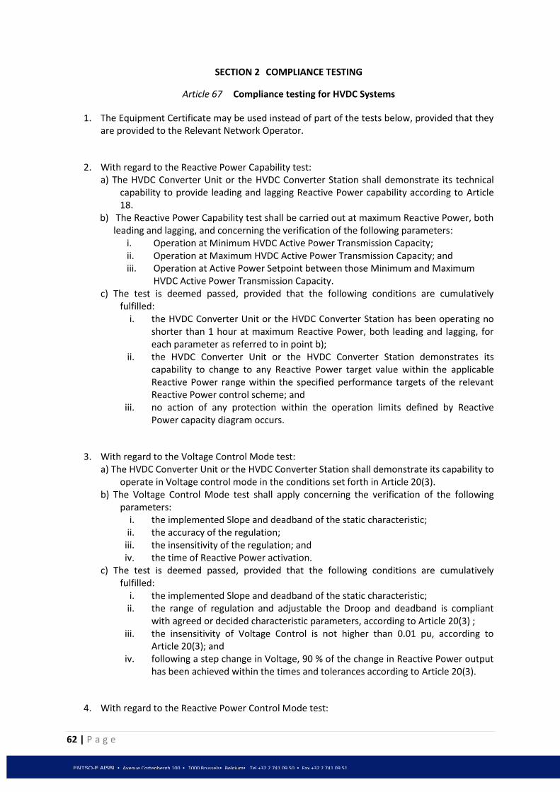
62 | P a g e
ENTSO-E AISBL • Avenue Cortenbergh 100 • 1000 Brussels• Belgium• Tel +32 2 741 09 50 • Fax +32 2 741 09 51
SECTION 2 COMPLIANCE TESTING
Article 67 Compliance testing for HVDC Systems
1. The Equipment Certificate may be used instead of part of the tests below, provided that they are provided to the Relevant Network Operator.
2. With regard to the Reactive Power Capability test: a) The HVDC Converter Unit or the HVDC Converter Station shall demonstrate its technical
capability to provide leading and lagging Reactive Power capability according to Article 18.
b) The Reactive Power Capability test shall be carried out at maximum Reactive Power, both leading and lagging, and concerning the verification of the following parameters:
i. Operation at Minimum HVDC Active Power Transmission Capacity; ii. Operation at Maximum HVDC Active Power Transmission Capacity; and iii. Operation at Active Power Setpoint between those Minimum and Maximum
HVDC Active Power Transmission Capacity. c) The test is deemed passed, provided that the following conditions are cumulatively
fulfilled: i. the HVDC Converter Unit or the HVDC Converter Station has been operating no
shorter than 1 hour at maximum Reactive Power, both leading and lagging, for each parameter as referred to in point b);
ii. the HVDC Converter Unit or the HVDC Converter Station demonstrates its capability to change to any Reactive Power target value within the applicable Reactive Power range within the specified performance targets of the relevant Reactive Power control scheme; and
iii. no action of any protection within the operation limits defined by Reactive Power capacity diagram occurs.
3. With regard to the Voltage Control Mode test: a) The HVDC Converter Unit or the HVDC Converter Station shall demonstrate its capability to
operate in Voltage control mode in the conditions set forth in Article 20(3). b) The Voltage Control Mode test shall apply concerning the verification of the following
parameters: i. the implemented Slope and deadband of the static characteristic;
ii. the accuracy of the regulation; iii. the insensitivity of the regulation; and iv. the time of Reactive Power activation.
c) The test is deemed passed, provided that the following conditions are cumulatively fulfilled:
i. the implemented Slope and deadband of the static characteristic; ii. the range of regulation and adjustable the Droop and deadband is compliant
with agreed or decided characteristic parameters, according to Article 20(3) ; iii. the insensitivity of Voltage Control is not higher than 0.01 pu, according to
Article 20(3); and iv. following a step change in Voltage, 90 % of the change in Reactive Power output
has been achieved within the times and tolerances according to Article 20(3).
4. With regard to the Reactive Power Control Mode test:

63 | P a g e
ENTSO-E AISBL • Avenue Cortenbergh 100 • 1000 Brussels• Belgium• Tel +32 2 741 09 50 • Fax +32 2 741 09 51
a) The HVDC Converter Unit or the HVDC Converter Station shall demonstrate its capability to operate in Reactive Power control mode, according to the conditions referred to in Article 20(4).
b) The Reactive Power Control Mode test shall be complementary to the Reactive Power Capability test.
c) The Reactive Power Control Mode test shall apply concerning the verification of the following parameters:
i. the Reactive Power Setpoint range and step; ii. the accuracy of the regulation; and
iii. the time of Reactive Power activation. d) The test is deemed passed, provided that the following conditions are cumulatively
fulfilled: i. the Reactive Power Setpoint range and step is ensured according to Article 20(4);
and ii. the accuracy of the regulation is compliant with the conditions as referred to in
Article 20(4).
5. With regard to the Power Factor Control Mode test: a) The HVDC Converter Unit or the HVDC Converter Station shall demonstrate its capability to
operate in Power Factor control mode according to the conditions referred to in Article 20(5)
b) The Power Factor Control Mode test shall apply concerning the verification of the following parameters:
i. the Power Factor Setpoint range; ii. the accuracy of the regulation; and
iii. the response of Reactive Power due to step change of Active Power. c) The test is deemed passed, provided that the following conditions are cumulatively
fulfilled: i. the Power Factor Setpoint range and step is ensured according to Article 20(5);
ii. the time of Reactive Power activation as result of step Active Power change does not exceed the requirement according to Article 20(5); and
iii. the accuracy of the regulation is compliant with the value, as referred to in Article 20(5).
6. With regard to the FSM response test: a) The HVDC System shall demonstrate its technical capability to continuously modulate
Active Power over the full operating range between Maximum HVDC Active Power Transmission Capacity and Minimum HVDC Active Power Transmission Capacity to contribute to Frequency Control and shall verify the steady-state parameters of regulations, such as Droop and deadband and dynamic parameters, including robustness through Frequency step change response and large, fast Frequency changes.
b) The test shall be carried out by simulating Frequency steps and ramps big enough to activate at least 10% of the full Active Power Frequency response range, taking into account the Droop settings and the deadband. Simulated Frequency deviation signals shall be injected into the controller of the HVDC Converter Unit or the HVDC Converter Station.
c) The test is deemed to be passed, provided that the following conditions are all fulfilled:

64 | P a g e
ENTSO-E AISBL • Avenue Cortenbergh 100 • 1000 Brussels• Belgium• Tel +32 2 741 09 50 • Fax +32 2 741 09 51
i. activation time of full Active Power Frequency response range as result of a step Frequency change has been no longer than required by Article 11(1) (c);
ii. undamped oscillations do not occur after the step change response; iii. the initial delay time has been according to Article 11(1) (c); iv. the Droop settings are available within the range defined in Article 11(1) (c) and
deadband (thresholds) is not more than the value in Article 11(1) (c); and v. insensitivity of Active Power Frequency response at any relevant operating point
does not exceed the requirements set forth in Article 11(1) (c).
7. With regard to the LFSM-O response test: a) The HVDC System shall demonstrate its technical capability to continuously modulate
Active Power to contribute to Frequency Control in case of large increase of Frequency in the system and shall verify the steady-state parameters of regulations, such as Droop and deadband, and dynamic parameters, including Frequency step change response.
b) The test shall be carried out by simulating Frequency steps and ramps big enough to activate at least 10 % of the full operating range for Active Power in each direction, taking into account the Droop settings and the deadband. Simulated Frequency deviation signals shall be injected into the controller of the HVDC Converter Unit or the HVDC Converter Station.
c) The test is deemed passed, provided that the following conditions are both fulfilled: i. the test results, for both dynamic and static parameters, are in line with the
requirements as referred to in Article 12(1); and
ii. undamped oscillations do not occur after the step change response.
8. With regard to the LFSM-U response test: a) The HVDC System shall demonstrate its technical capability to continuously modulate
Active Power at operating points below Maximum HVDC Active Power Transmission Capacity to contribute to Frequency Control in case of large drop of Frequency in the system.
b) The test shall be carried out by simulating at appropriate Active Power load points with low Frequency steps and ramps big enough to activate at least 10 % of the full operating range for Active Power, taking into account the Droop settings and the deadband. Simulated Frequency deviation signals shall be injected into the controller of the HVDC Converter Unit or the HVDC Converter Station.
c) The test is deemed passed, provided that the following conditions are both fulfilled:
i. the test results, for both dynamic and static parameters, are in line with the requirements as referred to in Article 13(1); and
ii. undamped oscillations do not occur after the step change response.
9. With regard to the Active Power Controllability test: a) The HVDC System shall demonstrate its technical capability to continuously modulate
Active Power over the full operating range according to Article 9(1)a) and d). b) The test shall be carried out by sending manual and automatic instructions by the
Relevant TSO(s). c) The test is deemed passed, provided that the following conditions are cumulatively
fulfilled: i. The HVDC System has demonstrated stable operation
ii. The time of adjustment of the Active Power is shorter than the delay defined according to Article 9(1)a.

65 | P a g e
ENTSO-E AISBL • Avenue Cortenbergh 100 • 1000 Brussels• Belgium• Tel +32 2 741 09 50 • Fax +32 2 741 09 51
iii. The dynamic response of the HVDC System when receiving instructions aiming at performing exchange and sharing FCR, FRR or RR or participation in Imbalance Netting Process is compliant with the requirements for these products detailed in LFC&R code.
10. With regard to the ramping rate modification test: a) The HVDC System shall demonstrate its technical capability to adjust the ramping rate
according to Article 9(2). b) The test shall be carried out by sending instructions of ramping modifications by the
Relevant TSO(s) c) The test is deemed passed, provided that the following conditions are cumulatively
fulfilled: i. Ramping rate is adjustable
ii. The HVDC System has demonstrated stable operation during ramping periods
11. With regard to the black start test, if applicable: a) The HVDC System shall demonstrate its technical capability to energise the busbar of the
remote AC substation to which it is connected, within a time frame specified by the Relevant TSO, according to Article 35(3).
b) The test shall be carried out while the HVDC System starts from shut down. c) The test is deemed passed, provided that the following conditions are cumulatively
fulfilled: i. The HVDC System has demonstrated being able to energise the busbar of the
remote AC-substation to which it is connected ii. The HVDC System operates from a stable operating point at agreed capacity,
according to the procedure of Article 35(4).
Article 68 Compliance testing for DC-connected Power Park Modules and Remote-end HVDC
Converter Units
1. The Equipment Certificate may be used instead of part of the tests below, provided that they are provided to the Relevant Network Operator.
2. With regard to the Reactive Power capability test of DC Connected PPMs:
a) The DC-connected Power Park Module shall demonstrate its technical capability to provide leading and lagging Reactive Power capability according to Article 38(2).
b) The Reactive Power Capability test shall be carried out at maximum Reactive Power, both leading and lagging, and concerning the verification of the following parameters:
i. operation in excess of 60 % of Maximum Capacity for 30 minutes; ii. operation within the range of 30 – 50 % of Maximum Capacity for 30 minutes;
and iii. operation within the range of 10 – 20 % of Maximum Capacity for 60 minutes.
c) The test is deemed passed, provided that the following criteria are cumulatively fulfilled:
i. the DC-connected Power Park Module has been operating no shorter than requested duration at maximum Reactive Power, both leading and lagging, in each parameter as referred to in Article 68(2)b;
ii. the DC-connected Power Park Module has demonstrated its capability to change to any Reactive Power target value within the agreed or decided Reactive Power

66 | P a g e
ENTSO-E AISBL • Avenue Cortenbergh 100 • 1000 Brussels• Belgium• Tel +32 2 741 09 50 • Fax +32 2 741 09 51
range within the specified performance targets of the relevant Reactive Power control scheme; and
iii. no action of any protection within the operation limits defined by Reactive Power capacity diagram occurs.
3. With regard to the Reactive Power capability test of Remote-end HVDC Converter Units:
a) The HVDC Converter Unit or the HVDC Converter Station shall demonstrate its technical capability to provide leading and lagging Reactive Power capability according to Article 46(2).
b) The test is deemed passed, provided that the following conditions are cumulatively fulfilled:
i. the HVDC Converter Unit or the HVDC Converter Station has been operating no shorter than 1 hour at maximum Reactive Power, both leading and lagging, at:
- Minimum HVDC Active Power Transmission Capacity;
- Maximum HVDC Active Power Transmission Capacity; and
- an Active Power operating point between those maximum and minimum ranges;
ii. the HVDC Converter Unit or the HVDC Converter Station demonstrates its capability to change to any Reactive Power target value within the agreed or decided Reactive Power range within the specified performance targets of the relevant Reactive Power control scheme; and
iii. no action of any protection within the operation limits defined by Reactive Power capacity diagram occurs.
4. With regard to the Voltage Control Mode test: a) The DC-connected Power Park Module shall demonstrate its capability to operate in
Voltage control mode in the conditions set forth in Article 16(3) (d) point 2) of the [NC RfG].
b) The Voltage Control Mode test shall apply concerning the verification of the following parameters:
i. the implemented Slope and deadband of the static characteristic; ii. the accuracy of the regulation;
iii. the insensitivity of the regulation; and iv. the time of Reactive Power activation.
c) The test is deemed passed, provided that the following conditions are cumulatively
fulfilled: i. the implemented Slope and deadband of the static characteristic;
ii. the range of regulation and adjustable the Droop and deadband is compliant with agreed or decided characteristic parameters, according to Article 16(3) (d) of the [NC RfG];
iii. the insensitivity of Voltage Control is not higher than 0.01 pu, according to Article 16(3) (d) of the [NC RfG]; and
iv. following a step change in Voltage, 90 % of the change in Reactive Power output has been achieved within the times and tolerances according to Article 16(3) (d) of the [NC RfG].

67 | P a g e
ENTSO-E AISBL • Avenue Cortenbergh 100 • 1000 Brussels• Belgium• Tel +32 2 741 09 50 • Fax +32 2 741 09 51
5. With regard to the Reactive Power Control Mode test: a) The DC-connected Power Park Module shall demonstrate its capability to operate in
Reactive Power control mode, according to the conditions referred to in Article 16(3) (d) point 3) of the [NC RfG].
b) The Reactive Power Control Mode test shall be complementary to the Reactive Power Capability test.
c) The Reactive Power Control Mode test shall apply concerning the verification of the following parameters:
i. the Reactive Power Setpoint range and step; ii. the accuracy of the regulation; and
iii. the time of Reactive Power activation. d) The test is deemed passed, provided that the following conditions are cumulatively
fulfilled: i. the Reactive Power Setpoint range and step is ensured according to Article 16(3)
(d) of the [NC RfG]; and ii. the accuracy of the regulation is compliant with the conditions as referred to in
Article 16(3) (d) of the [NC RfG].
6. With regard to the Power Factor Control Mode test: a) The DC-connected Power Park Module shall demonstrate its capability to operate in
Power Factor control mode according to the conditions referred to in Article 16(3) (d) point 4) of the [NC RfG].
b) The Power Factor Control Mode test shall apply concerning the verification of the following parameters:
i. the Power Factor Setpoint range; ii. the accuracy of the regulation; and
iii. the response of Reactive Power due to step change of Active Power. c) The test is deemed passed, provided that the following conditions are cumulatively
fulfilled: i. the Power Factor Setpoint range and step is ensured according to Article 16(3)
(d) of the [NC RfG]; ii. the time of Reactive Power activation as result of step Active Power change does
not exceed the requirement according to Article 16(3) (d) of the [NC RfG]; and iii. the accuracy of the regulation is compliant with the value, as referred to in
Article 16(3) (d) of the [NC RfG].
7. With regard to the tests identified in this Section in paragraphs (3), (4) and (5) the Relevant TSO may select only two of the three control options for testing.
8. With regard to LFSM-O response of DC-Connected Power Park Module, the tests shall be carried out in accordance with Article 41 (2) of [NC RfG].
9. With regard to LFSM-U response of DC-Connected Power Park Module, the tests shall be carried out in accordance with Article 42(3) of [NC RfG].
10. With regard to active power controllability of DC-Connected Power Park Module, the tests shall be carried out in accordance with 42(2) of [NC RfG].
11. With regard to FSM response of DC-Connected Power Park Module, the tests shall be carried out in accordance with Article 42(4) of [NC RfG].

68 | P a g e
ENTSO-E AISBL • Avenue Cortenbergh 100 • 1000 Brussels• Belgium• Tel +32 2 741 09 50 • Fax +32 2 741 09 51
12. With regard to Frequency restoration control of DC-Connected Power Park Module, the tests shall be carried out in accordance with Article 42(5) of [NC RfG].
13. With regard to fast signal response of DC-Connected Power Park Module, the test is deemed passed if the DC-Connected Power Park Module can demonstrate its response within the time specified in Article 37(1)a).
14. With regard to tests for DC-Connected Power Park Modules where the AC collector system is not at nominal 50 Hz Frequency, the Relevant Network Operator, in coordination with the Relevant TSO, shall agree with the DC-Connected Power Park Module Owner the compliance tests required, while respecting the provisions of Article 4(3).
SECTION 3 COMPLIANCE SIMULATIONS
Article 69 Compliance simulations for HVDC Systems
1. The Equipment Certificate may be used instead of part of the simulations below, provided that they are provided to the Relevant Network Operator.
2. With regard to the fast acting additional reactive Current injection simulation: a) The HVDC Converter Unit Owner or the HVDC Converter Station Owner shall simulate the
capability for fast acting additional reactive Current injection in the conditions set forth in Article 17.
b) The simulation is deemed passed, provided that compliance with the requirement
according to Article 17 is demonstrated.
3. With regard to the fault-ride-through capability simulation: a) The HVDC System Owner shall simulate the capability for fault-ride-through capability in
the conditions set forth in Article 23.
b) The simulation is deemed passed, provided that compliance with the requirement according to Article 23 is demonstrated.
4. With regard to the Post Fault Power Active Recovery simulation:
a) The HVDC System Owner shall simulate the capability for post fault Active Power
recovery in the conditions set forth in Article 24.
b) The simulation is deemed passed, provided that compliance with the requirement according to Article 24 is demonstrated.
5. With regard to the Reactive Power capability simulation:
a) The HVDC Converter Unit Owner or the HVDC Converter Station Owner shall
simulate the capability for leading and lagging Reactive Power capability in the conditions referred to in Article 18(1)(b)-(d).

69 | P a g e
ENTSO-E AISBL • Avenue Cortenbergh 100 • 1000 Brussels• Belgium• Tel +32 2 741 09 50 • Fax +32 2 741 09 51
b) The simulation is deemed passed, provided that the following conditions are cumulatively fulfilled:
i. the simulation model of the HVDC Converter Unit or the HVDC Converter Station is validated against the compliance tests for Reactive Power Capability at the as referred to in Article 67; and
ii. compliance with the requirements as referred to in Article 18(3) (b)- (d) is demonstrated.
6. With regard to the Power Oscillations Damping Control simulation:
a) The HVDC System Owner shall demonstrate the performance of its control system (POD function) to damp power oscillations in the conditions set forth in Article 28.
b) The tuning shall result in improved damping of corresponding Active Power response of the HVDC control in combination with the POD function compared to the Active Power response of the HVDC control alone.
c) The simulation is deemed passed, provided that the following conditions are cumulatively fulfilled:
i. The POD function damps the existing power oscillations of the HVDC System within a Frequency range specified by the Relevant TSO. This Frequency range shall include the local mode Frequency of the HVDC System and the expected Network oscillations; and
ii. a change of Active Power transfer of the HVDC System as specified by the Relevant TSO does not lead to undamped oscillations in Active or Reactive Power of the HVDC System.
7. With regard to the simulation of Active Power modification in case of disturbance:
a) The HVDC System Owner shall simulate the capability to quickly modify Active Power according to Article 9(1)(b).
b) The simulation is deemed passed, provided that the following conditions are cumulatively fulfilled:
i. The HVDC System has demonstrated stable operation when following the pre-defined sequence of active power variation.
ii. The initial delay of the adjustment of the Active Power is shorter than the value specified in Article 9(1)(b) or reasonably justified if greater
8. With regard to the fast active power reversal simulation, as applicable:
a) The HVDC System Owner shall simulate the capability to quickly modify Active Power
according to Article 9(1)(c).
b) The simulation is deemed passed, provided that the following conditions are cumulatively fulfilled:
i. The HVDC System has demonstrated stable operation ii. The time of adjustment of the Active Power is shorter than the value specified in
Article 9(1)(c) or reasonably justified if greater

70 | P a g e
ENTSO-E AISBL • Avenue Cortenbergh 100 • 1000 Brussels• Belgium• Tel +32 2 741 09 50 • Fax +32 2 741 09 51
Article 70 Compliance simulations for DC-connected Power Park Modules and Remote-end HVDC Converter Units
1. DC-connected Power Park Modules are subject to the following compliance simulations. The Equipment Certificate may be used instead of part of the simulations below, provided that they are provided to the Relevant Network Operator.
2. With regard to the fast acting additional reactive Current injection simulation:
a) The DC-connected Power Park Module Owner shall simulate the capability for fast acting additional reactive Current injection in the conditions set forth in Article 15(2) (b) of the [NC RfG].
b) The simulation is deemed passed, provided that compliance with the requirement according to Article 15(2) (b) of the [NC RfG] is demonstrated.
3. With regard to the Post Fault Power Active Recovery simulation:
a) The DC-connected Power Park Module Owner shall simulate the capability for post fault Active Power recovery in the conditions set forth in Article 15(3) (a) of the [NC RfG].
b) The simulation is deemed passed, provided that compliance with the requirement according to Article 15(3) (a) of the [NC RfG] is demonstrated.
4. With regard to the Reactive Power capability simulation of DC connected PPMs:
a) The DC-connected Power Park Module Owner shall simulate the capability for
leading and lagging Reactive Power capability in the conditions referred to in Article 38(2).
b) The simulation is deemed passed, provided that the following conditions are cumulatively fulfilled:
i. the simulation model of the DC-connected Power Park Module is validated against the compliance tests for Reactive Power Capability at the as referred to in Article 68(2); and
ii. compliance with the requirements as referred to in Article 38(2) is demonstrated.
5. With regard to the Reactive Power capability simulation of Remote-end HVDC Converter Units:
a) The Remote-end HVDC Converter Unit Owner or the Remote-end HVDC Converter Station Owner shall simulate the capability for leading and lagging Reactive Power capability in the conditions referred to in Article 46 (2).
b) The simulation is deemed passed, provided that the following conditions are cumulatively fulfilled:
i. the simulation model of the Remote-end HVDC Converter Unit or the HVDC Converter Station is validated against the compliance tests for Reactive Power Capability at the as referred to in Article 68(3); and
ii. compliance with the requirements as referred to in Article 46(2) is demonstrated.

71 | P a g e
ENTSO-E AISBL • Avenue Cortenbergh 100 • 1000 Brussels• Belgium• Tel +32 2 741 09 50 • Fax +32 2 741 09 51
6. With regard to the power oscillations damping control simulation:
a) The Owner shall simulate the capability for power oscillations damping under the conditions as referred to in Article 16(3) (f) of the [NC RfG].
b) The simulation is deemed passed, provided that the model demonstrates compliance with the conditions of Article 16(3) (f) of the [NC RfG].
7. With regard to fault-ride-through capability simulation:
a) The model of the DC-connected Power Park Module Owner shall simulate the capability for fault-ride-through capability under the conditions as referred to in Article 11(3) (a) of the [NC RfG].
b) The simulation is deemed passed, provided that the model demonstrates compliance with the conditions of Article 11(3) (a) of the [NC RfG] respectively.

72 | P a g e
ENTSO-E AISBL • Avenue Cortenbergh 100 • 1000 Brussels• Belgium• Tel +32 2 741 09 50 • Fax +32 2 741 09 51
CHAPTER 7 DEROGATIONS
Article 71
General Provisions
1. The procedure for Derogation defined in this Chapter applies to all HVDC Systems, and DC-connected Power Park Modules, both existing and new, to which the provisions of this Network Code are applicable pursuant to Article 3.
2. The request for Derogation in Article 71(1) can only be submitted by the HVDC System
Owner for its HVDC System, HVDC Converter Station or HVDC Converter Unit, or by the DC-connected Power Park Module Owner for its DC-connected Power Park Module.
3. It shall also apply to Network Operators when applying for Derogations for classes of both existing and new HVDC Systems, as well as existing or new DC-connected Power Park Modules connected to their Network.
4. The Derogation process shall be transparent, non-discriminatory, non-biased, well documented and based in particular on the Cost Benefit Analysis performed in the conditions set forth by Article 63 and Article 64 by the Relevant TSO. A Cost Benefit Analysis does not need to be performed by the Relevant TSO if, on its reasoned request, an individual exception is granted to the Relevant TSO by the National Regulatory Authority.
5. Criteria for assessing the request for Derogation shall be set by the Relevant National Regulatory Authority taking into account the recommendation of the Relevant Network Operator and the Relevant TSO. The criteria set by the Relevant National Regulatory Authority shall be non-discriminatory, objective and be published by the Relevant National Regulatory Authority.
Article 72
Request for Derogation
1. HVDC System Owners to which the provisions of this Network Code apply may apply for Derogation. The request for Derogation may relate to one or several requirements of this Network Code.
2. DC-connected Power Park Module Owners to which the provisions of this Network Code apply may apply for Derogation. The request for Derogation may relate to one or several requirements of this Network Code.
3. The request for Derogation shall be submitted to the Relevant Network Operator. If the HVDC System is connecting Synchronous Areas or Control Areas, the request for Derogation shall be submitted to each of the Relevant TSOs of the affected Control Areas.
4. The request for Derogation, submitted by the HVDC System Owner or by the DC-connected Power Park Module Owner shall include all the information and documents which are required by the Relevant Network Operator in coordination with the Relevant TSO, including, but not limited to:

73 | P a g e
ENTSO-E AISBL • Avenue Cortenbergh 100 • 1000 Brussels• Belgium• Tel +32 2 741 09 50 • Fax +32 2 741 09 51
a) identification data of the applicant party, with reference contact person for any communications;
b) the specific plant or site to which the request is referred to; c) the provision of the Network Code for which a Derogation is requested, with the detailed
description of the requested Derogation; and d) detailed accompanying justification with all relevant documents supporting the Derogation
application. 5. A DSO or CDSO may apply for Derogation in respect of one or more requirements of this Network
Code by submitting a request to the Relevant TSO.
6. The request for Derogation, submitted by the DSO or CDSO shall include all the information and documents which are required by the Relevant TSO, including, inter alia, but not limited to:
a) identifying data of the DSO or CDSO, with reference contact person for any communications;
b) the number of HVDC Systems and DC-connected Power Park Modules affected and the total installed capacity to which the request is referred to;
c) the provision of the Network Code for which a Derogation is requested, with the detailed description of the requested Derogation;
d) detailed reasoning accompanied with all relevant documents supporting the request.
7. A TSO may apply for Derogation in respect of one or more requirements of this Network Code by submitting a request to the National Regulatory Authority.
8. The request for Derogation, submitted by the TSO shall include the following information: a) identifying data of the TSO, with reference contact person for any communications; b) the number of HVDC Systems and DC-connected Power Park Modules affected and the
total installed capacity to which the request is referred to; c) the provision of the Network Code for which a Derogation is requested, with the detailed
description of the requested Derogation; d) detailed reasoning accompanied with all relevant documents supporting the request.
Article 73 Decision on Derogation
1. Further to the request for Derogation submitted by a HVDC System Owner or DC-connected Power Park Module Owner, the Relevant Network Operator, in coordination with the Relevant TSO, shall assess the request and related documentation. If the request or the related documentation is considered to be incomplete the HVDC System Owner or DC-connected Power Park Module Owner shall submit the missing information as requested by the Relevant Network Operator. As from the day of the receipt of the complete request from the HVDC System Owner, or DC-connected Power Park Module Owner until the issuance of the decision granting or refusing the Derogation by the National Regulatory Authority according to Article 73(10), the HVDC System, HVDC Converter Station, HVDC Converter Unit or DC-connected Power Park Module to which the request is referred to are deemed as compliant.
2. No later than six months after the receipt of the complete request according to Article 73(1) the Relevant Network Operator shall submit to the National Regulatory Authority its assessment of the request, including a reasoned opinion, together with a related documentation and, where applicable, a Cost-Benefit Analysis.
74 | P a g e
ENTSO-E AISBL • Avenue Cortenbergh 100 • 1000 Brussels• Belgium• Tel +32 2 741 09 50 • Fax +32 2 741 09 51
3. The above deadline shall be shortened to three months in case a reasoned request for exemption
from Cost-Benefit Analysis is submitted by the Relevant Network Operator to the National Regulatory Authority.
4. If the Relevant Network Operator has requested an exemption from Cost-Benefit Analysis the National Regulatory Authority shall decide on granting or refusing the exemption within one month after the receipt of this request. If the request is rejected, the Relevant Network Operator shall provide a Cost-Benefit Analysis within three months following the decision of the National Regulatory Authority.
5. Further to the request for Derogation submitted by a DSO or CDSO, the Relevant TSO shall assess the request and related documentation. If the request or the related documentation is considered to be incomplete the DSO or CDSO shall submit the missing information as requested by the Relevant TSO. As from the day of the receipt of the complete request by the DSO or CDSO until the issuance of the decision granting or refusing the Derogation by the National Regulatory Authority according to Article 73(10), the HVDC Systems or DC-connected Power Park Modules to which the request is referred to are deemed as compliant.
6. No later than six months after the receipt of the complete request according to Article 73 (6) the TSO shall submit its assessment of the request, including a reasoned opinion, together with a related documentation and, where applicable, a Cost-Benefit Analysis performed by the DSO or CDSO.
The above deadline shall be shortened to three months in case a reasoned request for exemption from Cost-Benefit Analysis is submitted by the DSO or CDSO to the National Regulatory Authority.
If the DSO or CDSO has requested an exemption from Cost-Benefit Analysis the National Regulatory Authority shall decide on granting or refusing the exemption within one month after the receipt of this request. If the request is rejected, the DSO or CDSO shall provide a Cost-Benefit Analysis within three months following the decision of the National Regulatory Authority.
7. Further to the request for Derogation submitted by the TSO, the National Regulatory Authority shall assess the request and related documentation. If the request or the related documentation is considered to be incomplete the TSO shall submit the missing information as requested by the National Regulatory Authority. As from the day of the receipt of the complete request by the TSO until the issuance of the decision granting or refusing the Derogation by the National Regulatory Authority according to Article 73(10), the HVDC Systems or DC-connected Power Park Modules to which the request is referred to are deemed as compliant.
8. Together with the request according to Article 73(8) the TSO shall submit either a Cost-Benefit Analysis or a reasoned request for exemption from Cost-Benefit Analysis to the National Regulatory Authority. If the TSO has requested an exemption from Cost-Benefit Analysis the National Regulatory Authority shall decide on granting or rejecting this request within one month after the receipt of this request. When the request is rejected, the TSO shall provide a Cost-Benefit Analysis within three months following the decision of the National Regulatory Authority.
9. The National Regulatory Authority shall issue a motivated decision granting or refusing the Derogation and specifying the duration of the Derogation, including a reasoned opinion, within a further three months after receipt of the complete documentation.

75 | P a g e
ENTSO-E AISBL • Avenue Cortenbergh 100 • 1000 Brussels• Belgium• Tel +32 2 741 09 50 • Fax +32 2 741 09 51
10. The National Regulatory Authority shall communicate to the applicant, the Relevant Network Operator, the Relevant TSO and the Agency the decision granting or rejecting the Derogation.
11. The Agency shall monitor the procedures of Derogation and the National Regulatory Authority shall cooperate with the Agency in this task and shall provide the Agency with all information necessary for this purpose.
12. The Agency may issue a reasoned recommendation to the National Regulatory Authority to revoke any Derogation, which has been granted without due justification.
13. The National Regulatory Authority shall have the right to issue a motivated decision revoking the granted Derogation under the conditions and pursuant to the provisions of national law reserving the vested interests of the concerned grid users, in the cases where the prerequisites for granting the Derogation no longer exist for reasons attributable to the concerned grid users.
Article 74
Compliance of Existing HVDC Systems and Existing DC-connected Power Park Modules
1. The owner of an Existing HVDC System or Existing DC-connected Power Park Module, deemed significant in accordance with the procedure set forth in Article 63 and Article 64, which is not compliant with at least one requirement of the Network Code, shall apply for a Derogation from these requirements in accordance with Article 72, within twelve months from the date the requirement, with which it is not compliant, becomes applicable.
2. If one month before the expiry of the twelve-month period set in Article 74(1), no application for Derogation has been received, the Relevant Network Operator shall, by formal notice, require the non-compliant Existing HVDC System or Existing DC-connected Power Park Module System, to either conform with the requirement, or to apply for a Derogation.
3. If at the expiry of the twelve-month period, the owner of the non-compliant Existing HVDC System or Existing DC-connected Power Park Module System referred to in Article 74(1) has not applied for a Derogation, the Relevant Network Operator shall have the right to refuse operation of the Existing HVDC System or Existing DC-connected Power Park Module System. The decision on refusal of operation shall be motivated.
Article 75
Register of Derogations to the Network Code
1. Each National Regulatory Authority shall maintain and publish a register of all Derogations granted or rejected and shall provide to the Agency an updated and consolidated register at least every 6 months, with a copy to ENTSO-E.
2. These registers shall contain in particular:
a) the requirement(s) for which the Derogation is granted or refused; b) content of the Derogation; c) consequences of the granting of the Derogation; d) reasons for granting or refusing the Derogation; and e) whether the exemption from the performance of the cost-benefit analysis was granted.

76 | P a g e
ENTSO-E AISBL • Avenue Cortenbergh 100 • 1000 Brussels• Belgium• Tel +32 2 741 09 50 • Fax +32 2 741 09 51
CHAPTER 8 FINAL PROVISIONS
Article 76 Amendment of contracts and general terms and conditions
All relevant clauses in contracts and/or relevant clauses in general terms and conditions relating to the Network connection of New HVDC Systems or New DC-connected Power Park Modules shall be amended to achieve compliance with the requirements of this Network Code.
The relevant clauses shall be amended within three years after the entry into force of this Network Code.
This requirement for amendment shall apply regardless of whether the relevant contracts or general terms and conditions provide for such an amendment.
Article 77 HVDC System or DC-connected Power Park Modules connecting with Synchronous Area(s)
or Control Area(s) not bound by EU legislation
1. In case an HVDC System to which the requirements of this Network Code apply is connecting Synchronous Areas or Control Areas, with at least one Synchronous Area or one Control Area not falling under the scope of application of EU legislation, the Relevant TSO or, as the case may be, the HVDC System Owner shall endeavour to implement an agreement to ensure that the owners of HVDC Systems with no legal obligation to comply with this Network Code also cooperate to fulfil the requirements.
2. If an agreement according to Article 77(1) cannot be implemented, the Relevant TSO or, as the case may be, the HVDC System Owner concerned shall use all available means to comply with the requirements of this Network Code.
Article 78 Entry into force
This Network Code shall enter into force on the twentieth day following that of its publication in the Official Journal of the European Union.
With the exception of Article 3(7) and (8), which shall apply thirty months after the entry into force, all provisions of this Network Code shall apply as from the day of expiration of a three year period following its publication.
This Network Code shall be binding in its entirety and directly applicable in all Member States.