entrained air in - labourtaber.com air white paper.pdf · entrained air in centrifugal pumps ......
TRANSCRIPT


Entrained Air InCentrifugal PumpsThe problem: Centrifugal pumps in manyindustrial applications have deterioratingperformance for no apparent reason.
In the last 10 years, entrained air has risen by 400percent in industrial applications. A primary cause istoday’s increasingly closed-loop processes, which havebeen implemented for both environmental and safetyreasons. Other causes of entrained air are additives suchas dyes that have an affinity to hold air and includelong-used procedures such as dissolved-air flotation(DAF), which is used to float solids to the top of a tankfor skimming.
A general awakening about the true scope of theentrained-air problem, though, has yet to occur.
Plant managers are realizing, however, that the commonpractice of trying to fix pump performance problems byputting in a bigger impeller, pump or motor is costprohibitive. Many plants have maxed out their pumpsize and still have “hit the wall” when it comes toachieving satisfactory pump performance.
Often, the real solution involves addressing the growingproblem of entrained air.
When embarking on a pump-system design, thechallenge is always to strike a balance between desiredrobustness and overall system cost. In striking this
22
balance, system designers also must consider theexpense of downtime. Just as a chain is only as strongas its weakest link, an industrial process is only asviable as its weakest component.
When evaluating the design of pumping systems, youneed to look at life-cycle costs, pump reliability,downtime costs, the costs of running the pump, and theparts and labor invested over a 20-year period. (SeeFigure 1.)
In the most extreme industrial environments, pump-failure downtime can cause the most extreme expense.In these cases, the cost of downtime is so prohibitivethat the procurement challenge is actually simplified.The question becomes, simply: “Who makes thetoughest, longest-lasting and easiest-to-maintainpump?”
When it comes to pumps for entrained air handlingapplications, the answer to the robustness question is avery short list of capable units. At the top of that list arethe LaBour Pump Company’s heavy-duty TFA tripleVolute ASME/ANSI B73.1 models of pumps. (SeeFigure 2.)
What Is Entrained Air?
Entrained air is air that has entered a process liquid,either by design (planned entrained air is usuallyprocess-based) or by mistake (unplanned entrained airis usually physical-plant-related). Entrained airnormally is measured by volume at atmosphericpressure, not by weight. It can cause:
• Reduced capacity and head.• Reduced efficiency.• Increased vibration.• Increased noise.• Shaft breakage.• Loss of prime.• Accelerated corrosion.
The LaBour TFA triple-volutecentrifugal pump can handle upto 20 percent entrained air,where a typical centrifugalpump can only deal with airentrainment levels of 5 to 8percent.
EXPERTS KNOW THERE’S MORE TO BUYING A PUMP THAN THEINITIAL COST OF THE PUMP
Source: “Pump Life Cycle Costs: A Guide to LCC Analysis For Dumping Systems.”Hydraulic Institute, Europump and the US Department of Energy’s Office of Industrial Technologies
Why Should Organizations CareAbout Life-Cycle Cost?Many organizations only consider the initialpurchase and installation cost of a system. It isin the fundamental interest of the plant designeror manager to evaluate the LCC of differentsolutions before installing major new equipmentor carrying out a major overhaul. Thisevaluation will identify the most financiallyattractive alternative. As national and globalmarkets continue to become more competitive,organizations must continually seek costsavings that will improve the profitability oftheir operations. Plant equipment operationsare receiving particular attention as a source of cost savings, especially minimizing energyconsumption and plant downtime.
Figure 1.

33
What is the Difference BetweenEntrained Air and Cavitation?
Along with entrained air, cavitation is a top candidatefor causing pump problems. Cavitation occurs when thepump’s internal pressures are lower than the vaporpressure of the liquid which results in rapid vaporformation within the pump which collapse as the liquidis swept into the higher pressure regions of the pump.The cavitation effect may cause material damage to theimpeller and possibly casing, which is resultant of thesudden formation and implosion of vapor bubbles. Thefrequencies recorded of cavitation “hammering” arefrom 1,000 cycles per second up to 25,000 cycles persecond and the resultant damage is generally termedpitting. The noise (sand, gravel, rumbling) heard outsidethe pump during cavitation, is caused by the collapse ofthe vapor bubbles.
The energy expended in accelerating the liquid to highvelocity in filling the void left by the bubble is a loss,and causes the drop in head associated with cavitation.The loss in capacity is the result of pumping a mixtureof vapor and liquid instead of liquid. Water, forexample, at 70°F increases in volume about 54,000times when vaporized, and thus even a slight amount ofcavitation will reduce the capacity significantly.
Cavitation and entrained air are related issues. Thesame pressure differential that causes cavitation canalso exacerbate entrained-air problems. When entrainedair gets into a pump, the lower-pressure bubblesbecome larger. If an air bubble gets big enough to coverthe impeller eye, the pump becomes airbound.
A generality to keep in mind when evaluating entrainedair vs. cavitation is this:
1) If it’s entrained air, the liquid entering the pumpalready has liquid and air. In the pump it’s liquidand air. And it comes out liquid and air.
2) With most traditional cavitation, the liquid cominginto the pump is fully liquid. As soon as it hits theinlet of the pump, it starts to vaporize and comesout as liquid.
Only about 75 percent of cavitation creates pump noisebut the material damage is always there.
To truly determine whether cavitation is causing yourpump performance problems, the most certain methodis to physically inspect the impeller for damage. If it’scavitation, you’ll see the pitting damage on theimpeller.
Often, however, opening a pump for physical inspectionis very much a last resort. For these cases, here arethree rules of thumb for determining whether cavitationis causing pump performance problems:
1) Throttle the discharge and check the noise –Throttle back the pump on the discharge (not thesuction) to lower the flow rate. If the pump noisegoes away, it’s about an 80 percent probabilitythat cavitation is the problem.
Figure 2.
Example of Entrained AirApplication.

44
2) Raise the liquid level and check for noise – If youraise the liquid level in the supply tank and thepump noise goes away, it’s about an 80 percentprobability of cavitation.
3) Cool the liquid and check for noise – If theprocess liquid is normally at 200°F and you cool itto 180°F and the pump noise goes away, it’sprobably cavitation.
Entrained Air in Centrifugal Pumps
Most centrifugal pumps are not designed to operate on amixture of liquid and gases.
The problem to be addressed is the tendency for the gasto accumulate in the pump suction inhibiting flow andhead generation. If the gas is allowed to continue tocollect the pump will lose its prime.
The presence of only small quantities of air can result inconsiderable reduction in capacity. (See Figure 3.)
Entrained air can reduce pump performancedramatically:
• 2 percent entrained air can reduce pump performanceby 10 to 12 percent.
• 4 percent entrained air can reduce pump performanceby 44 percent.
If air is present, the pump is likely to operate with acertain amount of “internal noise.” This noise can bedescribed as a “gravel noise,” sound very much like thepump was handling water full of gravel. This is the
same type of noise generally associated with cavitation.Here are some “break points” for determining whichtype of pump you’ll need to handle your process liquidwith various percentages of air entrainment:
• 6 to 8 percent entrained air: A horizontal end suctionpump with a Frances-vane impeller (see the LaBourTFA, and 8175 models) is typically called for.
• 8 to 15 percent entrained air: A pump from the firstcategory is typically modified with a feeder (alsosometimes called an inducer). Disc-flow pumps andrecessed-impeller pumps also are commonly specifiedat this level of air entrainment.
• 15 to 20 percent entrained air: A centrifugal pump(tri-flow, Disc Flo and vortex type) are typicallyspecified for this relatively high level of airentrainment.
• Above 20 percent entrained air: A self-priming pumpis typically specified when entrained-air levels riseabove 20 percent.
How to Determine Your Entrained-Air
The first step in determining your process liquid’spercentage of entrained air is to assess all the potentialair sources. The two categories are: Planned andUnplanned.
1). Planned, or process, entrained air.In some processes, entrained air occurs in theprocess liquid by design. Air or gas might beinjected. Or chemicals might be mixed, resultingin air or vapor. A typical example would bedeodorant manufacturing. Many deodorantscontain aluminum chlorohydrate, which fightsbacteria. Science students learn in school thatwhen you mix aluminum and hydrochloric acid,gases are created. As deodorant manufacturers dothis on purpose, they would need a pump that canhandle the entrained gases.
2). Unplanned, or physical-plant, entrained air.The configuration of your physical plant and thephysical movement of the process liquid are oftenthe culprits when it comes to air entrainment.
• The most obvious source of unplanned entrainedair is the piping, which might have leaks or design/installation flaws. In some evaporator orvacuum systems, for instance, leaks can cause
Figure 3: Reduction in pump head and efficiency on waterwith entrained air.
55
atmospheric pressure to be sucked into theprocess liquid. This also can occur through thestuffing box area.
• Common design/installation flaws include highspots in the suction piping where air can collect,or a suction pipe’s opening being mounted toohigh in a supply tank.
• Another common unplanned source of entrainedair is the free discharge of liquid above thesurface of the supply tank at or near the pumpsuction. This can cause further entrained air toenter the pump.
• Yet another entrained-air source is vortexing,which often is caused by improper submergenceof the pump suction line, resulting in a swirlingfunnel of air from the surface being suckeddirectly into the pump’s suction pipe.
• The vortex sources of entrained air is due toimproper submergence of the pump suction. Avortex is a swirling funnel or air from thesurface that directly feeds into the suction of thepump. Turbulence and excessive agitation areother sources of entrained air into the pump.
• Outside of the submergence level, the locationof the pipe in the sump can contribute to theamount of entrained air that the pump sees.
• Suction velocities of 2-3.5ft/sec should be thelimits on the tank discharge velocity going intothe pump suction.
How to Determine Your Entrained-AirPercentages
To actually determine the percentage of entrained air inyour process liquid, the following two methods aretypically used: the Clear-Beaker Test and the EntrainedGas Tester (EGT).
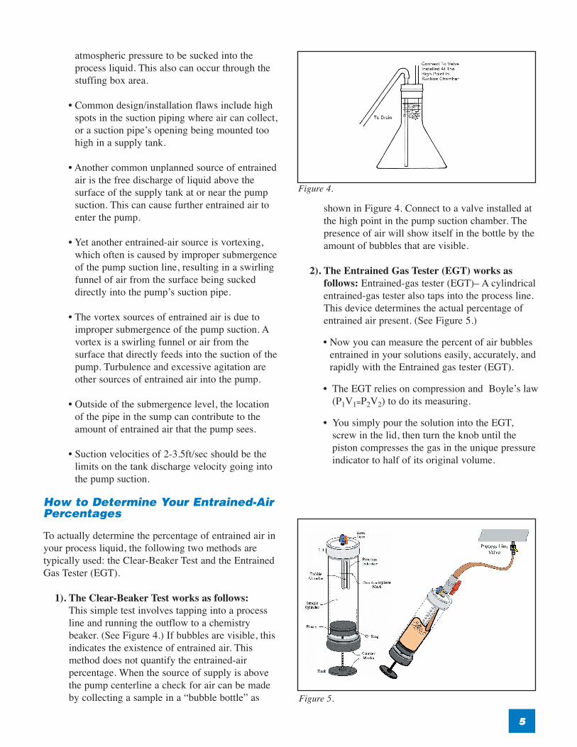
1). The Clear-Beaker Test works as follows:This simple test involves tapping into a process line and running the outflow to a chemistrybeaker. (See Figure 4.) If bubbles are visible, thisindicates the existence of entrained air. Thismethod does not quantify the entrained-airpercentage. When the source of supply is abovethe pump centerline a check for air can be madeby collecting a sample in a “bubble bottle” as
shown in Figure 4. Connect to a valve installed atthe high point in the pump suction chamber. Thepresence of air will show itself in the bottle by theamount of bubbles that are visible.
2). The Entrained Gas Tester (EGT) works asfollows: Entrained-gas tester (EGT)– A cylindricalentrained-gas tester also taps into the process line.This device determines the actual percentage ofentrained air present. (See Figure 5.)
• Now you can measure the percent of air bubblesentrained in your solutions easily, accurately, andrapidly with the Entrained gas tester (EGT).
• The EGT relies on compression and Boyle’s law(P1V1=P2V2) to do its measuring.
• You simply pour the solution into the EGT,screw in the lid, then turn the knob until thepiston compresses the gas in the unique pressureindicator to half of its original volume.
Figure 4.
Figure 5.

66
• Since the percent entrained air is proportional tothe Volume reduction, the number of revolutionsthe knob Turned, times a constant equals thepercent air. That is all there is to it.
• Depending on the lid, we can measureconsistencies from 0-5% for entrained air.
Entrained-Air Behavior in Centrifugal Pumps
A centrifugal pump’s ability to meet curve andperformance is based on having a homogeneous mixturecoming into the pump. Slugs are a problem. Entrained airis a problem. Cavitation is a problem.
In any centrifugal pump, there is a pressure drop at theinlet of the pump that causes the volume of the airbubbles to increase by the same ratio as the pressuredrop.
For instance, if the pressure drop in the suction eye of animpeller is 10 PSI, and the regular suction pressure is 20PSI, then you basically double the bubble size at thepump’s impeller.
So if your process liquid is at 5 percent entrained air,your problem will be magnified if the pump applied hasa high pressure drop in the inlet.
LaBour TFA Pump Characteristics and Applications
When they launched the revolutionary design in 1966,the inventors of the LaBour TFA had three premises forthis problem-solver pump:
1) Better viscosity handling.
2) Less shaft deflection on the impeller, bearings andmechanical seals.
3) Better handling of entrained air.
The TFA’s triple-volute (also known as tri-flow or triple-throat) configuration reduces radial loads on the shaft,resulting in deflection of the bearings and mechanicalseals that is the lowest in the industry. This balance inradial loads results in longer bearing and seal life at boththe design and low flows. This feature is particularlyimportant in aggressive services such as the pumping ofsolvents and aggressive chemicals, where an expensivemechanical seal might cost nearly as much as the pumpitself. (See Figure 6.)
The LaBour TFA pump is typically used in extremelychallenging industrial applications. Often, the TFAreplaces an ANSI-style pump that isn’t meetingperformance requirements. One reason for thisperformance differential is that most end-suction ANSI-style pumps with open impellers are limited to less than 8percent entrained air. The LaBour TFA’s star-shapedimpeller, with its extended inlet vanes and steep outletvanes, was designed to handle higher percentages ofentrained air. (See Figure 7.)
The TFA is available in a wide range of materials,including titanium and other materials that provide forextended pump life in aggressive services such as acid-slurry and reactor-fluid tanks. In addition to the highalloy materials, LaBour has an array of proprietarymetals that perform well in aggressive services. TheLaBour TFA can be supplied with nonmetallic bases withtitanium inserts that provide for extended life over thestandard fabricated-steel and other nonmetallic bases thatoften fail due to corrosion.
The LaBour TFA remains the only triple-volute pump inthe world, and its performance in extremely challengingapplications is unparalleled.
Figure 6.
Figure 7.

Conclusion: How to Find theToughest Triple Volute CentrifugalProcess Pump
The toughest industrial liquids demand the most robustprocess pumps. If you are specifying a process pump tomove liquid from a high-impact, no downtime system,the primary specification question to answer is: Whichpump is the toughest and longest lasting? When youfactor in the unacceptable cost of even the smallestamount of process downtime, the calculations leadinevitably to the toughest process pumps on the market:the better engineered, longer-lasting Triple Volute pumpfrom LaBour Pumps.
About LaBour Pumps
LaBour was founded in 1922 as a manufacturer ofcentrifugal pumps designed for handling the mostdifficult jobs with a minimum of maintenance. LaBourhas long been recognized fortheir pioneeringengineering strength. The company has many pumppatents as evidenced by the self-priming, low flow, andentrained air designs which lead the industry in thesechallenging applications.
LaBour was first with a revolutionary self-primingpump that used the “HydroBalance” principle requiringno valves, springs, floats, hoses or auxiliary pumps.This was an immediate success because of the state of
77
the art self-priming capability. Today, LaBour is theonly company to offer HydroBalance Self-PrimingPumps.
After the success of the first pump, LaBourprogressively introduced a line of horizontalcentrifugal pumps with circular casings instead of thevolute configuration (Type DZT), horizontalcentrifugal pumps that have three discharge throats(Type Q & TFA), vertical self priming centrifugals thatrequire no mechanical seals (Type G) and TypeMHL/MPL, and ANSI multiple throat pump (TypeTFA), and a very efficient line of volute horizontalcentrifugal pumps that conform to ANSI specifications(Type LVA, LVB).
Today’s global marketplace demands quiet, smooth-running, and long lasting pumps. Reliability is key andcontinued performance efficiency over the life of thepump is critical. Again and again LaBour hasdemonstrated that the superior performance andlongevity of the LaBour process pump providessubstantial savings over long term pump operation.
LaBour is a worldwide company with district officesstaffed with trained application engineers, as well asstrategically located distributors that insure prompt,efficient and reliable sales engineering service. All thisand our over 80 years of product quality, integrity, andhonesty have earned LaBour an outstanding reputationas one of the world’s leading engineered pumpmanufacturers.
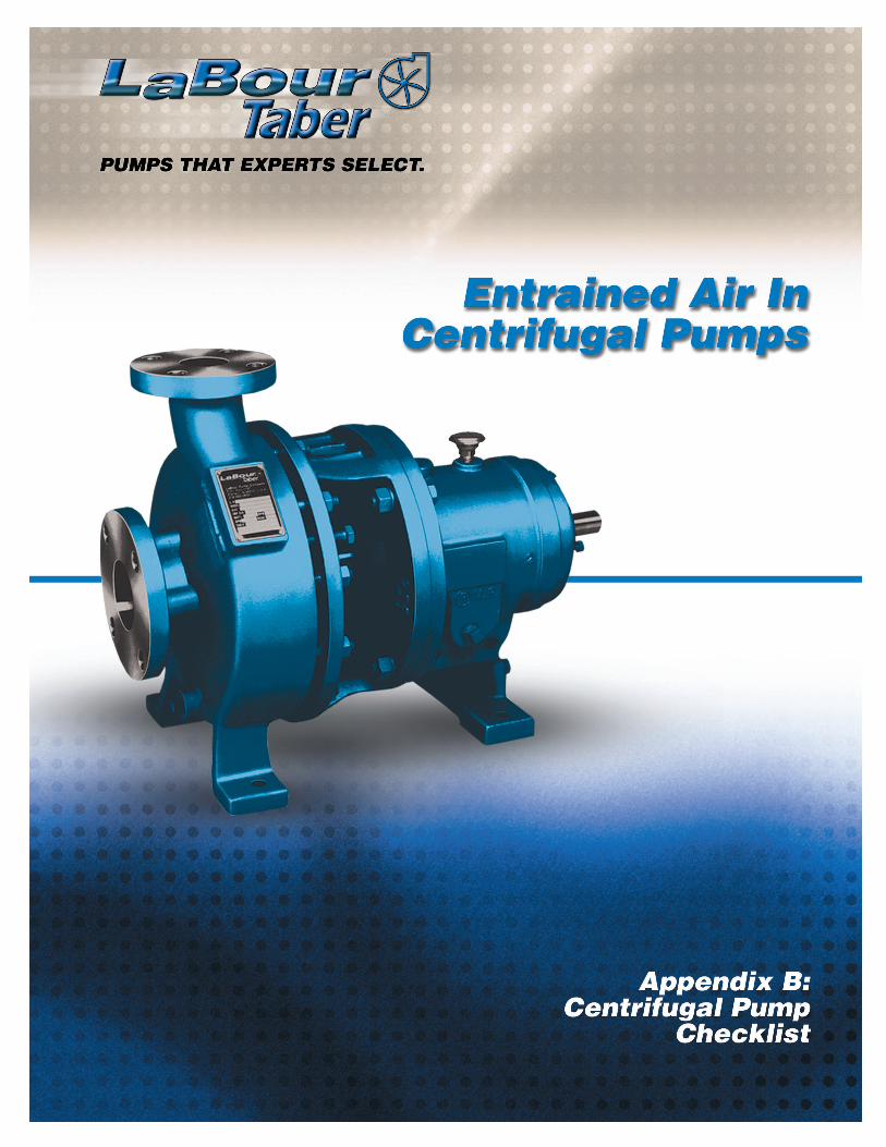
LaBour TFA Triple VoluteASME/ANSI B73.1 Pump
LaBour TFA Pump Applications
• Synthetic resins and latex• Viscous fluids• Petrochemicals• Entrained air or vapor• Solids and slurry handling• Vacuum systems• Product transfer• Industrial waste• Heat transfer• Acids
LaBour Benefits• The industry’s lowest cost of ownership over the life
cycle of the pump
• Engineered to last longer and require less maintenance
• Physically superior to competing product offerings -you can see the difference
• Designed to run cooler allowing seals and bearings tolast longer
• Worldwide technical support and quick-responseservice
• Greater lift capacity than any other brand
• Over 80 years experience in the chemical processingindustry
• The pump industry’s most impressive array ofwarranty options

88
Tools to Help You Become an Expertat Selecting a Pump
Appendix A: Feature Checklist For Your CentrifugalPump Application
The detailed feature checklist on pages 10-13 can beused to determine exact pump specifications for yourapplication. In addition to the answers to thesequestions, it’s helpful to also provide a sketch of thepump application showing the sump, or tank design,piping layouts and other installation details.
Appendix B: Centrifugal Pump Checklist
The Centrifugal Pump Checklist on pages 15-18 showsthe engineering and construction parameters of a pump.To get the most production and longest life out of yourpump, these criteria should be considered up-frontbefore ordering the pump and in addition to how thepump fits into your pumping process as outlined inAppendix A.


10101010
A Nature of the Liquid to be Pumped Comment
B Capacity Comment
C Suction Conditions Comment
What is the liquid? Fresh or salt water, acid or alkali, oil, gasoline, slurry, or paper stock, etc.?1
Is it cold or hot, what are the normal/min/max temperatures? What is the vapor pressure at the pumping temperature?2
What is its specific gravity?3
Is it viscous of nonviscous? Newtonian or non-newtonian? What is the viscosity value?4
5
What are the chemical analysis of the liquid? Ph value? Others? What are theexpected variations of the analysis? If corrosive, what has been the pastexperience, both with successful materials and with unsatisfactory materials?
6
Is it clear and free from suspended foreign matter or dirty and gritty? If the latter,what are the size and nature of the solids, and are they abrasive? If the liquid is ofa pulpy nature, what is the consistency? What is the suspended material?
What is the required capacity as well as the minimum and maximum amount ofliquid the pump will ever be called upon to deliver?1
Is there a discharge bypass line? 2
Will this pump run in parallel or series with another pump? What are thecharacteristics of these pumps?3
Is there a suction lift? Number of feet?1
Or is there suction head? Flooded min/max range in feet?2
What are the length and diameter of the suction pipe?3
What is the slope of the suction pipe?4
What valves, reducers, increasers, check valves, etc. are in the suction line?5
What is the net positive suction head available? (expressed in feet absolute).6
Is there a strainer on the suction line?7
Is there an agitator in the supply tank?8

D Discharge Conditions Comment
E Total Head Comment
F Service Conditions Comment
1111
What is the static head? Is it constant or variable?1
What is the friction head?2
What is the maximum discharge pressure against which the pump must deliverthe liquid?3
Do you have a system head curve? Is it corrected for viscosity, %solids andcondition of pipe?4
What is the minimum discharge head?5
Variations in the suction and discharge conditions will cause variations in the totalhead.1
The pump head is the total dynamic head.2
What happens when the total head increases 5%, 10% due to wear, coating, etc.?3
Is it continuous or intermittent? Please explain.1
Will the pump ever be operated against a closed discharge? Please explain.2
Will the pump be flushed and drained when not in service?3
Will the pump be used for circulation in a closed system or for transfer?4
Is there a chance that the pump may run dry?5
What will control the operation of the pump?6
How many times will the pump be required to turn on and off?7
Is there entrained air present? Turbulence in the suction feed tank?8
G Installation Comment
1212
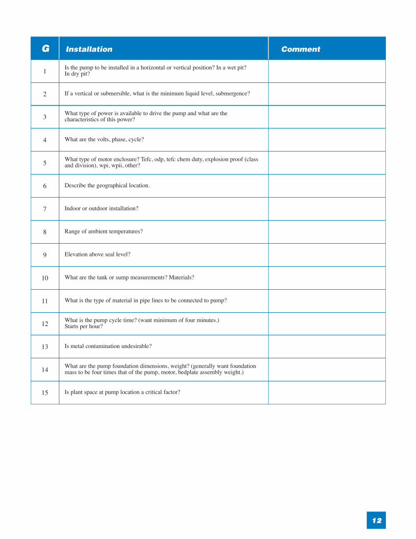
Is the pump to be installed in a horizontal or vertical position? In a wet pit? In dry pit?1
If a vertical or submersible, what is the minimum liquid level, submergence?2
What type of power is available to drive the pump and what are thecharacteristics of this power?3
What are the volts, phase, cycle?4
What type of motor enclosure? Tefc, odp, tefc chem duty, explosion proof (classand division), wpi, wpii, other?5
Describe the geographical location.6
Indoor or outdoor installation?7
Range of ambient temperatures?8
Elevation above seal level?9
What are the tank or sump measurements? Materials?10
What is the type of material in pipe lines to be connected to pump?11
What is the pump cycle time? (want minimum of four minutes.) Starts per hour?12
Is metal contamination undesirable?13
What are the pump foundation dimensions, weight? (generally want foundationmass to be four times that of the pump, motor, bedplate assembly weight.)14
Is plant space at pump location a critical factor?15

H Application Comment
I Materials Comment
J Sealing Comment
K Bedplate Comment
1313
Describe the application.1
Are there any special requirements or marked preferences with respect to thedesign, construction, or performance of the pump?2
Please provide a sketch of the installation.3
Is this a new or replacement pump?4
Are you totally satisfied with your current pump? Yes / No? Explain5
If pump is new, describe how job is done currently.6
How important is this pump to the operation of your plant?7
Previous experience. Have you pumped this liquid previously? If so, of whatmaterial or materials was the pump made of?1
What was the service life in months?2
What parts were affected?3
Was the trouble primarily due to corrosion, erosion, galvanic action, stray current?4
Was the attack uniform? If localized, what parts were involved?5
If pitted, describe size, shape and location. A sketch or picture will be helpful inan analysis of the problem.6
What is considered the intended economic life? (note: that the use of inexpensivepump materials may be the most economical, when the life and initial cost isevaluated.)
7
Do you want packing, mechanical seal, dynamic seal, magnetic drive?1
Is flush water available? What pressure?2
Do you prefer cast iron, fab steel, non-metallic, foot mounted, or feature bedplate?1
Will non-shrink grout or epoxy grout be used?2

1515
A Motor Manufacturer Comment
B Motor Comment
C Mechanical Seal Comment
D Pump Manufacturer Comment
E Pump Model/Type/Size Comment
F Bearing Housing Internal Coating Comment
1
Enclosure1
Frame/Type2
Mechanical Seal Manufacturer1
Seal Type: Single/Double/Tandem/Cartridge/Gas Type2
Seal Materials: Stationary/Rotary/Springs Materials3
Seal Gland Type: Plain/Flush/Vent & Drain/Quench4
Seal Flush Plan: ASME/ANSI or API plan number5
1
1
Internal coating of the Bearing Frame to reduce contamination1
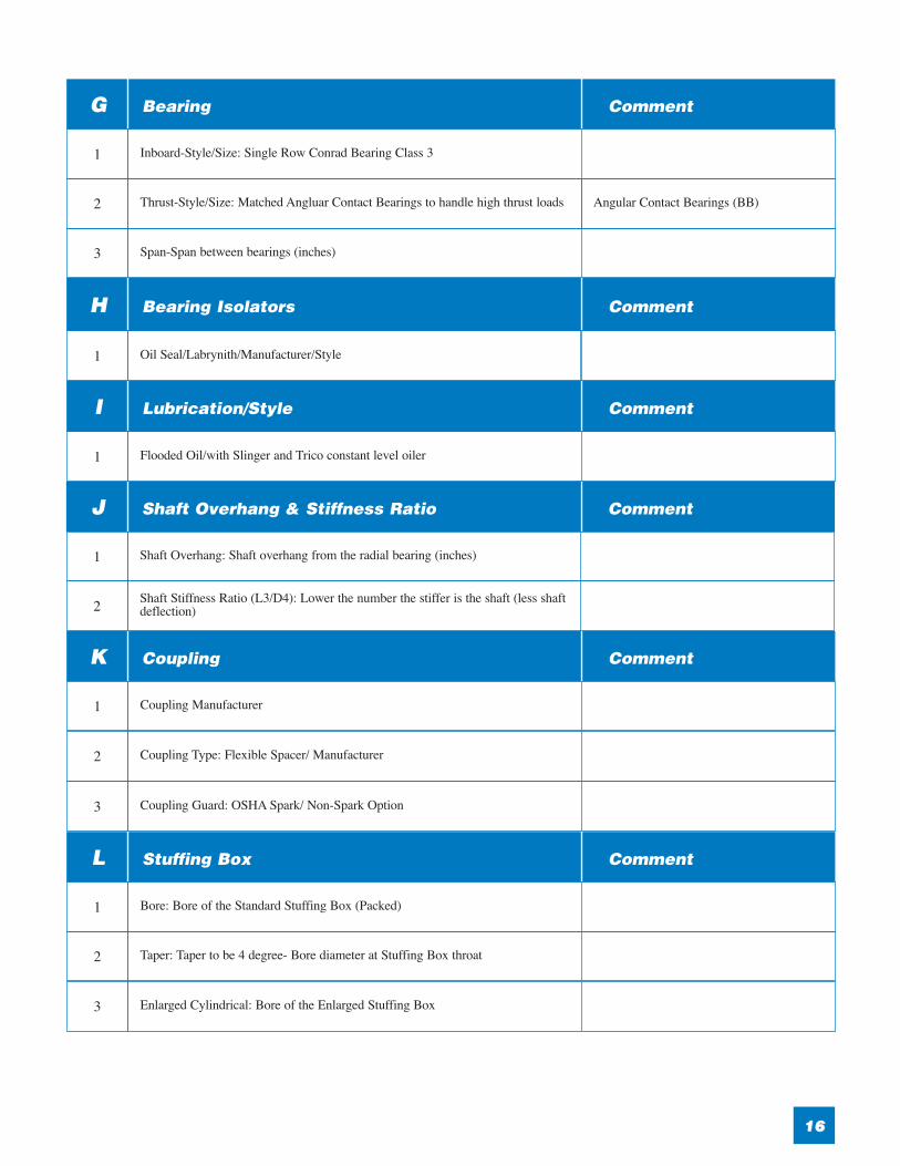
H Bearing Isolators Comment
I Lubrication/Style Comment
J Shaft Overhang & Stiffness Ratio Comment
K Coupling Comment
L Stuffing Box Comment
G Bearing Comment
1616
Oil Seal/Labrynith/Manufacturer/Style1
Flooded Oil/with Slinger and Trico constant level oiler1
Shaft Overhang: Shaft overhang from the radial bearing (inches)1
Shaft Stiffness Ratio (L3/D4): Lower the number the stiffer is the shaft (less shaftdeflection)2
Coupling Manufacturer1
Coupling Type: Flexible Spacer/ Manufacturer2
Coupling Guard: OSHA Spark/ Non-Spark Option3
Bore: Bore of the Standard Stuffing Box (Packed)1
Taper: Taper to be 4 degree- Bore diameter at Stuffing Box throat2
Enlarged Cylindrical: Bore of the Enlarged Stuffing Box3
Inboard-Style/Size: Single Row Conrad Bearing Class 3 1
Thrust-Style/Size: Matched Angluar Contact Bearings to handle high thrust loads Angular Contact Bearings (BB)2
Span-Span between bearings (inches)3

O Casing Comment
N Suction Comment
M Discharge Comment
1717
Casing to Adapter Register Rabbet Fit: Assures greater alignment of the pump assembly1
Minimum Casing Thickness2
Minimal Corrosion Allowance 0.125 inch3
Type: 150# ANSI Heavy Walled4
Type: Triple Volute Option5
Type: Gasket Material6
Drain Size (inches) 3/8" NPT7
Strainer Size/Materials8
Separator Size/Materials9
Size (inches)150#/300# ANSI F.F./R.F. Flange1
Maximum Allowable Nozzle Loads2
Size (inches)150#/300# ANSI F.F./R.F. Flange1
Maximum Allowable Nozzle Loads2
1818
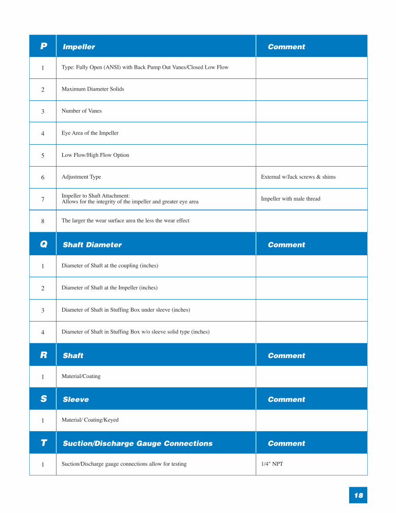
Q Shaft Diameter Comment
R Shaft Comment
S Sleeve Comment
T Suction/Discharge Gauge Connections Comment
P Impeller Comment
Diameter of Shaft at the coupling (inches)1
Diameter of Shaft at the Impeller (inches)2
Diameter of Shaft in Stuffing Box under sleeve (inches)3
Diameter of Shaft in Stuffing Box w/o sleeve solid type (inches)4
Material/Coating1
Material/ Coating/Keyed1
Suction/Discharge gauge connections allow for testing 1/4" NPT1
Type: Fully Open (ANSI) with Back Pump Out Vanes/Closed Low Flow1
Maximum Diameter Solids2
Number of Vanes3
Eye Area of the Impeller4
Low Flow/High Flow Option5
Adjustment Type External w/Jack screws & shims6
Impeller to Shaft Attachment: Allows for the integrity of the impeller and greater eye area Impeller with male thread7
The larger the wear surface area the less the wear effect8

LaBour Pumps900 Ravenwood Drive • Selma, Alabama 36701
Ph: (317) 924-7384 • Fax: (317) 920-6605www.labourtaber.com • [email protected]
Literature Number LB-022This white paper’s contents subject to change without notice.
Copyright ©2005 Peerless Pump Company