enterprise modeling and data warehousing in telecom - citeseer
TRANSCRIPT

Enterprise Modeling and Data Warehousing
in Telecom Italia
Diego Calvanese
Faculty of Computer ScienceFree University of Bolzano/Bozen
Piazza Domenicani 3I-39100 Bolzano-Bozen BZ, Italy
Luigi Dragone, Daniele Nardi, Riccardo Rosati
Dipartimento di Informatica e Sistemistica,Universita di Roma “La Sapienza”,Via Salaria 113, 00198 Roma, Italy
Stefano M. Trisolini
Telecom Italia andData Warehouse and DMDWM Consulting S.A.S. (present affiliation)
Abstract
We present a methodology for Data Warehouse design and its application within theTelecom Italia information system. The methodology is based on a conceptualrepresentation of the Enterprise, which is exploited both in the integration phaseof the Warehouse information sources and during the knowledge discovery activityon the information stored in the Warehouse. The application of the methodology inthe Telecom Italia framework has been supported by prototype software toolsboth for conceptual modeling and for data integration and reconciliation.
Key words: Data Warehousing, Data Integration, Conceptual Modeling,Automated Reasoning
Email addresses: [email protected] (Diego Calvanese),[email protected] (Luigi Dragone), [email protected] (DanieleNardi), [email protected] (Riccardo Rosati),[email protected] (Stefano M. Trisolini).
URLs: http://www.inf.unibz.it/~calvanese/ (Diego Calvanese),http://www.dis.uniroma1.it/~dragone/ (Luigi Dragone),
Accepted for publication in Information Systems July 2004

1 Introduction
Information integration (1) is one of the main problems to be addressed whendesigning a Data Warehouse (2). Possible inconsistencies and redundanciesbetween data residing at the operational data sources and migrating to theData Warehouse need to be resolved, so that the Warehouse is able to providean integrated and reconciled view of data within the organization. The basiccomponents of a data integration system are wrappers and mediators (3; 4).A wrapper is a software module that accesses a data source, extracts therelevant data, and presents such data in a specified format, typically as a setof relational tables. A mediator collects, cleans, and combines data producedby wrappers and/or other mediators, according to a specific information needof the integration system. The specification and the realization of mediatorsis the core problem in the design of an integration system.
In Data Warehouse applications, the data sources are mostly internal to theorganization. Moreover, large organizations typically provide informationalneeds in terms of an integrated conceptual representation of the corporate datathat abstracts from the physical and logical structure of data in the sources.The data stored in the Data Warehouse should reflect such an informationalneed, and hence should be defined in terms of the corporate data.
Telecom Italia is the main Italian provider of national and internationaltelecommunication services, and is among the largest companies worldwide.In large companies the need to access company data for business intelligenceis both an organizational and a technical challenge, requiring a considerableamount of financial and human resources. Given the development of informa-tion technology in the nineties, in Telecom Italia data warehousing (5) hasbeen a natural evolution of enterprise-wide data management and data inte-gration. A Data Warehouse can be defined as a set of materialized views overthe operational information sources of an organization, designed to providesupport for data analysis and management’s decisions.
In the last years, Telecom Italia has carried out a large integration ini-tiative of enterprise information systems, called IBDA 1 , resulting in the con-struction of an enterprise-wide database integrated at the conceptual level.Due to the limitations of the available technologies and the costs of replacingand re-engineering legacy applications, such an activity has lead to a solutionbased on federated databases and legacy systems wrapping, according to themain guidelines of virtual enterprise system integration.
http://www.dis.uniroma1.it/~nardi/ (Daniele Nardi),http://www.dis.uniroma1.it/~rosati/ (Riccardo Rosati).1 IBDA stands for “Integrazione di Basi di Dati Aziendali”, i.e., integration ofcompany databases.
2

Meanwhile, the information systems of Telecom Italia have quicklyevolved, in particular new applications have been developed, and existingones have been upgraded or replaced. Such a rapid evolution has been dueto both internal and external factors: the birth and growth of new markets(such as mobile telephone and Internet services) and new competitors, the pri-vatization of the company and the subsequent buyouts. Given also the variousand disparate information requirements of business intelligence and decisionmaking activities at different levels (e.g., tactical and strategical marketing),the integrated information system started showing inadequate to suit the com-pany’s new informational needs. Consequently, in order to provide an adequatetimely deployment, the development of Online Analytical Processing (OLAP)and Decision Support Systems (DSS) applications has been carried out in anunstructured way, resulting in a low modularization and non-effective usageof the Data Warehouse infrastructure.
These issues have pointed out the necessity of adopting an incrementalData Warehousing methodology, in particular, the local-as-view (LAV) ap-proach to Data Warehousing proposed in the context of the European projectDWQ 2 (6; 5). In such an approach, each table both in a source and in theData Warehouse is defined in terms of a view over the global model of the cor-porate data. This extends the traditional LAV approach to integration, wherethe information content of each data source is defined in terms of a queryover (possibly materialized) global relations constituting the corporate viewof data (7; 1; 8; 9; 10). The LAV approach is in contrast to the global-as-view(GAV) approach for data integration (11; 12; 13; 14; 15; 16; 17), typicallyproposed in Data Warehousing (2; 18). Such an approach requires, for eachinformation need, to specify the corresponding query in terms of the data atthe sources. Notably, the LAV approach enables decoupling between informa-tion availability and information requirements. Therefore, the introduction ofa new information source or the replacement of an existing one does not haveany impact on the definition of the Data Warehouse expressed over the globalmodel of corporate data.
Nonetheless, there are several important questions that are not addressed bythe work on integration. More specifically, integration anticipates semanticproblems with data, but does not address efficiency issues, which are crit-ical for data warehousing. Thus, to guarantee a proper performance of theData Warehouse, a major re-organization of the data store may be required,with additional costs. This motivates a layered architecture of the Data Ware-house (5), where a primary Data Warehouse feeds the data to several layers ofaggregation (called secondary Data Warehouses or Data Marts) before theybecome available to the final user. Moreover, typically there is the need to effi-
2 ESPRIT Basic Research Action Project EP 22469 “Foundations of Data Ware-house Quality (DWQ)”, http://www.dbnet.ece.ntua.gr/~dwq/.
3

ciently take into account legacy systems that are not integrated, and externalor extemporaneous data sources that can provide relevant information to theData Warehouse, possibly for a limited time window.
In this paper we report on the experience of Telecom Italia in the devel-opment of its Enterprise Data Warehouse. Such a Data Warehouse adopts alayered architecture, including various Primary Data Warehouses concerningphone traffic of different types and customer information, and several Sec-ondary Data Warehouses, which are at the basis of the Knowledge Discoveryand Data Mining activity carried out in Telecom Italia. For the develop-ment of its Data Warehouse Telecom Italia has followed the methodologyproposed in the DWQ project (6; 5), which is based on the LAV approach.Indeed, one of the distinguishing features of the approach is a rich model-ing language for the conceptual level that extends the Entity-Relationshipdata model, and thus is fully compatible with the conceptual modeling toolsadopted by Telecom Italia. Moreover, the modeling formalism is equippedwith automated reasoning tools, which can support the designer during DataWarehouse construction, maintenance and evolution. At the logical level, themethodology allows the designer to declaratively specify several types of Rec-onciliation Correspondences between data in different sources and in the DataWarehouse, that allow her to take care of differences in the representation atthe logical level of the same entities at the conceptual level. Such correspon-dences are then used to automatically derive the specification of the correctmediators for the loading of the materialized views of the Data Warehouse.This is done by relying on a query rewriting algorithm, whose role is to re-formulate the query that defines the view to materialize in terms of both thesource relations and the Reconciliation Correspondences. The characteristicfeature of the algorithm is that it takes into account the constraints imposedby the Conceptual Model, and uses the Reconciliation Correspondences forcleaning, integrating, and reconciling data coming from different sources.
The paper is organized as follows. In Section 2 we describe the enterprise infor-mation system in Telecom Italia. In Section 3 we introduce the enterprisemodeling framework at the basis of the Data Warehouse design methodologythat is discussed in Section 4. In Section 5 we present the development processof a portion of the Data Warehouse of Telecom Italia, concentrating on thePrimary Data Warehouse design activity. In Section 7 we briefly discuss theuse of the Secondary Data Warehouse for Data Mining and Decision Supportapplications. Finally, in Section 8 we draw some conclusions.
4

2 The Enterprise Information System in Telecom Italia
In this section we sketch the main methodological and technological issues thatarose in the last years in the development of the enterprise integrated databaseof Telecom Italia and, subsequently, in the design and implementation ofa Data Warehouse for Telecom Italia. The two efforts, although driven bydifferent needs and requirements can be regarded as a continuous developmentof an integrated view of the enterprise data. Although we analyze the designand the development of the Data Warehouses in Telecom Italia, we dealwith many issues that are common in a large enterprise; so our conclusionsare easily generalizable to other scenarios.
2.1 Data Base Integration
In 1993, Telecom Italia has launched a strategic project, called IBDA, withthe following main goals:
• the definition of an Enterprise Data Model and the migration/evolution ofexisting data;• the design and implementation of databases covering the main sections of
the Enterprise Data Model (customers, suppliers, network, administration,etc.);• the design and implementation of a client/server architecture and of the
communication middleware;• the design and implementation of data access services.
The driving motivations of the IBDA strategic project are typical of a commonscenario in many world-wide large enterprises, where there is a proliferationof legacy databases with a large overhead in the design and maintenance ofsoftware for interfacing applications and providing access to the data. IBDAwas based on a staged implementation of services that form a layer separatingdata from application processes. More specifically, the IBDA service for adatabase is the exclusive agent that provides access to the data. A databaseintegrated in the IBDA architecture is denoted as BDA and is identified bya unique number. The access is actually accomplished through contracts thatenforce the semantic and referential policies for the database.
In this case, we must cope with the numerous and extremely differentiateddata sources of the Enterprise Information System of Telecom Italia. Inparticular, one can find different applications, based on different data manage-ment technologies (from hierarchical to object-relational DBMSs), that shareinformation, or, in other words, that manage common concepts.
5

In 1996, the project was formally completed with the integration of 48 op-erational databases, while in the subsequent years new databases have beencontinuously added to IBDA. At present, several other databases are includedin IBDA as BDAs and there are ongoing projects for adding more. In thefollowing years it has been realized that the process of database inclusion inIBDA is basically incremental.
2.2 Data Warehousing
In Telecom Italia, data warehousing has been a natural evolution of dataintegration. Starting from a large integrated enterprise database, and giventhe size of the data to be stored in the Data Warehouse, the architecture ofthe Telecom Italia Enterprise Data Warehouse includes a group of PrimaryData Warehouses, which are devolved to collect, integrate and consolidate thedata extracted from the Operational Data Stores. The Primary Data Ware-houses feed the data to several systems on which the user applications (e.g.,Decision Support System) rely. These systems are also included in the Enter-prise Data Warehouse as Secondary Data Warehouses, also known as DataMarts.
The main difference between the two kinds of Data Warehouses is that the Pri-mary Data Warehouses contain only “atomic” level data, while the SecondaryData Warehouses typically contain information that has been aggregated atdifferent levels of detail. The Enterprise Data Warehouse architecture is ba-sically stratified, therefore the Secondary Data Warehouses are loaded onlywith data extracted from the Primary Data Warehouses.
Presently, the Telecom Italia Enterprise Data Warehouse includes the fol-lowing Primary Data Warehouses:
• IPDW–Interconnection Traffic Primary Data Warehouse, containing calldetail records (CDRs), whose main purpose is to analyze network usage pat-terns between Telecom Italia Network Nodes and other service providers.The daily loading is 40 millions CDRs and the store contains 6 months ofhistory data.• CPDW–Customer Primary Data Warehouse, containing information on
Telecom Italia products and services by customer, to analyze customerdata. The daily loading is about 150 GB and the average size is 1.5 TB.• TPDW–Voice Traffic Primary Data Warehouse, containing additional in-
formation on CDRs records from PSTN and ISDN switches, to supportvarious analysis tasks for Marketing, Administration, and Customer Man-agement. The daily loading is 130 millions CDRs and the store contains 12months of history data.
6

An integrated data store constitutes a solid basis for the design of Data Ware-house applications: many of the problems that arise for data warehousingare anticipated (data extraction, cleaning, and reconciliation), thus providinggood quality data for analytical processing. Moreover, Data Warehouse appli-cations can be developed in a more coherent way, because of the existence ofthe integrated data store.
Nonetheless, there are several important questions that are not addressedby the conventional approach to integration. More specifically, integrationdoes anticipate semantic problems with data, but does not address efficiencyissues, which are critical for data warehousing. Thus, to guarantee a properperformance of the Data Warehouse, a major re-organization of the data storemay be required, with additional costs.
As a consequence of the layered approach to data warehousing taken in Tele-
com Italia, a strong emphasis is given to methodologies. In the design ofthese methodologies, and their supporting tools, Telecom Italia has ben-efited from the experience on quality assurance in data warehousing gainedat the Dipartimento di Informatica e Sistemistica of the University of Rome“La Sapienza” within the European project DWQ (5). Telecom Italia hasdevised proprietary methodologies and tools for incremental schema and dataintegration based upon research results achieved within DWQ. These method-ologies provide a sound framework for data acquisition in data warehousingand for the development of Data Warehouse applications, which are based onthe cooperation with the top management, iterative refinement, and rapid pro-totyping. Such methodologies need to take into account both the complexityand the internal organization of roles and responsibilities.
3 The Enterprise Modeling Framework
In this section we describe the general framework, developed within DWQ,at the basis of our approach to schema and data integration (5; 19; 20; 21;6). Specifically, we first illustrate the architecture of a Data Warehouse inour framework. Then, we present the conceptual level of the architecture, inparticular both the formalism used for expressing the conceptual level, and themethodology for building a conceptual representation of the Data Warehouse.Finally, we describe the logical level, and the process of data integration withinour architecture.
7

Model
Sources
· · ·
· · ·
Conceptual
Data Store1
Source Source
Data Storen
Mediators
conceptual/logical mapping
physical/logical mapping
data flow
SourceSchema1
SourceScheman
Wrappers
physical levellogical level
Data WarehouseSchema Data Warehouse
Store
conceptual level
Fig. 1. Architecture for Data Integration
3.1 Architecture
A Data Warehouse can be seen as a database which maintains an inte-grated, reconciled, and materialized view of information residing in severaldata sources. In our approach, we explicitly model the data in the sources andin the Data Warehouse at different levels of abstraction (20; 6; 19):
• The conceptual level, which contains a conceptual representation of the cor-porate data.• The logical level, which contains a representation in terms of a logical data
model of the sources and of the data materialized in the Data Warehouse.• The physical level, which contains a specification of the stored data, the
wrappers for the sources, and the mediators for loading the data store.
The relationships between the conceptual and the logical, and between thelogical and the physical level, are represented explicitly by specifying map-pings between corresponding objects of the different levels. In the rest of thissection, we focus on the conceptual and logical levels, referring to the abstractarchitecture depicted in Figure 1. For a description of the physical level werefer to (5).
3.2 Conceptual Level
In the overall Data Warehouse architecture, we explicitly conceive a concep-tual level, which provides a conceptual representation of the data managedby the enterprise, including a conceptual representation of the data residingin sources, and of the global concepts and relationships that are of interestto the Data Warehouse application. Such a description, for which we use theterm Conceptual Model, is independent from any system consideration, and is
8

oriented towards the goal of expressing the semantics of the application. TheConceptual Model corresponds roughly to the notion of integrated conceptualschema in the traditional approaches to schema integration, thus providing aconsolidated view of the concepts and the relationships that are important tothe enterprise and have been currently analyzed. Such a view includes a con-ceptual representation of the portion of data, residing in the sources, currentlytaken into account. Hence, our approach is not committed to the existence ofa fully specified Conceptual Model, but rather supports an incremental defi-nition of such a model. Indeed, the Conceptual Model is subject to changesand additions as the analysis of the information sources proceeds.
An important aspect of the conceptual representation is the explicit specifica-tion of the set of interdependencies between objects in the sources and objectsin the Data Warehouse. In this respect, data integration can be regarded asthe process of understanding and representing the relationships between dataresiding in the information sources and the information contained in the DataWarehouse. Both schema integration and data integration are driven by theConceptual Model. Furthermore, data reconciliation is also addressed at theconceptual level. In fact, the specification of interdependencies can be prof-itably exploited by automated reasoning tools, which are able to derive andverify several kinds of properties concerning the conceptual specification ofinformation.
The formalization of information in the Conceptual Model is based on the dis-tinction between conceptual objects and values. Reflecting such a distinction,the Conceptual Model consists of two components:
(1) an enriched Entity-Relationship model, which formalizes the properties ofconceptual objects;
(2) a set of domain assertions, which model the properties of values (see theAppendix).
The enriched Entity-Relationship model is formalized in terms of a logic-basedformalism, called DLR (20). Such a formalism allows us to characterize theEntity-Relationship (ER) model augmented with several forms of constraintsthat cannot be expressed in the standard ER model. Moreover, it providessophisticated automated reasoning capabilities, which can be exploited in ver-ifying different properties of the Conceptual Model.
A detailed description of the features of DLR is presented in the Appendix.Here, to exemplify the use of DLR, we show how to formalize in DLR asimple ER schema. A full-fledged application of the proposed methodology isshown in a case study from the telecommunication domain (22; 23).
Example 1 The schema shown in Figure 2 represents telecommunication ser-vices, partitioned into data and voice services, and a relationship modeling the
9

cost : Money
name : NameString
activation : Date
code : CodeString 1
2
Service
DataService VoiceService
EXTENDS
Fig. 2. Entity-Relationship schema for Example 1
fact that a service may extend another service. The following set of DLRassertions exactly captures the ER schema in the figure.
Service v (= 1 name) u ∀name.NameString u(= 1 code) u ∀code.CodeString u(= 1 activation) u ∀activation.Date u(= 1 cost) u ∀cost.Money
Service ≡ DataService t VoiceService
DataService v ¬VoiceService
EXTENDS v ($1 : Service) u ($2 : Service)
The first assertion specifies the existence and uniqueness of the attributes ofService and their domains. The next two assertions specify that services arepartitioned into data and voice services. The last assertion specifies the typingof the EXTENDS relationship.
3.3 Logical Level
The logical level provides a description of the logical content of each source,called the Source Schema, and the logical content of the materialized viewsconstituting the Data Warehouse, called the Data Warehouse Schema (seeFigure 1). Such schemas are intended to provide a structural description of thecontent of both the sources and the materialized views in the Data Warehouse.
A Source Schema is provided in terms of a set of relations using the rela-tional model. The link between the logical representation and the conceptualrepresentation of the source is formally defined by associating to each rela-tion a query over the Conceptual Model that describes its content. In otherwords, the logical content of a source relation is described in terms of a viewover the virtual database represented by the Conceptual Model, adopting thelocal-as-view approach (4).
To map physical structures to logical structures, we make use of suitable wrap-pers, which encapsulate the sources. Each wrapper presents the source as a set
10

of relations, hiding how the source actually stores its data, the data model itadopts, etc. In particular, we assume that all attributes in the relations are ofinterest to the Data Warehouse application (attributes that are not of interestare hidden by the wrapper). Relation attributes are thus modeled as eitherentity attributes or relationship attributes in the Conceptual Model.
The Data Warehouse Schema, which expresses the logical content of the ma-terialized views constituting the Data Warehouse, is provided in terms of aset of relations. Similarly to the case of the sources, each relation of the DataWarehouse Schema is described in terms of a query over the Conceptual Model.
3.3.1 Queries over the Conceptual Model
From a technical point of view, queries over the Conceptual Model are unionsof conjunctive queries. More precisely, a query q over the Conceptual Modelhas the form:
T (x) ← q(x, y)
where the head T (x) defines the schema of the relation in terms of a name T ,and its arity, i.e., the number of columns (number of components of x—we usex to denote a tuple of variables x1, . . . , xn, for some n), and the body q(x, y)describes the content of the relation in terms of the Conceptual Model. Thebody has the form
conj 1(x, y1) ∨ · · · ∨ conjm
(x, ym)
where each conji(x, yi) is a conjunction of atoms, and x, yi are all the variables
appearing in the conjunction. Each atom is of the form E(t), R(t), or A(t, t′),where t, t, and t′ are variables in x, yi or constants, and E, R, and A arerespectively entities, relationships, and attributes appearing in the ConceptualModel. In the following, we will also consider queries whose body may containspecial predicates that do not appear in the conceptual model.
The semantics of queries is as follows. Given a database that satisfies theConceptual Model, a query
T (x) ← conj 1(x, y1) ∨ · · · ∨ conjm
(x, ym)
of arity n is interpreted as the set of n-tuples (d1, . . . , dn), where each di isan object of the database, such that, when substituting each di for xi, theformula
∃y1.conj 1(x, y1) ∨ · · · ∨ ∃ym.conjm
(x, ym)
evaluates to true.
Suitable inference techniques allow for carrying out the following reasoningservices on queries by taking into account the constraints imposed by the
11
Conceptual Model (24):
• Query containment. Given two queries q1 and q2 (of the same arity n) overthe Conceptual Model, we say that q1 is contained in q2, if the set of tuplesdenoted by q1 is contained in the set of tuples denoted by q2, in everydatabase satisfying the Conceptual Model.• Query consistency. A query q over the Conceptual Model is consistent, if
there exists a database satisfying the Conceptual Model in which the set oftuples denoted by q is not empty.• Query disjointness. Two queries q1 and q2 (of the same arity) over the Con-
ceptual Model are disjoint, if the intersection of the set of tuples denoted byq1 and the set of tuples denoted by q2 is empty, in every database satisfyingthe Conceptual Model.
The notion of query over the Conceptual Model is a powerful tool for modelingthe logical level of the Sources and the Data Warehouse. As mentioned above,we express the relational tables constituting both the Data Warehouse Schemaand Source Schemas in terms of queries over the Conceptual Model, with thefollowing characteristics:
• Relational tables are composed of tuples of values, which are the only kindof objects at the logical level. Therefore, each variable in the head of thequery represents a value (not a conceptual object).• Each variable appearing in the body of the query either denotes a conceptual
object or a value, depending on the atoms in which it appears. Since, in eachdatabase that satisfies the Conceptual Model, conceptual objects and valuesare disjoint sets, no query can contain a variable which can be instantiatedby both a conceptual object and a value.• Each conceptual object is represented by a tuple of values at the logical
level. Thus, a mechanism is needed to express this kind of correspondencebetween a tuple of values and the conceptual object it represents. This istaken into account by the notion of adornment introduced below.
3.3.2 Source and Data Warehouse Logical Schema Description
We remind the reader that we assume that each source is encapsulated by asuitable wrapper, and this wrapper provides a logical view of the data storedin the source in terms of the relational model, i.e., in the form of a set ofrelations.
As we said before, the query associated with a source relation provides the gluebetween the conceptual and the logical representation. However, to capturein a precise way the data in the sources, more information is needed in orderto describe the actual structure of the data in the relation. This is done byassociating to the relation an adornment, whose role is to declare the domains
12

of the columns of the table, and which are the attributes of the table thatare used to identify the objects of the Conceptual Model. In other words,the adornment is used to make it explicit how the objects of the conceptualrepresentation are coded into values of the logical representation.
An adorned query is an expression of the form
T (x) ← q(x, y) | α1, . . . , αn
where α1, . . . , αn constitutes the adornment in which each αi is an annotationon variables appearing in x. In particular:
• For each X ∈ x, we have an annotation of the form
X :: V
where V is a domain expression. Such an annotation is used to specify howvalues bound to X are represented in the table at the logical level.• For each tuple of variables z ⊆ x that is used for identifying in T a con-
ceptual object Y ∈ y mentioned in q(x, y), we have an annotation of theform
Identify([z], Y )
where we have grouped the variables z into a single argument [z]. Such anannotation makes it explicit that the tuple of values z is a representation ofthe conceptual object Y .
Similarly to the case of source relations, the relations to be materialized in theData Warehouse are described as adorned queries over the Conceptual model.Note that the adorned query associated to a table in a source is the result ofa reverse engineering analysis of the source, whereas in this case the adornedquery is a high-level specification of what we want to materialize in the table ofthe Data Warehouse, and thus of the mediator for loading such a materializedview. Since we express the semantics of the Data Warehouse tables in termsof the Conceptual Model, also the relations in the Data Warehouse are seenas views of such a Conceptual Model.
3.3.3 Reconciliation Correspondences
Assume that the decision of which data to materialize has been taken, and hasresulted in the specification of a new Data Warehouse relation T expressed interms of an adorned query. One crucial task is to design the mediator for T ,i.e., the program that accesses the sources and loads the correct data into therelation T . Designing the mediator for T requires first of all to reformulatethe query associated with T in terms of the Source relations. However, such areformulation is not sufficient. The task of mediator design is complicated by
13

the possible heterogeneity between the data in the sources. We have alreadymentioned the most important ones, namely, mismatches between data refer-ring to the same real world object, errors in the data stored in the sources,inconsistencies between values representing the properties of the real worldobjects in different sources.
To cope with this problem we follow the approach based on the notion ofReconciliation Correspondence, proposed in (19). In order to anticipate pos-sible errors, mismatches, and inconsistencies between data in the sources, ourapproach allows the designer to declaratively specify the correspondences be-tween data in different schemas (either source schemas or Data Warehouseschema). Such specification is done through special assertions, called Recon-ciliation Correspondences.
Reconciliation Correspondences are defined in terms of relations, similarly tothe case of the relations describing the sources and the Data Warehouse at thelogical level. The difference with source and Data Warehouse relations is thatwe conceive Reconciliation Correspondences as non-materialized relations, inthe sense that their extension is computed by an associated program wheneverit is needed. In particular, each Reconciliation Correspondence is specified asan adorned query with an associated program that is called to compute theextension of the virtual relation. Note that we do not consider the actual codeof the program but just its input and output parameters.
We distinguish among three types of correspondences, namely Conversion,Matching, and Merging Correspondences. A detailed description of these typesof correspondences is reported in (19).
4 Methodology for Data Warehouse Design
In this section we outline the proposed methodology for Data Warehouse de-sign, which is based on the framework presented in the previous section. Fora more detailed description of the methodology, we refer to (6; 25; 19). Themethodology identifies the following situations that need to be dealt with ina systematic manner in order to build and maintain the Conceptual Model,the Source Schemas and the Data Warehouse Schema:
• A new source (or, a new portion of a source) is analyzed and added to thewhole architecture; the data integration design scenario corresponding tothis situation will be called source-centric.• A new query is formulated by a client; the design scenario corresponding to
this situation will be called query-centric.
14
Note that, although the two scenarios refer to a dynamic situation where anew piece of information or a new request is considered, one can in practiceiterate the process to design the Data Warehouse from scratch.
In the following, we describe the most important methodological aspects thatare to be considered in the source-centric scenario, which is the approachadopted in the Telecom Italia integration project.
4.1 Conceptual Modeling
Source-centric Conceptual Model integration is triggered when a new sourceor a new portion of a source is taken into account for integration into the DataWarehouse. The steps to be accomplished in this case are the following:
(1) Source Model construction. The goal of this step is to produce the SourceModel, i.e., the conceptual model of the source under analysis. Since in atypical Data Warehouse setting, sources already exist, this task may beaccomplished through a reverse engineering activity (26).
(2) Source Model integration. The goal of this step is to integrate the con-structed Source Model with the Conceptual Model. We remind the readerthat our approach to integration is mainly declarative: the most impor-tant efforts during source integration are indeed devoted to single out andto specify the assertions relating the Conceptual Model and the SourceModels, thus producing a unified conceptual representation. More pre-cisely, the step of Source Model integration is characterized by the fol-lowing activities:(a) Conflict resolution. The goal of this activity is to detect and solve
structural and semantic conflicts involving the Source Model underanalysis, to conform and align it to the Conceptual Model and makeit compatible for integration. In general, conflict resolution cannot befully automatized: human intervention by the designer is requestedby the system when conflicts have to be solved.
(b) Defining inter-model assertions. The resulting Source Model is addedto the Conceptual Model, together with suitable inter-model asser-tions relating elements of the Source Model to elements of the Con-ceptual Model (in particular, these may be elements of previouslyintegrated Source Models).
(3) Quality analysis. The resulting Conceptual Model is evaluated and itsaccordance with quality factors that are relevant at the conceptual levelis evaluated (5). The reasoning techniques associated to the formalismat the conceptual level provide essential support during this activity (6).If necessary, a restructuring of the Conceptual Model is accomplished tomatch the required criteria.
15

4.2 Logical Level and Data Integration
The methodology for the definition of the logical level of the Data Warehouseis based on the following steps:
(1) specification of Source and Data Warehouse Schemas;(2) specification of Reconciliation Correspondences;(3) specification of mediators.
The reasoning services provided at the logical level make it possible to usethe specifications of Source and Data Warehouse Schema and of Reconcilia-tion Correspondences to automatically generate the correct mediators for theloading of the Data Warehouse. This is realized by means of a query rewritingtechnique which uses query containment as its basic reasoning service.
4.2.1 Specifying Source and Data Warehouse Schema Descriptions
The first two steps of the proposed methodology correspond to defining boththe Data Warehouse Schema and each Source Schema in terms of adornedqueries. While the design of Source Schemas does not arise particular prob-lems, the design of the Data Warehouse Schema can raise many issues dueto restructuring and denormalization of the data. The choice of the data tomaterialize, and how to organize them in relations, is an important step in theconstruction of the Data Warehouse. Several aspects have to be taken into ac-count in making these choices, for example the required storage amount, thecost of loading, refreshment, and query processing, etc. A methodology foridentifying the relations to materialize that is coherent with our frameworkhas been developed (27).
We point out that the mechanism used in our framework for specifying adornedqueries is able to cope with schematic differences (28). Indeed, as illustrated in(19), our framework allows for handling various forms of schematic differences,both among the sources, and between the sources and the Conceptual Model.
4.2.2 Specifying Reconciliation Correspondences
The task of specifying suitable Reconciliation Correspondences is a responsi-bility of the designer. Once such Reconciliation Correspondences are specified,they are profitably exploited to automatically generate mediators. In the taskof specifying Reconciliation Correspondences the system can assist the de-signer in various ways.
First of all, since each Reconciliation Correspondence is declaratively speci-
16
fied as an adorned query, all reasoning tasks available for such queries can beexploited to check desirable properties of the correspondences. In particular,the system can check the consistency of queries, rejecting inconsistent onesand giving the designer useful feedback. Also, the system can automaticallydetect whether the adorned queries associated with different correspondencesare contained in each other (or are equivalent). This is an indication of redun-dancy in the specification. However, to determine whether a correspondenceis actually redundant, one has to consider also the types of the correspon-dences and the programs associated with them. E.g., a less general query,thus specifying stricter conditions for applicability, may still be useful in thecase where the associated program takes advantage of the specialization andoperates more efficiently.
In practice, the system automatically asserts several correspondences by de-fault, thus simplifying the task of the designer. We refer the reader to (19) fora detailed description of the correspondences automatically asserted by thesystem.
4.2.3 Specifying Mediators
As mentioned, our goal is to provide support for the design of the mediatorfor a Data Warehouse relation T , i.e., the program that accesses the sourcesand loads the correct data into T . In general, the design of mediators requiresa sophisticated analysis of the data, which aims at specifying, for every rela-tion in the Data Warehouse Schema, how the tuples of the relation should beconstructed from a suitable set of tuples extracted from the sources. Mediatordesign is typically performed by hand and is a costly step in the overall DataWarehouse design process. The framework presented here is also based on adetailed analysis of the data and of the information needs. However, the knowl-edge acquired by such an analysis is explicitly expressed in the description ofsource and Data Warehouse relations, and in the Reconciliation Correspon-dences. Hence, such a knowledge can be profitably exploited to support thedesign of the mediators associated to the Data Warehouse relations.
Suppose we have decided to materialize in the Data Warehouse a new relationT , and let q be the adorned query specifying the data to materialize in T . Ourtechnique requires to proceed as follows.
(1) We determine how the data in T can be obtained from the data stored inalready defined Data Warehouse relations, the data stored in source re-lations, and the data returned by the programs that perform conversion,matching, and merging associated to the Reconciliation Correspondences.This is done by computing a rewriting of q in terms of the availableadorned queries, i.e., a new query q′ contained in q whose atoms refer to
17

(i) the already available Data Warehouse relations, (ii) the source rela-tions, (iii) the available conversion, matching, and merging predicates.
(2) We specify how to deal with tuples computed by the rewriting and pos-sibly representing the same information. Typically, we have to combinetuples coming from different sources to obtain the tuples to store in theData Warehouse relations.
(3) We refine the rewriting returned by the algorithm. E.g., certain conjunctscan be eliminated from the union of conjunctive queries according tosuitable criteria for populating Data Warehouse relations. In particular,such criteria may be determined by factors that affect the quality ofthe data in the source relations and in the Data Warehouse, such ascompleteness, accuracy, confidence, freshness, etc.
The resulting query, which will be a disjunction of conjunctive queries, is thespecification for the design of the mediator associated to T . The above stepsare discussed in more detail in (19).
5 Enterprise Modeling in Telecom Italia
In this section, we describe the development process of the Data Warehousesof Telecom Italia. Specifically, we deal with a portion of the CustomerPrimary Data Warehouse, and we specifically focus on the modeling of thedimension Contract . In the development we have carried out the followingsteps:
(1) building of the Conceptual Model by integrating the conceptual datamodels of the sources (cf. Section 4.1);
(2) definition of the contents of the Data Warehouse by specifying adornedqueries expressed in terms of the Conceptual Model built in the previousstep (cf. Section 4.2).
With regard to the first step of the methodology, as outlined in Section 2,the integration projects that have been undertaken in Telecom Italia haveproduced significant advantages for the development of the Enterprise DataWarehouse, among them, the availability of an integrated view of the enter-prise data. While this constitutes a basis for the construction of the Concep-tual Model, we have identified several conflicts in the modeling of the sources,which required restructuring operations in addition to the definition of inter-model assertions. These conflicts are due to different representations of theconcepts in the various sources.
Our methodology presupposes the use of software tools to simplify conceptualdata modeling activities. Specifically, we realized a software tool that can
18

lay out and manage data models of the data sources and the ConceptualModel and provide reasoning services to check several properties of the models.We have used a standard design platform 3 for the design of the conceptualschema and have connected it to a reasoner module implemented on top of theDescription Logics reasoning system FaCT (29). The architecture is looselycoupled: each time a reasoning service is required by the designer, she explicitlyinvokes the corresponding functionality of FaCT.
In the rest of the section we discuss in detail the first step of our methodology,while the application of the second step is discussed in Section 6. Specifically,we describe now the process of integrating the data sources that have to feedthe data to the Data Warehouse. As mentioned, this task can be split in variousdistinct phases. We notice that, since source data models are available, we donot need to construct them and we can focus our attention on the SourceModel integration phase. Given the availability of an integrated view of theEnterprise we can build the Conceptual Model in a single step, because we candirectly use the data models of all sources that we have planned to integrate.We remind that the output of this step is the integrated Conceptual Model,which expresses the information managed by the Enterprise. This model is theinput to the data integration step.
We first describe the main data sources, then concentrate on the three mainactivities in source integration, namely (i) the design of the initial ConceptualModel, (ii) conflict resolution, and (iii) the definition of inter-model assertions.Finally, we present the tool that was used to support these activities.
5.1 Data Sources Involved in the Customer Primary Data Warehouse
The Enterprise Information System of Telecom Italia (cf. Section 2) mustcope with numerous and extremely differentiated data sources. In particular,we have different applications based on different data management technolo-gies (from hierarchical to object-relational DBMSs) that share information,or, in other words, that manage common concepts.
Due to the key role played by the customer in the Telecom Italia businessprocesses, the Customer Primary Data Warehouse involves a large number ofOperational Data Stores. These Operational Data Stores can be partitionedin two main categories:
• data sources that have already been integrated (during the IBDA project);these sources, named BDAs, have an integrated Conceptual Model and are
3 To design and manage the data models we employed Cayenne GroundWorks,which is the enterprise tool adopted in Telecom Italia.
19

targeted to a particular subject; in most cases they are shared among dif-ferent applications;• data sources that are currently not integrated, called legacy data sources,
which are managed by a single application and often lack a conceptual datamodel.
This separation has important consequences on data modeling and integrationin the Data Warehouse building process.
The most important BDA data sources are the following:
DB09–Customers, which manages basic information about customers (e.g.,name, address, type, main business activity if it applies, etc.);
DB19–Business-Units, which manages information about Telecom Italia’sbusiness organization (e.g., business units, departments, etc.);
DB10–Contracts-and-Policies, which manages information about legal con-tracts and policies signed between Telecom Italia and its customers andsuppliers;
DB28–Service-Catalogue and DB44–Product-Catalogue, which describe ser-vices offered and products sold/rent by Telecom Italia to customerswith their fees/prices, special offers, marketing campaigns, etc.;
DB29–Service-Subscriptions, which manages information about the numberand type of services subscribed and products rented by customers and theiroptions.
The most important legacy data sources are the following:
ECIS–Enterprise-Customers, which is the application managing informationabout large customers (e.g., enterprises, government organizations, etc.);
RUM–Remote-Unit-Management , which is the main telecommunications net-work management application that interfaces the network devices to theinformation system;
ACM–Advanced-Customer-Management , which is the primary CustomerCare front-end application that manages information about customer con-tacts and interactions with Telecom Italia;
BCM–Breakdown-and-Complaint-Management , which is the application thatmanages information about service breakdowns and customer complaints;
NBP–New-Billing-Procedure and IBS–Integrated-Billing-System, which arethe billing systems for the domestic and business customers, respectively.
There is a degree of overlapping of the information managed by the differ-ent systems. We have detected inconsistencies between information present inmore than one system, and a number of source conflicts. We describe nowhow we have dealt with such conflicts by adopting the design methodologydescribed in the previous section.
20

In the following examples, for the sake of brevity, we focus our attention onlyon a subset of the mentioned sources.
5.2 Conceptual Model
From the analysis of project requirements, we have come to the conclusionthat concepts relevant for the Enterprise and, consequently, for the Concep-tual Model, can be successfully modeled by the Source Models of BDAs. In-deed, almost all concepts expressed in the legacy applications are subsumedby corresponding BDA concepts. However, there are a few concepts that arepresent in legacy applications, but are not modeled in BDAs: such concepts,which are currently irrelevant to the Data Warehouse, have been ignored butthey can be integrated in future. Consequently, the Conceptual Model hasbeen essentially built by unifying Source Models of BDAs.
5.3 Source Conflict Resolution
Throughout the process of Source Model integration, we have identified a largenumber of conflicts. This is due to the fact that the different Source Modelshave been developed independently, without employing homogeneous conven-tions on how to represent certain types of information. In fact, in Telecom
Italia, as in many large enterprises, each internal unit has great autonomyin the design of its own information sub-systems, which later have to be in-tegrated in the Enterprise Data Warehouse. Moreover enterprise-wide designrules have changed over the years, thus systems developed at different timeperiods may not follow the same conventions. Since in Telecom Italia wehave two main types of data sources (BDAs and legacy applications), we havedifferent kinds of conflicts between sources.
As an example, we discuss some of the integration problems that occurredwhen integrating a legacy data source, called ECIS–Enterprise-Customers,and some BDA data sources used for the design of the Customer PrimaryData Warehouse. Specifically, we describe the conflict between the entitiesFiscal Code and VAT Code 4 . The source ECIS–Enterprise-Customers, whichmanages information on large business customers, must cope with the casein which a single customer may own more than one code (fiscal or VAT).
4 The fiscal code (‘codice fiscale’) is an identification code assigned by the ItalianMinistry of Finance to every Italian citizen or enterprise, similar to a SSN. The VATcode (‘partita IVA’) is an identification code assigned to every Italian professional,enterprise, or organization. Despite the two codes serve both a similar purpose,namely identification, a mapping between them does not exist.
21

Customer
Company
Person
Customer_Type
AgreementPayment_Agreement
Denomination
Plant_Address
Address
Billing_Address
Fiscal_Code_History
VAT_Code_History
Market_Segment
TELECOM_Staff
MunicipalityProvince
Land_Registry_
Code
Chamber_of_Commerce_Entry
EEC_VAT_Code Market_
Activity
Customer_State
Customer_Group
Customer_Group_Type
Market_Activity_Group
NACE_Activity_Code
Customer_State_per_Customer
Customer_Market_Segment
Customer_per_Customer_Type
Corporate_Body
Fig. 3. Restructured conceptual data model of DB09–Customers
Therefore, in this source, a code is represented separately from a customer, byusing a different entity. Since the two types of codes serve the same purpose asfar as the system ECIS–Enterprise-Customers is concerned, they have beenmodeled both by a unique entity. On the other hand, in DB09–Customers thetwo codes are represented by two different attributes of the entity Customer.Nevertheless, at the logical/physical level, the information about the codes isstored in two different tables; in fact, the system must maintain the historyof different codes assigned to a customer.
To solve this conflict we have promoted in DB09–Customers the attributes ofthe entity Customer in two new independent entities, named VAT Code History
and Fiscal Code History. Instead, we did not consider it necessary to split theentity of ECIS–Enterprise-Customers representing the two codes into two sep-arate entities.
5.4 Defining Inter-model Assertions
In the Conceptual Model we can distinguish between two kinds of inter-modelassertions:
• assertions between BDA data sources and the Conceptual Model;• assertions that involve legacy application data models.
Assertions of the former type are often straightforward to specify, whereas weneed to analyze in more detail the latter.
22

AppendixECIS ≡int (1)
(Ad Hoc ContractDB10 u
∀CHANGEAd Hoc ContractDB10.Standard ContractDB10) t
(Standard ContractDB10 u
∀REFERENCE TOStandard ContractDB10.Standard ContractDB10) t
(Ad Hoc ContractDB10 u
∀MODIFYAd Hoc ContractDB10.Ad Hoc ContractDB10)
Fiscal CodeECIS ≡ext Fiscal Code HistoryDB09 t VAT Code HistoryDB09 (2)
ContractECIS ≡int ContractDB10 (3)
NameECIS ≡ext DenominationDB09 (4)
SeatECIS ≡ext Plant SeatDB09 (5)
Business UnitECIS ≡ext Business UnitDB19 (6)
CustomerECIS vext CustomerDB09 (7)
Table 1Inter-model assertions for the entities of the data source ECIS–Enterprise-Customers
5.4.1 Assertions between BDA Data Sources and the Conceptual Model
These assertions involve single concepts. In general, inter-model assertionslink a so-called boundary entity to the corresponding main entity by means ofan inclusion relation. The assertions between source models and the Concep-tual Model link identical concepts, since the Conceptual Model is built fromthe BDA model; therefore we have only relations stating equivalence of twoconcepts.
5.4.2 Assertions that Involve Data Models of Legacy Applications
Concepts of legacy applications have to be put in the proper correspondencewith the related concepts in the BDA sources. This is often a difficult task.In fact, since concepts of legacy applications may represent aspects that aremodeled in the BDA sources through more than one concept, we may need toexpress complex constraints holding between different source models.
We illustrate these difficulties on some examples. Figure 4 shows the concep-tual data model of the legacy application ECIS–Enterprise-Customers, whilethe inter-model assertions that involve ECIS–Enterprise-Customers are givenin Table 1. In order to give an indication of the complexity of such a task,we note that the definition of the inter-model assertions of this legacy ap-plication has required the analysis of various hundreds candidate inter-modelassertions between a dozen of BDA data source models and the remaininglegacy applications.
23

• Assertion 1 is relative to the entity Appendix, whose instance maintains addi-tional contract information. Every contract has a mandatory first appendix,defined as Contract Appendix, that contains the amount and the paymentmethod. Other types of appendices can be inserted as a consequence of acontract change (e.g., subscription to a new service) or of ad-hoc clauses(e.g., technical support, maintenance, insurance, service level agreement).The same concept is modeled in DB10–Contracts-and-Policies in a totallydifferent way. First of all, we distinguish among three types of contracts:standard, management, and ad-hoc contracts. Then, we separate main con-tracts, which state the subject of the agreement between Telecom Italia
and the customer, from secondary contracts, which specify changes to themain contract. From this specification we can deduce that every instance ofAppendixECIS is a secondary contract (standard or ad-hoc) that specifies achange to a main contract (standard or ad-hoc, too), previously signed.• Assertion 2 is a consequence of the considerations exposed in Section 5.3.
In ECIS–Enterprise-Customers the concepts related to the fiscal and theVAT code are modeled as a single entity, while two different entities existin the model of DB09–Customers. Consequently, the entity Fiscal CodeECIS
is equivalent to the union of the entities Fiscal Code HistoryDB09 andVAT Code HistoryDB09.• The entity ContractECIS represents only contracts managed by the applica-
tion ECIS–Enterprise-Customers. However, as specified by Assertion 3, theentities ContractECIS and ContractDB10 are conceptually equivalent.• Assertion 4 is due to the fact that in ECIS–Enterprise-Customers the name
inserted in the Yellow Pages corresponds to the concept Denomination ofDB09–Customers.• Assertions 5, 6, 7 are straightforward and do not need any comment.
5.5 Support Tool
We present the tool that was used to support the conceptual modeling activ-ity and some examples that show how it can effectively help the developingprocess. Our tool relies for the reasoning task on the FaCT reasoning sys-tem (29; 30; 31), which is a prototypical knowledge representation systembased on Description Logics that uses an optimized subsumption algorithmbased on tableaux. In particular, FaCT supports the typical reasoning tasksthat can be performed on conceptual schemas expressed in DLR. Notice thatFaCT has been designed to support data modeling tasks, and so it providesconcept-oriented functions. However, in its current version it cannot be em-ployed to make inference on instances of concepts.
We have integrated the FaCT reasoner as an add-on in the enterprise datamodeling CASE tool Cayenne GroundWorks. Using the CASE tool, the
24
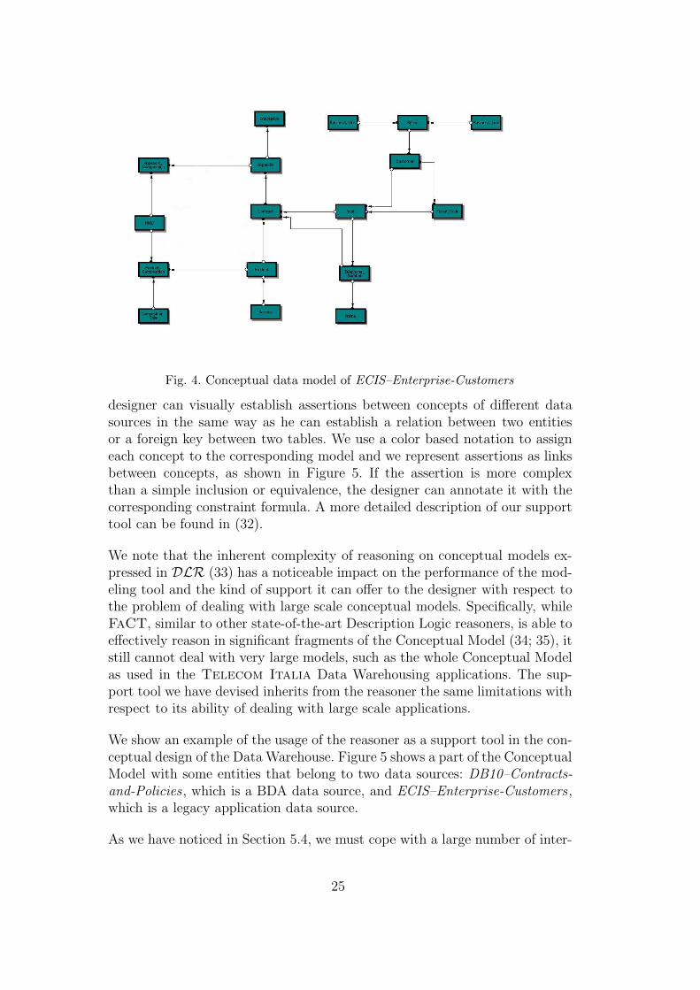
Fig. 4. Conceptual data model of ECIS–Enterprise-Customers
designer can visually establish assertions between concepts of different datasources in the same way as he can establish a relation between two entitiesor a foreign key between two tables. We use a color based notation to assigneach concept to the corresponding model and we represent assertions as linksbetween concepts, as shown in Figure 5. If the assertion is more complexthan a simple inclusion or equivalence, the designer can annotate it with thecorresponding constraint formula. A more detailed description of our supporttool can be found in (32).
We note that the inherent complexity of reasoning on conceptual models ex-pressed in DLR (33) has a noticeable impact on the performance of the mod-eling tool and the kind of support it can offer to the designer with respect tothe problem of dealing with large scale conceptual models. Specifically, whileFaCT, similar to other state-of-the-art Description Logic reasoners, is able toeffectively reason in significant fragments of the Conceptual Model (34; 35), itstill cannot deal with very large models, such as the whole Conceptual Modelas used in the Telecom Italia Data Warehousing applications. The sup-port tool we have devised inherits from the reasoner the same limitations withrespect to its ability of dealing with large scale applications.
We show an example of the usage of the reasoner as a support tool in the con-ceptual design of the Data Warehouse. Figure 5 shows a part of the ConceptualModel with some entities that belong to two data sources: DB10–Contracts-and-Policies, which is a BDA data source, and ECIS–Enterprise-Customers,which is a legacy application data source.
As we have noticed in Section 5.4, we must cope with a large number of inter-
25

Customer
Person
Company
ContractDB10
Contract
Maintenance_Contract
Maintenance_ContractDB10
Ad_Hoc_Contract
Ad_Hoc_ContractDB10
Standard_Contract
Standard_ContractDB10
ContractDB10
ContractSIAMAContractBCIS
AppendixSIAMA
AddressBCISCustomerBCIS
Plant_Address
Fig. 5. Part of the Conceptual Model involved in the example with inter-modelassertions
CustomerECIS vext Customer (8)
SeatECIS vext Plant Seat (9)
AppendixECIS vext (10)
(Ad Hoc Contract u
∀CHANGEAd Hoc Contract.Standard Contract) t
(Standard Contract u
∀REFERENCE TOStandard Contract.Standard Contract) t
(Ad Hoc Contract u
∀MODIFYAd Hoc Contract.Ad Hoc Contract)
ContractECIS vext Contract (11)
ContractDB10 vext Contract (12)
Standard ContractDB10 vext Standard Contract (13)
Ad Hoc ContractDB10 vext Ad Hoc Contract (14)
Maintenance ContractDB10 vext Maintenance Contract (15)
ContractECIS ≡int ContractDB10 (16)
Table 2Inter-model assertions involved in the example
model assertions of various kinds. We report part of these assertions in Table 2.Through these assertions we can define the relations between the ConceptualModel and their sources, as discussed below:
• Assertions 8, 9, 11, 12, 13, 14 and 15 are simple inclusion relations betweenConceptual Model entities and the corresponding source counterparts.• Assertion 10 specifies that an instance of the entity AppendixECIS can be:· a Standard Contract that modifies a Standard Contract,· an Ad Hoc Contract that modifies an Ad Hoc Contract, or· an Ad Hoc Contract that modifies a Standard Contract.
26

• Assertion 16, stating the conceptual equivalence between two entities in twosources, was already discussed.
We can make very interesting observations on this part of the ConceptualModel. Specifically, we have noticed the following property:
AppendixECIS vext Standard Contract t Ad Hoc Contract
In other words, the set of instances of the entity AppendixECIS is a sub-set of the union of the sets of instances of the entities Standard Contract
and Ad Hoc Contract. Moreover, being Standard Contract and Ad Hoc Contract
mutually exclusive, we cannot decide whether an instance of AppendixECIS be-longs to Standard Contract or Ad Hoc Contract. We must cope with this is-sue if we need to load into the Data Warehouse information on the entitiesStandard Contract and Ad Hoc Contract.
We have considered two solutions to this problem:
(1) restructuring the Conceptual Model by merging the entitiesStandard Contract and Ad Hoc Contract;
(2) restructuring the data source, by introducing a new attribute in the entityAppendixECIS to distinguish the instances that belong to Standard Contract
from those that belong to Ad Hoc Contract.
Obviously, the second solution is in general not acceptable, since it impactson the structure of the Data Warehouse sources.
If we replace Assertion 10 with the following one
AppendixECIS vext Standard Contract
stating that the instances of entity AppendixECIS are a subset of those of theentity Standard Contract, the reasoner cannot derive anymore the followingproperty:
AppendixECIS vext Standard ContractDB10 t Ad Hoc ContractDB10
In other words, the set of instances of the entity AppendixECIS is not nec-essarily a subset of the union of the sets of instances of the entitiesStandard ContractDB10 and Ad Hoc ContractDB10. This fact, together with thefact that AppendixECIS is a subset of Standard Contract, implies that we needthe source ECIS–Enterprise-Customers to populate the Conceptual Model.
27

6 Data Warehousing in Telecom Italia
In this section, we describe the second step of the development process of aportion of the Customer Primary Data Warehouse of Telecom Italia. Withregard to this step of the methodology, the design of the Data Warehouse hasbeen carried out by employing a CASE tool for the logical level. In particular,we employed Platinum ER-Win 5 , supported by the prototype tool DaRe,developed within the DWQ project, which keeps track of conceptual linksbetween data sources and helps to build mediator specifications by means ofa query rewriting algorithm.
After designing the logical model of the Data Warehouse, according to ourmethodology, we have described, by the means of adorned queries, the contentsof the data sources and of the Data Warehouse and we have introduced therequired Reconciliation Correspondences. In the last phase, we have derivedthe specifications of the mediators that load the Data Warehouse.
In the following, we describe in more detail how the various phases of theData Warehouse design methodology have been applied to the design of theCustomer Primary Data Warehouse. We note that the design methodologyhas been applied also for the design of the Secondary Data Warehouses usedfor the Knowledge Discovery and Data Mining activities of Telecom Italia
(cf. Section 7), although this activity is not reported here.
We illustrate the methodology for the design of the mediator that populates aData Warehouse table on the example of the dimension Contract of the Cus-tomer Primary Data Warehouse. According to such a methodology, we followthe local-as-view paradigm and use the Conceptual Model, built in the pre-vious step, to express by means of an adorned query the data that each datastore contains. We then use the query rewriting algorithm, implemented inour tool, to design mediators that can populate a data store with informationgathered from other data stores. In the case discussed below, we build themediator that characterizes the loading of a portion of the Data Warehousewith the information extracted from the operational data sources. We want toemphasize again the key role that the Conceptual Model plays in our frame-work, since it allows to decouple the internal organization of each data sourcefrom the other ones.
We first describe the structure of a portion of the Customer Primary DataWarehouse, concentrating on the dimension relative to contracts.
5 Platinum ER-Win is the standard tool adopted in Telecom Italia for suchkind of tasks.
28

ProductService Product_ChangeService_Change
Time
Customer
Product_ComponentService_Component
Contract Business_Unit
Telephone_Subscriber
Fig. 6. Logical model of the Customer Primary Data Warehouse – ViewCPDW–Customers
6.1 The Customer Primary Data Warehouse
As mentioned in Section 2, the Customer Primary Data Warehouse is one ofthe Primary Data Warehouses, and it is divided into four views, concerningthe representation of different aspects of the relation between the customerand the Enterprise:
Customers, which maintains information about customers and ser-vices/products that they have subscribed or bought.
Invoices, in which information about invoices and payments are stored.Contacts, which contains data about contacts of customers with customer-
care services and resellers network.Complaints, which keeps information about customers complaints.
All the views have some common properties:
• they are designed according to the star schema data model with highlydenormalized dimensions;• they manage atomic information without aggregation or summarization 6 .
We recall that the dimension Contract belongs to the view CPDW–Customersand its logical data model is depicted in Figure 6. The contents of this di-mension is built on information about different versions of service activation
6 We recall that in the Data Warehouse architecture of Telecom Italia, aggre-gation and summarization tasks are delegated to Secondary Data Warehouses.
29
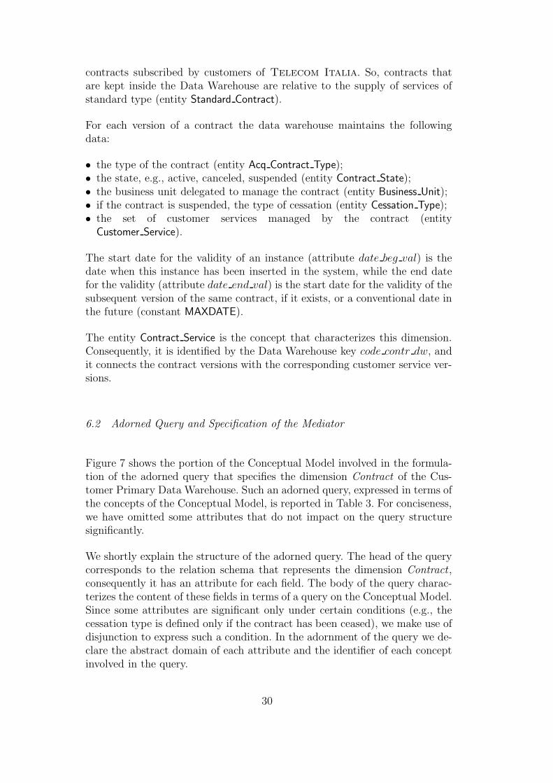
contracts subscribed by customers of Telecom Italia. So, contracts thatare kept inside the Data Warehouse are relative to the supply of services ofstandard type (entity Standard Contract).
For each version of a contract the data warehouse maintains the followingdata:
• the type of the contract (entity Acq Contract Type);• the state, e.g., active, canceled, suspended (entity Contract State);• the business unit delegated to manage the contract (entity Business Unit);• if the contract is suspended, the type of cessation (entity Cessation Type);• the set of customer services managed by the contract (entity
Customer Service).
The start date for the validity of an instance (attribute date beg val) is thedate when this instance has been inserted in the system, while the end datefor the validity (attribute date end val) is the start date for the validity of thesubsequent version of the same contract, if it exists, or a conventional date inthe future (constant MAXDATE).
The entity Contract Service is the concept that characterizes this dimension.Consequently, it is identified by the Data Warehouse key code contr dw, andit connects the contract versions with the corresponding customer service ver-sions.
6.2 Adorned Query and Specification of the Mediator
Figure 7 shows the portion of the Conceptual Model involved in the formula-tion of the adorned query that specifies the dimension Contract of the Cus-tomer Primary Data Warehouse. Such an adorned query, expressed in terms ofthe concepts of the Conceptual Model, is reported in Table 3. For conciseness,we have omitted some attributes that do not impact on the query structuresignificantly.
We shortly explain the structure of the adorned query. The head of the querycorresponds to the relation schema that represents the dimension Contract ,consequently it has an attribute for each field. The body of the query charac-terizes the content of these fields in terms of a query on the Conceptual Model.Since some attributes are significant only under certain conditions (e.g., thecessation type is defined only if the contract has been ceased), we make use ofdisjunction to express such a condition. In the adornment of the query we de-clare the abstract domain of each attribute and the identifier of each conceptinvolved in the query.
30

CONTRACTDW(
code contr dw, date beg val, date end val, code contr,
code contr ver, date year, code acq contr type, desc acq contr type,
code contr state, code state type, desc state type, code cess type,
desc cess type, code bus unit, code customer ser,
code customer ser ver
)←
Standard Contract(x),
date yy(x, date year), code contr ver(x, code contr ver),
code contr(x, code contr), date ins(x, date beg val),
Business Unit(y), ISSUED BY(x, y), code bus unit(y, code bus unit),
Acq Contract Type(z), CHARACTERIZED BY(x, z),
code acq contr type(z, code acq contr type),
desc acq contr type(z, desc acq contr type),
Contract State(w), CHARACTERIZE(w, x),
code contr state(w, code contr state),
((code cess type = NULL, desc cess type = NULL) ∨
(Cessation Type(v), IDENTIFIED BY(w, v),
code cess type(v, code cess type), desc cess type(v, desc cess type))),
State Type(u), IDENTIFIED BY(w, u),
code state type(u, code state type), desc state type(u, desc state type),
Contract Service(r), MANAGED BY(r, x),
Customer Service(s), REFERENCE TO(r, s),
code customer ser(s, code customer ser),
code customer ser ver(s, code costumer ser ver),
((Standard Contract(t), PRECEDE(x, t), date ins(t, date end val)) ∨
date end val = MAXDATE)
| code contr dw :: CODEDW, date beg val, date end val :: DATE,
date year :: NOT STANDARD DATE,
code contr ver, code contr, code bus unit, code acq contr type, code contr state,
code state type, code cess type, code customer ser,
code customer ser ver :: CODE,
desc acq contr type, desc cess type, desc state type :: DESCRIPTION,
Identify([code contr dw], r), Identify ([code contr, code contr ver, date year], x),
Identify([code acq contr type], z), Identify([code contr state], w),
Identify([code state type], u), Identify([code cess type], v),
Identify([code bus unit], y),
Identify([code customer ser, code customer ser ver], s).
Table 3Adorned query for the dimension Contract
31

Standard_Contract
Maintenance_Contract
Contract_Service
Business_Unit
Acquisition_Contract_Type
Contract_State
Customer_Service
Ad_Hoc_Contract
Contract_Cessation_
TypeState_Type
Contract
Fig. 7. Part of the Conceptual Model involved in the dimension Contract
For technical reasons, to increase performance, in the logical model of the DataWarehouse we introduce an alternative key for each dimension table, calleda data warehouse key. In this case it is the field code contr dw. We build onthis field the primary unique index of the dimension and we use this index tospeed-up joins with the fact table defining the foreign key on this field ratherthat on the natural key of the dimension. In fact, we obtain that the recordof the fact table is shorter because it contains only the values of the datawarehouse key and the index used in the join is smaller 7 .
Since the values of the data warehouse key are generated by an ad-hoc softwareprocedure, we can express it by a conversion correspondence (19) that linksthe value of the natural key, i.e., the key of the Conceptual Model model, tothe value of the data warehouse key through a program. The correspondencefor the dimension Contract is shown in Table 4. We notice that the body of theconversion correspondence is a query that describes under which conditionsthe correspondence can be employed.
We want to emphasize that the Data Warehouse stores also some information,called technical, that concerns the processes of loading and refreshing of theData Warehouse and that we cannot express in terms of the Conceptual Model.In particular, we have the following technical information:
• the field flag val, which has a boolean value and marks the instances that
7 We also define a unique index on the natural key to ensure the integrity con-straints, but it is not exploited by the query planner.
32
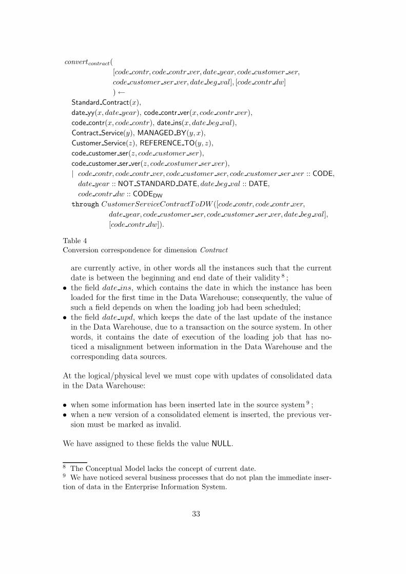
convert contract(
[code contr, code contr ver, date year, code customer ser,
code customer ser ver, date beg val], [code contr dw]
)←
Standard Contract(x),
date yy(x, date year), code contr ver(x, code contr ver),
code contr(x, code contr), date ins(x, date beg val),
Contract Service(y), MANAGED BY(y, x),
Customer Service(z), REFERENCE TO(y, z),
code customer ser(z, code customer ser),
code customer ser ver(z, code costumer ser ver),
| code contr, code contr ver, code customer ser, code customer ser ver :: CODE,
date year :: NOT STANDARD DATE, date beg val :: DATE,
code contr dw :: CODEDW
through CustomerServiceContractToDW ([code contr, code contr ver,
date year, code customer ser, code customer ser ver, date beg val],
[code contr dw]).
Table 4Conversion correspondence for dimension Contract
are currently active, in other words all the instances such that the currentdate is between the beginning and end date of their validity 8 ;• the field date ins, which contains the date in which the instance has been
loaded for the first time in the Data Warehouse; consequently, the value ofsuch a field depends on when the loading job had been scheduled;• the field date upd, which keeps the date of the last update of the instance
in the Data Warehouse, due to a transaction on the source system. In otherwords, it contains the date of execution of the loading job that has no-ticed a misalignment between information in the Data Warehouse and thecorresponding data sources.
At the logical/physical level we must cope with updates of consolidated datain the Data Warehouse:
• when some information has been inserted late in the source system 9 ;• when a new version of a consolidated element is inserted, the previous ver-
sion must be marked as invalid.
We have assigned to these fields the value NULL.
8 The Conceptual Model lacks the concept of current date.9 We have noticed several business processes that do not plan the immediate inser-tion of data in the Enterprise Information System.
33

We cannot deal successfully with this kind of data because the ConceptualModel does not have the right concepts to model update data operations.In fact, in order to express the contents of the Data Warehouse completelyand correctly we need a conceptual data model that is able to capture everytransaction on the data sources. In other words, every insert, delete, or updateoperation at the logical/physical level must correspond to an appropriate up-date operation at the conceptual level. Such kind of information can be moreadequately managed within the specification of the ETL process, in order toseparate data modeling issues from updating policies.
Since we have collected information on the data sources and on the DataWarehouse, and we have expressed it in terms of data models, adorned queries,and schema correspondences, we need to employ this knowledge to obtain thespecification of the mediators that allow us to populate the Data Warehouse.The mediator specification is carried out by our support tool, described inSection 6.3, which implements the rewriting algorithm presented in (19).
We obtain the specification of the mediator that populates the relationCONTRACTDW with data extracted from some DBA data sources. The media-tor specification is shown in Table 5 and in Table 8 we have shown, for clarity,the same specification expressed in SQL. The head of the mediator specifica-tion is the relation that the mediator is going to populate, and obviously coin-cides with the head of the adorned query that describes this relation. Instead,the body of the query is defined only in terms of relations (tables or views)of data sources that populate the Data Warehouse and Reconciliation Corre-spondences, while there is no reference to conceptual level elements. Noticethat the rewriting algorithm has correctly introduced the program specified bythe Conversion Correspondence to compute the values of the data warehousekey. We observe that we do not need to take special care when combining datacoming from different sources, since the answers to different disjuncts of thequery do not contain tuples that represent the same real world entity or thesame value.
6.3 Support Tool
Within the DWQ project a prototype tool, named DaRe, has been developedthat supports the data integration methodology described in this paper. Werefer to (36) for a detailed description of the tool. Here we briefly mention itsmain characteristics and report on its usage for the Data Warehouse designactivities in Telecom Italia.
The tool is composed of two main components:
(1) a metadata repository that allows us to manage the conceptual and logical
34

CONTRACTDW(
code contr dw, date beg val, date end val, code contr,
code contr ver, date year, code acq contr type, desc acq contr type,
code contr state, code state type, desc state type, code cess type,
desc cess type, code bus unit, code customer ser,
code customer ser ver
)←
STANDARD CONTRACTDB10(code contr dba, code contr ver,
date year, date begin val, code bus unit, code acq contr type,
code contr state, code cess type, code state type, . . . ,
code contr dba next, code contr ver next, date year next),
ACQ CONTRACT TYPEDB10(code acq contr type, desc acq contr type, . . .),
((code cess type = NULL, desc cess type = NULL) ∨
CESSATION TYPEDB10(code cess type, desc cess type, . . .)),
STATE TYPEDB10(code state type, desc state type, . . .),
((code contr dba next = NULL, code contr ver next = NULL,
date year next = NULL, date end val = MAXDATE) ∨
STANDARD CONTRACTDB10(code contr dba next, code contr ver next,
date year next, date end val, . . .)),
CONTRACT SERVICEDB29(code contr dba, code contr ver, date year,
code customer ser, code customer ser ver),
CustomerServiceContractToDW ([code contr, code contr ver,
date year, code customer ser, code customer ser ver, date beg val],
[code contr dw]).
Table 5Mediator specification for the dimension Contract
models of the data sources and of the Data Warehouse;(2) a front-end application, interfaced with the repository, that helps in the
construction of the mediators by exploiting query rewriting.
The repository is currently stored in a relational database (Oracle), nev-ertheless, the system is completely parametric with respect to the storagesystem, since its internal architecture is highly stratified. The front-end ele-ment has been developed in Java 2 and uses the Swing library to build theuser interface and the JDBC library to implement its data access objects.
The tool provides the following functionalities:
• definition of the logical models of data sources;• definition of the logical model of the Data Warehouse;• definition of the mapping between the different levels by means of adorned
queries;
35

SELECT
CustomerServiceContractToDW(X.code_contr, X.code_contr_ver,
X.date_year, X.code_customer_ser, X.code_customer_ser_ver,
X.date_beg_val) AS code_contr_dw,
X.date_beg_val,
COALESCE(W.date_beg_val, MAXDATE()) AS date_end_val,
X.code_contr,
X.code_contr_ver,
X.date_year,
X.code_acq_contr_type,
Y.desc_acq_contr_type,
X.code_contr_state,
X.code_state_type,
U.desc_state_type,
X.code_cess_type,
Z.desc_cess_type,
X.code_bus_unit,
V.code_customer_ser,
V.code_customer_ser_ver
FROM
DB10.STANDARD_CONTRACT AS X
JOIN DB10.ACQ_CONTRACT_TYPE AS Y
ON X.code_acq_contr_type = Y.code_acq_contr_type
LEFT OUTER JOIN DB10.CESSATION_TYPE AS Z
ON X.code_cess_type = Z.code_cess_type
JOIN DB10.STATE_TYPE AS U
ON X.code_state_type = U.code_state_type
LEFT OUTER JOIN DB10.STANDARD_CONTRACT AS V
ON U.code_contr_dba_next = V.code_contr_dba
AND U.code_contr_ver_next = V.code_contr
AND U.date_year_next = V.date_year
JOIN DB29.CONTRACT_SERVICE AS W
ON X.code_contr_dba = W.code_contr_dba
AND X.code_contr_ver = W.code_contr
AND X.date_year = W.date_year
Fig. 8. SQL version of the mediator specification for the dimension Contract
• definition of Reconciliation Correspondences;• automatic generation of the mediators.
For the construction of the Conceptual Model the tool relies on an externalconceptual modeling tool (i.e., Platinum ER-Win) that can interface withthe metadata repository to access and store the Conceptual Model.
We describe how this tool supports the key activities of our data integration
36

Fig. 9. DaRe tool: adorned query definition form
methodology. The working environment is subdivided in four components, onefor each key step of the methodology:
Source Schema Specification, to manage the source data models and specifyeach Source Schema in terms of the Conceptual Model;
Data Warehouse Schema Specification, to manage the Data WarehouseSchema and the corresponding adorned queries;
Reconciliation Correspondences Specification, to establish and manage theReconciliation Correspondences;
Derive Mediator, to derive the mediator specifications exploiting the queryrewriting algorithm.
The adorned query design form is shown in Figure 9.
The algorithm, implemented in the tool, that performs the automatic synthesisof the mediator through query rewriting, relies heavily on the ability to checkquery containment under the constraints imposed by the Conceptual Model.Such a task requires in general that the Description Logics reasoner is ableto reason not only on concepts but also on individual objects (24). SinceFaCT does currently not support this task, we have actually implemented anincomplete variant of the query containment test, in which objects are treatedas concepts.
37

7 Impact on Data Mining and Decision Support Applications
We now briefly describe the Decision Support System of Telecom Italia
and the Data Mining applications that we have developed on top of the DataWarehousing infrastructure. We focus our attention on the impact that ourdesign methodology has on the whole business process that involves decisionmaking activities.
The applications in the Decision Support System can be distinguished by theirusage scenarios:
• applications that support tactical decisions (e.g., customer service, directmarketing, cross selling, up selling);• applications that support strategical decisions (e.g., planning, strategical
marketing, corporate government).
Both types of applications, which are developed on Secondary Data Ware-houses according to the architecture described in Section 2, require differentdata analysis activities (e.g., OLAP, summarization, multi-dimensional anal-ysis, enterprise reporting). We have implemented an OLAP customer analy-sis application using different data management techniques (relational, multi-dimensional, hybrid). Our results are presented in (37).
We have mainly concentrated on the development of analysis applicationsbased on Data Mining techniques. In particular, we have studied differentbusiness problems, like customer segmentation, customer behavioral analy-sis, and customer survival analysis. The techniques adopted for KnowledgeDiscovery and Data Mining (KDD) and some results of their application arereported in (38; 39). We explicitly mention an investigation about the relation-ship between traditional econometric tools and KDD marketing applicationsand a combined approach for telecommunications strategic marketing (40).In the present work, we are not concerned with such applications, but withthe impact of the above described methodology in the implementation of theSecondary Data Warehouses and of the data analysis applications.
We emphasize that the availability of an integrated conceptual data model, de-signed during previous tasks, helps to substantially reduce development costsfor data analysis applications. In fact, one of the most critical aspects in thedesign of such applications is the definition and localization of informationrequired to build the model. In particular, the use of the query rewriting algo-rithm in the design of mediators allows us to express the information needs ofa data analysis application with respect to the Conceptual Model and to auto-matically obtain the queries to submit to the data sources (e.g., Primary DataWarehouses, Operational Data Stores) to retrieve the necessary information.Consequently, we can employ the methodology and the tools used to construct
38

the Primary Data Warehouses in the design of Secondary Data Warehouses.
However, since data analysis often needs summarized information, or mea-sures, we add a preliminary step to extend the Conceptual Model by intro-ducing concepts that model these aggregations. This operation is, in someways, similar to the design of multi-dimensional cubes in OLAP applications.In particular, a cube is modeled as a n-ary relationship between entities thatcorrespond to the dimensions, while the measures are modeled as attributesof the relation 10 . Therefore, an integrated conceptual data model is not onlyessential to the definition of the Enterprise Information System, but it is alsouseful to cope with the knowledge that can be extracted from it.
A key factor in a Decision Support System is the ability to represent theknowledge acquired through the analysis of data. In fact, communicability ofknowledge is essential in order to use it effectively. Our approach fully supportssuch a capability. Specifically, in the case of Data Mining applications we havethat:
(1) the datasets (training, validation, and scoring) used while building mod-els in the Knowledge Discovery process are expressed as views on theConceptual Model;
(2) the learning process (e.g., decision trees and ILP) often produces sets ofsymbolic rules expressed on the schema of the training data.
As a result, one can employ rewriting techniques to express the knowledgeextracted from the data directly with respect to the Conceptual Model. Inthis way, we can reduce the effort needed to build and maintain the knowledgeabout these rules. Additionally, since the whole Enterprise shares an integrateddata model, we can easily disseminate the data analysis results.
8 Conclusions
In this paper we have described the approach and methodologies applied inTelecom Italia for the development of Data Warehouse applications. Themethodologies have been developed within the framework of the Esprit Re-search Project DWQ and tailored to the specific needs of Telecom Italia.The experience gained can be summarized as follows.
A data integration based approach to Data Warehousing is a critical successfactor to build a quality Enterprise Data Warehouse, both in terms of quality
10 Although this information, being aggregated data, may not be directly availablein the sources, we can model these aspects using Reconciliation Correspondences.
39

of the product (applications and handled data) and in terms of quality of theprocess.
Integration and Data Warehouse construction are incremental. Integration isan incremental process both because, from the organizational point of view, itis unlikely to be able to merge all the data sources in one step, and because theData Administrator needs to incorporate new data sources that continuouslybecome available. The construction of a Data Warehouse is an incrementalprocess as well, especially in a scenario where a Data Warehouse structure in-cluding several levels of organization is adopted, as it is the case in enterprisesof the size of Telecom Italia. The incremental nature of the approach toboth Data Integration and Data Warehousing deeply influences the design ofmethodologies and tools supporting these tasks. In particular, an incrementalprocess is well supported by the local-as-view approach to Data Integration.
Data Warehousing application development is greatly enhanced by the avail-ability of an integrated Enterprise Conceptual Model, which gives to the en-terprise information assets a meaningful interpretation that is shared amongapplication developers and business specialists. The Enterprise ConceptualModel plays also a key role in the Knowledge Management process, since itenables the building of a coherent Enterprise Knowledge Base, thus promotingthe discovery, representation and dissemination of knowledge at the enterpriselevel.
The investments required for the development of methodology custom supporttools and their integration with market CASE tools and DBMSs are significant.On the other hand, the mapping translation and code generation facilitiesbased on automated reasoning enable in most cases the rapid prototyping ofData Warehouse applications. In fact, the Data Warehouse designer is ableto easily obtain a prototype that can be employed to test and validate thedesign, even involving final users of Decision Support Systems, since it ispossible to quickly build reports, decision dash boards, and pivot tables fortesting purposes. This is a noticeable advantage in the design of such kinds ofapplications, where it is very difficult to validate user requirements before alate stage of development.
A relevant issue of our framework is represented by the need to build and main-tain the Enteprise Conceptual Model and related specifications, or, in otherwords, to accurately manage the lifecycle of metadata. In a large enterpriselike Telecom Italia, it could become a serious problem, since a large num-ber of information systems are coexisting and evolving independently, andmetadata quality is strongly dependent on its freshness. Consequently, thereis the need to build and disseminate a metadata management methodology,supported by adequate tools. In our framework, the declarative specification ofconstraints and mappings may alleviate, in part, this problem. Nevertheless,
40

since the modeling and integration tasks are performed mainly at the con-ceptual level, we have experimented a higher degree of stability of the modelwith respect to technology and implementation changes, which usually havean impact on the logical/physical level. Not only, the Enterprise ConceptualModel is more stable than application models, since it depends mainly on thedomain of interest. Thus it can be adopted as a guide to change managementand migration processes (i.e., migration from a legacy application to an ERPpackage), providing a sound foundation of the data item definitions that issubstantially independent from their implementation.
An approach centered around the Enterprise Conceptual Model gives a numberof advantages in terms of building cooperative solutions during the whole ap-plication lifecycle. In fact, most software development projects are mainly con-cerned with the integration of existing solutions (i.e., exporting business logicin terms of web services). So a rich common data definition shared betweendifferent project teams, which in a large corporation like Telecom Italia
probably belong to different departments or suppliers, helps to reduce inter-facing errors and misunderstandings, improving quality and time-to-market ofapplications.
We have also experimented a positive influence on data quality assessmenttasks, which are usually performed during the Data Warehouse building pro-cess. A formal and unique data definition on all Enterprise Information Systemlevels greatly helps to identify data quality problems and their causes, and todevelop cleaning strategies. Not only, the ability of keeping track of inter-schema dependencies allows us to maintain control of data redundancy in theOperational Data Store.
References
[1] M. Lenzerini, Data integration: A theoretical perspective., in: Proc. of the21st ACM SIGACT SIGMOD SIGART Symp. on Principles of DatabaseSystems (PODS 2002), 2002, pp. 233–246.
[2] W. H. Inmon, Building the Data Warehouse, 2nd Edition, John Wiley &Sons, 1996.
[3] G. Wiederhold, Mediators in the architecture of future information sys-tems, IEEE Computer 25 (3) (1992) 38–49.
[4] J. D. Ullman, Information integration using logical views, in: Proc. ofthe 6th Int. Conf. on Database Theory (ICDT’97), Vol. 1186 of LectureNotes in Computer Science, Springer, 1997, pp. 19–40.
[5] M. Jarke, M. Lenzerini, Y. Vassiliou, P. Vassiliadis (Eds.), Fundamentalsof Data Warehouses, Springer, 1999.
[6] D. Calvanese, G. De Giacomo, M. Lenzerini, D. Nardi, R. Rosati, Infor-mation integration: Conceptual modeling and reasoning support, in: Proc.
41

of the 6th Int. Conf. on Cooperative Information Systems (CoopIS’98),1998, pp. 280–291.
[7] A. Y. Halevy, Answering queries using views: A survey, Very LargeDatabase J. 10 (4) (2001) 270–294.
[8] O. M. Duschka, M. R. Genesereth, A. Y. Levy, Recursive query plans fordata integration, J. of Logic Programming 43 (1) (2000) 49–73.
[9] F. N. Afrati, M. Gergatsoulis, T. Kavalieros, Answering queries usingmaterialized views with disjunction, in: Proc. of the 7th Int. Conf. onDatabase Theory (ICDT’99), Vol. 1540 of Lecture Notes in ComputerScience, Springer, 1999, pp. 435–452.
[10] R. Pottinger, A. Y. Levy, A scalable algorithm for answering queriesusing views, in: Proc. of the 26th Int. Conf. on Very Large Data Bases(VLDB 2000), 2000, pp. 484–495.
[11] G. Zhou, R. Hull, R. King, Generating data integration mediators thatuse materializations, J. of Intelligent Information Systems 6 (1996) 199–221.
[12] H. Garcia-Molina, Y. Papakonstantinou, D. Quass, A. Rajaraman, Y. Sa-giv, J. D. Ullman, V. Vassalos, J. Widom, The TSIMMIS approach to me-diation: Data models and languages, J. of Intelligent Information Systems8 (2) (1997) 117–132.
[13] R. Yerneni, C. Li, H. Garcia-Molina, J. D. Ullman, Computing capabili-ties of mediators, in: Proc. of the ACM SIGMOD Int. Conf. on Manage-ment of Data, 1999, pp. 443–454.
[14] C. H. Goh, S. Bressan, S. E. Madnick, M. D. Siegel, Context interchange:New features and formalisms for the intelligent integration of information,ACM Trans. on Information Systems 17 (3) (1999) 270–293.
[15] S. Bergamaschi, S. Castano, M. Vincini, D. Beneventano, Semantic inte-gration of heterogeneous information sources, Data and Knowledge En-gineering 36 (3) (2001) 215–249.
[16] D. Ursino, Extraction and Exploitation of Intensional Knowledge fromHeterogeneous Information Sources, Vol. 2282 of Lecture Notes in Com-puter Science, Springer, 2002.
[17] A. Calı, D. Calvanese, G. De Giacomo, M. Lenzerini, P. Naggar, F. Ver-nacotola, IBIS: Data integration at work, in: Proc. of the 10th Ital. Conf.on Database Systems (SEBD 2002), 2002, pp. 291–298.
[18] J. Widom, Research problems in data warehousing, in: Proc. of the 4thInt. Conf. on Information and Knowledge Management (CIKM’95), 1995.
[19] D. Calvanese, G. De Giacomo, M. Lenzerini, D. Nardi, R. Rosati, Dataintegration in data warehousing, Int. J. of Cooperative Information Sys-tems 10 (3) (2001) 237–271.
[20] D. Calvanese, G. De Giacomo, M. Lenzerini, D. Nardi, R. Rosati, De-scription logic framework for information integration, in: Proc. of the6th Int. Conf. on Principles of Knowledge Representation and Reasoning(KR’98), 1998, pp. 2–13.
[21] D. Calvanese, G. De Giacomo, M. Lenzerini, D. Nardi, R. Rosati, Source
42

integration in data warehousing, in: Proc. of the 9th Int. Workshop onDatabase and Expert Systems Applications (DEXA’98), IEEE ComputerSociety Press, 1998, pp. 192–197.
[22] S. M. Trisolini, M. Lenzerini, D. Nardi, Data integration and warehousingin Telecom Italia, in: Proc. of the ACM SIGMOD Int. Conf. on Manage-ment of Data, 1999, pp. 538–539.
[23] D. Calvanese, G. De Giacomo, M. Lenzerini, D. Nardi, R. Rosati, Use ofthe reconciliation tool at Telecom Italia, Tech. Rep. DWQ-UNIROMA-007, DWQ Consortium (Oct. 1999).
[24] D. Calvanese, G. De Giacomo, M. Lenzerini, On the decidability of querycontainment under constraints, in: Proc. of the 17th ACM SIGACT SIG-MOD SIGART Symp. on Principles of Database Systems (PODS’98),1998, pp. 149–158.
[25] D. Calvanese, G. De Giacomo, M. Lenzerini, D. Nardi, R. Rosati,Schema and data integration methodology for DWQ, Tech. Rep. DWQ-UNIROMA-004, DWQ Consortium (Sep. 1998).
[26] C. Batini, S. Ceri, S. B. Navathe, Conceptual Database Design, an Entity-Relationship Approach, Benjamin and Cummings Publ. Co., Menlo Park,California, 1992.
[27] D. Theodoratos, S. Ligoudistianos, T. Sellis, Designing the global DataWarehouse with SPJ views, in: Proc. of the 11th Int. Conf. on AdvancedInformation Systems Engineering (CAiSE’99), 1999.
[28] A. Sheth, V. Kashyap, So far (schematically) yet so near (semantically),in: Proc. of the IFIP DS-5 Conf. on Semantics of Interoperable DatabaseSystems, Elsevier Science Publishers (North-Holland), Amsterdam, 1992.
[29] I. Horrocks, Using an expressive description logic: FaCT or fiction?, in:Proc. of the 6th Int. Conf. on Principles of Knowledge Representationand Reasoning (KR’98), 1998, pp. 636–647.
[30] I. Horrocks, The FaCT system, in: H. de Swart (Ed.), Proc. of the 2ndInt. Conf. on Analytic Tableaux and Related Methods (TABLEAUX’98),Vol. 1397 of Lecture Notes in Artificial Intelligence, Springer, 1998, pp.307–312.
[31] I. Horrocks, FaCT and iFaCT, in: Proc. of the 1999 Description LogicWorkshop (DL’99), CEUR Electronic Workshop Proceedings, http://
ceur-ws.org/Vol-22/, 1999, pp. 133–135.[32] D. Calvanese, R. Capitini, M. Lenzerini, D. Nardi, R. Rosati, V. Stancati,
Strumenti di ausilio alla modellazione dei dati nella progettazione di DataWarehouse, Tech. Rep. 2-98, Dipartimento di Informatica e Sistemistica,Universita di Roma “La Sapienza” – TELECOM Italia, in Italian (1998).
[33] F. Baader, D. Calvanese, D. McGuinness, D. Nardi, P. F. Patel-Schneider(Eds.), The Description Logic Handbook: Theory, Implementation andApplications, Cambridge University Press, 2003.
[34] D. Berardi, D. Calvanese, G. De Giacomo, Reasoning on UML class di-agrams using description logic based systems, in: Proc. of the KI’2001Workshop on Applications of Description Logics, CEUR Electronic Work-
43

shop Proceedings, http://ceur-ws.org/Vol-44/, 2001.[35] D. Berardi, Using description logics to reason on UML class diagrams,
in: Proc. of the KI’2002 Workshop on Applications of Description Log-ics, CEUR Electronic Workshop Proceedings, http://ceur-ws.org/
Vol-63/, 2002.[36] D. Calvanese, D. Lembo, M. Lenzerini, D. Nardi, Strumento di inte-
grazione e riconciliazione dei dati nei Data Warehouse, Tech. rep., Dipar-timento di Informatica e Sistemistica, Universita di Roma “La Sapienza”– TELECOM Italia, in Italian (2000).
[37] D. Caffio, D. Nardi, R. Rosati, Modellazione multidimensionale dei dati,Tech. rep., Dipartimento di Informatica e Sistemistica, Universita diRoma “La Sapienza” – TELECOM Italia, in Italian (1999).
[38] L. Dragone, D. Nardi, L. Tosco, Metodi e tecniche di Data Mining, Tech.rep., Dipartimento di Informatica e Sistemistica, Universita di Roma “LaSapienza” – TELECOM Italia, in Italian (1999).
[39] L. Dragone, D. Nardi, Sviluppo di applicazioni di Data Mining, Tech.rep., Dipartimento di Informatica e Sistemistica, Universita di Roma “LaSapienza” – TELECOM Italia, in Italian (2000).
[40] S. Cazzella, L. Dragone, S. M. Trisolini, Telecommunications StrategicMarketing – KDD and Economic Modeling, in: Proc. of the 2002 IEEEInt. Conf. on Data Mining (ICDM 2002), IEEE Computer Society Press,2002.
[41] F. M. Donini, M. Lenzerini, D. Nardi, A. Schaerf, Reasoning in descrip-tion logics, in: G. Brewka (Ed.), Principles of Knowledge Representation,Studies in Logic, Language and Information, CSLI Publications, 1996,pp. 193–238.
[42] A. Borgida, Description logics in data management, IEEE Trans. onKnowledge and Data Engineering 7 (5) (1995) 671–682.
[43] T. Catarci, M. Lenzerini, Representing and using interschema knowledgein cooperative information systems, J. of Intelligent and Cooperative In-formation Systems 2 (4) (1993) 375–398.
[44] R. Hull, Managing semantic heterogeneity in databases: A theoretical per-spective, in: Proc. of the 16th ACM SIGACT SIGMOD SIGART Symp.on Principles of Database Systems (PODS’97), 1997, pp. 51–61.
Appendix A The Description Logic DLR
DLR belongs to the family of Description Logics, introduced and studiedin the field of Knowledge Representation (33; 41; 42). Generally speaking,Description Logics are class-based representation formalisms that allow oneto express several kinds of relationships and constraints (e.g., subclass con-straints) holding among classes. Specifically, DLR includes:
44

• concepts, which are used to represent entity types (or simply entities), i.e.,sets of conceptual objects having common properties. Besides atomic con-cepts, DLR allows for constructing complex concepts by means of specificoperators: conjunction (denoted u), disjunction (denoted t), negation (de-noted ¬), forms of quantification, and numeric restrictions;• n-ary relationships, which are used to represent relationship types (or simply
relationships), i.e., sets of tuples, each of which represents an associationbetween conceptual objects belonging to different entities. The participationof conceptual objects in relationships models properties that correspond torelations with other conceptual objects. As for concepts, DLR allows forconstructing complex relationships by means of conjunction, disjunction,difference (written using conjunction and negation), and selection on onecomponent (denoted ($i : C), where i is a component and C is a concept);• attributes, which are used to associate conceptual objects (or tuples of con-
ceptual objects) with properties expressed by values belonging to one ofseveral domains.
The Conceptual Model for a given application is specified by means of a setof inclusion assertions, written in the form
C1 v C2 R1 v R2
where C1 and C2 are two concepts and R1 and R2 are two relationships (of thesame arity). The inclusion assertion C1 v C2 states that each object that is aninstance of C1 is also an instance of C2 (similarly for tuples in relationships).In the following, we make also use of equality assertions C1 ≡ C2, which canbe considered as an abbreviation for a pair of inclusion assertions C1 v C2
and C2 v C1 (similarly for relationships).
Inclusion assertions, used in combination with the concept and relationshipconstructs ofDLR, provide a powerful mechanism for expressing various formsof inter-relationships between concepts, relationships, and attributes. In par-ticular, DLR allows for expressing:
• inclusion (i.e., ISA) and equivalence relationships between entities and re-lationships;• disjointness and covering constraints, and, more generally, boolean combi-
nations between entities and relationships;• universal and existential qualification of concepts and relationship compo-
nents;• participation and functionality constraints, and more complex forms of car-
dinality constraints;• definitions (expressing necessary and sufficient conditions) of entities and
relationships in terms of other entities and relationships;
45

These features make DLR powerful enough to express not only the ER model,but also other conceptual, semantic, and object-oriented data models. Con-sequently, the proposed approach could be pursued also by adopting a con-ceptual modeling framework not based on the Entity-Relationship formal-ism. Moreover, DLR assertions provide a simple and effective declarativemechanism to express, by means of so-called inter-model assertions (43; 20),the dependencies that hold between entities and relationships in differentsources (44). The use of inter-model assertions allows for an incremental ap-proach to the integration of the conceptual models of the sources and of theenterprise (20; 6). We distinguish between two kinds of inter-model assertions:extensional and intensional ones (cf. (43; 20)).
• Intuitively, an extensional inter-model assertion, denoted with vext (resp.,≡ext), is significant at the instance level. Formally, such an assertion is inter-preted as set-inclusion (resp., equality), exactly as an assertion in a singleconceptual model: a concept is extensionally included in another concept ifand only each instance of the first concept is also an instance of the secondone.• An intensional inter-model assertion, denoted with vint (resp., ≡int), is
used when two entities or relations in different sources represent the sameconcepts, but do not necessarily have coinciding sets of instances. Formally,a concept of a certain source is intentionally equivalent to another conceptof a different source, if the extensions of the two concepts coincide on thesets of objects that are common to both sources (similarly for an intensionalinclusion assertion).
One distinguishing feature of DLR is that sound and complete algorithmsfor reasoning over a set of logical assertions are available (24). By exploitingsuch algorithms, one gains the possibility of reasoning about the ConceptualModel. In particular, one can automatically verify the following properties:
• consistency of the Conceptual Model, i.e., whether there exists a databasesatisfying all constraints expressed in the Conceptual Model;• entity (respectively, relationship) satisfiability, i.e., whether there exists a
database that satisfies the Conceptual Model in which a certain entity (re-spectively, relationship) has a non-empty extension;• entity (respectively, relationship) subsumption, i.e., whether the extension
of an entity (respectively, relationship) is a subset of the extension of an-other entity (respectively, relationship) in every database satisfying the con-straints imposed by the Conceptual Model;• constraint inference, i.e., whether a certain constraint holds for all databases
satisfying the Conceptual Model.
Such reasoning services support the designer in the construction process ofthe Conceptual Model: they can be used, for instance, for inferring inclusion
46

between entities and relationships, and detecting inconsistencies and redun-dancies.
47