enterprise assessments office of enterprise assessments
TRANSCRIPT

Office of Enterprise Assessments Assessment of the Uranium Processing Facility
Project Engineering Processes
September 2016
Office of Nuclear Safety and Environmental Assessments Office of Environment, Safety and Health Assessments
Office of Enterprise Assessments U.S. Department of Energy
i
Table of Contents
Acronyms ...................................................................................................................................................... ii Executive Summary ..................................................................................................................................... iv 1.0 Purpose ................................................................................................................................................ 1 2.0 Scope ................................................................................................................................................... 1 3.0 Background ......................................................................................................................................... 1 4.0 Methodology ....................................................................................................................................... 2 5.0 Results ................................................................................................................................................. 3
5.1 Design Engineering .................................................................................................................... 3 5.2 Configuration Management ....................................................................................................... 8 5.3 Engineering Performance Oversight and Improvement Programs .......................................... 11
6.0 Findings ............................................................................................................................................. 18 7.0 Opportunities for Improvement ......................................................................................................... 18 8.0 Items for Follow-up ........................................................................................................................... 19 Appendix A: Supplemental Information .................................................................................................. A-1 Appendix B: Key Documents Reviewed, Interviews, and Observations ................................................. B-1 Appendix C: Deficiencies ........................................................................................................................ C-1

ii
Acronyms ADHD Assumptions Requiring Confirmation, Data Needs, and Holds Database ASCE/SEI American Society of Civil Engineers/Structural Engineering Institute BBVH Balanced Ballasting Ventilation Header BNI Bechtel National, Incorporated CAAS Criticality Accident Alarm System CAHJ Contractor Authority Having Jurisdiction CAP Corrective Action Plan CFR Code of Federal Regulations CM Configuration Management COR Code of Record CRAD Criteria and Review Approach Document DAC Design Analysis and Calculation DCN Design Change Notice DOE U.S. Department of Energy DOORS Dynamic Object-Oriented Requirements System EA Office of Enterprise Assessments ECP Engineering Change Proposal FCR Field Change Request FY Fiscal Year HEUMF Highly Enriched Uranium Materials Facility HVAC Heating, Ventilating, and Air Conditioning IEEE Institute of Electrical and Electronic Engineers IMS Issues Management System IRB Issues Review Board LS Limit State MEB Mechanical Equipment Building MOC Management of Change MPB Main Processing Building NCR Nonconformance Report NCS Nuclear Criticality Safety NEC National Electric Code NFPA National Fire Protection Association NNSA National Nuclear Security Administration OFI Opportunity for Improvement P&ID Piping and Instrumentation Diagram PAIL Project Action Item List PPI Processes, Procedures, and Instructions QA Quality Assurance SAB Salvage and Accountability Building SDC Seismic Design Category SDDR Supplier Deviation Disposition Request SPD Selecting Protective Devices SSC Systems, Structures, and Component TCCB Technical Change Control Board TIMS Technical Issues Management System TPD Training Position Description UPF Uranium Processing Facility UPO UPF Project Office UPS Uninterruptible Power Supply V&ID Ventilation and Instrumentation Diagram VAS Vehicular Arresting System

iii
WTP Hanford Waste Treatment and Immobilization Plant Y-12 Y-12 National Security Complex

iv
Office of Enterprise Assessments Assessment of the Uranium Processing Facility Project Engineering Processes
EXECUTIVE SUMMARY The U.S. Department of Energy (DOE) Office of Nuclear Safety and Environmental Assessments, within the Office of Enterprise Assessments (EA), conducted an independent assessment of engineering processes at the Uranium Processing Facility (UPF) Project in Oak Ridge, Tennessee. This assessment was part of a recent EA initiative to increase focus on conduct of engineering by contractor organizations at DOE nuclear facilities. The UPF is in the preliminary design phase, with an approved Conceptual Safety Design Report and with Critical Decision 2/3 for final design and construction of the key elements scheduled to occur in fiscal year 2017. Bechtel National, Incorporated (BNI) is the principal contractor for the UPF design effort, with staffing support and specialized technical support contributed by other contractors under basic ordering agreements. The design effort is approximately 60% complete. EA focused on three areas: 1) review of engineering procedures and design deliverables such as calculations, 2) measures in place to control the design change process, and 3) programs in place to oversee and improve engineering performance, including engineering training. EA found two areas where BNI’s activities and processes constitute best practices worthy of emulation on other DOE projects. The Nuclear Safety Group created two documents that provide a consolidated summary of safety basis requirements to be met by various plant systems, structures, and components for use by the Engineering Group, eliminating the need for working-level engineers to search for and identify those requirements through individualized, repetitive efforts. Next, BNI created the Technical Issues Management System to involve all affected facility organizations in the resolution of technical challenges, a process which EA found leads to innovative and technically sound approaches, including proactively resolving potential criticality concerns with fire protection measures in gloveboxes earlier in the design process. This process also promotes excellent management involvement in the technical issue resolution process. EA also noted positive attributes in several areas. Reviewed engineering procedures generally defined rigorous processes for the development of engineering deliverables. The Management of Change process, which applies to changes affecting preliminary engineering deliverables, is effective in driving communication; identifying cross-discipline impacts at an early stage of the design process; and promoting input from the Maintenance, Security, and Operations organizations. The issues management process exhibits significant performance improvements related to timeliness of causal analyses and corrective actions. Finally, project metrics are effective in gauging performance with a mix of leading and lagging indicators. Overall the engineering program is sound and in compliance with DOE requirements. The DOE UPF Project Office oversight efforts were comprehensive and critical, evidencing active involvement in tracking contractor engineering performance. However, EA noted a few weaknesses. Several reviewed calculations contained errors attributed to inattention to detail on the part of preparers, reviewers, and approvers. With regard to configuration management, tracking of document impacts from the Management of Change process was inconsistent across the disciplines, rendering this process less effective than it might otherwise be. BNI is not using document management system capabilities to track predecessor-successor relationships. The Engineering Change Proposal process has numerous inadequacies, including limited applicability, inadequate requirements for identifying affected documents, and an inadequate closure verification process. Finally, a review of a sampling of engineering issue resolutions within the Issues Management System indicated that corrective actions to preclude recurrence and rework have been ineffective.

1
Office of Enterprise Assessments Assessment of the Uranium Processing Facility Project Engineering Processes
1.0 PURPOSE The U.S. Department of Energy (DOE) Office of Nuclear Safety and Environmental Assessments, within the Office of Enterprise Assessments (EA), conducted an independent assessment of engineering processes at the Uranium Processing Facility (UPF) Project. The purpose of this assessment effort was to evaluate the effectiveness of processes used to generate engineering input and output deliverables, and confirm that those deliverables adequately implement safety basis requirements for the project. EA performed this review at the UPF offices in Oak Ridge, Tennessee, May 23-26 and June 13-16, 2016, and at the Bechtel National, Incorporated (BNI) office in Reston, Virginia, on June 6-7, 2016. BNI has several subcontractors supporting the design effort; collectively, the use of BNI in this report includes those subcontractors. This report discusses the scope, background, methodology, results, and conclusions of the review. Summaries of the deficiencies and opportunities for improvement (OFIs) are included. 2.0 SCOPE This assessment evaluated BNI UPF engineering processes with a focus on three specific areas: 1) implementing procedures guiding development of engineering deliverables such as criteria, drawings, and calculations, 2) control of the design change process, and 3) programs in place to oversee and improve engineering performance, including engineering training. EA reviewed associated procedures and a representative sampling of engineering deliverables produced under those procedures, consistent with the assessment scope defined in the Plan for the Office of Enterprise Assessments Assessment of Engineering Processes on the Uranium Processing Facility Project, dated June 2016. As noted in the plan, the assessment scope also included review of DOE UPF Project Office (UPO) contractor oversight activities in the area of engineering. 3.0 BACKGROUND The UPF is a new facility to be constructed within the current footprint of the National Nuclear Security Administration (NNSA) Y-12 National Security Complex (Y-12) in Oak Ridge, Tennessee. When complete, the UPF will replace aging current facilities and functions now carried out elsewhere at Y-12. The management and operation contractor for Y-12 is Consolidated Nuclear Security, LLC, which has subcontracted design and construction of the UPF to BNI. BNI has used basic ordering agreements to support staffing requirements and secure specialized technical capabilities, as needed, to accomplish the facility design. Engineering for the UPF is estimated to be slightly over 60% complete at the time of this EA assessment.
2
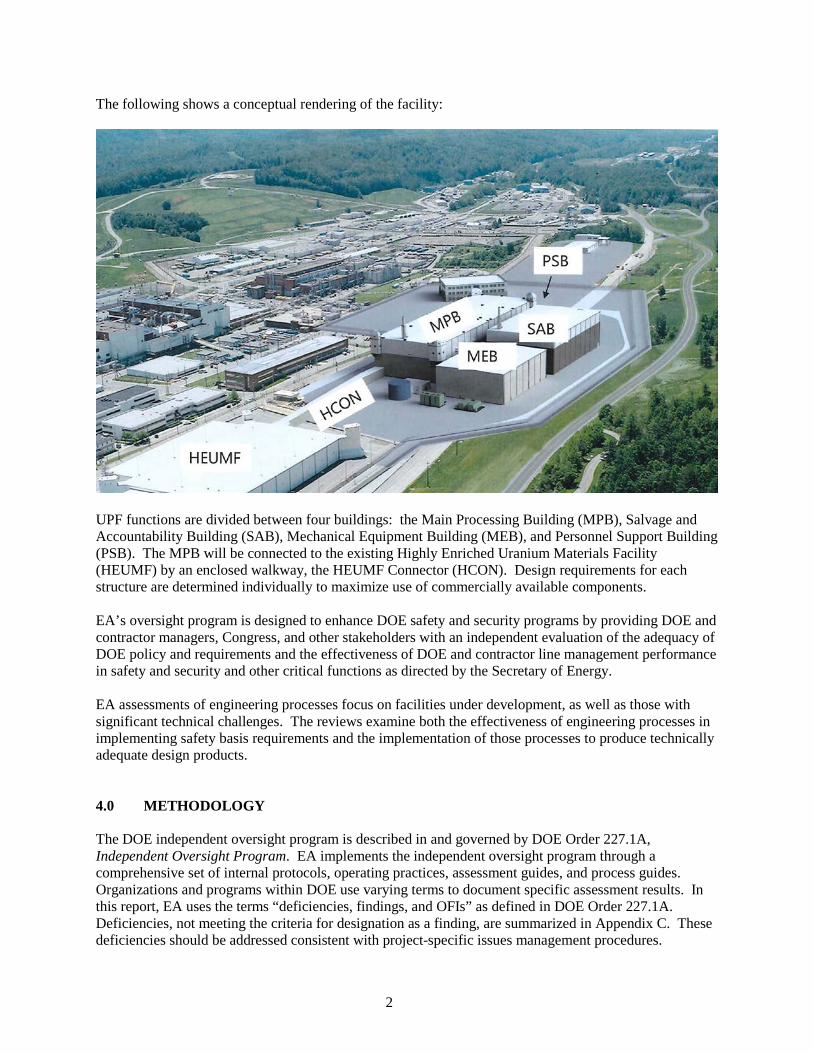
The following shows a conceptual rendering of the facility:
UPF functions are divided between four buildings: the Main Processing Building (MPB), Salvage and Accountability Building (SAB), Mechanical Equipment Building (MEB), and Personnel Support Building (PSB). The MPB will be connected to the existing Highly Enriched Uranium Materials Facility (HEUMF) by an enclosed walkway, the HEUMF Connector (HCON). Design requirements for each structure are determined individually to maximize use of commercially available components. EA’s oversight program is designed to enhance DOE safety and security programs by providing DOE and contractor managers, Congress, and other stakeholders with an independent evaluation of the adequacy of DOE policy and requirements and the effectiveness of DOE and contractor line management performance in safety and security and other critical functions as directed by the Secretary of Energy. EA assessments of engineering processes focus on facilities under development, as well as those with significant technical challenges. The reviews examine both the effectiveness of engineering processes in implementing safety basis requirements and the implementation of those processes to produce technically adequate design products. 4.0 METHODOLOGY The DOE independent oversight program is described in and governed by DOE Order 227.1A, Independent Oversight Program. EA implements the independent oversight program through a comprehensive set of internal protocols, operating practices, assessment guides, and process guides. Organizations and programs within DOE use varying terms to document specific assessment results. In this report, EA uses the terms “deficiencies, findings, and OFIs” as defined in DOE Order 227.1A. Deficiencies, not meeting the criteria for designation as a finding, are summarized in Appendix C. These deficiencies should be addressed consistent with project-specific issues management procedures.

3
Guidance for EA assessments is typically documented in a criteria and review approach document (CRAD). CRADs establish objectives specific to a review and provide a detailed listing of potential lines of inquiry for each objective. EA used CRAD 31-13, Conduct of Engineering, for this review. Consistent with the current level of engineering progress on the project, the review scope was limited to the following portions of CRAD 31-13:
• Objective 1 – Design Engineering • Objective 3 – Configuration Management • Objective 4 – Issues Management and Lessons Learned.
EA initially identified and reviewed the engineering procedures governing key processes for the development of engineering deliverables and control of the facility configuration. EA examined the flow down of safety basis requirements, both from the Conceptual Safety Design Report to the upper-tier engineering documents and from those documents to lower-tier piping and instrumentation diagrams (P&IDs), calculations, specifications, and other design documents. EA also interviewed personnel responsible for developing and executing the engineering processes, including working-level engineers who use those processes on a daily basis. Onsite activities included observing key meetings essential to the identification, coordination, and resolution of technical issues and design changes. The members of the EA assessment team, the internal Quality Review Board, and EA management responsible for this assessment are listed in Appendix A. A detailed list of the documents reviewed, personnel interviewed, and observations made during this assessment is provided in Appendix B. EA conducted a previous assessment of the UPF Project in March 2014, but did not identify any findings. Therefore, there were no items for follow-up from prior reviews during this assessment. 5.0 RESULTS 5.1 Design Engineering This section discusses EA’s assessment of engineering processes for the development of engineering input and output documents and for the capture of safety basis requirements in those documents. Inputs for this section included extensive document reviews, interviews with both working-level and management personnel, and observation of meetings. Criteria: Design engineering work is being performed consistent with technical standards, DOE requirements, and safety basis requirements and commitments, using approved procedures and sound engineering/scientific principles in accordance with the requirements of 10CFR830. Requirements Flow Down The flow down of requirements is described in PL-PJ-801768-A025, Requirements Management Plan for the Uranium Processing Facility. The flow down process appropriately integrates safety into the design process, following the document hierarchy described in PL-PJ-801768-A025. The plan also describes the strategy for how requirements are validated and verified to ensure that the completed project will satisfy its requirements. The roles and responsibilities of key organizations and key management positions in fulfilling the strategy are delineated. The Dynamic Object-Oriented Requirements System (DOORS) database is used to track requirements and their associated validations and verifications. The Systems Engineering organization is tasked by the plan with responsibility for maintaining the DOORS database

4
for UPF. DOORS is being used on other large DOE projects, including the Waste Treatment and Immobilization Plant (WTP) project at the Hanford Site, and is appropriate for use at UPF to meet the requirements of 10CFR830. Procedure UPF-3DP-G04B-00001, UPF Design Criteria, implements the flow down of requirements. As part of this procedure, the Systems Engineering Group Supervisor is charged with identifying system requirements and ensuring their entry into the DOORS database. DE-PE-801768-A001, UPF Project Design Criteria, contains Table 1, UPF Design Criteria Index, which lists the “complete design criteria” for the UPF. EA reviewed a sample of the design criteria documents, and found that they appropriately flowed down requirements from higher-tier requirements documents. The nuclear safety organization participated in the development of 19 hazard analyses and 32 individual criticality safety process studies. These analyses and studies resulted in a number of requirements that applied only to specific systems, structures, and components (SSCs). The nuclear safety organization then produced a single, consolidated document, RP-EF-801768-A059, UPF Nuclear Safety Preliminary Safety Structures, Systems, and Components, which transmitted to the design execution organization the nuclear safety requirements that impacted the completion of the preliminary design. A companion document, RP-EF-801768-A065, UPF Nuclear Safety Preliminary SSCs Providing Defense-in-Depth Functions and Risk Significant NCS SSCs, was also produced to assist the design execution organization. EA considers the consolidation of these requirements into documents useful to the design execution organization a best practice for implementation of safety in the design process. Examination of selected engineering drawings showed evidence of incorporation of criticality requirements in the dimensions of storage racks. For example, drawing M2D801768L159, Containers, Handling, and Storage - Universal Storage Rack, 12-Pos., 2X6 Assembly Layout, designates certain dimensions as being identified in the criticality safety process study for the rack system, and these requirements are summarized in RP-EF-801768-A065. EA noted similar examples on other drawings, and concluded that nuclear safety requirements are adequately flowing from requirements into design output documents. Review of Engineering Processes and Design Deliverables Calculations are defined on this project as design analyses and calculations (DACs), and are produced in accordance with APA-UPF-3DP-G04B-00037, UPF Engineering Calculations. The procedure requires design inputs to be identified, and their sources cited in the DAC. Additionally, assumptions used in the DAC are identified, justified, and then evaluated to determine whether further confirmation is required. Assumptions requiring confirmation are tracked in the Assumptions Requiring Confirmation, Data Needs, and Holds Database (ADHD). EA examined a sample of DACs to determine whether the assumptions were being tracked correctly. All assumptions requiring confirmation in the DACs were found in the ADHD system, with their status noted. EA concluded that this is an adequate method of tracking assumptions requiring confirmation. Desktop work instruction DI-EG-801768-A018, UPF Technical Issues Management System (TIMS), describes an effective process for identifying, evaluating, tracking, and closing technical issues. The process is used for a variety of technical issues, including:
• Design solutions constrained by upper-tier requirements, which require DOE approval to change. • Design solutions with significant cost or schedule impact, which need review by Engineering or
Project Management personnel before proceeding. • Extensive interdisciplinary coordination, or coordination with the project parent organization and
customer, Y-12, on issues requiring engineering or project management attention.

5
• Compliance with a code or standard that is subject to interpretation. • When early involvement of UPO is appropriate in developing a technically defensible path
forward. Weekly meetings are held to review the status of selected issues. EA observed two of the meetings and noted how the process effectively involved Y-12 stakeholders, when appropriate, and fostered productive communication between different engineering disciplines. One of the previous issues addressed by the TIMS process pertained to fire suppression in a select set of gloveboxes. Certain process gloveboxes in UPF can not use water sprinkler protection, as the activation of the sprinklers would constitute a greater hazard from potential criticality than the fire under certain conditions, requiring the use of a non-sprinkler approach. Following the TIMS process, BNI examined several alternatives and selected a hybrid fire suppression system using nitrogen gas and micro-sized water droplets that are suspended in air. The fixed volume of water in the hybrid system satisfied nuclear criticality safety concerns. Title 10CFR830.122 requires the design to incorporate appropriate standards. The hybrid system is a relatively new technology that does not have a particular National Fire Protection Association (NFPA) standard that encompasses the design and installation of such a system. The closest relevant NFPA standards are NFPA 750, Standard on Water Mist Fire Suppression Systems, and NFPA 2001, Standard on Clean Agent Fire Extinguishing Systems, although neither one addresses proper application of the standards when both a clean agent and water mist are used together. The only current applicable standard is from FM Approvals (formerly Factory Mutual Laboratories) 5580, Approval Standard for Hybrid (Water and Inert Gas) Fire Extinguishing Systems. This standard has been reviewed by the Contractor Authority Having Jurisdiction (CAHJ) and was determined to be applicable for use in these particular gloveboxes. This approval is documented in EE-EZ-801768-A008, Uranium Processing Facility Contractor Authority Having Jurisdiction Fire Protection Concurrence: Hybrid Fire Suppression System Strategy. The early involvement of the CAHJ in the use of this relatively new technology demonstrated the utility of the TIMS process. Additionally, EA observed active engagement of the BNI management team in decisions to procure engineering services from one of the qualified suppliers of hybrid fire suppression systems. EA considers the use of the TIMS process a best practice to obtain resolution of technical issues with conflicting requirements (e.g., fire suppression and criticality) that involve diverse stakeholders. The balanced ballasting ventilation header (BBVH) for passive glovebox pressure control is a novel approach for maintaining required flow velocities and differential pressures during upset conditions. This approach differs from conventional glovebox pressure control systems, which contain active components. UPF Specialty Mechanical developed DAC-EM-801768-A312, Passive Glovebox Pressure Control, to model the BBVH concept. The project also constructed and tested a prototype, as documented in RP-EM-801768-A048, Glovebox Ventilation Prototype Test Report. The DAC was subsequently revised and validated using the experimental results. Prototype testing is an appropriate method of reducing project risk associated with use of the novel passive pressure control. EA reviewed a sample of five recently developed and approved electrical DACs (2015 – 2016) to assess the adequacy of implementation of APA-UPF-3DP-G04B-00037. The procedure requires compliance with the procedure, validity and appropriateness of inputs and assumptions including justifications and references, appropriateness of analytical methods and engineering judgment, required mathematical accuracy, compliance with design criteria, completeness, and reasonableness of output data. The EA review included independent calculations and reference reviews to verify the adequacy of design inputs, assumptions, references, calculations, conclusions, and recommendations. The majority of reviewed DACs generally met the requirements of the UPF engineering calculation procedure, used the correct methods and equations, and usually resulted in appropriate and conservative conclusions and recommendations. However, contrary to the procedure, two of the five reviewed electrical DACs were

6
inadequately developed, reviewed, and approved, and did not provide valid support for some conclusions and recommendations (Deficiency):
• DAC-EE-801768-A070, VAS 3 & 4 UPS Battery Sizing Calculation, estimates of the duration the existing battery could carry the attached loads are not correct. Contrary to the DAC conclusion, the battery cannot carry the attached loads for the required 16 hours at any of the analyzed environmental conditions. At nominal conditions, the battery would be capable of carrying the required load only 92% of the necessary duration. Under predicted low temperature conditions, EA estimated that the battery would be more than 40% under-sized. The EA-identified DAC inadequacies included: o Not including the manufacturer’s specified power supply losses in the summation of battery
attached loads. o Not appropriately applying the Institute of Electrical and Electronic Engineers (IEEE) 1184,
IEEE Guide for Batteries for Uninterruptible Power Supply Systems, discharge rate temperature correction factor for the three analyzed temperature environments.
o Not adequately justifying as acceptable and conservative or bounding the assumptions that the float charged battery started at full capacity; that the use of the battery aging factor from IEEE 485, IEEE Recommended Practice for Sizing Lead-Acid Batteries for Stationary Applications, could be omitted; and that the admittedly negligible loses in the wired connection to the uninterruptible power supply could be omitted.
o Not providing appropriate references for one design input and for confirmation of one stated assumption.
• DAC-EE-801768-A074, Electrical Engineering Short Circuit Current and Arc Hazard Analysis Calculation – Post 19, contained several inadequacies requiring DAC revision. The EA-identified inadequacies included: o The DAC equation for calculating the line-to-neutral arc currents inappropriately uses the
line-to-line versus the line-to-neutral voltage. o A design input referenced the wrong circuit breaker trip characteristic curve, resulting in
under estimates of the fault current clearing time, available incident energy, and arc flash boundary for the circuit being analyzed.
o One line-to-neutral fault current and one line-to-line arc boundary calculation contained minor non-consequential errors.
o Correct values of fault current that were previously computed were appropriately used in subsequent calculations, but with minor non-consequential differences in value.
o The justification for an assumption incorrectly credited transformer secondary fuses instead of primary fuses (only primary fuses are installed) as the components most responsible for limiting fault currents, without crediting installed circuit breakers that are more effective in all but one circuit.
o The calculation did not list references to support independent verification of transformer primary voltage, power pole coordinates, or circuit lengths that were used to compute fault currents.
o A design input description referred to the wrong circuit load.
No significant concerns were identified by EA in the following reviewed DACs: • DAC-EE-801768-A064, UPF Electrical Overhead Conductor Sizing – Substation to MEB • DAC-EE-801768-A075, UPF West End Feeder Available Short Circuit Current Calculation • DAC-EE-801768-A073, Post 19 UPS Battery Sizing Calculation.
EA also reviewed a sample of DACs selected from a listing of recently issued DACs for the project heating, ventilating, and air conditioning (HVAC) systems. Requirements for the Chemical Recovery HVAC system are located in DE-PE-801768-A037, UPF Heating, Ventilating and Air Conditioning

7
Systems Design Criteria. The Chemical Recovery HVAC system provides a defense-in-depth function based on the current safety basis and hazard analyses. EA reviewed the flow down of requirements contained in the calculations and found that assumptions listed and their respective justifications utilized approved industry standards and regulations. Furthermore, EA evaluated airflow diagrams for airflow results documented in the calculations and found that they appropriately flowed down results and were captured in the system drawings. In the structural engineering area, EA reviewed the basis calculation for system interaction between the MEB building and higher-classified structures, i.e., the commodity bridge. The MEB-MPB commodity bridge spans between and is supported by the MEB and MPB. The MEB building is classified as a seismic design category (SDC)-1, limit state (LS)-B building, and the MPB building is classified as SDC-2, LS-D. The MEB-MPB commodity bridge is considered a nonstructural component and was analyzed in accordance with American Society of Civil Engineers/Structural Engineering Institute (ASCE/SEI) Standard 7, Minimum Design Loads For Buildings and Other Structures. In accordance with ASCE/SEI 7 Section 13.1.2, “the nonstructural components shall be assigned the same SDC as the structure that they occupy or to which they are attached.” Therefore, the bridge is considered SDC-2, LS-D. For the purpose of this structural engineering analysis, and though it is categorized to less severe criteria, the MEB building was analyzed using the same site-specific characterizations as the MPB. The analysis showed that the MEB will not have any system interaction with the target SSC and that there are no structural system interaction effects that would cause adverse effects to adjacent target SSCs. This approach is in accordance with American Nuclear Society 2.26, Categorization of Nuclear Facility Structures, Systems, and Components for Seismic Design, and applied a technically adequate analytical method, resulting in appropriately conservative conclusions. Based on these considerations, the structural analytical basis for the commodity bridge was adequate. EA observed the mid-job briefing for DAC-EJ-801768-A502, Recovery Furnace Backup Combustion Air. The briefing met the requirements of DI-EG-801768-A024, UPF Engineering Job Briefs, and was an appropriate follow-up to the March 2016 pre-job briefing to remind the design team of the work scope, preliminary results, and design issues of interest. The engineers decided to revise the DAC scope to use nitrogen versus air dilution and to coordinate the proposed change with the other engineering disciplines before presentation before a management of change (MOC) meeting. EA reviewed a sample of five recently (2016) developed and approved electrical field change requests (FCRs) to assess the adequacy of implementation of APA-UPF-3DP-G04B-00062, UPF FCR/FCN, and Y17-95-64-802, UPF Construction Field Change Documents. The EA review included review of the referenced drawings; the reason and description for the requested change; the assignment of Construction and Engineering Trend Codes; the UPF Technical Change Screening Form; the UPF Engineering Change Proposal (ECP), if any; and the basis for the engineering disposition. All reviewed FCRs and their associated disposition documentation appropriately met UPF procedure requirements. Further, engineering drawing E2E801768C728 was appropriately revised as required by APA-UPF-3DP-G04B-00046, UPF Engineering Drawings, after accumulating five needed changes. However:
• None of the FCRs listed a “Potential Lessons Learned,” although the need to establish consistency between design requirements for the aerial cable connecting two 240 volts alternating current panels by changing the one-line drawing conductor label from a Triplex to a Quadruplex service drop cable (as required by NFPA 70 and requested by FCR-CM-801768-P19-A012) warrants further consideration as a lessons learned. When EA asked the engineer, who dispositioned the reviewed FCRs and who had reportedly been on site for less than a year, why no lessons learned were identified, the engineer indicated in error that he did not believe UPF had a lessons learned program.
• The assigned Engineering Trend Code of C.1 for FCR-CM-801768-P19-A012 and -A015 corresponds to a title of “Design Error or Omission;” however, both FCRs requested resolution of

8
conflicts in conductor specifications documented on engineering design drawings, corresponding to a C.2 trend code with a title of “Design Conflict.”
EA also reviewed RP-EM-922600-A018, Engineering Study for Pickling Glovebox Electrical Load Tabulation, to determine its purpose and whether the methods used for development were appropriate. The stated purpose of the tabulation is to provide support to development of electrical system sizing and design and for development of process heat load calculations. The design deliverables were tabulations of connected electrical loads, summary of uninterruptible power supply and normal power loads, heat loads outside the glovebox, and heat loads inside the glovebox. The information to populate the tabulations was appropriately derived from specified datasheets, electrical and instrumentation and control drawings, engineering specifications, and NFPA 70 estimates. EA concluded that the methods used to develop the resulting tabulations were adequate. Design Engineering Conclusions Overall, the BNI engineering processes and procedures reviewed are adequate to ensure design requirements are incorporated into design output products. Nuclear safety requirements were appropriately included in reviewed design drawings. A systematic method is used to track and close unverified assumptions in DACs. EA considers the compilation of nuclear safety requirements into a single reference for safety-significant SSCs and a second single reference for risk-significant and defense-in-depth SSCs to be a best practice. EA also considers the TIMS process as a best practice for resolving issues of conflicting requirements. Actions taken by BNI management to reduce the risk associated with two novel technologies were appropriate. Engineering design deliverables reviewed by EA generally met the requirements of UPF procedures, used the correct methods and equations, and usually resulted in appropriate and conservative conclusions and recommendations. However, EA identified a few inadequacies that evidenced inattention to detail on the part of the originators, reviewers, and approvers in some of the affected documents. BNI engineering personnel were receptive to the feedback provided, and revision of several affected documents began before EA left the site. 5.2 Configuration Management This section discusses EA’s assessment of the UPF configuration management (CM) program with a focus on engineering change control processes and document management processes. Criteria: A documented configuration management (CM) program has been established and implemented in accordance with DOE O 420.1 that ensures consistency among system requirements and performance criteria, system documentation, and physical configuration of the systems within the scope of the program. DOE STD 1073-2003 provides an acceptable methodology to accomplish this requirement and may be invoked contractually on the specific facility. Design Requirements As noted previously, design engineering for UPF is estimated to be just over 60% complete. Most drawings and calculations are in “Preliminary” status. Efforts are underway to re-issue P&IDs and ventilation and instrumentation diagrams (V&IDs) and their supporting analyses/calculations in numeric revision (“Committed” or “Confirmed”) status, which would support downstream issuance of design output drawings in “Issued for Construction” status. EA concluded that this process is well defined and

9
that requirements for design input and output documents are well established. The processes used to establish the design baseline are adequate, an important first step in the CM process. APA-UPF-3DP-G04B-00005, UPF Configuration Management, is a high-level procedure that establishes the Technical Change Control Board (TCCB) for review and approval of design changes. It also mandates development of a Configuration Management Plan addressing the CM requirements of DOE Order 413.3B and DOE Standard 1073-2003. PL-PM-801768-A052, UPF Configuration Management Plan, was issued in late 2015 as a result of those requirements. The UPF CM Plan is a comprehensive but also high-level description of the roles and functions of a CM program, stating what the program must accomplish but relying on other implementing procedures to establish actual requirements. Both the CM Plan and implementing procedure APA-UPF-3DP-G04B-00901, UPF Technical Change Control, state that the change control process will apply to documents that have attained numeric revision status. However, in addition to the formal change control process documented in APA-UPF-3DP-G04B-00901, BNI has implemented an informal change control/coordination process applicable to documents in Preliminary status. The informal process will be discussed below, followed by a discussion of the formal process. MOC Process With the UPF design effort just past its midpoint and most documents still in Preliminary status, industry practice would not drive any change control process to be strictly or pervasively applied due to the limited risk and benefits involved. However, BNI has implemented a process controlled by desktop instruction DI-EG-801768-A030, UPF Management of Change. It is an informal process, applicable to documents in Preliminary status, which requires coordination of change impacts between potentially affected disciplines and results in impact estimates that are reviewed in the weekly MOC meeting. Once a change is approved in the MOC meeting, the affected disciplines are expected to coordinate updates to their affected documents. (The MOC form does not require a listing of affected documents, and MOC-submitted changes are not tracked electronically against affected documents as discussed below in the more formal ECP process.) Impacts may be varied, including both affected design documents and resources (manpower/budget). EA observed two MOC meetings, finding them effective in promoting discipline interaction. Operations, Maintenance, and Security were represented at both meetings and actively participated. Engineering disciplines are expected to track impacts to documents using the project schedule; however, interviews indicated that this practice is not universal, and new schedule activities are generally not added if the project schedule already has an activity to revise an affected document at some future date. Some disciplines had informal methods of tracking impacts, but at least one discipline did not track impacts at all. This issue was identified during EA’s review of MOC-EJ-147, SOX Rev 1 PFD Comment Review Modifications. That MOC form was approved in January 2016 and noted that calculation DAC-EJ-801768-A139 would be impacted. Discussions with the affected discipline indicated that the calculation was not scheduled to be revised until December 2016. Despite this 11-month gap between the design change and the calculation revision, EA found that the affected discipline had no tracking mechanism in place and no other means of ensuring that the change requested in the MOC would be incorporated into the next revision of the calculation. Based on information provided during the review, other disciplines on the project have informal tracking mechanisms in place, indicating that the discipline involved with this MOC was an outlier in its failure to track MOC commitments. Overall, EA found that the informal MOC process does drive good communication between disciplines and provides an important coordination function at a point in the project where formal design change control would not normally be in place. However, the effectiveness of the MOC process suffers from inconsistent rigor in the tracking of impacted document revisions to completion.

10
ECP Process BNI engineering management indicated that the MOC process will be superseded by the ECP process as documents transition from Preliminary (alpha revision level) to Committed or Confirmed (numeric revision level) status. As mentioned above, the ECP process is defined in APA-UPF-3DP-G04B-00901. ECPs are evaluated and approved at the weekly meeting of the TCCB. EA observed a TCCB meeting and noted active participation by representatives of several disciplines and both Operations and Maintenance. Currently, the ECP process has limited applicability only to primary documents that have attained numeric revision status and that have been submitted and authorized by NNSA for construction, installation, or procurement activities. This group of documents includes upper-tier engineering documents, down through the document hierarchy provided in PL-PJ-801768-A025, to the level including P&IDs, V&IDs, and electrical single line drawings, and a very small population of material and energy balance calculations. EA identified several aspects that render the ECP process ineffective and have the potential to create problems in documents used to support construction and that do not meet the requirements of DOE Standard 1073-2003 (Deficiency):
• The ECP process has limited applicability as described above, i.e., it does not apply to engineering documents below the primary drawing level in the project document hierarchy.
• A project engineer can waive impact assessments on Class 2 ECPs, which are changes to primary documents such as P&IDs and electrical single lines. UPF-3DP-G04B-00922, UPF Impact Assessment, defines the impact assessment process. Changes to these documents may have substantial consequences.
• The Safety in Design Integration Team chairman may waive the impact assessment process for Class 1 Type 2 ECPs, which are used to revise certain upper-tier requirements documents. Again, changes to these documents may have substantial consequences.
• The ECP Form has a place to list affected documents, but there is no procedural requirement to identify them. Section 9.1.3.4 of PL-PM-801768-A052 requires identification of affected documents as part of the information required to review and approve a change.
• The closure process does not specify whose responsibility it is to ensure affected documents get changed. For Class 2 ECPs, APA-UPF-3DP-G04B-00901 requires the project engineering manager or project engineer to verify incorporation of changes to affected documents before closure. This requirement does not exist for Class 1 ECPs, a violation of requirements stated in Section 3.4 of APA-UPF-3DP-G04B-00005.
Document Control In examining the UPF records management system, EA reviewed document control processes to determine whether:
• The system provides the latest version of requested documents and includes available access to prior revisions.
• Metadata stored in the system for a document includes relations to predecessor and successor documents.
• The system tracks unincorporated changes against a document and makes that information available to the requestor.
• The system limits excessive unincorporated changes.

11
Preliminary engineering deliverables are typically stored within the engineering organization using ProjectWise® software. Documents, such as calculations in ProjectWise®, may be modified directly without the use of formal or informal change processes. Documents in this status may not be used for final design or construction. This approach is adequate for documents in this status. Rigorous document control is implemented once a deliverable reaches Committed or Confirmed status as evidenced by a numeric revision level. InfoWorks® is the formal records management software for the project. Based on the procedures reviewed, EA concluded that InfoWorks® complies with most of the requirements noted above. The latest version of an issued document is easily available. Section 9.1.3.4 of PL-PM-801768-A052 notes that, “ECPs, FCRs, NCRs, SDDRs, DCNs and Specification Addenda are posted against the latest revisions of their associated affected documents in the document management system to maintain the current document configuration.” PL-PM-801768-A052 also summarizes limits in place on outstanding changes, which EA found were also defined in other procedures specific to various document types such as drawings. EA noted two concerns with the document control process:
• Although InfoWorks® tracks outstanding changes against issued documents, incorporation of those changes during a revision to the document is not mandatory. If not incorporated, a change will continue to be tracked until it is eventually incorporated. This is a weakness in the change management program, since the affected document could be changed in a manner that affects the unincorporated change.
• Currently, when documents are entered into InfoWorks®, relationships are not created with predecessor and successor documents as required by Y15-95-800, UPF Document Management, Section 4.5, which directs document management personnel to “Build relationships to other documents, if applicable, using the configuration management module of InfoWorks®.” The absence of predecessor and successor relationships in a records management system significantly weakens the process of identifying affected documents during the design change process. For instance, when a calculation uses design input from another calculation, if those calculations are not linked in InfoWorks®, the impact on the downstream calculation cannot be evaluated if the upstream calculation is subsequently revised.
Configuration Management Summary The production of design deliverables is well controlled, with an informal change process for preliminary documents that was positive in driving interdisciplinary communication and coordination. Participation by Operations and Maintenance personnel in deliberations over proposed design changes and in resolution of technical issues was noteworthy. Use of project engineers who are assigned responsibility for individual buildings was effective in exerting positive control of the change process during the preliminary design stage. However, EA concluded that the ECP process implemented for a limited population of documents was ineffective. EA also noted two areas in records management that were also not fully effective. 5.3 Engineering Performance Oversight and Improvement Programs This section discusses EA’s assessment of UPF issues management processes, training programs, and lessons learned processes related to engineering. This portion of the assessment includes an examination of the UPO oversight process for engineering. Criteria: Programs and processes are in place to identify and correct problems, ensure that personnel are appropriately trained and qualified, and assess internal performance, identifying lessons learned and

12
implementing appropriate corrective actions. [DOE Order 414.1D, Quality Assurance, and DOE Order 210.2A, DOE Corporate Operating Experience Program] Issues Management BNI manages UPF Project issues using Y-12 Procedure Y15-312, Issues Management Process, with specific supplemental instructions for the UPF Project in Y15-95-312, UPF Supplemental Procedure for Issues Management, Change Notice 2. These procedures include the essential elements of a satisfactory process: issue origination, scoping, closing, and tracking; assignment of ownership; determination of significance; causal analysis; development and verification of corrective actions; and trending. The procedures define four levels of significance (“A” through “D” with Level A being the highest significance, warranting rigorous application of all of these elements). For example, causal analyses and extent-of-condition reviews are typically only performed for Level A or B issues. BNI assesses data to ensure that project team members proactively identify performance risks and prevent errors, rework, and recurring issues. The results are provided in the Quarterly Quality Trend Report. These reports assess the number of entries in the Issues Management System (IMS), including how many were self-identified; the timeliness of causal analyses; CAPs and issue closure; trends in IMS entries (including Level D issues); lessons learned entered; and data based on interviews to assess how the behaviors or attitudes of the workforce align with management’s expectations (e.g., for conducting adequate pre-job planning and stopping work when necessary). The Quarterly Quality Trend Report for the first quarter of fiscal year (FY) 2016 adequately identified details regarding issues management by the project. For example,
• The number of issues entered into the IMS increased significantly in the first quarter of FY 2016 (i.e., 65 issues compared to 35 for the previous quarter), but is still below BNI management’s expectations of the number of issues that should be identified, considering the phase and size of the UPF Project.
• The average time to close an issue was 102 days, as compared to 213 days in the previous quarter. This timeframe still exceeds the project goal of 90 days.
The Quarterly Quality Trend Report for the first quarter of FY 2016 also identified that improvement was needed with higher significance (e.g., Level B) issues to improve the timeliness of the development of causal analyses and the resultant CAPs based on the following.
• CAPs were being inappropriately reported complete for Level B issues, with an action to subsequently complete the causal analysis and identify corrective actions to address the identified causes. Accordingly, in May 2016, BNI began reporting CAPs complete after identifying the actions based on the completed causal analysis to provide better indications to BNI management of the status of the complete CAP development.
• Average time to develop the causal analyses was 100 days, which exceeds the BNI UPF Project management goal of 45 days.
BNI appropriately entered an issue into its IMS (IMS 31606359) to improve the timeliness of its causal analyses. The actions correctly included the development of UPF training and qualifications for causal analysis facilitators and a desktop instruction to streamline the process and to identify key hold points for management briefings and alignment with the assigned causal analysis team. Following completion of the corrective actions, the first causal analysis was timely in that it was completed within 28 days. BNI is currently developing a formal lessons learned report based on these improvements. BNI also formed an Issues Review Board (IRB) to improve the management of issues. The IRB meets weekly and monitors the number of Level A, B, and C issues initiated for each month (including how

13
many were self-identified); the quality and development of causal analyses and CAPs; and CAP execution (with focused discussions on actions due within the next 30 days). Overall, EA considers BNI issues management adequate and improving due to proactive management involvement. EA’s review of the quarterly reports over the past year and observations from two IRB meetings noted the following as areas not fully effective:
• BNI has not issued Quarterly Quality Trend Reports in a timely manner. Separate reports were not issued for the first or second quarter of FY 2015; instead, the report for the third quarter of FY 2015 assessed and documented data from the first half of FY 2015. The reports for the third quarter and fourth quarter of FY 2015 and the first quarter of FY 2016 were issued three to four months after the end of the quarter, reducing the value of the analysis. The report for the second quarter of FY 2016 remained incomplete at the conclusion of the EA site visit.
• Despite messages issued by BNI project management (i.e., an email from the BNI Project Director in April 2015 and two from the BNI Project Manager for Execution posted to the UPF webpage in the fall of 2015 and spring of 2016), the number of issues being reported continues to be below BNI management’s expectations. (See OFI-BNI-1.)
o The number of lower-level issues should be greater than that of higher-level issues (e.g., the percentage of Level D issues should be greater than the percentage of Level C issues). The distribution of the significance levels reported by the Quarterly Quality Trend Report for the first quarter of FY 2016 (i.e., 42% Level D, 52% Level C, and 6% Level B) is another indication of the under-reporting of lower-level issues that has not been recognized or resolved by BNI UPF project management.
o A surveillance by BNI Quality Assurance (QA) personnel in November 2015, documented in ISR-QA-801768-FY16-002, identified “that issues are seldom identified by individuals performing work outside of formal assessment, surveillance, or audit process” which “may indicate broader issues related to the awareness of how issues should be identified or the lack of a strong issue reporting culture.” Four of eight personnel interviewed for this UPF QA surveillance were unaware of the IMS, and two of eight were unaware of the IRB.
o Two of 12 engineers interviewed by EA were unaware of the IMS or the IRB. These two engineers had been with the UPF Project for less than six months. These engineers had taken the UPF Project Orientation course, PRES-PS-801768-A002, which includes a brief discussion on the importance of identifying issues.
EA’s review of CAPs for select engineering issues identified problems in the development of immediate actions to prevent further deviations until actions to correct the cause of the issue are implemented and/or in the development of actions to prevent recurrence per Y15-312 (Deficiency). Specifically:
• IMS 31328462, Prototype Microwave Caster Glovebox Design Not Acceptable, was opened on October 2, 2014, to address “an Engineering decision to waive design coordination” processes for the design of the prototype microwave caster glovebox, rather than accelerate implementation of design coordination to meet the required timeline for prototype fabrication. Although the design issues were ultimately resolved to support prototypic testing, the incomplete coordination of the design (e.g., incomplete comment resolution) early in its development led to additional iterations as the design was being finalized. This issue was closed on January 14, 2016, 462 days after being opened; however, approximately two and a half months later, BNI discovered that issues with the coordination and alignment of expectations continued between the engineering groups supporting glovebox design and integration efforts. BNI UPF Engineering identified in the causal analysis for the subsequent issue (documented in IMS 31607264, Glovebox Structural Design Assumption Not Defendable) that of the 16 corrective actions in the CAP for IMS 31328462, only three implemented sustainable mitigation of recurrence. Five were cancelled by management;

14
four were one‐time briefings or memos that captured only the audience at the time and were not institutionalized, which would have helped prevent the continued issues in the coordination of glovebox design and integration efforts. EA concluded that no actions resulting from IMS 31328462 were established to prevent recurrence of the broader cause of the incomplete coordination of the design and alignment of expectations as required by Y15-312.
• IMS 31607264 was opened on March 31, 2016, to address the continued differing expectations on level of detail and acceptable basis for making decisions on the glovebox design (e.g., whether formal calculations are needed or whether engineering judgment and experience is sufficient for different design decisions). Long-term corrective actions to ensure alignment for issued, in-progress, and planned glovebox design work were originally scheduled for May 26, 2016, but have been delayed to at least June 30, 2016, three months after the origination date. Immediate actions to “reinforce team to ensure assumptions are properly justified” are vague and do not provide assurance that ongoing work on drawings and calculations by the approximately 100 engineers continuing to develop design deliverables for the glovebox is acceptable. Therefore, the immediate actions for this issue do not “temporarily control the Issue/event and prevent further deviations” per the guidance of Y15-312 to minimize the potential rework required until actions to address the cause of the issues are implemented.
• BNI surveillance MSR-PM-801768-FY16-016 assessed the implementation of the new UPF procedure for engineering calculations (APA-UPF-3DP-G04B-00037, effective August 31, 2015). It did not review the accuracy of the calculations. This surveillance reviewed 24 calculations from different engineering disciplines and determined that the new procedure was being effectively implemented, but identified “a number of issues.” These issues are indicative of poor attention to detail by the originator, checker, and supervisors reviewing the calculations. Issues identified by the BNI surveillance were entered into seven IMS Level C and D entries. Y15-312 allows management to establish immediate actions for Level C issues. However, no immediate actions were established to improve attention to detail for calculations, while another evaluation of 25 more calculations was performed with a scheduled completion of two months later on June 1, 2016. As discussed in the section of the report on Design Engineering, EA review of electrical calculations subsequently identified additional instances of poor attention to detail, including calculation errors, in electrical calculations performed since the surveillance was issued. A key corrective action to improve the quality of engineering calculations by issuing an Engineering Quality bulletin has been delayed from June 1, 2016, to June 22, 2016.
Performance Assessment Overall BNI UPF Project performance relative to the quality of project work is managed utilizing metrics per Y-12 Program Description Y15-908PD, Y-12 Performance Metrics Program. On a monthly basis, the “UPF Project Quality Dashboard Metrics” are reviewed by project management to ensure that the UPF Project’s goals for these metrics are met. These metrics include a mix of lagging and leading indicators based on reviews of issued and in-process work and qualitative metrics based on interviews to assess how the behaviors or attitudes of the workforce align with management’s expectations (e.g., for conducting adequate pre-job planning, stopping work and reporting issues). The metrics for UPF Engineering performance have predominately been within the UPF Project’s goals over the past year, and the UPF Project has proactively initiated action to investigate adverse trends in the metrics for engineering performance. EA’s review of quality dashboard metrics for April and May 2016 noted that monitoring and assessment of the performance of UPF engineering is generated by averaging data from over 600 engineers. Use of discipline-specific data for performance monitoring on a smaller scale is sporadic. (See OFI-BNI-2.) Specifically:
• None of the performance metrics of the UPF Project Quality Dashboard provide indications of the performance of the over 50 nuclear safety engineers on the UPF Project team. The UPF Project

15
Engineering Manager for Nuclear Safety Engineering utilizes qualitative assessments of performance based on supervisory reviews of work products and comments from external reviews of the group’s safety basis documents in lieu of more structured performance metrics. The identification of performance issues during supervisory and external reviews that are obtained later in the safety basis documentation process delays the start of corrective actions and increases the iterations in the UPF design and safety basis development.
• BNI does not typically perform assessments of overall performance within individual engineering disciplines and smaller engineering groups. For example, the Senior Engineering Group Supervisor for electrical engineering was the only supervisor interviewed who uses the database information on independent checking of design deliverables to look for trends in performance of the personnel assigned to him.
Y60-95-102PD, UPF Quality Assurance Program Description, states that BNI management assessments and independent surveillances (i.e., audits by independent QA personnel) are used by BNI to “evaluate whether processes are effective and efficient and meet specified requirements.” Management assessments are specifically described as “a self-analysis tool that may be used to evaluate all aspects of performance and to determine whether the management infrastructure is properly focused on desired results.” Surveillances (other than surveillances performed by independent QA personnel as audit equivalents, as discussed above) “may be used to supplement the organizational management and/or independent surveillance/audit programs to verify conformance of items and work processes to specified requirements.” EA’s review of the BNI assessments and surveillances of UPF Engineering identified the following:
• Assessments and surveillances performed in FY 2015 and 2016 were based on project needs, risk, issues, and management input as stated in Y60-95-102PD. For example, UPF Engineering scheduled surveillances of training and new procedure Y90-95-027, UPF Training Program, following its issuance in September 2015, to proactively evaluate the implementation of this significant revision to the UPF training program.
• BNI UPF Engineering has primarily used surveillances to assess its performance, which is contrary to the statements in Y60-95-102PD that surveillances are used “to supplement the organizational management and/or independent surveillance/audit programs.” Specifically, in FY 2015 and FY 2016, UPF Engineering personnel performed 24 surveillances. BNI had not performed any management assessments in FY 2015 and had performed only one to date in FY 2016. That management assessment was focused on subcontract administration rather than on evaluating the engineering organization’s overall performance and progress towards strategic goals and project milestones. UPO also identified that QA personnel had performed no management assessments in FY 2015 (Deficiency).
• BNI personnel in the nuclear criticality safety discipline had conducted only one surveillance and no management assessment since the beginning of FY 2015 despite the significant impact undetected or lingering issues with their work can have on the UPF design.
Engineer Training and Qualification UPF procedure Y90-95-027 was issued on September 1, 2015, and implemented a more systematic approach for defining required training and maintaining the competency of personnel commensurate with their assigned responsibilities. Rather than assigning specific training requirements for each individual, as had been done previously, general and specific Training Position Descriptions (TPDs) were developed to more easily establish common training requirements across large groups of personnel and more focused training requirements for smaller groups. For example, a TPD was developed to define the required training and required reading for any engineer on the UPF Project, and requirements specifically for

16
electrical engineers were on a separate TPD. Each electrical engineer would have both of these TPDs on his/her Position Assignment Form, as well as other applicable TPDs and any specific training or reading required by the supervisor, commensurate with assigned duties. Updates to training and required reading are also more easily distributed by issuing revisions to the TPDs. The UPF training database notifies personnel of the revised training/reading requirements and tracks their completion. Y90-95-027 also states that notices are issued for delinquent training and, until training requirements are satisfied, the employee duties are restricted or supervised by a fully trained person in the area of deficiency. A surveillance conducted by the BNI UPF Training Manager in October 2015, documented in MSR-PM-801768-FY16-009, identified delays in the implementation of Y90-95-027. Specifically, supervisors had discussed the new training requirements with only 60% of the personnel interviewed and only 50% of Position Assignment Forms had been completed. A subsequent surveillance conducted by engineering personnel in January 2016 identified that the systematic approach of the new Y90-95-027 had improved training overall and that Position Assignment Forms had been completed for all engineers. During interviews with engineers, engineering supervisors, and the BNI UPF training managers, EA confirmed that the Position Assignment Forms were adequately complete and that qualification and training requirements were also reviewed during pre-job briefs to ensure personnel were properly trained for these specific jobs. The EA team also observed a BNI UPF Project Orientation Briefing and engineering training on the UPF Project’s graded approach to quality, engineering calculations, development of engineering design deliverables, and the design verification procedure. Although the training is adequate, EA observed a few areas where the engineering training was not fully effective:
• The presentations for the engineering training were rushed, covering 30 to 60 slides in an hour. • The engineering training was only minimally interactive. Despite not administering a test or quiz
for any of the engineering training classes, the instructor did not ask the participants adequate questions to ensure the participants understood key aspects from the training. For example, the instructor did not ensure that participants adequately understood the differences between the processes and expectations for nuclear and non-nuclear work, and the reasons for these differences. Only approximately 25% of the participants in the engineering training classes had previously worked on a nuclear project.
• IMS 31457832, Minor DAC Inaccuracies, stated that rigor and attention to detail for calculations for nuclear work would be covered in the training on engineering calculations. The instructor for the training stated that he was unaware of this IMS entry, as well as the expectation to include the level of detail discussed in IMS 31457832 in the training on engineering calculations.
Lessons Learned BNI developed Y15-95-331, UPF Project Lessons Learned Program, to supplement the requirements in Y-12 Procedure CNS WI 02.03.04.01.20, (U) Using the Lessons Learned Program, to meet the requirements of DOE Order 210.2A. The UPF Lessons Learned Program Coordinator screens lessons learned from within the DOE complex and commercial industry for applicability and further evaluation by UPF subject matter experts and management. These evaluations and resultant actions are tracked in a specific section of the Project Action Item List (PAIL). The UPF Lessons Learned Program Coordinator also issues an annual report on his assessment of the lessons learned program. The FY 2015 lessons learned report for the UPF Project, LL-PS-801768-A025, appropriately determined that the lessons learned program supports the goal of proactively identifying lessons learned to prevent errors, rework, and recurring issues. During FY 2015, a total of 52 lessons learned were entered into the UPF database, 22 (42%) were self-identified and 30 (58%) were from external sources. Of those, engineering had the majority with 27 lessons learned. The number of lessons learned entered also

17
significantly increased in FY 2015 and represents 58% of the lessons learned generated over the past four fiscal years. In this FY 2015 report, the project continues to encourage learning by continuing to seek lessons from others (especially from within Y-12, the WTP Project, and BNI) and transferring personnel with relevant experience from similar projects (e.g., HEUMF and WTP). EA considers the UPF lessons learned program effective and notes the following:
• Project personnel participated in briefings of WTP lessons learned for BNI executive management and had more focused discussions to reflect lessons more directly applicable to the UPF. The results of these reviews were documented in WP-PM-801768-A009, Uranium Processing Facility Lessons Learned from the Waste Treatment and Immobilization Plant Project. PAIL tracks actions generated from these reviews, along with an action to annually review WTP lessons learned to reassess their applicability.
• The PAIL includes actions based on WTP lessons learned on procurements identified during the review discussed above and initial UPF lessons learned on the coordination between BNI UPF engineering and procurement personnel (including those overseeing supplier quality).
Federal Oversight Per DOE Order 226.1B, Implementation of Department of Energy Oversight Policy, UPO developed UPO-PL-95-A005, UPF Project Office Oversight Plan, to evaluate the prime contractor’s oversight and assurance programs and to independently evaluate the prime contractor’s performance. The UPO FY 2016 Master Assessment Schedule has a relatively large number of assessments scheduled on BNI UPF Engineering (i.e., 24 out of 72), which include an adequate mix of independent reviews, reviews performed concurrently with the contractor and external assessors to appropriately utilize UPO resources, and self-assessments of UPO performance. UPO issues a quarterly report summarizing its performance to its master assessment schedule. The report issued for the first quarter of FY 2016 (ASRP-QA-4.8.2016-672340, dated April 8, 2016) identified that seven of the 14 assessments scheduled were completed, five were extended with due dates beyond the first quarter (three of these five are concurrent reviews with scheduling controlled by other organizations), one was cancelled, and one was late. UPO also completed 12 assessment activities not on the FY 2016 Master Assessment Schedule. The UPO quarterly report concludes that the planned and additional oversight activities are appropriately focused on environmental, safety, and health, construction, and engineering functions considering the stage of the project. EA concluded that UPO oversight activities are appropriately focused, but noted that the quarterly report was issued three months after the end of the quarter. This delay and the backlog of scheduled oversight activities from the first quarter of FY 2016 tend to reduce the value of the report. EA also reviewed UPO involvement in formal design reviews of engineering deliverables. Specifically, EA reviewed ASRP-ENG-8.24.20J5-639745, UPO Site Preparation and Long Lead Procurement Final Design Review Report, and COR-ENG-3.1.2016-666387, Contract DE-NA-0001942, Uranium Processing Facility Project Office Assessment of the Mechanical/Electrical Equipment Building Slab and Shell Final Design. Early in its review of the site preparations, UPO identified that the design package initially provided was inadequate to support the review and took proactive action to ensure adequate information was provided to support this review and subsequent design reviews. For both of these assessments, UPO performed thorough concurrent design reviews with the prime contractor and independently assessed the mechanical/electric building design capability to support subsequent SSC design efforts, future growth, alignment with the Conceptual Safety Design Report, and security requirements.

18
Engineering Performance Oversight and Improvement Programs Conclusions BNI adequately monitors overall UPF Project performance with its dashboard metrics and Quarterly Quality Trend Reports and its management team’s involvement has improved the management of issues for the UPF project. EA, however, identified that actions to date have not been effective at increasing the identification and reporting of issues to meet UPF Project management expectations and that several immediate and corrective actions for engineering issues have been inadequate to preclude recurrence and rework. EA also identified that existing capabilities and management assessment processes are typically not utilized to assess the performance of individual engineering disciplines or groups of engineers by the responsible supervisors. BNI has also taken actions to improve engineering performance for the UPF Project. The UPF lessons learned program is effective at proactively evaluating lessons from similar work for applicability to the UPF project. The UPF Project performed extensive, formal reviews of lessons from WTP and scheduled annual reassessments of the WTP lessons as the UPF design proceeds. The new UPF training program is an improved, systematic approach for effectively managing training across the large number of engineers assigned to the project. EA, however, identified areas where the key aspects of engineering training may not be fully understood by participants.
The UPO has an extensive set of assessments planned to oversee BNI UPF Engineering functions and has provided technically thorough, independent and concurrent assessments during formal UPF design reviews. 6.0 FINDINGS EA identified no findings during this assessment. Deficiencies that did not meet the criteria for a finding are listed in Appendix C of this report, with the expectation from DOE Order 227.1A for site managers to apply their local issues management processes for resolution. 7.0 OPPORTUNITIES FOR IMPROVEMENT EA identified some opportunities for improvement (OFIs) to assist cognizant managers in improving programs and operations. While OFIs may identify potential solutions to findings and deficiencies identified in appraisal reports, they may also address other conditions observed during the appraisal process. EA offers these OFIs only as recommendations for line management consideration; they do not require formal resolution by management through a corrective action process and are not intended to be prescriptive or mandatory. Rather, they are suggestions that may assist site management in implementing best practices or provide potential solutions to issues identified during the assessment. Bechtel National, Incorporated OFI-BNI-1: Since the current approach utilizing management memoranda has proven ineffective, BNI
management should consider emphasizing the role of first line supervisors in reporting and trending lower-level problems, allowing the supervisors and other managers to more proactively resolve issues and improve performance.
OFI-BNI-2: BNI should consider having engineering managers and supervisors periodically (e.g.,
annually) assess their performance to the UPF Project’s performance goals and future design milestones and more frequently (e.g., monthly) monitor their performance through

19
discipline-specific metrics. 8.0 ITEMS FOR FOLLOW-UP Based on the results of this assessment, further review is warranted in the area of design control and configuration management to ensure that additional rigor is applied as the facility design is finalized and physical construction progresses.

A-1
Appendix A Supplemental Information
Dates of Assessment Onsite Assessment: May – June, 2016 Office of Enterprise Assessments (EA) Management
Glenn S. Podonsky, Director, Office of Enterprise Assessments William A. Eckroade, Deputy Director, Office of Enterprise Assessments Thomas R. Staker, Director, Office of Environment, Safety and Health Assessments William E. Miller, Deputy Director, Office of Environment, Safety and Health Assessments Patricia Williams, Director, Office of Worker Safety and Health Assessments Gerald M. McAteer, Director, Office of Emergency Management Assessments
Quality Review Board
William A. Eckroade John S. Boulden III Thomas R. Staker William E. Miller Patricia Williams Gerald M. McAteer Michael A. Kilpatrick
EA Site Lead for the UPF Project
Jimmy Dyke
EA Assessors
Charles Allen – Lead Timothy Martin Joseph Probst Samina Shaikh Gregory Teese

B-1
Appendix B Key Documents Reviewed, Interviews, and Observations
Documents Reviewed APA-UPF-3DP-G04B-00005, Revision 0, 3/13/2015, UPF Configuration Management APA-UPF-3DP-G04B-00025, Revision 0, UPF Engineering Interface Control APA-UPF-3DP-G04B-00037, Revision 0, UPF Engineering Calculations APA-UPF-3DP-G04B-00046, Revision 0, UPF Engineering Drawings APA-UPF-3DP-G04B-00047, Revision 1, UPF Engineering Deliverables to Procurement, Construction, and Startup APA-UPF-3DP-G04B-00049, UPF Engineering Specifications, Revision 0, 8/31/2015 APA-UPF-3DP-G04B-00062, Revision 0, UPF FCR / FCN APA-UPF-3DP-G04B-00901, Revision 0, 10/15/15, UPF Technical Change Control CNS CD-0029, Quality Assurance Program Description, Issue No. 001, 3/10/2016 Control of Nuclear Gloveboxes and Enclosures Using the No-Moving Part Vortex Amplifier (VXA), 2/25/2007 Cooper Bussman Handbook SPD Electrical Protection Handbook Based on the 2014 NEC Cooper Bussman, Bulletin EPR-1, Electrical Plan Review CSPS-EN-801768-RACK-B001, Nuclear Criticality Safety Process Study of Racks, Revision A, March 2016 D2E940427A001, General Arrangement Fire Tank Pump Building, Revision 0, 5/5/2016 D2E942600A002, General Arrangement Mechanical/Elect Equip Bldg Second Level, Revision 0, 5/28/2015 D2E942600A003, General Arrangement Mechanical/Elect Equip Bldg Section View A-A & B-B, Revision 0, 5/28/2015 D2E942600A004, Piping Orthographic Mech/Elect Equip Bldg First Level, Revision 0, 11/13/2015 D2E942600A005, Piping Orthographic Mech/Elect Equip Bldg First Level, Revision 0, 11/13/2015 D2E942600A006, Piping Orthographic Mech/Elect Equip Bldg Second Level, Revision 0, 11/13/2015 D2E997706A001, General Arrangement UPF Process Gas Yard NN, NA, NH Gas Tanks & Trailers, Revision 0, 5/18/2016 DAC-EJ-801768-A139, Revision 0, 2/5/2014, Furnace Functional Analysis DAC-EE-801768-A064, Revision 0, UPF Electrical Overhead Conductor Sizing – Substation to MEB DAC-EE-801768-A070, Revision 0, VAS 3 & 4 UPS Battery Sizing Calculation DAC-EE-801768-A073, Post 19 UPS Battery Sizing Calculation DAC-EE-801768-A074, Revision 0, Electrical Engineering Short Circuit Current and Arc Hazard Analysis Calculation – Post 19 DAC-EE-801768-A075, UPF West End Feeder Available Short Circuit Current Calculation DAC-EH-801768-A401, Airflow/C&H Calculation – MPB, SOX, Revision A, 12/4/2014 DAC-EH-801768-A402, Airflow/C&H Calculation – MPB, Casting, Revision A, 10/9/2014 DAC-EH-801768-A403, Airflow / C&H Calculation – SAB, Chemical Recovery, Revision A, 9/15/2014 DAC-EH-922601-A535, Revision 00A, 09/04/15, Heating and Cooling Calculations, Chemical Recovery DAC-EH-922601-A509, Revision 00A, 09/04/15, Airflow Calculations, Chemical Recovery (CMREC) DAC-EJ-801768-A502, Recovery Furnace Backup Combustion Air DAC-EM-801768-A122, UPF SDOR Container Transport Lift (SDOR-L-2000) Sizing Calculation, Revision A, 7/28/2009 DAC-EM-801768-A291, Airlock Transfer-Slide Kinematic Calculation for Assembly (ASY), Disassembly (DSY), and Quality Evaluation (QE), Revision 0, 8/16/2012 DAC-EM-801768-A292, DEC Manipulator Slide Sizing, Revision 0, 9/26/2013 DAC-EM-801768-A298, Knockout Glovebox Drum Lift Kinematic Calculation, Revision 0, 3/13/2014 DAC-EM-801768-A312, Passive Glovebox Pressure Control, Revision 0, 2/29/2012

B-2
DAC-EM-801768-A312, Passive Glovebox Pressure Control, Revision 1, 10/31/2014 DAC-EN-801768-A023, Nuclear Criticality Accident Survivability Study for Criticality Accident Alarm System (CAAS) Cabinets Located in UPF, Revision 2, 6/27/2012 DAC-EN-801768-A055, CAAS Detection Calculations for the Uranium Processing Facility, Revision 0, 5/23/2012 DAC-EN-801768-A061, Fissile Material Floor Drains, Revision 1, 5/5/2015 DAC-EP-801768-A106, Piping Corrosion Allowance, Revision 2, 3/9/2016 DAC-EP-801768-A107, Determination of Process Pipelines Potentially Requiring Secondary Containment for Nuclear Criticality Safety, Revision 0, 2/23/2011 DAC-EP-801768-A131, Liquid Systems Isolation During a Seismic Event, Revision 0, 4/25/2012 DAC-EP-801768-B026, Lift Equipment Sizing, Revision 00C, 12/14/2015 DAC-EP-801768-B101, Wall Thickness for Stainless Steel Pipe Applications, Revision A, 5/15/2015 DE-PE-801768-A001, UPF Project Design Criteria, Rev 4, January 2015 DE-PE-801768-A003, UPF Confinement Design Criteria, Revision 5, March 2015 DE-PE-801768-A004, UPF Criticality Safety Design Criteria, Revision 10, November 2015 DE-PE-801768-A007, UPF Facility Safety Design Criteria, Revision 10, April 2015 DE-PE-801768-A012, UPF Natural Phenomena Design Criteria, Revision 8, April 2016 DE-PE-801768-A025, UPF Fire Protection Design Criteria, Revision 5, March 2015 DE-PE-801768-A026, UPF Heating, Ventilating and Air Conditioning Design Criteria, Revision 5, February 2015 DE-PE-801768-A027, UPF Piping Design Criteria, Revision 7, February 2015 DE-PE-801768-A031, UPF Mechanical Design Criteria, Revision 5, March 2015 DE-PE-801768-A035, UPF Mechanical Utility Services Design Criteria, Revision 7, February 2015 DE-PE-801768-A036, UPF Fire Protection Services Design Criteria, Revision 4, March 2015 DE-PE-801768-A037, UPF Heating, Ventilating, and Air Conditioning Systems Design Criteria, Revision 7, March 2015 DE-PE-801768-A040, UPF Process Material Handling Systems Design Criteria, Revision 5, March 2015 DG-EE-801768-A011, Revision 0, UPF Electrical Engineering Design Guide DG-EM-801768-A001, UPF Specialty Mechanical – Structural Design Guide, Revision 0, 5/24/2016 DI-EG-801768-A018, UPF Technical Issues Management System (TIMS), Revision 3, 4/1/2015 DI-EG-801768-A024, Revision 0, UPF Engineering Job Briefs DI-EG-801768-A030, Revision 0, UPF Management of Change ECP-EE-801768-A004, Post 19 Panel PP-2239-1 Sizing ECP-EE-801768-A001, Cable Type Designation on Post 19 One-Line Diagram ECP-EE-801768-A007, PP-2239-1 Circuit #2 Conductor Size Change EE-EZ-801768-A008, Uranium Processing Facility Contractor Authority Having Jurisdiction Fire Protection Concurrence: Hybrid Fire Suppression System Strategy, Revision 0, February 2016 Electrical Engineer’s Portable Handbook, 2nd Edition Engineering Drawing E2E801768C708, Revision 10, VAS Gate 5 Installation, Legend, and Material List Engineering Drawing E2E801768C728, Revision 3 & 4, Post 19 Security Checkpoint/Inspection Facility Electrical Site Plan Engineering Drawing E2E801768C730, Revision 6 & 7, Post 19 Inspection Station 13.8KV Overhead Power Installation Details ES-95-0.2, Revision 4, 4/6/2015, UPF Engineering Design Document Statusing FCR-CM-801768-P19-A012, POST 19 Aerial Cable Material between PP-2239-1 and PP-2239-1-5 FCR-CM-801768-P19-A015, Batch Plant Potable Water Heater Wire Schedule FCR-CM-801768-P19-A024, Portal 19 Panel Sizing FCR-CM-801768-P19-A035, Overhead Conductor Tension Table Title FCR-CM-801768-P19-A035, PP-2239-1 Circuit # c2 Conductor Size Change

B-3
FH-EF-801768-A002, Preliminary Fire Hazards Analysis of the Uranium Processing Facility, Revision A, October, 2015 FM5580, Approval Standard for Hybrid (Water and Inert Gas) Fire Extinguishing Systems, November 2012 G2D801768A001, Interconnect Drawing General Legend and Symbols, Revision 0, 6/30/2014 G2D801768A100, Chemical Recovery CAL Scrubber Pumps and Cooler VEN-3100 Module Assembly, Revision 0, 6/25/2014 G2D801768A100_1A, Chemical Recovery CAL Scrubber Pumps and Cooler VEN-3100 Module Assembly, Revision 0, 6/25/2014 G2D801768A100_1B, Chemical Recovery CAL Scrubber Pumps and Cooler VEN-3100 Module Assembly, Revision 0, 6/25/2014 G2D801768A100_1C, Chemical Recovery CAL Scrubber Pumps and Cooler VEN-3100 Module Assembly, Revision 0, 6/25/2014 G2D801768A128, Chemical Recovery POG Valve Station VEN-3128 Module Assembly, Revision 0, 6/25/2014 G2D801768A128_1A, Chemical Recovery POG Valve Station VEN-3128 Module Assembly, Revision 0, 6/25/2014 G2D801768A128_1B, Chemical Recovery POG Valve Station VEN-3128 Module Assembly, Revision 0, 6/25/2014 G2D801768A128_1C, Chemical Recovery POG Valve Station VEN-3128 Module Assembly, Revision 0, 6/25/2014 G2D801768A616, Special Oxide SMP Pour-Up Station VEN-3616 Module Assembly, Revision 0, 6/30/2014 G2D801768A616_1A, Special Oxide SMP Pour-Up Station VEN-3616 Module Assembly, Revision 0, 6/30/2014 G2D801768A616_1B, Special Oxide SMP Pour-Up Station VEN-3616 Module Assembly, Revision 0, 6/30/2014 G2D801768A616_1C, Special Oxide SMP Pour-Up Station VEN-3616 Module Assembly, Revision 0, 6/30/2014 H2D922601D012, Chemical Recovery PCS Exhaust V&ID, 10/12/2015 H2D922601D015, Chemical Recovery HLPR First Level Supply Air V&ID, 10/21/2015 ICD-PM-801768-A002, Interface Control Document for CNS Mission Engineering Organization and the UPF Project, Revision 0, November 2014 IEEE Standard 1184-2006, IEEE Guide for Batteries for Uninterruptible Power Supply Systems, McGraw Hill IEEE Standard 485-2010, IEEE Recommended Practice for Sizing Lead-Acid Batteries for Stationary Applications IMS 31328462, Prototype Furnace-Loading Glovebox Design Not Accepted – Causal Analysis and Extent-of-Condition Review, Draft D, 1/26/2015 IMS 31607264, Design Basis Assumptions Not Defendable – Apparent Cause Evaluation, Revision 0, 4/28/2016 IMS 31213387, Improper Use of a Report as a Design Input IMS 31607264, GB Structural Design Assumption Not Defendable IMS 31328462, Prototype Microwave Caster Glovebox Design Not Acceptable IMS 31611345, Design Inputs Not Consistently Identified IMS 31611346, Assumptions Vary Between DACs IMS 31611347, DAC Compliance with Procedure IMS 31611348, Procedure Interpretation - ARCS not Entered IMS 31611349, DACs Do Not Id Open PCRs ISR-QA-801768-FY16-002, Rev. 0, QA Surveillance of IMS Program

B-4
J2D922600C243, Container Handling & Storage MPB East Fissile Arrays Process Flow Diagram, Revision 1, 3/2/2016 J2D922600C244, Container Handling & MPB East Storage Racks Process Flow Diagram, Revision 1, 3/2/2016 J2D922600C400, Special Oxide OMP Dissolution Dry Process Flow Diagram, Revision 2, 5/19/2016 J2D922600C401, Special Oxide OMP Dissolution Wet Train 1 Process Flow Diagram, Revision 2, 5/19/2016 J2D922600C402, Special Oxide OMP Dissolution Wet Train 2 Process Flow Diagram, Revision 2, 5/19/2016 J2D922600C403, Special Oxide OMP Precipitation Reactors Process Flow Diagram, Revision 2, 5/19/2016 M2D801768L159, Containers, Handling, and Storage Universal Storage Rack, 12-Pos, 2X6 Assembly Layout, Revision 0, 6/19/2014 M2D801768L160, Containers, Handling, and Storage Universal Storage Rack, 6-Pos, 2X3 Assembly Layout, Revision 0, 6/19/2014 M2D801768L164, Containers, Handling, and Storage Universal Sample Bottle Rack Assembly Layout, Revision 0, 6/19/2014 M2D801768L165, Containers, Handling, & Storage Sample Bottle Carrier Assembly Layout, Revision 0, 6/19/2014 M2D801768L184, Chemical Recovery, Recovery Furnaces System Assembly Layout, Revision 0, 6/19/2014 M2D922600K419, Casting Pickling Pipe Support Bar, Revision A, 2/27/2016 Memorandum, Timothy P. Driscoll to Dale E. Christenson, dated 2/26/2016, Uranium Processing Facility Technology Readiness Level ML-EG-801768-A001, Uranium Processing Facility Master System Identifiers List, Revision 11, August 2014 MM-EM-801768-A599, Blender Lift Coordination Review Comment Resolution Meeting – Maintenance Concern, 2/4/2016 MOC-EI-017, 4/25/2016, Add Isolation Valves for Flow Indicating Controllers (Rotameters) MOC-EI-016, 3/30/2016, Chemical Seals on Instrument Lines MOC-EP-073, 5/13/2016, Removal of Redundant Valves for MWD End Users MOC-EI-018, 4/20/2016, Instrument Valve Depiction on P&IDs and V&IDs MOC-EJ-147, 1/28/2016, SOX Rev 1 PFD Comment Review Modifications MOC-EJ-185, 2/23/2016, SMP Production Solution Pumps – NPSHA Fixes MSR-PM-801768-FY16-009, Surveillance issued 12/17/15 MSR-PM-801768-FY16-019, Effectiveness of TPDs during On-boarding and IMS F/U NFPA 70 E, 2004 Edition, Standard for Electrical Safety in the Workplace NFPA 70, National Electric Code, 2014 Edition NFPA 750, Standard on Water Mist Fire Suppression Systems, 2015 Edition NFPA 2001, Standard on Clean Agent Fire Extinguishing Systems, 2015 Edition OT-EG-801768-A013, UPF Project Safety in Design Integration Team Charter, Revision 0, 7/18/2013 PL-PE-801768-A002, Revision 5, Engineering Execution Plan for the Uranium Processing Facility Project PL-PJ-801768-A006, UPF Project Execution Plan, Project Number 06-D-141, Revision 6, October 2015 PL-PJ-801768-A025, Revision 4, 11/4/2014, Requirements Management Plan for the Uranium Processing Facility PL-PM-801768-A052, Revision 0, 10/15/2015, UPF Configuration Management Plan PL-QA-801768-A001, Bechtel National Incorporated (BNI) Uranium Processing Facility (UPF) Project Quality Assurance Plan, Revision 1, 10/30/2015

B-5
PL-RM-801768-A001, Revision 4, UPF Design Code of Record PL-RM-801768-A002, Other Basis Records for the Uranium Processing Facility Project, Revision 0, July 2015 Presentation – Blender Maintenance Overview, 1/27/2016 PRES-PS-801768-A002, Revision 15, 4/21/15, UPF Project Team Orientation PRJB-EJ-801768-A059, Pre-Job Briefing and Task Assignment Document for DAC-EJ-801768-A502, Recovery Furnace Backup Combustion Air Quarterly Quality Trend Reports (third quarter of FY 2015 – first quarter of FY 2016) RP-EF-801768-A057, Conceptual Safety Design Report for the Uranium Processing Facility, Revision 0, March 2015 RP-EF-801768-A059, UPF Nuclear Safety Preliminary Safety Structures, Systems, and Components, Revision A, May 2015 RP-EF-801768-A065, UPF Nuclear Safety Preliminary SSCs Providing Defense-In-Depth Functions and Risk Significant NCS SSCs, Revision A, August 2015 RP-EM-922600-A018, Revision A, Engineering Study for Pickling Glovebox Electrical Load Tabulation RP-EM-801768-A048, Glovebox Ventilation Prototype Test Report PRD # PD121407 for UPF Specialty Mechanical Engineering Glovebox Prototype System, Revision 0, 10/10/2012 SR-PE-801768-A002, Revision 5, Unclassified System Requirements Document For the UPF Project SR-PE-801768-A003, Safety Design Strategy for the Uranium Processing Facility, Revision 10, July 2015 TIMS 2015-046, Design Criteria Needed for Maximum Ambient Temperature Within Rooms when HVAC Fails, Revision 0, 3/5/2015 TIMS 2016-073, Conflicting Requirements Between Maintenance Design Criteria and Management Direction for Motors, Revision 0, 2/9/2016 UPF-3DP-G01-00002, UPF Engineering Design Guides, Desktop Work Instructions, and Engineering Design Standards, Revision 0, 8/31/2015 UPF-3DP-G04B-00001, Revision 0, UPF Design Criteria UPF-3DP-G04B-00004, Revision 0, UPF Technical Requirements Management UPF-3DP-G04B-00093, Revision 0, UPF Facility Specifications UPF-3DP-G04B-00922, Revision 0, 10/15/2015, UPF Impact Assessment UPF Project Quality Dashboard Metrics Wiley IEEE Press, Arc Flash Hazard Analysis and Mitigation WP-PM-801768-A009, Rev. 0, Uranium Processing Facility Lessons Learned from the Waste Treatment and Immobilization Plant Project, 9 March 2016 Y15-004PD, 10/23/2014, Configuration Management Program Y15-101, 9/16/2014, Records and Controlled Documents Y15-95-800, Revision 7, 1/4/2016, UPF Document Management Y17-95-64-802, Revision 003, UPF Construction Field Change Documents Y15-95-200, UPF Graded Approach to Quality, Revision 0, 11/1/2015 Y15-95-331, UPF Project Lessons Learned Program, Revision 3, 5/2/2016 Y15-906PD, Contractor Assurance System Y15-312, Issues Management Process Y15-95-312, UPF Supplemental Procedure for Issues Management Y15-902, Management Assessment Y15-908PD, Y-12 Performance Metrics Program Y60-95-102PD, UPF Quality Assurance Program Description, Revision 1, 1/1/2015 Y90-95-027, UPF Training Program

B-6
Interviews • UPO Chief Engineer • UPO Engineer • UPO Quality Assurance • Engineering Manager • Deputy Manager of Engineering • Electrical Engineering Group Supervisors (2) • Fire Protection Engineering Group Supervisor • Glovebox Basic Order Agreement Project Manager • Glovebox Basic Order Agreement Quality Assurance Manager • Glovebox (BOA1) Project Manager • Heating, Ventilating, and Air Conditioning Engineering Group Supervisor • Project Engineering Manager, Nuclear Safety Engineering • Project Engineering Manager for Design Execution – Early Site Works and MEB • Manager of Engineering Quality • Project Engineer for the Main Processing Building • Project Engineer for the Salvage and Accountability Building • Mechanical Senior Engineering Group Supervisor • Mechanical Process Engineering Group Supervisor • Mechanical Process Engineer • Merrick Leadership Team, I&C Lead • Merrick Leadership Team, Electrical Lead • Nuclear Safety Engineering Project Engineering Manager • Nuclear Safety Deputy Manager • Plant Design Senior Engineering Group Supervisor • Plant Design Deputy Senior Engineering Group Supervisor • Preliminary Fire Hazards Analysis Manager • Project Engineering Manager, Design Execution • Project Manager, MPB • Quality Lead • Quality Assurance • Senior Electrical Group Supervisor, Electrical/I&C • Senior Electrical Group Supervisor, System Engineering • Senior Engineering Group Supervisor, Civil, Structural, and Architecture • Senior Engineering Group Supervisor, Special Mechanical • Specialty Mechanical Senior Engineering Group Supervisor • Specialty Mechanical Lead Electrical Group Supervisor, Physical Design & Special Projects • Electrical Group Supervisor, Construction Support • Electrical Group Supervisor, Equipment • Electrical Group Supervisor, Process Systems I&C • Electrical Engineer • Electrical Engineer, Equipment • 4 Engineers (0 – .5 years of experience with UPF after completing initial orientation training) • 4 Engineers (.5 – 3 years of experience with UPF) • 4 Engineers (over 3 years of experience with UPF) • Training Manager • Lessons Learned Program Coordinator

B-7
• Procurement Engineering Project Engineer • Procurement Manager • Supplier Quality Manager • Reston Execution Manager Observations • Management of Change Meeting (twice) • Technical Issues Management Meeting (twice) • Technical Change Control Board Meeting • Trend Meeting (biweekly) • Overview Briefing of PSDR Development and Integration of Safety into the Design • Mid-Job Brief for DAC-EJ-801768-A502, Recovery Furnace Backup Combustion Air • MEB and Process Support Facility Coordination/Model Review • Pre-Issues Review Board Meeting (2) • Issues Review Board Meeting (2) • UPF Project Monthly Meeting on Dashboard Metrics • UPF Project Orientation Briefing • Engineering Training - Graded Approach to Quality • Engineering Training - Engineering Calculations • Engineering Training - Design Verification • Engineering Training - Design Package Development and Implementation

C-1
Appendix C Deficiencies
Deficiencies that did not meet the criteria for a finding are listed below, with the expectation from DOE Order 227.1A for site managers to apply their local issues management processes for resolution.
• Contrary to the requirements of APA-UPF-3DP-G04B-00037, UPF Engineering Calculations, several reviewed DACs had significant errors and some invalid conclusions reflective of inattention to detail on the part of the preparers, reviewers, and approvers.
• The Engineering Change Proposal process lacks effectiveness as a configuration management program as described in DOE STD 1073-2003. (See Section 5.2 heading entitled “ECP Process” for details.)
• Contrary to the UPF Issues Management Process (Y15-312), corrective actions documented in the UPF Issues Management System for selected engineering issues have not been fully effective in precluding recurrence and rework.
• UPF Engineering has not adequately utilized management assessments to evaluate the effectiveness of its processes and management performance. UPF has instead relied primarily on surveillances, which are less rigorous than management assessments, to assess its performance. Y60-95-102PD states that surveillances are used “to supplement the organizational management and/or independent surveillance/audit programs,” not replace them.