enhanced flight termination system (efts) - nasa · enhanced flight termination system (efts) ......
TRANSCRIPT

Enhanced Flight Enhanced Flight Termination System Termination System
(EFTS)(EFTS) Flight Demonstration and Results
David TowNational Aeronautics and Space Administration
Dryden Flight Research [email protected]
Dennis ArceBourne Technologies, Inc.
ITEA May 2008
https://ntrs.nasa.gov/search.jsp?R=20080025727 2018-06-29T16:24:31+00:00Z

2
Agenda
• Introduction•Organizations and Geography•Demonstration Purpose and Goals•Demonstration Phases•Current Upgrades for EFTS•Questions
3
Program Background
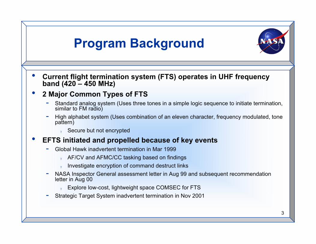
• Current flight termination system (FTS) operates in UHF frequencyband (420 – 450 MHz)
• 2 Major Common Types of FTS- Standard analog system (Uses three tones in a simple logic sequence to initiate termination,
similar to FM radio)- High alphabet system (Uses combination of an eleven character, frequency modulated, tone
pattern)γ Secure but not encrypted
• EFTS initiated and propelled because of key events- Global Hawk inadvertent termination in Mar 1999
γ AF/CV and AFMC/CC tasking based on findingsγ Investigate encryption of command destruct links
- NASA Inspector General assessment letter in Aug 99 and subsequent recommendationletter in Aug 00
γ Explore low-cost, lightweight space COMSEC for FTS- Strategic Target System inadvertent termination in Nov 2001
4
Program Background (cont.)
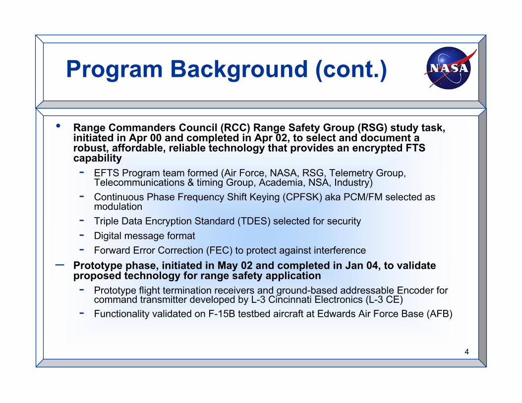
• Range Commanders Council (RCC) Range Safety Group (RSG) study task,initiated in Apr 00 and completed in Apr 02, to select and document arobust, affordable, reliable technology that provides an encrypted FTScapability- EFTS Program team formed (Air Force, NASA, RSG, Telemetry Group,
Telecommunications & timing Group, Academia, NSA, Industry)- Continuous Phase Frequency Shift Keying (CPFSK) aka PCM/FM selected as
modulation- Triple Data Encryption Standard (TDES) selected for security- Digital message format- Forward Error Correction (FEC) to protect against interference
– Prototype phase, initiated in May 02 and completed in Jan 04, to validateproposed technology for range safety application- Prototype flight termination receivers and ground-based addressable Encoder for
command transmitter developed by L-3 Cincinnati Electronics (L-3 CE)- Functionality validated on F-15B testbed aircraft at Edwards Air Force Base (AFB)

5
Program Background (cont.)
• Development of EFTS receiver and ground systems, initiatedin Jan 04 and completed in Apr 07- Receiver contracts awarded August 04 to L-3 CE to develop equipment
that meet environmental requirements for Missile, Unmanned AerialVehicle, and Space-Launch applications
- Ground Systems contract awarded August 05 to L-3 CE fordevelopment of ground system equipment (encoder, monitor, andTriple DES Unit)
• Testing-Acceptance and qualification testing on flight termination
receiver initiated in Oct 2005 and completed Apr 07γ Qualification test report accepted Aug 07
-Acceptance testing on ground equipment initiated in Dec2005 and completed in Nov 2006
6
EFTS Message Field Definitions
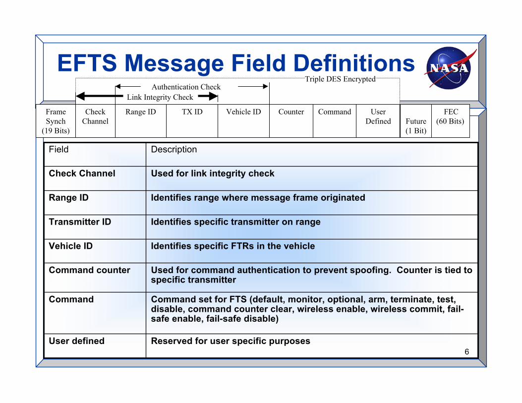
Reserved for user specific purposesUser defined
Command set for FTS (default, monitor, optional, arm, terminate, test,disable, command counter clear, wireless enable, wireless commit, fail-safe enable, fail-safe disable)
Command
Used for command authentication to prevent spoofing. Counter is tied tospecific transmitter
Command counter
Identifies specific FTRs in the vehicleVehicle ID
Identifies specific transmitter on rangeTransmitter ID
Identifies range where message frame originatedRange ID
Used for link integrity checkCheck Channel
DescriptionField
Triple DES Encrypted
Link Integrity CheckAuthentication Check
Range ID TX ID Vehicle ID CommandFrameSynch
(19 Bits)
UserDefined
FEC(60 Bits)
CounterCheckChannel Future
(1 Bit)

7
Organizations and Geography
EdwardsAFB
NASA-Dryden
EglinAFB
BourneTechnologies
L-3CincinnatiElectronics
RaytheonCompany
Test Area
TyndallAFB
NSA

8
Demonstration Purpose andGoals
• Gain experience using EFTS in an operational environment- Setup and configuration- Factory and preflight testing- Operations and monitoring- Post flight data reduction
• Provide confidence in the use of the EFTS components developed under the Central Testand Evaluation Investment Program (CTEIP)- L-3 CE Encoder, Monitor, Triple Data Encryption Standard (DES) Unit (TDU) and Flight Termination Receivers
(FTR)- National Security Agency (NSA) generated key and key loading devices- Configuration, monitoring, and recording software
• Integrate into and existing range infrastructure to demonstrate scalability of systemcomponents- Transmitter site - Button press to radiation- Monitor site - Record and monitor signal in real-time- Vehicle - Integrate into existing vehicle test package
• Provide a command controller (CC) that generates the EFTS waveform using an existingrange infrastructure- CC is interface between switch closures and EFTS encoder- CC generates unencrypted EFTS message based on switch inputs and provides to encoder- Commercial off the shelf (COTS) L-3 CE encoder generates encrypted waveform conditioned for exciter input
• Provide a report documenting the results of the demonstration

9
Potential EFTS Benefits toAMRAAM
• With Range Safety approval, the system can provide a userfeature that enables the telemetry transmitter power to beadjusted and may extend mission times
• EFTS FTRs are field programmable, minimizing required sparesand raising system availability times
• EFTS data link has a dramatically increased FTR addressingspace over current IRIG systems, and possible vehicles permission
• Designed compatibility between existing system and the EFTSsystem minimizes the required modifications to the vehicle,range, and mission operations
• Digital receivers may require less re-testing for shelf life thantone based receivers
• EFTS provides additional security against inadvertentactivation
10
Demonstration Phases
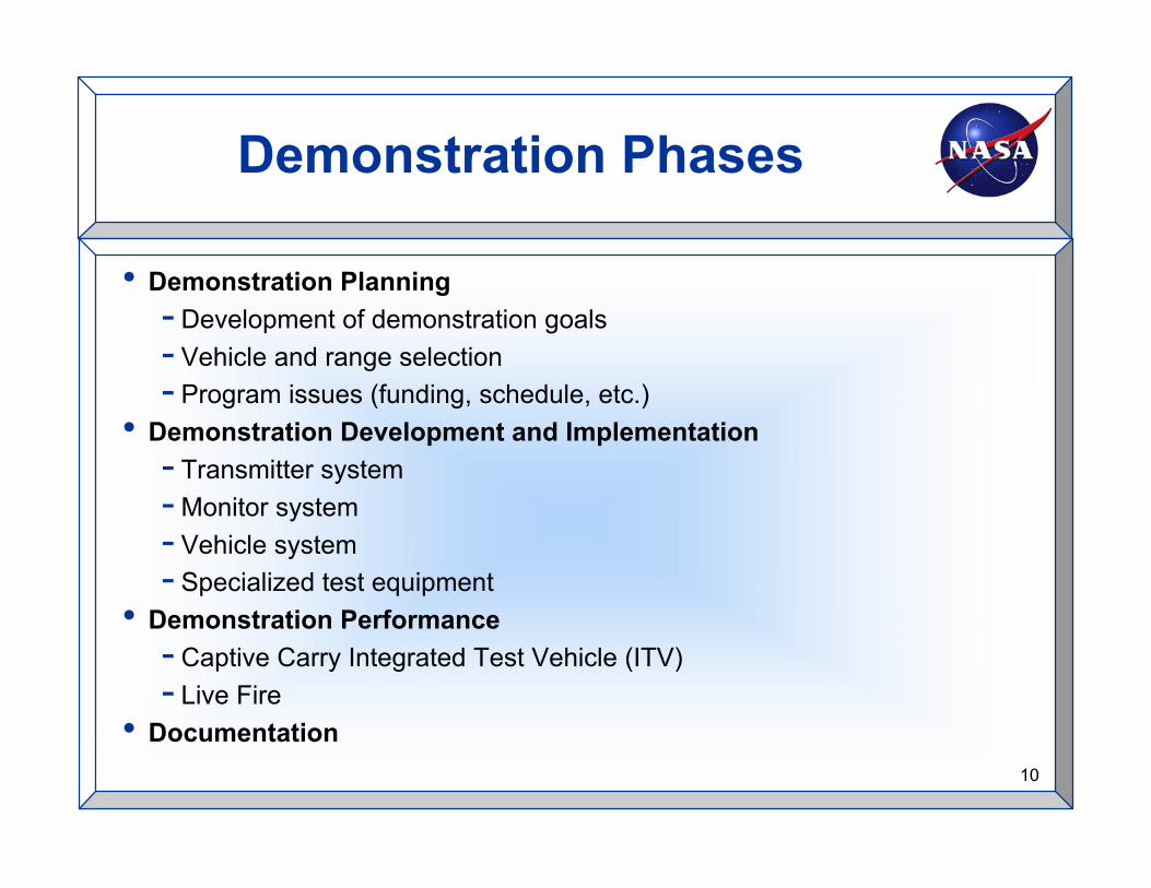
• Demonstration Planning- Development of demonstration goals- Vehicle and range selection- Program issues (funding, schedule, etc.)
• Demonstration Development and Implementation- Transmitter system- Monitor system- Vehicle system- Specialized test equipment
• Demonstration Performance- Captive Carry Integrated Test Vehicle (ITV)- Live Fire
• Documentation

11
Demonstration Planning
• Development of Demonstration Goals - EFTS Program developedobjectives and goals for selection of a demonstration site and vehicle- Primary goal of demonstration was defined to obtain operational
experience with EFTS and develop a heritage of use- Areas of operational experience include: Mission planning, pre-flight
configuration and testing (vehicle and ground systems), missionmonitoring and recording, vehicle termination, developing missionprocedures, and post mission data reduction and other post missionactivities
• Vehicle and Range Selection- Worked with AMRAAM Program Management Office (PMO) and others
to find suitable vehicles/programs to support the EFTS demonstration- AMRAAM selected because of interest in future use of EFTS by
AMRAAM program, familiarity of EFTS by range personnel at Eglin AFB,and availability of existing operational environment to support EFTStesting with available program funding
• Program Issues (Funding, Schedule, etc.)- EFTS, CTEIP, and AMRAAM Program offices met regularly to ensure
program objective would be met

12
Demonstration Development andImplementation
• Areas of Development Focus-Transmitter system - Integrate EFTS transmitter (Tx)
components into Eglin AFB transmitter system-Monitor system - Integrate EFTS monitor components into
Eglin AFB infrastructure for mission use-Vehicle system - Integrate EFTS FTR into existing AMRAAM
test package, named Non-Developmental Item-AirborneInstrumentation Unit (NDI-AIU)
-Test equipment – Baseband Output Signal Simulator (BOSS),Portable EFTS Test Set (PETS), Monitor and Record Software,Video Monitoring, Range Interface Test Set and Archival,Encoder Simulator
-Transportable system - Integrate EFTS Tx Equipment in aportable transit case
γ Simplify site-to-site relocation

13
Demonstration Development andImplementation (cont.)
• Edwards AFB Integration (Edwards, CA)- Purpose - Integrate and test all EFTS components in a lab environment
γ EFTS CC and EFTS Encoder interfaces were tested at L-3 CE prior to Tx system delivery- CC, Encoder, TDU, and DTD used with configuration software and COTS exciter
• AMRAAM Integration (Raytheon - Tucson, AZ)- Purpose - Integrate and test EFTS receiver in existing test package- Use existing AMRAAM test system augmented by EFTS BOSS for testing- Key loaded with DTD
• Eglin AFB Integration at A-3 Test Site (Fort Walton Beach, FL)- Purpose – A-3 test site has exact same system as D-3 test site- A-3 test site has RF coverage needed for testing at Eglin AFB prior to shipment to Tyndall AFB
• Eglin AFB Integration at D-3 Test Site (Cape San Blas, FL)- Purpose – D-3 test site is the operational site for mission
• Vehicle Pre-Flight Testing- Used TDU and PETS to validate test package on Flight Line 1-7 days prior to
test
14
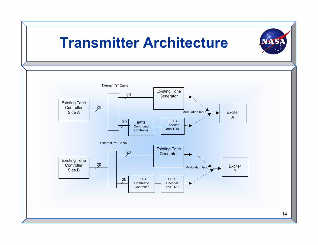
Transmitter Architecture
Modulation Input
20
Existing ToneController
Side A
Existing ToneGenerator20
20
ExciterA
20
Existing ToneController
Side B
Existing ToneGenerator
EFTSCommandController
20
ExciterB
20
External “Y” Cable
EFTSEncoderand TDU
EFTSCommandController
External “Y” Cable
EFTSEncoderand TDU
Modulation Input

15
Transmitter System
• Command Controller and “Y” Interface Cable-EFTS Program developed resources
• COTS Equipment from L-3 CE-EFTS encoder-TDU
• Developmental Software for PC applications-L-3 CE setup and monitor for encoder-L-3 CE monitor and record software-Command controller software

16
L-3 CE Encoder with TDU
17
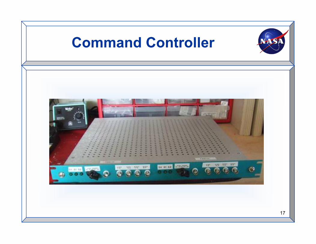
Command Controller

18
Monitor System
• Purpose - Demodulate and Decode EFTS Waveform- Real time validation of transmitted signal- Record and monitor of transmitted signal for post mission data reduction
• COTS Equipment from L-3 CE- EFTS monitor
• Developmental Software- PC based configuration- PC based display- PC based file recording of system
• Range Assets- Antennas, inter-site distribution, video recording, displays, strip charts
(for FTR TM recording)

19
L-3 CE Monitor with TDU

20
Vehicle System
• EFTS FTR is integrated into AMRAAM NDI-AIU at RaytheonCompany (Tucson, AZ)

21
Test Equipment
• Baseband Output Signal Simulator- Developed to generate the EFTS waveform, prior to the development of the EFTS
Transmitter System- Generates the EFTS waveform using TDES key, not generated by NSA- BOSS consists of a PC application, a National Instruments Data Acquisition (DAQ)
Card, a custom PWB, and cablingγ PC Applications
Generate EFTS waveform Allows setting FTR inputs (e.g. Failsafe Enable Pin) Allows monitoring of all FTR outputs (e.g. Check Output Pin) Allows configuration of FTR parameters (e.g. Frequency Range)
γ Printed Wiring Board Allows access of all FTR Signals on PWB Provides signal conditioning for DAQ Card
- Software for configuration and monitoring of FTR- Added FTR PWB to access FTR signals- Allowed factory testing with published keys
22
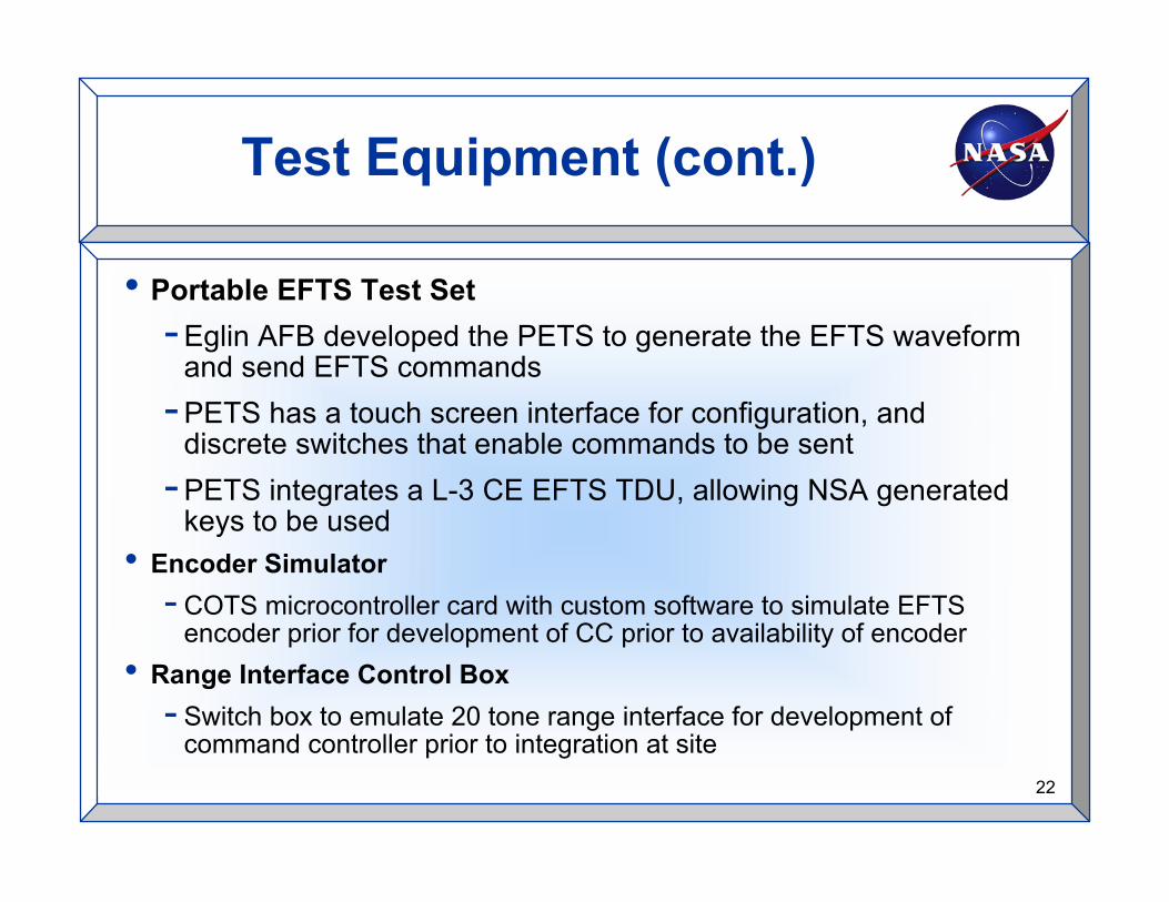
Test Equipment (cont.)
• Portable EFTS Test Set-Eglin AFB developed the PETS to generate the EFTS waveform
and send EFTS commands-PETS has a touch screen interface for configuration, and
discrete switches that enable commands to be sent- PETS integrates a L-3 CE EFTS TDU, allowing NSA generated
keys to be used• Encoder Simulator
- COTS microcontroller card with custom software to simulate EFTSencoder prior for development of CC prior to availability of encoder
• Range Interface Control Box- Switch box to emulate 20 tone range interface for development of
command controller prior to integration at site

23
Demonstration Sites
Eglin
TyndallFlight
Control
A-3 Tx
D-3 Tx and Monitor
Target
Aircraft with Missile
24
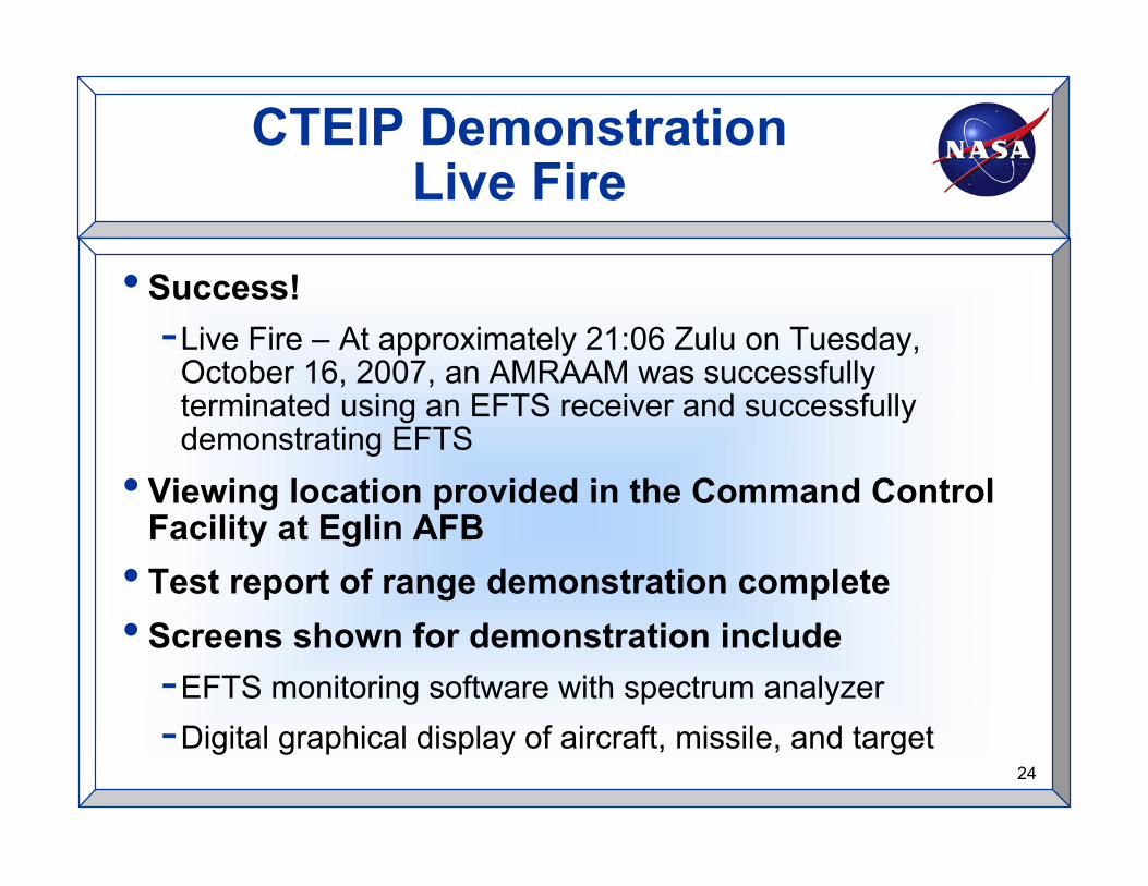
CTEIP DemonstrationLive Fire
• Success!-Live Fire – At approximately 21:06 Zulu on Tuesday,
October 16, 2007, an AMRAAM was successfullyterminated using an EFTS receiver and successfullydemonstrating EFTS
• Viewing location provided in the Command ControlFacility at Eglin AFB
• Test report of range demonstration complete• Screens shown for demonstration include
-EFTS monitoring software with spectrum analyzer-Digital graphical display of aircraft, missile, and target

25
Contacts
• Pat Feeley - CTEIP EFTS PMO• Robert Sakahara - EFTS Technical Program
Manager at NASA Dryden• David Tow - NASA Dryden• Dennis Arce - Bourne Technologies, Inc.• Steven Davies - TYBRIN Corporation

Current Upgrades for EFTS

27
2008-2010Tyndall Air Force Base - Florida
2009-2015Eastern and Western RangesSpace Command – Colorado Springs, CO
2008-2009NASA – Goddard Space Flight Center / Wallops Flight Facility
2007-2010White Sands Missile Range - NM
Equipment Purchase DatesRanges
2007-2008Naval Air Warfare Center Weapons Division - China Lake
2007-2008Naval Air Warfare Center Weapons Division - Pt. Mugu
2007-2010NASA - Dryden Flight Research Center - Edwards
2008-2010Air Force Flight Test Center - Edwards AFB
2008-2010Air Armament Center - Eglin AFB
Ranges Implementing to EFTS
28
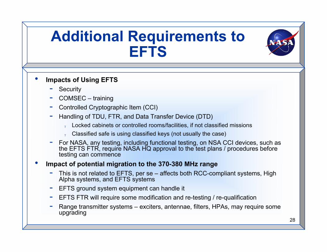
Additional Requirements toEFTS
• Impacts of Using EFTS- Security- COMSEC – training- Controlled Cryptographic Item (CCI)- Handling of TDU, FTR, and Data Transfer Device (DTD)
γ Locked cabinets or controlled rooms/facilities, if not classified missionsγ Classified safe is using classified keys (not usually the case)
- For NASA, any testing, including functional testing, on NSA CCI devices, such asthe EFTS FTR, require NASA HQ approval to the test plans / procedures beforetesting can commence
• Impact of potential migration to the 370-380 MHz range- This is not related to EFTS, per se – affects both RCC-compliant systems, High
Alpha systems, and EFTS systems- EFTS ground system equipment can handle it- EFTS FTR will require some modification and re-testing / re-qualification- Range transmitter systems – exciters, antennae, filters, HPAs, may require some
upgrading
29
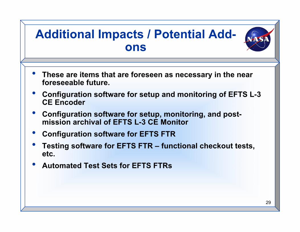
Additional Impacts / Potential Add-ons
• These are items that are foreseen as necessary in the nearforeseeable future.
• Configuration software for setup and monitoring of EFTS L-3CE Encoder
• Configuration software for setup, monitoring, and post-mission archival of EFTS L-3 CE Monitor
• Configuration software for EFTS FTR• Testing software for EFTS FTR – functional checkout tests,
etc.• Automated Test Sets for EFTS FTRs

30
Questions??