engineers mechanics- introduction for a rigid body in static equilibrium, external forces and...
TRANSCRIPT

© IIT Bombay , CE Dept, Lecture Notes for CE201 © IIT Bombay , CE Dept, Lecture Notes for CE201 1 - 1
Definitions, assumptions
• Mechanics:- Statics – body at rest under action of forces. All quantities time
independent- Dynamics – body in motion under action of forces. All quantities
time dependent
Engineers Mechanics- Introduction
A ‘particle’ idealizes a body by placing its mass at its center and neglecting its dimensions.
• Rigid Body Mechanics:Assume rigid body– no deformation, original geometry

© IIT Bombay , CE Dept, Lecture Notes for CE201 1 - 2
Introduction
• Condition for static equilibrium of a body is that resultant force and resultant couple due to all external forces are zero,
0;0 FrMR O
000000
zyx
zyxMMMFFF
• Resolving into rectangular Cartesian components leads to 6 scalar equations for static equilibrium,
• For a rigid body in static equilibrium, external forces and moments are balanced and will impart no translational or rotational motion to body.
Engineers Mechanics- Equilibrium of Rigid Bodies
© IIT Bombay , CE Dept, Lecture Notes for CE201 1 - 3
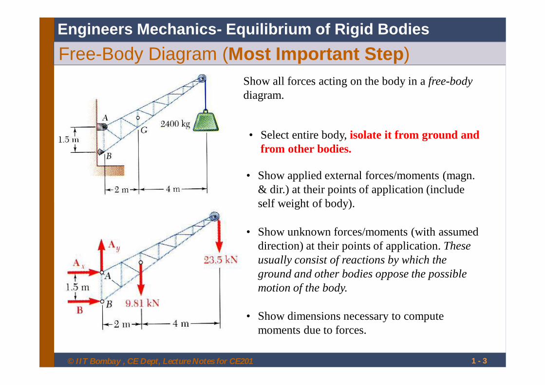
Free-Body Diagram (Most Important Step)Show all forces acting on the body in a free-bodydiagram.
• Select entire body, isolate it from ground and from other bodies.
• Show dimensions necessary to compute moments due to forces.
• Show unknown forces/moments (with assumed direction) at their points of application. These usually consist of reactions by which the ground and other bodies oppose the possible motion of the body.
• Show applied external forces/moments (magn. & dir.) at their points of application (include self weight of body).
Engineers Mechanics- Equilibrium of Rigid Bodies

© IIT Bombay , CE Dept, Lecture Notes for CE201 © IIT Bombay , CE Dept, Lecture Notes for CE201 1 - 4
Engineers Mechanics- Equilibrium of Rigid BodiesReactions from supports and connections
Supports and connections hold body in position (equilibrium) under action of externally applied forces
Body exerts force on support / connection. From Newton’s third law, support / connection exerts equal and opposite reaction force on body
The reaction force on body opposes the motion of the body.
For a 2D body, 2 translational motions and 1 rotational motion possible
For a 3D body, 3 translational motions and 3 rotational motions possible
© IIT Bombay , CE Dept, Lecture Notes for CE201 1 - 5
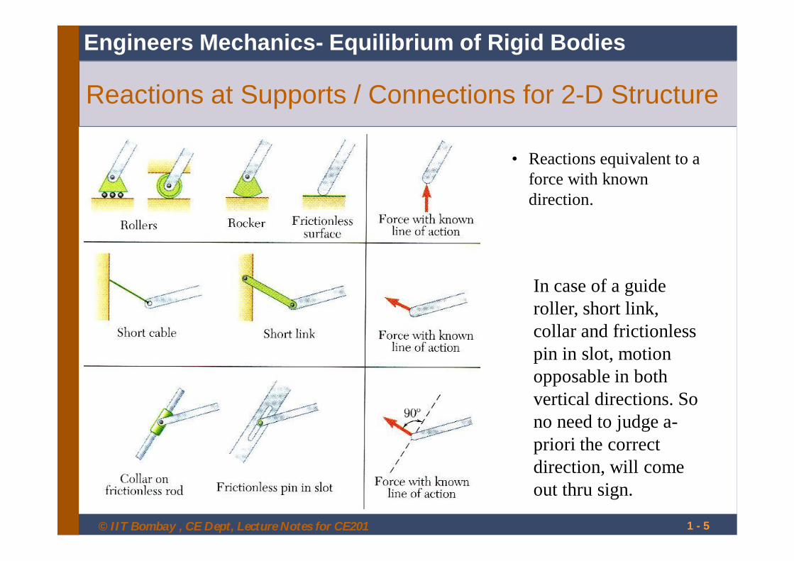
Reactions at Supports / Connections for 2-D Structure
• Reactions equivalent to a force with known direction.
Engineers Mechanics- Equilibrium of Rigid Bodies
In case of a guide roller, short link, collar and frictionless pin in slot, motion opposable in both vertical directions. So no need to judge a-priori the correct direction, will come out thru sign.

© IIT Bombay , CE Dept, Lecture Notes for CE201 1 - 6
Reactions at Supports / Connections for 2-D Structure
Engineers Mechanics- Equilibrium of Rigid Bodies
For pin or fixed support, no need to a-priori judge the correct direction (i.e., + or -). It will come out thru the sign in the result.
• Reactions equivalent to a force of unknown direction and magnitude, which is eqvt. to two forces of unknown magnitude.
Hinge support opposes movement in vertical and horizontal direction
• Reactions equivalent to a force of unknown direction and magnitude and a couple.of unknown magnitude
Fixed support opposes movement in vertical and horizontal direction as well as rotation

© IIT Bombay , CE Dept, Lecture Notes for CE201 1 - 7
2-D Equilibrium• For 2-D structure in x-y plane, with applied
forces/moments in in x-y plane, following identically satisfied
00 yxz MMF• Useful equations of equilibrium are
0)(00 Azyx MFFwhere A is any point in plane of structure.
• The 3 equations can be solved for at most 3 unknowns. Concept of Static Determinacy.
• Due to linear dependence, the 3 equations can not be augmented with additional equations, but can be replaced
0)(0)(0 BzAzx MMF
Engineers Mechanics- Equilibrium of Rigid Bodies

© IIT Bombay , CE Dept, Lecture Notes for CE201 1 - 8
Statically Indeterminate Reactions
• More unknowns than equations
• Fewer unknowns than equations, partially constrained
• Equal number unknowns and equations but improperly constrained
Engineers Mechanics- Equilibrium of Rigid Bodies

© IIT Bombay , CE Dept, Lecture Notes for CE201 1 - 9
3-D Equilibrium• For general 3-D body, six scalar equations required to
express equilibrium.
000000
zyx
zyx
MMMFFF
• Equations can be solved for at most 6 unknowns which generally are reactions.
• Scalar equations conveniently obtained from vector equations of equilibrium,
00 FrMF O
Engineers Mechanics- Equilibrium of Rigid Bodies

© IIT Bombay , CE Dept, Lecture Notes for CE201 1 - 10
Reactions at Supports / Connections for 3-D Structure
Engineers Mechanics- Equilibrium of Rigid Bodies

© IIT Bombay , CE Dept, Lecture Notes for CE201 1 - 11
Reactions at Supports / Connections for 3-D Structure
Engineers Mechanics- Equilibrium of Rigid Bodies

© IIT Bombay , CE Dept, Lecture Notes for CE201 1 - 12
Signpost of uniform density weighs 270 N, supported by ball-and-socket joint at A and by two cables.
Determine tension in each cable and reaction at A.
SOLUTION:
• Create a free-body diagram for the sign.
• Apply scalar or vector eqns of equil. to find 5 reactions/unknons.
• But 6 equil eqns? ?
Engineers Mechanics- Equilibrium of Rigid Bodies3-D Equilibrium example
0xM

© IIT Bombay , CE Dept, Lecture Notes for CE201 1 - 13
Equilibrium of Two-Force Body• Applied forces only F1 and F2 . No moments
applied.
• For equilibrium, moment of F2 about A must be zero. Thus line of action of F2 must pass through A.
• Similarly, line of action of F1 must pass through Bfor sum of moments about B to be zero.
• From above, and from sum of forces in any direction being zero, we conclude that F1 and F2 must have equal magnitude and opposite sense, and be directed along line joining their points of application.
Engineers Mechanics- Equilibrium of Rigid Bodies

© IIT Bombay , CE Dept, Lecture Notes for CE201 1 - 14
Equilibrium of Three-Force Body
• Forces acting at only 3 points.
• Assume their lines of action intersect. Moment of F1and F2 about intersection D is zero.
• But, for equilibrium, sum of moments of F1, F2, F3 ,about any point is zero. Thus moment of F3 about D is zero, i.e., line of action of F3 must pass through D.
• The lines of action of the three forces must be concurrent.
Engineers Mechanics- Equilibrium of Rigid Bodies

© IIT Bombay , CE Dept, Lecture Notes for CE201 © IIT Bombay , CE Dept, Lecture Notes for CE201 1 - 15
Man raises 10 kg joist, of length 4 m, by pulling rope.
Find tension in rope and reaction at A.
Engineers Mechanics- Equilibrium of Rigid BodiesThree-Force Body example
Free body diagram

© IIT Bombay , CE Dept, Lecture Notes for CE201 © IIT Bombay , CE Dept, Lecture Notes for CE201
Using Symmetry to convert 3D problems to 2D
• Box has 3-planes of symmetry. • Loading had only one plane of symmetry• Using symmetry and static equivalence, the problem can be converted into a 2D
problem
Engineers Mechanics- Equilibrium of Rigid Bodies

© IIT Bombay , CE Dept, Lecture Notes for CE201 © IIT Bombay , CE Dept, Lecture Notes for CE201
Example: 3D problem as 2D problemEngineers Mechanics- Equilibrium of Rigid Bodies

© IIT Bombay , CE Dept, Lecture Notes for CE201 1 - 18
Truss - Method of Joints
• Create FBD for each (member and) pin joint.
• Loading at joints only and joints are pins. So member are two force members, i.e., they possess equal and opp. forces, directed along member, at each end.
• So forces exerted by member on the pin joints at its ends are directed along member (equal and opposite to coresponding member force).
• Equilibrium of pins provide 2n equations for 2nunknowns for plane truss. For simple truss, 2n= m + r. Solve m member forces and r reactions. r = 3 for a simple truss. Simple truss is statically determinate.
Engineers Mechanics- Truss

© IIT Bombay , CE Dept, Lecture Notes for CE201 1 - 19
Special cases – zero force members, etc.• Only four members intersect at joint as two
str. lines, forces in colinear. mem’s equal.• Only 3 mem’s intersect, two of them
colinear, force in two col. mem’s equal if load aligned with third mem. Third mem. force equals load (including zero load).
• Only two members connected at unloaded joint. Forces in mem’s equal if mem’scolinear, else zero.
• Recognizing these simplifies truss analysis.
Engineers Mechanics- Truss
© IIT Bombay , CE Dept, Lecture Notes for CE201 1 - 20
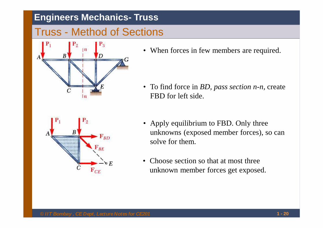
Truss - Method of Sections• When forces in few members are required.
• To find force in BD, pass section n-n, create FBD for left side.
• Apply equilibrium to FBD. Only three unknowns (exposed member forces), so can solve for them.
Engineers Mechanics- Truss
• Choose section so that at most three unknown member forces get exposed.

© IIT Bombay , CE Dept, Lecture Notes for CE201 1 - 21
Analysis of Frames
• Joints may not be only pins, loading may not be only at joints.
• At least one member multiforce member.
• FBD of complete frame used to determine unknown external forces coming from supports or connected bodies). This is external equilibrium analysis.
Engineers Mechanics- Frames
This is Rigid Frame , i.e., its internal members do not collapse if supports are removed
© IIT Bombay , CE Dept, Lecture Notes for CE201 © IIT Bombay , CE Dept, Lecture Notes for CE201 1 - 22
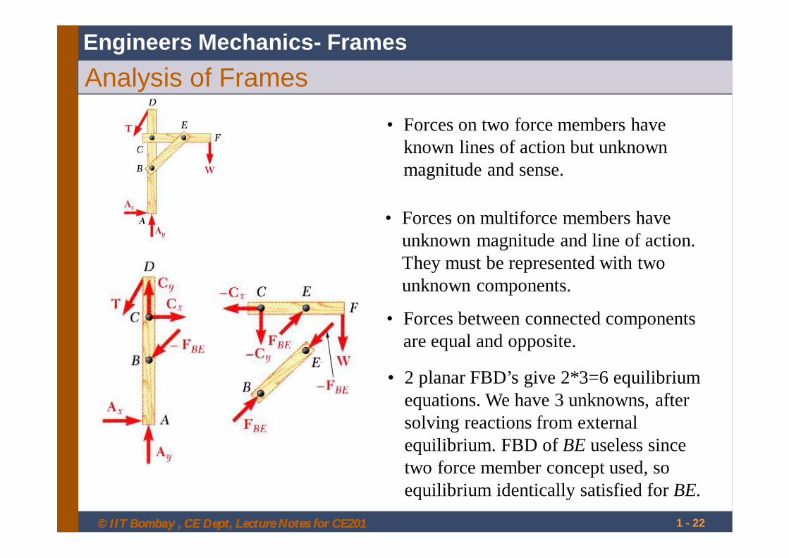
• Forces on two force members have known lines of action but unknown magnitude and sense.
• Forces on multiforce members have unknown magnitude and line of action. They must be represented with two unknown components.
Analysis of Frames
• Forces between connected components are equal and opposite.
Engineers Mechanics- Frames
• 2 planar FBD’s give 2*3=6 equilibrium equations. We have 3 unknowns, after solving reactions from external equilibrium. FBD of BE useless since two force member concept used, so equilibrium identically satisfied for BE.

© IIT Bombay , CE Dept, Lecture Notes for CE201 1 - 23
Non-rigid frames
• Some frames collapse if removed from supports. Such frames can not be treated as rigid bodies.
• External FBD shows 4 reaction components. Cannot be determined from 3 external equilibrium equations.
• Must dismember frame. Draw component FBD’s.
• 2 FBD’s, 2*3=6 equil. eqns., 6 unknown forces.
Engineers Mechanics- Frames
• Nothing special about this method. Can use it for rigid frames also.
• In previous example of rigid frame, we have 2 planar FBD’s give 2*3=6 equilibrium equations. We have 6 unknowns. FBD of BE useless since two force member concept used, so equilibrium identically satisfied for BE.