engineering track maintenance
TRANSCRIPT
ENGINEERING
TRACK
MAINTENANCE
Field Handbook
Revision: February 4, 2022
Engineering Track Maintenance Field Handbook Table of Contents
Revision: February 4, 2022 Contents-1
TABLE OF CONTENTS
1.0 ROADBED
2.0 TRACK GEOMETRY
3.0 TIES AND FASTENINGS
4.0 RAIL AND JOINTS
5.0 TURNOUTS
6.0 RIGHT OF WAY AND OTHER FACILITIES
GLOSSARY
Engineering Track Maintenance Field Handbook 1 Roadbed
Revision: September 28, 2020 Page 1
1.0 RO
AD
BE
D
1 ROADBED
1.1 Cross Section .............................................................................................................................................. 2
1.2 Drainage ..................................................................................................................................................... 2
1.2.1 General Drainage ......................................................................................................................... 2
1.2.2 Grade............................................................................................................................................ 3
1.3 Surface Drainage ........................................................................................................................................ 3
1.3.1 Ditch Construction and Maintenance ........................................................................................... 3
1.3.2 Culverts ........................................................................................................................................ 4
1.3.3 Culvert Installation ...................................................................................................................... 4
1.3.4 Culvert Identification ................................................................................................................... 5
1.3.5 Grade Crossing Drainage ............................................................................................................. 5
1.3.6 Berms and Levees ........................................................................................................................ 5
1.3.7 Erosion Control ............................................................................................................................ 5
1.4 Subsurface Drainage .................................................................................................................................. 6
1.5 Track Stability ............................................................................................................................................ 6
1.5.1 Slope Stability .............................................................................................................................. 6
1.6 Ballast......................................................................................................................................................... 6
1.6.1 Purpose ........................................................................................................................................ 6
1.6.2 Ballast Section ............................................................................................................................. 7
1.6.3 Sources and Gradation ................................................................................................................. 8
1.7 Subgrade Underlayment ............................................................................................................................. 9

1 Roadbed Engineering Track Maintenance Field Handbook
Page 2 Revision: September 28, 2020
1.1 Cross Section
The ideal roadbed section conforms with Standard Drawing Nos. 0001, 0002 and 0003.
Many historical cross sections exist due to the design techniques available when the track was constructed and thus
cannot conform exactly to Standard Drawing Nos. 0001, 0002 or 0003. The key is that these historical cross
sections be maintained to allow water to freely drain away from the track structure.
1.2 Drainage
1.2.1 General Drainage
Roadbed drainage is the most important component of good track maintenance. The railroad track structure is
designed to be permeable and allow water to freely flow through and away, it is not intended to act as a dam or
barricade for water. To achieve proper drainage that diverts water away from the track, either direct the water
parallel to and/or across the roadbed, or intercept and divert the water before it reaches the roadbed.
To provide adequate drainage, consider the following:
Maximum expected runoff from rain, melting snow, or other sources
Track and roadbed conditions that will develop during freezing temperatures
Follow these guidelines:
1. Water carrying devices can become blocked by debris which may reduce their ability to carry water.
2. Obstructions outside of the right of way can also interfere with waterflow.
3. During heavy rainfall or runoff, monitor water-carrying devices to make sure they handle the flow of water.
Report any devices that cannot handle the water flow to the Manager Track Maintenance. If devices cannot
handle the water flow the Engineering Design Department or Sr. Manager Special Projects (402-544-3672)
can assist with H&H evaluation to determine correct sizing.
4. Do not allow adjacent land owners or other parties to divert water from their property into existing water-
carrying devices or to construct such devices on the railroad right of way. Immediately report such
activities to the Manager Track Maintenance.
Engineering Track Maintenance Field Handbook 1 Roadbed
Revision: September 28, 2020 Page 3
1.0 RO
AD
BE
D
1.2.2 Grade
The slope and grade of the track structure and surrounding adjacent grade should direct water away from the track
toward natural or man-made water-carrying devices.
Follow these guidelines to ensure the correct grade:
1. Construct and maintain subgrade to a 2% cross slope when possible. Existing railroad grades on track
historically constructed may not conform to the 2% grade. They must be maintained to allow water to flow
away from the track to water carrying devices such as ditches, culverts, etc. Ditches, subsurface drains,
perforated pipe, rock drains, or other water-carrying devices should be installed and maintained at a
minimum slope of 3 inches in every 100 feet of length.
2. When water-carrying devices run parallel to the track, make sure they are sloped in a manner that will carry
water in the intended direction. Ideal slope of 3 inches every 100 feet of length should be targeted,
however, minimal slopes can still carry water.
1.3 Surface Drainage
1.3.1 Ditch Construction and Maintenance
IMPORTANT: At least 48 hours before performing work, call Union Pacific's Call Before You Dig hotline
(800-336-9193) to determine if there are any fiber optic cables or other utilities in the work area.
After the UPRR Hotline has been contacted, each State has a one-call hotline that must also be contacted at
least 48 hours before performing any work. Call the North American One Call Referral System (888-258-
0808) to obtain the appropriate state one-call number. Call the state one-call center, who will notify all utility
owners within the work area. Visit http://Call811.com to determine your states one call number.
Do not begin excavation or construction along the railroad's right-of-way until all utilities in the work area
have been located and protected by their owners.
Utilize the following guidelines when constructing and maintaining ditches:
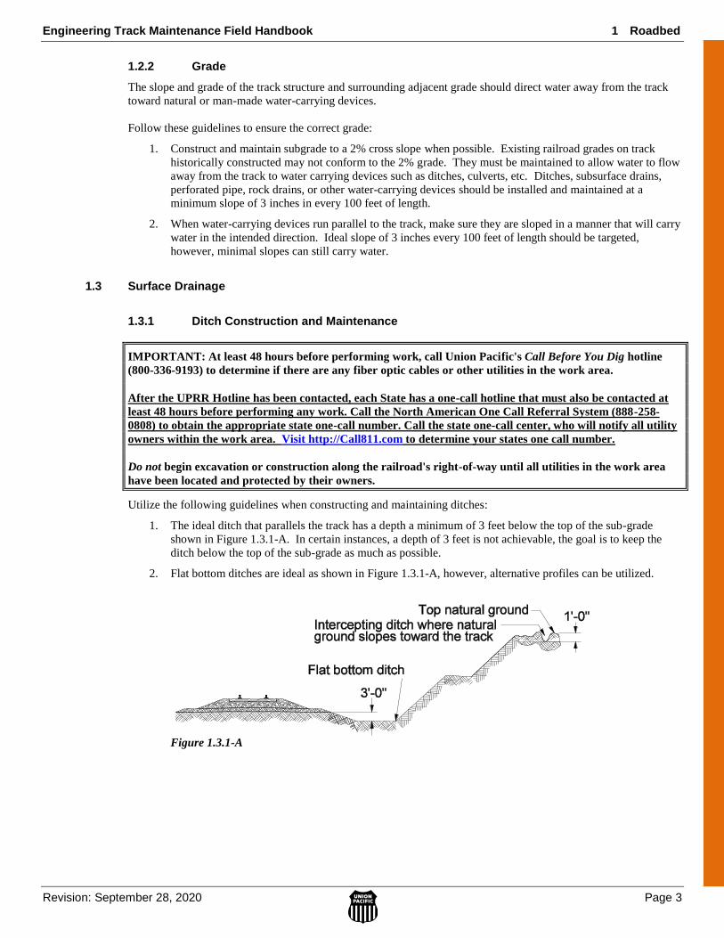
1. The ideal ditch that parallels the track has a depth a minimum of 3 feet below the top of the sub-grade
shown in Figure 1.3.1-A. In certain instances, a depth of 3 feet is not achievable, the goal is to keep the
ditch below the top of the sub-grade as much as possible.
2. Flat bottom ditches are ideal as shown in Figure 1.3.1-A, however, alternative profiles can be utilized.
Figure 1.3.1-A
1 Roadbed Engineering Track Maintenance Field Handbook
Page 4 Revision: September 28, 2020
3. Intercepting ditches can be utilized in situations where water needs to be kept at the top or middle of a
slope to keep it away from the track structure. These ditch types can help prevent erosion in certain
applications. Ideal intercepting ditches are 1 foot in depth and flat bottomed. Direct the outlet end away
from the track structure when possible.
4. Cut ditches through heavy snow wherever a sudden thaw could cause excessive runoff toward the track
structure.
5. Many historical ditch sections exist that do not conform to modern requirements/design due to clearance
concerns, bedrock depth, etc. Historical ditch sections should be maintained to allow for maximum water
flow and may not be able to be upgraded to the latest profile.
NOTE: If grading or disturbing the soil will affect 1 acre or more; construction permits are required.
Consult the Environmental Policy Guide prior to performing work to ensure that all requirements
are met. Direct questions about grading/dirt work affecting storm water run-off to the
Environmental Engineering Group.
1.3.2 Culverts
Follow these guidelines to ensure that culverts provide adequate drainage:
NOTE: Ensure the cover thickness over the top of the culvert to the bottom of the tie is at least one-half the thickness of the culvert diameter.
1. The Track Department inspects and maintains culverts less than 48 inches in diameter. For irregular
rectangular culverts, the Track Department maintains those with an entry area less than 16 square feet.
2. Inspect culverts per the following; refer to the Work Procedure Document on Culvert Inspection for
additional information.
Tier 1 Culverts
Any Culvert (Large and Small) that is within a mile (either side) of a repeat water event location.
or
A single culvert Washout location.
or
Regional AVP Maintenance designation.
Tier 2 Culverts
All other culverts that do not meet Tier 1 requirements.
1.3.3 Culvert Installation
Prior to installing a new culvert or increasing the size of a culvert, consult with the Engineering Environmental
Group and Engineering Design to determine if any permitting requirements exist and that the culvert is designed
correctly to handle the anticipated water flow. Refer to the WPD on Culvert Installation.
1. When the open cutting method of installation is used, UPRR trenching and shoring standards must be
complied with. Refer to CE Bulletin 124.0.
2. Establish flow line elevations to ensure proper drainage. Outlet elevation must be lower than inlet
elevation.
3. Bedding for pipe needs to be an engineered select material (i.e. approved road base material) and well
compacted in place.
4. If continuous length pipe cannot be used and the use of bands and/or connectors would be needed consult
the Manager Bridge Maintenance for proper material and procedures.
5. Backfill pipe evenly with a select, compactable material such as SB-2 base rock.
Engineering Track Maintenance Field Handbook 1 Roadbed
Revision: September 28, 2020 Page 5
1.0 RO
AD
BE
D
1.3.4 Culvert Identification
All culverts on main tracks, sidings or industrial leads less than 48 inches in diameter must be identified per the
following guidelines. Refer to UPRR Standard Drawing No. 0510.
1. Tie closest to the center of a culvert location to be painted blue. In locations with multiple culverts, tie
closest to the center of the culvert group is to be painted.
2. Krylon OSHA blue paint to be utilized to paint tie. Paint can be ordered in one gallon buckets in e-
procurement item number 353-1450.
3. Entire exposed top surface of the tie to be painted. Do not paint the plates or rail.
4. Upon completion of Track Program work or maintenance, ensure the culverts are properly identified.
1.3.5 Grade Crossing Drainage
Maintaining drainage around Grade Crossings is critical to their long term performance. Water trapped in the Grade
Crossing structure can lead to premature breakdown of the ties, fastening components and sub-grade. When
installing road crossings, the use of sub-grade underlayment is recommended, and drainage tile should be used if
conditions warrant or if required by state or local agencies. See the WPD on Grade Crossing Drainage for additional
information.
1.3.6 Berms and Levees
Berms or Levees can be used to divert water away from the roadbed or toward water-carrying devices in areas with
high runoff. They will be designed by a professional engineer and properly permitted.
1.3.7 Erosion Control
Erosion on fills/cuts can lead to fouling of the track or loss of stability. In addition erosion around culverts, bridges,
etc. during periods of heavy water flow can lead to long term risk. Follow these guidelines to control erosion:
1. Seed embankments or other locations graded on the right of way with native grasses.
2. Use an apron of concrete or rock to protect the outlet ends of perforated pipes that direct water onto
embankments.
3. Do not excavate material from the slopes of embankments.
4. Place rock or riprap at locations where material is being eroded and the water flow cannot be slowed or
diverted.
5. When selecting the best size of material for controlling erosion, consider the following:
The amount and force of the water the material will be exposed to.
The equipment available for handling the material after it is unloaded.
See Table 1.3.7-A for stock materials for erosion control.
Stock Materials for Erosion Control
Size Description
2 to 5 in. B stone
12 in. minus A stone
4” x 12” minus Class 1 riprap
12” x 24” minus Class 2 riprap
24” x 36” minus Class 3 riprap
36” x 36” minus Class 4 riprap
Table 1.3.7-A
1 Roadbed Engineering Track Maintenance Field Handbook
Page 6 Revision: September 28, 2020
1.4 Subsurface Drainage
Install underground drainage systems in locations where side ditches cannot be effectively maintained, such as wet
or narrow cuts, tunnels, station platforms or yard tracks.
Follow these guidelines to install devices for subsurface drainage:
1. When laying pipe as part of a subsurface drainage system, place the pipe at true grade so that the pipe outlet
will drain water away from track structure.
2. When installing catch basins, risers, or manholes that are tied to drainage systems, set them at an elevation
to adequately drain the intended area.
3. Place subsurface drainpipe at least 18 inches (where practicable) below ground level or the bottom of the
rail.
4. When placing pipe into an excavated ditch:
Line the bottom of the ditch with compacted material.
Place the pipe on top of the compacted material and center it between the ditch sidewalls.
Backfill the ditch entirely with coarse ballast and place at least 24 inches of ballast (where practicable)
on top of the pipe.
1.5 Track Stability
Water in the track structure can lead to premature breakdown of everything from the subgrade layer to the ballast
layer, and eventually the track components themselves, such as ties and rail. Even the weakest soils can perform
when well compacted and kept dry. In areas where repeated chronic geometry conditions occur it is important to
consider if water infiltration is causing the issue. It is important to look for the root cause and not resort to
repeatedly surfacing the location.
Trench drains, perforated pipe, shear keys and track injection are ways that water can be kept out of the track
structure. Refer to the WPD on Trench Drains and Shear Keys for additional information.
1.5.1 Slope Stability
In many cases the railroad is built on locations of high fill. When constructing track on fill material it is critical to
monitor and control the compaction and to keep water away from the fill when possible. On existing fill locations it
is important to monitor for signs of slope stability loss. Examples of slope stability loss include:
1. Chronic loss of cross-level or profile at a location.
2. Evidence of trapped water such as heaving/bulging on the slope.
3. Signs of movement of the slope such as leaning trees or signs.
It is important to avoid placing additional weight on the top of a slope, such as unloaded rip-rap material, to avoid
putting additional pressure on the slope. Refer to the WPD on Slope Stability for additional instructions.
See Table 1-A for rip-rap material sizing and types for slope stabilization.
1.6 Ballast
1.6.1 Purpose
Ballast serves the following purposes:
1. Uniformly transmits and distributes the load of track and railroad rolling stock to the subgrade.
2. Restrains the longitudinal, lateral, and vertical displacement of track under loads imposed by railroad
rolling stock and forces exerted by the rail.
3. Allows the track to drain quickly and prevents water from accumulating around the track structure.
Engineering Track Maintenance Field Handbook 1 Roadbed
Revision: September 28, 2020 Page 7
1.0 RO
AD
BE
D
4. Retards the growth of vegetation.
5. Reduces frost heaving of track caused by water from the subgrade.
6. Allows employees to correct irregularities in track surface and alignment.
1.6.2 Ballast Section
The ideal ballast section is shown in Standard Drawing No. 0001 for wood tie track, No. 0002 for concrete tie track
and No. 0003 for industrial track.
Follow these guidelines to establish and maintain the ballast section:
1. Maintain tie cribs with ballast to a level 1 inch below the rail base. Maintain the ballast line on an even
plane for the full length of the tie.
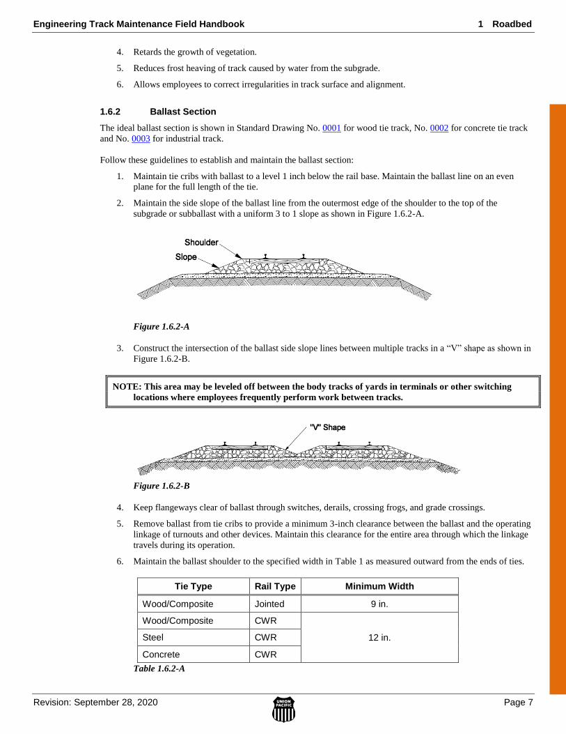
2. Maintain the side slope of the ballast line from the outermost edge of the shoulder to the top of the
subgrade or subballast with a uniform 3 to 1 slope as shown in Figure 1.6.2-A.
Figure 1.6.2-A
3. Construct the intersection of the ballast side slope lines between multiple tracks in a “V” shape as shown in
Figure 1.6.2-B.
NOTE: This area may be leveled off between the body tracks of yards in terminals or other switching
locations where employees frequently perform work between tracks.
Figure 1.6.2-B
4. Keep flangeways clear of ballast through switches, derails, crossing frogs, and grade crossings.
5. Remove ballast from tie cribs to provide a minimum 3-inch clearance between the ballast and the operating
linkage of turnouts and other devices. Maintain this clearance for the entire area through which the linkage
travels during its operation.
6. Maintain the ballast shoulder to the specified width in Table 1 as measured outward from the ends of ties.
Tie Type Rail Type Minimum Width
Wood/Composite Jointed 9 in.
Wood/Composite CWR
12 in. Steel CWR
Concrete CWR
Table 1.6.2-A
1 Roadbed Engineering Track Maintenance Field Handbook
Page 8 Revision: September 28, 2020
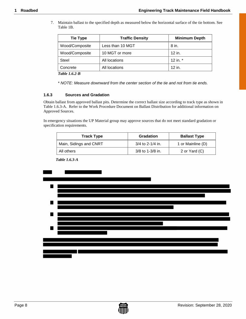
7. Maintain ballast to the specified depth as measured below the horizontal surface of the tie bottom. See
Table 1B.
Tie Type Traffic Density Minimum Depth
Wood/Composite Less than 10 MGT 8 in.
Wood/Composite 10 MGT or more 12 in.
Steel All locations 12 in. *
Concrete All locations 12 in.
Table 1.6.2-B
* NOTE: Measure downward from the center section of the tie and not from tie ends.
1.6.3 Sources and Gradation
Obtain ballast from approved ballast pits. Determine the correct ballast size according to track type as shown in
Table 1.6.3-A. Refer to the Work Procedure Document on Ballast Distribution for additional information on
Approved Sources.
In emergency situations the UP Material group may approve sources that do not meet standard gradation or
specification requirements.
Track Type Gradation Ballast Type
Main, Sidings and CNRT 3/4 to 2-1/4 in. 1 or Mainline (D)
All others 3/8 to 1-3/8 in. 2 or Yard (C)
Table 1.6.3-A

Engineering Track Maintenance Field Handbook 1 Roadbed
Revision: September 28, 2020 Page 9
1.0 RO
AD
BE
D
1.7 Subgrade Underlayment
Subgrade underlayment is an effective way to increase the strength of the track structure. It is primarily utilized in
areas where the sub-grade layer is weak or requires additional reinforcement due to high loading. Areas requiring
additional reinforcement include but are not restricted to:
1. Track Transitions
2. Road Crossings
3. Railroad Crossing Diamonds
4. Turnouts
5. Areas with historically poor sub-grade performance (chronic slow order locations)
Union Pacific utilizes two primary methods for sub-grade underlayment, Asphalt and Geo-Web/Grid. Both perform
very similarly. See the WPD on Sub-grade Underlayment for additional information.

Engineering Track Maintenance Field Handbook 2 Track Geometry
Revision: September 28, 2020 Page 1
2 Track Geometry
2.1.1 Determine Designated Rail ........................................................................................................ 3
2.2 Track Alignment ...................................................................................................................................... 3
2.2.1 Designated Line Rail for Curved Track ..................................................................................... 4
2.2.2 Designated Line Rail for Tangent Track .................................................................................... 4
2.2.3 Designated Line Rails for Turnouts and Crossovers .................................................................. 4
2.2.4 Measuring Alignment ................................................................................................................ 5
2.2.6 Line Ordinates in Turnouts and Crossovers ............................................................................... 7
A. Line Ordinates Behind Frog ............................................................................................... 7
2.2.7 Six Axle Restrictions – Maximum Curve Degree ...................................................................... 8
2.3 Track Gauge ............................................................................................................................................. 8
2.3.1 Designated Gauge Rail .............................................................................................................. 8
2.3.2 Standard Gauge .......................................................................................................................... 8
2.3.3 Measuring Gauge ....................................................................................................................... 8
2.4 Clearances .............................................................................................................................................. 12
2.4.1 Measuring Track Centers ......................................................................................................... 12
2.4.2 Minimum Track Centers .......................................................................................................... 12
2.4.3 Track Centers in Crossover Switches ...................................................................................... 14
2.4.4 Minimum Clearances ............................................................................................................... 15
2.4.5 Allowable Superelevation in Adjacent Tracks ......................................................................... 16
2.5 Grade ...................................................................................................................................................... 16
2.5.1 Designated Grade Rail ............................................................................................................. 16
2.5.2 Grade Stakes ............................................................................................................................ 16
2.5.3 Multiple Track Grade Crossings .............................................................................................. 16
2.5.4 Turnouts and Crossovers .......................................................................................................... 17
2.5.5 Vertical Curves ........................................................................................................................ 17
2.6.5 Track Surface Limits................................................................................................................ 22
2.6.6 Spirals ...................................................................................................................................... 23
2.6.7 Superelevation ......................................................................................................................... 24
2 Track Geometry Engineering Track Maintenance Field Handbook
Page 2 Revision: September 28, 2020
2.9 Surveying and Marking Curves .............................................................................................................. 34

Engineering Track Maintenance Field Handbook 2 Track Geometry
Revision: September 28, 2020 Page 3
2.1.1 Determine Designated Rail
When reading geometry or detector car reports and trying to determine which rail is the right rail and which
rail is the left rail, position yourself with your back to the lower MP. While facing the higher MP, the rail on
your right is the right rail and on your left is the left rail.
2.2 Track Alignment
Track alignment consists of tangent segments of track connected by curves. One rail of each track is
designated as the line rail.
For instructions on restoring track alignment to standard, refer to the WPD on Restoring Track to Standard.

2 Track Geometry Engineering Track Maintenance Field Handbook
Page 4 Revision: September 28, 2020
2.2.1 Designated Line Rail for Curved Track
The outer or high rail of curves is the line rail for referencing alignment.
2.2.2 Designated Line Rail for Tangent Track
Designate the line rail for referencing alignment on tangent track as follows:
Single Main Track—Use the north rail of east/west tracks and the west rail of north/south tracks.
Two Main Tracks—Use the outside rail of each track.
Three Main Tracks—Use the outside rail of the outer tracks. Use the north rail of east/west tracks
and the west rail of north/south tracks as the line rail for referencing alignment on the center track.
Four Main Tracks—Use the outside rail of the outer tracks. Use the inside rail of the inner tracks as
the line rail for referencing alignment on the center tracks.
All Other Applications—Use the most practical line rail. Use this same rail throughout the tangent
segment.
When lining tangent track between two curves of the same direction that are less than 1/4 mile apart, use the
same line reference rail.
When lining into a fixed object that is less than 1/4 mile from the curve, use the same line reference rail as
used in a curve.
NOTE: Examples of fixed objects are open deck bridges, crossing frogs, or other immovable objects.
2.2.3 Designated Line Rails for Turnouts and Crossovers
Use the straight side of turnouts as the designated line rail for referencing alignment through the straight side
of switches when turnouts exist entirely on tangent track as shown in Figure 2.2.3-A.
Figure 2.2.3-A
When any portion of a turnout is located on a curve, use the high or outer rail of the curve as the designated
line rail as shown in Figure 2.2.3-B.
Figure 2.2.3-B
Engineering Track Maintenance Field Handbook 2 Track Geometry
Revision: September 28, 2020 Page 5
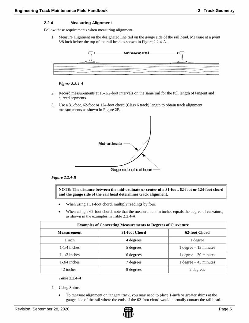
2.2.4 Measuring Alignment
Follow these requirements when measuring alignment:
1. Measure alignment on the designated line rail on the gauge side of the rail head. Measure at a point
5/8 inch below the top of the rail head as shown in Figure 2.2.4-A.
Figure 2.2.4-A
2. Record measurements at 15-1/2-foot intervals on the same rail for the full length of tangent and
curved segments.
3. Use a 31-foot, 62-foot or 124-foot chord (Class 6 track) length to obtain track alignment
measurements as shown in Figure 2B.
Figure 2.2.4-B
NOTE: The distance between the mid-ordinate or center of a 31-foot, 62-foot or 124-foot chord
and the gauge side of the rail head determines track alignment.
When using a 31-foot chord, multiply readings by four.
When using a 62-foot chord, note that the measurement in inches equals the degree of curvature,
as shown in the examples in Table 2.2.4-A.
Examples of Converting Measurements to Degrees of Curvature
Measurement 31-foot Chord 62-foot Chord
1 inch 4 degrees 1 degree
1-1/4 inches 5 degrees 1 degree – 15 minutes
1-1/2 inches 6 degrees 1 degree – 30 minutes
1-3/4 inches 7 degrees 1 degree – 45 minutes
2 inches 8 degrees 2 degrees
Table 2.2.4-A
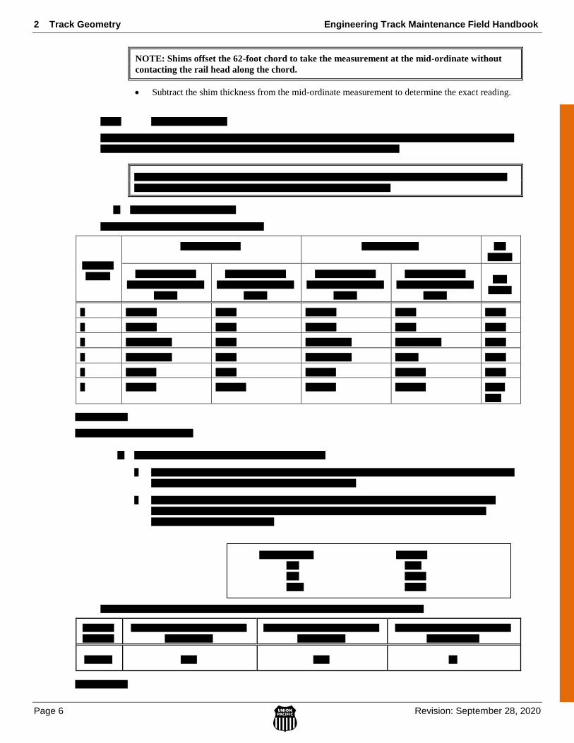
4. Using Shims
To measure alignment on tangent track, you may need to place 1-inch or greater shims at the
gauge side of the rail where the ends of the 62-foot chord would normally contact the rail head.
2 Track Geometry Engineering Track Maintenance Field Handbook
Page 6 Revision: September 28, 2020
NOTE: Shims offset the 62-foot chord to take the measurement at the mid-ordinate without
contacting the rail head along the chord.
Subtract the shim thickness from the mid-ordinate measurement to determine the exact reading.

Engineering Track Maintenance Field Handbook 2 Track Geometry
Revision: September 28, 2020 Page 7
2.2.6 Line Ordinates in Turnouts and Crossovers
The designated line rail for referencing alignment through the turnout side of switches is the turnout side
closure rail. The closure rail connects the switch point to the frog and continues from the heel of the frog
through the last long switch tie.
Follow these requirements when establishing alignment in turnouts and crossovers:
1. To establish alignment through turnout side of switches through the last long switch tie, use line
ordinates provided in the Engineering Track Standards book, Sections 5000–5099, Turnouts.
NOTE: Line ordinates denote the specific spread distance between gauge lines of curved
closure rails and adjacent rails on the straight side of turnouts. The spread distance establishes
the proper alignment for the turnout side of switches.
2. Establish alignment for the turnout side of switches not having published ordinates as follows:
a. Align the straight side of the turnout to the desired alignment.
b. Stretch a string between the heel of the switch and the toe of the frog along the gauge line.
c. Measure the overall distance and divide into four equal parts.
d. Offset the center ordinate at a right angle to the string 6 inches and spike in place.
e. Offset each quarter ordinate at a right angle to the string 4-1/2 inches and spike in place as
shown in Figure 2.2.6-A.
Figure 2.2.6-A
A. Line Ordinates Behind Frog
Line ordinates behind the frog spread apart over a given distance at a rate determined by the frog size. See
Table 2.2.6-A.
If frog size is… The spread increases
1 foot every…
7 7 feet
8 8 feet
8.5 8.5 feet
9 9 feet
10 10 feet
11 11 feet
14 14 feet
15 15 feet
20 20 feet
24 24 feet
30 30 feet
Table 2.2.6-A
2 Track Geometry Engineering Track Maintenance Field Handbook
Page 8 Revision: September 28, 2020
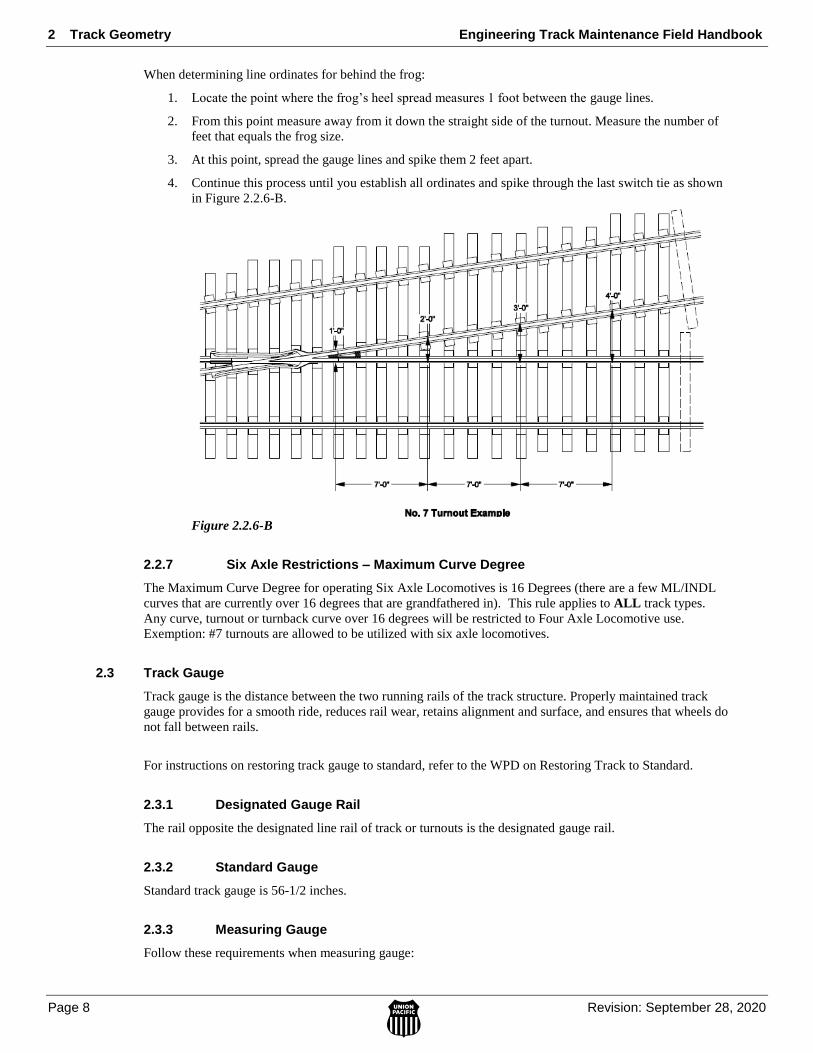
When determining line ordinates for behind the frog:
1. Locate the point where the frog’s heel spread measures 1 foot between the gauge lines.
2. From this point measure away from it down the straight side of the turnout. Measure the number of
feet that equals the frog size.
3. At this point, spread the gauge lines and spike them 2 feet apart.
4. Continue this process until you establish all ordinates and spike through the last switch tie as shown
in Figure 2.2.6-B.
Figure 2.2.6-B
2.2.7 Six Axle Restrictions – Maximum Curve Degree
The Maximum Curve Degree for operating Six Axle Locomotives is 16 Degrees (there are a few ML/INDL
curves that are currently over 16 degrees that are grandfathered in). This rule applies to ALL track types.
Any curve, turnout or turnback curve over 16 degrees will be restricted to Four Axle Locomotive use.
Exemption: #7 turnouts are allowed to be utilized with six axle locomotives.
2.3 Track Gauge
Track gauge is the distance between the two running rails of the track structure. Properly maintained track
gauge provides for a smooth ride, reduces rail wear, retains alignment and surface, and ensures that wheels do
not fall between rails.
For instructions on restoring track gauge to standard, refer to the WPD on Restoring Track to Standard.
2.3.1 Designated Gauge Rail
The rail opposite the designated line rail of track or turnouts is the designated gauge rail.
2.3.2 Standard Gauge
Standard track gauge is 56-1/2 inches.
2.3.3 Measuring Gauge
Follow these requirements when measuring gauge:
Engineering Track Maintenance Field Handbook 2 Track Geometry
Revision: September 28, 2020 Page 9
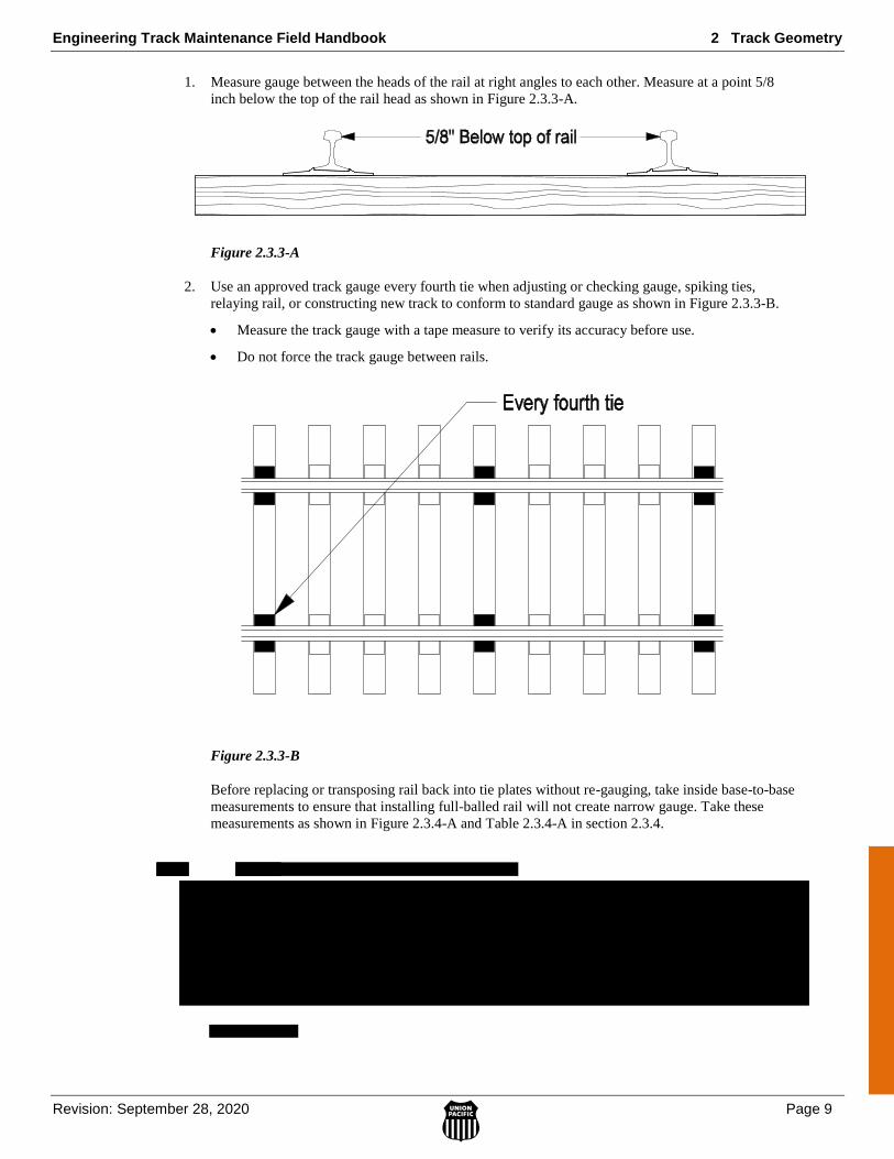
1. Measure gauge between the heads of the rail at right angles to each other. Measure at a point 5/8
inch below the top of the rail head as shown in Figure 2.3.3-A.
Figure 2.3.3-A
2. Use an approved track gauge every fourth tie when adjusting or checking gauge, spiking ties,
relaying rail, or constructing new track to conform to standard gauge as shown in Figure 2.3.3-B.
Measure the track gauge with a tape measure to verify its accuracy before use.
Do not force the track gauge between rails.
Figure 2.3.3-B
Before replacing or transposing rail back into tie plates without re-gauging, take inside base-to-base
measurements to ensure that installing full-balled rail will not create narrow gauge. Take these
measurements as shown in Figure 2.3.4-A and Table 2.3.4-A in section 2.3.4.
2 Track Geometry Engineering Track Maintenance Field Handbook
Page 10 Revision: September 28, 2020
Engineering Track Maintenance Field Handbook 2 Track Geometry
Revision: September 28, 2020 Page 11
2 Track Geometry Engineering Track Maintenance Field Handbook
Page 12 Revision: September 28, 2020
2.4 Clearances
Maintain adequate spacing between tracks to enable trains to safely pass or meet rolling stock on adjacent
tracks. Maintain sufficient horizontal and vertical clearance to enable trains to clear wayside structures and
facilities.
Reference Standard Drawing No. 0038 for Standard Minimum Operating Clearances.
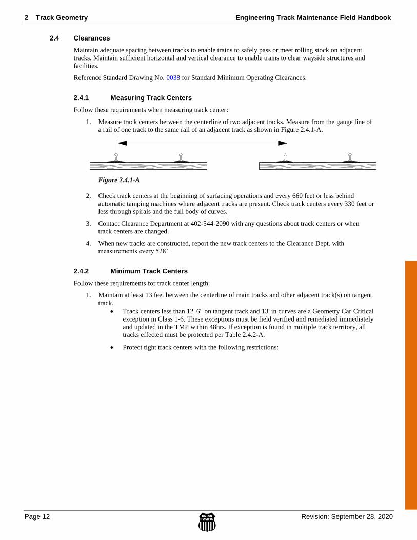
2.4.1 Measuring Track Centers
Follow these requirements when measuring track center:
1. Measure track centers between the centerline of two adjacent tracks. Measure from the gauge line of
a rail of one track to the same rail of an adjacent track as shown in Figure 2.4.1-A.
Figure 2.4.1-A
2. Check track centers at the beginning of surfacing operations and every 660 feet or less behind
automatic tamping machines where adjacent tracks are present. Check track centers every 330 feet or
less through spirals and the full body of curves.
3. Contact Clearance Department at 402-544-2090 with any questions about track centers or when
track centers are changed.
4. When new tracks are constructed, report the new track centers to the Clearance Dept. with
measurements every 528’.
2.4.2 Minimum Track Centers
Follow these requirements for track center length:
1. Maintain at least 13 feet between the centerline of main tracks and other adjacent track(s) on tangent
track.
Track centers less than 12' 6" on tangent track and 13' in curves are a Geometry Car Critical
exception in Class 1-6. These exceptions must be field verified and remediated immediately
and updated in the TMP within 48hrs. If exception is found in multiple track territory, all
tracks effected must be protected per Table 2.4.2-A.
Protect tight track centers with the following restrictions:
Engineering Track Maintenance Field Handbook 2 Track Geometry
Revision: September 28, 2020 Page 13
10 MPH 25 MPH
Degree of curve Track Centers less than Track Centers less than
0 12' 0" 12- 6"
1 12' 1-3/8" 12' 7-3/8"
2 12' 2-3/4" 12' 8-3/4"
3 12' 4-1/8" 12' 10-1/8"
4 12' 6" 12' 11-1/2"
5 12' 6-7/8" 13' 0-7/8"
6 12' 8-1/4" 13' 2-1/4"
7 12' 9-5/8" 13' 3-5/8"
8 12' 11" 13' 5"
9 13' 0-3/8" 13' 6-3/8"
10 13' 1-3/4" 13' 7-3/4"
11 13' 3-1/8" 13' 9-1/8"
12 13' 4-1/2" 13' 10-1/2"
13 13' 5-7/8" 13' 11-3/4"
14 13' 7-1/4" 14' 1-1/4"
15 13' 8-5/8" 14' 2-5/8"
16 13' 10" 14' 4"
Table 2.4.2-A
2. Maintain at least 12 feet 6 inches between the centerline of other than main tracks.
3. Maintain track centers in curves of parallel tracks to allow for car tilt and overhang due to curvature.
Maintain track centers through the entire length of the curve and for 80 feet beyond the curve.
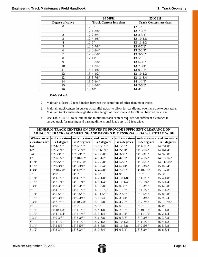
4. Use Table 2.4.2-B to determine the minimum track centers required for sufficient clearance in
curved track for meeting and passing dimensional loads up to 12 feet wide.
MINIMUM TRACK CENTERS ON CURVES TO PROVIDE SUFFICIENT CLEARANCE ON
ADJACENT TRACKS FOR MEETING AND PASSING DIMENSIONAL LOADS UP TO 12’ WIDE
Where curve
elevations are
and curvature
is 1 degree
and curvature
is 2 degrees
and curvature
is 3 degrees
and curvature
is 4 degrees
and curvature
is 5 degrees
and curvature
is 6 degrees
1/4" 13' 4-1/8" 13' 7-1/8" 13' 10-1/8" 14' 1-1/8" 14' 4-1/8" 14' 7-1/8"
1/2" 13' 5-1/4" 13' 8-1/4" 13' 11-1/4" 14' 2-1/4" 14' 5-1/4" 14' 8-1/4"
3/4" 13' 6-3/8" 13' 9-3/8" 14' 0-3/8" 14' 3-3/8" 14' 6-3/8" 14' 9-3/8"
1” 13' 7-1/2" 13' 10-1/2" 14' 1-1/2" 14' 4-1/2" 14' 7-1/2" 14' 10-1/2"
1 1/4" 13' 8-5/8" 13' 11-5/8" 14' 2-5/8" 14' 5-5/8" 14' 8-5/8" 14' 11-5/8"
1 1/2" 13' 9-3/4" 14' 0-3/4" 14' 3-3/4" 14' 6-3/4" 14' 9-3/4" 15' 0-3/4"
1 3/4" 13' 10-7/8" 14' 1-7/8" 14' 4-7/8" 14' 7-7/8" 14' 10-7/8" 15' 1-7/8"
2” 14' 0" 14' 3" 14' 6" 14' 9" 15' 0" 15' 3"
2 1/4" 14' 1-1/8" 14' 4-1/8" 14' 7-1/8" 14' 10-1/8" 15' 1-1/8" 15' 4-1/8"
2 1/2" 14' 2-1/4" 14' 5-1/4" 14' 8-1/4" 14' 11-1/4" 15' 2-1/4" 15' 5-1/4"
2 3/4" 14' 3-3/8" 14' 6-3/8" 14' 9-3/8" 15' 0-3/8" 15' 3-3/8" 15' 6-3/8"
3” 14' 4-1/2" 14' 7-1/2" 14' 10-1/2" 15' 1-1/2" 15' 4-1/2" 15' 7-1/2"
3 1/4" 14' 5-5/8" 14' 8-5/8" 14' 11-5/8" 15' 2-5/8" 15' 5-5/8" 15' 8-5/8"
3 1/2" 14' 6-3/4" 14' 9-3/4" 15' 0-3/4" 15' 3-3/4" 15' 6-3/4" 15' 9-3/4"
3 3/4" 14' 7-7/8" 14' 10-7/8" 15' 1-7/8" 15' 4-7/8" 15' 7-7/8" 15' 10-7/8"
4” 14' 9" 15' 0" 15' 3" 15' 6" 15' 9" 16' 0"
4 1/4" 14' 10-1/8" 15' 1-1/8" 15' 4-1/8" 15' 7-1/8" 15' 10-1/8" 16' 1-1/8"
4 1/2" 14' 11-1/4" 15' 2-1/4" 15' 5-1/4" 15' 8-1/4" 15' 11-1/4" 16' 2-1/4"
4 3/4" 15' 0-3/8" 15' 3-3/8" 15' 6-3/8" 15' 9-3/8" 16' 0-3/8" 16' 3-3/8"
5” 15' 1-1/2" 15' 4-1/2" 15' 7-1/2" 15' 10-1/2" 16' 1-1/2" 16' 4-1/2"
5 1/4" 15' 2-5/8" 15' 5-5/8" 15' 8-5/8" 15' 11-5/8" 16' 2-5/8" 16' 5-5/8"
5 1/2" 15' 3-3/4" 15' 6-3/4" 15' 9-3/4" 16' 0-3/4" 16' 3-3/4" 16' 6-3/4"
2 Track Geometry Engineering Track Maintenance Field Handbook
Page 14 Revision: September 28, 2020
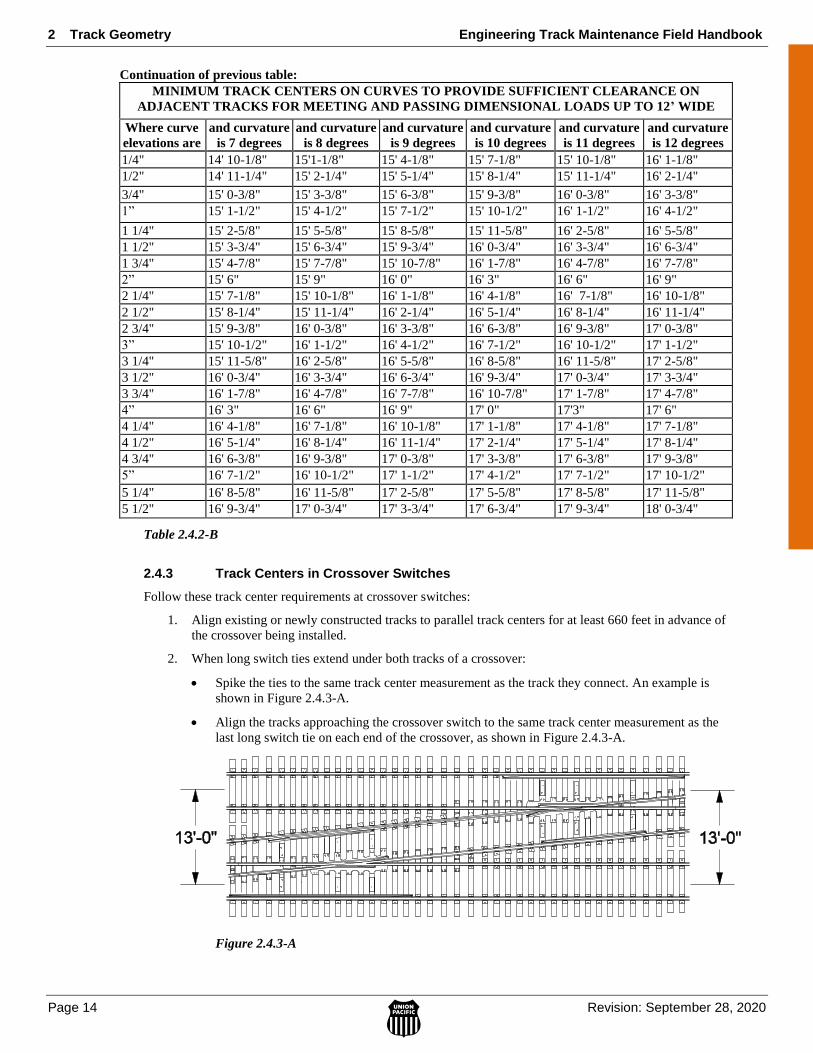
Continuation of previous table:
MINIMUM TRACK CENTERS ON CURVES TO PROVIDE SUFFICIENT CLEARANCE ON
ADJACENT TRACKS FOR MEETING AND PASSING DIMENSIONAL LOADS UP TO 12’ WIDE
Where curve
elevations are
and curvature
is 7 degrees
and curvature
is 8 degrees
and curvature
is 9 degrees
and curvature
is 10 degrees
and curvature
is 11 degrees
and curvature
is 12 degrees
1/4" 14' 10-1/8" 15'1-1/8" 15' 4-1/8" 15' 7-1/8" 15' 10-1/8" 16' 1-1/8"
1/2" 14' 11-1/4" 15' 2-1/4" 15' 5-1/4" 15' 8-1/4" 15' 11-1/4" 16' 2-1/4"
3/4" 15' 0-3/8" 15' 3-3/8" 15' 6-3/8" 15' 9-3/8" 16' 0-3/8" 16' 3-3/8"
1” 15' 1-1/2" 15' 4-1/2" 15' 7-1/2" 15' 10-1/2" 16' 1-1/2" 16' 4-1/2"
1 1/4" 15' 2-5/8" 15' 5-5/8" 15' 8-5/8" 15' 11-5/8" 16' 2-5/8" 16' 5-5/8"
1 1/2" 15' 3-3/4" 15' 6-3/4" 15' 9-3/4" 16' 0-3/4" 16' 3-3/4" 16' 6-3/4"
1 3/4" 15' 4-7/8" 15' 7-7/8" 15' 10-7/8" 16' 1-7/8" 16' 4-7/8" 16' 7-7/8"
2” 15' 6" 15' 9" 16' 0" 16' 3" 16' 6" 16' 9"
2 1/4" 15' 7-1/8" 15' 10-1/8" 16' 1-1/8" 16' 4-1/8" 16' 7-1/8" 16' 10-1/8"
2 1/2" 15' 8-1/4" 15' 11-1/4" 16' 2-1/4" 16' 5-1/4" 16' 8-1/4" 16' 11-1/4"
2 3/4" 15' 9-3/8" 16' 0-3/8" 16' 3-3/8" 16' 6-3/8" 16' 9-3/8" 17' 0-3/8"
3” 15' 10-1/2" 16' 1-1/2" 16' 4-1/2" 16' 7-1/2" 16' 10-1/2" 17' 1-1/2"
3 1/4" 15' 11-5/8" 16' 2-5/8" 16' 5-5/8" 16' 8-5/8" 16' 11-5/8" 17' 2-5/8"
3 1/2" 16' 0-3/4" 16' 3-3/4" 16' 6-3/4" 16' 9-3/4" 17' 0-3/4" 17' 3-3/4"
3 3/4" 16' 1-7/8" 16' 4-7/8" 16' 7-7/8" 16' 10-7/8" 17' 1-7/8" 17' 4-7/8"
4” 16' 3" 16' 6" 16' 9" 17' 0" 17'3" 17' 6"
4 1/4" 16' 4-1/8" 16' 7-1/8" 16' 10-1/8" 17' 1-1/8" 17' 4-1/8" 17' 7-1/8"
4 1/2" 16' 5-1/4" 16' 8-1/4" 16' 11-1/4" 17' 2-1/4" 17' 5-1/4" 17' 8-1/4"
4 3/4" 16' 6-3/8" 16' 9-3/8" 17' 0-3/8" 17' 3-3/8" 17' 6-3/8" 17' 9-3/8"
5” 16' 7-1/2" 16' 10-1/2" 17' 1-1/2" 17' 4-1/2" 17' 7-1/2" 17' 10-1/2"
5 1/4" 16' 8-5/8" 16' 11-5/8" 17' 2-5/8" 17' 5-5/8" 17' 8-5/8" 17' 11-5/8"
5 1/2" 16' 9-3/4" 17' 0-3/4" 17' 3-3/4" 17' 6-3/4" 17' 9-3/4" 18' 0-3/4"
Table 2.4.2-B
2.4.3 Track Centers in Crossover Switches
Follow these track center requirements at crossover switches:
1. Align existing or newly constructed tracks to parallel track centers for at least 660 feet in advance of
the crossover being installed.
2. When long switch ties extend under both tracks of a crossover:
Spike the ties to the same track center measurement as the track they connect. An example is
shown in Figure 2.4.3-A.
Align the tracks approaching the crossover switch to the same track center measurement as the
last long switch tie on each end of the crossover, as shown in Figure 2.4.3-A.
Figure 2.4.3-A

Engineering Track Maintenance Field Handbook 2 Track Geometry
Revision: September 28, 2020 Page 15
2.4.4 Minimum Clearances
Maintain horizontal and vertical clearances according to Standard Drawing No. 0038 and follow these
requirements:
1. Maintain appliances not shown on this drawing to a minimum clearance of 9 feet from the centerline
of the track and at least 23’4” feet above the top of the rail.
2. Place top-of-rail markers at all structures with 23 feet or less of overhead clearance. Place markers
according to Standard Drawing Nos. 0540 and 0541.
3. Where overhead and lateral obstructions are present, such as overpasses, tunnels, bridges, rock cuts,
slide fences, platforms etc., minimize track raises and never raise the track above the top of rail
markers or alter alignment from stakes.
4. Where markers indicate clearances are close, perform spot surfacing manually.
5. Before raising track above the top-of-rail marker, or aligning track that may create clearance
problems, or to report a track shift contact the Clearance Dept. at 402-544-2090.
6. If no top of rail marker is present contact Clearance Dept. prior to raising track.
7. Before the temporary installation of falsework, such as construction scaffolding, that will reduce
clearances, the Clearance Dept. must be notified at 402-544-2090. The Clearance Dept. must then
protect temporary clearance reduction by recording the falsework modification in the computerized
clearance system. Contact the Clearance Dept. when the temporary falsework clearance restriction
has been removed.
NOTE: For Clearance information please reference the Clearance Maps and Structures Site
(MyUP- >Maps>Clearance Maps and Structures.)
Clearance recommendations:
These standards will apply to all oversized loads except for double stack containers and apply to clearance car
operations.
Clearance Condition Remediation
Protect overhead and side clearances
6” or greater clearance Unrestricted
Less than 6” to 4” clearance Maximum 25 MPH
Less than 4” to 2 ½” clearance Maximum 10 MPH
Less than 2 ½” clearance Clearance Team will determine remedial action
Protect overhead clearances for double stack containers
4” or greater clearance Unrestricted
Less than 4” to 2 ½” clearance Maximum 25 MPH
Less than 2 ½” clearance Clearance Team will determine remedial action
Table 2.4.4-A
Process Summary:
1. If found by Clearance Car the Chief of the Car will immediately notify MTM/DTM, by email and phone,
to issue order. A TMP exception will be written.
An automated notification will go to the CE/GD of the Region providing location, restriction and Form A
impact.
2. If found by the EC Car the EC Car will stop and verify. If verified the MTM/DTM will immediately
issue restriction. A TMP exception will be written.
An automated notification will go to the CE/GD of the Region providing location, restriction and Form A
impact.
Clearance Questions Contact Clearance Department 402-544-2090
2 Track Geometry Engineering Track Maintenance Field Handbook
Page 16 Revision: September 28, 2020
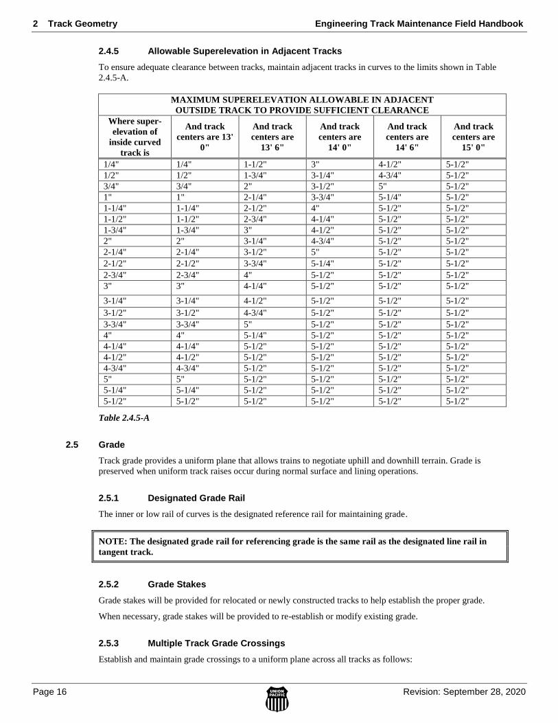
2.4.5 Allowable Superelevation in Adjacent Tracks
To ensure adequate clearance between tracks, maintain adjacent tracks in curves to the limits shown in Table
2.4.5-A.
MAXIMUM SUPERELEVATION ALLOWABLE IN ADJACENT
OUTSIDE TRACK TO PROVIDE SUFFICIENT CLEARANCE
Where super-
elevation of
inside curved
track is
And track
centers are 13'
0"
And track
centers are
13' 6"
And track
centers are
14' 0"
And track
centers are
14' 6"
And track
centers are
15' 0"
1/4" 1/4" 1-1/2" 3" 4-1/2" 5-1/2"
1/2" 1/2" 1-3/4" 3-1/4" 4-3/4" 5-1/2"
3/4" 3/4" 2" 3-1/2" 5" 5-1/2"
1" 1" 2-1/4" 3-3/4" 5-1/4" 5-1/2"
1-1/4" 1-1/4" 2-1/2" 4" 5-1/2" 5-1/2"
1-1/2" 1-1/2" 2-3/4" 4-1/4" 5-1/2" 5-1/2"
1-3/4" 1-3/4" 3" 4-1/2" 5-1/2" 5-1/2"
2" 2" 3-1/4" 4-3/4" 5-1/2" 5-1/2"
2-1/4" 2-1/4" 3-1/2" 5" 5-1/2" 5-1/2"
2-1/2" 2-1/2" 3-3/4" 5-1/4" 5-1/2" 5-1/2"
2-3/4" 2-3/4" 4" 5-1/2" 5-1/2" 5-1/2"
3" 3" 4-1/4" 5-1/2" 5-1/2" 5-1/2"
3-1/4" 3-1/4" 4-1/2" 5-1/2" 5-1/2" 5-1/2"
3-1/2" 3-1/2" 4-3/4" 5-1/2" 5-1/2" 5-1/2"
3-3/4" 3-3/4" 5" 5-1/2" 5-1/2" 5-1/2"
4" 4" 5-1/4" 5-1/2" 5-1/2" 5-1/2"
4-1/4" 4-1/4" 5-1/2" 5-1/2" 5-1/2" 5-1/2"
4-1/2" 4-1/2" 5-1/2" 5-1/2" 5-1/2" 5-1/2"
4-3/4" 4-3/4" 5-1/2" 5-1/2" 5-1/2" 5-1/2"
5" 5" 5-1/2" 5-1/2" 5-1/2" 5-1/2"
5-1/4" 5-1/4" 5-1/2" 5-1/2" 5-1/2" 5-1/2"
5-1/2" 5-1/2" 5-1/2" 5-1/2" 5-1/2" 5-1/2"
Table 2.4.5-A
2.5 Grade
Track grade provides a uniform plane that allows trains to negotiate uphill and downhill terrain. Grade is
preserved when uniform track raises occur during normal surface and lining operations.
2.5.1 Designated Grade Rail
The inner or low rail of curves is the designated reference rail for maintaining grade.
NOTE: The designated grade rail for referencing grade is the same rail as the designated line rail in
tangent track.
2.5.2 Grade Stakes
Grade stakes will be provided for relocated or newly constructed tracks to help establish the proper grade.
When necessary, grade stakes will be provided to re-establish or modify existing grade.
2.5.3 Multiple Track Grade Crossings
Establish and maintain grade crossings to a uniform plane across all tracks as follows:
Engineering Track Maintenance Field Handbook 2 Track Geometry
Revision: September 28, 2020 Page 17
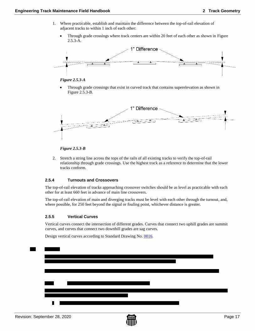
1. Where practicable, establish and maintain the difference between the top-of-rail elevation of
adjacent tracks to within 1 inch of each other:
Through grade crossings where track centers are within 20 feet of each other as shown in Figure
2.5.3-A.
Figure 2.5.3-A
Through grade crossings that exist in curved track that contains superelevation as shown in
Figure 2.5.3-B.
Figure 2.5.3-B
2. Stretch a string line across the tops of the rails of all existing tracks to verify the top-of-rail
relationship through grade crossings. Use the highest track as a reference to determine that the lower
tracks conform.
2.5.4 Turnouts and Crossovers
The top-of-rail elevation of tracks approaching crossover switches should be as level as practicable with each
other for at least 660 feet in advance of main line crossovers.
The top-of-rail elevation of main and diverging tracks must be level with each other through the turnout, and,
where possible, for 250 feet beyond the signal or fouling point, whichever distance is greater.
2.5.5 Vertical Curves
Vertical curves connect the intersection of different grades. Curves that connect two uphill grades are summit
curves, and curves that connect two downhill grades are sag curves.
Design vertical curves according to Standard Drawing No. 0016.

2 Track Geometry Engineering Track Maintenance Field Handbook
Page 18 Revision: September 28, 2020
Engineering Track Maintenance Field Handbook 2 Track Geometry
Revision: September 28, 2020 Page 19
2 Track Geometry Engineering Track Maintenance Field Handbook
Page 20 Revision: September 28, 2020
Engineering Track Maintenance Field Handbook 2 Track Geometry
Revision: September 28, 2020 Page 21

2 Track Geometry Engineering Track Maintenance Field Handbook
Page 22 Revision: September 28, 2020
2.6.5 Track Surface Limits
1. Track Surface Limits - Do not allow track surface to deviate from uniform profile and crosslevel
more than the following thresholds for the applicable class of track. Measure deviations as
prescribed by each category.
If maximum crosslevel in a curve is 6” or more and there is a difference in crosslevel between
any 2 points less than 62 feet apart of more than 1-1/2” the track is not good for any class of
track.
To control harmonics on Class 2 through 5 in jointed track with staggered joints, the cross-level
difference shall not exceed 1-1/4” in all of six consecutive pairs of joints, as created by 7 low
joints. Track with joints staggered less than 10 feet shall not be considered as having staggered
joints. Joints within the 7 low joints outside of the regular joint spacing shall not be considered
as joints for measurement.
Table 2.6.5-A shows Critical Limits
Track Surface Class
1
Class
2
Class
3
Class
4
Class
5
Class
6
The maximum crosslevel on the outside rail of a
curve may not be more than… 6" 6" 6" 6" 6" 6"
The runoff in any 31 feet of rail at the end of a raise
may not be more than… 3-1/2" 3" 2" 1-1/2" 1" N/A
The deviation from uniform profile on either rail at
the mid-ordinate of a 31-foot cord may not be
more than...
N/A N/A N/A N/A N/A 1"
The deviation from uniform profile on either rail at
the mid-ordinate of a 62-foot cord may not be
more than...
3" 2-3/4" 2-1/4" 2" 1-1/4" 1"
The deviation from uniform profile on either rail at
the mid-ordinate of a 124-foot cord may not be
more than...
N/A N/A N/A N/A N/A 1-3/4"
The deviation from zero crosslevel at any point on
tangent may not be more than… 3" 2" 1-3/4" 1-1/4" 1" 15/16"
The difference in crosslevel between any 2 points
less than 62 feet apart may not be more than… 3" 2-1/4" 2" 1-3/4" 1-1/2" 1-1/2"
The variation of crosslevel on the spiral per 31 feet
may not be more than: 2" 1 3/4" 1 1/4" 1" 3/4" 5/8"
The difference in crosslevel between any 2 points in
a curve less than 10 feet apart (Short Warp) may not
be more than…
N/A N/A N/A N/A N/A 1-1/4"
Table 2.6.5-A
2. Multiple Track Surface Deviation – Class 6 track only.
Do not allow track surface to deviate from uniformity more than the threshold for three or
more non-overlapping deviations occurring within a distance equal to five times the specified
cord length.
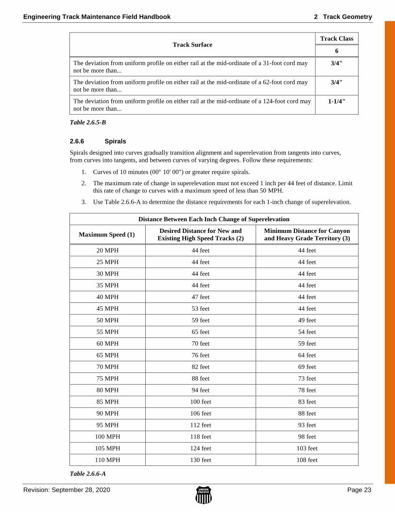
Table 2.6.5-B shows Critical Limits for Class 6.
Engineering Track Maintenance Field Handbook 2 Track Geometry
Revision: September 28, 2020 Page 23
Track Surface Track Class
6
The deviation from uniform profile on either rail at the mid-ordinate of a 31-foot cord may
not be more than... 3/4"
The deviation from uniform profile on either rail at the mid-ordinate of a 62-foot cord may
not be more than... 3/4"
The deviation from uniform profile on either rail at the mid-ordinate of a 124-foot cord may
not be more than... 1-1/4"
Table 2.6.5-B
2.6.6 Spirals
Spirals designed into curves gradually transition alignment and superelevation from tangents into curves,
from curves into tangents, and between curves of varying degrees. Follow these requirements:
1. Curves of 10 minutes (00 10' 00") or greater require spirals.
2. The maximum rate of change in superelevation must not exceed 1 inch per 44 feet of distance. Limit
this rate of change to curves with a maximum speed of less than 50 MPH.
3. Use Table 2.6.6-A to determine the distance requirements for each 1-inch change of superelevation.
Distance Between Each Inch Change of Superelevation
Maximum Speed (1) Desired Distance for New and
Existing High Speed Tracks (2)
Minimum Distance for Canyon
and Heavy Grade Territory (3)
20 MPH 44 feet 44 feet
25 MPH 44 feet 44 feet
30 MPH 44 feet 44 feet
35 MPH 44 feet 44 feet
40 MPH 47 feet 44 feet
45 MPH 53 feet 44 feet
50 MPH 59 feet 49 feet
55 MPH 65 feet 54 feet
60 MPH 70 feet 59 feet
65 MPH 76 feet 64 feet
70 MPH 82 feet 69 feet
75 MPH 88 feet 73 feet
80 MPH 94 feet 78 feet
85 MPH 100 feet 83 feet
90 MPH 106 feet 88 feet
95 MPH 112 feet 93 feet
100 MPH 118 feet 98 feet
105 MPH 124 feet 103 feet
110 MPH 130 feet 108 feet
Table 2.6.6-A

2 Track Geometry Engineering Track Maintenance Field Handbook
Page 24 Revision: September 28, 2020
4. If the length of the spiral permits, run superelevation off at a uniform rate over the entire length of
the spiral, with full superelevation through the body of the curve and no superelevation on tangent
track.
5. If no spirals exist, or spirals are too short to meet the required rate of runoff, a maximum of 1 inch of
superelevation may be run onto tangent track.
6. When the tangent between two curves is too short to provide the minimum length of runoff for the
authorized superelevation:
Divide the tangent into two parts in proportion to the degree of curvature of the adjoining
curves.
If possible, place the longer segment adjacent to the curve of greater degree.
7. Maintain at least 100 feet of level track between reverse curves, regardless of whether tangent track
exists or not, to ensure that cars can right themselves between curves.
8. Ensure that compound curves have full superelevation for the higher-degree curve carried through
the entire higher-degree portion of the curve and reduced superelevation on the lower-degree portion
of the curve within the prescribed runoff rates.
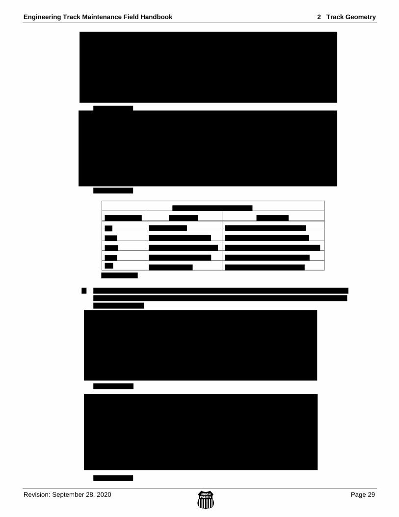
2.6.7 Superelevation
The outer or high rail of curves is the designated reference rail for installing and maintaining superelevation.
Maintain superelevation as provided on curve markers and/or designated on the high rail of curves.
The EFMS curve database that can be accessed through the Engineering Website may be used to
determine approved elevations and degree of curvature when there are no field markings on the
rail. If the accuracy of the EFMS curve database is in doubt, the Manager of Track Maintenance
should contact a Manager Geometry at 402-544-1037. Changes to the database cannot be made
without AVP Maintenance Approval.
NOTE: Designated superelevation may not be less than 3/4 inch or greater than 5 inches in any curve.
Install approved superelevation in main tracks when track renewals involve surfacing and lining.
Unless approved by the AVP Maintenance the designated superelevation is 1 inch unbalanced.
The AVP Maintenance must approve all changes to designated superelevation.
All speeds are rounded up to the nearest 1/4 inch.
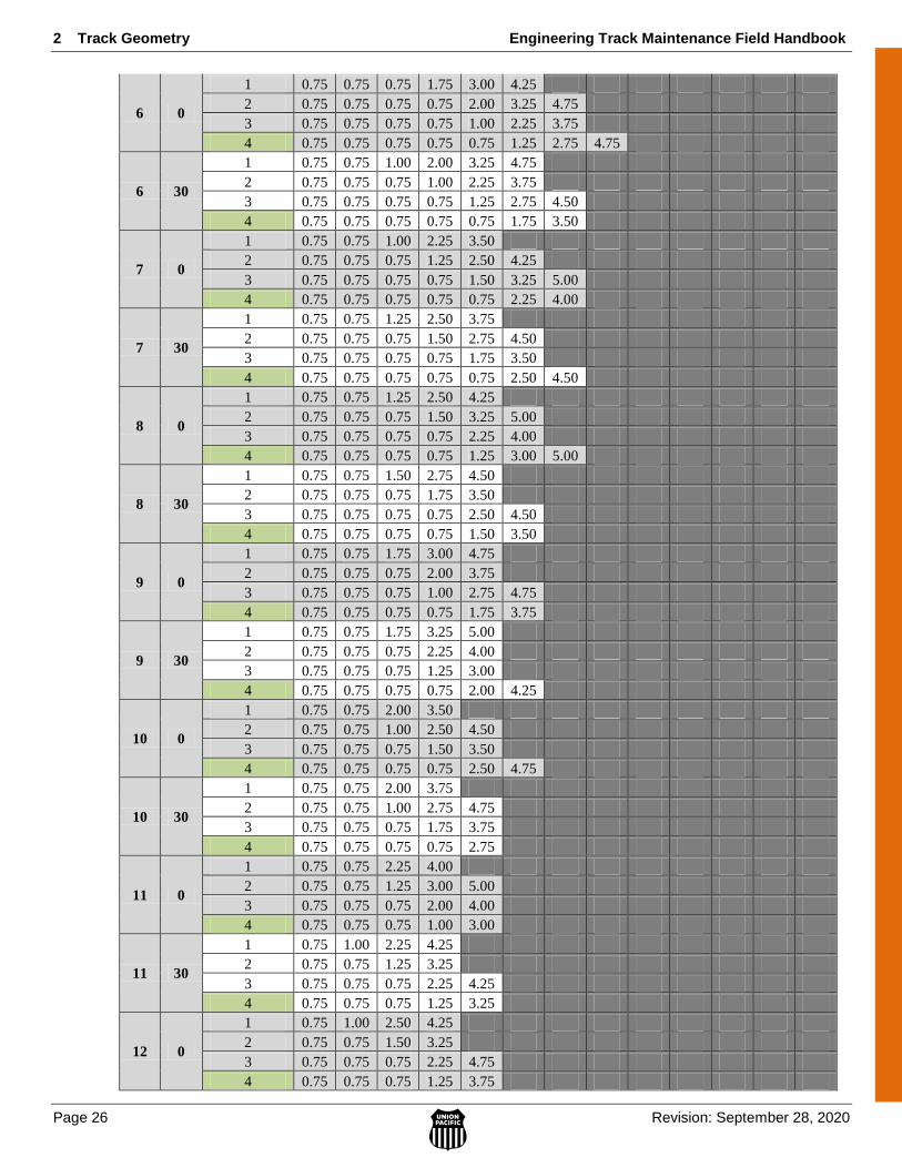
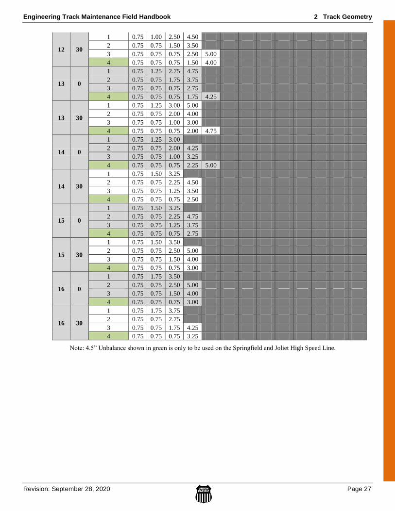
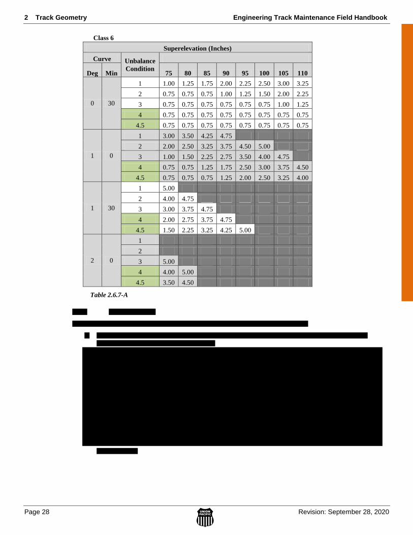
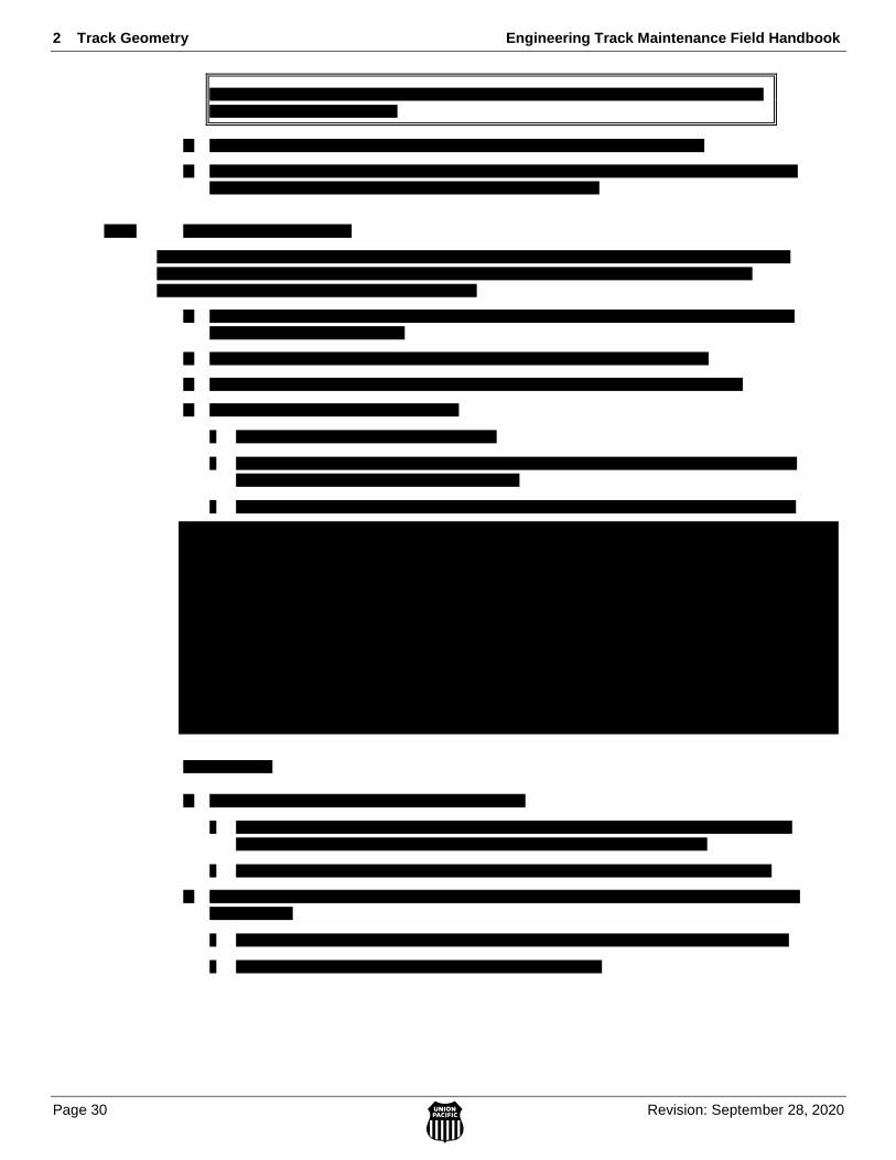
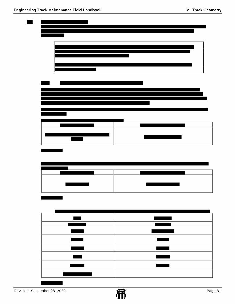
Use Table 2.6.7-A to design new superelevation.

Engineering Track Maintenance Field Handbook 2 Track Geometry
Revision: September 28, 2020 Page 25
Note: 4” Unbalance shown in green is for passenger operations only.
Class 1-5
Superelevation (Inches)
Curve Unbalanced
Condition
Curve Speeds (Miles Per Hour)
Deg Min 10 15 20 25 30 35 40 45 50 55 60 65 70
0 30
1 0.75 0.75 0.75 0.75 0.75 0.75 0.75 0.75 0.75 0.75 0.75 0.75 0.75
2 0.75 0.75 0.75 0.75 0.75 0.75 0.75 0.75 0.75 0.75 0.75 0.75 0.75
3 0.75 0.75 0.75 0.75 0.75 0.75 0.75 0.75 0.75 0.75 0.75 0.75 0.75
4 0.75 0.75 0.75 0.75 0.75 0.75 0.75 0.75 0.75 0.75 0.75 0.75 0.75
1 0
1 0.75 0.75 0.75 0.75 0.75 0.75 0.75 0.75 0.75 1.25 1.75 2.00 2.50
2 0.75 0.75 0.75 0.75 0.75 0.75 0.75 0.75 0.75 0.75 0.75 1.00 1.50
3 0.75 0.75 0.75 0.75 0.75 0.75 0.75 0.75 0.75 0.75 0.75 0.75 0.75
4 0.75 0.75 0.75 0.75 0.75 0.75 0.75 0.75 0.75 0.75 0.75 0.75 0.75
1 30
1 0.75 0.75 0.75 0.75 0.75 0.75 0.75 1.25 1.75 2.25 3.00 3.50 4.25
2 0.75 0.75 0.75 0.75 0.75 0.75 0.75 0.75 0.75 1.25 2.00 2.50 3.25
3 0.75 0.75 0.75 0.75 0.75 0.75 0.75 0.75 0.75 0.75 1.00 1.50 2.25
4 0.75 0.75 0.75 0.75 0.75 0.75 0.75 0.75 0.75 0.75 0.75 0.75 1.25
2 0
1 0.75 0.75 0.75 0.75 0.75 0.75 1.25 2.00 2.50 3.25 4.25 5.00
2 0.75 0.75 0.75 0.75 0.75 0.75 0.75 1.00 1.50 2.25 3.25 4.00 5.00
3 0.75 0.75 0.75 0.75 0.75 0.75 0.75 0.75 0.75 1.25 2.25 3.00 4.00
4 0.75 0.75 0.75 0.75 0.75 0.75 0.75 0.75 0.75 0.75 1.25 2.00 3.00
2 30
1 0.75 0.75 0.75 0.75 0.75 1.25 2.00 2.75 3.50 4.50
2 0.75 0.75 0.75 0.75 0.75 0.75 1.00 1.75 2.50 3.50 4.50
3 0.75 0.75 0.75 0.75 0.75 0.75 0.75 0.75 1.50 2.50 3.50 4.50
4 0.75 0.75 0.75 0.75 0.75 0.75 0.75 0.75 0.75 1.50 2.50 3.50 4.75
3 0
1 0.75 0.75 0.75 0.75 1.00 1.75 2.50 3.50 4.25
2 0.75 0.75 0.75 0.75 0.75 0.75 1.50 2.50 3.25 4.50
3 0.75 0.75 0.75 0.75 0.75 0.75 0.75 1.50 2.25 3.50 4.75
4 0.75 0.75 0.75 0.75 0.75 0.75 0.75 0.75 1.25 2.50 3.75 5.00
3 30
1 0.75 0.75 0.75 0.75 1.25 2.25 3.00 4.00
2 0.75 0.75 0.75 0.75 0.75 1.25 2.00 3.00 4.25
3 0.75 0.75 0.75 0.75 0.75 0.75 1.00 2.00 3.25 4.50
4 0.75 0.75 0.75 0.75 0.75 0.75 0.75 1.00 2.25 3.50 5.00
4 0
1 0.75 0.75 0.75 0.75 1.75 2.50 3.50 4.75
2 0.75 0.75 0.75 0.75 0.75 1.50 2.50 3.75 5.00
3 0.75 0.75 0.75 0.75 0.75 0.75 1.50 2.75 4.00
4 0.75 0.75 0.75 0.75 0.75 0.75 0.75 1.75 3.00 4.50
4 30
1 0.75 0.75 0.75 1.00 2.00 3.00 4.25
2 0.75 0.75 0.75 0.75 1.00 2.00 3.25 4.50
3 0.75 0.75 0.75 0.75 0.75 1.00 2.25 3.50 5.00
4 0.75 0.75 0.75 0.75 0.75 0.75 1.25 2.50 4.00
5 0
1 0.75 0.75 0.75 1.25 2.25 3.50 4.75
2 0.75 0.75 0.75 0.75 1.25 2.50 3.75
3 0.75 0.75 0.75 0.75 0.75 1.50 2.75 4.25
4 0.75 0.75 0.75 0.75 0.75 0.75 1.75 3.25 4.75
5 30
1 0.75 0.75 0.75 1.50 2.50 3.75
2 0.75 0.75 0.75 0.75 1.50 2.75 4.25
3 0.75 0.75 0.75 0.75 0.75 1.75 3.25 5.00
4 0.75 0.75 0.75 0.75 0.75 0.75 2.25 4.00
2 Track Geometry Engineering Track Maintenance Field Handbook
Page 26 Revision: September 28, 2020
6 0
1 0.75 0.75 0.75 1.75 3.00 4.25
2 0.75 0.75 0.75 0.75 2.00 3.25 4.75
3 0.75 0.75 0.75 0.75 1.00 2.25 3.75
4 0.75 0.75 0.75 0.75 0.75 1.25 2.75 4.75
6 30
1 0.75 0.75 1.00 2.00 3.25 4.75
2 0.75 0.75 0.75 1.00 2.25 3.75
3 0.75 0.75 0.75 0.75 1.25 2.75 4.50
4 0.75 0.75 0.75 0.75 0.75 1.75 3.50
7 0
1 0.75 0.75 1.00 2.25 3.50
2 0.75 0.75 0.75 1.25 2.50 4.25
3 0.75 0.75 0.75 0.75 1.50 3.25 5.00
4 0.75 0.75 0.75 0.75 0.75 2.25 4.00
7 30
1 0.75 0.75 1.25 2.50 3.75
2 0.75 0.75 0.75 1.50 2.75 4.50
3 0.75 0.75 0.75 0.75 1.75 3.50
4 0.75 0.75 0.75 0.75 0.75 2.50 4.50
8 0
1 0.75 0.75 1.25 2.50 4.25
2 0.75 0.75 0.75 1.50 3.25 5.00
3 0.75 0.75 0.75 0.75 2.25 4.00
4 0.75 0.75 0.75 0.75 1.25 3.00 5.00
8 30
1 0.75 0.75 1.50 2.75 4.50
2 0.75 0.75 0.75 1.75 3.50
3 0.75 0.75 0.75 0.75 2.50 4.50
4 0.75 0.75 0.75 0.75 1.50 3.50
9 0
1 0.75 0.75 1.75 3.00 4.75
2 0.75 0.75 0.75 2.00 3.75
3 0.75 0.75 0.75 1.00 2.75 4.75
4 0.75 0.75 0.75 0.75 1.75 3.75
9 30
1 0.75 0.75 1.75 3.25 5.00
2 0.75 0.75 0.75 2.25 4.00
3 0.75 0.75 0.75 1.25 3.00
4 0.75 0.75 0.75 0.75 2.00 4.25
10 0
1 0.75 0.75 2.00 3.50
2 0.75 0.75 1.00 2.50 4.50
3 0.75 0.75 0.75 1.50 3.50
4 0.75 0.75 0.75 0.75 2.50 4.75
10 30
1 0.75 0.75 2.00 3.75
2 0.75 0.75 1.00 2.75 4.75
3 0.75 0.75 0.75 1.75 3.75
4 0.75 0.75 0.75 0.75 2.75
11 0
1 0.75 0.75 2.25 4.00
2 0.75 0.75 1.25 3.00 5.00
3 0.75 0.75 0.75 2.00 4.00
4 0.75 0.75 0.75 1.00 3.00
11 30
1 0.75 1.00 2.25 4.25
2 0.75 0.75 1.25 3.25
3 0.75 0.75 0.75 2.25 4.25
4 0.75 0.75 0.75 1.25 3.25
12 0
1 0.75 1.00 2.50 4.25
2 0.75 0.75 1.50 3.25
3 0.75 0.75 0.75 2.25 4.75
4 0.75 0.75 0.75 1.25 3.75
Engineering Track Maintenance Field Handbook 2 Track Geometry
Revision: September 28, 2020 Page 27
12 30
1 0.75 1.00 2.50 4.50
2 0.75 0.75 1.50 3.50
3 0.75 0.75 0.75 2.50 5.00
4 0.75 0.75 0.75 1.50 4.00
13 0
1 0.75 1.25 2.75 4.75
2 0.75 0.75 1.75 3.75
3 0.75 0.75 0.75 2.75
4 0.75 0.75 0.75 1.75 4.25
13 30
1 0.75 1.25 3.00 5.00
2 0.75 0.75 2.00 4.00
3 0.75 0.75 1.00 3.00
4 0.75 0.75 0.75 2.00 4.75
14 0
1 0.75 1.25 3.00
2 0.75 0.75 2.00 4.25
3 0.75 0.75 1.00 3.25
4 0.75 0.75 0.75 2.25 5.00
14 30
1 0.75 1.50 3.25
2 0.75 0.75 2.25 4.50
3 0.75 0.75 1.25 3.50
4 0.75 0.75 0.75 2.50
15 0
1 0.75 1.50 3.25
2 0.75 0.75 2.25 4.75
3 0.75 0.75 1.25 3.75
4 0.75 0.75 0.75 2.75
15 30
1 0.75 1.50 3.50
2 0.75 0.75 2.50 5.00
3 0.75 0.75 1.50 4.00
4 0.75 0.75 0.75 3.00
16 0
1 0.75 1.75 3.50
2 0.75 0.75 2.50 5.00
3 0.75 0.75 1.50 4.00
4 0.75 0.75 0.75 3.00
16 30
1 0.75 1.75 3.75
2 0.75 0.75 2.75
3 0.75 0.75 1.75 4.25
4 0.75 0.75 0.75 3.25
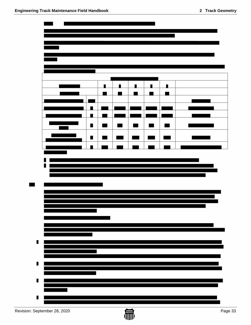
Note: 4.5” Unbalance shown in green is only to be used on the Springfield and Joliet High Speed Line.
2 Track Geometry Engineering Track Maintenance Field Handbook
Page 28 Revision: September 28, 2020
Class 6
Superelevation (Inches)
Curve Unbalance
Condition
Deg Min 75 80 85 90 95 100 105 110
0 30
1 1.00 1.25 1.75 2.00 2.25 2.50 3.00 3.25
2 0.75 0.75 0.75 1.00 1.25 1.50 2.00 2.25
3 0.75 0.75 0.75 0.75 0.75 0.75 1.00 1.25
4 0.75 0.75 0.75 0.75 0.75 0.75 0.75 0.75
4.5 0.75 0.75 0.75 0.75 0.75 0.75 0.75 0.75
1 0
1 3.00 3.50 4.25 4.75
2 2.00 2.50 3.25 3.75 4.50 5.00
3 1.00 1.50 2.25 2.75 3.50 4.00 4.75
4 0.75 0.75 1.25 1.75 2.50 3.00 3.75 4.50
4.5 0.75 0.75 0.75 1.25 2.00 2.50 3.25 4.00
1 30
1 5.00
2 4.00 4.75
3 3.00 3.75 4.75
4 2.00 2.75 3.75 4.75
4.5 1.50 2.25 3.25 4.25 5.00
2 0
1
2
3 5.00
4 4.00 5.00
4.5 3.50 4.50
Table 2.6.7-A
Engineering Track Maintenance Field Handbook 2 Track Geometry
Revision: September 28, 2020 Page 29
2 Track Geometry Engineering Track Maintenance Field Handbook
Page 30 Revision: September 28, 2020
Engineering Track Maintenance Field Handbook 2 Track Geometry
Revision: September 28, 2020 Page 31

2 Track Geometry Engineering Track Maintenance Field Handbook
Page 32 Revision: September 28, 2020
Engineering Track Maintenance Field Handbook 2 Track Geometry
Revision: September 28, 2020 Page 33
2 Track Geometry Engineering Track Maintenance Field Handbook
Page 34 Revision: September 28, 2020
2.9 Surveying and Marking Curves
Curve surveying is utilized to ensure curves are properly lined and surfaced. Surveying and marking of
curves is a method in which the curve is surveyed, calculated, and marked to guide maintenance or
construction gangs to either set the curve back to its original design or if due to current conditions that cannot
be achieved, a new design. During surfacing operations, when curve tamping solutions vary by the following
thresholds from the curve database or survey marks, then notify supervisor immediately for further
instructions unless otherwise notified that changes are correct.
1. Spiral Length change of 50% or more
2. Curve Length change of 500 feet or more
3. Curve degree change of 0.5° or more
4. Change in curve geometry from simple to compound or reduction in compounds
Curve Surveys are recommended to be prioritized by the following:
1. Ahead of Capital Program Undercutter projects.
2. Ahead of Capital Program Track, Surface, and Line projects
3. Ahead of Capital Program Tie Replacement projects.

Engineering Track Maintenance Field Handbook 3 Ties and Fastenings
Revision: November 19, 2020 Page 1
3.0 TIE
S &
FA
ST
EN
ING
S
3 TIES AND FASTENINGS
3.1 Ties ............................................................................................................................................................. 4
3.1.1 Types and Applications ............................................................................................................... 4 A. Wood Ties ............................................................................................................................ 4 B. Concrete Ties ........................................................................................................................ 5 C. Steel Ties .............................................................................................................................. 5 D. Composite Ties ..................................................................................................................... 5 E. Borate Treated Wood Ties .................................................................................................... 6
3.1.2 Installation and Spacing ............................................................................................................... 6
3.1.3 Switch Ties .................................................................................................................................. 8 A. Installing Switch Ties at Turnouts ........................................................................................ 8
B. Installing Switch Ties in Crossover Switches ....................................................................... 10
3.1.4 Head Block and Switch Machine Ties ......................................................................................... 11
3.1.5 Transition Zones .......................................................................................................................... 12
3.1.6 Tie Drilling – Wood and Composite Ties .................................................................................... 13
3.1.15 Concrete Tie Rating ..................................................................................................................... 19
3.3 Elastic Fasteners ......................................................................................................................................... 23
3.3.6 Insulated Joint Fastenings ............................................................................................................ 28
3.3.7 Weld-On Shoulders ..................................................................................................................... 28 A. Installing Non-Insulated Weld-on Shoulders........................................................................ 28
3 Ties and Fastenings Engineering Track Maintenance Field Handbook
Page 2 Revision: November 19, 2020
B. Installing Insulated Weld-on Shoulders ................................................................................ 28
C. Replacing Weld-on Shoulders .............................................................................................. 28
D. Welding Weld-on Shoulders ................................................................................................. 28
E. Installing Weld-on Shoulders in Various Applications ........................................................ 29
3.3.8 Hook-In Shoulders ....................................................................................................................... 30
3.4 Tie Plates .................................................................................................................................................... 30
3.4.2 Tie Plate Requirements ................................................................................................................ 30
3.4.3 Curve Blocks................................................................................................................................ 31
3.4.4 Elastic Fastener Plates.................................................................................................................. 32
3.5 Spikes and Screws ...................................................................................................................................... 33
3.5.1 Spikes (Cut Spikes) ...................................................................................................................... 33
3.5.2 Joint Spikes .................................................................................................................................. 33
3.5.3 Spike Pattern ................................................................................................................................ 34 A. Spiking Turnouts .................................................................................................................. 35 B. Spiking Road Crossings ........................................................................................................ 36
3.5.4 Lag Screw Application ................................................................................................................ 36
3.5.5 Evergrip Lag Screw ..................................................................................................................... 37
Engineering Track Maintenance Field Handbook 3 Ties and Fastenings
Revision: November 19, 2020 Page 3
3.0 TIE
S &
FA
ST
EN
ING
S
3 Ties and Fastenings Engineering Track Maintenance Field Handbook
Page 4 Revision: November 19, 2020
3.1 Ties
A tie is a support to which rails are fastened and held to gauge. Ties are designed to distribute wheel loads to the
roadbed and to interlock with ballast to prevent lateral, longitudinal and vertical movement of the track
structure.
3.1.1 Types and Applications
Determine the tie requirements for various track applications according to subsections A. Wood Ties, B.
Concrete Ties, C. Steel Ties, D. Composite ties and E. Borate Treated Wood Ties.
Tie Tier Map
A. Wood Ties
Follow these requirements when using wood ties:
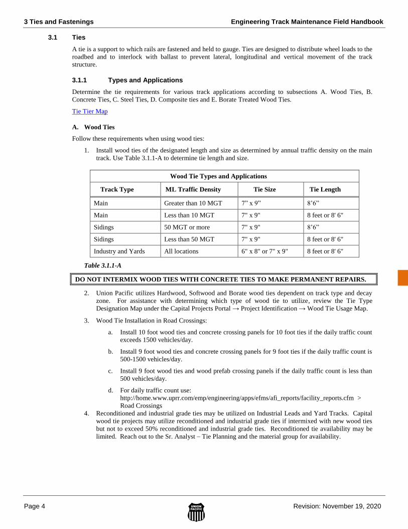
1. Install wood ties of the designated length and size as determined by annual traffic density on the main
track. Use Table 3.1.1-A to determine tie length and size.
Wood Tie Types and Applications
Track Type ML Traffic Density Tie Size Tie Length
Main Greater than 10 MGT 7” x 9” 8’6”
Main Less than 10 MGT 7" x 9" 8 feet or 8' 6"
Sidings 50 MGT or more 7" x 9" 8’6”
Sidings Less than 50 MGT 7" x 9" 8 feet or 8' 6"
Industry and Yards All locations 6" x 8" or 7" x 9" 8 feet or 8' 6"
Table 3.1.1-A
DO NOT INTERMIX WOOD TIES WITH CONCRETE TIES TO MAKE PERMANENT REPAIRS.
2. Union Pacific utilizes Hardwood, Softwood and Borate wood ties dependent on track type and decay
zone. For assistance with determining which type of wood tie to utilize, review the Tie Type
Designation Map under the Capital Projects Portal → Project Identification → Wood Tie Usage Map.
3. Wood Tie Installation in Road Crossings:
a. Install 10 foot wood ties and concrete crossing panels for 10 foot ties if the daily traffic count
exceeds 1500 vehicles/day.
b. Install 9 foot wood ties and concrete crossing panels for 9 foot ties if the daily traffic count is
500-1500 vehicles/day.
c. Install 9 foot wood ties and wood prefab crossing panels if the daily traffic count is less than
500 vehicles/day.
d. For daily traffic count use:
http://home.www.uprr.com/emp/engineering/apps/efms/afi_reports/facility_reports.cfm >
Road Crossings
4. Reconditioned and industrial grade ties may be utilized on Industrial Leads and Yard Tracks. Capital
wood tie projects may utilize reconditioned and industrial grade ties if intermixed with new wood ties
but not to exceed 50% reconditioned and industrial grade ties. Reconditioned tie availability may be
limited. Reach out to the Sr. Analyst – Tie Planning and the material group for availability.
Engineering Track Maintenance Field Handbook 3 Ties and Fastenings
Revision: November 19, 2020 Page 5
3.0 TIE
S &
FA
ST
EN
ING
S
B. Concrete Ties
Concrete Ties should only be utilized in concrete tie locations approved by the VP of Engineering. Refer to the
tie applications map. The fastening system is integrated into the concrete tie, see the Work Procedure
Document on fastening systems (WPD 3.01) for additional details.
Follow these requirements when installing ties in concrete tie track:
1. Clean and drain the ballast section. Proper track drainage is critical to concrete tie performance.
2. Concrete ties can be installed out of face in curves with high gauge restraint requirements located in
wood tie territory.
3. Ensure that the ballast section has a minimum depth of 12 inches below the bottom of the tie and a
minimum shoulder width of 12 inches.
4. Where guard rails are required on concrete ties, utilize the ties shown in Standard Drawing Nos. 0202
and 0206 with the platework shown in Standard Drawing No. 4004. Use only coach screws and
washers shown in Standard Drawing No. 0409. For Vossloh installations, utilize item numbers 503-
1956 on the ends and 503-1955, Vossloh applications do not require platework.
5. Concrete Tie Installation in Road Crossings:
a. Install 10 foot concrete ties and concrete crossing panels for 10 foot ties if the daily
traffic count exceeds 200 vehicles/day.
b. Install 8-6 foot concrete ties and concrete crossing panels for 8-6 foot ties if the daily
traffic count is less than 200 vehicles/day.
c. Use Item Number 540-1930 for crossing pads that will be installed on the UP11 and
UP15 (Rail.One) tie. Refer to Standard Drawing No. 0209 for tie details.
6. When handling concrete ties, ensure ties are carefully handled by mechanized equipment to avoid
chipping and breaking of concrete. Do not allow ties to drop more than 2 feet when unloading to the
ground; do not allow ties to drop on other ties.
C. Steel Ties
Steel Ties are recommended for specialty applications only, such as areas with specialized clearance
requirements. Examples of these locations are mechanical facilities, platform locations or areas where corrosive
materials may be present (i.e. locomotive facilities). Steel Tie Turnouts can be utilized in wood applications.
Follow the requirements in WPD on Steel Tie Installation and Maintenance when using steel ties.
D. Composite Ties
Composite Ties are ties manufactured out of materials other than concrete or wood. Polymer fiber reinforced is
the most common type utilized. They have specialized installation and maintenance requirements versus a
wood tie. Refer to WPD on Composite Tie Installation and Maintenance.
Composite ties have different spiking requirements than standard wood ties. In addition, they generally require
a pre-drill for lag screw and cut spike applications. On tangent track and curves up to 1 degree, use 1 gauge
spikes and 2 field spikes. The goal is to keep spikes from being side by side.
On all curves of 1 degree or greater, use 2 gauge and 2 field spikes.
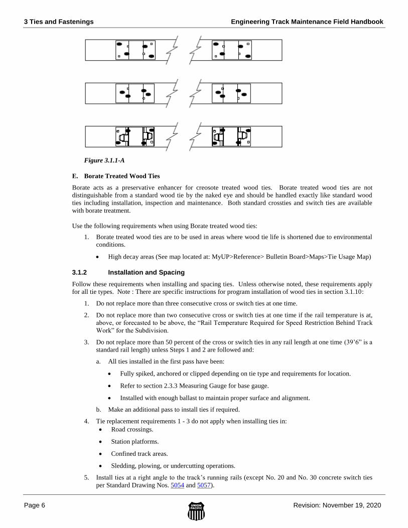
3 Ties and Fastenings Engineering Track Maintenance Field Handbook
Page 6 Revision: November 19, 2020
Figure 3.1.1-A
E. Borate Treated Wood Ties
Borate acts as a preservative enhancer for creosote treated wood ties. Borate treated wood ties are not
distinguishable from a standard wood tie by the naked eye and should be handled exactly like standard wood
ties including installation, inspection and maintenance. Both standard crossties and switch ties are available
with borate treatment.
Use the following requirements when using Borate treated wood ties:
1. Borate treated wood ties are to be used in areas where wood tie life is shortened due to environmental
conditions.
High decay areas (See map located at: MyUP>Reference> Bulletin Board>Maps>Tie Usage Map)
3.1.2 Installation and Spacing
Follow these requirements when installing and spacing ties. Unless otherwise noted, these requirements apply
for all tie types. Note : There are specific instructions for program installation of wood ties in section 3.1.10:
1. Do not replace more than three consecutive cross or switch ties at one time.
2. Do not replace more than two consecutive cross or switch ties at one time if the rail temperature is at,
above, or forecasted to be above, the “Rail Temperature Required for Speed Restriction Behind Track
Work” for the Subdivision.
3. Do not replace more than 50 percent of the cross or switch ties in any rail length at one time (39’6” is a
standard rail length) unless Steps 1 and 2 are followed and:
a. All ties installed in the first pass have been:
Fully spiked, anchored or clipped depending on tie type and requirements for location.
Refer to section 2.3.3 Measuring Gauge for base gauge.
Installed with enough ballast to maintain proper surface and alignment.
b. Make an additional pass to install ties if required.
4. Tie replacement requirements 1 - 3 do not apply when installing ties in:
Road crossings.
Station platforms.
Confined track areas.
Sledding, plowing, or undercutting operations.
5. Install ties at a right angle to the track’s running rails (except No. 20 and No. 30 concrete switch ties
per Standard Drawing Nos. 5054 and 5057).

Engineering Track Maintenance Field Handbook 3 Ties and Fastenings
Revision: November 19, 2020 Page 7
3.0 TIE
S &
FA
ST
EN
ING
S
6. Mark the inner rail of curves with appropriate tie spacing prior to removal. Maintaining proper tie
spacing in curves can be difficult without markings present.
7. Where tracks come together behind turnouts:
Do not interlace ties.
Maintain at least 3 inches between the ends of ties.
8. On wood tie applications install ties with “sap side” kerf marks (1/8” grooves cut into the top of the
tie) facing UP. This places the tie’s hardest surface down on the ballast as shown in Figure 3.1.2-A.
Different composite ties may have a designated “top” surface, consult the WPD on Composite Tie
installation for more information.
Figure 3.1.2-A
9. On wood and composite applications, it is important that the same distance of the tie extend away from
the rail seat on each side of the track. Failure to do so can result in tie length staggering which may
result in surface issues. Align the kerf mark in ties with the rail base of the designated line rail. Install
non-marked wood ties with the tie ends extending from the outside rail base of the line rail as shown in
Table 3.1.2-A.
Distance from Outside Rail Base to End of Wood Tie on Line Rail
Tie Application
Tie Length Outside Line Rail Base to End of Tie
Distance
Cross Tie 8 feet 15 inches
Cross Tie 8 feet 6 inches 18 inches
Cross Tie 9 feet 21 inches
Cross Tie 10 feet 27 inches
Switch Tie 10 to 17 feet *27 inches
Switch Tie 18 feet *21 to 27 inches
Switch Tie in Crossover
23 to 27 feet *21 to 27 inches with ties centered under the 2 tracks
Table 3.1.2-A
*NOTE: See Section 3.1.3 Switch Ties for additional information.
10. Prior to wood ties being re-spiked, plug the spike holes utilizing plugging compound or wooden
plugs.
11. When composite ties are re-spiked, re-spike into existing hole without plugging compound or plugs.
If changing the spiking pattern, re-drill pilot holes for new spike pattern.

3 Ties and Fastenings Engineering Track Maintenance Field Handbook
Page 8 Revision: November 19, 2020
12. When trains must operate through tie renewal areas during continued installation, adhere to the
minimum required number of ties left unspiked or unfastened outlined in Table 3.1.2-B.
Track Type Maximum Number of Consecutive Ties Left Unspiked
or Unfastened
Maximum Allowable Train Speed
(MPH)
Tangent 3 25
Curve 2 25
Table 3.1.2-B
13. Maintain a minimum number of ties at the designated spacing in each 39 feet of track as determined by
the tie and track type. Use Table 3.1.2-C to determine the quantities.
Tie Quantities Per 39 Feet of Track and Required Spacing
Tie Type Main Track Sidings and Yards
7" x 8’6" Wood/ Composite
24 ties @ 19-1/2 inches 20 ties @ 24 inches
6" x 8" Wood Do not use 22 ties @ 21-1/4 inches
Concrete 20 ties @ 24 inches 20 ties @ 24 inches
7 1/2” x 8’6” Steel Do not use 20 ties @ 24 inches
Table 3.1.2-C
NOTE: When converting an existing wood tie curve to concrete ties, the tie spacing may be
reduced to 19-1/2 inches to allow for easier installation and increased gauge restraint.
14. Install and space ties under rail joints with the centerline of the tie measuring between 9 and 18 inches
from the rail end. Ensure that tie spacing will allow for field welding of joints to avoid re-spacing ties.
3.1.3 Switch Ties
The standards that apply to cross ties also apply to switch ties. Follow these general switch tie requirements:
1. Maintain a standard set of switch ties in every turnout according to the applicable Standard Drawing.
Do not install cross ties in turnouts in place of switch ties to make a permanent repair.
Do not cut switch ties to make shorter lengths. Exception – If switch is being straight railed.
2. When ordering replacement concrete or steel ties, specify the turnout size, hand, individual tie number,
tie generation, HST present, tie spacing and frog type.
NOTE: Unlike wood ties in wood tie turnouts, each concrete or steel switch tie in a turnout is
unique. The ties are individually numbered for identification. Concrete turnout ties span
multiple generations and tie spacings. To avoid errors in ordering and for assistance with
ordering contact Sr. Manager Tie Assessment.
A. Installing Switch Ties at Turnouts
Follow these requirements when installing switch ties:
1. Install 10-foot switch ties ahead of the switch points in main track and siding switches according to
Standard Drawing No. 0270.
2. Install 10-foot switch ties under the full length of the switch points. You may use 9-foot ties in yard
track switches where the track configuration does not give enough clearance between tie ends of
adjacent track.
3. Ensure that wood switch ties extend 27 inches from the outside base of the designated line rail on the
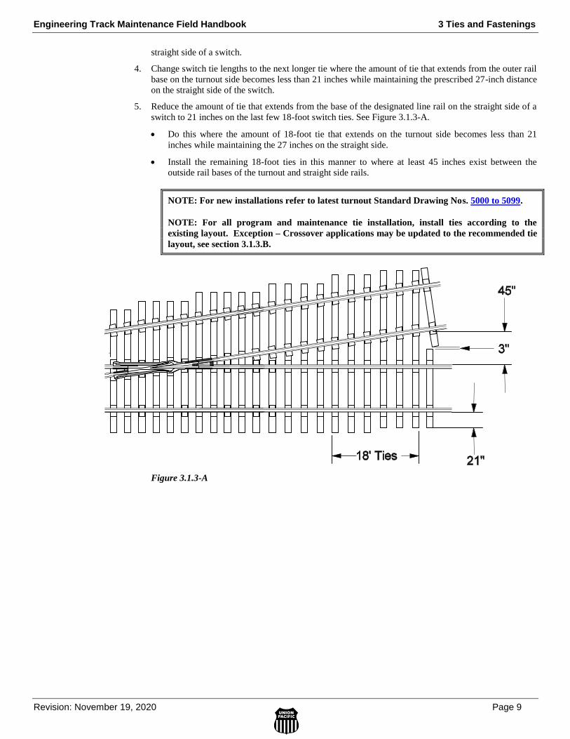
Engineering Track Maintenance Field Handbook 3 Ties and Fastenings
Revision: November 19, 2020 Page 9
3.0 TIE
S &
FA
ST
EN
ING
S
straight side of a switch.
4. Change switch tie lengths to the next longer tie where the amount of tie that extends from the outer rail
base on the turnout side becomes less than 21 inches while maintaining the prescribed 27-inch distance
on the straight side of the switch.
5. Reduce the amount of tie that extends from the base of the designated line rail on the straight side of a
switch to 21 inches on the last few 18-foot switch ties. See Figure 3.1.3-A.
Do this where the amount of 18-foot tie that extends on the turnout side becomes less than 21
inches while maintaining the 27 inches on the straight side.
Install the remaining 18-foot ties in this manner to where at least 45 inches exist between the
outside rail bases of the turnout and straight side rails.
NOTE: For new installations refer to latest turnout Standard Drawing Nos. 5000 to 5099.
NOTE: For all program and maintenance tie installation, install ties according to the
existing layout. Exception – Crossover applications may be updated to the recommended tie
layout, see section 3.1.3.B.
Figure 3.1.3-A

3 Ties and Fastenings Engineering Track Maintenance Field Handbook
Page 10 Revision: November 19, 2020
B. Installing Switch Ties in Crossover Switches
Follow these requirements when installing switch ties in crossover switches:
1. In 2004 UP modified its crossover switch tie layout. The previous layouts had all long ties 23’ and
larger under the entire crossover. The revised layout shown in Figure 3.1.3-B utilizes staggered long
and short ties where every third tie is a long tie (23’ to 27’).
2. During program switch tie replacement, upgrading to the new staggered layout is advised. This may
require that tie lengths be changed over several replacement cycles in order to fully upgrade to the new
standard layout.
3. Measure track centers in wood tie track to determine the length of staggered long switch ties required
in crossover switches where ties extend under both tracks. See Table 3.1.3-A.
Long Switch Tie Lengths for Crossover Switches
Existing Track Center Long Switch Tie Length
13 feet to 13 feet 11 inches 23 feet
14 feet to 14 feet 11 inches 24 feet
15 feet to 15 feet 11 inches 25 feet
16 feet to 16 feet 11 inches 26 feet
17 feet to 17 feet 11 inches 27 feet
18 feet or greater Not required
Table 3.1.3-A
NOTE: In crossover switches, staggered long switch ties extending under both tracks replace
shorter length switch ties used in standard turnouts where track centers are less than 18 feet.
Old switch tie pattern consisted of all long ties - when replacing ties, update to current design.
4. At crossover switches where the track centers do not measure in even feet, center the long switch ties
under both tracks, with 21 to 27 inches extending from the outer rail base of the designated line rails.
5. The ideal pattern is to have two short ties to one long tie, as shown in Figure 3.1.3-B. Previous
crossover switches had all longer ties (23’ to 27’) under the switch. There are certain track centers that
will require a change in the pattern in the center of the crossover (where the two turnouts meet). One
rule to remember here is that at no time shall two long ties be placed next to each other.
Figure 3.1.3-B
6. On original standard crossovers, i.e. crossovers that utilize all long ties, use Table 3.1.3-B below to
determine the shorter length switch ties replaced by long switch ties in crossover switches. This does
not apply to the new staggered standard.
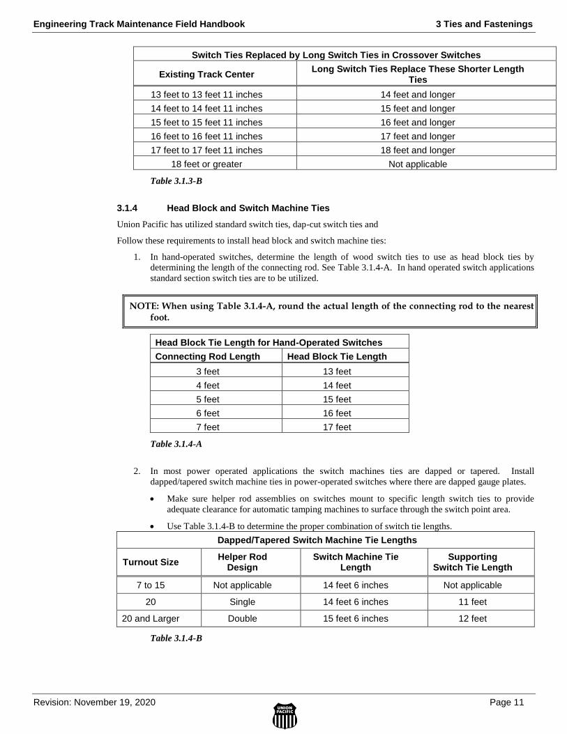
Engineering Track Maintenance Field Handbook 3 Ties and Fastenings
Revision: November 19, 2020 Page 11
3.0 TIE
S &
FA
ST
EN
ING
S
Switch Ties Replaced by Long Switch Ties in Crossover Switches
Existing Track Center Long Switch Ties Replace These Shorter Length
Ties
13 feet to 13 feet 11 inches 14 feet and longer
14 feet to 14 feet 11 inches 15 feet and longer
15 feet to 15 feet 11 inches 16 feet and longer
16 feet to 16 feet 11 inches 17 feet and longer
17 feet to 17 feet 11 inches 18 feet and longer
18 feet or greater Not applicable
Table 3.1.3-B
3.1.4 Head Block and Switch Machine Ties
Union Pacific has utilized standard switch ties, dap-cut switch ties and
Follow these requirements to install head block and switch machine ties:
1. In hand-operated switches, determine the length of wood switch ties to use as head block ties by
determining the length of the connecting rod. See Table 3.1.4-A. In hand operated switch applications
standard section switch ties are to be utilized.
NOTE: When using Table 3.1.4-A, round the actual length of the connecting rod to the nearest foot.
Head Block Tie Length for Hand-Operated Switches
Connecting Rod Length Head Block Tie Length
3 feet 13 feet
4 feet 14 feet
5 feet 15 feet
6 feet 16 feet
7 feet 17 feet
Table 3.1.4-A
2. In most power operated applications the switch machines ties are dapped or tapered. Install
dapped/tapered switch machine ties in power-operated switches where there are dapped gauge plates.
Make sure helper rod assemblies on switches mount to specific length switch ties to provide
adequate clearance for automatic tamping machines to surface through the switch point area.
Use Table 3.1.4-B to determine the proper combination of switch tie lengths.
Dapped/Tapered Switch Machine Tie Lengths
Turnout Size Helper Rod
Design Switch Machine Tie
Length Supporting
Switch Tie Length
7 to 15 Not applicable 14 feet 6 inches Not applicable
20 Single 14 feet 6 inches 11 feet
20 and Larger Double 15 feet 6 inches 12 feet
Table 3.1.4-B

3 Ties and Fastenings Engineering Track Maintenance Field Handbook
Page 12 Revision: November 19, 2020
3. Switches size 20 and greater often utilize helper rods to assist with throwing the switch as shown in
Figure 3.1.4-A. Use the standard drawing for the turnout and consult with the signal group to assist
with the installation location for helper rod supporting switch ties.
Figure 3.1.4-A
3.1.5 Transition Zones
Follow the requirements in Standard Drawing 0270 for transition zones:
1. Install wood ties of specific lengths with elastic fasteners to transition to wood turnouts and standard
concrete ties to transition from wood ties to concrete turnouts as shown in Table 3.1.5-A.
Elastically Fastened Wood Tie and Standard Concrete Tie Requirements for Turnout Transitions
When transitioning from...
And maximum train speed is...
Then install...
Wood Ties to Wood
Tie Turnouts
More than 40 MPH on
Mainline Side
Forty 10-foot ties ahead of the
switch points and Twenty-four 8’-
6”-foot ties behind the last long
switch tie on the mainline side
Wood Ties to Wood
Tie Turnouts
More than 40 MPH on
Mainline Side and More
than 35 MPH on Turnout
Side Track
Forty 10-foot ties ahead of the
switch points and Twenty-four 8’-6”
ties behind the last long switch tie
on both mainline and turnout sides
Wood Ties to
Concrete Tie Turnouts
More than 40 MPH on
Mainline Side and More
than 35 MPH on Turnout
Side Track
Forty standard concrete ties ahead
of the switch points and Twenty
standard concrete ties behind the
last long switch tie on both mainline
and turnout sides
Table 3.1.5-A
2. Install transition zone ties on the approaches of open deck bridges as show in Table 3.1.5-B.
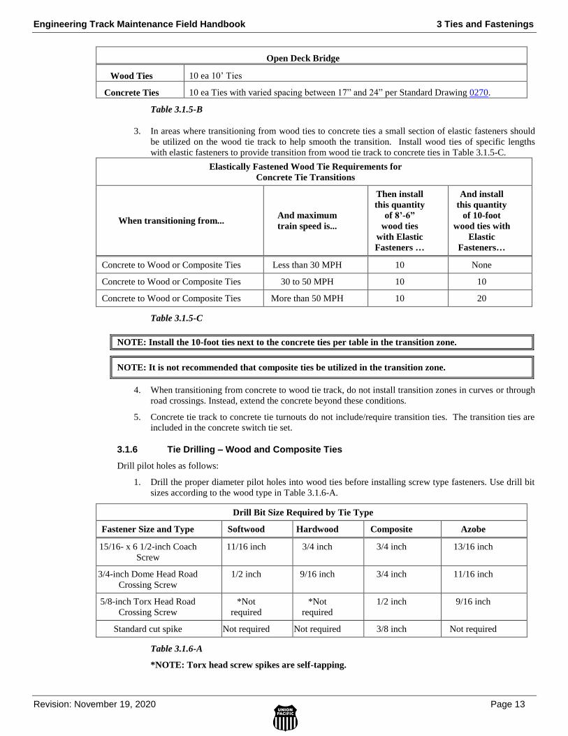
Engineering Track Maintenance Field Handbook 3 Ties and Fastenings
Revision: November 19, 2020 Page 13
3.0 TIE
S &
FA
ST
EN
ING
S
Open Deck Bridge
Wood Ties 10 ea 10’ Ties
Concrete Ties 10 ea Ties with varied spacing between 17” and 24” per Standard Drawing 0270.
Table 3.1.5-B
3. In areas where transitioning from wood ties to concrete ties a small section of elastic fasteners should
be utilized on the wood tie track to help smooth the transition. Install wood ties of specific lengths
with elastic fasteners to provide transition from wood tie track to concrete ties in Table 3.1.5-C.
Elastically Fastened Wood Tie Requirements for
Concrete Tie Transitions
When transitioning from... And maximum
train speed is...
Then install
this quantity
of 8’-6”
wood ties
with Elastic
Fasteners …
And install
this quantity
of 10-foot
wood ties with
Elastic
Fasteners…
Concrete to Wood or Composite Ties Less than 30 MPH 10 None
Concrete to Wood or Composite Ties 30 to 50 MPH 10 10
Concrete to Wood or Composite Ties More than 50 MPH 10 20
Table 3.1.5-C
NOTE: Install the 10-foot ties next to the concrete ties per table in the transition zone.
NOTE: It is not recommended that composite ties be utilized in the transition zone.
4. When transitioning from concrete to wood tie track, do not install transition zones in curves or through
road crossings. Instead, extend the concrete beyond these conditions.
5. Concrete tie track to concrete tie turnouts do not include/require transition ties. The transition ties are
included in the concrete switch tie set.
3.1.6 Tie Drilling – Wood and Composite Ties
Drill pilot holes as follows:
1. Drill the proper diameter pilot holes into wood ties before installing screw type fasteners. Use drill bit
sizes according to the wood type in Table 3.1.6-A.
Drill Bit Size Required by Tie Type
Fastener Size and Type Softwood Hardwood Composite Azobe
15/16- x 6 1/2-inch Coach
Screw
11/16 inch 3/4 inch 3/4 inch 13/16 inch
3/4-inch Dome Head Road
Crossing Screw
1/2 inch 9/16 inch 3/4 inch 11/16 inch
5/8-inch Torx Head Road
Crossing Screw
*Not
required
*Not
required
1/2 inch 9/16 inch
Standard cut spike Not required Not required 3/8 inch Not required
Table 3.1.6-A
*NOTE: Torx head screw spikes are self-tapping.
3 Ties and Fastenings Engineering Track Maintenance Field Handbook
Page 14 Revision: November 19, 2020
2. Drill ties 1/4 inch below the lowest point where the screw fastener will penetrate the tie. Ensure that
pilot holes do not extend through the bottom of the ties.

Engineering Track Maintenance Field Handbook 3 Ties and Fastenings
Revision: November 19, 2020 Page 15
3.0 TIE
S &
FA
ST
EN
ING
S

3 Ties and Fastenings Engineering Track Maintenance Field Handbook
Page 16 Revision: November 19, 2020
Engineering Track Maintenance Field Handbook 3 Ties and Fastenings
Revision: November 19, 2020 Page 17
3.0 TIE
S &
FA
ST
EN
ING
S
3 Ties and Fastenings Engineering Track Maintenance Field Handbook
Page 18 Revision: November 19, 2020

Engineering Track Maintenance Field Handbook 3 Ties and Fastenings
Revision: November 19, 2020 Page 19
3.0 TIE
S &
FA
ST
EN
ING
S
3.1.15 Concrete Tie Rating
Concrete tie rating is very different from rating wood ties. Refer to the WPD on Tie Rating for guidelines.

3 Ties and Fastenings Engineering Track Maintenance Field Handbook
Page 20 Revision: November 19, 2020
Engineering Track Maintenance Field Handbook 3 Ties and Fastenings
Revision: November 19, 2020 Page 21
3.0 TIE
S &
FA
ST
EN
ING
S

3 Ties and Fastenings Engineering Track Maintenance Field Handbook
Page 22 Revision: November 19, 2020
Engineering Track Maintenance Field Handbook 3 Ties and Fastenings
Revision: November 19, 2020 Page 23
3.0 TIE
S &
FA
ST
EN
ING
S
3.3 Elastic Fasteners Elastic Fasteners are any fastener that acts as a “spring” to hold the base of the rail down with much higher
force than standard cut spikes. They are often referred to as spring clips because of this. Due to higher loading
they often reduce the requirement for anchors over standard cut spikes. All concrete tie fastening systems are
elastic fasteners. Wood tie elastic fasteners include e-clips and Safelok I clips. Table 3.3.8-A shows the most
common spring clip types. Refer to the WPD on Fastening Systems for more information.
3 Ties and Fastenings Engineering Track Maintenance Field Handbook
Page 24 Revision: November 19, 2020
Engineering Track Maintenance Field Handbook 3 Ties and Fastenings
Revision: November 19, 2020 Page 25
3.0 TIE
S &
FA
ST
EN
ING
S

3 Ties and Fastenings Engineering Track Maintenance Field Handbook
Page 26 Revision: November 19, 2020
Engineering Track Maintenance Field Handbook 3 Ties and Fastenings
Revision: November 19, 2020 Page 27
3.0 TIE
S &
FA
ST
EN
ING
S

3 Ties and Fastenings Engineering Track Maintenance Field Handbook
Page 28 Revision: November 19, 2020
3.3.6 Insulated Joint Fastenings
Install insulated joint bar insulators between special spring insulated joint clips and the rail base of bonded
insulated joints on concrete, steel, or wood ties that use the Safelok system. See Standard Drawing No. 0410 or
0414 depending on clip type. For an insulated joint e-clip see Standard Drawing No. 0437.
NOTE: Joints in concrete tie track directly across from one another cannot be insulated.
3.3.7 Weld-On Shoulders
Safelok weld-on shoulders are insulated or non-insulated and differ by height. The insulated shoulder is
approximately 5/16 inch higher than the non-insulated as shown in Table 3.3.7-A.
Weld-On Shoulder Types and Dimensions
Shoulder Type Approximate Height
Non-Insulated 1-1/8 inch
Insulated 1-7/16 inch
Table 3.3.7-A
Safelok weld-on shoulder applications include:
Special plate work fastened to concrete, wood or steel ties in turnouts.
Plate work directly applied to steel turnout ties at the frog base.
A. Installing Non-Insulated Weld-on Shoulders
Install non-insulated weld-on shoulders:
To plate work where spring clips fasten the rail base.
Directly to steel turnout ties to fasten the rail base of other than self-guarded frogs.
B. Installing Insulated Weld-on Shoulders
Install insulated weld-on shoulders:
To plate work under insulated or standard joints.
To frog plates where spring clips fasten to the thicker base of self-guarded frogs in wood
turnouts.
Directly to steel turnout ties to fasten to the thicker rail base of self-guarded frogs.
C. Replacing Weld-on Shoulders
Replace weld-on shoulders damaged from derailments or other causes when they do not effectively hold the rail
clip in place.
Replace damaged weld-on shoulders with similar shoulders.
D. Welding Weld-on Shoulders
Weld weld-on shoulders to special plate work or steel turnout ties with a 3/8-inch fillet weld using an E7018
welding rod.
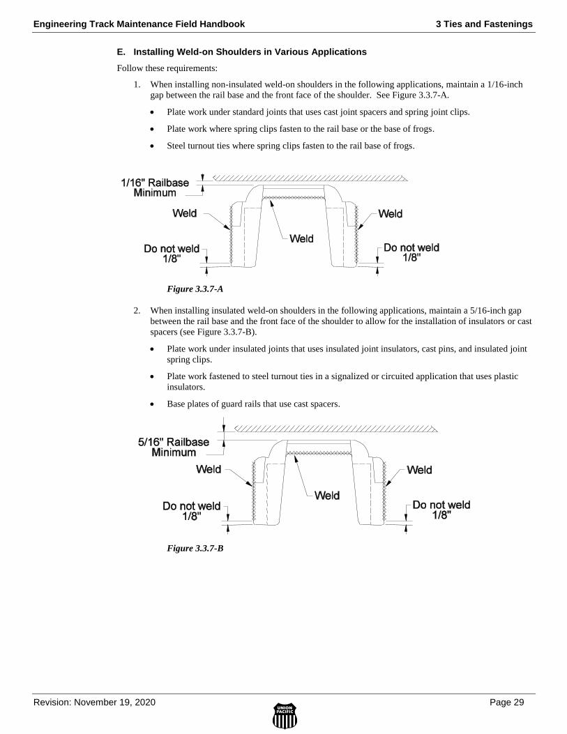
Engineering Track Maintenance Field Handbook 3 Ties and Fastenings
Revision: November 19, 2020 Page 29
3.0 TIE
S &
FA
ST
EN
ING
S
E. Installing Weld-on Shoulders in Various Applications
Follow these requirements:
1. When installing non-insulated weld-on shoulders in the following applications, maintain a 1/16-inch
gap between the rail base and the front face of the shoulder. See Figure 3.3.7-A.
Plate work under standard joints that uses cast joint spacers and spring joint clips.
Plate work where spring clips fasten to the rail base or the base of frogs.
Steel turnout ties where spring clips fasten to the rail base of frogs.
Figure 3.3.7-A
2. When installing insulated weld-on shoulders in the following applications, maintain a 5/16-inch gap
between the rail base and the front face of the shoulder to allow for the installation of insulators or cast
spacers (see Figure 3.3.7-B).
Plate work under insulated joints that uses insulated joint insulators, cast pins, and insulated joint
spring clips.
Plate work fastened to steel turnout ties in a signalized or circuited application that uses plastic
insulators.
Base plates of guard rails that use cast spacers.
Figure 3.3.7-B
3 Ties and Fastenings Engineering Track Maintenance Field Handbook
Page 30 Revision: November 19, 2020
3.3.8 Hook-In Shoulders
Steel cross and switch ties use hook-in shoulders to apply spring clips. The hook-in shoulder must match the
steel tie thickness.
1. Identify the proper hook-in shoulder from Table 3.3.8-A.
Table 3.3.8-A
2. Replace hook-in shoulders damaged from derailments or other causes when they do not effectively
hold the rail clip in place.
3.4 Tie Plates
3.4.2 Tie Plate Requirements
Follow these requirements when installing tie plates:
1. Apply tie plates to all wood and composite ties.
2. Do not intermix plates of different sizes and cant along the same rail.
NOTE: Cut spike plates and lag screw plates can be intermixed if they have the same rail seat cant.
This would be done for the purposes of replacing the lag screw fastening system with cut spikes for
maintenance or program work. When replacing lag screw plates with cut spike plates on consecutive
ties as a permanent repair, rail anchors must be used. Victor plates with spikes are elastic fasteners
and do not require anchors.
Hook-In Shoulder Types and Steel Tie Dimensions
Shoulder Type Steel Tie Type Tie Thickness
12 millimeter Existing Tunnel or Mainline Ties 12 millimeter
10 millimeter Yard Track Tie 10 millimeter
10 millimeter Turnout Tie 10 millimeter
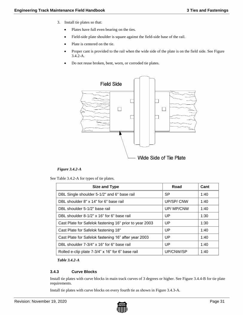
Engineering Track Maintenance Field Handbook 3 Ties and Fastenings
Revision: November 19, 2020 Page 31
3.0 TIE
S &
FA
ST
EN
ING
S
3. Install tie plates so that:
Plates have full even bearing on the ties.
Field-side plate shoulder is square against the field-side base of the rail.
Plate is centered on the tie.
Proper cant is provided to the rail when the wide side of the plate is on the field side. See Figure
3.4.2-A.
Do not reuse broken, bent, worn, or corroded tie plates.
Figure 3.4.2-A
See Table 3.4.2-A for types of tie plates.
Size and Type Road Cant
DBL Single shoulder 5-1/2" and 6" base rail SP 1:40
DBL shoulder 8" x 14" for 6" base rail UP/SP/ CNW 1:40
DBL shoulder 5-1/2" base rail UP/ MP/CNW 1:40
DBL shoulder 8-1/2" x 16" for 6" base rail UP 1:30
Cast Plate for Safelok fastening 16" prior to year 2003 UP 1:30
Cast Plate for Safelok fastening 18" UP 1:40
Cast Plate for Safelok fastening 16” after year 2003 UP 1:40
DBL shoulder 7-3/4" x 16" for 6" base rail UP 1:40
Rolled e-clip plate 7-3/4” x 16” for 6” base rail UP/CNW/SP 1:40
Table 3.4.2-A
3.4.3 Curve Blocks
Install tie plates with curve blocks in main track curves of 3 degrees or higher. See Figure 3.4.4-B for tie plate
requirements.
Install tie plates with curve blocks on every fourth tie as shown in Figure 3.4.3-A.

3 Ties and Fastenings Engineering Track Maintenance Field Handbook
Page 32 Revision: November 19, 2020
Figure 3.4.3-A
3.4.4 Elastic Fastener Plates
Elastic fastener plates are used in specific locations to assist in holding gauge, and areas of special track work.
Victor plates are the standard elastic fastener plates for high degree curves. (Figure 3.4.4-A) Note: For
compound curves, use greatest degree curvature to determine plate type.
Note: For compound curves, use the greatest degree of curvature to determine plate type.
1. Curves less than 3 degrees will use 16” double shoulder cut spike plates
2. Curves 3 degrees and greater will utilize curve block plates on both high and low sides on subdivisions
with less than 20 MGT.
3. Subdivisions with 20 MGT or more will utilize 16” Victor plates with cut spikes on curves 3 degrees and
greater.
4. Non-Mainline Tracks will default to < 20 MGT. Exceptions due to operating conditions should be
reviewed with Director Rail Management 402-544-5079.
Figure 3.4.4-A
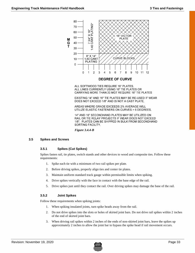
Engineering Track Maintenance Field Handbook 3 Ties and Fastenings
Revision: November 19, 2020 Page 33
3.0 TIE
S &
FA
ST
EN
ING
S
Figure 3.4.4-B
3.5 Spikes and Screws
3.5.1 Spikes (Cut Spikes)
Spikes fasten rail, tie plates, switch stands and other devices to wood and composite ties. Follow these
requirements:
1. Spike each tie with a minimum of two rail spikes per plate.
2. Before driving spikes, properly align ties and center tie plates.
3. Maintain uniform standard track gauge within permissible limits when spiking.
4. Drive spikes vertically with the face in contact with the base edge of the rail.
5. Drive spikes just until they contact the rail. Over driving spikes may damage the base of the rail.
3.5.2 Joint Spikes
Follow these requirements when spiking joints:
1. When spiking insulated joints, turn spike heads away from the rail.
2. Do not drive spikes into the slots or holes of skirted joint bars. Do not drive rail spikes within 2 inches
of the end of skirted joint bars.
3. When driving rail spikes within 2 inches of the ends of non-skirted joint bars, leave the spikes up
approximately 2 inches to allow the joint bar to bypass the spike head if rail movement occurs.
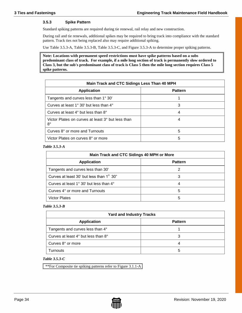
3 Ties and Fastenings Engineering Track Maintenance Field Handbook
Page 34 Revision: November 19, 2020
3.5.3 Spike Pattern
Standard spiking patterns are required during tie renewal, rail relay and new construction.
During rail and tie renewals, additional spikes may be required to bring track into compliance with the standard
pattern. Track ties not being replaced also may require additional spiking.
Use Table 3.5.3-A, Table 3.5.3-B, Table 3.5.3-C, and Figure 3.5.3-A to determine proper spiking patterns.
Note: Locations with permanent speed restrictions must have spike patterns based on a subs
predominant class of track. For example, if a mile long section of track is permanently slow ordered to
Class 3, but the sub's predominant class of track is Class 5 then the mile long section requires Class 5
spike patterns.
Main Track and CTC Sidings Less Than 40 MPH
Application Pattern
Tangents and curves less than 1° 30' 1
Curves at least 1° 30' but less than 4° 3
Curves at least 4° but less than 8° 4
Victor Plates on curves at least 3° but less than 8°
4
Curves 8° or more and Turnouts 5
Victor Plates on curves 8° or more 5
Table 3.5.3-A
Main Track and CTC Sidings 40 MPH or More
Application Pattern
Tangents and curves less than 30' 2
Curves at least 30’ but less than 1o 30” 3
Curves at least 1° 30' but less than 4° 4
Curves 4° or more and Turnouts 5
Victor Plates 5
Table 3.5.3-B
Yard and Industry Tracks
Application Pattern
Tangents and curves less than 4° 1
Curves at least 4° but less than 8° 3
Curves 8° or more 4
Turnouts 5
Table 3.5.3-C
**For Composite tie spiking patterns refer to Figure 3.1.1-A.
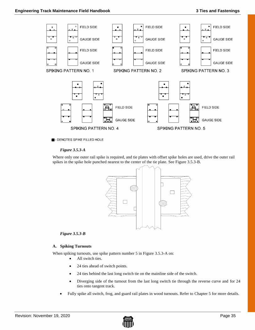
Engineering Track Maintenance Field Handbook 3 Ties and Fastenings
Revision: November 19, 2020 Page 35
3.0 TIE
S &
FA
ST
EN
ING
S
Figure 3.5.3-A
Where only one outer rail spike is required, and tie plates with offset spike holes are used, drive the outer rail
spikes in the spike hole punched nearest to the center of the tie plate. See Figure 3.5.3-B.
Figure 3.5.3-B
A. Spiking Turnouts
When spiking turnouts, use spike pattern number 5 in Figure 3.5.3-A on:
All switch ties.
24 ties ahead of switch points.
24 ties behind the last long switch tie on the mainline side of the switch.
Diverging side of the turnout from the last long switch tie through the reverse curve and for 24
ties onto tangent track.
Fully spike all switch, frog, and guard rail plates in wood turnouts. Refer to Chapter 5 for more details.
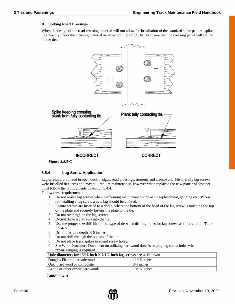
3 Ties and Fastenings Engineering Track Maintenance Field Handbook
Page 36 Revision: November 19, 2020
B. Spiking Road Crossings
When the design of the road crossing material will not allow for installation of the standard spike pattern, spike
ties directly under the crossing material as shown in Figure 3.5.3-C to ensure that the crossing panel will set flat
on the ties.
Figure 3.5.3-C
3.5.4 Lag Screw Application
Lag screws are utilized in open deck bridges, road crossings, turnouts and crossovers. Historically lag screws
were installed in curves and may still require maintenance, however when replaced the new plate and fastener
must follow the requirements in section 3.4.4.
Follow these requirements:
1. Do not re-use lag screws when performing maintenance such as tie replacement, gauging etc. When
re-installing a lag screw a new lag should be utilized.
2. Ensure screws are inserted to a depth, where the bottom of the head of the lag screw is touching the top
of the plate and securely fastens the plate to the tie.
3. Do not over tighten the lag screws.
4. Do not drive lag screws into the tie.
5. Use the proper size drill bit for the type of tie when drilling holes for lag screws as referred to in Table
3.5.4-A.
6. Drill holes to a depth of 6 inches.
7. Do not drill through the bottom of the tie.
8. Do not place track spikes in round screw holes.
9. See Work Procedure Document on utilizing hardwood dowels to plug lag screw holes when
repair/gauging is required.
Hole diameters for 15/16-inch X 6 1/2-inch lag screws are as follows:
Douglas Fir or other softwood 11/16 inches
Oak , hardwood or composite 3/4 inches
Azobe or other exotic hardwoods 13/16 inches
Table 3.5.4-A
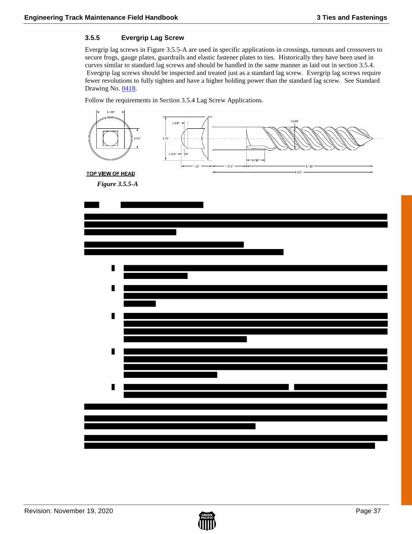
Engineering Track Maintenance Field Handbook 3 Ties and Fastenings
Revision: November 19, 2020 Page 37
3.0 TIE
S &
FA
ST
EN
ING
S
3.5.5 Evergrip Lag Screw
Evergrip lag screws in Figure 3.5.5-A are used in specific applications in crossings, turnouts and crossovers to
secure frogs, gauge plates, guardrails and elastic fastener plates to ties. Historically they have been used in
curves similar to standard lag screws and should be handled in the same manner as laid out in section 3.5.4.
Evergrip lag screws should be inspected and treated just as a standard lag screw. Evergrip lag screws require
fewer revolutions to fully tighten and have a higher holding power than the standard lag screw. See Standard
Drawing No. 0418.
Follow the requirements in Section 3.5.4 Lag Screw Applications.
Figure 3.5.5-A
Engineering Track Maintenance Field Handbook 4 Rail and Joints
Revision: February 4, 2022 Page 1
4 RAIL AND JOINTS
4.1 General ....................................................................................................................................................... 5
4.2 Rail Relays and Wear Limits ..................................................................................................................... 5
4.2.1 Classification and Use of Secondhand Rail .......................................................................... 5
A. Acceptable Lengths .............................................................................................................. 6
B. Wear Measurement References ............................................................................................ 6
C. Weld Plant Classification Parameters ................................................................................... 6
D. Internal Defects ..................................................................................................................... 6
E. Drilled Stick Rail .................................................................................................................. 6
F. Marking of Classified Rails .................................................................................................. 7
G. Shipment Requirements of Stick Rail ................................................................................... 7
H. Rail with Bolt Holes ............................................................................................................. 7
4.2.2 Out-of-Face Rail Relays ....................................................................................................... 7
A. Critical Curve Wear (CCW) ................................................................................................. 9
4.3 Inner Guard Rails ....................................................................................................................................... 10
4.6 Compromise Joint Bars .............................................................................................................................. 10
4.6.1 Step (“Non-Handed”) Joint Bars .......................................................................................... 10
4.6.2 Compromise/Transition Rails ............................................................................................... 11
4.7 Rail Joints ................................................................................................................................................... 12
4.7.1 Permanent Joints ................................................................................................................... 12
4.7.2 Joint Placement and Support ................................................................................................. 13
4.7.3 Rail Joint Stagger and Rail Joints Near Bridge Approaches ................................................. 13
4.8 Insulated Joints ........................................................................................................................................... 16
4.8.1 Types and Applications ........................................................................................................ 17
4.8.2 Poly-Coated and Fiberglass Insulated Joints ........................................................................ 17
A. Poly-Coated Insulated Joints ................................................................................................ 17
B. Fiberglass Insulated Joints .................................................................................................... 17
4 Rail and Joints Engineering Track Maintenance Field Handbook
Page 2 Revision: February 4, 2022
4.12 Weld Tolerance Specifications ................................................................................................................... 21
4.13 Vertical Rail Stiffness Equipment (VERSE) .............................................................................................. 21
4.14.3 Standard Box Pattern ............................................................................................................ 24
4.14.4 Solid Box Pattern .................................................................................................................. 24
4.14.5 Bridge Pattern ....................................................................................................................... 25
4.14.6 Turnout Pattern ..................................................................................................................... 25
4.14.7 Transition Pattern .................................................................................................................. 27
4.14.8 Crossing Frogs ...................................................................................................................... 27

Engineering Track Maintenance Field Handbook 4 Rail and Joints
Revision: February 4, 2022 Page 3
4.18 Rail Handling ............................................................................................................................................. 51
4 Rail and Joints Engineering Track Maintenance Field Handbook
Page 4 Revision: February 4, 2022
Engineering Track Maintenance Field Handbook 4 Rail and Joints
Revision: February 4, 2022 Page 5
4.1 General
CWR - Continuously Welded Rail is any section of rail that is joint free for 400' or greater. Once rail becomes
classified as CWR it remains CWR.
Jointed Rail - Rail that is broken into individual sticks of rail (generally 39'-6" segments) and bolted together.
Note - Installing joints in CWR sections does not constitute jointed rail.
4.2 Rail Relays and Wear Limits
Out-of-face rail and curve relay programs are based on accumulated gross tonnage, defect rates, and rail head
wear.
4.2.1 Classification and Use of Secondhand Rail
The specification and inspection parameters below detail the guidelines for the secondhand rail standards. These
standards will be used to grade secondhand rail for recovery for re-use, or purchase from outside sources. The
instructions outlined below are designed to provide consistent evaluation of secondhand rail throughout the
system so that each rail is properly marked for its identity and use. Refer to Figure 4.2.1-A and Table 4.2.1-A.
NOTE: DO NOT TRANSPOSE RAIL. TRANSPOSED RAIL IS SECONDHAND RAIL THAT HAS
HAD TRAFFIC RUN ON ONE SIDE INITIATING THE WEAR PROCESS AND THEN IS FLIPPED
SO THE OTHER SIDE IS RUN ON.
Class 1-Principal use is for main line replacement rails, rail relays on lines carrying between 5 and 20 MGT per
year and other areas requiring long term serviceable secondhand rail.
Class 2-Principal use is for secondary main line or siding replacement rails, rail relays of lines carrying less than
5 MGT per year, yard or industry tracks and other areas of low track speeds or demands on serviceable
secondhand rail.
Class 3-Principal use is for yard or industry tracks and other areas of temporary service or low demands on
quantity of secondhand rail.
4 Rail and Joints Engineering Track Maintenance Field Handbook
Page 6 Revision: February 4, 2022
A. Acceptable Lengths
The minimum acceptable length for secondhand rail classified at the weld plant is 25 feet. Minimum length for a
plug rail is 15 feet.
B. Wear Measurement References
Vertical head measurement will be taken from the center of the rail's head (+/- 3/8") to its base plane (excluding
base pitting). See Section 4.3.4 Curve Rail Wear Limits. Determine gauge face wear loss by measuring the
width of the railhead at a point 5/8" below the top surface of the railhead.
Engineering Track Maintenance Field Handbook 4 Rail and Joints
Revision: February 4, 2022 Page 7
4.2.2 Out-of-Face Rail Relays
For a list of guidelines of approved rail sections for out-of-face rail relay programs, refer to the Union Pacific
Standard Rail Sections map. See Maps in the Engineering Bulletin Board on the Engineering Website.
Follow these requirements:
1. When second-hand rail is unavailable, a different rail size or kind may be substituted.
2. Under no circumstances will rail, with a roll date older than 1975, be installed in any main line
application.
3. During concrete tie renewals (TRT), replace existing rail when:
The rail section is not 133 lb., 136 lb. or 141 lb. head hardened.
Vertical head loss is 3/8 inch or more.
Rail defect rate meets or exceeds replacement logic.
4 Rail and Joints Engineering Track Maintenance Field Handbook
Page 8 Revision: February 4, 2022
.

Engineering Track Maintenance Field Handbook 4 Rail and Joints
Revision: February 4, 2022 Page 9

4 Rail and Joints Engineering Track Maintenance Field Handbook
Page 10 Revision: February 4, 2022
4.3 Inner Guard Rails
Refer to Engineering Standard Drawing Nos. 4000 to 4004 to determine which structures require inner guard
rails. Refer to Engineering Standard Drawing Nos. 4005 to 4008 to determine turnout guard rail use. These
drawings also show construction details.
Follow these guidelines for keeping inner guard rails fully plated, bolted and spiked:
1. On tangent track, spike the inner guard rail with two spikes per plate on each rail on the tangent portion,
and four spikes per plate on each rail on the curved portion.
2. On curved track, spike the entire inner guard rail with four rail spikes per plate on each rail.
3. Do not install joints in the curved portion of the inner guard rail except where an insulated joint is
required in signalized territory.
4. The rules with regards to Torch Cut Rail and Torch Cut Bolt Holes do not apply to inner guard rails.
Inner guard rails may be torch cut to fit and can utilize torch cut bolt holes.
4.6 Compromise Joint Bars
Compromise joint bars align the tread and gauge lines of adjoining rails of different sizes.
NOTE: Compromise joint bars are marked with the weight of the rail on each side. Utilizing bars
that are not correct for the rail section can result in an increased chance of premature failure.
4.6.1 Step (“Non-Handed”) Joint Bars
Step or “non-handed” joint bars align the tread area of rails with the same rail base size. Apply step joint bars
when the difference in the width of rails does not exceed 1/8 inch at gauge lines.
1. Bars are identified as A and B. Together they make up a joint set that fit either side of the rail.
2. Depending on which rail the joint bars are to be applied, the individual bars will be placed on either the
gauge side or field side of the rail. See Figure 4.6.1-A.
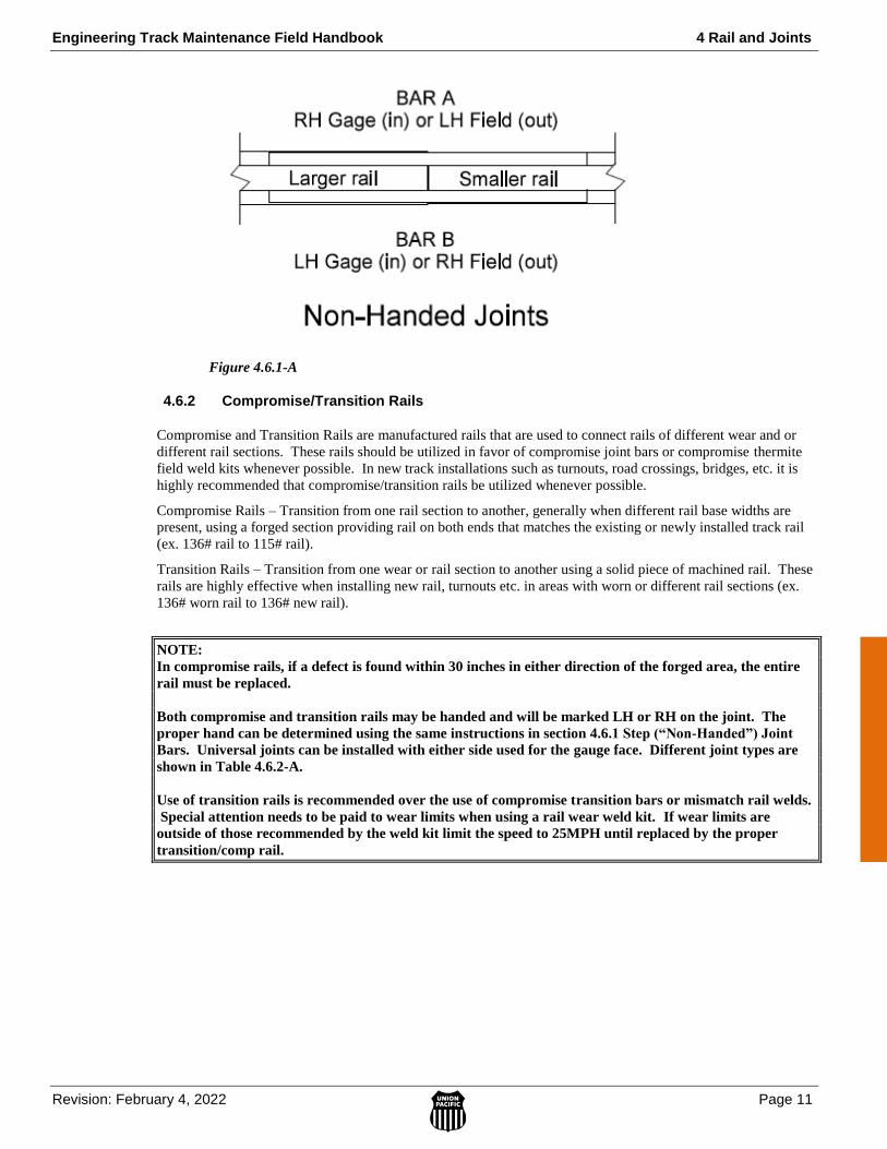
Engineering Track Maintenance Field Handbook 4 Rail and Joints
Revision: February 4, 2022 Page 11
Figure 4.6.1-A
4.6.2 Compromise/Transition Rails
Compromise and Transition Rails are manufactured rails that are used to connect rails of different wear and or
different rail sections. These rails should be utilized in favor of compromise joint bars or compromise thermite
field weld kits whenever possible. In new track installations such as turnouts, road crossings, bridges, etc. it is
highly recommended that compromise/transition rails be utilized whenever possible.
Compromise Rails – Transition from one rail section to another, generally when different rail base widths are
present, using a forged section providing rail on both ends that matches the existing or newly installed track rail
(ex. 136# rail to 115# rail).
Transition Rails – Transition from one wear or rail section to another using a solid piece of machined rail. These
rails are highly effective when installing new rail, turnouts etc. in areas with worn or different rail sections (ex.
136# worn rail to 136# new rail).
NOTE:
In compromise rails, if a defect is found within 30 inches in either direction of the forged area, the entire
rail must be replaced.
Both compromise and transition rails may be handed and will be marked LH or RH on the joint. The
proper hand can be determined using the same instructions in section 4.6.1 Step (“Non-Handed”) Joint
Bars. Universal joints can be installed with either side used for the gauge face. Different joint types are
shown in Table 4.6.2-A.
Use of transition rails is recommended over the use of compromise transition bars or mismatch rail welds.
Special attention needs to be paid to wear limits when using a rail wear weld kit. If wear limits are
outside of those recommended by the weld kit limit the speed to 25MPH until replaced by the proper
transition/comp rail.

4 Rail and Joints Engineering Track Maintenance Field Handbook
Page 12 Revision: February 4, 2022
Available Compromise/Transition Rails
Rail Section
Vertical Wear
Rail Section
Vertical Wear Hand
Total Length
Item Number
115 NEW 90 3/8" LH 25' 552-2219
115 NEW 90 3/8" RH 25' 552-2220
133 NEW 115 1/8" LH 20' 552-3820
133 NEW 115 1/8" RH 20' 552-3821
136 1/4" 115 NEW LH 24' 552-4385
136 1/4" 115 NEW RH 24' 552-4386
136 NEW 115 NEW LH 24' 552-4387
136 NEW 115 NEW RH 24' 552-4388
136 NEW 115 3/16" LH 24' 552-4389
136 NEW 115 3/16" RH 24' 552-4390
136 7/8" 115 3/8" UNIVERSAL 37' 6" 552-4407
136 NEW 133 7/8" UNIVERSAL 37' 6" 552-4393
136 NEW 136 7/8" UNIVERSAL 40' 552-4395
141 NEW 115 NEW LH 24' 552-4402
141 NEW 115 NEW RH 24' 552-4403
141 NEW 133 7/8" UNIVERSAL 37' 6" 552-4400
141 NEW 132 11/16” UNIVERSAL 40' 552-4405
Table 4.6.2-A
4.7 Rail Joints
The rail joint consists of the rail area and Other Track Material (OTM) within the entire length of the joint bars.
NOTE: If rail has been torch cut, remove with rail saw, 2 or more inches of rail before installing rail to
make a joint.
4.7.1 Permanent Joints
Permanent joints are joints that are not intended to have the rail ends welded together.
Permanent joints include:
Insulated joints.
Joints in bolted rail territory.
Joints in CWR that will remain in track
o Examples are: Joints in non-extended turnouts and crossing frogs

Engineering Track Maintenance Field Handbook 4 Rail and Joints
Revision: February 4, 2022 Page 13
Permanent joints must be:
Fully drilled.
Fully bolted.
Bolt holes and rail ends to be beveled and slotted per Standard Drawing No. 0721. To de-burr and bevel holes drilled in the field, use abrasive stone item number 411-3867.
Fully box anchored per Section 4.15 Rail Anchors in CWR territory.
4.7.2 Joint Placement and Support
Joints must be properly supported by the correct tie arrangement. Reference Section 3.1.9 Joint Tie Support for
minimum requirements.
To enable joint removal in CWR with thermite field welds, do the following:
1. Except in an emergency to pass trains over a broken rail, joints must not be located within:
30 inches from an existing plant or in-track weld or 15’ from an existing rail joint or field weld on subdivisions listed in table 4.10.1-1 or as specified by the AVP Maintenance.
NOTE: The only exception to this 15’ weld rule is in special track work around or near turnouts
and rail crossings (diamonds) where because of geometry layout or component spacing, the 15’ is
not obtainable.
30 inches from an existing rail joint or weld of any type on subdivisions not listed in table 4.10.1-1
NOTE: In order to prevent weld clusters or a multitude of field welds installed closely together,
no more than two field welds are allowed in the same length of rail (plant weld to plant weld), rule
doesn’t apply to long rail, 320’ and 480’ lengths.
NOTE: When installing replacement rail, effort must be made to eliminate thermite welds.
2. Center joints between ties to enable field welds to be made without moving or adzing tie. Field welds
must not be located directly over a tie. Refer to Section 4.11 Field Welding (Thermite).
4.7.3 Rail Joint Stagger and Rail Joints Near Bridge Approaches
Follow these requirements for staggering rail joints:
1. The standard stagger between consecutive rail joints on opposite rails is 12 feet, plus or minus 2 feet.
2. Staggered rail joints are preferred but not required on industry leads and yard tracks where the speed
does not exceed 25 MPH and the curvature is less than 4 degrees.
3. Bridge approach guidelines
Installation of new track panels through the bridge on the mainline must have rail joints and welds
no closer than 5’ from the abutment off the bridge, and thermite welds no closer than 25’ from the
abutment off the bridge. Reference Standard Drawing No. 6007.
If rail joints and/or welds are present within this area, a 25 MPH slow order will be applied.
4. When trying to figure the stagger of rail around a curve use this rule of thumb:
For every 80 feet of rail laid, the low rail will become 1 1/2 inches longer for every one degree of
curvature.

4 Rail and Joints Engineering Track Maintenance Field Handbook
Page 14 Revision: February 4, 2022
Engineering Track Maintenance Field Handbook 4 Rail and Joints
Revision: February 4, 2022 Page 15

4 Rail and Joints Engineering Track Maintenance Field Handbook
Page 16 Revision: February 4, 2022
4.8 Insulated Joints
Insulated joint bars perform the same function as standard joint bars. In addition, they isolate the rail ends from
each other to allow the signal track circuit to work properly. Figure 4.8-A shows a typical cut section.
Requirements for inspection and remedial actions for defective insulated joints are located in Section 7.11.6
Insulated Joint Bar Inspections.
Figure 4.8-A
1. Verify the proper placement of insulated joints with a signal representative before moving their location
or installing a new location.
2. The track and signal departments are jointly responsible for installing and maintaining insulated joints.
3. Remove from track as soon as practical. Maintain joint inspection frequency and IJ condition
assessment frequency until removed.
4. On wood ties do not place the middle of an insulated joint on top of a tie plate.
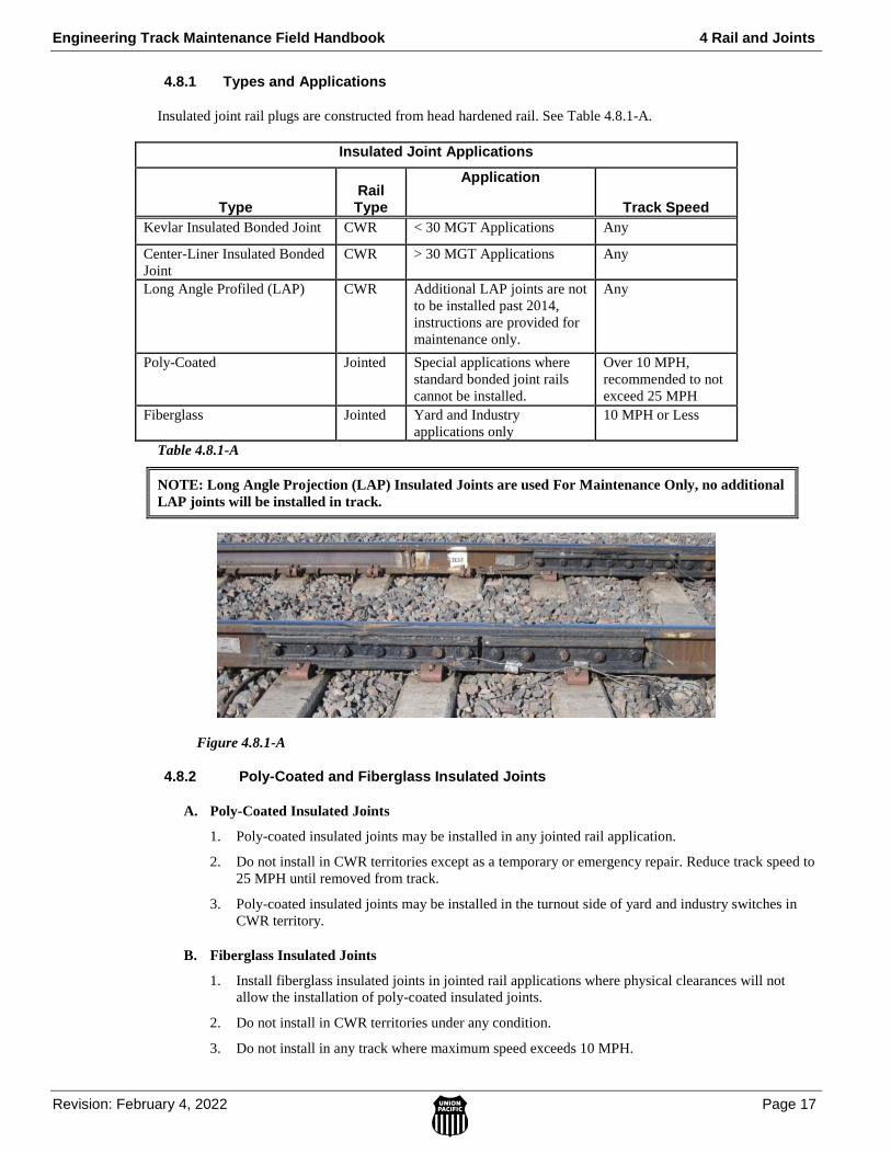
Engineering Track Maintenance Field Handbook 4 Rail and Joints
Revision: February 4, 2022 Page 17
4.8.1 Types and Applications
Insulated joint rail plugs are constructed from head hardened rail. See Table 4.8.1-A.
Insulated Joint Applications
Type Rail Type
Application
Track Speed
Kevlar Insulated Bonded Joint CWR < 30 MGT Applications Any
Center-Liner Insulated Bonded
Joint
CWR > 30 MGT Applications Any
Long Angle Profiled (LAP) CWR Additional LAP joints are not
to be installed past 2014,
instructions are provided for
maintenance only.
Any
Poly-Coated Jointed Special applications where
standard bonded joint rails
cannot be installed.
Over 10 MPH,
recommended to not
exceed 25 MPH
Fiberglass Jointed Yard and Industry
applications only
10 MPH or Less
Table 4.8.1-A
NOTE: Long Angle Projection (LAP) Insulated Joints are used For Maintenance Only, no additional
LAP joints will be installed in track.
Figure 4.8.1-A
4.8.2 Poly-Coated and Fiberglass Insulated Joints
A. Poly-Coated Insulated Joints
1. Poly-coated insulated joints may be installed in any jointed rail application.
2. Do not install in CWR territories except as a temporary or emergency repair. Reduce track speed to
25 MPH until removed from track.
3. Poly-coated insulated joints may be installed in the turnout side of yard and industry switches in
CWR territory.
B. Fiberglass Insulated Joints
1. Install fiberglass insulated joints in jointed rail applications where physical clearances will not
allow the installation of poly-coated insulated joints.
2. Do not install in CWR territories under any condition.
3. Do not install in any track where maximum speed exceeds 10 MPH.
4 Rail and Joints Engineering Track Maintenance Field Handbook
Page 18 Revision: February 4, 2022
Engineering Track Maintenance Field Handbook 4 Rail and Joints
Revision: February 4, 2022 Page 19
4 Rail and Joints Engineering Track Maintenance Field Handbook
Page 20 Revision: February 4, 2022

Engineering Track Maintenance Field Handbook 4 Rail and Joints
Revision: February 4, 2022 Page 21
4.12 Weld Tolerance Specifications
To improve overall track geometry and reduce Evaluation Car exceptions, Thermite, Mobile In-Track and Plant
weld maximum geometry tolerances below must be followed. Use the following table when auditing weld
geometry.
These are cold (ambient temperature), finish ground specifications.
Auditing welds instructions can be accessed using the WPD Auditing Welds.
Use Table 4.12-A to determine weld tolerance specifications for Class 1 through Class 6 Tracks.
Weld Type
Vertical
Offset (1)
Combined
Vertical
Offset and
Vertical
Crown (2)
Horizontal
Offset (3)
Combined
Horizontal
Offset and
Horizontal
Kink (4)
Base
Horizontal
Offset (5)
Base
Vertical
Offset (6)
Thermite 0.020” 0.040” 0.030” 0.040” 0.060” 0.250”
In-Track (Class 1-5) 0.025” 0.060” 0.030” 0.040” 0.060” New
0.100” SH
0.125”
In-Track (Class 6) 0.020” 0.030” 0.030” 0.040” 0.060” 0.125”
Plant - (New and Classified 1 Rail) 0.025” 0.060” 0.030” 0.040” 0.060” 0.060”
Plant – (Classified 2 & 3 Rail) 0.050” 0.080” 0.050” 0.065” 0.100” 0.125”
Table 4.12-A
1. Vertical Offset measured adjacent to weld and tapered.
2. Combined Vertical Offset and Vertical Crown not to exceed maximum stated limit as measured 18"
from center of weld.
3. Horizontal offset measured adjacent to weld on gauge side of rail head.
a. Plant weld measurement checked on either side of rail head. (Check both sides for uniformity).
4. Combined Horizontal Offset and Horizontal Kink not to exceed maximum stated limit as measured 18"
from center of weld.
5. Base Horizontal Offset measured adjacent to weld not to exceed maximum stated limit.
6. Base Vertical Offset measure adjacent to weld not to exceed maximum limit (any offset on top of rail
must be tapered to reduce impact forces).
a. Measurement not to exceed 0.250” on thermite welds of same base width.
b. Measurement not to exceed 0.125” on in-track welds and Plant welds Classified 2 and 3 SH
rail.
c. Measurement not to exceed 0.060” on new Plant welds and Classified 1 SH rail.
4.13 Vertical Rail Stiffness Equipment (VERSE)
Vertical Rail Stiffness Equipment (VERSE) is a system developed for measuring the RNT of continuous welded
rails (CWR). The system is based on the principle that the vertical force required to lift a rail varies with the axial
force contained within the rail due to stressing. VERSE fulfils the need for a simple non-destructive RNT
measurement technique.
4 Rail and Joints Engineering Track Maintenance Field Handbook
Page 22 Revision: February 4, 2022
VERSE measurements will be in accordance with the Work Procedure Document for VERSE Testing and
reporting the test results can be completed by accessing the VERSE web page in the TMP.
Engineering Track Maintenance Field Handbook 4 Rail and Joints
Revision: February 4, 2022 Page 23
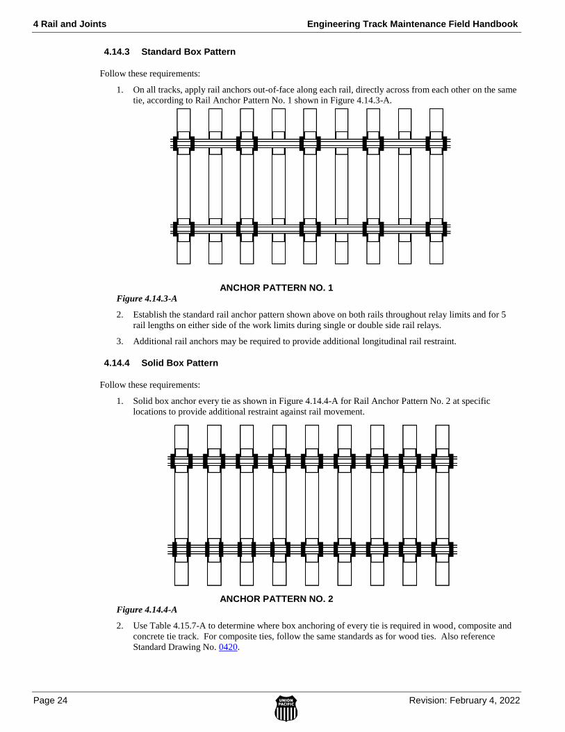
4 Rail and Joints Engineering Track Maintenance Field Handbook
Page 24 Revision: February 4, 2022
4.14.3 Standard Box Pattern
Follow these requirements:
1. On all tracks, apply rail anchors out-of-face along each rail, directly across from each other on the same
tie, according to Rail Anchor Pattern No. 1 shown in Figure 4.14.3-A.
ANCHOR PATTERN NO. 1 Figure 4.14.3-A
2. Establish the standard rail anchor pattern shown above on both rails throughout relay limits and for 5
rail lengths on either side of the work limits during single or double side rail relays.
3. Additional rail anchors may be required to provide additional longitudinal rail restraint.
4.14.4 Solid Box Pattern
Follow these requirements:
1. Solid box anchor every tie as shown in Figure 4.14.4-A for Rail Anchor Pattern No. 2 at specific
locations to provide additional restraint against rail movement.
ANCHOR PATTERN NO. 2 Figure 4.14.4-A
2. Use Table 4.15.7-A to determine where box anchoring of every tie is required in wood, composite and
concrete tie track. For composite ties, follow the same standards as for wood ties. Also reference
Standard Drawing No. 0420.

Engineering Track Maintenance Field Handbook 4 Rail and Joints
Revision: February 4, 2022 Page 25
Location Rail Type Requirement
Turnouts (Concrete and Wood Ties) CWR All switch ties and 120 ties in all directions
Turnouts (Wood Ties Only) Jointed All switch ties and 48 ties in all directions
Crossing Frogs (Concrete and Wood Ties)
CWR or Jointed 120 ties in all directions
Hot Box / Dragging Equipment Detectors (Wood Ties Only)
CWR or Jointed 120 ties in each direction
All Permanent and Insulated Joints (Wood Ties Only)
CWR 120 ties in each direction
Expansion Joints (Concrete and Wood Ties)
CWR or Jointed 120 ties in each direction
Lines with traffic of 95 MGT or more annually (Wood Ties Only)
CWR Every tie
Open-Deck Bridges (Concrete and Wood Ties)
CWR All bridge ties and 120 ties in each direction
EXCEPTION: See Standard Drawing 0461 for steel spans.
Ballast Deck Bridges and Passenger Platforms (Wood Ties Only)
CWR Anchor with same pattern as rail leading into the facility
Road Crossings (Wood Ties Only) CWR or Jointed Every tie through the crossing limits
Table 4.14.4-A
4.14.5 Bridge Pattern
Follow these bridge anchoring requirements:
1. Ballast deck bridges should be anchored according to Standard Drawing No. 0421.
Anchor ballast deck bridges with the same pattern as the rail leading onto the bridge.
2. Open deck bridges should be anchored according to Standard Drawing No. 0421.
Solid box anchor every bridge tie across open-deck bridges and 120 ties each side of bridge headwalls.
Exception: For steel spans more than 125 feet long:
– Box anchor all bridge ties in at least one-third of the total number of panels of the
bridge at the fixed end of the span.
4.14.6 Turnout Pattern
Follow these turnout anchoring requirements:
1. Box anchor all switch ties to the extent that the anchors will not interfere with the proper operation of
the turnout. Refer to Standard Drawing No. 0420.
2. Anchor the switch point and stock rail at the heel block as follows:
a. Locate the heel blocks on the mainline and turnout sides, refer to Figure 4.14.6-A.
b. Anchor the switch point and stock rail on the mainline side as follows:
i. Begin by installing two anchors next to one tie and two additional anchors next to the
other tie in a crib.
NOTE: Solid anchoring of a single crib will require 6-8 anchors.
ii. Continue to apply anchors to fill in area between the first four anchors installed.
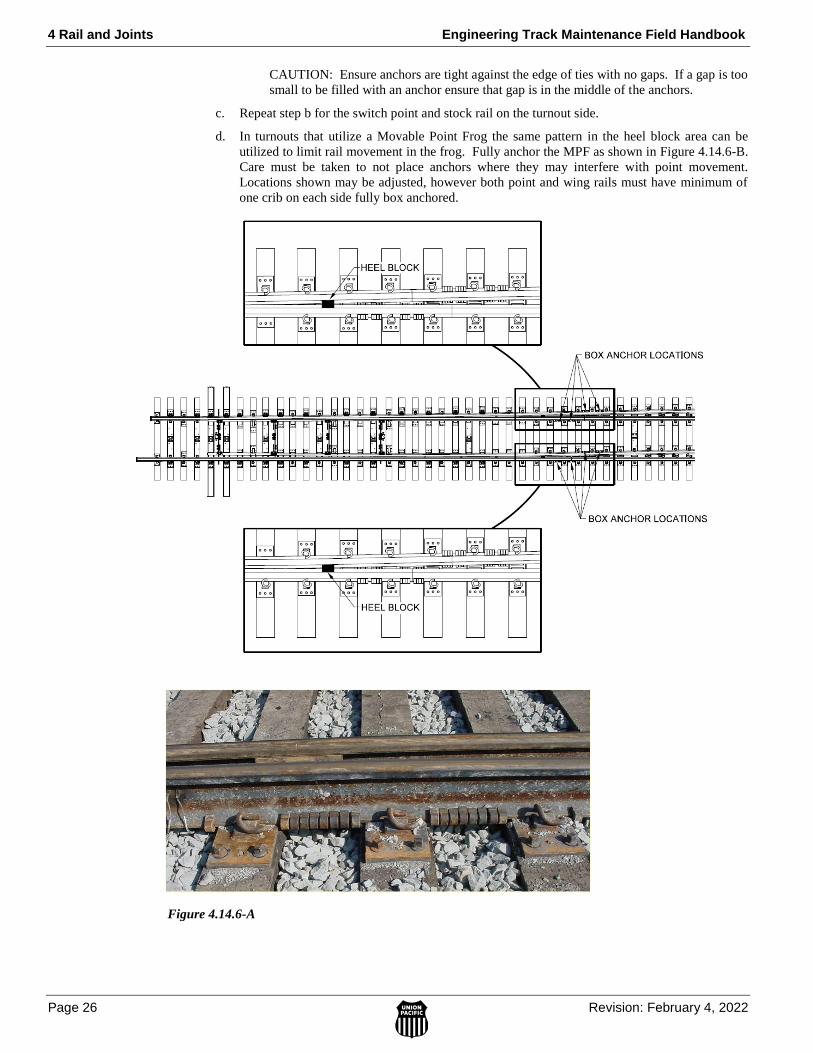
4 Rail and Joints Engineering Track Maintenance Field Handbook
Page 26 Revision: February 4, 2022
CAUTION: Ensure anchors are tight against the edge of ties with no gaps. If a gap is too
small to be filled with an anchor ensure that gap is in the middle of the anchors.
c. Repeat step b for the switch point and stock rail on the turnout side.
d. In turnouts that utilize a Movable Point Frog the same pattern in the heel block area can be
utilized to limit rail movement in the frog. Fully anchor the MPF as shown in Figure 4.14.6-B.
Care must be taken to not place anchors where they may interfere with point movement.
Locations shown may be adjusted, however both point and wing rails must have minimum of
one crib on each side fully box anchored.
Figure 4.14.6-A
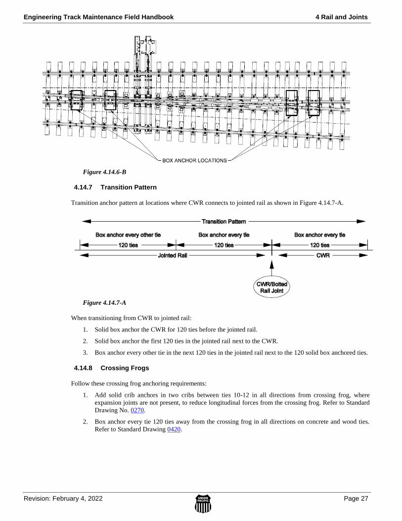
Engineering Track Maintenance Field Handbook 4 Rail and Joints
Revision: February 4, 2022 Page 27
Figure 4.14.6-B
4.14.7 Transition Pattern
Transition anchor pattern at locations where CWR connects to jointed rail as shown in Figure 4.14.7-A.
Figure 4.14.7-A
When transitioning from CWR to jointed rail:
1. Solid box anchor the CWR for 120 ties before the jointed rail.
2. Solid box anchor the first 120 ties in the jointed rail next to the CWR.
3. Box anchor every other tie in the next 120 ties in the jointed rail next to the 120 solid box anchored ties.
4.14.8 Crossing Frogs
Follow these crossing frog anchoring requirements:
1. Add solid crib anchors in two cribs between ties 10-12 in all directions from crossing frog, where
expansion joints are not present, to reduce longitudinal forces from the crossing frog. Refer to Standard
Drawing No. 0270.
2. Box anchor every tie 120 ties away from the crossing frog in all directions on concrete and wood ties.
Refer to Standard Drawing 0420.

4 Rail and Joints Engineering Track Maintenance Field Handbook
Page 28 Revision: February 4, 2022
Engineering Track Maintenance Field Handbook 4 Rail and Joints
Revision: February 4, 2022 Page 29
4 Rail and Joints Engineering Track Maintenance Field Handbook
Page 30 Revision: February 4, 2022

Engineering Track Maintenance Field Handbook 4 Rail and Joints
Revision: February 4, 2022 Page 31
4 Rail and Joints Engineering Track Maintenance Field Handbook
Page 32 Revision: February 4, 2022

Engineering Track Maintenance Field Handbook 4 Rail and Joints
Revision: February 4, 2022 Page 33
4 Rail and Joints Engineering Track Maintenance Field Handbook
Page 34 Revision: February 4, 2022

Engineering Track Maintenance Field Handbook 4 Rail and Joints
Revision: February 4, 2022 Page 35
4 Rail and Joints Engineering Track Maintenance Field Handbook
Page 36 Revision: February 4, 2022
Engineering Track Maintenance Field Handbook 4 Rail and Joints
Revision: February 4, 2022 Page 37
4 Rail and Joints Engineering Track Maintenance Field Handbook
Page 38 Revision: February 4, 2022

Engineering Track Maintenance Field Handbook 4 Rail and Joints
Revision: February 4, 2022 Page 39

4 Rail and Joints Engineering Track Maintenance Field Handbook
Page 40 Revision: February 4, 2022
Engineering Track Maintenance Field Handbook 4 Rail and Joints
Revision: February 4, 2022 Page 41
4 Rail and Joints Engineering Track Maintenance Field Handbook
Page 42 Revision: February 4, 2022
Engineering Track Maintenance Field Handbook 4 Rail and Joints
Revision: February 4, 2022 Page 43
4 Rail and Joints Engineering Track Maintenance Field Handbook
Page 44 Revision: February 4, 2022

Engineering Track Maintenance Field Handbook 4 Rail and Joints
Revision: February 4, 2022 Page 45
4 Rail and Joints Engineering Track Maintenance Field Handbook
Page 46 Revision: February 4, 2022

Engineering Track Maintenance Field Handbook 4 Rail and Joints
Revision: February 4, 2022 Page 47
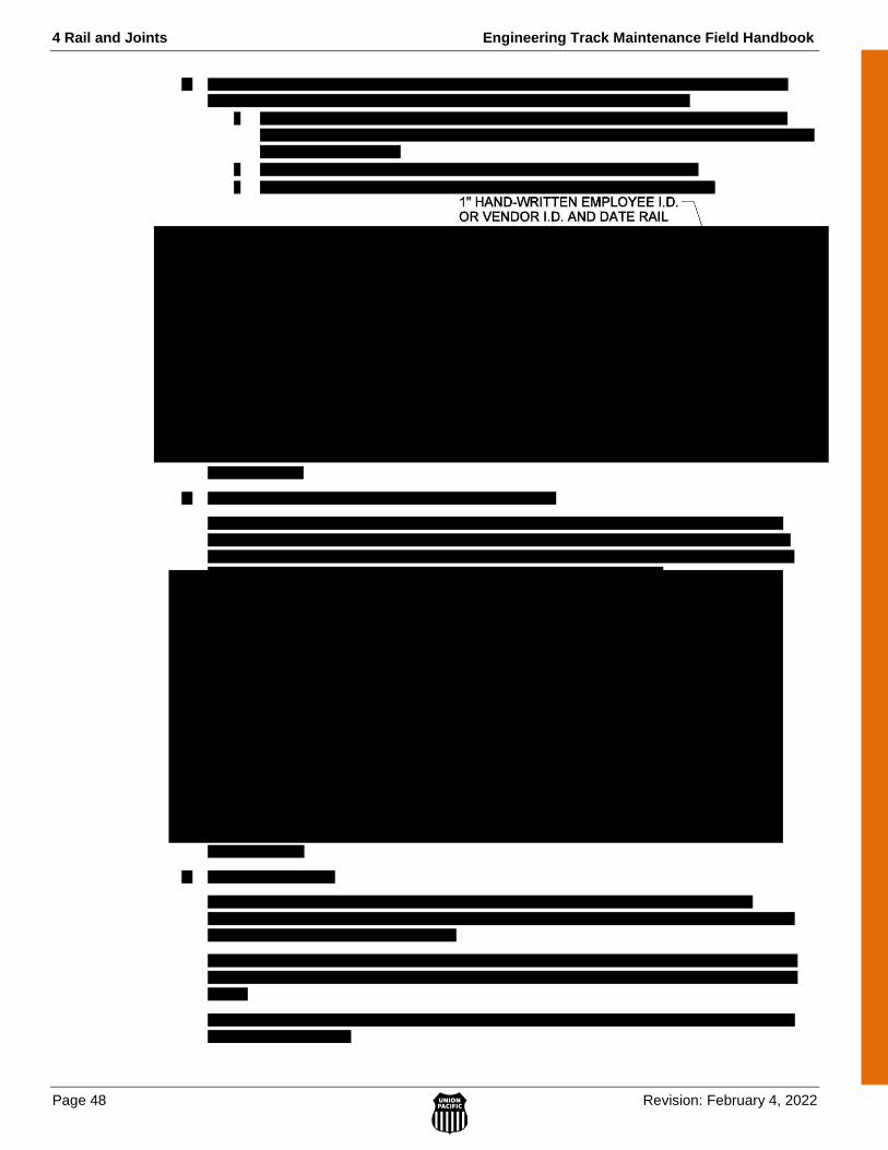
4 Rail and Joints Engineering Track Maintenance Field Handbook
Page 48 Revision: February 4, 2022
Engineering Track Maintenance Field Handbook 4 Rail and Joints
Revision: February 4, 2022 Page 49
4 Rail and Joints Engineering Track Maintenance Field Handbook
Page 50 Revision: February 4, 2022
Engineering Track Maintenance Field Handbook 4 Rail and Joints
Revision: February 4, 2022 Page 51
4.18 Rail Handling
When lifting rail:
1. Center mark rail before lifting to balance the load.
2. Use approved rail tongs or grapple buckets when handling rail 60 feet or less.
3. Use a spreader bar when handling rail more than 60 feet.
Engineering Track Maintenance Field Handbook 5 Turnouts
Revision: September 7, 2021 Page 1
5.0 TU
RN
OU
TS
5 TURNOUTS
5.1 Turnout Identification ................................................................................................................................ 3
5.1.1 General ..................................................................................................................................... 3
5.1.2 Turnout Construction ............................................................................................................... 5
5.5 Frogs .......................................................................................................................................................... 18
5.5.1 Identification of Frogs by Number ........................................................................................... 18
5.5.2 Frog Types ............................................................................................................................... 19
A. Railbound Manganese Frog (RBM) ..................................................................................... 19
B. Rigid Bolted Frog (All Rail) ................................................................................................. 19
C. Spring Frog ........................................................................................................................... 19
D. Solid Manganese Self-Guarded Frog (SMSG) ..................................................................... 20
E. Movable Point Frog (MPF) .................................................................................................. 20
F. Jump Frog ............................................................................................................................. 20
G. Crossing Frog (Diamond) ..................................................................................................... 21
5 Turnouts Engineering Track Maintenance Field Handbook
Page 2 Revision: September 7, 2021
5.5.5 Frog Guard Rail Size and Length ............................................................................................. 27
5.5.6 Frog / Diamond Bolts ............................................................................................................... 27
5.7 Derails – Permanent & Portable ................................................................................................................. 38
5.7.1 Permanent Derail Requirements ............................................................................................... 38
5.7.2 Use of Portable Derails............................................................................................................. 38
5.7.3 Placement of Derails on Controlled Sidings............................................................................. 38
5.9 Clearance Point .......................................................................................................................................... 39
Engineering Track Maintenance Field Handbook 5 Turnouts
Revision: September 7, 2021 Page 3
5.0 TU
RN
OU
TS
5.1 Turnout Identification
5.1.1 General
The following are general guidelines for turnout identification:
1. Identify turnouts by their frog number. Refer to Standard Drawing No. 0080 for recommended turnout
applications.
2. Determine if a turnout is a left- or right-hand turnout by determining the direction of the diverging
track. To do this, stand in the track ahead of the switch and face the frog.
If the diverging track is on the left, it is a left-hand turnout. See Figure 5.1.1-A.
Figure 5.1.1-A
If the diverging track is on the right, it is a right-hand turnout. See Figure 5.1.1-B.
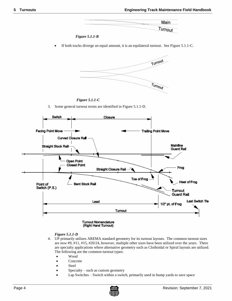
5 Turnouts Engineering Track Maintenance Field Handbook
Page 4 Revision: September 7, 2021
Figure 5.1.1-B
If both tracks diverge an equal amount, it is an equilateral turnout. See Figure 5.1.1-C.
Figure 5.1.1-C
3. Some general turnout terms are identified in Figure 5.1.1-D.
Figure 5.1.1-D
4. UP primarily utilizes AREMA standard geometry for its turnout layouts. The common turnout sizes
are now #9, #11, #15, #20/24, however, multiple other sizes have been utilized over the years. There
are specialty applications where alternative geometry such as Clothoidal or Spiral layouts are utilized.
The following are the common turnout types:
Wood
Concrete
Steel
Specialty – such as custom geometry
Lap Switches – Switch within a switch, primarily used in hump yards to save space

Engineering Track Maintenance Field Handbook 5 Turnouts
Revision: September 7, 2021 Page 5
5.0 TU
RN
OU
TS
5.1.2 Turnout Construction
Follow these requirements for constructing turnouts:
1. Construct turnouts as prescribed in the UPRR Track Standards.
2. Construct turnouts using head hardened rail. Intermediate strength head hardened rail may be used
where authorized by UPRR standards.
3. Do not use rails of different sizes in the same turnout except in case of emergency where transition
rails are utilized.
4. Spike turnouts according to Standard Drawing No. 0417.
5. Box anchor all switch ties to the extent that the anchors will not interfere with the proper operation of
the turnout. Refer to Standard Drawing No. 0420 and Section 4.17 Rail Anchors for further
information.
5 Turnouts Engineering Track Maintenance Field Handbook
Page 6 Revision: September 7, 2021
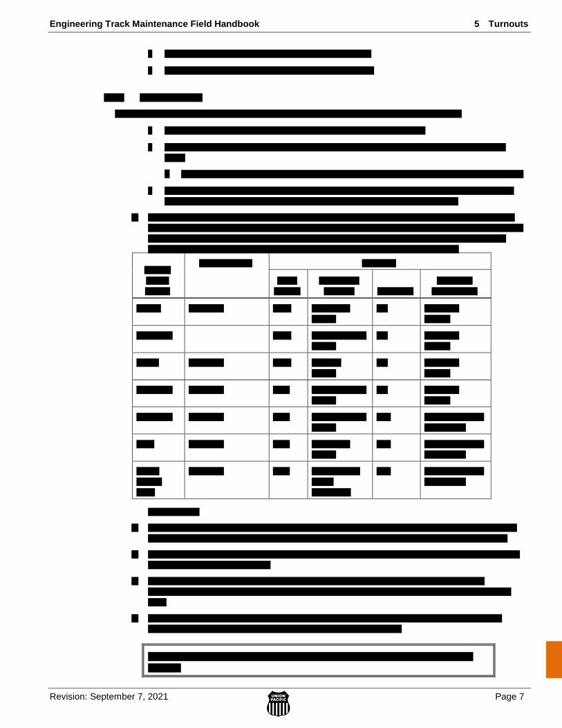
Engineering Track Maintenance Field Handbook 5 Turnouts
Revision: September 7, 2021 Page 7
5.0 TU
RN
OU
TS
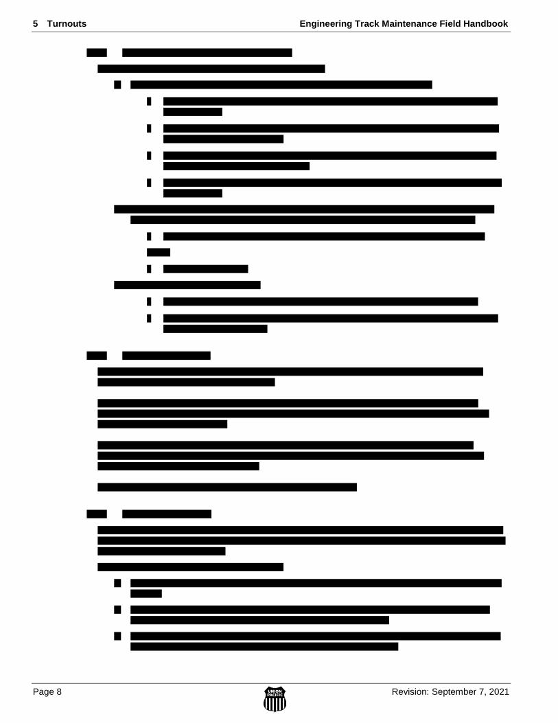
5 Turnouts Engineering Track Maintenance Field Handbook
Page 8 Revision: September 7, 2021
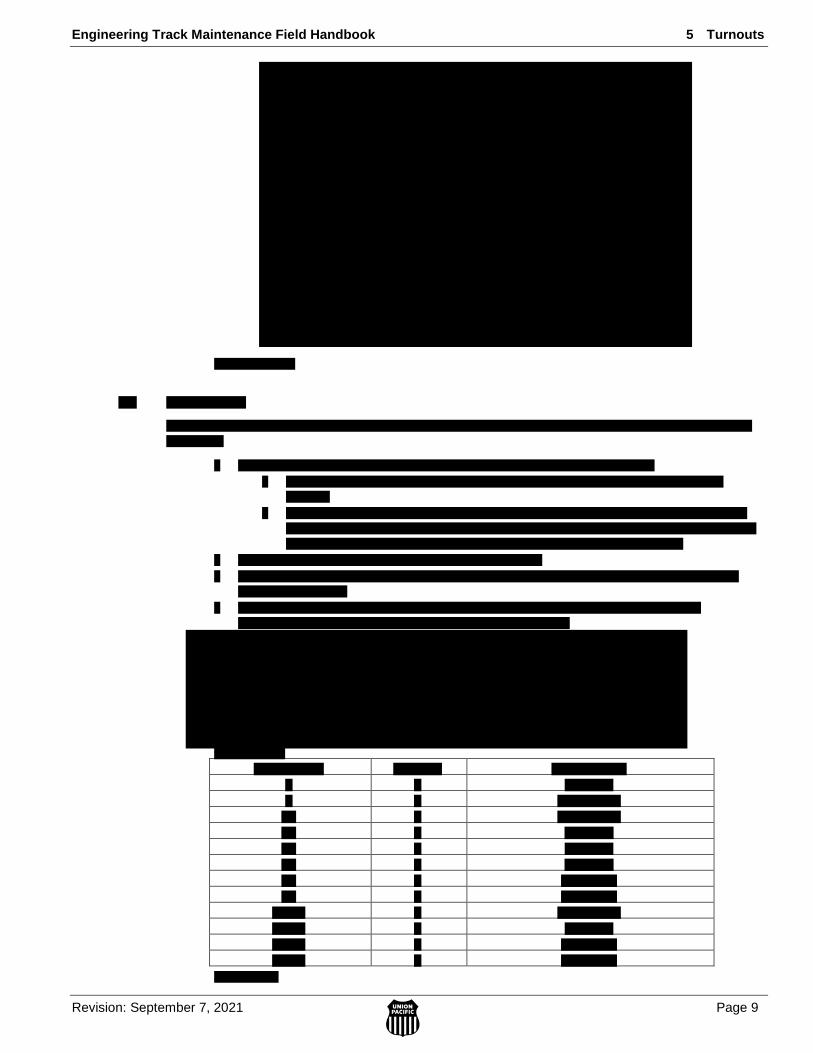
Engineering Track Maintenance Field Handbook 5 Turnouts
Revision: September 7, 2021 Page 9
5.0 TU
RN
OU
TS
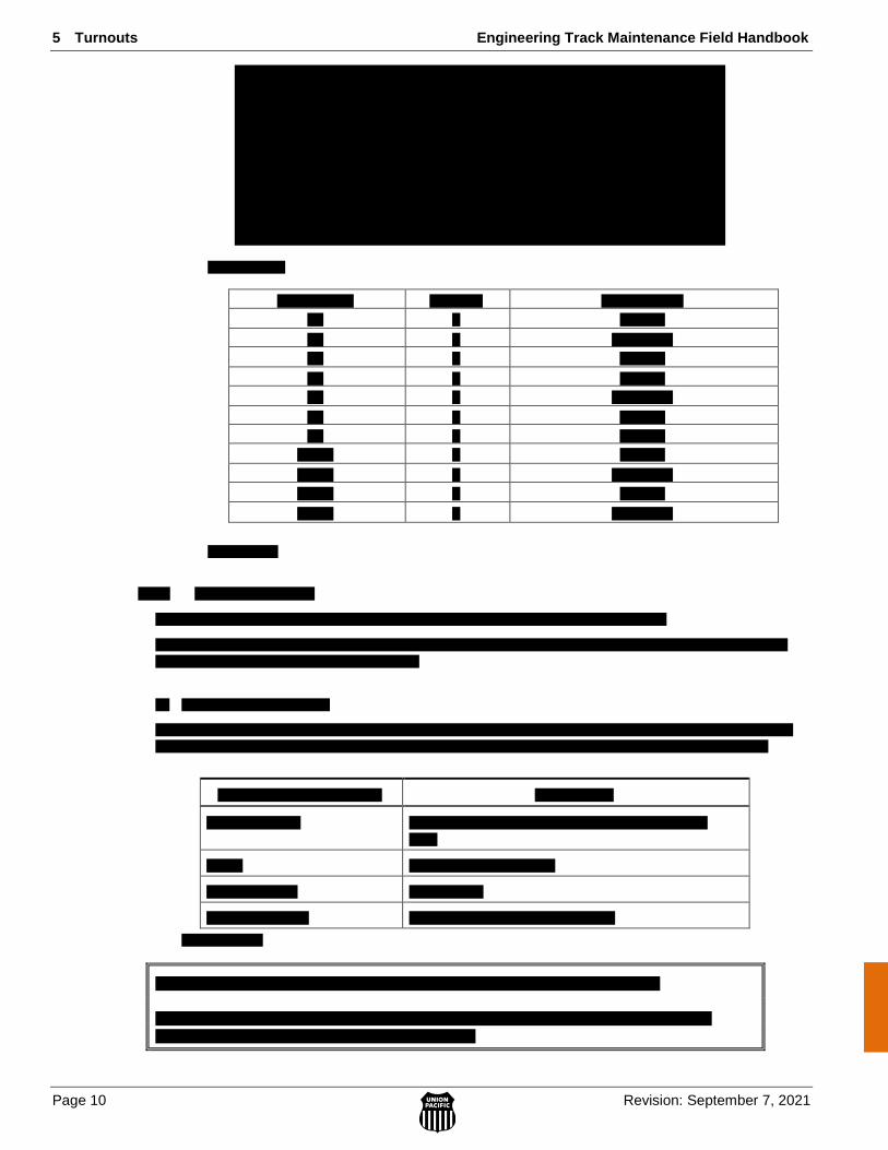
5 Turnouts Engineering Track Maintenance Field Handbook
Page 10 Revision: September 7, 2021
Engineering Track Maintenance Field Handbook 5 Turnouts
Revision: September 7, 2021 Page 11
5.0 TU
RN
OU
TS
5 Turnouts Engineering Track Maintenance Field Handbook
Page 12 Revision: September 7, 2021
Engineering Track Maintenance Field Handbook 5 Turnouts
Revision: September 7, 2021 Page 13
5.0 TU
RN
OU
TS

5 Turnouts Engineering Track Maintenance Field Handbook
Page 14 Revision: September 7, 2021
Engineering Track Maintenance Field Handbook 5 Turnouts
Revision: September 7, 2021 Page 15
5.0 TU
RN
OU
TS
5 Turnouts Engineering Track Maintenance Field Handbook
Page 16 Revision: September 7, 2021
Engineering Track Maintenance Field Handbook 5 Turnouts
Revision: September 7, 2021 Page 17
5.0 TU
RN
OU
TS
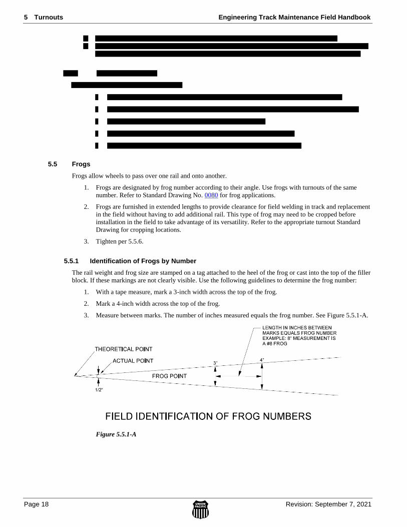
5 Turnouts Engineering Track Maintenance Field Handbook
Page 18 Revision: September 7, 2021
5.5 Frogs
Frogs allow wheels to pass over one rail and onto another.
1. Frogs are designated by frog number according to their angle. Use frogs with turnouts of the same
number. Refer to Standard Drawing No. 0080 for frog applications.
2. Frogs are furnished in extended lengths to provide clearance for field welding in track and replacement
in the field without having to add additional rail. This type of frog may need to be cropped before
installation in the field to take advantage of its versatility. Refer to the appropriate turnout Standard
Drawing for cropping locations.
3. Tighten per 5.5.6.
5.5.1 Identification of Frogs by Number
The rail weight and frog size are stamped on a tag attached to the heel of the frog or cast into the top of the filler
block. If these markings are not clearly visible. Use the following guidelines to determine the frog number:
1. With a tape measure, mark a 3-inch width across the top of the frog.
2. Mark a 4-inch width across the top of the frog.
3. Measure between marks. The number of inches measured equals the frog number. See Figure 5.5.1-A.
Figure 5.5.1-A
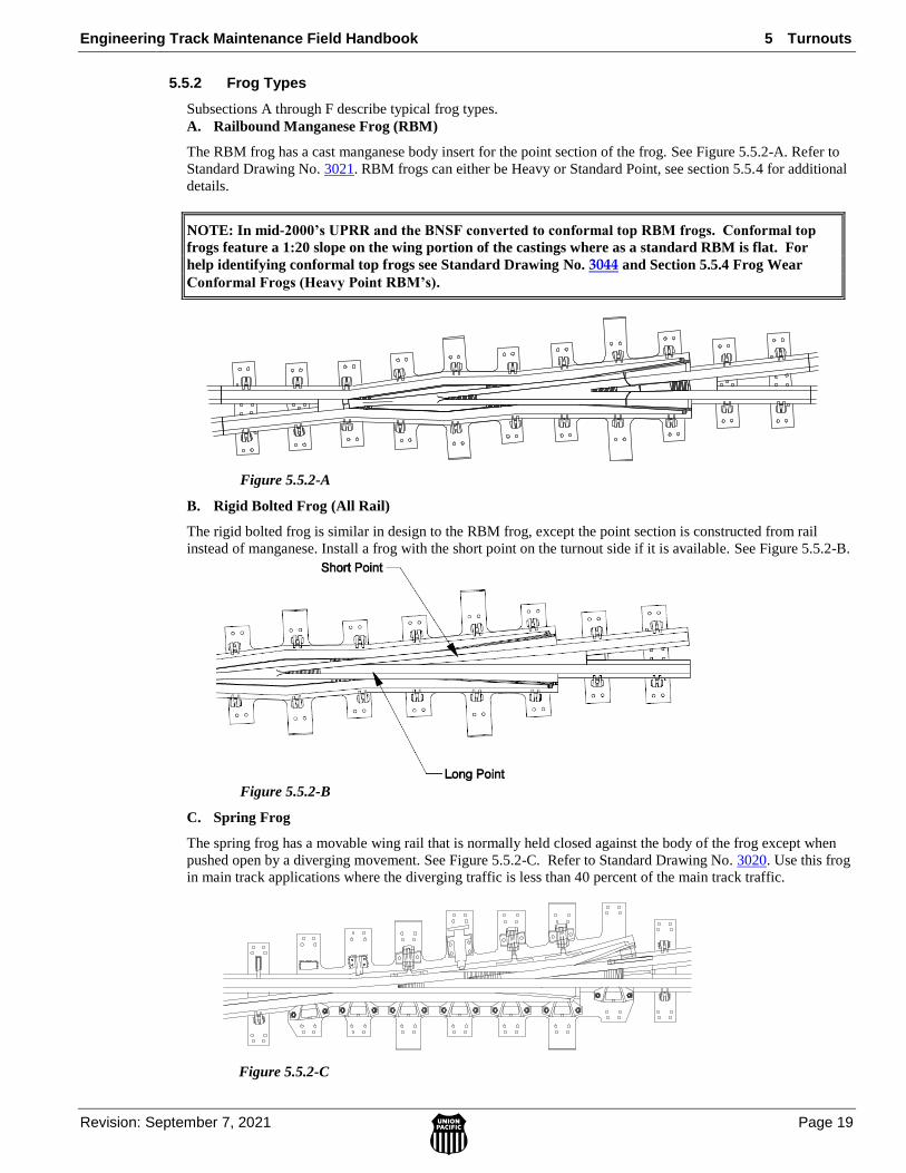
Engineering Track Maintenance Field Handbook 5 Turnouts
Revision: September 7, 2021 Page 19
5.0 TU
RN
OU
TS
5.5.2 Frog Types
Subsections A through F describe typical frog types.
A. Railbound Manganese Frog (RBM)
The RBM frog has a cast manganese body insert for the point section of the frog. See Figure 5.5.2-A. Refer to
Standard Drawing No. 3021. RBM frogs can either be Heavy or Standard Point, see section 5.5.4 for additional
details.
NOTE: In mid-2000’s UPRR and the BNSF converted to conformal top RBM frogs. Conformal top
frogs feature a 1:20 slope on the wing portion of the castings where as a standard RBM is flat. For
help identifying conformal top frogs see Standard Drawing No. 3044 and Section 5.5.4 Frog Wear
Conformal Frogs (Heavy Point RBM’s).
Figure 5.5.2-A
B. Rigid Bolted Frog (All Rail)
The rigid bolted frog is similar in design to the RBM frog, except the point section is constructed from rail
instead of manganese. Install a frog with the short point on the turnout side if it is available. See Figure 5.5.2-B.
Figure 5.5.2-B
C. Spring Frog
The spring frog has a movable wing rail that is normally held closed against the body of the frog except when
pushed open by a diverging movement. See Figure 5.5.2-C. Refer to Standard Drawing No. 3020. Use this frog
in main track applications where the diverging traffic is less than 40 percent of the main track traffic.
Figure 5.5.2-C

5 Turnouts Engineering Track Maintenance Field Handbook
Page 20 Revision: September 7, 2021
D. Solid Manganese Self-Guarded Frog (SMSG)
The SMSG frog has a body cast in one piece from manganese steel. A raised guard cast into the body protects
the frog point from passing wheels, making the installation of a guard rail on the opposite rail unnecessary. See
Figure 5.5.2-D. Refer to Standard Drawing No. 3021.
Use this frog in yard and industry applications where the track speed does not exceed 20 mph.
Figure 5.5.2-D
Follow these special guidelines for SMSG frogs:
1. If building the frog point under traffic, build the guarding face before the frog point.
2. Install guard rails as an option in cases where additional guarding may be required, such as curved
switches.
E. Movable Point Frog (MPF)
The MPF is equipped with a point that is movable in the same manner as the switch points. See Figure 5.5.2-E.
Refer to Standard Drawing No. 3022. This frog is used in heavy tonnage on #20 and larger, high-speed main
track where the traffic on the straight and diverging side of the turnout is comparable.
Figure 5.5.2-E
F. Jump Frog
The jump frog features a continuous mainline rail and a flange bearing run on the turnout side. This frog can be
utilized in situations where traffic through the diverging route is minimal such as maintenance of way tracks or
small industry tracks. Speed is limited on the turnout run to 10 MPH.
Figure 5.5.2-F

Engineering Track Maintenance Field Handbook 5 Turnouts
Revision: September 7, 2021 Page 21
5.0 TU
RN
OU
TS
5 Turnouts Engineering Track Maintenance Field Handbook
Page 22 Revision: September 7, 2021
Engineering Track Maintenance Field Handbook 5 Turnouts
Revision: September 7, 2021 Page 23
5.0 TU
RN
OU
TS
5 Turnouts Engineering Track Maintenance Field Handbook
Page 24 Revision: September 7, 2021
Engineering Track Maintenance Field Handbook 5 Turnouts
Revision: September 7, 2021 Page 25
5.0 TU
RN
OU
TS

5 Turnouts Engineering Track Maintenance Field Handbook
Page 26 Revision: September 7, 2021
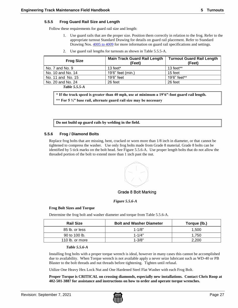
Engineering Track Maintenance Field Handbook 5 Turnouts
Revision: September 7, 2021 Page 27
5.0 TU
RN
OU
TS
5.5.5 Frog Guard Rail Size and Length
Follow these requirements for guard rail size and length:
1. Use guard rails that are the proper size. Position them correctly in relation to the frog. Refer to the
appropriate turnout Standard Drawing for details on guard rail placement. Refer to Standard
Drawing Nos. 4005 to 4009 for more information on guard rail specifications and settings.
2. Use guard rail lengths for turnouts as shown in Table 5.5.5-A.
Frog Size Main Track Guard Rail Length
(Feet) Turnout Guard Rail Length
(Feet)
No. 7 and No. 9 13 feet* 13 feet**
No. 10 and No. 14 19’6” feet (min.) 15 feet
No. 11 and No. 15 19’6” feet 19’6” feet**
No. 20 and No. 24 26 feet 26 feet
Table 5.5.5-A
* If the track speed is greater than 40 mph, use at minimum a 19’6”-foot guard rail length.
** For 5 ½” base rail, alternate guard rail size may be necessary
Do not build up guard rails by welding in the field.
5.5.6 Frog / Diamond Bolts
Replace frog bolts that are missing, bent, cracked or worn more than 1/8 inch in diameter, or that cannot be
tightened to compress the washer. Use only frog bolts made from Grade 8 material. Grade 8 bolts can be
identified by 5 tick marks on the bolt head. See Figure 5.5.6-A. Use proper length bolts that do not allow the
threaded portion of the bolt to extend more than 1 inch past the nut.
Figure 5.5.6-A
Frog Bolt Sizes and Torque
Determine the frog bolt and washer diameter and torque from Table 5.5.6-A.
Rail Size Bolt and Washer Diameter Torque (lb.)
85 lb. or less 1-1/8" 1,500
90 to 100 lb. 1-1/4" 1,750
110 lb. or more 1-3/8" 2,200
Table 5.5.6-A
Installing frog bolts with a proper torque wrench is ideal, however in many cases this cannot be accomplished
due to availability. When Torque wrench is not available apply a never seize lubricant such as WD-40 or PB
Blaster to the bolt threads and nut threads before tightening. Tighten until refusal.
Utilize One Heavy Hex Lock Nut and One Hardened Steel Flat Washer with each Frog Bolt.
Proper Torque is CRITICAL on crossing diamonds, especially new installations. Contact Chris Roop at
402-501-3887 for assistance and instructions on how to order and operate torque wrenches.

5 Turnouts Engineering Track Maintenance Field Handbook
Page 28 Revision: September 7, 2021
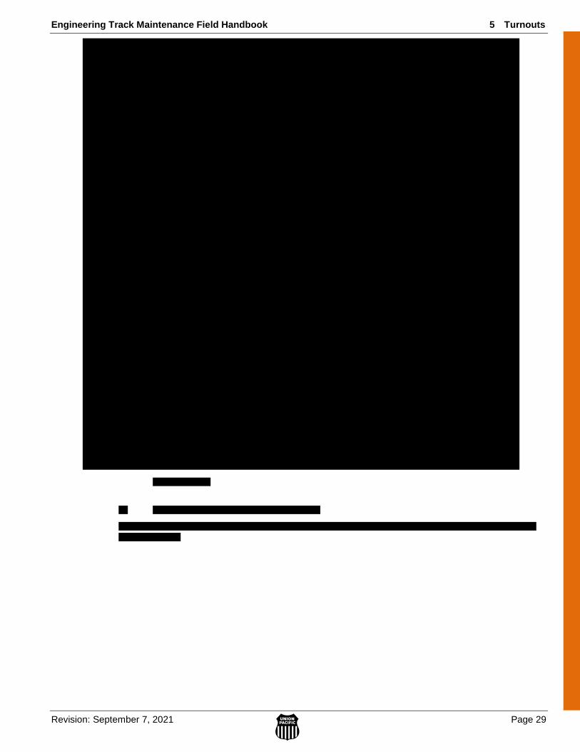
Engineering Track Maintenance Field Handbook 5 Turnouts
Revision: September 7, 2021 Page 29
5.0 TU
RN
OU
TS
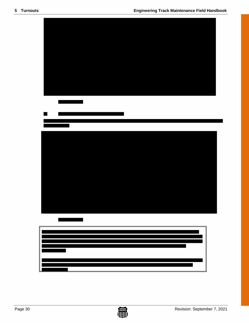
5 Turnouts Engineering Track Maintenance Field Handbook
Page 30 Revision: September 7, 2021
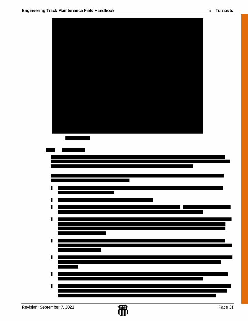
Engineering Track Maintenance Field Handbook 5 Turnouts
Revision: September 7, 2021 Page 31
5.0 TU
RN
OU
TS
5 Turnouts Engineering Track Maintenance Field Handbook
Page 32 Revision: September 7, 2021
Engineering Track Maintenance Field Handbook 5 Turnouts
Revision: September 7, 2021 Page 33
5.0 TU
RN
OU
TS
5 Turnouts Engineering Track Maintenance Field Handbook
Page 34 Revision: September 7, 2021
Engineering Track Maintenance Field Handbook 5 Turnouts
Revision: September 7, 2021 Page 35
5.0 TU
RN
OU
TS
5 Turnouts Engineering Track Maintenance Field Handbook
Page 36 Revision: September 7, 2021

Engineering Track Maintenance Field Handbook 5 Turnouts
Revision: September 7, 2021 Page 37
5.0 TU
RN
OU
TS
5 Turnouts Engineering Track Maintenance Field Handbook
Page 38 Revision: September 7, 2021
5.7 Derails – Permanent & Portable
5.7.1 Permanent Derail Requirements
Inspect and evaluate the territory for correct placement of required permanent derails. Refer to Standard
Drawing Nos. 2000 to 2022 for details and instructions on placement. Refer to the WPD on Derail Installation
for installation instructions.
All mainiline and siding routes require protection by permanent derails on all connecting industrial or
auxiliary tracks.
Ensure derails are installed on solid ties and secure with lag screws whenever possible.
Whenever possible avoid installing in a curve. If no other option is available install permanent derail
on the outside rail of curves (high side). When necessary to derail towards the inside rail install a type
2 or 3 derail.
Permanent derails installed on Siding or CNRT track types may not be removed unless approved by the Vice
President Engineering.
Leave derails lined and locked in the derailing position except when movement over is expected and authorized.
5.7.2 Use of Portable Derails
Portable derails are to be used only for temporary applications where permanent derails cannot be installed.
Portable derails must be applied per the procedure below and UPRR Standard Drawing No. 2003.
Portable derails may not be used to protect tracks with grade greater than 0.25% ascending away (uphill).
Calculate grade by using a 32’ stringline and string level. If one end of your level stringline is on the top of the
rail and the other end is over one inch (1”) off the rail at 32’, then the track has a grade greater than 0.25%.
Portable derails must be stored inside a locked tool box or storage box on vehicles or inside of a locked
storage facility. If no lockable tool box is available on a vehicle for storing portable derails, they must be
chained using a grade eight chain and lock or otherwise secured and locked to the vehicle.
When UPRR Standards require a permanent derail and one does not exist where cars are being stored, a
portable derail may be used only if the grade is flat or descending away (downhill) from the protected track.
Portable derails may only be installed for a maximum of 30 days. After 30 days, the proper derail must be
installed, or the cars must be removed and the track removed from service.
Any portable derails that are struck by equipment must be discarded and replaced.
5.7.3 Placement of Derails on Controlled Sidings
Derails may be required on controlled sidings in certain situations such as long term car storage. Prior to
placing derails in a controlled siding it is recommended that the Manager of Signal Maintenance be contacted to
review the requirements.
Prior to installing derail(s), Manager Signal Maintenance will contact the Manager Signal Design to
determine proper method of disabling signals governing movement through the siding. Asst.
Manager Signal Design will then confirm the disabling procedure in a lotus note to both the MSM
and the Sr Manager Signal Operations. After the disabling procedures have been confirmed, signal
personnel will disable the signals.
The MSM will request Signal Operations Control (SOC) to open a ticket that will remain in hold
status until the signals are tested and returned to service.
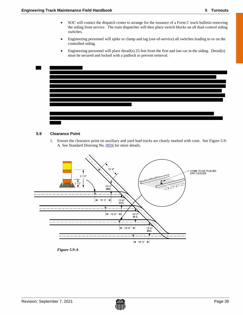
Engineering Track Maintenance Field Handbook 5 Turnouts
Revision: September 7, 2021 Page 39
5.0 TU
RN
OU
TS
SOC will contact the dispatch center to arrange for the issuance of a Form C track bulletin removing
the siding from service. The train dispatcher will then place switch blocks on all dual-control siding
switches.
Engineering personnel will spike or clamp and tag (out-of-service) all switches leading to or on the
controlled siding.
Engineering personnel will place derail(s) 25 feet from the first and last car in the siding. Derail(s)
must be secured and locked with a padlock to prevent removal.
5.9 Clearance Point
1. Ensure the clearance point on auxiliary and yard lead tracks are clearly marked with cone. See Figure 5.9-
A. See Standard Drawing No. 0026 for more details.
Figure 5.9-A
5 Turnouts Engineering Track Maintenance Field Handbook
Page 40 Revision: September 7, 2021
Engineering Track Maintenance Field Handbook 6 Right of Way and Other Facilities
Revision: July 12, 2021 Page 1
6.0 RIG
HT
-OF
-WA
Y
& F
AC
ILIT
IES
6 RIGHT OF WAY AND OTHER FACILITIES
6.1 Area of No Obstruction .............................................................................................................................. 2
4
6.3 Roadway Signs ........................................................................................................................................... 4
6.3.1 General......................................................................................................................................... 4
6.3.2 Whistle Signs ............................................................................................................................... 4
6.3.3 Standard Highway Crossing Signs (Crossbucks) ......................................................................... 5
6.3.4 Clearance Warning Signs............................................................................................................. 5
6.3.5 End of Track Sign ........................................................................................................................ 5
6.4 Roadways ................................................................................................................................................... 6
6.4.1 Grade Crossings ........................................................................................................................... 6
A. General ................................................................................................................................. 6
B. Crossing Warning Devices (Passive/Active) ........................................................................ 6
C. Crossing Drainage ................................................................................................................ 6
6.4.2 Right of Way Roads ..................................................................................................................... 7
6.6 Bridges ....................................................................................................................................................... 7
6.6.1 Bridge Identification .................................................................................................................... 7
6.7 Fiber Optics ................................................................................................................................................ 9
6.8 PTC – Critical Asset Change Management ................................................................................................ 12

6 Right of Way and Other Facilities Engineering Track Maintenance Field Handbook
Page 2 Revision: July 12, 2021
6.1 Area of No Obstruction
The Area of No Obstruction refers to the area around the track where Engineering Personnel need to avoid
placing material, equipment etc. as it may be struck by a passing train or equipment during normal movement.
When unloading material such as ballast, rail or OTM it should not be left in this area during normal train
operations. Care should also be taken to secure material that may move to avoid it being able to enter this area
unmonitored. When material is left in this area movement over it should be done at restricted speed and
monitored. This Area of No Obstruction applies specifically to material, equipment left in place and does not
supersede the standard minimum operating clearances or on track safety requirements.
Figure 6.1-A

Engineering Track Maintenance Field Handbook 6 Right of Way and Other Facilities
Revision: July 12, 2021 Page 3
6.0 RIG
HT
-OF
-WA
Y
& F
AC
ILIT
IES
6 Right of Way and Other Facilities Engineering Track Maintenance Field Handbook
Page 4 Revision: July 12, 2021
6.3 Roadway Signs
Roadway signs are an important means to provide information to employees and others. They are a vital part of
the safety of the railroad, providing instructions and visual reminders of warnings. They also serve as reference
markers for structures and locations. As such, their use and maintenance should not be overlooked.
6.3.1 General
Employees must place and maintain roadway signs where required. Keep roadway signs erect, plumb, and
legible. Replace all defaced signs as soon as practicable. Any deviation from the standards must have Vice
President Engineering approval.
NOTE: Refer to Engineering Track Standard Drawing Nos. 0501 through 0599 for proper size and placement of all approved railroad signs. When sign is installed, write date on back of sign in MM/YY format. This is for warranty purposes.
6.3.2 Whistle Signs
Whistle signs are used to inform an engineer that the train is approaching a road crossing. Federal law requires
the engineer to sound a whistle cadence at identified crossings unless designated as a Quiet Zone. Place per
Standard Drawing No. 0543 or Standard Drawing No. 0544 for Quiet Zone Crossings. These locations are
designated in the DOT Crossing Inventory.
Engineering Track Maintenance Field Handbook 6 Right of Way and Other Facilities
Revision: July 12, 2021 Page 5
6.0 RIG
HT
-OF
-WA
Y
& F
AC
ILIT
IES
6.3.3 Standard Highway Crossing Signs (Crossbucks)
Standard highway crossing signs (crossbucks) must be placed on the right side of each approach of all public
road crossings without signalized protection.
The initial installation of yield or stop signs at these crossings is negotiated by the Engineering Department’s
Industry and Public Projects Group. Union Pacific maintains / replaces these signs after they are installed.
Follow these requirements for installation and inspection:
Place per Standard Drawing No. 0519
Follow inspection requirements for crossing signs as detailed in M/W Rule 53.1.1 Road Crossing
Condition.
Follow these requirements for replacement of existing signs:
To determine the current sign type and standard for existing yield or stop sign installations for any
particular at-grade crossing location(s), utilize the UPRR website: MyUP> Public Projects> Facility
Reporting> DOT Road Crossing Reports> Summary List of DOT’s.
Contact your local Industry and Public Projects representative if you have questions regarding
installations at crossings that may be exceptions to standards. If local law enforcement or
municipalities contact UPRR maintenance forces to request a change to the type of sign installed,
contact your local Industry and Public Projects representative for further handling.
6.3.4 Clearance Warning Signs
Follow these requirements for mounting clearance warning signs:
Use close or impaired clearance signs at locations with horizontal or vertical clearances that are less
than standard.
Mount close clearance signs at each end of the restricted track’s entrance so they are clearly visible
from the direction of approach.
Mount close clearance signs on posts or structures.
See Standard Drawing No. 0507 for general placement details. Specific requirements for state or local
ordinances may also be required on the sign face.
6.3.5 End of Track Sign
The End of Track Sign was developed to eliminate the risk of a red board being placed on a stub track adjacent
to the mainline.
Signs to be installed per Standard Drawing No. 0513 at all end of track applications.
6 Right of Way and Other Facilities Engineering Track Maintenance Field Handbook
Page 6 Revision: July 12, 2021
6.4 Roadways
Follow these requirements for maintaining right of way
6.4.1 Grade Crossings
Follow these requirements for maintaining right of way access at road crossings.
A. General
To provide for safe train operation and safe condition of the highway travel crossing, give special attention to
road crossing maintenance. Follow these general requirements:
1. Do not construct, install, widen, relocate, or remove any road crossing without IPP and PTC Change
Management approval. Reference OI1, PTC Change Management Rules and IPP contact map.
2. Construct all crossings according to UPRR Standard Drawing Nos. 0301-0331 and Standard
Drawing Nos. 0090 and 0095.
3. Use concrete crossing panels on crossings constructed on concrete tie track.
4. Use concrete panels for public crossings when available.
5. Use prefabricated timber panels or second hand concrete for private crossings outside concrete tie
track.
6. Where a road crosses more than one track, where practical, top of rail elevation of all tracks should
be in compliance with 2.5.3.
7. Maintain crossings to a smooth, even grade with no abrupt changes in slope or surface. For
approach asphalt roadway paving and installation, refer to Standard Drawing 0304.
8. Before performing any work on a public road crossing that might require a road or lane closure or
detour, contact the proper local, county, or state officials to discuss scope of work, obtain
permission, and any required permits.
9. When constructing or maintaining road crossings, remove all rail joints within the crossing limits.
Keep rail joints at least 15 feet from the edge of the crossing.
10. Follow these requirements for maintaining flangeways:
Maintain the flangeway opening along the gauge side of the running rail at no less than 3 inches.
Keep flangeways free of debris, gravel, ice, or other objects.
B. Crossing Warning Devices (Passive/Active)
Employees must immediately repair or replace all damaged or illegible signs. Report all damaged signalized
crossing warning devices to the Signal Department hotline 1-800-848-8715.
Follow these requirements for maintaining crossing warning devices:
Properly maintain crossbucks and whistle posts at all times. Refer to Standard Drawing 0519.
Keep the view clear in both directions for vehicles approaching the track. See Section 6.2.
Work on or about highway crossings with the least possible inconvenience to highway traffic. Take
care to protect all employees and the traveling public.
Refer to M/W Rule 53.0 Road Crossings and Signs for additional requirements.
C. Crossing Drainage
Control the amount of water entering road crossings. Follow these requirements for controlling
crossing drainage:
Make sure the surface of the highway slopes away from the track where possible.

Engineering Track Maintenance Field Handbook 6 Right of Way and Other Facilities
Revision: July 12, 2021 Page 7
6.0 RIG
HT
-OF
-WA
Y
& F
AC
ILIT
IES
Maintain approved culverts and ditches to allow water to flow without adversely affecting the track
structure or roadway.
Refer to the Work Procedure Document on Road Crossing Drainage for detailed information.
6.4.2 Right of Way Roads
Follow these requirements for controlling access to right of way roads:
1. Keep the gates controlling entrances to roads closed and locked, when not in use, to prevent
unauthorized access.
2. Where access to right of way roads is not controlled, post “No Trespassing” signs according to UPRR
Standard Drawing No. 0528.
6.6 Bridges
Refer to Engineering Standard Drawing Nos. 4001 to 4004 to determine which structures require inside guard
rails. These drawings also show construction details.
6.6.1 Bridge Identification
The following illustrations Figure 6.6.1-A, Figure 6.6.1-B, and Figure 6.6.1-C show some basic bridge
terminology.

6 Right of Way and Other Facilities Engineering Track Maintenance Field Handbook
Page 8 Revision: July 12, 2021
Figure 6.6.1-A
Figure 6.6.1-B
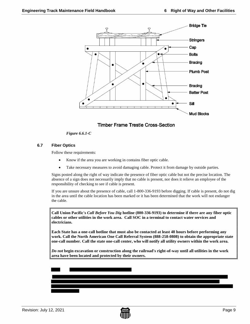
Engineering Track Maintenance Field Handbook 6 Right of Way and Other Facilities
Revision: July 12, 2021 Page 9
6.0 RIG
HT
-OF
-WA
Y
& F
AC
ILIT
IES
Figure 6.6.1-C
6.7 Fiber Optics
Follow these requirements:
Know if the area you are working in contains fiber optic cable.
Take necessary measures to avoid damaging cable. Protect it from damage by outside parties.
Signs posted along the right of way indicate the presence of fiber optic cable but not the precise location. The
absence of a sign does not necessarily imply that no cable is present, nor does it relieve an employee of the
responsibility of checking to see if cable is present.
If you are unsure about the presence of cable, call 1-800-336-9193 before digging. If cable is present, do not dig
in the area until the cable location has been marked or it has been determined that the work will not endanger
the cable.
Call Union Pacific's Call Before You Dig hotline (800-336-9193) to determine if there are any fiber optic
cables or other utilities in the work area. Call SOC in a terminal to contact water services and
electricians.
Each State has a one-call hotline that must also be contacted at least 48 hours before performing any
work. Call the North American One Call Referral System (888-258-0808) to obtain the appropriate state
one-call number. Call the state one-call center, who will notify all utility owners within the work area.
Do not begin excavation or construction along the railroad's right-of-way until all utilities in the work
area have been located and protected by their owners.
6 Right of Way and Other Facilities Engineering Track Maintenance Field Handbook
Page 10 Revision: July 12, 2021

Engineering Track Maintenance Field Handbook 6 Right of Way and Other Facilities
Revision: July 12, 2021 Page 11
6.0 RIG
HT
-OF
-WA
Y
& F
AC
ILIT
IES
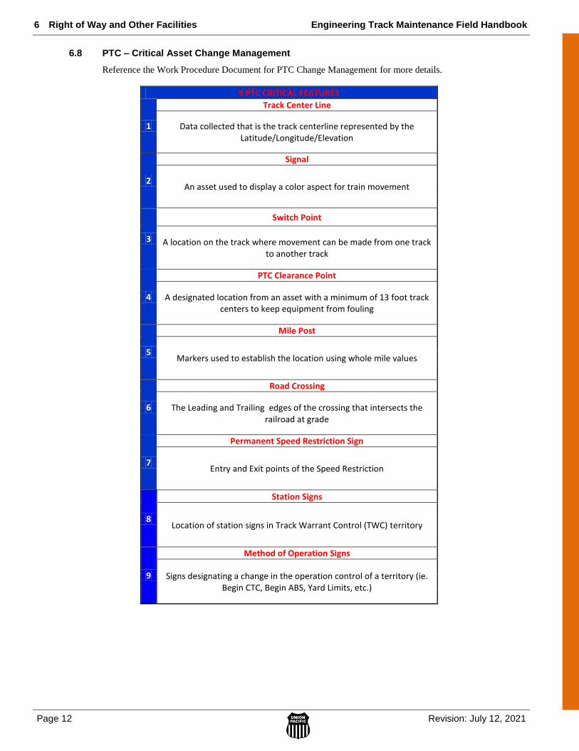
6 Right of Way and Other Facilities Engineering Track Maintenance Field Handbook
Page 12 Revision: July 12, 2021
6.8 PTC – Critical Asset Change Management
Reference the Work Procedure Document for PTC Change Management for more details.
9 PTC CRITICAL FEATURES
1
Track Center Line
Data collected that is the track centerline represented by the Latitude/Longitude/Elevation
2
Signal
An asset used to display a color aspect for train movement
3
Switch Point
A location on the track where movement can be made from one track to another track
4
PTC Clearance Point
A designated location from an asset with a minimum of 13 foot track centers to keep equipment from fouling
5
Mile Post
Markers used to establish the location using whole mile values
6
Road Crossing
The Leading and Trailing edges of the crossing that intersects the railroad at grade
7
Permanent Speed Restriction Sign
Entry and Exit points of the Speed Restriction
8
Station Signs
Location of station signs in Track Warrant Control (TWC) territory
9
Method of Operation Signs
Signs designating a change in the operation control of a territory (ie. Begin CTC, Begin ABS, Yard Limits, etc.)
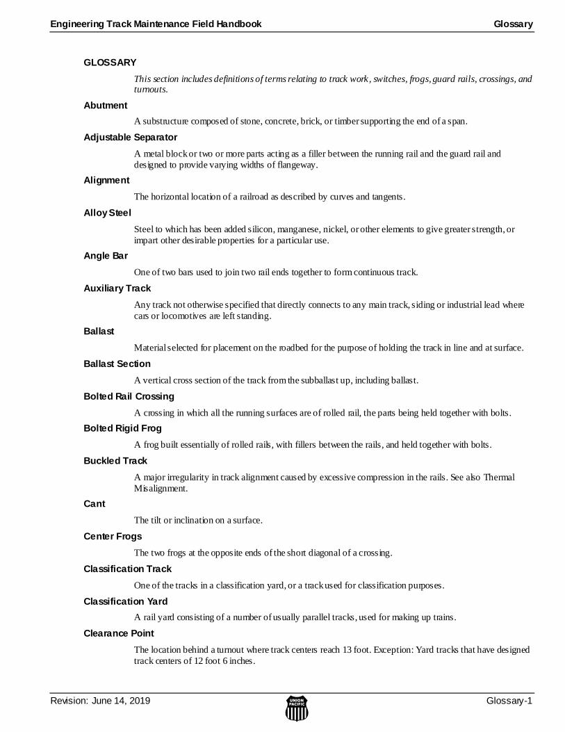
Engineering Track Maintenance Field Handbook Glossary
Revision: June 14, 2019 Glossary-1
GLOSSARY
This section includes definitions of terms relating to track work, switches, frogs, guard rails, crossings, and turnouts.
Abutment
A substructure composed of stone, concrete, brick, or timber supporting the end of a span.
Adjustable Separator
A metal block or two or more parts acting as a filler between the running rail and the guard rail and
designed to provide varying widths of flangeway.
Alignment
The horizontal location of a railroad as described by curves and tangents.
Alloy Steel
Steel to which has been added silicon, manganese, nickel, or other elements to give greater strength, or
impart other desirable properties for a particular use.
Angle Bar
One of two bars used to join two rail ends together to form continuous track.
Auxiliary Track
Any track not otherwise specified that directly connects to any main track, siding or industrial lead where
cars or locomotives are left standing.
Ballast
Material selected for placement on the roadbed for the purpose of holding the track in line and at surface.
Ballast Section
A vertical cross section of the track from the subballast up, including ballast.
Bolted Rail Crossing
A crossing in which all the running surfaces are of rolled rail, the parts being held together with bolts.
Bolted Rigid Frog
A frog built essentially of rolled rails, with fillers between the rails, and held together with bolts.
Buckled Track
A major irregularity in track alignment caused by excessive compression in the rails. See also Thermal
Misalignment.
Cant
The tilt or inclination on a surface.
Center Frogs
The two frogs at the opposite ends of the short diagonal of a crossing.
Classification Track
One of the tracks in a classification yard, or a track used for classification purposes.
Classification Yard
A rail yard consisting of a number of usually parallel tracks, used for making up trains.
Clearance Point
The location behind a turnout where track centers reach 13 foot. Exception: Yard tracks that have designed
track centers of 12 foot 6 inches.

Glossary Engineering Track Maintenance Field Handbook
Glossary-2 Revision: June 14, 2019
Closure Rails
The rails located between the parts of any special trackwork layout, as the rails between the switch and the
frog in a turnout (sometimes called the lead rails or connecting rails); also the rails connecting the frogs of a
crossing or adjacent crossings.
Company Material
Material transported by a particular railroad such as rail, cross ties, ballast, fuel oil, etc., used in connection
with its operations.
Compound Curve
A continuous curve composed of two or more different curves put together with no tangent in between
them, curving in the same direction.
Compromise Joint (Trackwork)
A rail joint between rails of different height and section, or rails of the same section but of different joint
drillings.
Compromise Rail
A relatively short section of rail where one end is forged to a different section of rail.
Conformal Frog
A frog with a 1:20 sloped running surface designed to better fit the profile of wheels.
Connecting Rod
The rod that connects the switch stand and switch rod.
Connecting Track
A track defined as such in EFMS and the Track Inspection System, usually a track or a wye that connects
two subdivisions or railroads.
Continuous Welded Rail (CWR)
Rail length that is 400 feet or longer.
Controlled Siding
A siding within CTC or Interlocking limits where a signal indication authorizes the siding’s use.
Creosote
A tar distillate produced by high-temperature carbonization of bituminous coal and used in wood treatment.
Crib
The lateral space between two railroad ties.
Cross Level
The distance one rail is above or below another. This should not be confused with superelevation on curves.
Cross Tie
The transverse member of the track structure to which the rails are spiked or otherwise fastened to provide
proper gauge and to cushion, distribute, and transmit the stresses of traffic through the ballast to the
roadbed.
Crossing (Rail)
A structure, used where one track crosses another at grade, consisting of four connected frogs.
Crossing Plates
Plates interposed between a crossing and the ties or other timber to protect the ties and to better support the crossing by distributing the loads over larger areas.
Engineering Track Maintenance Field Handbook Glossary
Revision: June 14, 2019 Glossary-3
Crossover
A combination of two switches that connect two adjacent tracks.
Crossover, Double
Two crossovers that intersect between the connected tracks.
Crossover, Universal
Two crossovers in opposite directions.
Curve, Compound
A continuous change in direction of alignment by means of two or more contiguous simple curves of different degrees having a common tangent at their junction points.
Curve, Degree of
The angle subtended at the center of a simple curve by 100 ft. chord.
Curve, Reverse
Two contiguous simple curves in opposite directions, with a common tangent at their junction point.
Curve, Simple
A continuous change in direction of alignment by means of an arc of a single radius.
Curve, Vertical
A transition in the track to connect two intersecting grade lines.
Curved Closure Rail
The rail between the switch point and frog on the diverging side of a turnout.
Curved Lead
The distance between the actual point of the switch and the half-inch point of the frog, measured on the
outside gauge line of the turnout.
Departure Track
One of the tracks in a departure yard on which outgoing cars are placed.
Departure Yard
A rail yard where trains are assembled and made ready for departure.
Derail
A safety device, attached to one rail of a siding or storage track that will cause a car to be derailed in the
event it rolls free towards a main track where it could cause a major accident.
Derailment
Anytime the wheels of a car or engine come off the head of the rail.
Drift Pin
A special railroad tool of round steel tapered for insertion to align holes by striking the large end.
Drill Track
A track connecting with the ladder track, over which locomotives and cars move back and forth in
switching.
Dutchman
Short piece of rail that can be used to reduce the gap between rails ends. Used to make emergency or
temporary movement of trains over a wide joint gap. Must be used within the limits of joint bars.
Glossary Engineering Track Maintenance Field Handbook
Glossary-4 Revision: June 14, 2019
Easer Rail (or Easer)
A rail placed with its head along the outside and close up to the head of the running rail and sloped at the
ends to provide a bearing for the overhanging portion of hollowed-out treads of worn wheels.
Elevation (of Curves) Superelevation
The vertical distance that the outer rail is above the inner rail.
End Frogs
The two frogs at the opposite ends of the long diagonal of a crossing.
Expansion Shim
Spacer inserted between ends of abutting rails while track is being laid to provide allowance for expansion
of steel when temperature changes.
Facing Point Switch
A track switch, the points of which face traffic approaching in the direction for which the track is signaled.
Fastenings
Joint bars, bolts, clips, lag screws and spikes.
Fastenings, Auxiliary
Locknuts, spring washers, tie plates, rail braces, cotter pins and anti-creeping devices.
Federal Railroad Administration (FRA)
An agency of the U.S. Department of Transportation with jurisdiction over matters of railroad safety.
Fiber Optics
Light transmission through very fine flexible glass rods .
Field Side
The side of a rail opposite the gauge side.
Field Weld
A weld joining two rails together after rails are installed in track.
Filler Block (Trackwork)
A steel block molded and designed to keep uniform the angle spread between lead and turnout rails and
frogs, etc.
Flange Lubricator
A device by which either grease or oil can be applied to the flanges of a locomotive driving wheel for the
purpose of preventing flange wear and cutting. Rail lubricators, mounted along the rail in high curvature
territory are also used to apply lubricant to passing flanges to reduce both wheel and rail wear.
Flangeway
The open way through a track structure that provides a passageway for wheel flanges.
Flangeway Depth
The depth of the wheel flange passageway.
Flangeway Width
The distance between the gauge line and the guard line of a track structure, which provides a passageway
for wheel flanges.
Flare
A tapered widening of the flangeway at the end of the guard line of a track structure, as at the end of a guard rail or at the end of a frog or a crossing wing rail.

Engineering Track Maintenance Field Handbook Glossary
Revision: June 14, 2019 Glossary-5
Flare Opening
The distance between the gauge line and the guard line of a track structure at the wider end of the flare.
Flat Yard
A yard where car switching is dependent on locomotive power with little assistance from gravity.
Foot Guard
A filler for the space between converging rails to prevent human feet from becoming accidentally wedged
between the rails.
Fouling Point
The location behind turnouts that measures 50 feet beyond the clearance point.
Frog
A track structure used at the intersection of two running rails to provide support for wheels and
passageways for their flanges, thus permitting wheels on either rail to cross the other.
Frog Angle
The angle formed by the intersecting gauge lines of a frog.
Frog Heel
The end of a frog furthest from the switch, or opposite the point end.
Frog Number
The ratio of the spread to the length of the frog.
Frog Plates
Any specially designed plate used between the toe and heel of a frog.
Frog Point
The part of a frog lying between the gauge lines extending from their intersection toward the heel end.
(a) Theoretical Point
The point of intersection of the gauge lines of a frog.
(b) Half-Inch Point
A point located at a distance from the theoretical point towards the heel equal in inches to one-half
the frog number, and at which the spread between the gauge lines is one-half inch. It is the origin
from which measurements are made.
(c) Actual Point
The physical location of the point of frog. This is called the 5/8” point.
Frog, Throat
The point at which the converging wings of a frog are closest together.
Frog, Toe
The end of a frog nearest the switch.
Fusee
A warning device consisting of a cardboard tube filled with a combustible mixture of chemicals that burns
brightly when ignited and remains burning for varying lengths of time. Fusees are ignited and dropped on the right-of-way to indicate to a following train the presence of stopped or slow-moving equipment ahead.
Gauge (Track)
See Standard Gauge.
Glossary Engineering Track Maintenance Field Handbook
Glossary-6 Revision: June 14, 2019
Gauge Line
A line 5/8 in. below the top of the center line of head of running rail along the side nearer the center of the
track.
Gauge Plate
A metal plate, extending from rail to rail, used to maintain gauge of track.
Gauge Rod
A device for holding track to correct gauge, generally consisting of 1-1/4-in. rod with a forged jaw on one
end and a malleable jaw on the other end, adjustable through a lock nut.
Gauntlet Track
A section of railroad track (as over a bridge or in a narrow pass) where two lines of track overlap so that
one rail of each track is within the rails of the other. In such cases no switch is needed. The crossing of the
two inner rails is made by ordinary frogs.
Geotextile
A material designed to permit the passage of water through it, but not particles of soil or dirt carried by the
water. Used under ballast to function as a subballast. Also used to wrap corrugated or loose jointed pipe and to line drainage trenches or French drains. Also called “filter fabric” or “engineering fabric.”
Grade (Degree Of)
As used in connection with railway line, the rise or fall in a track expressed as a ratio to 100 feet of
horizontal track.
Grade Crossing
An intersection of a highway with a railroad at the same level.
Guard Check Gauge
The distance between guard line and gauge line, measured across the track at right angles to the gauge
lines.
Guard Face Gauge
The distance between guard lines, measured across the track at right angles to the gauge lines.
Guard Line
A line along the side of the flangeway that is nearer the center of the track and at the same elevation as the
gauge line.
Guard Rail
A rail or other structure laid parallel with the running rails of a track to prevent wheels from being derailed;
or to hold wheels in correct alignment to prevent their flanges from striking the points of turnout or crossing frogs or the points of switches. A rail or other structure laid parallel with the running rails of a
track to keep derailed wheels adjacent to running rails.
Guard Rail (Frog)
A rail or other device to guide the wheel flange so that it is kept clear of the point of the frog.
Guard Rail (Switch)
A rail or other track structure laid parallel with the running rail ahead of a split switch and forming a
flangeway with the running rail, to hold the wheels of rolling stock in correct alignment when approaching the switch.
Guard Rail Brace
A metal shape designed to fit the contour of the side of the guard rail and extend over the tie, with
provision for fastening thereto, to restrain the moving or tilting of the guard rail away from the running rail.
Engineering Track Maintenance Field Handbook Glossary
Revision: June 14, 2019 Glossary-7
Guard Rail Brace, Adjustable
A guard rail brace, which may be adjustable laterally with respect to the rail, to vary the distance between
the guard rail and the running rail.
Guard Rail Clamp
A device consisting of a yoke and fastenings designed to engauge the running rail and the guard rail and
hold them in correct relation to each other.
Guard Rail, One-Piece
A guard rail consisting of a single complete unit, either fabricated or cast, designed so that no auxiliary parts or fastenings other than spikes are required for its installation.
Head Rod
A rod connecting the points of a switch or movable point frog, by means of which the relative location of
the points is maintained and to which the operating rod is attached.
Head Separation
The point on a switch rail where the head of the rail attains its full width.
Head Block Ties
The ties to which a switch stand is attached.
Heel (of Frog)
The end of the frog farthest from the switch.
Heel Block
A steel block, through which bolt holes are drilled, that is placed between the heel of a switch point and its
stock rail.
Heel Length
The distance between the heel end and the half-inch point of a frog, measured along the gauge line.
Heel Spread
The distance, at the heel, between the gauge line of a switch rail and the gauge line of its stock rail. (This
has been standardized at 6-1/4 in. for AREMA style switches.)
House Track
A track diverging from the main track or siding used to set out cars or store equipment.
Hump
The hill over which cars are pushed for classification in a hump yard.
Industrial Track
A switching track serving industries, such as mines, mills, smelters, and factories.
Insulated Rail Joint
A joint in which electrical insulation is provided between adjoining rails.
Insulated Switch
A switch in which the fixtures, principally the gauge plates and the switch rods, connecting or reaching
from one rail to the opposite rail, are provided with insulation so that the electric track circuit will not be shunted.
Insulation
A device or material that prevents the flow of electric current in a track circuit from passing from one rail to the other or through switches and other track structures.

Glossary Engineering Track Maintenance Field Handbook
Glossary-8 Revision: June 14, 2019
Joint Bar
A steel bar commonly used in pairs for joining rail ends in railroad track.
Joint Gap
The distance between the ends of rails joined by joint bars.
Joint Rail Drilling
The spacing of holes in the ends of rails or other track structures to receive the bolts for fastening joint bars.
Joint, Permanent
A rail joint that will remain in track.
Joint, Rail
The area of fastenings and rail where rail ends meet.
Joint, Supported
A rail joint that sits directly on top of a tie.
Joint, Suspended
A rail joint that sits between two consecutive ties.
Knuckle Rail
A bent rail, or equivalent structure, forming the obtuse point against which the movable center points, of a movable point crossing or slip switch, rest when set for traffic.
Lead (Actual)
The length between the actual point of the switch and the half-inch point of the frog measured on the line of
the main track.
Lead (Theoretical)
The distance from the theoretical point of switch to the theoretical point of the frog, measured on the line of
the main track.
Lead Track
An extended track connecting to a series of yard tracks.
Line
The condition of the track with regard to uniformity in direction over short distances on tangents, or
uniformity of curvature over short distances on curves.
Lock Nut
A special type of nut with a feature that prevents the nut from turning off the bolt once it is secured. Lock
nuts are not reusable since removing them generally destroys the locking feature.
Lock Rod
A rod, attached to the front rod or lug of a switch, movable point frog, or derail, through which a locking
plunger may extend when the switch points or derail are in the normal or reverse position.
Lock Washer
A washer designed to prevent undesired loosening of a nut after it has been tightened.
Main Track (Line)
A track extending through yards and between stations that must not be occupied without authority or
protection. (General Code)
Manganese Steel
Steel containing a high percent of manganese; an alloy of steel to increase hardness and wear resistance.
Engineering Track Maintenance Field Handbook Glossary
Revision: June 14, 2019 Glossary-9
Manganese Steel Insert Crossing
A crossing in which a manganese steel casting is inserted at each of the four intersections, being fitted into
rolled rails and forming the points and wings of the crossing frogs.
Manganese Tipped Switch
A split switch in which the head of one or both of the switch rails is cut away in the point portion and
manganese steel insert is fastened to the rail to form the point.
Monday Maul
Sledge hammer.
Movable Center Point
One of the movable tapered rails of a movable point crossing or slip switch.
Movable Point Frog
A frog equipped with points that are movable in the same manner as the points on a switch.
Movable Point Crossing
A crossing of small angle in which each of the two center frogs consists essentially of a knuckle rail and
two opposed movable center points with the necessary fixtures.
Passing Track
A track to the main track for meeting or passing trains. Today this is called a siding.
Planing, Bottom
The cut planed at an angle on the bottom of the base of the switch rail from the point and towards the heel
to allow the switch rail to rest on the top of the base of the stock rail when the switch rail is closed.
Planing, Chamfer Cut
The vertical beveling of the gauge side of the switch point to produce a sharp edge that prevents wheel
flanges from striking the point.
Planing, Side
The cuts made on the sides of the head of the switch rail to form the taper.
Planing, Top
The cut made on the top of the head of the switch rail from the point and to approximately the head
separation.
Point of Switch (Actual)
The end of the switch rail farther from the frog; the point where the spread between the gauge lines of the
stock rail and the switch rail is sufficient for a switch point.
Point of Switch (Theoretical) of Vertex
The point where the gauge line of the switch rail, if extended, would intersect the gauge line of the stock
rail.
Point Rail, Switch Rail, or Switch Point
The tapered rail of a split switch.
Pull-Apart
A condition that exists at a rail joint when all the bolts in one rail end are missing and the two rail ends
have gapped.
Rail
In track, a rolled steel shape, commonly a T-section, designed to be laid end to end in two parallel lines on
cross ties or other suitable supports to form a track for railway rolling stock.
Glossary Engineering Track Maintenance Field Handbook
Glossary-10 Revision: June 14, 2019
Rail Anchor
A device attached to the base of a rail bearing against a cross tie to prevent the rail from moving
longitudinally under traffic.
Rail Bond
A short metal cable attached to adjacent rails at the joints to ensure proper electrical continuity across the
joint.
Rail Brace
A bracing device used at switches, movable point frogs, etc., in combination with switch, tie, or gauge plates for holding the rail from lateral roll.
Rail Brace (Switch)
A metal shape designed to fit the contour of the side of the stock rail and extend over the switch plate, with
provision for fastening through the plate to the tie, to restrain the lateral roll of the stock rail.
Rail Brace, Adjustable (Switch)
A rail brace that may be adjusted laterally with respect to the stock rail, to compensate for variations in the
dimensions of the rail and to permit adjusting for wear.
Rail Creep
Longitudinal sliding of rails in track under traffic or because of temperature changes.
Rail Joint
A fastening designed to unite the abutting ends of contiguous rails.
Rail Lubricator (Flange)
A device designed to apply grease to the gauge side of the rail head at the beginning of a curve, to
minimize wear of the rail and wheel flange or to eliminate noise.
Rail Lubricator (Top of Rail)
A device designed to apply lubrication to the top of the rail head to minimize wear of the rail and reduce lateral forces, or to eliminate noise.
Railbound Manganese Steel Frog
A frog consisting essentially of a manganese steel body casting fitted into and between rolled rails and held
together with bolts.
Reinforcing Rail
A bent rail placed with its head along the outside or close up to the head of a knuckle rail to strengthen it
and to act as an easer rail; or a piece of rail similarly applied to a movable center point.
Relay Rails
Rails taken up from tracks where formerly used, suitable for relaying in other tracks.
Retarder
A braking device, usually power operated, built into a railway track to reduce the speed of cars by means of
brake-shoes which, when set in braking position, press against the sides of the lower portions of the wheels.
Reverse Elevation
In curved track, when the outer rail is lower than the inner rail.
Right of Way
The strip of land on which a railroad track is built.
Rip Track
A car repair facility with one or more tracks.
Engineering Track Maintenance Field Handbook Glossary
Revision: June 14, 2019 Glossary-11
Roadbed
The foundation upon which the ballast, ties and rails of a railroad are laid.
Running Rail
a.) The rail or surface on which the tread of the wheel bears.
b.) Longitudinal movement of rail caused by an insufficient fastening system.
Running Track
A track reserved for movement through a yard.
Scale Track
A track leading to and from, and passing over a track scale.
Screw Spike
A cylindrical threaded spike, designed to be turned with a special wrench into holes bored in ties, to secure
rails or to act as a tie plate holder.
Section Limits
A division of railroad into specific territories for maintenance purposes. Sections are usually inspected and
maintained by an assigned group of men.
Self-Guarded Frog (Flange Frog)
A frog provided with guides or flanges, above its running surface, which contact the tread rims of wheels
for the purpose of safely guiding their flanges through the frog.
Shaved Anchor
A rail anchor with a lip that remains lower than the top of the base of the rail when it is locked in so that the switch point will not contact it when thrown.
Side Track
An auxiliary track to the main track.
Siding
A track connected to the main track and used for meeting or passing trains. Locations of sidings are shown
in the timetable. (General Code)
Slide Fence
A fence interconnected to the signal system placed at the bottom of a cut to warn trains of rock slides by the use of signal indication.
Slip Switch, Double
A combination of a rail crossing and two turnouts interconnected into one assembly.
Slip Switch, Single
A combination of a rail crossing and one turnout interconnected into one assembly.
Snow Fence
A barrier placed along the right of way to prevent blowing snow from drifting onto the track.
Solid Manganese Steel Frog
A frog consisting entirely of a single manganese steel casting.
Special Trackwork
Any trackwork consisting of more than two rails and ties. Examples are turnouts, switches and crossing
frogs.
Specification
A set of instructions that provide the requirements of a material to be manufactured or constructed.
Glossary Engineering Track Maintenance Field Handbook
Glossary-12 Revision: June 14, 2019
Spike
A long steel square nail with a cutting edge used to fasten track components in place.
Spiked Switch
A switch whose points are held in fixed position by a spike to prevent the switch from being thrown or to
prevent trains from using track that has been taken out of service.
Spiral
The gradual and uniform increase and decrease of curvature between the tangent and the full curve.
Split Switch
A track structure consisting of two movable point rails and necessary fixtures used to divert rolling stock
from one track to another.
Split Switch with Graduated Risers
A split switch in which the switch points are gradually elevated by means of graduated riser plates until
they reach the required height above the stock rail.
Split Switch with Uniform Risers
A split switch in which the switch points have a uniform elevation on riser plates for the entire length of the
switch, the point rail rise being run off back of the switch points in the closure rails.
Spring Rail Frog
A frog with a movable wing rail that is held against the point rail by springs, thus making an unbroken
running surface for wheels using one track, whereas the flanges of wheels on the other track force the
movable wing rail away from the point rail to provide a passageway.
Spring Rail Frog, Right-Hand and Left-Hand
Standing at the toe end of a spring rail frog and looking toward its point, a right-hand frog has the movable
wing rail located on the right-hand side, and a left-hand frog has the movable wing rail located on the left-hand side.
Spring Switch
A switch with a spring mechanism that returns the switch points to the original position after they are
trailed through.
Spring Washer
A component designed to apply compressive force to prevent reverse movement of a nut.
Spur
A single-ended track diverging from a main or other track.
Standard Gauge
The standard distance between rails of North American railroads: 4 ft. 8-1/2 in. measured between the
inside faces of the rail heads 5/8 in. below the top of the rail.
Stock Rail
The rail against which the point of a switch or derail fits.
Stock Rail Bend
The bend placed in the stock rail at or near the switch point to match the switch rail angle.
Storage Track
A track on which cars are placed when awaiting disposition or when not in service.
Straight Closure Rail
The rail between the switch point and frog on the straight side of a turnout.
Engineering Track Maintenance Field Handbook Glossary
Revision: June 14, 2019 Glossary-13
String Lining
a.) A method to determine the alignment of a curve by measuring offset from a string line to the gauge
side of the high rail.
b.) When a train pulls it’s consist off the low side of a curve.
Stripped Joint
See Pull-Apart.
Subballast
Any material spread on the finished subgrade of the roadbed below the ballast to provide better drainage,
prevent upheaval by frost, and better distribute the load over the roadbed.
Subgrade
The finished surface of the roadbed below the ballast and track.
Sun Kink
See Thermal Misalignment.
Switch
A track structure with movable rails to divert rolling stock from one track to another.
Switch Angle
The angle included between the gauge lines of the switch rail at its point and the stock rail.
Switch Circuit Controller
A device connected at the point to switch, derail, or moveable point frog which will electrically indicate an
open switch condition when the switch point is open 1/4" or more.
Switch Heater
A device that will heat the area around a switch to melt snow and ice.
Switch Heel
The designated location on the switch point where the heel block is located.
Switch Machine
A machine used to throw track switches. Switch machines can be powered operated or used manually.
Switch Plate
Any specially designed tie plate for use in the switch area of a turnout.
Switch Point
A machined rail with a sharp end mated against a stock rail used to divert rolling stock from one track to
another.
Switch Point Derail
A device consisting of at least one switch point for the intended purpose of derailing rolling stock.
Switch Point Protector
A device that diverts a rolling wheel away from the switch point.
Switch Rail Brace
A brace placed against a running rail to dissipate lateral force thus preventing rail turnover.
Switch Rod
A rod connecting the two points of a switch which maintains the proper distance between the points.
Switch Stand
A device for the manual operation of a switch.
Glossary Engineering Track Maintenance Field Handbook
Glossary-14 Revision: June 14, 2019
Switch Tie
Ties made of various lengths used in a switch, turnout or special trackwork.
Tangent
A section of track that connects two curves.
Thermal Misalignment
An irregularity in track alignment caused by excessive compressive forces in the rail.
Thermite Weld
A weld, made by pouring molten materials into the gap between rail ends, that fuses the rail ends together.
Throat of Frog
The location ahead of the point at which the wing rails of a frog are closest together.
Throw of Switch
The distance between the back of the open switch point and gauge line of the stock rail measured along the
center line of the No. 1 switch rod. (This distance is standardized at 4-3/4 in.)
Tie Pad
A dampening device located between the rail and the tie.
Tie Plate
A steel plate between a rail and a tie.
Tie Plug
A wood or composite material used to fill holes in ties from which spikes have been removed.
Toe (of Frog)
End of a frog nearest the switch.
Toe Length
The distance between the toe end of the frog and the half-inch point of the frog, measured along the gauge
line.
Track
An assembly of rails, ties, ballast and fastenings over which cars, locomotives, and trains are moved.
Track Bolt
A bolt with a button head and oval, or elliptical neck, and a threaded nut designed to fasten rails and joint
bars.
Track Crossing (slang; Diamond)
A track component consisting of four connected frogs that permits one track to cross another at grade.
Track Shims
Flat wood boards of length and width similar to tie plates. They are placed between the ties and the tie
plates when the ballast is frozen to correct surface irregularities.
Transition Rail (Trackwork)
A manufactured rail using the same rail section that is machined to compensate for various amounts of rail
head loss.
Tread
a.) The top surface of the rail that contacts the wheel.
b.) The portion of the wheel that contacts the top of the rail.

Engineering Track Maintenance Field Handbook Glossary
Revision: June 14, 2019 Glossary-15
Turnback Curve
The curve(s) directly behind the diverging side of a turnout.
Turnout
A section of trackwork that allows rolling stock to be diverted from one track to another.
Turnout, Panel
A pre-assembled turnout complete or in sections.
Turnout Plates
Any specially designed tie plate used between the heel of the switch point and toe of the frog.
Turnout Number (Size)
The number corresponding to the size of the frog used in the turnout.
Washout
An erosion of the permanent roadbed by storm or flood.
Wheel Flange
The portion of the wheel that protrudes down from the wheel tread to guide rolling stock along the track.
Wide Gauge
Any gauge wider than standard gauge caused by track deterioration or improper installation.
Wye
A track arrangement shaped like the letter Y but with a connecting segment between the two upper legs to
enable the turning of equipment.
Yard
A system of tracks, other than main tracks and sidings, used for making up trains, storing cars, and other
purposes.