engineering the surface of licoo electrodes using … the surface of licoo 2 electrodes using atomic...
TRANSCRIPT

Engineering the surface of LiCoO2 electrodes using atomic layer deposition for stable high-voltage lithium ion batteries
Jin Xie1, Jie Zhao1, Yayuan Liu1, Haotian Wang2, Chong Liu1, Tong Wu1, Po-Chun Hsu1, Dingchang Lin1,
Yang Jin1, and Yi Cui1,3 ()
1 Department of Materials Science and Engineering, Stanford University, Stanford, CA 94305, USA 2 Department of Applied Physics, Stanford University, Stanford, CA 94305, USA 3 Stanford Institute for Materials and Energy Sciences, SLAC National Accelerator Laboratory, Menlo Park, CA 94025, USA
Received: 25 January 2017
Revised: 7 March 2017
Accepted: 12 March 2017
© Tsinghua University Press
and Springer-Verlag Berlin
Heidelberg 2017
KEYWORDS
Lithium ion batteries,
lithium cobalt oxide,
atomic layer deposition
ABSTRACT
Developing advanced technologies to stabilize positive electrodes of lithium
ion batteries under high-voltage operation is becoming increasingly important,
owing to the potential to achieve substantially enhanced energy density for
applications such as portable electronics and electrical vehicles. Here, we deposited
chemically inert and ionically conductive LiAlO2 interfacial layers on LiCoO2
electrodes using the atomic layer deposition technique. During prolonged cycling
at high-voltage, the LiAlO2 coating not only prevented interfacial reactions
between the LiCoO2 electrode and electrolyte, as confirmed by electrochemical
impedance spectroscopy and Raman characterizations, but also allowed lithium
ions to freely diffuse into LiCoO2 without sacrificing the power density. As a
result, a capacity value close to 200 mA·h·g–1 was achieved for the LiCoO2 electrodes
with commercial level loading densities, cycled at the cut-off potential of 4.6 V
vs. Li+/Li for 50 stable cycles; this represents a 40% capacity gain, compared
with the values obtained for commercial samples cycled at the cut-off potential
of 4.2 V vs. Li+/Li.
1 Introduction
Ever since the commercialization of lithium ion
batteries, LiCoO2 has been widely used as a positive
electrode material [1, 2]. The combination of its relatively
high discharge plateau and high tapped density makes
LiCoO2 an ideal material to provide high specific
energy density and volumetric energy density, both
of which are important criteria for energy storage
solutions. Even today, the majority of mobile electronics
are powered by LiCoO2-based lithium ion batteries.
However, emerging applications such as the elec-
trification of the transportation system, where the
stability, safety, and efficiency of batteries are of great
Nano Research
DOI 10.1007/s12274-017-1588-1
Address correspondence to [email protected]

| www.editorialmanager.com/nare/default.asp
2 Nano Res.
concern, demand superior capabilities as well as provide
great opportunities for lithium ion batteries [3–6].
The potential application of LiCoO2-based cathodes
in electrical vehicles has been hindered by the poor
stability of LiCoO2 when cycled with a high cut-off
potential or at elevated temperatures. In spite of a
high theoretical capacity of 272 mA·h·g–1, only ~0.5
Li+ per LiCoO2 (~137 mA·h·g–1) is utilized in the
lithiation/delithiation process to prevent severe side
reactions, which typically occur at an accelerated rate
when LiCoO2 cathodes are cycled beyond 4.2 V vs.
Li+/Li [2, 5, 6]. The side reactions could lead to fast
capacity decay and, more importantly, safety hazards.
To solve the above-mentioned dilemma between
high capacity and long stability, a variety of surface
modification methods have been proposed to protect
LiCoO2 from degradation [7–11]. The majority of the
surface coating processes are based on solution phase
methods to coat metal oxides—such as ZrO2, Al2O3,
and SiO2—on individual LiCoO2 particles [7–9, 12, 13].
Although the direct coating process on particles has
been shown to be easy-to-handle and cost-effective,
the coating layers may break and expose fresh LiCoO2
surfaces during harsh slurry mixing and electrode
calendaring processes. In addition, the power density
is sacrificed as the low ionic and electronic conduc-
tivities of the coating materials may create barriers in
between LiCoO2 particles. Therefore, a more effective
strategy to coat metal oxides on the entire LiCoO2
electrode has been demonstrated by several groups by
using atomic layer deposition (ALD) [10, 11, 14, 15].
While the electrode stability improved after coating,
the power density was inevitably compromised, as
most metal oxides prepared by ALD are poor lithium
ion conductors. To solve this problem, an effective
coating with both excellent chemical stability and ionic
conductivity is needed.
Here, we explore ALD of LiAlO2 thin films directly
on LiCoO2 electrodes with a commercial level of
loading to improve their stability without sacrificing
power density or energy density. While effective LiAlO2
coating on LiCoO2 particles by using solution phase
synthesis has been reported by Cao et al. [16], the
strategy of direct and uniform ALD coating at the
electrode scale provides two important advantages.
First, electrical conductivity in between individual
particles is not compromised, as the coating is
conducted directly on the electrode level. The nature
of the ALD technique ensures that the coating
occurs on the surface, generating a uniform thin
film covering the entire electrode while maintaining
the interconnectivity of the LiCoO2 particles. The
sequence of slurry coating and calendaring, followed
by the final ALD coating, also minimizes the possibility
of film cracking during processing. Second, as ALD
processes are flexible and integrable, different ALD
chemistries can be combined to design more complex
thin films [17–20]. Another dilemma of using ALD to
coat battery electrodes arises from the compromise
between electrochemical stability and rate capability.
Typical ALDs follow an island nucleation model, with
subsequent linear growth; often times, the resulting
metal-oxide films are poor lithium ion conductors.
Therefore, on the one hand, thick and uniform coating,
which would effectively protect LiCoO2 from degrading,
limits the power performance of coated electrodes.
Conversely, thin coatings enable LiCoO2 to show
good power densities even after thin-film coating,
but have limited stability enhancement as the coating
is non-uniform (island nucleation), allowing not only
lithium ions to pass through, but also side reactions
to occur. In this work, by doping Li2O into Al2O3, the
resulting LiAlO2 coating layer allowed Li ions to pass
through and, at the same time, prevented side reactions
between the electrolyte and LiCoO2 surface. Owing
to the presence of a LiAlO2 thin-film interfacial layer
on the surface of the LiCoO2 electrode, the increase
in cell impedance upon cycling could be significantly
suppressed, and the formation of the Co3O4 phase
on the surface of the LiCoO2 electrodes during
overcharging was prevented. As a result, improved
cycling stability with a wide electrochemical window
and at an elevated temperature was achieved.
2 Results and discussion
While thin-film coating may improve the stability of
electrode materials [7–11], it also raises two critical
challenges: retaining power density and energy density
after coating. As shown in Fig. 1(a), we propose coating
the LiCoO2 electrode with LiAlO2 directly by using
ALD to simultaneously preserve the electron transport

www.theNanoResearch.com∣www.Springer.com/journal/12274 | Nano Research
3 Nano Res.
pathways and lithium ion transport pathways. First,
LiAlO2 thin films were directly deposited on LiCoO2
electrodes instead of LiCoO2 powders. The merit of
this electrode fabrication sequence is to prevent
electrical polarization in between individual LiCoO2
particles. In addition, it minimizes the possibility
of film cracking during slurry mixing and electrode
calendaring processes. Second, LiAlO2 is a solid
electrolyte with lithium ion conductivity depending
on various factors including Li/Al ratio, film orientation,
thickness, and crystallinity [17, 21–23]. Aaltonen et al.
first demonstrated that LiAlO2 films could be obtained
via ALD by alternating Li2O and Al2O3 ALD sub-cycles
during the LiAlO2 ALD process [22], and the lithium
ion conductivity of LiAlO2 improved significantly,
compared with that of pure Al2O3 films [17, 23].
In this study, LiAlO2 thin films were deposited by
alternating Li2O (lithium isopropoxide and water) and
Al2O3 (trimethylaluminum and water) ALD sub-cycles,
using an exposure mode to achieve uniform coverage
on LiCoO2 electrodes with high surface area (Fig. 1(a)).
For characterization purposes, LiAlO2 films were first
deposited on ball-milled LiCoO2 powders for ease of
transmission electron microscopy (TEM) observation.
In Fig. 1(b), 20 cycles of ALD LiAlO2 (10 super-cycles;
one super-cycle consists of one Li2O sub-cycle and one
Al2O3 sub-cycle) were performed. A uniform thin-film
coating with thickness close to 2 nm was obtained.
When the deposition thickness was increased further
after performing 200 ALD cycles, the LiCoO2 core
and LiAlO2 shell structures could be clearly mapped
using energy-dispersive spectroscopy (EDX; Fig. 1(c)).
To check elemental compositions and calculate film
thicknesses quantitatively, inductively coupled plasma
mass spectrometry (ICP-MS) was performed, and the
results are summarized in Figs. 1(d) and 1(e). LiAlO2
films were deposited on silicon wafers, and then
dissolved by HNO3 solution to avoid complications
from Li in LiCoO2. The areal loading density of Li and
Al increased linearly with the number of ALD cycles,
and the Li to Al mole ratio in the film was close to 1.5.
The growth rate of Al2O3 in the Al2O3 sub-cycles of
the LiAlO2 ALD process was found to be close to that
observed for the pure Al2O3 ALD process (Fig. S2 in
the Electronic Supplementary Material (ESM)). In
addition to ICP-MS, X-ray photoelectron spectroscopy
(XPS) was also performed to check the elemental
composition of the as-deposited films on the surface.
Figure 1 (a) Scheme of LiAlO2 coating (purple) on LiCoO2 electrode (dark cyan for LiCoO2 particles and dark grey for conductive carbon) by atomic layer deposition (ALD); (b) transmission electron microscopy characterization of a 20-cycle-ALD LiAlO2 coated LiCoO2 particle; (c) energy-dispersive spectroscopy mapping of a 200-cycle-ALD LiAlO2 coated LiCoO2 particle; (d) Li and Al areal loading density in ALD LiAlO2 films grown on Si wafers, as detected by inductively coupled plasma mass spectrometry (ICP-MS); (e) Li to Al molar ratio in ALD LiAlO2 films grown on Si wafers, as detected by ICP-MS; (f) X-ray photoelectron spectroscopy characterizations of 200-cycle-ALD LiAlO2 film grown on Si wafer.

| www.editorialmanager.com/nare/default.asp
4 Nano Res.
After performing a mild sputtering treatment for 6 s
to remove surface-absorbed carbon impurities, no
carbon residue from ALD precursors was detected
(Fig. 1(f)), indicating high film quality.
The LiAlO2 coating was performed on LiCoO2
electrodes made from industrial LiCoO2 powders.
For all tests, unless specified, commercial LiCoO2
powder purchased from MTI was dried and mixed
with Super C65 and polyimide (PI) with a mass ratio
of 90:5:5 to make cathodes with an average loading of
15 mgLiCoO2·cm–2. Commercial poly(vinylidene fluoride)
(PVDF) binder was replaced with PI, owing to the
low melting point of PVDF, which is below the
ALD operation temperature. The rate performances
of electrodes with and without coating layers were
tested using a typical electrochemical window ranging
from 2.75 to 4.20 V vs. Li+/Li for LiCoO2 (Fig. 2(a)). At
a low rate (10 mA·g–1), the average discharge capacity
of a pristine cathode in the first five cycles approached
142.3 mA·h·g–1. In comparison, cathodes with 20-cycle-
ALD LiAlO2 coating showed almost identical discharge
capacity (140.1 mA·h·g–1) and similar charge/discharge
profiles (Fig. 2(b)). The capacities of LiAlO2 coated
samples were close to those of the pristine LiCoO2
samples at all rates (10, 20, and 50 mA·g–1), except for
a slight difference at the highest rate of 100 mA·g–1
(Fig. 2(c)). Conversely, 20-cycle-ALD Al2O3 (without
lithium doping) coated LiCoO2 exhibited significantly
lower capacity than pristine LiCoO2 at all rates
(10, 20, 50, and 100 mA·g–1). Even at the lowest rate
of 10 mA·g–1, the average discharge capacities of the
20-cycle-ALD Al2O3 coated cathodes in the first five
cycles were lower than 100 mA·h·g–1, presumably
owing to the uniform coverage of the Al2O3 films
deposited by 20 cycles of ALD and the poor lithium
ion conductivity of Al2O3.
The challenge of high energy density can be
overcome by minimizing the loading of inactive
coating materials and extending the electrochemical
window of LiCoO2. LiAlO2 or Al2O3 coating films
obtained by up to 50 cycles of ALD were less than 1%
of the active LiCoO2 weight. The uniformity of the
ALD coating allows using the minimum amount of
inactive materials to coat high surface area electrodes,
which has been a challenge in solution phase synthesis
or solid-state synthesis. More importantly, it is always
Figure 2 Electrochemical measurements. (a) Rate performance of pristine, 20-cycle atomic layer deposition (ALD) LiAlO2 coated and 20-cycle-ALD Al2O3 coated LiCoO2 electrodes tested with an electrochemical window of 2.75–4.20 V vs. Li+/Li; (b) and (c) detailed voltage vs. capacity profiles of pristine, 20-cycle-ALD LiAlO2 coated, and 20-cycle-ALD Al2O3 coated LiCoO2 electrodes tested in Fig. 2(a) at the 3rd cycle (10 mA·g–1) and 18th cycle (100 mA·g–1); (d) rate performance of pristine, 20-cycle-ALD LiAlO2 coated, and 20-cycle-ALD Al2O3 coated LiCoO2 electrodes tested with an electrochemical window of 2.75–4.60 V vs. Li+/Li; (e) comparison of 1st cycle discharge capacities of pristine, LiAlO2 coated, and Al2O3 coated LiCoO2 electrodes with an electrochemical window of 2.75–4.60 V vs. Li+/Li at 50 mA·g–1; (f) electrochemical impedance spectroscopy characterizations of pristine, 20-cycle-ALD LiAlO2
coated, and 20-cycle-ALD Al2O3 coated LiCoO2 electrodes after the 1st cycle.

www.theNanoResearch.com∣www.Springer.com/journal/12274 | Nano Research
5 Nano Res.
of practical interest to extend the electrochemical
windows during cycling, in order to extract more
lithium ions out of LiCoO2 for even greater energy
density. However, the pristine LiCoO2 cathode showed
severe capacity degradation within a few cycles
(Fig. 2(d)) when the electrochemical window was
aggressively expanded to 2.75–4.60 V vs. Li+/Li. In
comparison, both LiAlO2 coated and Al2O3 coated
samples showed decent capacity retention, while
the LiAlO2 coated samples were able to deliver a
significantly higher specific capacity than the Al2O3
coated samples, owing to the ability to conduct lithium
ions in LiAlO2. As the pristine cathodes degraded
rapidly within a few cycles, the statistical results of
the first-cycle specific capacities of cathodes with and
without thin-film coating are here presented to illustrate
the correlation between film thickness/composition
and achievable capacity with a wider electrochemical
window (Fig. 2(e)). In the 1st cycle, at the relatively fast
cycling rate of 50 mA·g–1, the Al2O3 coating of the
LiCoO2 electrodes provided low specific capacities.
After only 20 cycles of ALD Al2O3 coating, the specific
capacity dropped to 79.0 ± 4.1 mA·h·g–1 from 203.3 ±
2.3 mA·h·g–1 of the pristine electrodes. Electrochemical
impedance spectroscopy (EIS) was also conducted
on the samples after the 1st charge cycle, showing a
significantly increased impedance after 20 cycles of
ALD Al2O3 coating. In the case of the ALD LiAlO2
coated electrodes, lithium ions could diffuse into
LiCoO2 through the LiAlO2 thin film, thus exhibiting
a considerably higher initial capacity (i.e., 185.5 ±
5.4 mA·h·g–1 with 20-cycle-ALD LiAlO2 vs. 79.0 ±
4.1 mA·h·g–1 with 20-cycle-ALD Al2O3). When compared
with the pristine LiCoO2 electrode, the LiAlO2 coated
electrodes exhibited indeed a slight decrease in initial
capacity and increase in impedance; thus, further
efforts to develop lithium ion conductive coating films
with higher conductivity by using ALD are needed.
As Al2O3 is not a good lithium ion conductor, the
conduction of lithium ions through a protective Al2O3
film has to go through pinholes. Such defects are
inevitable when considering: (1) The island nucleation
model of atomic-layer-deposited Al2O3, which grows
forming discrete particles instead of a continuous
thin film in the early stage of the ALD process [24];
(2) film cracking in post-growth operations including
electrode handling, coin-cell fabrication, and LiCoO2
particle cracking during cycling [25]. While these
defects allow lithium ions to conduct through at a
discounted rate, compared with what observed in
pristine samples, they also lead to similar electrode
degradation as in pristine samples. For example,
although the LiCoO2 electrode with 10-cycle-ALD Al2O3
coating showed appreciable capacity in the first few
cycles, its capacity decayed at a rate only slightly slower
than that of the pristine LiCoO2 electrode (Fig. 3(a)).
Conversely, while the stability could be improved by
increasing the Al2O3 coating thickness after performing
20 ALD cycles, the overall capacity dropped.
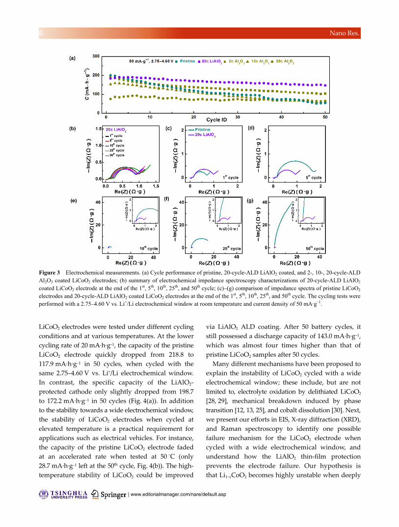
The dilemma mentioned above can be solved by
using a LiAlO2 coating, as shown by the tests conducted
with the 2.75–4.60 V electrochemical window at the
cycling rate of 50 mA·g–1 (Fig. 3(a)). EIS was conducted
under the same test conditions after different numbers
of battery cycles for the LiAlO2 coated LiCoO2 electrode
(Fig. 3(b)). The impedance spectra remained almost
unchanged after 50 cycles, which explained the good
capacity retention of the LiAlO2 coated LiCoO2 electrode
cycled with high voltage cutoffs. The detailed impedance
spectra of the LiAlO2 coated LiCoO2 electrode were also
compared with those of the pristine LiCoO2 electrode
side by side after 1, 5, 10, 25, and 50 battery cycles
(Figs. 3(c)–3(g)). At the end of the 1st charge cycle, the
impedance spectra of both samples with and without
coating comprised two semicircles and a straight line
angled close to 45°. The small semicircle at high
frequency was related to the solid electrolyte interface,
while the one at medium frequency corresponded to
the charge transfer at the cathode/electrolyte interface
[26]. The 45° inclined line at low frequency was due
to the Warburg impedance, which can be attributed
to the diffusion of lithium ions within the LiCoO2
cathode [27]. Upon battery cycling, the semicircle at
medium frequency increased significantly for the
pristine LiCoO2 electrode, indicating the slowdown of
charge transport across the cathode/electrolyte interface.
Although the initial charge transfer resistance was
slightly higher for LiAlO2 thin film coated samples
(Fig. 3(c)), the coating layer helped suppress the fast
impedance increase seen in the following cycles for
pristine LiCoO2 electrodes (Figs. 3(d)–3(g)).
The stabilities of pristine and LiAlO2 coated
| www.editorialmanager.com/nare/default.asp
6 Nano Res.
LiCoO2 electrodes were tested under different cycling
conditions and at various temperatures. At the lower
cycling rate of 20 mA·h·g–1, the capacity of the pristine
LiCoO2 electrode quickly dropped from 218.8 to
117.9 mA·h·g–1 in 50 cycles, when cycled with the
same 2.75–4.60 V vs. Li+/Li electrochemical window.
In contrast, the specific capacity of the LiAlO2-
protected cathode only slightly dropped from 198.7
to 172.2 mA·h·g–1 in 50 cycles (Fig. 4(a)). In addition
to the stability towards a wide electrochemical window,
the stability of LiCoO2 electrodes when cycled at
elevated temperature is a practical requirement for
applications such as electrical vehicles. For instance,
the capacity of the pristine LiCoO2 electrode faded
at an accelerated rate when tested at 50 °C (only
28.7 mA·h·g–1 left at the 50th cycle, Fig. 4(b)). The high-
temperature stability of LiCoO2 could be improved
via LiAlO2 ALD coating. After 50 battery cycles, it
still possessed a discharge capacity of 143.0 mA·h·g–1,
which was almost four times higher than that of
pristine LiCoO2 samples after 50 cycles.
Many different mechanisms have been proposed to
explain the instability of LiCoO2 cycled with a wide
electrochemical window; these include, but are not
limited to, electrolyte oxidation by delithiated LiCoO2
[28, 29], mechanical breakdown induced by phase
transition [12, 13, 25], and cobalt dissolution [30]. Next,
we present our efforts in EIS, X-ray diffraction (XRD),
and Raman spectroscopy to identify one possible
failure mechanism for the LiCoO2 electrode when
cycled with a wide electrochemical window, and
understand how the LiAlO2 thin-film protection
prevents the electrode failure. Our hypothesis is
that Li1−xCoO2 becomes highly unstable when deeply
Figure 3 Electrochemical measurements. (a) Cycle performance of pristine, 20-cycle-ALD LiAlO2 coated, and 2-, 10-, 20-cycle-ALD Al2O3 coated LiCoO2 electrodes; (b) summary of electrochemical impedance spectroscopy characterizations of 20-cycle-ALD LiAlO2
coated LiCoO2 electrode at the end of the 1st, 5th, 10th, 25th, and 50th cycle; (c)–(g) comparison of impedance spectra of pristine LiCoO2
electrodes and 20-cycle-ALD LiAlO2 coated LiCoO2 electrodes at the end of the 1st, 5th, 10th, 25th, and 50th cycle. The cycling tests were performed with a 2.75–4.60 V vs. Li+/Li electrochemical window at room temperature and current density of 50 mA·g–1.

www.theNanoResearch.com∣www.Springer.com/journal/12274 | Nano Research
7 Nano Res.
delithiated at high applied potentials. It could either
self-decompose through disproportionation reactions
or oxidize the electrolyte. Both pathways release
oxygen from the unstable Li1−xCoO2 lattice to form
Co3O4 as one of the side products. The accumulation
of side products increases the impedance of the battery
and leads to a decreased capacity. As discussed earlier,
the EIS measurements (Figs. 3(b)–3(g)) suggested that
the decrease in specific capacity was directly related
to the increase in cell impedance at the cathode/
electrolyte interface. To further validate this assumption,
pristine LiCoO2/Li cells after 50 cycles of battery cycling
were disassembled, and the impedance spectrum
was recorded. Then, all cell components, except the
cycled LiCoO2 electrode itself, were replaced by fresh
ones. As shown in Fig. 5(b), the largest impedance in
a cycled LiCoO2/Li cell was clearly associated with
the cathode. Changing other cell components could
not reduce the already large impedance or restore the
battery capacity.
Through detailed characterization of the electrodes,
the origin of the high measured impedance at the
interface after cycling was identified. After 50 cycles
of aggressive lithiation and delithiation, the LiCoO2
electrode was subjected to XRD examination. In the
case of the cycled electrode, all the peaks identified
in the XRD pattern belonged to the LiCoO2 phase,
and no other significant peaks appeared (Fig. 5(c)),
suggesting that minimum impurities with well-defined
crystalline grain sizes were formed. To detect changes
at the interface, we then conducted ex situ Raman
mapping on pristine and LiAlO2 coated LiCoO2
electrodes after battery cycling. In Fig. 5(d), the
spectrum of a LiAlO2 coated LiCoO2 electrode after
50 battery cycles, mapped using a 532 nm laser, is
shown (more details in the ESM). The Raman spectra
showed two sets of characteristics peaks for LiCoO2
(Co–O stretching (A1g) at 594 cm−1 and O–Co–O
bending (Eg) at 483 cm−1) and carbon (D-band (A1g)
at ~1,355 cm−1 and G-band (E2g2) at ~1,590 cm−1). The
peak positions were in good agreement with the
standard values reported in Ref. [31] and our
measurements from a pristine LiCoO2 electrode prior
to cycling (Fig. S7 in the ESM). The intensity of the
LiCoO2 Eg peak was then integrated and mapped,
and its shape agreed well with the optical images of
Figure 4 Electrochemical measurements. (a) Cycle performance of pristine and 20-cycle atomic layer deposition (ALD) LiAlO2 coatedLiCoO2 electrodes with a current density of 20 mA·g–1 at room temperature; (b) cycle performance of pristine and 50-cycle-ALD LiAlO2
coated LiCoO2 electrodes with a current density of 50 mA·g–1 at elevated temperature (50 °C). Squares indicate Coulombic efficiencies while circles indicate discharge capacities. All cycling tests were performed within a 2.75–4.60 V vs. Li+/Li electrochemical window.

| www.editorialmanager.com/nare/default.asp
8 Nano Res.
the LiCoO2 electrode. When mapping pristine LiCoO2
after cycling (Fig. 5(e)), the most striking difference
was the emergence of Co3O4 peaks. Although
characteristic LiCoO2 and carbon peaks still existed
in some regions, new peaks at 520 and 683 cm−1
emerged in some other regions. These two peaks,
which correspond to one of the three active F2g modes
and one A1g mode of Co3O4, were in good agreement
with those observed in reported Co3O4 Raman spectra
[32] and standard tested Co3O4 Raman spectra (Fig. S7
in the ESM). The intensity of the Co3O4 A1g peak was
integrated and mapped. The results showed that the
formed Co3O4 phase partially overlapped with optical
images of LiCoO2. Upon analysis of the information
gathered, the following hypothesis for the degradation
of the LiCoO2 electrode, when cycled with a wide
electrochemical window, was formulated. The fading
of the LiCO2/Li cell starts at the interface between
LiCoO2 and electrolyte. When deeply delithiated,
LiCoO2 becomes unstable, and could potentially lose
oxygen to form Co3O4. As shown in the supplementary
information, Co3O4 electrodes, even made of Co3O4
nanoparticles with a size of 10–30 nm, were unable to
host lithium ions in the tested 2.75–4.60 V vs. Li+/Li
electrochemical window (Fig. S5 in the ESM). The
formation of the Co3O4 phase has been observed by
other groups as well [33, 34]. For ALD LiAlO2 protected
cathodes, such phase transition from LiCoO2 to
Co3O4 at the interface was not observed. The lack of
phase transition was attributed to the chemical stability
of the LiAlO2 film, which prevented interfacial reactions
between LiCoO2 and electrolyte.
3 Conclusions
In this work, we demonstrated that, by using ALD
to form a LiAlO2 thin-film coating directly on the
LiCoO2 electrode, improved stability over a wide
electrochemical window and at elevated temperature
can be achieved without sacrificing energy density or
power density. The detailed capacity fading mechanism
of the LiCoO2 electrode under aggressive cycling
Figure 5 (a) Schematic illustration of possible fading mechanism of LiCoO2 electrode under high voltage cycling; cyan circles indicateLiCoO2 particles, green circle indicates the surface passivation layer, and violet circle indicates the stable LiCoO2 interfacial layer; (b) electrochemical impedance spectroscopy characterizations of pristine LiCoO2/Li coin cell after 50 cycles (red trace) and reassembled coin cell using the cycled pristine LiCoO2 (blue trace); (c) X-ray diffraction patterns of pristine LiCoO2 electrode prior to cycling (black trace) and pristine LiCoO2 electrode after 50 battery cycles (red trace); (d) Raman mapping of LiAlO2 coated LiCoO2 electrode surface after 50 battery cycles; (e) Raman mapping of pristine LiCoO2 electrode surface after 50 battery cycles. For the Raman mapping, thewhite-highlighted square area in the optical image was mapped.

www.theNanoResearch.com∣www.Springer.com/journal/12274 | Nano Research
9 Nano Res.
conditions was also investigated. The results suggested
that the formation of an inactive interfacial layer
could lead to increased cell impedance and significant
polarization. By encapsulating LiCoO2, the LiAlO2 thin-
film coating shows promising potential for improving
battery stability for high-voltage battery operation.
4 Experimental
4.1 Materials synthesis and preparation
LiCoO2 (MTI Inc., see Fig. S3 in the ESM for more
details), Super C65 (Imerys), and PI (DuPont) were
dried under vacuum for 24 h to remove trapped
moisture prior to use. LiCoO2 working electrodes
were made using a typical slurry method by mixing
LiCoO2, super C65, and PI with a mass ratio of 90:5:5
in N-methyl-pyrrolidone solvent. PI was selected as
the binder instead of PVDF, owing to the high thermal
stability of PI. PVDF has a melting point of 177 °C,
which is well below the ALD operation temperature
of 225 °C. We found that PI-bound electrodes showed
a slightly better cycling stability than PVDF-bound
electrodes (Fig. S8 in the ESM). The average mass
loading of active material (LiCoO2) was 15 mg·cm–2.
For all ALD samples, they were calendared before
ALD coating. For control samples, we also followed
the same calendaring process on pristine LiCoO2
electrodes with exactly the same pressure applied.
LiAlO2 was directly coated on LiCoO2 electrodes
by using a Savannah S100 ALD system (Cambridge
Nanotech). LiAlO2 ALD coating was developed based
on previous literature reports [22]. Typical LiAlO2
ALD coating was prepared by alternating Li2O and
Al2O3 sub-cycles under exposure mode to ensure high
uniformity on high surface area substrates. The
indicated number of ALD cycles in this article was
counted by adding all Li2O and Al2O3 sub-cycles. For
instance, a 20-cycle LiAlO2 ALD consisted of 10 super-
cycles of one Li2O sub-cycle and one Al2O3 sub-cycle.
The pulse, exposure, and purge sequence in a super
cycle for lithium tert-butoxide, water, trimethy-
laluminum, and water was 2 s–20 s–30 s–0.015 s–20 s–
30 s–0.015 s–20 s–30 s–0.015 s–20 s–30 s. For pure Al2O3
ALD, the Li2O sub-cycle was replaced by the Al2O3
sub-cycle. All depositions were performed at 225 °C.
Lithium tert-butoxide was heated to 155–165 °C.
Trimethylaluminum and water were kept at room
temperature.
4.2 Electrochemical measurements
The battery cycling performance was evaluated by
the galvanostatic cycling of coin cells (CR 2032)
with Li foil (Alfa Aesar) as the counter electrode.
The electrolyte consisted of 1.0 M LiPF6 in ethylene
carbonate and diethyl carbonate with 1:1 volume ratio.
Battery cycling data were collected using a LAND
8-channel battery tester with the potential window
of 2.75–4.60 V vs. Li+/Li at room temperature unless
specified. The specific capacity was calculated based
on the weight of LiCoO2. After different numbers
of cycles, coin cells were rested for 5 h prior to EIS
measurements. EIS was conducted using a Biologic
VSP potentiostat over the frequency range of 0.01 Hz
to 1 MHz.
4.3 Material characterization
XRD (PANalytical X’Pert Diffractometer) was employed
for phase identification, using Cu Kα radiation
(0.15406 nm). TEM characterizations were conducted
in a FEI Tecnai G2 F20 X-twin TEM system at an
acceleration voltage of 200 kV. Raman spectroscopy
was performed on a Horiba Labram HR Evolution
Raman System with a 50 mW 532 nm excitation laser.
XPS was performed on PHI 5000 VersaProbe, using
an Al Kα (λ = 0.83 nm; hυ = 1,486.7 eV) X-ray source
operated at 2 kV and 20 mA. Elemental analysis was
conducted using a Thermo Scientific XSERIES 2 ICP-MS
system.
Acknowledgements
Part of this work was performed at the Stanford Nano
Shared Facilities (SNSF) and Stanford Nanofabrication
Facility (SNF). We thank Allen Pei, Yongming Sun,
and Kipil Lim for insightful discussion, Michelle Rincon,
Christopher Neumann and Feifei Lian for technical
assistance.
Electronic Supplementary Material: Supplementary
material (experimental details and additional

| www.editorialmanager.com/nare/default.asp
10 Nano Res.
characterizations) is available in the online version of
this article at https://doi.org/10.1007/s12274-017-1588-1.
References
[1] Johnson, B. A.; White, R. E. Characterization of commercially
available lithium-ion batteries. J. Power Sources 1998, 70,
48–54.
[2] Winter, M.; Besenhard, J. O.; Spahr, M. E.; Novák, P.
Insertion electrode materials for rechargeable lithium batteries.
Adv. Mater. 1998, 10, 725–763.
[3] Goodenough, J. B.; Kim, Y. Challenges for rechargeable Li
batteries. Chem. Mater. 2010, 22, 587–603.
[4] Etacheri, V.; Marom, R.; Elazari, R.; Salitra, G.; Aurbach, D.
Challenges in the development of advanced Li-ion batteries:
A review. Energy Environ. Sci. 2011, 4, 3243–3262.
[5] Tarascon, J. M.; Armand, M. Issues and challenges facing
rechargeable lithium batteries. Nature 2001, 414, 359–367.
[6] Whittingham, M. S. Lithium batteries and cathode materials.
Chem. Rev. 2004, 104, 4271–4301.
[7] Cho, J.; Kim, Y. J.; Park, B. Novel LiCoO2 cathode material
with Al2O3 coating for a Li ion cell. Chem. Mater. 2000, 12,
3788–3791.
[8] Chen, Z. H.; Dahn, J. R. Studies of LiCoO2 coated with metal
oxides. Electrochem. Solid-State Lett. 2003, 6, A221–A224.
[9] Chen, Z. H.; Dahn, J. R. Methods to obtain excellent capacity
retention in LiCoO2 cycled to 4.5 V. Electrochim. Acta 2004,
49, 1079–1090.
[10] Jung, Y. S.; Cavanagh, A. S.; Dillon, A. C.; Groner, M. D.;
George, S. M.; Lee, S. H. Enhanced stability of LiCoO2
cathodes in lithium-ion batteries using surface modification
by atomic layer deposition. J. Electrochem. Soc. 2010, 157,
A75–A81.
[11] Scott, I. D.; Jung, Y. S.; Cavanagh, A. S.; An, Y. F.; Dillon,
A. C.; George, S. M.; Lee, S. H. Ultrathin coatings on
nano-LiCoO2 for Li-ion vehicular applications. Nano Lett.
2011, 11, 414–418.
[12] Cho, J.; Kim, Y. J.; Kim, T. J.; Park, B. Zero-strain intercalation
cathode for rechargeable Li-ion cell. Angew. Chem., Int. Ed.
2001, 40, 3367–3369.
[13] Cho, J.; Kim, Y. J.; Park, B. LiCoO2 cathode material that
does not show a phase transition from hexagonal to monoclinic
phase. J. Electrochem. Soc. 2001, 148, A1110–A1115.
[14] Park, J. S.; Mane, A. U.; Elam, J. W.; Croy, J. R. Amorphous
metal fluoride passivation coatings prepared by atomic layer
deposition on LiCoO2 for Li-ion batteries. Chem. Mater.
2015, 27, 1917–1920.
[15] Jung, Y. S.; Lu, P.; Cavanagh, A. S.; Ban, C. M.; Kim,
G. H.; Lee, S. H.; George, S. M.; Harris, S. J.; Dillon, A. C.
Unexpected improved performance of ALD coated LiCoO2/
graphite Li-ion batteries. Adv. Energy Mater. 2013, 3,
213–219.
[16] Cao, H.; Xia, B. J.; Zhang, Y.; Xu, N. X. LiAlO2-coated
LiCoO2 as cathode material for lithium ion batteries. Solid
State Ionics 2005, 176, 911–914.
[17] Park, J. S.; Meng, X. B.; Elam, J. W.; Hao, S. Q.; Wolverton,
C.; Kim, C.; Cabana, J. Ultrathin lithium-ion conducting
coatings for increased interfacial stability in high voltage
lithium-ion batteries. Chem. Mater. 2014, 26, 3128–3134.
[18] Liu, J.; Banis, M. N.; Li, X. F.; Lushington, A.; Cai, M.; Li,
R. Y.; Sham, T. K.; Sun, X. L. Atomic layer deposition of
lithium tantalate solid-state electrolytes. J. Phys. Chem. C
2013, 117, 20260–20267.
[19] Mäntymäki, M.; Hämäläinen, J.; Puukilainen, E.; Sajavaara,
T.; Ritala, M.; Leskela, M. Atomic layer deposition of LiF
thin films from Lithd, Mg(thd)2, and TiF4 precursors. Chem.
Mater. 2013, 25, 1656–1663.
[20] Kozen, A. C.; Pearse, A. J.; Lin, C. F.; Noked, M.; Rubloff,
G. W. Atomic layer deposition of the solid electrolyte LiPON.
Chem. Mater. 2015, 27, 5324–5331.
[21] Glass, A. M.; Nassau, K. Lithium ion conduction in rapidly
quenched Li2O-Al2O3, Li2O-Ga2O3, and Li2O-Bi2O3 glasses.
J. Appl. Phys. 1980, 51, 3756–3761.
[22] Aaltonen, T.; Nilsen, O.; Magrasó, A.; Fjellvåg, H. Atomic
layer deposition of Li2O-Al2O3 thin films. Chem. Mater. 2011,
23, 4669–4675.
[23] Hu, Y.; Ruud, A.; Miikkulainen, V.; Norby, T.; Nilsen, O.;
Fjellvag, H. Electrical characterization of amorphous LiAlO2
thin films deposited by atomic layer deposition. RSC Adv.
2016, 6, 60479–60486.
[24] George, S. M. Atomic layer deposition: An overview. Chem.
Rev. 2010, 110, 111–131.
[25] Wang, H. F.; Jang, Y. I.; Huang, B. Y.; Sadoway, D. R.;
Chiang, Y. M. TEM study of electrochemical cycling-induced
damage and disorder in LiCoO2 cathodes for rechargeable
lithium batteries. J. Electrochem. Soc. 1999, 146, 473–480.
[26] Levi, M. D.; Salitra, G.; Markovsky, B.; Teller, H.;
Aurbach, D.; Heider, U.; Heider, L. Solid-state electrochemical
kinetics of Li-ion intercalation into Li1–xCoO2: Simultaneous
application of electroanalytical techniques SSCV, PITT,
and EIS. J. Electrochem. Soc. 1999, 146, 1279–1289.
[27] Ho, C.; Raistrick, I. D.; Huggins, R. A. Application of A-C
techniques to the study of lithium diffusion in tungsten
trioxide thin films. J. Electrochem. Soc. 1980, 127, 343–350.
[28] Thomas, M. G. S. R.; Bruce, P. G.; Goodenough, J. B. AC
impedance of the Li(1–x)CoO2 electrode. Solid State Ion. 1986,
18–19, 794–798.
[29] Thomas, M. G. S. R.; Bruce, P. G.; Goodenough, J. B. AC

www.theNanoResearch.com∣www.Springer.com/journal/12274 | Nano Research
11 Nano Res.
impedance analysis of polycrystalline insertion electrodes:
Application to Li1–xCoO2. J. Electrochem. Soc. 1985, 132,
1521–1528.
[30] Amatucci, G. G.; Tarascon, J. M.; Klein, L. C. Cobalt
dissolution in LiCoO2-based non-aqueous rechargeable
batteries. Solid State Ion. 1996, 83, 167–173.
[31] Baddour-Hadjean, R.; Pereira-Ramos, J. P. Raman micro-
spectrometry applied to the study of electrode materials for
lithium batteries. Chem. Rev. 2010, 110, 1278–1319.
[32] Hadjiev, V. G.; Iliev, M. N.; Vergilov, I. V. The Raman
spectra of Co3O4. J. Phys. C: Solid State Phys. 1988, 21,
L199–L201.
[33] Park, Y.; Kim, N. H.; Kim, J. M.; Kim, Y. C.; Jeong, Y. U.;
Lee, S. M.; Choi, H. C.; Jung, Y. M. Surface reaction of
LiCoO2/Li system under high-voltage conditions by X-ray
spectroscopy and two-dimensional correlation spectroscopy
(2D-COS). Appl. Spectrosc. 2011, 65, 320–325.
[34] Park, Y.; Kim, N. H.; Kim, J. Y.; Eom, I. Y.; Jeong, Y. U.;
Kim, M. S.; Lee, S. M.; Choi, H. C.; Jung, Y. M. Surface
characterization of the high voltage LiCoO2/Li cell by X-ray
photoelectron spectroscopy and 2D correlation analysis. Vib.
Spectrosc. 2010, 53, 60–63.