engineering technical training modules for nuclear plant
TRANSCRIPT
WARNING:Please read the License Agreementon the back cover before removing the Wrapping Material
Engineering Technical Training Modules for Nuclear Plant Engineers
Mechanical Series: Module #11
Relief and Safety Valves
1010789


Engineering Training Modules for Nuclear Plant EngineersMechanical Series: Module #11
Relief and Safety Valves
1010789
Technical Report, October 1999
EPRI Project Manager(s)
T. Eckert
M. Hooker

EPRI • 3412 Hillview Avenue, Palo Alto, California 94304 • PO Box 10412, Palo Alto, California 94303 • USA800.313.3774 • 650.855.2121 • [email protected] • www.epri.com

DISCLAIMER OF WARRANTIES AND LIMITATION OF LIABILITIES
THIS DOCUMENT WAS PREPARED BY THE ORGANIZATION(S) NAMED BELOW AS AN ACCOUNT OF WORK SPONSORED OR COSPONSORED BY THE ELECTRIC POWER RESEARCH INSTITUTE, INC. (EPRI). NEITHER EPRI, ANY MEMBER OF EPRI, ANY COSPONSOR, THE ORGANIZATION(S) BELOW, NOR ANY PERSON ACTING ON BEHALF OF ANY OF THEM:
(A) MAKES ANY WARRANTY OR REPRESENTATION WHATSOEVER, EXPRESS OR IMPLIED, (I) WITH RESPECT TO THE USE OF ANY INFORMATION, APPARATUS, METHOD, PROCESS, OR SIMILAR ITEM DISCLOSED IN THIS DOCUMENT, INCLUDING MERCHANTABILITY AND FITNESS FOR A PARTICULAR PURPOSE, OR (II) THAT SUCH USE DOES NOT INFRINGE ON OR INTERFERE WITH PRIVATELY OWNED RIGHTS, INCLUDING ANY PARTY'S INTELLECTUAL PROPERTY, OR (III) THAT THIS DOCUMENT IS SUITABLE TO ANY PARTICULAR USER'S CIRCUMSTANCE; OR
(B) ASSUMES RESPONSIBILITY FOR ANY DAMAGES OR OTHER LIABILITY WHATSOEVER (INCLUDING ANY CONSEQUENTIAL DAMAGES, EVEN IF EPRI OR ANY EPRI REPRESENTATIVE HAS BEEN ADVISED OF THE POSSIBILITY OF SUCH DAMAGES) RESULTING FROM YOUR SELECTION OR USE OF THIS DOCUMENT OR ANY INFORMATION, APPARATUS, METHOD, PROCESS, OR SIMILAR ITEM DISCLOSED IN THIS DOCUMENT.
ORGANIZATION(S) THAT PREPARED THIS DOCUMENT
EPRI
This is an EPRI Technical Update report. A Technical Update report is intended as an informal report of continuing research, a meeting, or a topical study. It is not a final EPRI technical report.
ORDERING INFORMATION
Requests for copies of this report should be directed to EPRI Orders and Conferences, 1355 Willow Way, Suite 278, Concord, CA 94520. Tollfree number: 800.313.3774, press 2, or internally x5379; voice: 925.609.9169; fax: 925.609.1310.
Electric Power Research Institute and EPRI are registered service marks of the Electric Power Research Institute, Inc. EPRI. ELECTRIFY THE WORLD is a service mark of the Electric Power Research Institute, Inc.
Copyright © 2005 Electric Power Research Institute, Inc. All rights reserved.


EPRI Licensed Material
TABLE OF CONTENTS
1.0 SCOPE AND PURPOSE . . . . . . . . . . . . . . . . . . . . . . . . . . . . . . . . . . . . .. . . . .
3
2.0 SUGGESTED SKILLS AND KNOWLEDGE . . . . . . . . . . . . . . . . . . . . . . . . . . 5
3.0 OBJECTIVES . . . . . . . . . . . . . . . . . . . . . . . . . . . . . . . . . . . . . . . . . . . . . . . . .
7
4.0 NOMENCLATURE . . . . . . . . . . . . . . . . . . . . . . . . . . . . . . . . . . . . . . . . . . . . .
9
5.0 PRINCIPLES AND PROPERTIES . . . . . . . . . . . . . . . . . . . . . . . . . . . . . . . . . . .
13
5.1 Operation of Relief Valves . . . .. . . . . . . . . . . . . . . . . . . . . . . . . . . . . . . . 13
5.2 Safety Valves . . . . . . . . . . . . . . . . . . . . . . . . . . . . . . . . . . . . . . . . . . . . . . . . 14
5.3 SafetyRelief Vavles . . . . . . . . . . . . . . . . . . . . . . . . . . . . . . . . . . . . . . . . . . 16
5.4 PowerOperated Relief Valves. . . . . . . . . . . . . . . . . . . . . . . . . . . . . . . . . . . 16
5.5 ValvePerformance Requirements . . . . . . . . . . . . . . . . . . . . . . . . . . . . . . . . 17
5.6 Relieving Valve Sizing . . . . . . . . . . . . . . . . . . . . . . . . . . . . . . . . . . . . . . . . 19
5.7 Relieving Valve Design Considerations . . . . . . . . . . . . . . . . . . . . . . . . . . . 26
5.8 Valve/System Interactions . . . . . . . . . . . . . . . . . . . . . . . . . . . . . . . . . . . . . . 28
5.9 Pressure Relieving Valve Testing Requirements . . . . . . . . . . . . . . . . . . . . . 29
6.0 NUCLEAR CONSIDERATIONS . . . . . . . . . . . . . . . . . . . . . . . . . . . . . . . . . . . 37
7.0 UTILITY EXAMPLE EXERCISES AND SOLUTIONS . . . . . . . . . . . . . . . . . . . 39
1

EPRI Licensed Material
8.0 SOURCE DOCUMENTATION . . . . . . . . . . . . . . . . . . . . . . . . . . . . . . . . . . . . .
43
9.0 INDUSTRY OPERATING EXPERIENCE . . . . . . . . . . . . . . . . . . . . . . . . . . . . . 45
10.0 PROFICIENCY MEASURES . . . . . . . . . . . . . . . . . . . . . . . . . . . . . . . . . . . . . .
47
2

EPRI Licensed Material
1

EPRI Licensed Material
1.0 SCOPE AND PURPOSE
Pressure relieving valves (relief, safety and safetyrelief valves) are used throughout the nuclear power generating industry to provide overpressure protection of pressurized systems. These valves normally operate automatically, on sensing the increased system pressure, but in many models, can be operated manually as well. This module provides an overview of the operation of relief and safety valves in nuclear power generating plants and the associated maintenance and testing requirements.
2

EPRI Licensed Material
3

EPRI Licensed Material
2.0 SUGGESTED SKILLS AND KNOWLEDGE
It is suggested that the student understand the fundamentals of fluid mechanics and hydraulics.
4
EPRI Licensed Material
5

EPRI Licensed Material
3.0 OBJECTIVES
The objective of this training module is to familiarize the student with the following principles, properties and applications. At the conclusion of this module, the student will describe:
• Function and Application of Relief and Safety Valves
• Materials Used in the Valve Construction
• ASME XI Test Requirements
• Valve Sizing
• Simplified analysis to determine the forces to open and close relief valves
6
EPRI Licensed Material
7

EPRI Licensed Material
4.0 NOMENCLATURE
4.1 Symbols and Abbreviations
A = crosssectional area of the safety valve nozzle throat Cv = valve flow coefficient
g = acceleration of gravity
Kb = capacity correction factor due to back pressure, used in the sizing equations of safety relief valve for gas or vapor service
KD = coefficient of discharge of pressure relief valves, expressing the ratio of the actual measured relieving capacity to the theoretical relieving capacity, based on the nominal flow area
F↑o = Opening Force
Ds = Sealing Diameter
DK = Piston Diameter
P1 = Static Inlet Fluid Pressure
F↓o = Initial Closing Force
H = Compression displacement of the main spring (equal to the disc lift)
k = Spring Constant
Dstem = Stem Diameter
Pz = Pressure above piston (backpressure)
w = rated flow saturated steam
a = actual discharge area through the valve developed lift
P = (set pressure x 1.03) plus atmospheric pressure
K = coefficient of discharge = 0.9 KD
4.2 Definitions
Maximum Allowable working Pressure: Maximum Allowable Working Pressure (MAWP) is the highest or lowest pressure a vessel is expected to be exposed to during various operating
8

EPRI Licensed Material
conditions. The vessel may not be operated outside these set conditions. Consequently, this is the highest or lowest pressure at which the primary pressure relieving valve is set to open.
Set Pressure: Set pressure is the inlet pressure at which the pressure relieving valve starts to discharge under service conditions. Set pressure is normally measured in pounds per square inch gauge.
Accumulation: Pressure increase over the MAWP of the vessel during discharge through the valve. It is expressed as a percentage (eg. 10% accumulation). Consequently, it is the increase in pressure above MAWP that occurs.
Overpressure: Pressure increase or decrease beyond the set pressure of the primary relieving device. Overpressure is the same as accumulation when the relieving device is set to open at the MAWP of the vessel.
Blowdown: Blowdown is the difference between the set pressure (“popping” pressure) and the resetting pressure of a pressure relieving valve. This pressure is commonly expressed as a percentage of the set pressure such as 5% Blowdown. Another way of describing blowdown is to say that it is the difference between set pressure of the valve and system pressure when the valve recloses.
Sequential Lift Series: Sequential lift series applies when there is more than one pressure relieving device in the system. It is an important concept to understand since ASME codes dictate the percentage of operating pressure at which the first relieving device must open (e.g. 105%, 107%, etc.) and the required capacity which all the relieving devices must have when open.
Simmer: Simmer is leakage between the seat and disc just prior to the valve opening.
Nozzle: The nozzle performs three functions:
• Acts as the valve seat
• Directs the flow under the valve disc
• Controls the rate that fluid is allowed to escape from the system.
Adjusting Rings: Adjusting rings regulate blowdown and simmer. Rings vary from one manufacturer to another; some have upper and lower rings while many have only a lower ring.
9
EPRI Licensed Material
Adjusting ring(s) affect simmer and blowdown since a change in position changes/alters the effective area that fluid acts upon.
Blowdown Adjustment: If the valve has both upper and lower adjusting rings, altering the position of the upper ring changes the size of the huddling chamber giving a greater/lesser percentage of blowdown when the valve opens.
If one lower adjusting ring is used, repositioning it adjusts the nozzling effect on the fluid. It then increases or reduces the amount of fluid focused on the disc assembly and the length of time the fluid is held in the nozzle and disk area. This increases or reduces the amount of upward force and results in a greater or lesser percentage of blowdown.
Huddling Chamber: A ring shaped pressure chamber located beyond the valve seat diameter. It gives safety and safety-relief valves a “popping” action by providing additional surface area once the valve initially comes off its seat.
10

EPRI Licensed Material
11

EPRI Licensed Material
5.0 PRINCIPLES AND PROPERTIES
Pressure relieving valves play an important role in the protection of station systems, components and personnel. In order to do this, these valves must perform two important functions. Pressure relieving valves must:
• Relieve overpressure conditions
• Control system volume
Pressure relieving valves are used in virtually all piping systems throughout the station. These include systems that are common to nuclear generating stations such as:
• Primary Coolant
• Component Cooling Water
• Main and Auxiliary Feedwater
• Service Water
• Demineralized Water Makeup
• Filtered Water
• Station and Instrument Air
• Main and Auxiliary Steam
5.1 Operation of Relief Valves
Relief valves are pressure relieving devices actuated by the static pressure upstream of the device. They open in proportion to the increase in pressure over the valve set pressure and are used primarily in liquid service. Relief valves function in the following manner. First, an initial downward force is applied by compressing a spring with an adjusting screw. When system pressure increases, upward force on the disc is developed. As long as downward force applied by spring load is greater than upward force created by the fluid acting on the disc area, the valve will remain closed. Also, valve opening will be proportional to overpressure since the disc area that fluid is acting upon remains the same.
12

EPRI Licensed Material
Relief valves do not need a large opening to relieve overpressure as do safety valves since the fluid being discharged does not expand. System pressure drops rapidly once valve discharge begins. Therefore, slow opening is acceptable in liquid service applications. As the inlet pressure reaches the valve set pressure, the disc lifts a minimal amount and small steady stream of fluid begins to flow. When the pressure begins to decrease, the flow and the lift decrease until the valve closes at a pressure at or below the set point.
Relief valves are normally designed with a closed bonnet. The bonnet is usually vented to the discharge side of the valve to avoid adverse effects on the performance of the valve. The set pressure of the relief valve is determined by the force of the spring acting on the disc and the back pressure on the valve. The amount of the backpressure effect is directly proportional to the area exposed to the backpressure.
Figure 1: Relief Valve
Disk
13

EPRI Licensed Material
5.2 Safety Valves
Safety valves are pressure relieving devices actuated by the inlet static pressure and are characterized by rapid opening or “popping” action. Safety valves may be springloaded or pilotactuated. In the springloaded design, the force of the system pressure on the disc is opposed by a main spring. In the pilotactuated design, the system pressure acts on a small pilot valve, which opens at the set point of the valve and creates a pressure imbalance in the main valve, causing the main disc to open. Both types of valves actuate automatically when the fluid pressure in the protected system reaches a predetermined set pressure. Safety valves are used on steam, gas and vapor services. Since the fluid contained is compressed, a larger valve opening is required to achieve a given pressure drop in the system. The "popping" characteristic results since the fluid being discharged is acting on a larger disc area when the valve opens and suddenly expanding to a larger volume. Safety valves have essentially two disc areas for fluid to act upon. The "initial" area corresponds to the inside diameter of the nozzle. The "final" area is larger, therefore, more upward force is created as the valve begins to discharge fluid.
They are designed to mitigate pressure rise in the system to below a defined design value. Subsequent to the pressure transient, the safety valve reseats and is prepared to provide pressure relief again, if required.
Many safety valves vents the spring housing to the discharge side of the valve. The operational characteristics are directly affected by changes in the backpressure on the valve. A balanced safety valve incorporates a bellows assembly to minimize the effects of backpressure on its operational characteristics.
Safety valves are used for compressible fluid service when large volumes are required to be exhausted for pressure relief.
D
Nozzl
Nozzle Ring
Figure 2: Safety Valve
Test levers allow for manually lifting pressure relief for test purposes or PM's.
Huddling
14

EPRI Licensed Material
5.3 SafetyRelief Valves
Safetyrelief valves are pressure relieving devices actuated by the inlet static pressure and characterized by rapid opening or “popping” action, or by opening in proportion to the increase in pressure over the opening pressure, depending on application. Safetyrelief valves can be used for either liquid or compressible fluid service. The primary difference between a safetyrelief valve and a safety valve is that the safetyrelief valve has a fluidtight bonnet, allowing it to be used for liquid service. Similar to the safety valve, safetyrelief valves may be springloaded or pilotactuated.
A variation of the safetyrelief valve is the “balanced safetyrelief valve”. In this design, the uncompensated area of the disc is isolated from the backpressure by a bellows, which is vented to the atmosphere.
D
NozzlNozzle
Figure 3: SafetyRelief Valve
15

EPRI Licensed Material
5.4 PowerOperated Relief Valves
Poweroperated relief valves (PORVs) are pressure relieving devices which require an external power supply for actuation. These valves are typically controlled by an electrical signal resulting from high system pressure or manually from the control room. The electrical signal initiates the relief action by activating the valve actuator, either electrically or pneumatically. The primary function of PORVs is to inhibit pressure increases due to anticipated operational transients, and minimize the probability of safety or safetyrelief valve actuation by mitigating pressure rise. PORVs are commonly used in steam and primary side applications in nuclear power plants.
5.5 Valve Performance Requirements
In order to establish performance requirements and then to properly size a valve, it is necessary to determine the fluid parameters being contained by the valve and consider other interactions that could affect valve operations. Fluid parameters are important factors in choosing the best valve for the application. These parameters will influence the choice of the valve type and size, the valve body, seat, and disc material.
16

EPRI Licensed Material
5.5.1 Flow Media
Flow media chemistry will determine the type of material used for the valve body and other wetted parts. A highly corrosive media will require careful consideration of the valve type and the materials used. At nuclear power plants, the potential for leakage from a valve of radioactive fluid or a combustible gas such as hydrogen requires special consideration in valve selection and application.
5.5.2 Pressure/Temperature
System design pressure and temperature are based on the most severe conditions expected during system operation. These design conditions are used to determine the primary valve pressure rating. The adjusted pressure/temperature rating tables given in ANSI B16.34 and B16.5 list the maximum allowable working pressures for a given temperature. The maximum operating temperature may be limited to temperature lower than that specified in the pressure/temperature rating table if elastomers are used for the seats and seals. This restriction is described in the applicable code.
5.5.3 Fluid Density, Specific Volume, and Specific Gravity
Density or specific gravity of the fluid must be considered if the pressure drop is calculated using the Cv coefficient (Cv is defined based on flow of water at 60oF). The density of the fluid changes with temperature, but very little with pressure unless very high pressures are being considered. The densities of gasses and vapor, however, are greatly affected by pressure changes.
5.5.4 Radiation
Elastomers and synthetics are commonly used in valve construction for seats, seals, liners, and sleeves. They have a lower resistance to radiation than metals. Therefore, if elastomers or synthetics are considered for use in valves which will be exposed to long term radiation exposure, the total integrated dose (TID) must be specified to establish the valve design basis. TID, temperature and flow media chemistry, will determine the type of elastomer is best suited for the application and its service life.
5.5.5 Fluid Transients
Dynamic fluid effects such as water hammer, flashing, and cavitation, and thermal shock initiated from operation of either the valve or the system must be considered
Water hammer is the dynamic effect caused by rapid acceleration, deceleration, or flow reversal of a mass of liquid. Severe water hammer may be cause by:
• Steam pocket collapse in a pipe upon injection of steam into subcooled water.
• Steam and subcooled water interactions in horizontal pipes.
17

EPRI Licensed Material
• Subcooled water drawn into a collapsing steam-filled vertical pipe.
• Hot water entering a lower pressure line resulting in a steam bubble flash and subsequent collapse.
• Steam-propelled water slug flow.
• Rapid valve operation
• Water column separation and rejoining.
Normal transients that should be accommodated in the valve design, include:
• Pump start with inadvertently voided discharge lines.
• Rapid valve opening, closing, or instability.
• Water entrainment in steam lines caused by steam line control or safety valves opening with condensed steam in the line.
Cavitation is a phenomenon that usually occurs in systems where liquid velocities are high, and pressures are near the saturation pressures of the liquid in the system. When the velocity of the liquid increases at sudden changes of pipe cross section (at sharp bends, at throttle valves, or in other similar situations), the localized liquid pressure drops below the vapor pressure of the liquid, and the liquid will flash. The flowing stream now consists of liquid plus pockets of vapor. As the liquid flows back to regions of higher pressure, the pockets of vapor collapse. It is the collapse of the vapor pockets which causes the damage. Although mild cavitation is of little concern, severe cavitation can destroy valves and piping and must be avoided.
Flashing occurs when a liquid is reduced in pressure below its vapor pressure. Flashing may occur in a valve when the liquid passes through a restriction and then expands again. When this condition exists, vapor bubbles form and the result in two-phase flow.
Thermal shock results from the rapid heating or cooling of metals. It is usually the result of rapid realignment of systems or portions of systems, disturbance of thermal stratification, or operation of pressure relief devices. In nuclear power plants it may not be possible to eliminate thermal transients during certain plant conditions due to operational sequences which require safety systems to operate rapidly to mitigate or prevent more serious conditions. Severe thermal transients can affect valve operability by distorting the working parts, causing binding and sometimes incomplete stroking.
5.6 Relieving Valve Sizing
In selection and sizing of a relief valve, it is necessary to determine all potential sources of overpressure and then calculate the fluid removal rate under emergency conditions to maintain the pressure within allowable limits. The ASME B&PV Code provides rules for the design, manufacture, capacity certification, selection, and application of pressure devices used to protect fired and unfired pressure vessels. This section specifically deals with the requirements of overpressure protection in Section III.
18

EPRI Licensed Material
5.6.1 Overpressure Protection
The principal design basis for pressure vessels is the safe containment of design pressure. Protection against overpressure is a very important aspect of pressure vessel design. Proper selection, use, location, and maintenance of relief valves are also essential to protect personnel and equipment as well as to comply with codes and laws.
5.6.2 Determining Required Relieving Capacity
The design of the proper pressure relief valve must take into consideration all of the following upset conditions for the individual equipment if such an upset can occur:
• Blocked discharge
• Fire exposure
• Tube ruptures
• Control valve failure
• Thermal expansion
• Utility or auxiliary service failure
Each upset condition must be carefully evaluated to determine the worst case condition that will dictate the relieving capacity.
The first step in selecting a pressure relief valve for a vessel or system is to determine the required relieving capacity. This requires that all sources of fluid flow and energy into the system be considered and evaluated. Sources of energy might be heat, fire, chemical reaction, etc. Sources of fluid flow could include pumps, compressors, stuck open reducing valves, malfunctioning control valves or inadvertent valve operation, failure of internal heat exchanger tube, or a combination of these types of events. All of these events must be taken into account to determine the worse case overpressure condition. ASME B&PV Code Section III, Article N(X)-7000 provides a comprehensive set of rules for overpressure protection of nuclear plant components. The rules require an analysis of all conditions that could cause overpressure and an analysis of pressure transient conditions. For each plant or installation, this analysis is captured in a document known as the Overpressure Protection Report.
5.6.3 Determining Set Pressure
Section III limits the overpressure to 10% or 3 psi, whichever is greater, above design pressure for most systems of any component within the systems pressure retaining boundary.
After the relieving capacity and allowable overpressure have been established, the next step is to determine the set pressure of the safety or relief valve. The rule for setting
19

EPRI Licensed Material
safety and relief valves is that at least one device be set to open at or below the design pressure of the system or vessel being protected. When more than one safety or relief valve is used, the additional valves may be set at slightly higher pressures. This allowable increase in set pressure over MAWP varies throughout the Code depending on the application and circumstances. In all cases, the valves must open fully and relieve their rated capacity at a pressure equal to, or below the system allowable overpressure.
Section III requires at least one pressure relieving valve be set at or below the design pressure. Additional devices may be set at slightly higher pressures, so long as the maximum overpressure does not exceed 10% of the design pressure when all relieving valves are discharging.
Section VIII requires one safety or relief valve be set at or below MAWP. If additional safety and relief valves are used, they may be set up to 5% above MAWP. The section further allows as supplemental valve added to a vessel to protect against hazard due to fire to be set up to 10% above MAWP.
5.6.4 Determining Blowdown
A pressure relieving valve will generally not reseat until the inlet pressure is reduced to below the set pressure. The difference between actual opening pressure and reseating pressure is called blowdown.
Section III allows 5-7% blowdown for safety valves unless a different value is allowed and specified in the valve design specification. For other types of valves, blowdown is specified in the design specification.
Section VIII has no blowdown requirements for valves as they are shipped from the manufacturer.
20

EPRI Licensed Material
5.6.5 Selecting Pressure Relieving Valves
When the required relieving capacity has been established and the allowable set pressure and overpressure determined, the pressure relieving devices can then be selected. The choice of device is limited to those permitted by the particular code section covering the service in question.
The most widely accepted pressure relieving valve by the various Sections of the Code is the spring-loaded pressure relieving valve, either balanced or conventional. Traditionally, spring-loaded valves for boiler or steam application have been called safety valves, while spring-loaded valves for liquid service have been called relief valves, and multi-purpose spring-loaded valves that are used for steam, other compressible fluids, or liquid, have been called safety-relief valves.
A spring-loaded relief valve is permitted by all sections of the Code as an overpressure protection device. Operational and construction requirements, however, vary among the sections.
A type of auxiliary device used on spring-loaded and pilot valves is the auxiliary actuating device that assists the valve to open and then allows the valve to reseat normally. When the valve is called upon to open, the assist device is actuated, opening the pressure relieving valve by mechanical means. When a safe pressure is restored, the assist device is deactivated and the valve closes normally. If the assist device should fail to operate, there is no interference with the normal operation of the valve.
A second type of pressure relieving valve is the pilot-operated valve. This is a valve in which the major relieving device or main valve is combined with and controlled by a self-actuated auxiliary pressure relieving valve, or pilot. The main valve consists of a nozzle and a disc similar to the conventional spring-loaded except that the disc is held in place by system pressure. When the system pressure rises above the set pressure of the valve, the pilot senses that pressure and vents the pressure above the disc allowing the main valve to open. Pilot-operated pressure relieving valves have the advantage that their operation is less influenced by fluid conditions at the valve inlet; they generally can be tested in situ, and a high seating load is maintained up to the opening point of the valve. The valve has more operating parts, however, and because of the typically small passages in the pilot, the cleanliness of the fluid on which this type of valve operates could become a concern. Sections III and VIII permit pilot-operated pressure relieving valves.
Another type of pressure relieving valve is the power-actuated valve. These valves depend upon an external energy source provided by electrical, pneumatic, or hydraulic systems and generally operate n response to signals from pressure or temperature-sensing devices. This type of pressure relieving valve offers the benefits of a wide variety of control systems but has the disadvantage of relying on an external source of power that may fail under emergency conditions. Power-actuated relieving valves are often furnished on drum type boilers as a convenience to the operators, even though for that type of boiler Section I permits no credit for their relieving capacity. Power-actuated
21

EPRI Licensed Material
pressure relieving valves are permitted by Sections I and III, provided they are used in addition to self-actuated pressure relieving valves in Section I service and provided that redundant controls and energy sources are included for Section III service.
5.6.6 Relieving Valve Operational Characteristics
The following explains the operational characteristics, Code definitions, and how they are applied to relieving valve designs.
5.6.6.1 Set Pressure and Lift
The relieving valve set pressure is the pressure where the valve disc has measurable movement in the opening direction to (lift) due to an inlet pressure. The valve lift begins when the inlet fluid pressure has increased to the point where the upward fluid force begins to exceed the downward force on the disc. In a spring-loaded, self-actuated pressure relieving valve, the set pressure or opening characteristics will vary depending upon the service fluid. For compressible fluid such as air, gas and steam, the valve will open with a “popping” action. For a non-compressible fluid, such as water, opening will occur with minimal disc lift, causing the valve to discharge a small, steady stream of liquid that increases with the inlet pressure. Depending upon the design of the control passage, the disc lift may increase substantially at a pressure value above the opening pressure with an equally substantial increase n flow rate and then increase further to the rated lift at the desired overpressure.
The ASME Codes, Section I and VIII and Subsections of ASME Section III NB, NC, ND, and NE and valve design specifications require that pressure relieving valves open within certain set pressure tolerance limits depending upon valve service requirements and set pressure value.
Ambient temperatures can affect the valve's set pressure profile. Large ambient temperature transients may cause the valve to open outside expected lift set pressure tolerance. The valve setpoint should be tested at the opening ambient conditions of the valve. However, if the valve is tested at room ambient conditions, a correction factor should be applied.
Other variables that may affect the actual set pressure of the valve include:
• The physical condition of the valve and its parts including the condition of the valve seat
• The maintenance practices related to the valve.
• The testing practices related to the valve.
• The physical environment of the installed condition of the valve (such as ambient and fluid temperature, vibration, back pressure on conventional non-balance valves, etc.)
22

EPRI Licensed Material
5.6.6.2 Reseat Pressure and Blowdown
Pressure relieving valves, after opening, normally close at a pressure that is below its setpoint and/or actual opening pressure and above the system's normal operating pressure. Closing pressure is a value of inlet static pressure at which the disc reestablishes contact with the seat. The actual value of closing or reseat pressure is used with the actual valve opening pressure to calculate blowdown. Blowdown can be expressed in pressure units or percent and is calculated as follows:
Eq. 1
( ) 100xpressureset
pressureclosingactualpressuresetactualBlowdownPercent
−=
Eq. 2( ) pressureclosingactualpressuresetactualunitspressureBlowdown −=
The blowdown requirements and or reseating requirements for pressure relieving valves vary depending upon the valve set pressure value and the valve service conditions. Consequently, the user should understand these requirements.
Factors that can affect valve reseat pressure and blowdown are:
• Improper setting of the valve control ring
• Changes in fluid and fluid temperature
• Improper testing practices
• Improper installation of the valve
5.6.6.3 Overpressure and Capacity
Overpressure is a pressure increase at the valve inlet that exceeds the set pressure of a pressure relieving valve is usually expressed as a percent of set pressure. That is if a pressure relieving valve opened at 1000 psig to relieved fluid at 10 percent overpressure, the inlet fluid pressure at the valve inlet would be 1100 psig.
The relieving capacity of pressure relieving valves is determined and rated at an overpressure permitted by the applicable code or regulation to which the valve is rated capacity certified. Codes and standards credit each valve design with a portion of the actual measured capacity. In nuclear power plants, pressure relieving valves are usually designed and manufactured to ASME Codes Sections I, III, and VIII. These Codes specify the overpressure at which the valve design is capacity rated and provides formulas for establishing the portion of the actual measured flow that is used as its rated capacity. It is this capacity (rated relieving or nameplate marked capacity) that is used as a basis for the selection and application of a pressure relieving valve for overpressure protection of a vessel or system.
23

EPRI Licensed Material
To obtain a capacity certification such as ASME, the manufacturer submits the information on the valve design advising the ASME of the Code section and fluid to be used. The valve design is then performance and capacity tested to the requirements of this Code and in accordance with safety and relief valve performance and test code ASME OM-1/ANSI PTC-25. After tests are successfully completed on that fluid, a coefficient of discharge is established. This coefficient may be derated depending upon the Code requirements. It is this value that is used with the ASME formula to calculate the rated capacity.
The following is a typical formula for an ASME Section III Class 1 full-lift safety valve on steam service (below 1500 psig). The formula is used to determine the valve's rated capacity after being certified (see ASME Section III, SubSection NB, Article NB-7000).
Eq. 3aPKw 45.51=
Note: The Code or standard under which the valve is manufactured must be used to determine the rated capacity.
5.6.6.4 Chatter and Flutter
Pressure relieving valves are designed to operate without chatter and flutter. Chatter is defined as the rapid reciprocating motion of the movable parts where the disc contacts the seat. Flutter is the same as chatter, but the disc does not contact the seat. Chatter or flutter during valve operation can cause damage to the valve internals and can occur on opening or closing. Chatter or flutter can be system or mechanically caused.
System caused malfunctions are usually a result of poor inlet piping design or installation of the valve in a poor location. A pressure relieving valve on opening will cause a rapid pressure decay at the valve inlet. Since the valve is a force-balanced device, the pressure decays rapidly below the valve's normal closing pressure, causing the disc lift to be reduced and the disc to move to the closed position. Because system pressure has not been reduced to a level that will permit complete disc closure, increased pressure at the valve inlet will cause the valve to reopen. When this occurs, increased pressure at the valve inlet will cause the valve to reopen. When this occurs, the inlet piping to the valve should be reviewed for pressure losses and restrictions.
24
EPRI Licensed Material
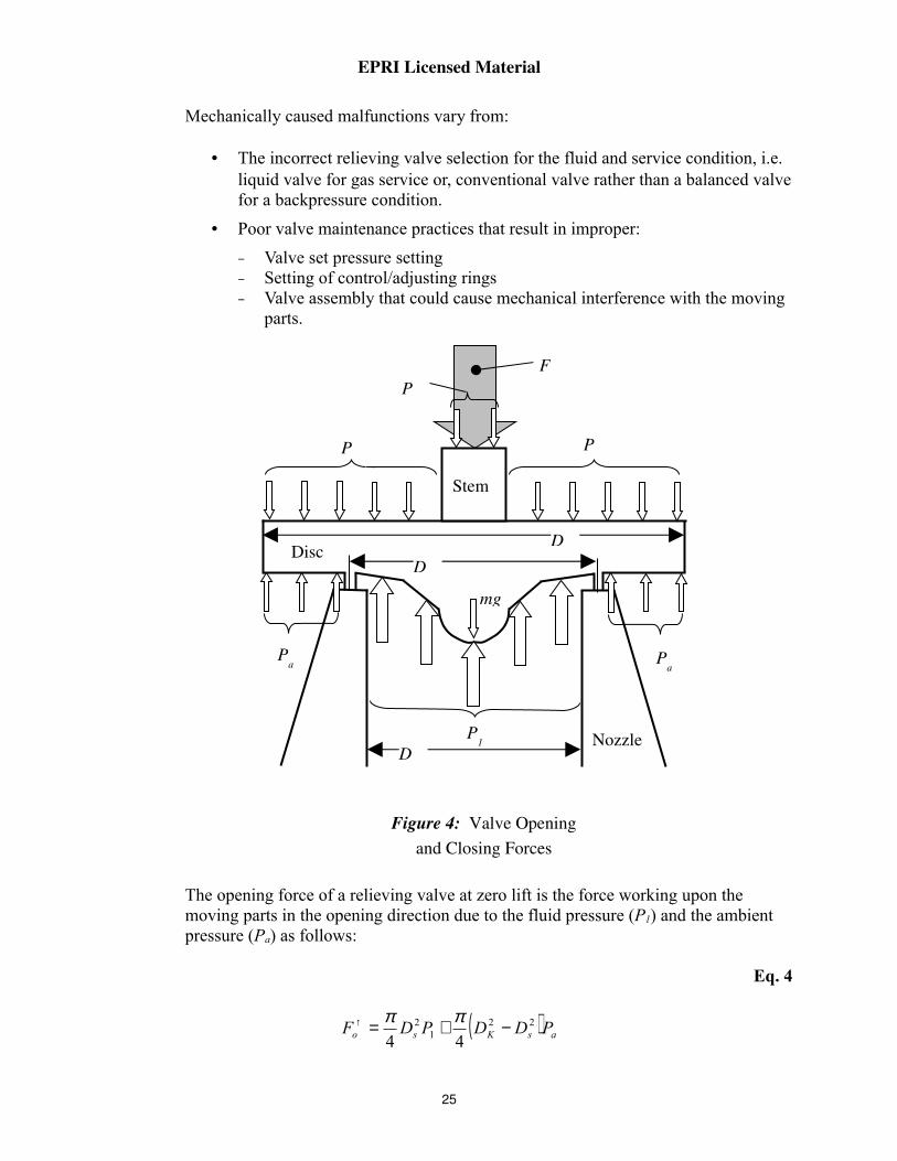
Mechanically caused malfunctions vary from:
• The incorrect relieving valve selection for the fluid and service condition, i.e. liquid valve for gas service or, conventional valve rather than a balanced valve for a backpressure condition.
• Poor valve maintenance practices that result in improper:
− Valve set pressure setting− Setting of control/adjusting rings− Valve assembly that could cause mechanical interference with the moving
parts.
The opening force of a relieving valve at zero lift is the force working upon the moving parts in the opening direction due to the fluid pressure (P1) and the ambient pressure (Pa) as follows:
Eq. 4
( ) asKso PDDPDF 221
2
44−+=↑ ππ
Stem
Disc
NozzleP1
Pa
Pa
PaP
a
Pa
Fv
mg
Dk
D
Ds
Figure 4: Valve Opening and Closing Forces
25

EPRI Licensed Material
The initial closing force of a relieving valve at zero lift is the force working upon the moving parts in the closing direction caused by the main spring force (Fv), the mass of the other moving parts (mg) and the ambient pressure (Pa), as follows:
Eq. 5
mgPDFF akvo ++=↓ 2
4
π
At zero lift the opening force equals the initial closing force, i.e. F↑o = F↓
o.
Eq. 6
( ) mgPPDF asv −−= 12
4
π
Fv is approximately equal to the force required to open the safety and relief valve.
Once the initial closing force is overcome by the increased fluid pressure in the system, the disc will lift and relieve the system pressure. The subsequent closing force can be defined as:
Eq. 7
( )( )azstemKo PPDDhkFF −−++↓= ↓ 22
4
π
The second term in the above equation is not constant since the backpressure is lift-dependent.
5.7 Relieving Valve Design Considerations
The seat of the valve is the fixed, pressure containing portion of a valve which comes in contact with the closure part, i.e. disc, of the valve. The seat can be all metal construction or may incorporate soft conforming seat inserts, such as elastomers or plastics to make a tighter seal or to reduce the required load to seat. To design a leak tight valve, there must be sufficient force between the seat and the disc to elastically or plastically deform the mating surfaces until the leak path is blocked.
In addition to the basic design of the seat itself, other factors which directly affect seating and operability are distortions that can occur at the disc/seat interface due to pressure, thermal gradients, and mechanical loads transmitted to the valve body by the adjacent piping. For
26

EPRI Licensed Material
example, applied bending forces on a valve body can cause the seat plane to tilt and distort, which can result in leakage.
To avoid leakage or binding problems caused by line loads, valves should not be located at points of large line loads. Also, the section modulus of the valve body should be significantly greater than the pipe to keep the stresses and distortions within acceptable limits.
When using metaltometal seating, the high compressive stresses required to produce surface conformance between the two seating surfaces are achieved by making narrow linetoline contact between the disc and the seat. Narrow linetoline contact should provide for a certain minimum width in order to establish a tight seal and prevent indentation type of damage caused by the plug on the seat. Additionally, the seat should have enough base width to provide adequate backup crosssection capable of supporting the high compressive stress at the discseat interface without yielding the base material.
The required degree of seat tightness and accompanying stem thrust should be reasonable selected. Specifying high seat tightness increases the size and cost of the actuator needed to develop the higher loads. An alternative to using high contact forces is the use of "superfinished" mating surfaces. However a superfinish can degrade quickly in applications where fluid contaminants are present which can get trapped between the mating surfaces during opening and closing action. Another common method used to accomplish a tight seat is to lap the disc and seat during assembly.
Developing high compressive stress to achieve good seating should be weighed against potential damage due to galling or gross surface yielding.
Cobalt60 has been identified as the principal isotope responsible for outofcore radiation contamination problems plaguing the nuclear power industry. Cobalt60 is an activation product of natural cobalt which is found in cobaltbased alloys, such as Stellite. Stellite is used mostly for hardfacing the seats and discs in valves.
Natural cobalt in these alloys is pure Cobalt59, having a thermal neutron absorption of 34 barns and, if it is in a pathway to the reactor vessel, will pass through the core, be exposed to thermal neutron flux, and be activated to Cobalt60, having a halflife of 5.25 years and emitting 1.3 mev gamma rays. These small particles accumulate in the piping system in crevices and cracks where the flow velocity is small and in stagnant pockets or "crud traps" which are inherent in the design of some valve bodies. The strength of these radioactive sources thus grows with time and becomes a major hindrance to access for maintenance work.
27
EPRI Licensed Material
Recently, there have been efforts to develop lowcobalt or cobaltfree alloys to replace cobaltbase alloys to reduce the exposure of service personnel to radiation due to Cobalt60. Several EPRIsponsored efforts have been conducted to evaluate the release of cobalt from PWR valves and from valve repair.
28
EPRI Licensed Material
5.8 Valve/System Interactions
Various interactions between the valve and the system may have an effect on the pressure boundary of the valve. These types of interactions include pipeline end load, system leakage, and piping vibration.
5.8.1 Pipeline End Loads
Since valves in major industrial piping, and in fossil and nuclear power plant piping, are usually installed using welded ends, and sometimes flanged ends, in lower pressure systems, these connections must be designed to adequately transmit all piping loads while maintaining pressure integrity. The appropriate industrial or ASME codes have the requirements to satisfy these conditions, however, the effect of piping loads must also be considered on the operability of the valve itself.
The adequacy of the pressure boundary integrity of the valve and nozzles is normally assured by verifying that the section modulus of the valve, in the approximate area of the intersection of the body and bonnet, is greater than the section modulus of the piping. The Code requires that, as a minimum, the modulus of the valve be at least 10 percent greater than that of the piping. In general practice, the modulus of the valve should be significantly greater than that of the piping, in order to assure operability of the valve. Thus, the piping which is analyzed for loading adequacy will be assumed to fail first.
For a nuclear safetyrelated active valve, a specific test is normally done on a prototype valve by imposing loading on the valve, including internal pressure loads and nozzle loads (either directly or indirectly), and operating the valve.
5.8.2 Leakage
System leakage should always be evaluated in consideration of whether the fluid is hazardous or corrosive. Flammable fluid leaks could pose a fire hazard. Boric acid leaks are of particular concern in a PWR plant because of the rapidity with which boric acid can corrode carbon steel over which it may trickle from a stem leak of a stainless steel valve. All reactor water in a PWR plant contains boric acid. Leakage which collects or dribbles on a warm surface will become concentrated as the water evaporates. Concentration may increase to the point at which the boric acid precipitates as crystals on the warm surface. Corrosion will continue underneath the crystals so long as moisture, even in the form of high humidity, is present.
29

EPRI Licensed Material
Leakage or radioactive fluids always presents a hazard which must be considered. If the fluid is highly radioactive, packless valves are generally used.
30

EPRI Licensed Material
5.8.3 Vibration
It is prudent to consider that all valves in the plant will be subject to vibration. Vibration may be transmitted to the valve through piping connected to rotating equipment, or it may result from hydrodynamic causes in the valve itself or in adjacent piping. By itself, vibration of such small amplitudes is not a problem requiring correction, but it could cause loosening of attachments and often complete separation.
Screwed connections of any kind require positive locking to prevent unscrewing or complete separation of the mating pieces. A positive locking device is one which does not depend for its functioning on friction in any way. Thus, a split washer is not a positive locking device; a castellated nut with a split pin is a positive locking device. Taper pins are not positive locking devices. Small beads of weld metal intended to secure a pin can crack from vibration or thermal cycling. Upset threads depend on friction. Many examples exist of such failures leading to valve damage or worse. This is especially the case when the loose fastener is not observable because the valve is inaccessible or the fastener is inside the valve body, or inside the housing of a valve operator. Vibration considerations must also include checking that the vibration frequency does not match the resonant frequency of the piping.
5.9 Pressure Relieving Valve Testing Requirements
The requirements for nuclear safety and relief valve performance are listed in the ASME B&PV Code Section III Article NB-7000 for Class 1 valves, NC-7000 for Class II, and ND-7000 for Class III valves. Requirements are set forth for valve set pressures, blowdown, and overpressure capacity. The summary below is based on the 1994 ASME Code Winter Addenda issued February 1995. It is important that the Code and Addenda to which the valve was manufactured, as shown on the valve nameplate and Code data report, be used for performance requirements.
Set Pressure(Note 1)
0 – 70 psi 71 – 300 psi 301 – 1000 psi Over 1000 psi
Manufacturer’sTolerance Set Pressure
±2 psi ±3% ±10 psi ±1%
Blowdown Max.(Note 1)
95%
Overpressure for Rated Capacity
Rated Capacity (Nameplate) is at 3% or 2 psi above set pressure whichever is greater
31

EPRI Licensed Material
Table 1: CLASS I SAFETY VALVE PERFORMANCE TOLERANCES(ASME Section III, Article NB-7000)
Note1: A greater set pressure tolerance and blowdown is permitted but must be specified in the valve design specification.
Gagging refers the installation of a threaded rod or similar device into the bonnet of a pressure relieving valve in order to manually hold the valve closed. This holds the spindle down and prevents the valve from opening. Valves are gagged when:
• Adjusting blowdown with the valve installed in an operating system
• Hydrostatically testing a system above the relieving valve's set pressure
• During other special testing procedures.
Valves are normally gagged by:
• Inserting a threaded screw through the bonnet of the valve, or
• By installing a clamping device that resembles a pushpuller on openbonnet valves.
CAUTION: Valve gags must be removed after adjustment or testing. Failure to do so will leave the valve inoperable and remove all overpressure protection for the system or component that is provided by the valve. Operating experience has shown that relieving valve gags have been left in place after testing and adjustment. One such case resulted in the rupture of a tank in a confined space where replacement was difficult.
5.9.1 Test Frequencies
The requirements for testing frequencies and types are set forth in the ASME B&PV Code Section XI Subsection IWV3510, ASME/ANSI Operation and Maintenance of Nuclear Power Plants Part 1 (OM1), and the ANSI/ASME Performance Test Codes (PTC) 25.3. Prior to the winter 1985 Addenda of Section XI IWV3510, Section XI required that all safety and relief valves be tested according to the Performance Test Code 25.3.
Although PTC25.3 (1988) is a Code for certification of pressure relieving valves, it does provide some guidelines, definitions, and requirements for calibration of instruments,
32

EPRI Licensed Material
training of test personnel, etc., PTC25.3 also has procedures for carrying out several types of tests on different process fluids, and there are sections devoted to capacity calculations for various test fluids.
The winter 1985 Addenda of Section XI of the ASME Code requires that safety and relief valves be tested to ANSI/ASME OM1. The 1994 edition of the ASME OM1 Code, Appendix I, a mandatory appendix, is the result of years of Code work for inservice testing of pressure relieving valves in light water reactor power plants.
The general requirements sections of OM1, Appendix I defines the scope, terminology, and the responsibilities of plant personnel. Also included are the requirements for testing frequency which requires all Class 1 valves of each type and manufacturer to be tested at least once every five years. All Class 2 valves are to be tested once every ten years.
OM1, Appendix I provides explicit instructions as to the types of testing required for asfound and asleft conditions and the sequence in which the testing shall be accomplished. The test scope for an individual valve depends on its ASME component class, its function in the plant and design of the valve.
5.9.2 Test Parameters
There are four basic parameter associated with safety valve operation that must be tested. These are set pressure, blowdown, capacity, and seat tightness or leakage. However, inservice testing of pressure relieving valves according to OM1, Appendix I, does not require blowdown or capacity testing.
5.9.2.1 Set Pressure
The set pressure of a pressure relieving valve on a steam or a compressible fluid is the pressure at which the valve will “pop”. This parameter is directly affected by the amount of compressive force exerted on the valve seat by the valve spring. The control for how much force the spring exerts is accomplished by raising or lowering the adjusting bolt or compression screw.
There are several acceptable methods for testing for relieving valve set pressure. The test media for set pressure testing will vary with the valve service. For steam valves, saturated steam or other compressible fluid with correlating data shall be used. For valves on a compressible fluid other than steam, air or nitrogen shall be used. For liquid service valves, liquid shall be used. The accumulator used shall have a volume
33

EPRI Licensed Material
and pressure source sufficient to determine the valve set pressure. The valve lift may be restricted if a free falling disc at full lift would damage the valve. An assist device is allowable for set pressure testing of compressible fluid valves only.
A requirement for set pressure testing is that the temperature of the valve body must be stabilized and known prior to testing. Additionally, the ambient temperature of the operating environment shall be simulated during testing, or a correlation factor used. The Code allows the control rings to be adjusted to ensure valve action. However, when testing for set pressure, the control rings cannot be altered between openings. Consideration for superimposed backpressure must be known and compensated for in valve set pressure (if required). Currently the minimum elapsed time between set pressure openings is 10 minutes. However, the ASME OM1 Code Committee is looking into reducing this time interval to 5 minutes.
34

EPRI Licensed Material
For asfound set pressure testing the owner shall specify the acceptance criteria. For asleft set pressure testing a minimum of two consecutive openings within the ownerspecified tolerance is required to demonstrate valve compliance. For compressible fluid applications, set pressure opening is defined by the “pop” of the valve. For liquid service, the set pressure can be a pencil stream, excessive flow, or even a twostep flow change.
The set point tolerance is a requirement that specifies the pressure range the valve should provide over and under pressure protection. Each plant’s specific asfound requirements may be different than the Code requirements due to design conditions. However, for the asleft requirements, the acceptance criteria should always comply with the Code. The tolerances used in the set pressure testing of pressure relieving valves in accordance with the OM Code, Appendix I are determined from the individual plant’s technical specifications and the valve’s design specification that may require compliance with Section III of the ASME Code or some other greater value.
OM1, Appendix I allows the utility to make simple set pressure adjustments if a valve fails the set pressure acceptance criteria by less than +3% of its stamped setpoint. For any valve that exceeds its stamped setpoint by more than +3%, a root cause determination must be made and the valve must be repaired or replaced.
OM-1, Appendix I allows the utility to evaluate the need for additional tests if the valve does not meet set pressure test criteria.
For each valve tested for which the as-found set pressure (first actuation) exceeds the greater of either the ± tolerance limit of the owner’s established set pressure acceptance criteria or ±3% of the valve nameplate set pressure (not necessarily the conservative value):
• Two additional valves shall be tested of the same valve group
• If the asfound set pressure of any of the additional valves tested in accordance with the paragraph above exceeds the criteria noted therein, then all the remaining valves in the same valve group shall be tested.
5.9.2.2 Blowdown
The blowdown of a valve is described as the difference between the valve’s actual “popping” pressure and actual reseating pressure. The ASME Code places
35
EPRI Licensed Material
requirements on the amount of blowdown, i.e., the value below the “popping” pressure the reseating pressure can be, that a newly manufactured valve must have. For Section III Class I, nuclear power plants, it is generally required that the blowdown be specified in the valve design specification and the basis for it to be covered in the overpressure protection report.
In order to properly test for blowdown, the test facility must have adequate fluid flow to cause the valve to achieve a substantial lift and then to close. Capacity testing, achieving full lift on large valves like pressurizer or main steam safety valves can be difficult. Lift assist devices cannot be used when testing for blowdown since the valve does not achieve full lift.
5.9.2.3 Capacity
Capacity refers to the amount of fluid a valve can pass at a given overpressure in a given time. Capacity is usually measured in gallons per minute (gpm) for water valves, pounds of steam per hour (lb/hr) for steam service, and standard cubic feet/minute (SCFM) for air. There is no Code requirement for a plant to conduct a capacity test for valves that have an ASME Code symbol stamp.
5.9.2.4 Seat Tightness Testing
The ASME Code, with the advent of ASME/ANSI OM-1, Appendix I has established leakage limits for safety valves and require utilities to test their pressure relieving valves for seat tightness. Seat tightness requirements for newly manufactured pressure relieving valves are usually specified on the valve design specification. Typically, API Standard 527, “Seat Tightness Pressure Relief Valves”, may be referenced. There are several methods mentioned in ASME OM-1, Appendix I that may be employed to establish whether or not a valve is leaking. The OM-1 Code requires leak tests be performed on the valves at either maximum system operating pressure or as specified by the owner.
There are several methods that may be used to test for valve leakage on steam. When in service test are performed, these methods are either qualitative or quantitative.
• Audible/Visible Test
• Downstream Temperature Measurement Test
• Weighed Condensate Test
• Cold Bar Test
• Acoustic Emission Test
• Flow Rate Test
36

EPRI Licensed Material
Seat tightness testing must be performed prior to as-found testing and after the final as-left set pressure test. However, the type of seat tightness test performed is left to the utility to decide depending upon the valve type and service conditions. The type of test performed should be based on the importance of the individual valve to the system and type of fluid medium such as steam, air or nitrogen that it services.
37

EPRI Licensed Material
5.9.2.5 Bellows Testing
OM-1, Appendix I requires that the integrity of a bellows in a balance valve be tested, but it does not specifically outline how this test should be performed. Normally, bellows testing is carried out in the following manner:
• A blank flange or pipe cap is installed on the outlet of the valve
• Gas pressure is then applied to the outlet of the valve through a pressure connection welded to the blank flange or pipe cap
• The bonnet vent should be used to sense bellows leakage with soap bubble or bubble counter.
38

EPRI Licensed Material
39

EPRI Licensed Material
6.0 NUCLEAR CONSIDERATIONS
For active nuclear safetyrelated valve assemblies, qualification by analysis and/or test is required to assure that the valves will operate on demand under all conditions, including seismic loads, other dynamic loads, and adverse environmental conditions, both external and internal.
The qualification requirements are delineated in documents such as 10CFR50, U.S. NRC Regulatory Guides, and Standard Review Plans. Several industry standards have been issued to address qualifications, such as:
• IEEE382, "Qualification of Actuators for Power Operated Valve Assemblies with Safety Related Functions in Nuclear Power Plants"
• IEEE323, "Qualifying Class IE Equipment for Nuclear Power Generating Stations"
• IEEE344, "Recommended Practices for Seismic Qualification of Class IE Equipment for Nuclear Power Generating Stations"
• ANSI B16.41, "Functional Qualification Requirements for Power Operated Active Valve Assemblies for Nuclear Power Plants".
40

EPRI Licensed Material
41
EPRI Licensed Material
7.0 UTILITY EXAMPLE EXERCISES AND SOLUTIONS
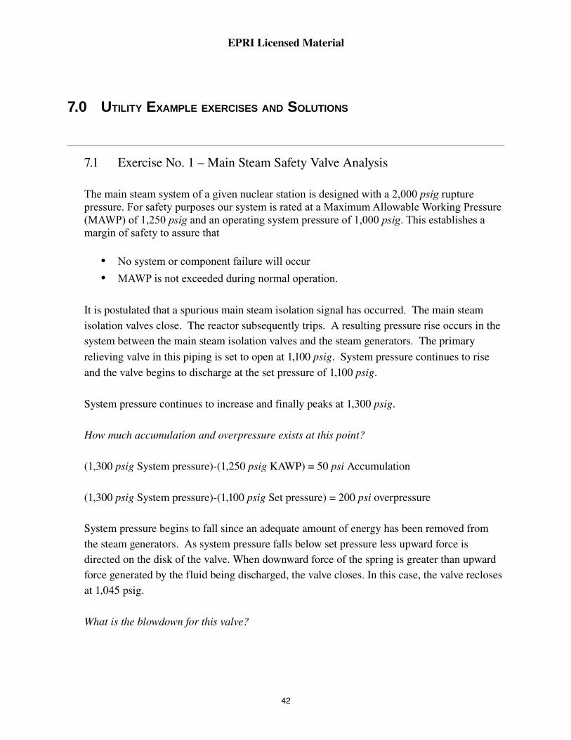
7.1 Exercise No. 1 – Main Steam Safety Valve Analysis
The main steam system of a given nuclear station is designed with a 2,000 psig rupture pressure. For safety purposes our system is rated at a Maximum Allowable Working Pressure (MAWP) of 1,250 psig and an operating system pressure of 1,000 psig. This establishes a margin of safety to assure that
• No system or component failure will occur
• MAWP is not exceeded during normal operation.
It is postulated that a spurious main steam isolation signal has occurred. The main steam isolation valves close. The reactor subsequently trips. A resulting pressure rise occurs in the system between the main steam isolation valves and the steam generators. The primary relieving valve in this piping is set to open at 1,100 psig. System pressure continues to rise and the valve begins to discharge at the set pressure of 1,100 psig.
System pressure continues to increase and finally peaks at 1,300 psig.
How much accumulation and overpressure exists at this point?
(1,300 psig System pressure)(1,250 psig KAWP) = 50 psi Accumulation
(1,300 psig System pressure)(1,100 psig Set pressure) = 200 psi overpressure
System pressure begins to fall since an adequate amount of energy has been removed from the steam generators. As system pressure falls below set pressure less upward force is directed on the disk of the valve. When downward force of the spring is greater than upward force generated by the fluid being discharged, the valve closes. In this case, the valve recloses at 1,045 psig.
What is the blowdown for this valve?
42

EPRI Licensed Material
The difference between set pressure and reclosing pressure of the valve. Since it is commonly expressed in a percentage, the following method is used to determine the "percentage" of blowdown.
(1,100 psig Set pressure) – (1,045 psig Reclosing pressure) = 55 psig blowdown
55/1100 = 5% blowdown
How can blowdown for a main steam safety valve be increased?
If the valve has both upper and lower adjusting rings, altering the position of the upper ring changes the size of the huddling chamber giving a greater/lesser percentage of blowdown. If one lower adjusting ring is used, repositioning it adjusts the nozzling effect on the fluid. The amount of fluid focused on the disc assembly and the length of time the fluid is held in the nozzle and disk area is affected. This increases or reduces the amount of upward force and results in a greater or lesser percentage of blowdown.
NOTE:Although the valve will currently reclose at a pressure somewhat higher than operating pressure system operation can be adjusted to further reduce system pressure.
43

EPRI Licensed Material
44
EPRI Licensed Material
8.0 SOURCE DOCUMENTATION
1. Safety and Relief Valve Testing and Maintenance Guide, EPRI TR105872, August 1996.
2. Guide for the Application and Use of Valves in Power Plant Systems, EPRI NP6516, August 1990.
3. Safety and Relief Valves in Light Water Reactors, EPRI NP4306SR, December 1985.
45

EPRI Licensed Material
46

EPRI Licensed Material
9.0 INDUSTRY OPERATING EXPERIENCE
• SOERs
SOER 816 Dresser Safety Valve Blowdown Setting
SOER 818 Spurious Actuation of Safety/Relief Valve
SOER 829 Ring Settings for Dresser Safety Valves
SOER 8281 Brazed Spring Guides in Dresser Relief Valves
SOER 8383 Stress Corrosion Cracking for Pilot Line for Pressurizer Safety Valve
SOER 8484 Loss of Reactor Coolant Due to Stuck Open Relief Valve and Blocked Valve
• NRC Bulletins or Generic Letters
GL8136 Revised Schedule for Completion of TMI Action Plan Item II.D.I Relief and Safety Valves in PWRs
BL7404 Malfunction of Target Rock Safety Relief Valves
BL7414 BWR Relief Valve Discharge to Suppression Pool
BL8025 Operating Problems with Target Rock Relief Valves at BWRs
AEOD/S9202 Special StudySafety and Safety/Relief Valve Reliability
NUREG1482 Guidelines for InService Testing in Nuclear Power Plants
47

EPRI Licensed Material
48

EPRI Licensed Material
10.0 PROFICIENCY MEASURES
10.1 Proficiency Measures (Questions):
1. Name four types of pressure relieving valves.
2. What are the primary service conditions that each pressure relieving valve type is used for?
3. What is the difference between a "balanced" and an "unbalanced" safety and relief valve?
4. Define "blowdown" as it relates to a pressure relieving valve.
5. Name four different methods for testing for seat tightness in a pressure relieving valve.
6. Are ASME pressure relieving valves required to be periodically capacity tested?
7. Is seat leakage permissible from safety valves installed to protect main steam piping in a PWR?
8. Why does a safety valve open so much more quickly than a relief valve?
49
EPRI Licensed Material
10.2 Proficiency Measures (Solutions)
1. Relief valve, safety valve, safety and relief valve, and poweroperated relief valve (PORV)
2. The four pressure relieving valves and the associated primary service are:
• Relief Valve – Liquid Service• Safety Valve – Gas or Steam Service• SafetyRelief Valve – Steam Service (can also be used on liquid service)• PORV – Steam Service
3. In a "balanced" safety and relief valve, the uncompensated area of the disc is isolated from the system backpressure by means of a bellows, which is vented to the atmosphere. In the "unbalanced" valve, the system backpressure affects the set pressure of the valve.
4. Blowdown is the difference between the safety valve's actual “popping” pressure and the actual reseating pressure. It is usually expressed as a percent of the “popping” pressure.
5. Downstream Temperature Measurement Test, Weighed Condensate Test,Cold Bar Test, Acoustic Emission Test, Flow Rate Test, Audible/Visible Test
6. There is no Code requirement for a plant to conduct a capacity test for valves that have an ASME Code symbol stamp.
7. Leak requirements are established by code but the method is set by the utilities. Consideration must be given, however, to dose consequences of allowable primary to secondary leakage. The offsite dose calculations may assume less leakage than allowed by the code.
8. Because of the additional surface area that is “seen” by the discharged fluid once the disk has just lifted off its seat. This significantly increases the force acting upon the disk and results in quick action. The surface area acted upon by relief valve liquids remains constant so the disk displacement is progressive.
50

EPRI Licensed Material
51


The Electric Power Research Institute (EPRI)The Electric Power Research Institute (EPRI), with major locations in Palo Alto, California, and Charlotte, North Carolina, was established in 1973 as an independent, nonprofit center for public interest energy and environmental research. EPRI brings together member organizations, the Institute’s scientists and engineers, and other leading experts to work collaboratively on solutions to the challenges of electric power. These solutions span nearly every area of power generation, delivery, and use, including health, safety, and environment. EPRI’s members represent over 90% of the electricity generated in the United States. International participation represents over 10% of EPRI’s total R&D program.
Together . . . Shaping the Future of Electricity
Export Control Restrictions
Access to and use of EPRI Intellectual Property is granted with the specific understanding and requirement that responsibility for ensuring full compliance with all applicable U.S. and foreign export laws and regulations is being undertaken by you and your company. This includes an obligation to ensure that any individual receiving access hereunder who is not a U.S. citizen or permanent U.S. resident is permitted access under applicable U.S. and foreign export laws and regulations. In the event you are uncertain whether you or your company may lawfully obtain access to this EPRI Intellectual Property, you acknowledge that it is your obligation to consult with your company’s legal counsel to determine whether this access is lawful. Although EPRI may make available on a case by case basis an informal assessment of the applicable U.S. export classification for specific EPRI Intellectual Property, you and your company acknowledge that this assessment is solely for
SINGLE USER LICENSE AGREEMENTTHIS IS A LEGALLY BINDING AGREEMENT BETWEEN YOU AND THE ELECTRIC POWER RESEARCH INSTITUTE, INC. (EPRI). PLEASE READ IT CAREFULLY REMOVING THE WRAPPING MATERIAL.
BY OPENING THIS SEALED PACKAGE YOU ARE AGREEING TO THE TERMS OF THIS AGREEMENT. IF YOU DO NOT AGREE TO THE TERMS OF THIS AGREEMENT, PROMPTLY RETURN THE UNOPENED PACKAGE TO EPRI AND THE PURCHASE PRICE WILL BE REFUNDED.
1. GRANT OF LICENSE
EPRI grants you the nonexclusive and nontransferable right during the term of this agreement to use this package only for your own benefit and the benefit of your organization. This means that the following may use this package: (I) your company (at any site owned or operated by your company); (II) its subsidiaries or other related entities; and (III) a consultant to your company or related entities, if the consultant has entered into a contract agreeing not to disclose the package outside of its organization or to use the package for its own benefit or the benefit of any party other than your company.
This shrinkwrap license agreement is subordinate to the terms of the Master Utility License Agreement between most U.S. EPRI member utilities and EPRI. Any EPRI member utility that does not have a Master Utility License Agreement may get one on request.
2. COPYRIGHT
This package, including the information contained in it, is either licensed to EPRI or owned by EPRI and is protected by United States and international copyright laws. You may not, without the prior written permission of EPRI, reproduce, translate or modify this package, in any form, in whole or in part, or prepare any derivative work based on this package.
3. RESTRICTIONS
You may not rent, lease, license, disclose or give this package to any person or organization, or use the information contained in this package, for the benefit of any third party or for any purpose other than as specified above unless such use is with the prior written permission of EPRI. You agree to take all reasonable steps to prevent unauthorized disclosure or use of this package. Except as specified above, this agreement does not grant you any right to patents, copyrights, trade secrets, trade names, trademarks or any other intellectual property, rights or licenses in respect of this package.
4. TERM AND TERMINATION
This license and this agreement are effective until terminated. You may terminate them at any time by destroying this package. EPRI has the right to terminate the license and this agreement immediately if you fail to comply with any term or condition of this agreement. Upon any termination you may destroy this package, but all obligations of nondisclosure will remain in effect.
5. DISCLAIMER OF WARRANTIES AND LIMITATION OF LIABILITIES
NEITHER EPRI, ANY MEMBER OF EPRI, ANY COSPONSOR, NOR ANY PERSON OR ORGANIZATION ACTING ON BEHALF OF ANY OF THEM:
(A) MAKES ANY WARRANTY OR REPRESENTATION WHATSOEVER, EXPRESS OR IMPLIED, (I) WITH RESPECT TO THE USE OF ANY INFORMATION, APPARATUS, METHOD, PROCESS OR SIMILAR ITEM DISCLOSED IN THIS PACKAGE, INCLUDING MERCHANTABILITY AND FITNESS FOR A PARTICULAR PURPOSE, OR (II) THAT SUCH USE DOES NOT INFRINGE ON OR INTERFERE WITH PRIVATELY OWNED RIGHTS, INCLUDING ANY PARTY’S INTELLECTUAL PROPERTY, OR (III) THAT THIS PACKAGE IS SUITABLE TO ANY PARTICULAR USER’S CIRCUMSTANCE; OR
B) ASSUMES RESPONSIBILITY FOR ANY DAMAGES OR OTHER LIABILITY WHATSOEVER (INCLUDING ANY CONSEQUENTIAL DAMAGES, EVEN IF EPRI OR ANY EPRI REPRESENTATIVE HAS BEEN ADVISED OF THE POSSIBILITY OF SUCH DAMAGES) RESULTING FROM YOUR SELECTION OR USE OF THIS PACKAGE OR ANY INFORMATION, APPARATUS, METHOD, PROCESS OR SIMILAR ITEM DISCLOSED IN THIS PACKAGE.
6. EXPORT
The laws and regulations of the United States restrict the export and reexport of any portion of this package, and you agree not to export or reexport this package or any related technical data in any form without the appropriate United States and foreign government approvals.
7. CHOICE OF LAW
This agreement will be governed by the laws of the State of California as applied to transactions taking place

Electric Power Research Institute • 3412 Hillview Avenue, Palo Alto, California 94304 • PO Box 10412, Palo Alto, California 94303 • USA800.313.3774 • 650.855.2121 • [email protected] • www.epri.com