engineering standard for process design of solids
TRANSCRIPT

IPS-E-PR-380
This Standard is the property of Iranian Ministry of Petroleum. All rights are reserved to the owner. Neither whole nor any part of this document may be disclosed to any third party, reproduced, stored in any retrieval system or transmitted in any form or by any means without the prior written consent of the Iranian Ministry of Petroleum.
ENGINEERING STANDARD
FOR
PROCESS DESIGN OF SOLIDS HANDLING SYSTEMS
ORIGINAL EDITION
DEC. 1997
This standard specification is reviewed and updated by the relevant technical committee on Aug. 2004. The approved modifications are included in the present issue of IPS.

Dec. 1997
IPS-E-PR-380
1
CONTENTS : PAGE No. 0. INTRODUCTIONS........................................................................................................................... 2 1. SCOPE ............................................................................................................................................ 3 2. REFERENCES ................................................................................................................................ 3 3. SYMBOLS AND ABBREVIATIONS ............................................................................................... 4 4. UNITS .............................................................................................................................................. 4 5. GENERAL CONSIDERATIONS ..................................................................................................... 4
5.1 Most Salient Features ............................................................................................................. 4 5.2 Fluidization Characteristics ................................................................................................... 5 5.3 Flow Function.......................................................................................................................... 5 5.4 Important Flow Features ........................................................................................................ 6
5.4.1 Factors influencing flow ................................................................................................. 6 6. CONVEYING OF BULK SOLIDS ................................................................................................... 6
6.1 Conveyor Selection................................................................................................................. 6 6.2 Mechanical Conveyors ........................................................................................................... 7
6.2.1 General.............................................................................................................................. 7 6.2.2 Selection of mechanical conveyors............................................................................... 7 6.2.3 Belt conveyors ................................................................................................................. 9 6.2.4 Screw conveyors ........................................................................................................... 11
6.3 Continuous–– Handling Equipment or Pneumatic Conveyors ........................................ 13 6.3.1 General............................................................................................................................ 13 6.3.2 Advantages and disadvantages of pneumatic conveyors ........................................ 13 6.3.3 Types of pneumatic conveying systems..................................................................... 14 6.3.4 Effects of material properties ....................................................................................... 17 6.3.5 Design considerations .................................................................................................. 18
7. HANDLING BULK MATERIALS IN PACKAGES AND CONTAINERS ...................................... 19 7.1 Main Factors ...................................................................................................................................... 19
7.2 Selection of Container .......................................................................................................... 20 7.2.2 Paper bag........................................................................................................................ 20 7.2.3 Fiber drums .................................................................................................................... 20 7.2.4 Steel drums .................................................................................................................... 21
8. STORAGE OF SOLIDS IN BULK................................................................................................. 21 8.1 Outdoor Bulk Storage (Pile) ................................................................................................. 21
8.1.1 General............................................................................................................................ 21 8.1.2 Designing and outdoor storage bin ............................................................................. 21

Dec. 1997
IPS-E-PR-380
2
0. INTRODUCTIONS
Handling of solids play an important role in the vast number of industries, particularly in chemicals and petrochemical process industries. Bulk materials handling comprises a wide range of techniques incorporating a number of handling modes. Attempts are made here to highlight some of the important modes specifically utilized in OGP process plants by providing basis on which the basic conveying requirements, and parameters are given for proper selection, design of the systems.
"Process Design of Offsite Facilities for OGP Processes", are broad and contain various subjects of paramount importance. Therefore, a group of Process Engineering Standards are prepared to cover this subject. This group includes the following Standards:
STANDARD CODE STANDARD TITLE
IPS-E-PR-360 "Process Design of Liquid and Gas Transfer and Storage"
IPS-E-PR-370 "Process Design of Loading & Unloading Facilities"
IPS-E-PR-380 "Process Design of Solids Handling Systems"
This Engineering Standard Specification covers:
"PROCESS DESIGN OF SOLIDS HANDLING SYSTEMS"

Dec. 1997
IPS-E-PR-380
3
1. SCOPE
This Engineering Standard Specification is intended to cover basic minimum process requirements, and governing the selection of a proper handling system for bulk materials, with specific concern to capacity requirements, material characteristics, process requirements, and flow properties of solids. Classification codes summarizing bulk solids behavior, process design considerations from the views of operating conditions and other process design information and criteria to the extent specified herein are covered.
Note: This standard specification is reviewed and updated by the relevant technical committee on Aug. 2004. The approved modifications by T.C. were sent to IPS users as amendment No. 1 by circular No. 240 on Aug. 2004. These modifications are included in the present issue of IPS.
2. REFERENCES
Throughout this Standard the following dated and undated standards/codes are referred to. These referenced documents shall, to the extent specified herein, form a part of this standard. For dated references, the edition cited applies. The applicability of changes in dated references that occur after the cited date shall be mutually agreed upon by the Company and the Vendor. For undated references, the latest edition of the referenced documents (including any supplements and amendments) applies.
BSI (BRITISH STANDARDS INSTITUTION)
BS 4409, Part 1, 1991 "Screw Conveyors, Specification for Fixed Trough Type"
BS 4409, Part 3, 1982 "Screw Conveyors, Method for Calculating Driver Power"
ISO (INTERNATIONAL ORGANIZATION FOR STANDARDIZATION)
ISO 7119, 1st. Ed., 1981 "Continuous Mechanical Handling Equipment for Loose Bulk Materials Screw Conveyors"
ISO 5048, 2nd. Ed.,1989 "Continuous Mechanical Handling Equipment Belt Conveyors with Carrying Idlers-Calculation of Operating Power and Tensile Forces"
ISO 2148, 1st. Ed., 1974 "Continuous Handling Equipment Nomenclatures"
ANSI/CEMA (AMERICAN NATIONAL STANDARD INSTITUTE/CONVEYOR EQUIPMENT MANUFACTURERS ASSOCIATION)
350 Class III E, 1st Ed., 1971 "Screw Conveyors"
350 Class IV E, 1st. Ed., 1970 "Package Handling Conveyors"
IPS (IRANIAN PETROLEUM STANDARDS)
IPS-E-GN-100 “Engineering Standard for Units”
IPS-M-GN-210 "Material and Equipment Standard for Conveyors"
IATA (INTERNATIONAL AIR TRANSPORTATION ASSOCIATION)
Dec. 1997
IPS-E-PR-380
4
CAB (CIVIL AERONAUTICS BOARD)
3. SYMBOLS AND ABBREVIATIONS
CAB Civil Aeronautics Board.
CEMA Conveyor Equipment Manufacturers Association.
D Nominal screw diameter, in (m).
DOT Department Of Transportation.
g Acceleration due to gravity, in (m/s²).
H Height to which the material to be elevated, in (m).
IATA International Air Transportation Association.
Iv Volume flow rate, in (m³/h).
L Length of conveyor, in (m).
OGP Oil, Gas and Petrochemical.
PH Power necessary for the progress of the material, in (kW).
PN Drive power of screw conveyor at no load condition, in (kW).
Pst Power due to inclination, in (kW).
ρ (rho) Bulk density, in (kg/m³).
φ (Phi) Trough filling coefficient, (dimensionless).
θ (theta) Cone angle, in (rad).
W Product capacity, or carrying capacity of belt, in (kg/s).
4. UNITS
This Standard is based on International System of Units (SI), except where otherwise specified IPS-E-GN-100.
5. GENERAL CONSIDERATIONS
5.1 Most Salient Features
Selection of a specific handling system for bulk materials requires a full knowledge of the physical and chemical properties of the materials to be handled. Material characteristics and the prevailing plant conditions, play an important role in determining the flow behavior of the product, thereby influencing the type of the equipment selected. The most salient features for selection of a suitable handling system are:
a) Capacity
Capacity requirement is a prime factor in conveyor selection. Belt conveyors which can be manufactured in relatively large sizes, to operate at high speeds, deliver large tonnage economically. On the other hands screw conveyors become extremely cumbersome as they get larger and can not be operated at high speeds without creating serious abrasion problems.
b) Distance
Length of travel is definitely limited for certain type of conveyers. With high-tensile-strength belting, the length limit on belt conveyors can be a matter of miles. Air conveyors are limited to
Dec. 1997
IPS-E-PR-380
5
300 meters, vibrating conveyors to 100 meters. In general as the length of travel increases, the choice among alternatives become narrower.
c) Lift
Lift usually can be handled most economically by vertical or inclined bucket elevators, but when lift and horizontal travel are combined, other conveyors should be considered. Conveyers that combine several direction of travel in single unit are generally more expensive, but since they require a single drive, this feature often compensates for the added base cost.
d) Materials
Material characteristics, both chemical and physical characteristics should be considered especially flowability, abrasiveness, friability and lump size. Effects of chemicals, moisture and oxidation effects from exposure to atmosphere can be harmful to the material being conveyed, or to the conveyor’s material. Certain type of conveyors lend themselves to such special requirements better than the others.
e) Processing
Processing requirements can be met by some conveyors with little or no change in design. For example, screw conveyors are available for a wide variety of processing operations such as mixing, dewatering, heating and cooling. A continuous flow conveyor may provide a desired cooling for solids simply because it puts the conveyed material into direct contact with heat conducting metals.
f) Flow properties of solids
The flow characteristics of bulk solid materials depend on their physical and chemical properties. The main characterizing factors to be considered in selection of solids conveying systems are:
1) Product grouping
The flowability of the product yields,two main categories of bulk solids is specified under 1.1 and 1.2 herein below:
1.1) Group I
This group includes free-flowing materials, i.e., non cohesive products; those that do not undergo any plastic deformation when subjected to high pressures. When the load is removed, the particles return to their original condition in terms of both shape, and flow characteristics.
1.2) Group II
All products which undergo plastic deformation when subjected to external pressure i.e., cohesive products for which the degree of deformation is strongly influenced by both temperature and moisture. When the load is removed, the particles do not regain their original shape, thereby yielding poor flow condition.
5.2 Fluidization Characteristics
The ability of the material to fluidize and whether the product has an affinity to trap air or gas is of major importance when designing and selecting of solids handling and storage systems.
5.3 Flow Function
Flow functions for both short and long residence time in silos and storage bins shall be taken into account in design and selection. Additional complications occur when the product is stored at

Dec. 1997
IPS-E-PR-380
6
elevated temperature or when humidity could influence the moisture content of the product.
5.4 Important Flow Features
For the successful operation of any materials handling system the flow of solids from bins and silos must be controlled. The following important features should be considered in selection and design of such storage facilities.
5.4.1 Factors influencing flow
Three essential factors must be considered when designing a storage hopper or bin:
1) Geometric form of the hopper: the elements which must be considered includes:
a) cone angle è (theta);
b) size of outlet;
c) shape (circular or rectangular);
d) hopper construction material.
2) Product characteristics:
a) particle size and shape;
b) particle size distribution;
c) particle density and bulk density;
d) cohesiveness of the product;
e) fluidizability;
f) floodability;
g) deaeration characteristics.
3) Additional factors:
a) influence of humidity;
b) temperature of product and process;
c) storage time;
d) ambient conditions.
6. CONVEYING OF BULK SOLIDS
6.1 Conveyor Selection
6.1.1 Main guidelines and prime factors are given under Clause 5 of this Specification that must be considered in the course of evaluating and selection. However, it is advisable to check with the manufacturer to be sure that the application is proper.
6.1.2 Conveyor selection must be based on the as-conveyed characteristics of a material. For instantance if packing or aerating can occur in the conveyor, the machine’s performance will not meet expectations if calculations are based on an average mass per cubic meter. Storage conditions, variations in ambient temperature and humidity, and storage methods may all affect

Dec. 1997
IPS-E-PR-380
7
conveying characteristics. So, such factors should also be carefully considered before making a final conveyor selection.
6.2 Mechanical Conveyors
6.2.1 General
6.2.1.1 Mechanical conveying techniques are the most widely used form of materials handling in chemical and petrochemical industries. Mechanical conveyors have distinct advantages in terms of the ability to effect accurate control in the monitoring of material from one process to another.
6.2.1.2 Under this Standard Specification, some basic features of the various types of mechanical conveyors as well as the safety and environmental considerations are covered.
6.2.2 Selection of mechanical conveyors
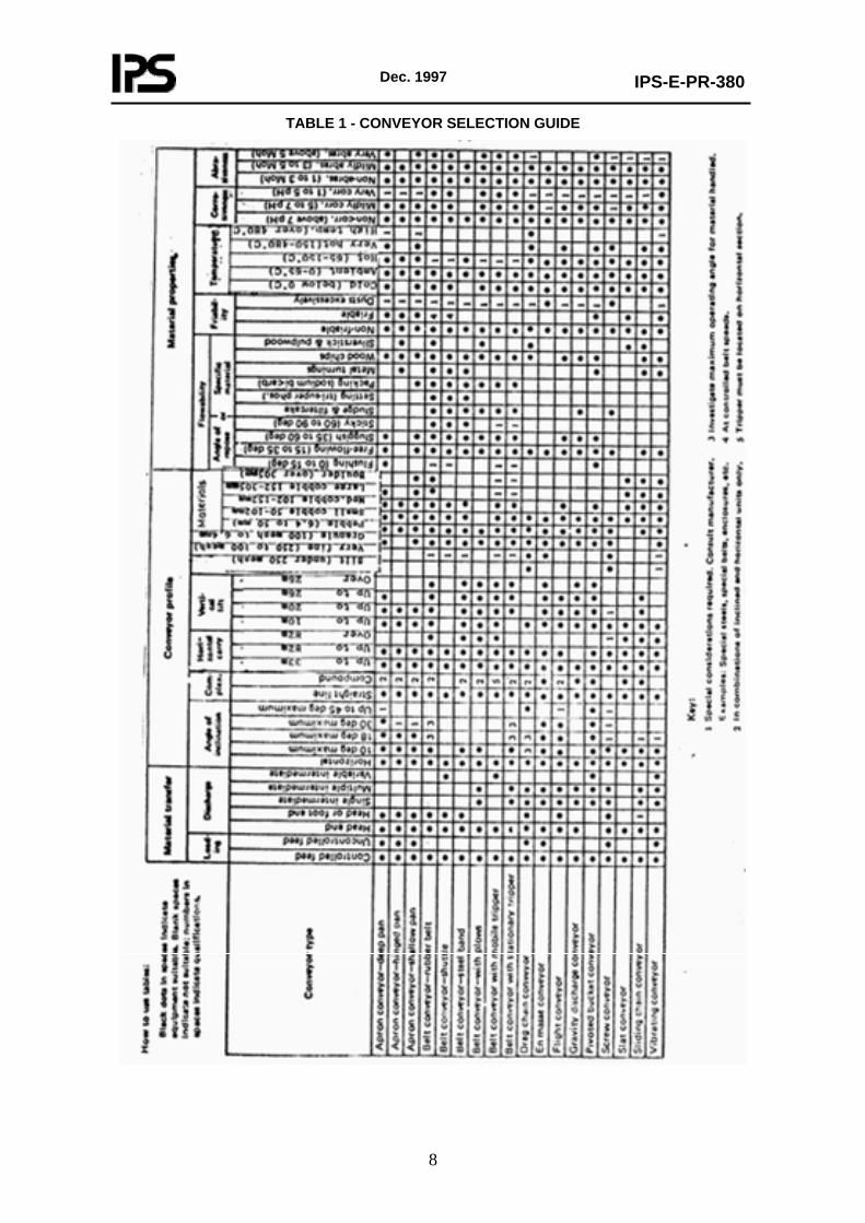
6.2.2.1 Not contrary with requirements given in Clause 5, the review to conveyor selection guide given in Table 1 is recommended to be considered.
Dec. 1997
IPS-E-PR-380
8
TABLE 1 - CONVEYOR SELECTION GUIDE

Dec. 1997
IPS-E-PR-380
9
6.2.3 Belt conveyors
6.2.3.1 General
Belt conveyors are the most widely used and versatile mode of mechanical conveying systems employed to transport materials horizontally or on an inclined either up or down. Fig. 1, represents a typical belt-conveyor arrangement, with following main components of the system:
TYPICAL BELT-CONVEYOR ARRANGEMENT
Fig. 1
a) The belt, which forms the moving and supporting surface on which the conveyed material rides.
b) The idler, which form the supports for the carrying and return strands of the belt.
c) The pulleys, which support and move the belt and control its tension.
d) The drive, which imparts power to one or more pulleys to move the belt and it’s load.
e) The structure, which supports and maintains the alignment of the idlers and pulleys, and supports the driving machineries.
6.2.3.2 Requirements
6.2.3.2.1 Unless otherwise specified, all conveyers, drives, supports, electricals including control panel and other materials necessary to complete the conveying system shall be furnished by the Vendor.
6.2.3.2.2 Vendor shall furnish all appliances, special tools, and accessories that are necessary or incidental to the proper installation and safe operation of the equipment, even though these items may not be included in the drawings, specifications, or data sheets.
6.2.3.2.3 A summary of utility requirements including electric power, plant and instrument air, cooling water, steam, etc., shall be submitted with the Vendor’s quotation.
6.2.3.2.4 Vendor shall submit recommendations for following 3 categories of spare parts:
a) Erection and pre-commissioning.
b) Commissioning and initial operation.

Dec. 1997
IPS-E-PR-380
10
c) 2 years of normal operation.
6.2.3.3 Design
6.2.3.3.1 Conveying system shall be designed for 24 hours, continuous operation at the rated output in the specified environment.
6.2.3.3.2 General arrangement drawings of conveying system showing location of gravity take-up, bents, support locations, etc., which shall be prepared by the Vendor.
6.2.3.3.3 Vendor shall be responsible to guarantee performance of the belt conveyor system. The data sheets, and drawings shall indicate minimum requirements, but these shall in no way relieve the Vendor from his responsibility for providing a system capable to meet the required performance.
6.2.3.3.4 Materials of construction shall be selected and specified in accordance with service condition and handling material specification see IPS-M-GN-210.
6.2.3.3.5 Belt conveyors shall be CEMA Grade 2, designed for the material conveying temperature.
6.2.3.3.6 The following operating conditions shall be considered in belt conveyor design:
a) Service condition, is the first step which should be considered. The method by which the conveyor will be fed, the point where loading will takes place, and where the material will be discharged.
b) Surroundings, which involve such conditions as high temperature or corrosive atmosphere can affect the belt, machinery and structure.
c) Continuous service, may require extremely high quality components and even specially designed equipment for servicing while the belt is in operation.
d) Belt width and operating speed, are functions of the bulk density and lump size of the material, using the narrowest possible belt for a given lump size and operating it at maximum speed can result in lowest cost.
e) For detailed design requirement of belt conveyors, reference is given to ISO 5048, 1989, "Continuous Mechanical Handling Equipment Belt Conveyors".
6.2.3.3.7 The following criteria shall be considered in design of the belt conveyor:
a) Belt conveying capacity, belt incline, and belt loading points shall clearly be determined in design data sheets.
b) Design and engineering of belt conveyors must be directed toward keeping the belt in operating condition.
c) The belt transfer points should be reduced to a minimum to cut degradation, dust and cost.
d) All belt lines should be elevated to a specified level above ground to ease inspection, maintenance, and cleanup.
e) Clearances above roadways and rail lines should permit the passage of cranes and other mobile equipment, as well as fire control vehicles. Minimum vertical clearance for passage above/below other facilities shall be as per table 2.
f) Care should be taken to control dust emissions. The amount of dust released depends upon the physical characteristics of the bulk material and the manner in which the material is handled. An enclosure around the transfer should be placed to control the dust emission.
g) In addition to requirements specified in 6.2.3.2 and 6.2.3.3 above, the following design information shall be submitted for the Company’s review:
1) Dimensioned outline drawings showing equipment physical arrangement and elevation.
2) Completed specification sheets giving manufacture, size, type or model of specific equipment to be furnished.
3) Materials of construction.

Dec. 1997
IPS-E-PR-380
11
4) Calculations and data necessary to support and interpret the calculations.
5) Detailed drawing and data showing:
a) device for cleaning the conveying surface of the belt;
b) length of each type and size of belt to be furnished for field splices;
c) type and location of idlers;
d) seal and lubrication sign of idlers.
For further information reference is made to IPS-M-GN-210, "Material and Equipment Standard for Conveyors".
For general definitions and nomenclatures of the terms used under Clause 6 above, reference is given to ISO 2148, 1974, "Continuous Handling Equipment Nomenclatures".
TABLE 2 - MINIMUM VERTICAL CLEARANCE
LOCATION
MINIMUM CLEARANCE (m)
a. Above major roads open to unrestricted traffic (such as periphery of process Unit area limits)
6.0
b. Within process Unit areas:above internal roadways provided for access of maintenance and firefighting equipment
3.5
c. Above walkways and elevated platforms 2.0 d. Under any low level piping in paved or unpaved areas 0.6
6.2.4 Screw conveyors
6.2.4.1 General
6.2.4.1.1 The screw conveyor is one of oldest and most versatile conveyor types, it consist of a helicoid or sectional flight rotating in a stationary trough. Power to convey is transmitted through the pipe or shaft and is limited by the allowable size of this member.
6.2.4.1.2 The allowable loading and screw speed are limited by characteristics of the material. Light, free-flowing, non-abrasive materials fill the trough deeply, permitting a higher rotating speed than with heavier and more abrasive materials. The manufacturer’s recommendations should be considered in determining the allowable loading.
6.2.4.1.3 In addition to their conveying ability, screw conveyors can be adapted to a wide variety of processing operations. Almost any degree of mixing can be achieved with screw conveyor.
6.2.4.1.4 There is a diversified number of uses for screw conveyors, such as controlled heating or cooling, mixing, and blending. This Standard only applies to a screw conveyor used in horizontal or inclined position (up to approximately 20°) for a regular, controlled and continual supply of the bulk materials.
6.2.4.1.5 Required power is made up of three components:
Ph : power necessary for the progress of the material.
Pn : drive power of the screw conveyor at no load.
Psr : power due to inclination.
calculation procedure of power required shall be as per 6.2.4.3.
6.2.4.1.6 Variety of screw conveyors can be used for handling of solid materials, depending on the characteristics of the material to be conveyed. Typical screw conveyors with relevant nomenclature are given in ISO 2148, 1974, Clause 2.14.13, "Continuous Handling Equipment Nomenclatures".

Dec. 1997
IPS-E-PR-380
12
6.2.4.2 Field of application
6.2.4.2.1 The design calculations and requirements shall only be used for a screw conveyor, used in a horizontal or inclined position as specified in 6.2.4.4.
Note:
Excluded from this Standard are the special screws for following special fields of application:
- Extracting screws
- Calibrating screws
- Mixing screws
- Moistening screws
- Inclined screws (above 20°)
- Vertical screws.
a) The nominal capacity of a screw conveyor Iv shall be obtained from the equation given under clause 6 of British Standard BS 4409, Part, 3 1982 and ISO 7119, 1981.
b) In selection of the trough filling coefficient the conditions specified in BS 4409, Part 3, 1982 or ISO 7119, 1981 shall be considered.
c) Screw shall have smooth flight surface in order to reduce friction and power consumption.
d) The peripheral speed of the screw should not be too high so as to prevent the material being thrown upwards which will spoil its transport. The peripheral speed should be chosen as a function of the screw diameter D, the physical properties of the material and the filling coefficient.
6.2.4.3 Drive power of loaded screw
6.2.4.3.1 The total drive power of the loaded screw in kilowatts is given by the formula in Clause 8 of BS 4409, Part 3.
6.2.4.3.2 Drive power due to progress of material PH
6.2.4.3.2.1 The power necessary for the progress of the material PH should be obtained from the formulas given in Clause 8.1 of BS 4409, Part 3.
6.2.4.3.3 Drive power of conveyor at no load PN
The drive power PN is very low compared to the power required for the progress of the material. This value is proportional to the diameter D and length of the screw L In practice it is given in kilowatts and should be obtained from the formula given under Clause 8.2 of BS 4409, Part 3.
6.2.4.3.4 Power due to inclination Pst
The power Pst in kilowatts, will be the product of the capacity W by the height H and by the acceleration due to gravity g. This value should be obtained from the formulas given under Clause 8.3 of British Standard BS 4409, Part 3.

Dec. 1997
IPS-E-PR-380
13
6.2.4.3.5 Total power necessary for the shaft of the screw conveyor
The total power necessary is the sum of the various powers and should be obtained from the formula given under Clause 8.4 of British Standard BS 4409, Part 3.
6.2.4.4 Design requirements
6.2.4.4.1 Screw conveyor enclosure shall be ANSI/CEMA, No. 350 Class III E for indoor or sheltered service, and Class IV E for outdoor applications.
6.2.4.4.2 Enclosures shall be designed to allow access over the entire length of the conveyor.
6.2.4.4.3 Screw conveyors shall be sized based on a trough loading of no greater than 30% of trough volume with the specified lowest material bulk density ρ (rho) exhibited during transport by the equipment.
6.2.4.4.4 Design information to be submitted for review by the Company shall include but not be limited to the following:
a) dimensioned outline drawings showing equipment physical arrangement and elevations;
b) completed specification sheets giving manufacturer, size, type of modle of specific equipment;
c) material of construction;
d) calculations and data necessary to support and interpret the calculations.
For further information reference is made to IPS-M-GN-210, "Material and Equipment Standard for Conveyors".
6.3 Continuous Handling Equipment or Pneumatic Conveyors
6.3.1 General
6.3.1.1 Pneumatic conveyors are commonly used to transport dry granular or powdered materials, both vertically and horizontally, to remote plant areas that would be hard to reach economically with mechanical conveyors.
6.3.1.2 Pneumatic systems can be completely enclosed to prevent product contamination, material loss and dust emission. Furthermore, some materials are better protected from degradation when they are conveyed using an inert gas or dried air. Conveying rates are comparable to those for most mechanical conveyors.
6.3.2 Advantages and disadvantages of pneumatic conveyors
6.3.2.1 Pneumatic conveying offers the following advantages:
a) Flexibility
The system can follow any route; a change in flow direction is achieved by simple addition of a pipe bend; it is relatively easy to extend pipeline length.
b) Pollution-free Transport
Because solids are contained in a closed conduit, toxic materials can be transported safely and the product is also protected from environmental contamination.

Dec. 1997
IPS-E-PR-380
14
c) Reduction in manpower and minimal maintenance
Pneumatic conveying systems have virtually no moving parts, require minimal maintenance, and have relatively modest manpower requirements.
d) Control
With the latest feeding techniques, pneumatic conveying systems can be easily integrated into modern chemical plants employing sophisticated process control.
e) Range of products transported
Pneumatic conveying techniques have been successfully applied to a wide range of products. Modern handling techniques have facilited the transportation of flakes, powders and granules.
6.3.2.2 The pneumatic conveyors may also offer certain disadvantages as:
a) Higher power consumption
When compared with other mechanical handling systems.
b) Limited distances
Pneumatic handling techniques are generally limited to the indoor transportation of materials, although there are systems operating which move products over a maximum distance of 4000 m.
c) Limited throughput
Pneumatic conveying techniques are best suited to handling products at rates of hundreds, rather than thousands of tonnes per hour.
6.3.3 Types of pneumatic conveying systems
6.3.3.1 Pneumatic conveyors are classified according to following basic types:
a) Pressure system
1) In pressure systems (see Fig. 2a) material is droped into air stream (at above atmospheric pressure) by a rotary air-lock feeder. The velocity of the stream maintains the bulk material in suspention until it reaches the receiving vessel, where it is separated from air by means of cyclone or air filter.
2) Pressure systems are used for free flowing materials of almost any particle size, up to 6.35 mm. These systems are favored When one source must supply several receivers. Conveying air is usually supplied by positive-displacement blowers.
b) Vacuum systems
1) Vacuum systems (see Fig. 2b) are characterized by material moving in an air stream of pressure less than ambient. The advantages of this type are that, all the pumping energy is used to move the product, and that material can be sucked into the conveyor line without the need of conveying feeder.
2) Vacuum systems are typically used when flows do not exceed 7000 kg/h. The equivalent conveyor length is less than 305 m. They are widely used for finely devided materials.

Dec. 1997
IPS-E-PR-380
15
3) Vacuum systems are designed with special interest for flows under 7.6 kg/min. used to transfer materials short distances from storage bins or bulk containers to process Units. These type of conveyors are widely used in plastics and other processing operations where the variety of conditions requires flexibility in choosing pickup devices, power sources, and receivers.
c) Pressure-Vacuum systems
1) Combined pressure-vacuum systems (see Fig. 2c) combine the best of both the pressure and vacuum methods. A vacuum is used to induce material into the conveyor and move it a short distance to a separator. Air passes through a filter and into the suction side of a positive displacement blower.
2) The most typical application is the combined bulk vehicle unloading and transferring to product storage, (see Fig. 2d).
d) Fluidizing systems
1) Fluidizing systems generally convey pre fluidized, finely devided non free flowing materials over short distances, such as from storage bins to the entrance of a main conveying system.
Fluidizing is accomplished by means of a chamber in which air is passed through a porous membrane that form the bottom of the conveyor (see Fig. 2e).
2) Pre fluidizing has the advantage of reducing the volume of conveying air needed, consequently less power is required.
3) The most common application of this type of conveyor is the well-known railroad airslide covered hopper car.
PRESSURE SYSTEM
Fig. 2a

Dec. 1997
IPS-E-PR-380
16
VACUUM SYSTEM
Fig. 2b
PRESSURE-VACUUM
Fig. 2c

Dec. 1997
IPS-E-PR-380
17
PRESSURE VACUUM UNLOADING AND TRANSFER
Fig. 2d
FLUIDIZING SYSTEM
Fig. 2e
6.3.4 Effects of material properties
6.3.4.1 The properties of a material decide whether or not it can be successfully conveyed. Material properties are used in determining of the type of system required and the design details of auxiliary equipment.
6.3.4.2 Material properties should properly be analyzed according which, the system capacity, power demand and other effects to be considered. A summary of how material properties affect the design of a pneumatic conveyor is shown in Table 3.

Dec. 1997
IPS-E-PR-380
18
TABLE 3 - EFFECTS OF MATERIAL PROPERTIES ON SELECTION OF PNEUMATIC EQUIPMENT
PROPERTY
USED TO DETERMINE
Relative density (specific gravity) Settled specific mass Aerated specific mass Sieve analysis-complete spectrum down to +325 mesh and average particle size in micrometers (microns) through 325 mesh Abrasiveness relative to a commonly known abrasive material Moisture content and rate of deliquescence pH or corrosiveness relative to some well-known acid Tackiness relative to some well-known sticky material Aeration and deaeration characteristics Angle of repose Toxicity Temperature limitations Crystal structure or form of particles Absorption of odors
Power and air requirements Power and air requirements Bin and hopper volumes; feeder capacities Dust collection requirements; feeder clearances; type of seals at points of air pressure differential; type of bearing protection required, power requirements Type of conveying system materials of construction; type of feeder; type of seals at points of air pressure differential; type of bearing protection required; power requirements Type of conveying system; dust collection requirements; storage turnover requirements; air drying and bin venting requirements, type of feeder; necessity for flow inducers in bins and hoppers Materials of construction; air drying and venting requirements Type of conveying system; air drying and venting requirements; type of dust collection system Type of conveying system; type of flow inducers in bins and hoppers; type of level indicator, design of chutes from bins and hoppers; requirements for deareation Design of bins and hoppers; type of flow inducers in bins and hoppers Type of dust collection; type of flow inducers in bins and hoppers Requirements for cooling conveying air; insulation requirements for bins, dust collectors and ducts Type of conveying system; type of feeder; form of piping system Location and type of conveying air filters
6.3.5 Design considerations
6.3.5.1 The energy needed to operate the system shall be assessed for:
a) to ensure that the most efficient system is chosen;
b) to make an accounting of the utility requirements that must be furnished i.e., electric power and compressed air.
6.3.5.2 The actual brake horse power (in kilowatts) necessary to develop the required air horse power (in kilowatts) depends on the volumetric and mechanical efficiencies of the air mover. In estimating power requirements, the following efficiencies may be used:
a) 76% for reciprocating compressors.
b) 67% for sliding-vane compressors.

Dec. 1997
IPS-E-PR-380
19
c) 65% for positive displacement blowers with lobed impellers.
d) 70% for positive displacement blowers with meshed screws.
e) 64% for fans with radial blades.
6.3.5.3 In any air mover used for pneumatic conveying, the volume of air entering the pipeline must equal the mass rate of flow required to maintain the material to air ratio of the conveying system at Standard Conditions.
6.3.5.4 All of the calculation procedures and specific design equations used by the Vendor for determining of:
a) volume of air entering the air mover;
b) power consumption;
c) pressure drop.
Should be provided for the Company’s review and all design basic data and information should be included in data sheets relevant to specific equipment and conveying lines.
6.3.5.5 Since pneumatic conveyors and their component, are subject to continual improvements by a fast-changing supplier industry, Vendor manufacturers should be invited to submit alternative designs.
TABLE 4* - AIR VELOCITIES NEEDED TO CONVEY SOLIDS
AND VARIOUS BULK DENSITIES
BULK DENSITY (kg/m³)
AIR VELOCITY
(m/min.)
BULK DENSITY
(kg/m³)
AIR VELOCITY
(m/min.)
160
240 320 400 480 640 720 800 880 960 1040
884 1094 1256 1402 1539 1780 1882 1981 2072 2179 2270
1120 1200 1280 1360 1440 1600 1680 1760 1840 1920
2347 2438 2515 2591 2652 2804 2880 2957 3118 3200
*Table 4 present air velocities for some conveying system.
7. HANDLING BULK MATERIALS IN PACKAGES AND CONTAINERS
7.1 Main Factors
Main factors that should be considered during the selection process are:
7.1.1 Product properties with respect to its handling process to (CEMA) codes.
7.1.2 If a product is defined to be poisonous, flammable or oxidizing, special consideration must be given to potential hazards. The container must then meet the regulations for transportation as a Dangerous Article, set forth by internationally accepted bodies and organizations such as International Air Transportation Association (IATA) and Civil Aeronautics Board (CAB), and such others.
7.1.3 Transport and storage of a highly degradable pelletized product in bags may present the risk
Dec. 1997
IPS-E-PR-380
20
of breakage, specially if the bags are shipped across the country or must frequently be rehandled. So, particular attempt should be made for container selection on the basis of straight forward analysis of practical limitations on container applicability.
7.1.4 Materials that pack under pressure should not be packaged in containers that are stored in such manner as to foster consolidation.
7.2 Selection of Container
7.2.1 The cost of the product and the cost of the container, must be factored into economic evaluations.
Note:
(As a general guidance, low-selling-price products are seldom found in the more expensive containers. Such containers are generally associated with a comparatively expensive product, or with special conditions that justify their higher costs).
7.2.2 Paper bag
7.2.2.1 Paper bag, is the most versatile and economical package available for storing and handling a wide variety of powdered, granular, prilled, or lump bulk products carring the following advantages:
a) It can be manufactured in variety of sizes and strengths.
b) Full bags can be dense-packed and stacked for efficient use of storage spare; empty bags require very little space.
c) Outer surface bags can be specially treated to resist abrasion, scuffing and insect infestation.
d) Special barrier sheets can be built into the bag to prevent passage of moisture and odors, to resist penetration by grease and oil.
7.2.2.2 The following basic factors should be considered in sizing of the paper bags:
a) What mass of bags are most convenient for the customers.
b) The product bulk density before and after bagging.
c) The bag size which fits the available pallets. d) The kind of filling equipment.
e) Pallet size which best fits the truck, rail units or other transport means.
f) The height of stacked pallets with concern on the saftey measures.
g) The best bag-loading pattern.
7.2.3 Fiber drums
7.2.3.1 Fiber drums are rigid containers which are used widely for handling and storing of bulk-solid products with the following foremost advantages and disadvantages:
a) Light mass.
b) Economy.
c) Readiness for filling with no setup or assembly required.
d) They can be stacked several tiers high.
e) One disadvantage of fiber drums is that empty units require a great deal of storage area.

Dec. 1997
IPS-E-PR-380
21
7.2.3.2 In fabrication of fiber drums by the manufacturers, they must follow united freight classification regulations or such similar regulations acceptably to the Company and subject to Company’s approval.
7.2.3.3 Fiber drums should be ordered according to their inside diameter, wall thickness, and overall outside height. Specifications should define wall construction, types of ends, and any special barrier treatment.
7.2.4 Steel drums
7.2.4.1 Steel drums are used for certain dry products requiring strength, water tightness, weatherability and general ruggedness. In this regard, specification given by Department of Transportation (DOT), is recommended to be considered.
7.2.4.2 Steel drums must bear a code indicating the metal gage, volume capacity, maker’s name, date of manufacturer, and so, forth.
8. STORAGE OF SOLIDS IN BULK
8.1 Outdoor Bulk Storage (Pile)
8.1.1 General
8.1.1.1 A hydrophilic-products processing plant needs a large storage area to keep its products dry during the lowdemand season. Long experience achieved in many plant, proved that hydrophilic material, such as ammonium nitrate can be safely stored outside in bulk. This approach may be applied to similar bulk materials.
8.1.1.2 The outdoor bulk storage bins are considered as easy and economical to construct and simple in operation.
8.1.2 Designing and outdoor storage bin
In design phase many factors have to be considered as; storage capacity, rate of stockpiling, operation, the materials physical and chemical properties, shape of the stockpile, area required, available capital investment, operating cost, product protection, etc.