engineering services report forest … nc engineering...engineering services report forest lakes...
TRANSCRIPT

ENGINEERING SERVICES REPORT FOREST LAKES BOULEVARD
PAVEMENT EVALUATION TAMPA ROAD TO COUNTY LINE
FOR
PINELLAS COUNTY, FL
May 21, 2010
URS CORPORATION

May 21, 2010 Mr. Brent D. Hall Senior Department Administrative Manager PINELLAS COUNTY PUBLIC WORKS 440 Court Street Clearwater, FL 33756 Re: Contract No. 089-0461-A (DM) Professional Engineering for Environmental and Geotechnical Services
Task Assignment #1
Engineering Services Report Forest Lakes Boulevard – Pavement Evaluation From Tampa Road to County Line Pinellas County, FL
Dear Mr. Hall: URS Corporation (URS) is pleased to submit this engineering services report summarizing the results of our site exploration and evaluation of existing pavement conditions along Forest Lakes Boulevard in Pinellas County. The work was completed in general accordance with the scope of work outlined in our revised proposal (Revision 2) dated November 6, 2009. We trust that the results of the evaluation provided in this report are satisfactory for your present needs. Please contact us if you require clarification or further discussion of any issues described herein. We appreciate the opportunity to be of service on this project and look forward to continuing to provide our services to Pinellas County on future task assignments. Sincerely, URS Corporation Frederick K. Walker, P. E. Michael R. Sharp, P. E. Vice President Senior Geotechnical Engineer

i
TABLE OF CONTENTS
Page 1.0 INTRODUCTION .......................................................................................................................... 1
2.0 SCOPE OF WORK......................................................................................................................... 1
3.0 EXISTING DATA REVIEW.......................................................................................................... 2
4.0 SITE RECONNAISSANCE ........................................................................................................... 4 4.1 Geotechnical ............................................................................................................................ 4 4.2 Drainage................................................................................................................................... 4
5.0 SITE EXPLORATION PLAN........................................................................................................ 7
6.0 SITE EXPLORATION RESULTS................................................................................................. 8 6.1 General..................................................................................................................................... 8 6.2 Pavement Coring ..................................................................................................................... 8 6.3 Subgrade and Embankment ..................................................................................................... 9
6.3.1 Soil Conditions........................................................................................................... 9 6.3.2 Groundwater Conditions ............................................................................................ 9 6.3.3 Dynamic Cone Penetrometer Results....................................................................... 10
7.0 LABORATORY TESTING.......................................................................................................... 10 7.1 General................................................................................................................................... 10 7.2 Results ................................................................................................................................... 11
8.0 DISCUSSION AND EVALUATION .......................................................................................... 11 8.1 General................................................................................................................................... 11 8.2 Likely Pavement Failure Mechanism.................................................................................... 12 8.3 Contributors To Pavement Failure ........................................................................................ 12 8.4 Recommended Surface Drainage Maintenance Activities .................................................... 13
9.0 REMEDIATION ALTERNATIVES EVALUATED................................................................... 14 9.1 General................................................................................................................................... 14 9.2 Option 1 – Subgrade Excavation and Replacement Including Edgedrains ........................... 15 9.3 Option 1A – Subgrade Excavation and Replacement With No Edgedrains.......................... 16 9.4 Option 2 – Pavement Replacement - Granular Subbase w/Edgedrains................................. 16 9.5 Option 3 – Raise Existing Roadway Grade ........................................................................... 16 9.6 Option 4 – Mill and Resurface .............................................................................................. 17 9.7 Recommended Alternatives................................................................................................... 18
9.7.1 Long-Term Remediation.......................................................................................... 18 9.7.2 Temporary Repair .................................................................................................... 19
9.8 Recommended Maintenance.................................................................................................. 19
10.0 LIMITATIONS OF THE REPORT............................................................................................ 19 PHOTOGRAPHS TABLES FIGURES APPENDICES

ii URS
LIST OF TABLES Table 1 Summary of Pavement Coring Results Table 2 Summary of Asphalt Pavement Core Testing Results
LIST OF FIGURES
Figure 1 Site Location Map Figure 2 Existing Roadway Typical Sections Figures 3A – 3E Subsurface Exploration Plan Figure 4A Soil Boring Legend Figures 4B – 4E Approximate Cross Sections and Subsurface Profiles Figure 5 Summary of Asphalt Core Gradations Figure 6 Conceptual Typical Section – Recommended Remediation Solution
LIST OF APPENDICES Appendix A Summary of Dynamic Cone Penetrometer Results Appendix B Laboratory Testing Results

1 URS
ENGINEERING SERVICES REPORT FOREST LAKES BOULEVARD – PAVEMENT EVALUATION
FROM TAMPA ROAD TO COUNTY LINE PINELLAS COUNTY, FL
1.0 INTRODUCTION It is our understanding that Forest Lakes Boulevard, located in northeastern Pinellas County, was improved and extended from Tampa Road (SR 584) to just west of the Hillsborough/Pinellas county line in 2002. Since then there has been deterioration in the asphaltic concrete pavement surface course. Pinellas County has requested URS to evaluate the existing roadway in order to assess potential causes of the pavement deterioration and to provide recommendations and cost estimates for repairing the roadway. From Tampa Road to Pine Avenue, Forest Lakes Boulevard is a four-lane divided roadway. Beyond Pine Avenue, the roadway narrows to a two-lane divided roadway. The two roadways are separated by a landscaped median. Roadway lighting structures are also located in the median. The approximate location of the project is shown on Figure 1, Site Location Map.
2.0 SCOPE OF WORK To accomplish the objectives of the project, URS completed the following tasks:
1) Review of available existing documents including construction plans relating to geotechnical
and roadway drainage issues, construction records, and geotechnical reports;
2) A reconnaissance of the roadway to document general pavement conditions and to note areas of particular concern and to attempt to identify drainage issues that could potentially be contributing to the pavement degradation;
3) Development of a site exploration program based on our document review and project
reconnaissance;

2 URS
4) Completion of a limited site exploration program consisting of a series of pavement cores and auger borings to assess pavement, base, subgrade and roadway embankment materials as well as groundwater conditions;
5) Completion of a laboratory testing program on selected asphalt core and soil samples to
identify asphalt types and engineering properties of the soils; 6) Evaluation and analysis of the field and laboratory data; 7) Assessment of potential causes of pavement deterioration and feasible remediation
alternatives; 8) Preparation of budgetary cost estimate for recommended remediation alternative; 9) Preparation of this final report summarizing our findings, conclusions, and recommendations.
3.0 EXISTING DATA REVIEW Our initial task on the project was to complete a review of existing available data that consisted of construction plans, construction records, and geotechnical reports. The construction plans indicated a design pavement section consisting of three inches of PC-1 asphaltic concrete structural course over 10½ inches of limerock base with a minimum limerock bearing ratio (LBR) of 100. Beneath the base, the plans required 12 inches of LBR 40 Type B stabilization. The roadway section consists of curb and gutter along the inside lanes, adjacent to the median, and paved and sodded shoulders along the outside lanes. A landscaped median separates the eastbound and westbound roadways. Stormwater runoff typically drains into outside roadside swales which outfall into stormwater control ponds. Typical sections for the existing four lane and two lane portions of the roadway are provided on Figure 2. The plans also indicate that the roadway was built almost entirely on fill material ranging in thickness from about one foot to as much as about eight feet. Available construction records that were reviewed indicated that the embankment fill material, as well as the stabilized subgrade and limerock base, were generally placed and compacted as required. However, several laboratory test records on materials sampled from “stockpile (pit)”

3 URS
locations reflect American Association of State Highway and Transportation Officials (AASHTO) soil classifications of A-7-5 and A-7-6 which indicate plastic to highly plastic material. Using Florida Department of Transportation (FDOT) criteria, these materials should not be placed within four feet of the roadway base. It should be noted, however, that the available records do not identify if or where these materials were actually used. Two geotechnical reports that were prepared after construction of the roadway were also reviewed. One report by Central Florida Testing Laboratories, Inc., dated October 1, 2002, was completed as part of an evaluation of shallow soil conditions and groundwater levels in “an attempt to collect data that might indicate the cause of transverse cracking taking place in certain areas of the roadway.” The site exploration discussed in the report consisted of a series of seven hand auger borings, extended to a typical depth of six feet below grade, within a 300-foot section of Forest Lakes Boulevard beginning about 600 feet east of Pine Avenue. The borings were located along both sides of the roadway as well as in the median. The report indicated that the soils encountered consisted predominantly of sands and sands with “small clay inclusions”. Groundwater levels were encountered at depths ranging from 1.6 feet to five feet below existing grade. The report stated that the soils “do not contain a sufficient amount of clay to be unsuitable from a structural standpoint…however, (they) do have slower permeability rates and thus restrict the flow of surface water both vertically and horizontally.” The report conclusions state that “Relatively shallow water table levels found at the majority of the locations tested….may be a factor in the distress being experienced.” The second geotechnical report that was reviewed by URS as part of this task was prepared by Driggers Engineering Services, Inc.. This report, dated August 4, 2004, was a “Transmittal of Classification Borings and Laboratory Tests – Pinellas County Roadway Beautification (Forest Lakes Blvd.)”. The site exploration associated with this report consisted of a series of 35 hand auger borings typically extended to a depth of five feet below existing grade. No information was provided in the report regarding the locations of the borings except that all the borings were performed within the roadway median. “Geotechnical Comments” included in the report indicated that the borings encountered “variable thickness zones of sands, clay-sands, and clays that were apparently placed above the native soils to establish grades within the median.” The comments also state that this stratigraphy “…would tend to perch groundwater levels above the clay soils or potentially pocket water within sand seams sandwiched within low permeability soils.” The report also comments on the importance of having “...the medians appropriately crowned and shaped in order to provide positive runoff and avoid ponding behind the curbing. The ponding of water behind curbs can result in eventual saturation of the adjacent pavement

4 URS
structure which can result in excessive pavement deformation…”. A review of the boring logs included in the report indicates that groundwater was typically encountered within a depth range of about three feet to five feet below grade. However, in extreme cases, the depth to groundwater was as shallow as about 2.3 feet below existing grade or was not encountered within the depth of exploration.
4.0 SITE RECONNAISSANCE 4.1 Geotechnical URS geotechnical staff visited the site on several occasions to document general pavement conditions and to note areas of particular concern for use in developing an appropriate site exploration plan. The predominantly observed pavement distress consisted of cracking with some rutting in the wheelpath areas. The pavement cracking ranged from single longitudinal cracks to severe alligator cracking with some spalling of blocks which formed potholes (Photos 1 and 2). In addition, numerous areas where the roadway has been patched were observed (Photo 3). One of our initial site visits was performed after a significant rainfall event. During this visit, numerous areas of poor drainage were observed including several areas of ponded water both against the median curb as well as along the outside roadway edge (Photos 4 and 5). In addition, as was pointed out in the Driggers Engineering Services, Inc., report, most of the roadway medians were not properly filled and shaped and were ponding water. In some areas, the ponded median water was causing seepage at the interface of the concrete gutter and the asphalt pavement (Photos 6 and 7). Additional observations by URS drainage staff are discussed below. 4.2 Drainage URS drainage staff evaluated the existing plans and visited the site to identify contributing drainage factors to the degradation of the existing pavement. Our field review of the surface drainage conditions along the project alignment was performed on March 29, 2010. A documented rainfall event of 0.97 inches occurred on March 28 and a documented rainfall event of 0.85 inches occurred on the morning of March 29.

5 URS
A visual inspection of Forest Lakes Boulevard and the associated stormwater management system resulted in the following general observations: Existing storm sewer system requires general maintenance (i.e., clearing grates, pipe
desilting, etc., Photo 8);
Swales directing surface runoff to ditch bottom inlets require maintenance (regular mowing) in many areas (Photo 9);
Roadway maintenance/shoulder regrading is required at intersections to eliminate ponding
water at turn radii. Some locations may require additional drainage structures to eliminate ponding (Photo 5);
Raised medians/landscaped areas are not constructed per original design plans; median areas
are depressed and hold water (Photo 6); Ponding water in shallow roadside swales is documented consistently along the entire length
of roadway (Photo 10); swales are not draining to ditch bottom inlets per design even though adjacent wetlands/ponds are significantly lower than swales (Photo 11). Many of these ditches appear flat (Photo 12). In some locations the inlets are higher than the surrounding ditch holding water;
Pavement is ‘wet’ at medians and outer edges because of ponding water in medians and
shallow roadside swales. URS design staff also reviewed the construction plans for the East-West Connector Road (Forest Lakes Boulevard), prepared by King Engineering Associates, Inc., dated 04/10/2000. One purpose of the review was to assess whether or not any of the observed pavement deterioration could be related to inadequate roadway base clearance above the seasonal high groundwater levels shown in the plans. The review considered both the existing roadway typical sections as well as the future typical sections shown in the plans. Results of this review are summarized in the table below. Stationing shown in the table was taken from the plans.

6 URS
Stormwater Management
Facility
Seasonal High
Ground Water Level
Elevation (ft).
Low Edge of
Pavement Station
Profile Grade
Elevation (ft).
Edge of Pavement Elevation
(ft)
Existing Base Clearance
From NWL (ft)
Future Base Clearance
From NWL (ft)
2 11.04 58+12 14.39 13.71 1.55 1.13
3 11.91 80+00 16.10 15.48 2.45 1.97
4B 11.51 94+00 16.72 16.28 3.65 2.99
5 12.00 110+00 16.00 15.56 2.44 1.78
6 10.46 121+37 15.21 14.77 3.18 2.52
7 10.85 132+06 15.25 14.81 2.83 2.17
The review indicated that, per the as-built construction plans, the existing pavement should have a base clearance above the seasonal high groundwater levels provided in the plans that ranges from about 1.5 feet to 3.6 feet. The future widening should have a base clearance that ranges from about 1.1 feet to 3.0 feet. These clearances exceed the required one foot minimum for a facility of this type. Based on this information, the original design provided sufficient base clearance above the seasonal high groundwater levels established at the time of the design. At the time of the field observations the ponds appear to have been staging at or above the design high water (DHW) elevations of the existing ponds (Pond 4A, Photos 13 and 14; Pond 5, Photo 15). These abnormally high water elevations in the ponds relative to the present water elevations in the adjacent wetlands indicate potential blockages in the pond outfall structures and/or outfall pipes. However, the high water elevations in the ponds could also be an indication that the groundwater regime has changed since the design of the roadway and a re-evaluation of seasonal high groundwater levels may be appropriate. Recommendations for stormwater facility maintenance activities are provided in Section 8.0 of this report.

7 URS
5.0 SITE EXPLORATION PLAN Following the site reconnaissance, an exploration plan was developed to evaluate existing pavement, base, and subgrade conditions along the Forest Lakes Boulevard alignment. The plan included a series of asphalt cores and auger borings in areas where the pavement is exhibiting signs of distress as well as in areas where the pavement condition is relatively good. This procedure was intended to potentially identify variations in subsurface conditions that could be leading to pavement problems. Based on the existing data review and the site reconnaissance, 12 areas were identified for exploration. The table below summarizes the locations by approximate roadway centerline station and existing roadway conditions. The stationing was not identifiable in the field; therefore, the stationing shown in the table was approximated using the project plans and aerial photographs. The approximate locations of the exploration sites are shown on Figures 2A – 2E, Subsurface Exploration Plan.
General Pavement Condition
Location
No.
Approximate Centerline
Station Eastbound Westbound
1 35+00 Isolated Areas of Moderate Cracking Relatively Good
2 42+00 Moderate Cracking Minor Cracking
3 60+00 Isolated Areas of Moderate Cracking & Patching Relatively Good
4 71+00 Significant Cracking / Patching Significant Cracking / Spalling / Patching
5 81+00 Relatively Good Isolated Minor Cracking
6 92+00 Heavy Patching / Cracking / Some Spalling
Heavy Patching / Cracking / Some Spalling
7 98+00 Moderate Cracking / Patching Isolated Areas of Minor Cracking / Patching
8 107+00 Isolated Areas of Minor Cracking / Patching
Isolated Areas of Moderate Cracking / Some Spalling
9 115+00 Moderate to Significant Cracking Moderate Cracking / Patching
10 123+00 Isolated Areas of Moderate Cracking / Patching Minor Cracking

8 URS
General Pavement Condition
Location
No.
Approximate Centerline
Station Eastbound Westbound
11 131+00 Isolated Areas of Moderate Cracking / Patching Minor Cracking
12 135+00 Relatively Good Isolated Areas of Moderate Cracking / Patching
Note: Observed cracking was primarily interconnected cracks forming small pieces (“alligator”
cracking) with some rutting typically located within wheelpaths.
6.0 SITE EXPLORATION RESULTS 6.1 General The site exploration was completed during the period from March 8 – 11, 2010. At each of the 12 locations a “set” of explorations was completed that consisted of one 4-inch diameter asphalt core in each of the eastbound and westbound roadways, one five-foot deep auger boring at each core location after extraction of the core, one five-foot deep auger boring within the median (where possible) and five-foot deep auger borings generally in the swale area on each side of the roadway. In addition, to assist in evaluating base and subgrade strength variations, dynamic cone penetrometer tests were performed at the auger boring locations within the roadways. Some of the pavement cores were located directly over cracked areas while others were in areas of no cracking. 6.2 Pavement Coring Results of the pavement coring are summarized in Table 1. As previously stated, the construction plans indicated a design pavement section consisting of three inches of PC-1 asphaltic concrete structural course over 10½ inches of limerock base. As shown in Table 1, the average core thickness was 2.9 inches and the average limerock base thickness was 12.2 inches. The cores indicate that the pavement section was placed in two, 1½-inch thick lifts. In roughly 50% of the cores, the two lifts of asphalt separated during extraction. Table 1 also indicates that crack depths varied from no crack to the full depth of asphalt. The overall average crack depth (considering all the cores) was 1.8 inches.

9 URS
6.3 Subgrade and Embankment 6.3.1 Soil Conditions Auger borings performed after extraction of the cores and at locations previously described were advanced to a depth of approximately five feet below existing grade. Soil samples extracted from the auger borings were visually examined and classified. Representative samples of the materials were retained for subsequent laboratory testing to verify field classifications. The soils encountered in the auger borings generally consisted of a mixture of sands and clayey sands, sometimes containing lumps or balls of clay. Sandy clay was also encountered in one location and organic soils were encountered in a few borings performed in the swale areas. Figure 3A, Soil Boring Legend, provides a summary of the soil types and descriptions of the materials encountered during the site exploration. The stratigraphies encountered in each set of auger borings were plotted on the roadway cross section included in the construction plans nearest to the location of the borings set. These cross sections, with the boring stratigraphies shown, are provided in Figures 3B – 3E. The strata numbers shown on the cross sections relate to the strata descriptions and soil types shown on the Soil Boring Legend (Figure 3A). The construction plans also required 12 inches of LBR 40 Type B stabilization below the limerock base. Although no clear distinction between a stabilized subgrade layer and embankment fill was evident, it appears that clay and occasionally some shell were used to provide stabilization in the material immediately below the base. 6.3.2 Groundwater Conditions In addition, to the soil stratigraphies, groundwater levels encountered at the time of the site exploration were plotted on the appropriate cross sections. To compare the groundwater levels encountered at the time of the exploration with the design seasonal high groundwater levels, the roadway drainage plans were reviewed and seasonal high groundwater levels shown on the plans closest to each of the cross sections were plotted on the cross sections. As shown in Figures 3B – 3E, in most cases, the groundwater level at the time of the exploration was higher than the design seasonal high groundwater level.

10 URS
The data shown on the cross sections represent conditions encountered only at each boring location. Varying degrees of non-uniformity of the horizontal and vertical soil and groundwater conditions are likely to exist between boring locations. 6.3.3 Dynamic Cone Penetrometer Results Dynamic cone penetrometer (DCP) testing was performed in conjunction with the auger borings located within the roadways. This test consists of the measurement of the penetration rate of a steel cone drive point resulting from dropping a steel ring sliding weight from a specified height. Based on variations in the rate of penetration, variations in soil strength can be identified. For this project, the dynamic cone penetrometer was equipped with a 45º cone tip that was driven into the soil using a 15-pound steel weight dropped from a height of 20 inches. Tests were performed in each of the roadway auger borings at the top of the limerock base, at a depth of one foot below existing grade, and at one-foot intervals thereafter. Each test consisted of recording the number of blows required to drive the cone tip 1¾ inches. Results of the DCP testing are summarized in Appendix A.
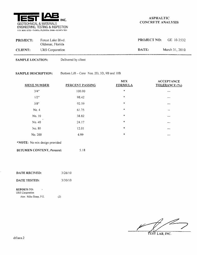
7.0 LABORATORY TESTING 7.1 General Classification tests, including percentage finer than the U.S. #200 sieve, natural moisture content, and Atterberg limits, were performed on representative soil samples from each stratum encountered during the field investigation. Atterberg limits tests were also performed on three representative limerock base samples. Density tests were performed on two representative asphaltic concrete cores. Two composite samples, comprised of four representative cores each, were tested to evaluate the material gradation and bitumen content of the asphaltic concrete used in each of the structural course lifts. All laboratory testing was performed in general accordance with ASTM procedures. Individual results from all the testing are provided in Appendix B.

11 URS
7.2 Results A summary of the representative soils properties, along with AASHTO classifications and material descriptions, is presented on the Soil Boring Legend, Figure 3A. Seven identifiable soil strata were encountered during the site exploration, and based on laboratory test results, AASHTO classifications ranged from A-3, A-2-4, A-2-6, A-7-6, to A-8. Results from the limerock base tests indicated the material to be non-plastic. Gradation and bitumen content testing was performed on composite representative core samples from the top lift of the asphaltic concrete and from the bottom lift. The purpose of this testing was to confirm that the asphaltic concrete used on the project met the PC-1 requirements. Density testing was also performed. Results of the testing are shown in Table 2, Summary of Asphalt Pavement Core Testing Results. In addition, the gradation results are shown graphically in Figure 4, Summary of Asphalt Core Gradations. As can be seen in the table and figure, the material generally meets the PC-1 requirements although the composite sample from the top lift slightly exceeds the allowable percentage passing the #200 sieve and the bitumen content is slightly less than the minimum 5%.
8.0 DISCUSSION AND EVALUATION 8.1 General Based on the results of this study, it appears that the early pavement distress being experienced at Forest Lakes Boulevard is the result of several inter-related factors which primarily consist of poor surface drainage, relatively low permeability subgrade soils, and high groundwater levels. The asphaltic concrete and limerock base thickness and materials appear to be in general compliance with the project plans and specifications. As previously stated, 12 inches of LBR 40 Type B stabilization was required below the limerock base. The soil samples obtained from the auger borings within the pavement indicate that clay and occasionally some shell were used to provide stabilization in the material immediately below the base. However, the soils encountered in the auger borings sometimes contained lumps or balls of clay. FDOT specifications for stabilizing require that “clay lumps” be broken down or removed from the stabilized materials.

12 URS
It is our understanding that no specific pavement design was performed during the design phase of the Forest Lakes Boulevard project. However, based on Pinellas County Public Works Roadway Pavement Guidelines for various roadway classifications, the pavement section that was constructed (three inches of PC-1 over 10½ inches of limerock over 12 inches of stabilized subgrade) would normally be adequate for this type of roadway. 8.2 Likely Pavement Failure Mechanism The typically observed alligator cracking with some rutting in the wheelpaths is indicative of inadequate base or subgrade support. The clayey soils underlying the pavement and base should provide adequate support as long as they remain dry. However, inadequate drainage of water from the base and subgrade can lead to pavement problems as excess pore water pressures will develop under traffic loads resulting in subsequent softening of the subgrade. Although it appears that the original design provided adequate base clearance from the seasonal high groundwater levels, the soil types used as fill and as stabilizing material have relatively low permeabilities. Therefore, water infiltrating these materials as a result of inadequate surface drainage cannot be rapidly dissipated. In addition, the presence of relatively high ambient groundwater levels further diminishes the ability of the subgrade soils to drain. A comparison of the pavement conditions at the coring locations with the soil types, DCP penetration resistances, and groundwater levels encountered at each location generally indicates that areas with clayey soils (strata 3 and 4) and relatively high groundwater levels typically have lower DCP resistances in the limerock base and/or subgrade. These areas also tend to be the areas that exhibit the worst pavement conditions. 8.3 Contributors To Pavement Failure It appears that water is migrating into the pavement structure through a combination of surface infiltration, edge inflow, and from the underlying groundwater as discussed below. With respect to the underlying groundwater, as previously stated, the groundwater levels encountered during our site exploration were at or above seasonal high groundwater levels shown in the project construction plans. This could be due to the fact that the months preceding the site exploration were wetter than typical for this time of year or, in some cases, could be the result of water

13 URS
perched within the clayey soils. Regardless, the high groundwater could be reaching the subgrade and base material through capillary rise in these fine-grained soils. During our site reconnaissance, several instances of lack of maintenance of the existing stormwater control system were observed. This lack of maintenance could be contributing to edge inflow of water into the pavement base and subgrade. Some of the observations included ditch bottom inlet grates in need of clearing, pipes requiring desilting, roadside swales not draining to ditch bottom inlets (lack of swale in some cases), and roadway shoulders requiring maintenance/regrading to eliminate ponding water. These existing conditions allow water to pond against the roadway embankment which eventually weakens the pavement base and subgrade. Regarding surface infiltration, the most significant source of surface water infiltration appears to be the numerous cracks in the pavement surface. In addition, during our site reconnaissance, it was observed that most of the roadway medians were not properly filled and shaped and were ponding water. In several cases, the ponded median water was causing upward seepage at the interface of the concrete gutter and the asphalt pavement. This water is not only infiltrating the base and subgrade materials from below but also from above as the seepage water flows over the pavement and into existing surface cracks (Photos 6 and 7). All of these conditions will likely result in a continued cycle of deterioration of the pavement as the pavement subgrade and base weakens causing more cracking which allows more infiltration of water. To help reduce the rate of pavement deterioration, minimum recommended surface drainage maintenance activities are provided below. 8.4 Recommended Surface Drainage Maintenance Activities Based on our site reconnaissance and review of the as-built plans, the following items are recommended to help prevent surface drainage from further contributing to the pavement deterioration: Perform regular maintenance of the existing drainage system – clearing debris from grates,
de-silting existing pipes as needed, regular mowing, etc.

14 URS
Correct the grading of the roadside swales to eliminate standing water adjacent to the roadway pavement.
Correct the grading of the median and landscaped areas to prevent standing water in these areas adjacent to the curb and gutter and roadway pavement.
Check stormwater ponds for proper operation.
9.0 REMEDIATION ALTERNATIVES EVALUATED 9.1 General A major objective in pavement design should be to keep the base and subgrade materials from becoming saturated or exposed to constant high moisture levels. This can be accomplished by using materials that are not sensitive to the effects of moisture and by quickly removing moisture from the pavement system. Based on these considerations, we have evaluated several alternatives to provide long-term remediation as well as one option for temporary remediation which could serve as an interim solution. All of the long-term alternatives evaluated involve the removal and replacement of the existing pavement and base materials. Because Forest Lakes Boulevard is a highly-traveled roadway providing access to businesses and because maintenance of traffic may be difficult in some areas, all of the long-term options evaluated include the use of asphalt base (Type B-12.5) to reduce the time required for base construction. Another advantage of asphalt base is that the required thickness of asphalt base is less than that for a comparable limerock base which results in additional clearance between the bottom of the base and the seasonal high groundwater. In addition, in lieu of subgrade stabilization, the long-term options evaluated include the use of a relatively permeable granular subbase. The project construction plans indicate that the entire roadway will be widened to six lanes at some point in the future. The temporary remediation option consists of milling and resurfacing the existing roadway to provide a suitable riding surface until the widening can be constructed. Milling and resurfacing could also serve as an interim solution until sufficient funds are available for long-term remediation.

15 URS
The following sections provide discussions of the options evaluated along with our recommended alternative. All of the options discussed assume that appropriate maintenance activities will be performed to improve the existing surface drainage system. 9.2 Option 1 – Subgrade Excavation and Replacement Including Edgedrains This alternative consists of removing the existing pavement and base and then excavating the existing 12-inch stabilized subgrade as well as an additional six inches of embankment material. The excavation would then be backfilled with 18 inches of AASHTO A-3 material followed by six inches of granular subbase in lieu of stabilized subgrade. The pavement section would consist of six inches of asphalt base (Type B-12.5) with two inches of Type SP asphaltic structural course and one inch of FC-9.5 friction course. This option would result in no net change in the roadway profile or grade. The replacement pavement section is based on the construction of a new section that is approximately the structural equivalent of the existing section. In addition, for two-lane and multi-lane roads with design speeds of 35 to 45 miles per hour, the FDOT Flexible Pavement Design Manual (March 2008) requires a friction course of either FC-9.5 of FC-12.5. Forest Lakes Boulevard has a design speed of 45 miles per hour. The use of FC-9.5 satisfies the friction course requirement and provides one inch of structural support. Because the median includes significant landscaping as well as roadway lighting structures, excavation and replacement of the median soils is not practical. In addition, as discussed previously, there is a potential for lateral edge flow from outside the roadway. The use of relatively permeable material in the subgrade and subbase in conjunction with positive outfall to swales or drainage structures should prevent an accumulation of lateral edge flow as well as vertical infiltration from affecting the asphalt base. To provide assurance that the subgrade is being adequately drained, the design should include the use of edgedrains extending to a depth of at least two feet below the base located on each side of each roadway. Groundwater collected from the edgedrains would be piped to new or existing drainage structures for positive discharge.

16 URS
9.3 Option 1A – Subgrade Excavation and Replacement With No Edgedrains Consideration was also given to subgrade excavation and replacement, as described above, without the use of edgedrains. However, without the edgedrains there is a potential for water to “pool” beneath the pavement in some low areas which could lead to early pavement deterioration. To overcome this potential for water to collect in the subgrade, “daylighting” of the permeable replacement subgrade material to the adjacent roadway swales would be required. However, throughout much of the roadway length, the swales are relatively shallow and adequate “daylighting” may not be possible. In addition, this option would require significantly more excavation and replacement of subgrade/embankment material which would exceed the cost of the edgedrains. As such, this was not considered a feasible alternative. 9.4 Option 2 – Pavement Replacement - Granular Subbase w/Edgedrains Another option that was evaluated was the removal of the existing pavement and base and replacement with six inches of asphalt base (Type B-12.5) with two inches of Type SP asphaltic structural course and one inch of FC-9.5 friction course. The asphalt base would be underlain by six inches of granular subbase in lieu of stabilized subgrade. In addition, edgedrains would be included. The granular subbase and edgedrains should serve to remove lateral edge inflow However, without replacing the existing subgrade, positive under-pavement drainage cannot be assured. Since this option does not eliminate the cause of early pavement distress (i.e., lack of under-pavement drainage and poor subgrade support), it is not recommended. 9.5 Option 3 – Raise Existing Roadway Grade Another alternative that should keep the base and subgrade materials from becoming saturated or exposed to constant high moisture levels is to raise the grade of the existing roadway. This process would consist of removing existing pavement, base, curb and gutter, and sidewalks and then raising the entire cross section by one foot with suitable material. The pavement section would then be constructed with six inches of granular subbase followed by six inches of asphalt base (Type B-12.5). The structural course would consist of two inches of Type SP asphaltic concrete and one inch of FC-9.5 friction course. Replacement of curb and gutter and sidewalks would also be required.

17 URS
Although this would likely be an effective solution, some issues that will require consideration include: Driveways and side road profiles will need to be modified to fit the new profile for the
roadway. This could involve extending work back into subdivision entrance areas or sideroads or potentially off the right-of-way at driveways.
The drainage structures will need to be adjusted accordingly for the new profile.
Clearances for any signals or signs may need adjustment, if applicable.
Changing the profile may potentially get the Southwest Florida Water Management District
(SWFWMD) involved, which could result in more stringent water quality requirements based on rule changes since the original project was permitted.
Addressing these issues in the design and construction of the roadway at a higher grade is likely to make this option cost prohibitive. 9.6 Option 4 – Mill and Resurface As previously mentioned, the project construction plans indicate that the entire roadway will be widened to six lanes at some point in the future. To save money and to provide a suitable riding surface until the widening can be constructed and the entire roadway can be remediated, milling and resurfacing the existing pavement may be an appropriate alternative. If widening is not in the foreseeable future, milling and resurfacing would provide a temporary solution until sufficient funds are available for long-term remediation of the roadway. Based on the results of coring, crack depths ranged from no crack to the full depth of asphalt. Therefore, milling the entire depth of asphaltic concrete appears to be appropriate. The asphalt could be replaced with two inches of Type SP asphaltic concrete and one inch of FC-9.5 friction course. With this option, it is likely that pavement distress will again manifest itself. However, with appropriate maintenance of the surface drainage system, it may not occur as quickly or be as

18 URS
severe. This option is not recommended unless there is a need to postpone a long-term solution until it can be funded. 9.7 Recommended Alternatives 9.7.1 Long-Term Remediation The results of this study indicate that the early pavement distress is primarily the result of the inability of the soils used as fill and stabilizing material to quickly dissipate water infiltrating as a result of inadequate surface drainage coupled with the presence of relatively high ambient groundwater levels. The inability of these materials to adequately drain can lead to pavement problems resulting from softening of the subgrade. Based on this conclusion, it appears that Option 1, discussed above, is the most appropriate remediation alternative to provide an effective long-term solution to the current pavement deterioration problems. Replacement of the existing stabilized subgrade and underlying six inches of embankment with relatively permeable material, along with the installation of edgedrains will allow for the quick removal of moisture from the pavement system. A conceptual typical section for this option is shown on Figure 6. A preliminary cost estimate was prepared for this option and is summarized below. Included is a preliminary cost estimate for the roadway items along with estimates of mobilization and maintenance of traffic costs. The estimated mobilization cost is assumed to be 10% of the roadway costs while the maintenance of traffic cost is estimated to be 20% of the roadway and mobilization costs. It should be noted that this cost estimate is for preliminary budgeting purposes only. Actual costs will depend on the final design of the selected remediation option.
Recommended Long-Term Remediation Option - Preliminary Cost Estimate Option
# Description Roadway Mobilization Maintenance of Traffic Total
1 $4,400,000 $440,000 $968,000 $5,808,000
12” Subgrade & 6” Embankment Excavation & Replacement
Including Edgedrains

19 URS
9.7.2 Temporary Repair As previously discussed, milling and resurfacing may be appropriate to save money and to provide a suitable riding surface until the widening can be constructed and the entire roadway remediated or to provide a temporary repair until sufficient funds are available for long-term remediation of the roadway. Based on these considerations, a budgetary estimate was prepared for milling and resurfacing assuming a milling depth of three inches and replacement of the milled pavement with two inches of Type SP asphaltic concrete and one inch of FC-9.5 friction course. The estimate is summarized below. As was done previously, the estimated mobilization cost is assumed to be 10% of the roadway costs while the maintenance of traffic cost is estimated to be 20% of the roadway and mobilization costs.
Temporary Repair Option - Preliminary Cost Estimate
Option # Description Roadway Mobilization Maintenance
of Traffic Total
4 $1,280,000 $128,500 $281,600 $1,689,600
Mill and Resurface Existing Pavement
9.8 Recommended Maintenance To improve surface drainage conditions and to potentially reduce the rate of pavement deterioration, implementation of the surface drainage maintenance activities discussed in Section 8.4 of this report is recommended.
10.0 LIMITATIONS OF THE REPORT This study has been conducted in accordance with generally accepted standards in the geotechnical engineering profession. No other warranty, expressed or implied is made.

PHOTOGRAPHS

Photo 1 – Typical Alligator Cracking
Photo 2 – Alligator Cracking With Spalling

Photo 3 – Area of Significant Patching
Photo 4 – Ponded Water Against Curb

Photo 5 – Ponded Water Along Intersection Radius
Photo 6 – Typical Ponded Water in Median

Photo 7 – Seepage From Median Ponded Water
Photo 8 – Typical Ditch Bottom Inlet Grate Requiring Maintenance

Photo 9 – Roadside Swale Requiring Mowing
Photo 10 – Standing Water in Roadside Swale

Photo 11 – Standing Water in Roadside Swale – Appears Higher Than Adjacent Pond
Photo 12 – Standing Water, Swale Not Apparent

Photo 13 – Pond 4A – Appears to be Staging Above Design High Water Elevation
Photo 14 – Pond 4A – Appears to be Staging Above DHW Elevation

Photo 15 – Ditch Bottom Inlet Not Draining Due to Pond 5 Above DHW Elevation

TABLES

Section Location (1)
1B 2.8 1.2 1.6 Yes 2.8 15.21D 2.6 1.6 1.0 Yes 0.0 12.42B 3.0 1.5 1.5 Yes 1.5 11.02D 2.5 1.0 1.5 Yes 2.5 13.53B 3.0 1.5 1.5 No 3.0 13.0 Bottom lift fragmented during coring3D 3.0 1.5 1.5 Yes 0.0 12.04B 3.0 1.5 1.5 No 1.5 11.04D 3.0 1.0 2.0 Yes 3.0 12.05B 3.0 1.5 1.5 Yes 0.0 12.05D -- 1.5 -- No 3.0 12.0 Bottom lift highly fragmented during coring6B 3.0 1.3 1.7 Yes 1.3 11.06D 3.2 1.7 1.5 Yes 3.2 11.87B 3.0 1.5 1.5 No 1.5 11.07D 2.7 1.2 1.5 Yes 0.0 13.38B -- -- 1.7 No 1.5 12.0 Top lift highly fragmented during coring8D 3.0 1.3 1.7 No 3.0 13.09B 2.8 1.3 1.5 No 1.5 13.29D 2.7 1.2 1.5 No 2.7 12.310B 2.7 1.2 1.5 Yes 2.7 11.310D 2.7 1.3 1.4 Yes 1.3 12.311B 3.0 1.3 1.8 No 3.0 11.011D 3.0 1.5 1.5 No 1.5 12.012B 3.0 1.5 1.5 Yes 0.0 12.012D 2.8 1.5 1.3 No 2.8 12.2
Average: 2.9 1.8 12.2
(1) B - Denotes core taken in eastbound roadway D - Denotes core taken in westbound roadway
12
Summary of Pavement Coring Results
Forest Lakes Boulevard Pavement EvaluationPinellas County
8
9
10
11
4
5
6
7
1
Crack Depth (in)
2
3
Bottom Lift Thickness
(in)
Core LocationLifts Intact
Table 1
Limerock Base Thickness
(in)Comments
Total Core Thickness
(in)
Top Lift Thickness
(in)

Sample Identification: Top Lift - Cores #2D, #3D, #9B, and #10B
Allowable RangeSieve # % Passing
3/4" 100 100 - 1001/2" 96.8 88 - 1003/8" 88.4 75 - 93
No. 4 55.3 47 - 75No. 10 35.1 31 - 53No. 40 24.7 19 - 35No. 80 13.8 7 - 21No. 200 7.1 2 - 6
Allowable RangeBitumen Content: 4.7% 5 - 9
Core Density: 136.2 lbs/ft3
Sample Identification: Bottom Lift - Cores #2D, #3D, #9B, and #10B
Allowable RangeSieve # % Passing
3/4" 100 100 - 1001/2" 98.4 88 - 1003/8" 92.6 75 - 93
No. 4 61.8 47 - 75No. 10 38.8 31 - 53No. 40 24.2 19 - 35No. 80 12 7 - 21No. 200 5 2 - 6
Allowable RangeBitumen Content: 5.2% 5 - 9
Core Density: 135.1 lbs/ft3
Summary of Asphalt Pavement Core Testing Results
Pinellas CountyForest Lakes Boulevard Pavement Evaluation
Table 2
% Passing
% Passing

FIGURES


URS Corporation FIGURE 5
Summary of Asphalt Core TestingGradation
Forest Lakes Boulevard Pavement Evaluation
0
10
20
30
40
50
60
70
80
90
100
Sieve Size
% P
assi
ng
Top Lift - Cores #2D, #3D, #9B, and #10B Bottom Lift - Cores #2D, #3D, #9B, and #10B Allowable Range
3/4" 1/2" 3/8" No. 4 No.10 No. 40 No. 80 No. 200


APPENDIX A
SUMMARY OF DYNAMIC CONE PENETROMETER RESULTS
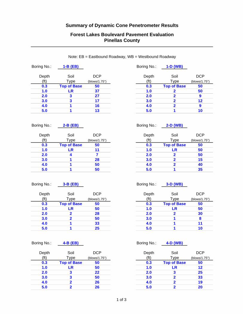
Boring No.: 1-B (EB) Boring No.: 1-D (WB)
Depth Soil DCP Depth Soil DCP(ft) Type (blows/1.75") (ft) Type (blows/1.75")0.3 Top of Base 50 0.3 Top of Base 501.0 LR 37 1.0 2 502.0 3 27 2.0 2 93.0 3 17 3.0 2 124.0 1 16 4.0 2 95.0 1 13 5.0 1 10
Boring No.: 2-B (EB) Boring No.: 2-D (WB)
Depth Soil DCP Depth Soil DCP(ft) Type (blows/1.75") (ft) Type (blows/1.75")0.3 Top of Base 50 0.3 Top of Base 501.0 LR 11 1.0 LR 502.0 4 7 2.0 2 503.0 1 28 3.0 2 154.0 1 50 4.0 2 405.0 1 50 5.0 1 35
Boring No.: 3-B (EB) Boring No.: 3-D (WB)
Depth Soil DCP Depth Soil DCP(ft) Type (blows/1.75") (ft) Type (blows/1.75")0.3 Top of Base 50 0.3 Top of Base 501.0 LR 50 1.0 LR 502.0 2 28 2.0 2 303.0 2 50 3.0 1 84.0 1 33 4.0 1 115.0 1 25 5.0 1 10
Boring No.: 4-B (EB) Boring No.: 4-D (WB)
Depth Soil DCP Depth Soil DCP(ft) Type (blows/1.75") (ft) Type (blows/1.75")0.3 Top of Base 50 0.3 Top of Base 501.0 LR 50 1.0 LR 122.0 3 22 2.0 3 253.0 3 50 3.0 2 334.0 2 26 4.0 2 195.0 2 26 5.0 2 20
Summary of Dynamic Cone Penetrometer Results
Forest Lakes Boulevard Pavement EvaluationPinellas County
Note: EB = Eastbound Roadway, WB = Westbound Roadway
1 of 3

Summary of Dynamic Cone Penetrometer Results
Forest Lakes Boulevard Pavement EvaluationPinellas County
Note: EB = Eastbound Roadway, WB = Westbound Roadway
Boring No.: 5-B (EB) Boring No.: 5-D (WB)
Depth Soil DCP Depth Soil DCP(ft) Type (blows/1.75") (ft) Type (blows/1.75")0.3 Top of Base 50 0.3 Top of Base 501.0 LR 50 1.0 LR 302.0 3 22 2.0 3 193.0 3 50 3.0 3 134.0 1 32 4.0 3 105.0 1 19 5.0 3 7
Boring No.: 6-B (EB) Boring No.: 6-D (WB)
Depth Soil DCP Depth Soil DCP(ft) Type (blows/1.75") (ft) Type (blows/1.75")0.3 Top of Base 50 0.3 Top of Base 501.0 LR 19 1.0 LR 502.0 3 9 2.0 3 293.0 3 50 3.0 3 504.0 1 50 4.0 1 375.0 1 36 5.0 1 18
Boring No.: 7-B (EB) Boring No.: 7-D (WB)
Depth Soil DCP Depth Soil DCP(ft) Type (blows/1.75") (ft) Type (blows/1.75")0.3 Top of Base 50 0.3 Top of Base 501.0 LR 32 1.0 LR 502.0 3 43 2.0 3 503.0 1 50 3.0 1 314.0 1 50 4.0 1 505.0 1 50 5.0 1 50
Boring No.: 8-B (EB) Boring No.: 8-D (WB)
Depth Soil DCP Depth Soil DCP(ft) Type (blows/1.75") (ft) Type (blows/1.75")0.3 Top of Base 50 0.3 Top of Base 501.0 LR 18 1.0 LR 502.0 3 50 2.0 3 503.0 2 50 3.0 3 314.0 2 50 4.0 3 315.0 2 50 5.0 3 50
2 of 3

Summary of Dynamic Cone Penetrometer Results
Forest Lakes Boulevard Pavement EvaluationPinellas County
Note: EB = Eastbound Roadway, WB = Westbound Roadway
Boring No.: 9-B (EB) Boring No.: 9-D (WB)
Depth Soil DCP Depth Soil DCP(ft) Type (blows/1.75") (ft) Type (blows/1.75")0.3 Top of Base 50 0.3 Top of Base 501.0 LR 50 1.0 LR 502.0 3 32 2.0 3 503.0 2 50 3.0 1 504.0 2 50 4.0 1 505.0 2 50 5.0 1 50
Boring No.: 10-B (EB) Boring No.: 10-D (WB)
Depth Soil DCP Depth Soil DCP(ft) Type (blows/1.75") (ft) Type (blows/1.75")0.3 Top of Base 50 0.3 Top of Base 501.0 LR 50 1.0 LR 502.0 3 50 2.0 2 253.0 1 50 3.0 1 504.0 1 50 4.0 1 505.0 1 50 5.0 1 30
Boring No.: 11-B (EB) Boring No.: 11-D (WB)
Depth Soil DCP Depth Soil DCP(ft) Type (blows/1.75") (ft) Type (blows/1.75")0.3 Top of Base 50 0.3 Top of Base 501.0 LR 50 1.0 LR 502.0 2 35 2.0 2 263.0 2 50 3.0 1 504.0 4 50 4.0 1 335.0 4 17 5.0 1 50
Boring No.: 12-B (EB) Boring No.: 12-D (WB)
Depth Soil DCP Depth Soil DCP(ft) Type (blows/1.75") (ft) Type (blows/1.75")0.3 Top of Base 50 0.3 Top of Base 501.0 LR 50 1.0 LR 502.0 3 27 2.0 2 213.0 1 50 3.0 1 304.0 1 33 4.0 1 395.0 1 50 5.0 1 50
3 of 3

APPENDIX B
LABORATORY TESTING RESULTS