engineering services facility university of tennessee...
TRANSCRIPT

ENGINEERING SERVICES FACILITY University of Tennessee Knoxville
SBC No. 540/009-05-2016
SCHEMATIC DESIGN SUBMITTAL
Outline Specifications + Narratives
December 14, 2017
McCarty Holsaple McCarty Inc. Architects & Interior Designers In collaboration with SmithGroup JJR

Schematic Design Submittal Engineering Services FacilityUniversity of Tennessee Knoxville
SBC No. 540/009-05-2016
Knoxville, TN
12/14/17 1 PROJECT TITLE PAGE
SECTION 00.01.01
PROJECT TITLE PAGE
SCHEMATIC DESIGN SUBMITTAL | OUTLINE SPECIFICATIONS + NARRATIVES
FOR
UTK ENGINEERING SERVICES FACILITY | SBC NO. 540/009-05-2016
ARCHITECT'S PROJECT NUMBER: 17004
UNIVERSITY OF TENNESSEE, KNOXVILLE
ESTABROOK DRIVE
UNIVERSITY OF TENNESSEE
KNOXVILLE , TENNESSEE 37916
DATE: DECEMBER 14, 2017
PREPARED BY:
MCCARTY HOLSAPLE MCCARTY ARCHITECTS & INTERIOR DESIGNERS
IN COLLABORATION WITH SMITHGROUP JJR
END OF SECTION

Schematic Design Submittal Engineering Services FacilityUniversity of Tennessee Knoxville
SBC No. 540/009-05-2016
Knoxville, TN
12/14/17 1 PROJECT DIRECTORY
SECTION 00.01.03
PROJECT DIRECTORY
PART 1 GENERAL
1.01 SECTION INCLUDES
A. Identification of project team members and their contact information.
1.02 OWNER:
A. Name: University of Tennessee.
1. City: Knoxville.
2. State: Tennessee.
1.03 CONSULTANTS:
A. Architect: Design Professional of Record. All correspondence from the Contractor regardingconstruction documents authored by Architect's consultants will be through this party, unlessalternate arrangements are mutually agreed upon at preconstruction meeting.
1. Company Name: McCarty Holsaple McCarty Inc. Architects and Interior Designers.
a. Address: 550 W. Main Street, Suite 300.
b. City: Knoxville.
c. State: Tennessee.
d. Zip Code: 37902.
e. Telephone: (865) 544-2000.
B. Lab Building Design Consultant:
1. Company Name: SmithGroup JJR.
a. Address: 201 Depot Street.
b. City: Ann Arbor.
c. State: Michigan.
d. Zip Code: 48104.
e. Telephone: (734) 662-4457.
C. Civil Engineering Consultant:
1. Company Name: Civil & Environmental Consultants Inc. (CEC).
a. Address: 2704 Cherokee Farm Way, Suite 101.
b. City: Knoxville.
c. State: Tennessee.
d. Zip Code: 37920.
e. Telephone: (865) 977-9997.
D. Landscape Architecture Consultant:
1. Company Name: Ross/ Fowler.
a. Address: 5103 Kingston Pike, Suite 105.
b. City: Knoxville.
c. State: Tennessee.
d. Zip Code: 37919.
e. Telephone: (865) 637-1100.
E. Structural Engineering Consultant:
1. Company Name: RBA Structural Engineering.
a. Address: 227 French Landing Road, Suite 500.
b. City: Nashville.
c. State: Tennessee.
d. Zip Code: 37228.
e. Telephone: (615) 329-1300.
F. Mechanical, Electrical, Plumbing + Fire Protection Engineering Consultant:
1. Company Name: Newcomb & Boyd.

Schematic Design Submittal Engineering Services FacilityUniversity of Tennessee Knoxville
SBC No. 540/009-05-2016
Knoxville, TN
12/14/17 2 PROJECT DIRECTORY
a. Address: 303 Peachtree Center Avenue NE #525.
b. City: Atlanta.
c. State: Georgia.
d. Zip Code: 30303.
e. Telephone: (404) 730-8400.
G. Low Voltage/ Communications Consultant:
1. Company Name: West Welch Reed Engineers.
a. Address: 5417 Ball Camp Road.
b. City: Knoxville.
c. State: Tennessee.
d. Zip Code: 37921.
e. Telephone: (865) 588-2431.
H. Constructability/ Scheduling Consultant:
1. Company Name: Don Freeman/ MHM Consultant.
a. Telephone: (865) 546-2440.
I. Nuclear Shielding Consultant:
1. Company Name: AECOM.
a. Address: 2131 South Centennial Avenue, Bldg CCC3.
b. City: Aiken.
c. State: South Carolina.
d. Zip Code: 29803.
e. Telephone: (803) 502-9767.
J. Cost Estimating:
1. Company Name: Palacio Collaborative.
a. Address: 400 Galleria Pkwy SE, S-1500.
b. City: Atlanta.
c. State: Georgia.
d. Zip Code: 30339.
e. Telephone: (404) 609-9006.
PART 2 PRODUCTS - NOT USED
PART 3 EXECUTION - NOT USED
END OF SECTION

Schematic Design Submittal Engineering Services FacilityUniversity of Tennessee Knoxville
SBC No. 540/009-05-2016
Knoxville, TN
12/14/17 1 TABLE OF CONTENTS
SECTION 00.01.10
TABLE OF CONTENTS
PROCUREMENT AND CONTRACTING REQUIREMENTS
1.01 DIVISION 00 -- PROCUREMENT AND CONTRACTING REQUIREMENTS
A. 00.01.01 - Project Title Page
B. 00.01.03 - Project Directory
C. 00.01.10 - Table of Contents
SPECIFICATIONS
2.01 DIVISION 01 -- GENERAL REQUIREMENTS
A. 01.23.00 - Alternates
B. 01.45.33 - Code-Required Special Inspections
2.02 DIVISION 02 -- EXISTING CONDITIONS
A. 02.41.00 - Demolition
B. 02.41.19 - Selective Demolition
2.03 DIVISION 03 -- CONCRETE
A. 03.20.00 - Concrete Reinforcing
B. 03.30.00 - Cast-in-Place Concrete
C. 03 35 43 - Polished Concrete Finishing
D. 03.38.00 - Post-Tensioned Concrete
2.04 DIVISION 04 -- MASONRY
A. 04.20.00 - Unit Masonry
B. 04.20.01 - Masonry Veneer
C. 04.43.01 - Stone Masonry Veneer
2.05 DIVISION 05 -- METALS
A. 05.12.00 - Structural Steel Framing
B. 05.31.00 - Steel Decking
C. 05.50.00 - Metal Fabrications
D. 05.51.00 - Metal Stairs
E. 05.52.13 - Pipe and Tube Railings
F. 05.71.00 - Decorative Metal Stairs
G. 05.73.00 - Decorative Metal Railings
2.06 DIVISION 06 -- WOOD, PLASTICS, AND COMPOSITES
A. 06.10.53 - Miscellaneous Rough Carpentry
B. 06.41.13 - Wood Veneer-Faced Architectural Cabinets
C. 06.41.16 - lastic Laminate-Faced Architectural Cabinets
D. 06.74.13 - Fiberglass Reinforced Gratings
2.07 DIVISION 07 -- THERMAL AND MOISTURE PROTECTION
A. 07.11.13 - Bituminous Dampproofing
B. 07.14.13 - Hot Fluid-Applied Rubberized Asphalt Waterproofing
C. 07.16.19 - Metal Oxide Waterproofing
D. 07.21.00 - Thermal Insulation

Schematic Design Submittal Engineering Services FacilityUniversity of Tennessee Knoxville
SBC No. 540/009-05-2016
Knoxville, TN
12/14/17 2 TABLE OF CONTENTS
E. 07 27 26 - Fluid-Applied Membrane Air Barriers
F. 07.32.13 - Clay Roof Tiles
G. 07.43.13.13 - Formed Metal Wall Panels
H. 07.52.16 - Styrene-Butadiene-Styrene Modified Bituminous Roofing (SBS)
I. 07.62.00 - Sheet Metal Flashing and Trim
J. 07.71.00 - Roof Specialties
K. 07.72.00 - Roof Accessories
L. 07.72.73 - Vegetated Roof Systems
M. 07.84.13 - Penetration Firestopping
N. 07.84.43 - Joint Firestopping
O. 07.92.00 - Joint Sealants
2.08 DIVISION 08 -- OPENINGS
A. 08.11.13 - Hollow Metal Doors and Frames
B. 08.12.16 - Aluminum Frames
C. 08.14.16 - Flush Wood Doors
D. 08.31.13 - Access Doors and Frames
E. 08.33.23 - Overhead Coiling Doors
F. 08.36.13 - Sectional Doors
G. 08.41.13 - Aluminum-Framed Entrances and Storefronts
H. 08.44.13 - Glazed Aluminum Curtain Walls
I. 08.71.11 - Door Hardware (Descriptive Specification)
J. 08.71.13 - Automatic Door Operators
K. 08.80.00 - Glazing
L. 08.83.00 - Mirrors
M. 08.88.13 - Fire-Resistant Glazing
N. 08.91.19 - Fixed Louvers
2.09 DIVISION 09 -- FINISHES
A. 09.21.16.23 - Gypsum Board Shaft Wall Assemblies
B. 09.22.16 - Non-Structural Metal Framing
C. 09.29.00 - Gypsum Board
D. 09.30.13 - Ceramic Tiling
E. 09.51.00 - Acoustical Ceilings
F. 09.65.13 - Resilient Base and Accessories
G. 09.65.16 - Resilient Sheet Flooring
H. 09.65.16.13 - Linoleum Flooring
I. 09.65.36 - Static Control Resilient Flooring
J. 09.67.23 - Resinous Flooring
K. 09.68.13 - Tile Carpeting
L. 09.91.13 - Exterior Painting
M. 09.91.23 - Interior Painting
N. 09.96.00 - High-Performance Coatings

Schematic Design Submittal Engineering Services FacilityUniversity of Tennessee Knoxville
SBC No. 540/009-05-2016
Knoxville, TN
12/14/17 3 TABLE OF CONTENTS
2.10 DIVISION 10 -- SPECIALTIES
A. 10.11.00 - Visual Display Units
B. 10.14.23 - Panel Signage
C. 10.21.13.14 - Stainless Steel Toilet Compartments
D. 10.22.39 - Folding Panel Partitions
E. 10.26.00 - Wall and Door Protection
F. 10.28.00 - Toilet, Bath, and Laundry Accessories
G. 10.44.13 - Fire Protection Cabinets
H. 10.44.16 - Fire Extinguishers
2.11 DIVISION 11 -- EQUIPMENT
A. 11.13.00 - Loading Dock Equipment
2.12 DIVISION 12 -- FURNISHINGS
A. 12.21.13 - Horizontal Louver Blinds
B. 12.24.13 - Roller Window Shades
C. 12.48.16 - Entrance Floor Grilles
2.13 DIVISION 13 -- SPECIAL CONSTRUCTION
A. 13.21.13.33 - Cleanroom Wall System (CRPS)
B. 13.27.00 - Vaults
C. 13.49.00 - Radiation Protection
2.14 DIVISION 14 -- CONVEYING EQUIPMENT
14.21.00 - Electric Traction Elevators
2.15 DIVISION 21 -- FIRE SUPPRESSION
2.16 DIVISION 22 -- PLUMBING
A. Refer to attached narrative
2.17 DIVISION 23 -- HEATING, VENTILATING, AND AIR-CONDITIONING (HVAC)
A. Refer to attached narrative
2.18 DIVISION 26 -- ELECTRICAL
A. Refer to attached narrative
2.19 DIVISION 27 -- COMMUNICATIONS
A. 27.13.13 - Structured Cabling System
B. 27.41.00 - Audio/ Visual Systems
C. 27.53.13 - Synchronized Clocks
D. 27.53.19 - Distributed Antenna System
2.20 DIVISION 28 -- ELECTRONIC SAFETY AND SECURITY
A. 28.16.00 - Access Control/ Intrusion Detection System
B. 28.23.00 - CCTV System
2.21 DIVISION 31 -- EARTHWORK
A. 31.63.29 - Drilled Concrete Piers and Shafts
2.22 DIVISION 32 -- EXTERIOR IMPROVEMENTS
A. Refer to notes on SD Drawings

Schematic Design Submittal Engineering Services FacilityUniversity of Tennessee Knoxville
SBC No. 540/009-05-2016
Knoxville, TN
12/14/17 4 TABLE OF CONTENTS
2.23 DIVISION 33 -- UTILITIES
A. Refer to notes on SD Drawings
2.24 SCHEMATIC DESIGN ARCHITECTURAL NARRATIVE - SMITHGROUP JJR
2.25 SCHEMATIC DESIGN CIVIL/ SITEWORK NARRATIVE
2.26 SCHEMATIC DESIGN LANDSCAPE/ HARDSCAPE NARRATIVE
2.27 SCHEMATIC STRUCTURAL NARRATIVE - RBA STRUCTURAL ENGINEERING
2.28 STRUCTURAL: ESTIMATED CAISSON QUANTITIES
2.29 MECHANICAL & ELECTRICAL DESCRIPTION OF SYSTEMS - NEWCOMB & BOYD
CONSULTANTS AND ENGINEERS
2.30 LOW VOLTAGE NARRATIVE + COST ESTIMATES - WWR ENGINEERS
2.31 SCHEMATIC DESIGN CIVIL/ SITEWORK PRICING NARRATIVE
2.32 SCHEMATIC DESIGN LANDSCAPE/ HARDSCAPE NARRATIVE
2.33 HPBR CHECKLIST - SCHEMATIC DESIGN PHASE
END OF SECTION

Schematic Design Submittal Engineering Services FacilityUniversity of Tennessee Knoxville
SBC No. 540/009-05-2016
Knoxville, TN
12/14/17 1 ALTERNATES
SECTION 01.23.00
ALTERNATES
PART 1 GENERAL
1.01 SECTION INCLUDES
A. Description of Alternates.
1.02 SCHEDULE OF ALTERNATES
A. Stormwater Alternates ____ - ______________
1. Base: Green roof with 12” soil and associated structural increases; purchase remainingcredits.
2. Green Roof Alternate 1a: Purchase full credit to handle site storm water and providesmall water quality units as described in Civil Narrative.
B. Landscape Alternate ____ - ______________:
1. Base Price: Confine work on Estabrook Road to tie the plaza into the existing steps/curbs,etc. per attached sketch.
2. Landscaping Alternate 1: Build the new steps as illustrated on the site plan; remove theparallel parking from Lower Drive and construct a connecting sidewalk from ESF/ Ticklebridge westward to Neyland Stadium; include striping of crosswalks across Lower Drive tothe next pedestrian right of way.
C. Wall Assembly Alternates ____ - ______________:
1. Base Price: 1 ½” air space with continuous mortar netting over 2 ½” rigid insulation overfluid applied AVB on 5/8” exterior sheathing. Include cost to cut bricks or use specialshape bricks at reveals; include cost of spray foam insulation for 5-10% of wall areas.
2. Wall Assembly Alternate 1: Reduce rigid insulation to 2” and replace continuous mortarnetting with 1” cavity netting at base of assembly (all horizontal interruptions); Distancefrom face of brick to face of stud remains the same, with larger resulting air space; exteriorsheathing and AVB remains the same; Add 1 ½” spray foam insulation to back side of gypboard. Reduce dry-in time during construction by (x) months.
3. Wall Assembly Alternate 2: Fiberglass Z clip system similar to SMARTci or Knightwall forthermally broken brick and stone veneer fasteners at every stud (16” centers). Shorter tiedepths and reduced construction time by (x) months.
4. Wall Assembly Alternate 3: Relief angle brackets system similar to Hohmann Bernard orFero Shelf bracket at every floor level; reduce steel relief angles from 4x7 to 4x4 andreduce construction time by (x) months.
D. Mechanical: Energy Recovery Alternate ____ - ______________
1. Base Price: Provide standard runaround-type energy recovery system to recovery heatbetween laboratory exhaust and outside air streams. Energy recovery coils provided byAHU manufacturer (Carrier, JCI or Trane). Pumps provided by Armstrong, Bell & Gossettor Taco. Controls provided building control system manufacturer (JCI or SchneiderElectric).
2. Alternate 1: Provide integrated, high-efficiency runaround-type energy recovery system torecovery heat between laboratory exhaust and outside air streams. Energy recovery coilsprovided by Konvekta. Pumps and controls combined on a hydronic module packagedskid and provided by Konvekta.
PART 2 PRODUCTS - NOT USED
PART 3 EXECUTION - NOT USED
END OF SECTION

Schematic Design Submittal Engineering Services FacilityUniversity of Tennessee Knoxville
SBC No. 540/009-05-2016
Knoxville, TN
12/14/17 1 CODE-REQUIRED SPECIALINSPECTIONS
SECTION 01.45.33
CODE-REQUIRED SPECIAL INSPECTIONS
PART 1 GENERAL
1.01 REFERENCE STANDARDS
A. ACI 318 - Building Code Requirements for Structural Concrete and Commentary; 2014 (Errata2017).
B. AISC 360 - Specification for Structural Steel Buildings; 2010.
C. ASTM D3740 - Standard Practice for Minimum Requirements for Agencies Engaged in theTesting and/or Inspection of Soil and Rock as Used in Engineering Design and Construction;2012a.
D. ASTM E736/E736M - Standard Test Method for Cohesion/Adhesion of Sprayed Fire-ResistiveMaterials Applied to Structural Members; 2000 (2015)e1.
E. ASTM E2174 - Standard Practice for On-Site Inspection of Installed Firestops; 2014b.
F. ASTM E2393 - Standard Practice for On-Site Inspection of Installed Fire Resistive JointSystems and Perimeter Fire Barriers; 2010a (Reapproved 2015).
G. AWCI 117 - Technical Manual 12-B; Standard Practice for the Testing and Inspection of FieldApplied Thin Film Intumescent Fire-Resistive Materials; an Annotated Guide; 2014.
H. AWS D1.1/D1.1M - Structural Welding Code - Steel; 2015 (with March 2016 Errata).
I. AWS D1.3/D1.3M - Structural Welding Code - Sheet Steel; 2008.
J. AWS D1.4/D1.4M - Structural Welding Code - Reinforcing Steel; 2011.
PART 2 PRODUCTS - NOT USED
PART 3 EXECUTION
3.01 SPECIAL INSPECTIONS FOR STEEL CONSTRUCTION
A. High-Strength Bolt, Nut and Washer Material:
1. Verify identification markings conform to ASTM standards specified in the approvedcontract and to AISC 360, Section A3.3; periodic.
2. Submit manufacturer's certificates of compliance; periodic.
B. High-Strength Bolting Installation: Verify items listed below comply with AISC 360, SectionM2.5.
1. Snug tight joints; periodic.
C. Structural Steel and Cold Formed Steel Deck Material:
1. Structural Steel: Verify identification markings conform to AISC 360, Section M3.5;periodic.
2. Other Steel: Verify identification markings conform to ASTM standards specified in theapproved contract documents; periodic.
3. Submit manufacturer's certificates of compliance and test reports; periodic.
D. Weld Filler Material:
1. Verify identification markings conform to AWS standards specified in the approvedcontract documents and to AISC 360, Section A3.5; periodic.
2. Submit manufacturer's certificates of compliance; periodic.
E. Welding:
1. Structural Steel and Cold Formed Steel Deck:
a. Complete and Partial Joint Penetration Groove Welds: Verify compliance with AWSD1.1/D1.1M; continuous.
b. Multipass Fillet Welds: Verify compliance with AWS D1.1/D1.1M; continuous.
c. Single Pass Fillet Welds Less than 5/16 inch Wide: Verify compliance with AWSD1.1/D1.1M; periodic.
Schematic Design Submittal Engineering Services FacilityUniversity of Tennessee Knoxville
SBC No. 540/009-05-2016
Knoxville, TN
12/14/17 2 CODE-REQUIRED SPECIALINSPECTIONS
d. Plug and Slot Welds: Verify compliance with AWS D1.1/D1.1M; continuous.
e. Single Pass Fillet Welds 5/16 inch or Greater: Verify compliance with AWSD1.1/D1.1M; continuous.
f. Floor and Roof Deck Welds: Verify compliance with AWS D1.3/D1.3M; continuous.
2. Reinforcing Steel: Verify items listed below comply with AWS D1.4/D1.4M and ACI 318,Section 3.5.2.
a. Verification of weldability; periodic.
b. Reinforcing steel resisting flexural and axial forces in intermediate and specialmoment frames as well as boundary elements of special structural walls of concreteand shear reinforcement; continuous.
c. Shear reinforcement; continuous.
d. Other reinforcing steel; periodic.
F. Steel Frame Joint Details: Verify compliance with approved contract documents.
1. Details, bracing and stiffening; periodic.
2. Member locations; periodic.
3. Application of joint details at each connection; periodic.
G. Cold formed steel trusses spanning 60 feet or more; periodic.
3.02 SPECIAL INSPECTIONS FOR CONCRETE CONSTRUCTION
A. Reinforcing Steel, Including Prestressing of Tendons and Placement: Verify compliance withapproved contract documents and ACI 318, Sections 3.5 and 7.1 through 7.7; periodic.
B. Reinforcing Steel Welding: Verify compliance with AWS D1.4/D1.4M and ACI 318, Section3.5.2; periodic.
C. Design Mix: Verify plastic concrete complies with the design mix in approved contractdocuments and with ACI 318, Chapter 4 and 5.2; periodic.
D. Specified Curing Temperature and Techniques: Verify compliance with approved contractdocuments and ACI 318, Sections 5.11 through 5.13; periodic.
E. Concrete Strength in Situ: Verify concrete strength complies with approved contract documentsand ACI 318, Section 6.2, for the following.
F. Formwork Shape, Location and Dimensions: Verify compliance with approved contractdocuments and ACI 318, Section 6.1.1; periodic.
3.03 SPECIAL INSPECTIONS FOR SOILS
A. Materials and Placement: Verify each item below complies with approved constructiondocuments and approved geotechnical report.
1. Design bearing capacity of material below shallow foundations; periodic.
2. Design depth of excavations and suitability of material at bottom of excavations; periodic.
3. Materials, densities, lift thicknesses; placement and compaction of backfill: continuous.
4. Subgrade, prior to placement of compacted fill; periodic.
B. Testing: Classify and test excavated material; periodic.
3.04 SPECIAL INSPECTIONS FOR CAST-IN-PLACE DEEP FOUNDATIONS
A. Materials, Equipment and Final Placement: Verify each item below complies with approvedconstruction documents and approved geotechnical report.
1. Element length; continuous.
2. Element diameters and bell diameters; continuous.
3. Embedment into bedrock; continuous.
4. End bearing strata capacity; continuous.
5. Placement locations and plumbness; continuous.
6. Type and size of hammer; continuous.
B. Drilling Operations: Observe and maintain complete and accurate records for each element;continuous.

Schematic Design Submittal Engineering Services FacilityUniversity of Tennessee Knoxville
SBC No. 540/009-05-2016
Knoxville, TN
12/14/17 3 CODE-REQUIRED SPECIALINSPECTIONS
C. Material Volume: Record concrete and grout volumes.
D. Concrete Elements Associated with Cast-in-Place Deep Foundations: Perform additionalinspections as required by the Special Inspections for Concrete Construction article of thissection.
3.05 SPECIAL INSPECTIONS FOR SPRAYED FIRE RESISTANT MATERIALS
A. Sprayed Fire Resistant Materials, General:
1. Verify compliance of sprayed-fire resistant materials with specific fire-rated assembliesindicated in approved contract documents, and with applicable requirements of the buildingcode.
2. Perform special inspections after rough installation of electrical, mechanical, plumbing,automatic fire sprinkler and suspension systems for ceilings.
B. Physical and visual tests: Verify compliance with fire resistance rating.
1. Condition of substrates; periodic.
2. Thickness of sprayed fire resistant material; periodic.
3. Density of sprayed fire resistant material in pounds per cubic foot; periodic.
4. Bond strength (adhesion and cohesion); periodic.
5. Condition of finished application; periodic.
C. Structural member surface conditions:
1. Inspect structural member surfaces before application of sprayed fire resistant materials;periodic.
2. Verify preparation of structural member surfaces complies with approved contractdocuments and manufacturer's written instructions; periodic.
D. Application:
1. Ensure minimum ambient temperature before and after application complies with themanufacturer's written instructions; periodic.
2. Verify area where sprayed fire resistant material is applied is ventilated as required by themanufacturer's written instructions during and after application; periodic.
E. Thickness: Verify that no more than 10 percent of thickness measurements taken from sprayedfire resistant material are less than thickness required by fire resistance design in approvedcontract documents. In no case shall the thickness of the sprayed fire resistant material be lessthan the minimum below.
1. Minimum Allowable Thickness: Tested according to ASTM E605/E605M, periodic.
F. Density: Verify density of sprayed fire resistant material is no less than density required by thefire resistance design in the approved contract documents.
G. Bond Strength: Verify adhesive and cohesive bond strength of sprayed fire resistant materialsis no less than 150 pounds per square foot when in-place samples of the cured material aretested according to ASTM E736/E736M and as described below.
3.06 SPECIAL INSPECTIONS FOR MASTIC AND INTUMESCENT FIRE RESISTANT COATINGS
A. Verify mastic and intumescent fire resistant coatings comply with AWCI 117 and the fireresistance rating indicated on approved contract documents.
3.07 SPECIAL INSPECTIONS FOR FIRE RESISTANT PENETRATIONS AND JOINTS
A. Verify penetration firestops in accordance with ASTM E2174.
B. Verify fire resistant joints in accordance with ASTM E2393.
3.08 SPECIAL INSPECTIONS FOR SMOKE CONTROL
A. Test smoke control systems as follows:
1. Record device locations and test system for leakage after erection of ductwork but beforestarting construction that conceals or blocks access to system.
2. Test and record pressure difference, flow measurements, detection function and controlsafter system is complete and before structure is occupied.

Schematic Design Submittal Engineering Services FacilityUniversity of Tennessee Knoxville
SBC No. 540/009-05-2016
Knoxville, TN
12/14/17 4 CODE-REQUIRED SPECIALINSPECTIONS
3.09 SPECIAL INSPECTIONS FOR SEISMIC RESISTANCE
A. Designated Seismic System Verification: Verify label, anchorage or mounting conforms tocertificate of compliance provided by manufacturer or fabricator.
B. Structural Observations for Seismic Resistance: Visually observe structural system for generalconformance with the approved contract documents; periodic.
3.10 SPECIAL INSPECTIONS FOR WIND RESISTANCE
A. Structural Observations for Wind Resistance: Visually observe structural system for generalconformance with the approved contract documents; periodic.
3.11 OTHER SPECIAL INSPECTIONS
A. Provide for special inspection of work that, in the opinion of the AHJ, is unusual in nature.
END OF SECTION

Schematic Design Submittal Engineering Services FacilityUniversity of Tennessee Knoxville
SBC No. 540/009-05-2016
Knoxville, TN
12/14/17 1 DEMOLITION
SECTION 02.41.00
DEMOLITION
PART 1 GENERAL
1.01 SECTION INCLUDES
A. Building demolition excluding removal of hazardous materials and toxic substances, includingthe removal of the following buildings: Estabrook Hall, Pasqua Hall, and Berry Hall.
B. Selective demolition of items in Estabrook Hall for incorporation into new design.
C. Abandonment and removal of existing utilities and utility structures.
D. Demolition will occur as an early-release package, after the hazardous materials abatement andprior to the deep foundation package.
END OF SECTION

Schematic Design Submittal Engineering Services FacilitiesUniversity of Tennessee Knoxville
SBC No. 540/009-05-2016
Knoxville, TN
SECTION 024119 - SELECTIVE DEMOLITION
1.1 PROJECT CONDITIONS
A. Hazardous Materials: Not expected Expected Unknown.
1. Remediation: By Owner before start of Work Contractor as part of this Project.2. Landfill records for hazardous wastes.
B. Historic removal or dismantling required.
1.2 WARRANTY
A. Existing Warranties: Insert list of existing warranties affected by selective demolition.
1.3 EXECUTION
A. Professional engineer engaged to survey condition of building.
1. Recorded by use of preconstruction photographs.
B. Utility Services and Mechanical/Electrical Systems: Maintained to occupied facilities.
1. Shut Off: By Owner Building manager Contractor.
C. Site Access and Temporary Controls: Minimum interference with roads, streets, walks, walkways, and other adjacent occupied and used facilities
D. Temporary Facilities:
1. Temporary barricades to prevent injury to people.2. Temporary weather protection.3. Protection of existing finish work to remain.4. Protection of furnishings and equipment.
E. Temporary shoring.
F. Removed and Salvaged Items: Cleaned, crated, stored, and transported to Owner's on off-site storage area.
G. Removed and Reinstalled Items: Cleaned, repaired, crated, stored, and reinstalled.
H. Existing Items to Remain: Existing construction protected against damage.
I. Disposal of Demolished Items:
1. Burning: Not permitted Permitted at designated areas.2. Disposal: At designated spoil areas on Off Owner's property.
END OF SECTION 024119
12/14/17 1 DIVISION 02 - EXISTING CONDITIONS

Schematic Design Submittal Engineering Services FacilityUniversity of Tennessee Knoxville
SBC No. 540/009-05-2016
Knoxville, TN
12/14/17 1 CONCRETE REINFORCING
SECTION 03.20.00
CONCRETE REINFORCING
PART 1 GENERAL
1.01 REFERENCE STANDARDS
A. ASTM A615/A615M - Standard Specification for Deformed and Plain Carbon-Steel Bars forConcrete Reinforcement.
B. ASTM A706/A706M - Standard Specification for Deformed and Plain Low-Alloy Steel Bars forConcrete Reinforcement.
C. ASTM A996/A996M - Standard Specification for Rail-Steel and Axle-Steel Deformed Bars forConcrete Reinforcement.
D. ASTM A1064/A1064M - Standard Specification for Carbon-Steel Wire and Welded WireReinforcement, Plain and Deformed, for Concrete.
PART 2 PRODUCTS
2.01 REINFORCEMENT
A. Reinforcing Steel: ASTM A615/A615M, Grade 60 (60,000 psi).
B. Reinforcing Steel: ASTM A706/A706M, deformed low-alloy steel bars.
C. Reinforcing Steel: Deformed bars, ASTM A996/A996M Grade 40 (280), Type A.
D. Steel Welded Wire Reinforcement (WWR): Deformed type; ASTM A1064/A1064M.
2.02 FABRICATION
PART 3 EXECUTION
END OF SECTION

Schematic Design Submittal Engineering Services FacilityUniversity of Tennessee Knoxville
SBC No. 540/009-05-2016
Knoxville, TN
12/14/17 1 CAST-IN-PLACE CONCRETE
SECTION 03.30.00
CAST-IN-PLACE CONCRETE
PART 1 GENERAL
1.01 RELATED REQUIREMENTS
A. Section 032000 - Concrete Reinforcing.
1.02 REFERENCE STANDARDS
A. ACI 117 - Standard Specifications for Tolerances for Concrete Construction and Materials.
B. ACI 211.1 - Standard Practice for Selecting Proportions for Normal, Heavyweight, and MassConcrete.
C. ACI 211.2 - Standard Practice for Selecting Proportions for Structural Lightweight Concrete.
D. ACI 301 - Specifications for Structural Concrete.
E. ACI 302.1R - Guide for Concrete Floor and Slab Construction.
F. ACI 304R - Guide for Measuring, Mixing, Transporting, and Placing Concrete.
G. ACI 308R - Guide to Curing Concrete.
H. ACI 347R - Guide to Formwork for Concrete.
I. ASTM A1064/A1064M - Standard Specification for Carbon-Steel Wire and Welded WireReinforcement, Plain and Deformed, for Concrete.
J. ASTM C33/C33M - Standard Specification for Concrete Aggregates.
K. ASTM C39/C39M - Standard Test Method for Compressive Strength of Cylindrical ConcreteSpecimens.
L. ASTM C150/C150M - Standard Specification for Portland Cement.
M. ASTM C330/C330M - Standard Specification for Lightweight Aggregates for StructuralConcrete.
N. ASTM E1993/E1993M - Standard Specification for Bituminous Water Vapor Retarders Used inContact with Soil or Granular Fill Under Concrete Slabs.
PART 2 PRODUCTS
2.01 FORMWORK
A. Formwork Design and Construction: Comply with guidelines of ACI 347R to provide formworkthat will produce concrete complying with tolerances of ACI 117.
B. Form Materials: Contractor's choice of standard products with sufficient strength to withstandhydrostatic head without distortion in excess of permitted tolerances.
2.02 REINFORCEMENT
A. Comply with requirements of Section 032000.
B. Steel Welded Wire Reinforcement (WWR): Galvanized, plain type, ASTM A1064/A1064M.
2.03 CONCRETE MATERIALS
A. Cement: ASTM C150/C150M, Type I - Normal Portland type.
B. Fine and Coarse Aggregates: ASTM C 33.
C. Lightweight Aggregate: ASTM C330/C330M.
D. Water: Clean and not detrimental to concrete.
2.04 ACCESSORY MATERIALS
A. Underslab Waterproofing and Vapor Retarder: Semi-rigid bituminous membrane, seven-ply,complying with ASTM E1993/E1993M.

Schematic Design Submittal Engineering Services FacilityUniversity of Tennessee Knoxville
SBC No. 540/009-05-2016
Knoxville, TN
12/14/17 2 CAST-IN-PLACE CONCRETE
B. Non-Shrink Cementitious Grout: Premixed compound consisting of non-metallic aggregate,cement, water reducing and plasticizing agents.
C. Non-Shrink Epoxy Grout: Moisture-insensitive, two-part; consisting of epoxy resin, non-metallicaggregate, and activator.
2.05 CURING MATERIALS
A. Curing Compound, Naturally Dissipating: Clear, water-based, liquid membrane-formingcompound; complying with ASTM C309.
B. Curing Agent, Water Replacement Type: Clear, water based, liquid water cure replacementagent complying with ASTM C309 standards for water retention, and with ACI 302.1R.
C. Water: Potable, not detrimental to concrete.
2.06 CONCRETE MIX DESIGN
A. Proportioning Normal Weight Concrete: Comply with ACI 211.1 recommendations.
B. Proportioning Structural Lightweight Concrete: Comply with ACI 211.2 recommendations.
C. Concrete Strength: Establish required average strength for each type of concrete on the basisof field experience or trial mixtures, as specified in ACI 301.
1. For trial mixtures method, employ independent testing agency acceptable to Architect forpreparing and reporting proposed mix designs.
D. Normal Weight Concrete:
1. Compressive Strength, when tested in accordance with ASTM C39/C39M at 28 days: Asindicated on drawings.
E. Structural Lightweight Concrete:
1. Compressive Strength, when tested in accordance with ASTM C39/C39M at 28 days: Asindicated on drawings.
PART 3 EXECUTION
3.01 PLACING CONCRETE
A. Place concrete in accordance with ACI 304R.
B. Place concrete for floor slabs in accordance with ACI 302.1R.
C. Finish floors level and flat, unless otherwise indicated, within the tolerances specified below.
3.02 SLAB JOINTING
A. Locate joints as indicated on the drawings.
B. Anchor joint fillers and devices to prevent movement during concrete placement.
C. Isolation Joints: Use preformed joint filler with removable top section for joint sealant, totalheight equal to thickness of slab, set flush with top of slab.
3.03 FLOOR FLATNESS AND LEVELNESS TOLERANCES
A. Correct defects by grinding or by removal and replacement of the defective work. Areasrequiring corrective work will be identified. Re-measure corrected areas by the same process.
3.04 CONCRETE FINISHING
A. Concrete Slabs: Finish to requirements of ACI 302.1R, and as follows:
1. Other Surfaces to Be Left Exposed: Trowel as described in ACI 302.1R, minimizingburnish marks and other appearance defects.
3.05 CURING AND PROTECTION
A. Comply with requirements of ACI 308R. Immediately after placement, protect concrete frompremature drying, excessively hot or cold temperatures, and mechanical injury.
B. Maintain concrete with minimal moisture loss at relatively constant temperature for periodnecessary for hydration of cement and hardening of concrete.

Schematic Design Submittal Engineering Services FacilityUniversity of Tennessee Knoxville
SBC No. 540/009-05-2016
Knoxville, TN
12/14/17 3 CAST-IN-PLACE CONCRETE
C. Surfaces Not in Contact with Forms:
1. Initial Curing: Start as soon as free water has disappeared and before surface is dry. Keep continuously moist for not less than three days by water ponding, water-saturatedsand, water-fog spray, or saturated burlap.
2. Final Curing: Begin after initial curing but before surface is dry.
3.06 DEFECTIVE CONCRETE
END OF SECTION

Schematic Design Submittal Engineering Services FacilityUniversity of Tennessee Knoxville
SBC No. 540/009-05-2016
Knoxville, TN
12/14/17 1 POST-TENSIONED CONCRETE
SECTION 03.38.00
POST-TENSIONED CONCRETE
PART 1 GENERAL
1.01 REFERENCE STANDARDS
A. ACI 117 - Standard Specifications for Tolerances for Concrete Construction and Materials;American Concrete Institute International.
B. ACI 301 - Specifications for Structural Concrete for Buildings; American Concrete InstituteInternational.
C. ACI 318 - Building Code Requirements for Structural Concrete and Commentary; AmericanConcrete Institute International.
D. ASTM A416/A416M - Standard Specification for Steel Strand, Uncoated Seven-Wire forPrestressed Concrete.
E. CRSI (DA1) - CRSI Design Handbook; Concrete Reinforcing Steel Institute.
F. PTI (MAN) - Post-Tensioning Manual; Post-Tensioning Institute.
G. PTI (TENDON) - Specification for Unbonded Single Strand Tendons; Post-Tensioning Institute.
1.02 DESIGN REQUIREMENTS
A. Size components to withstand design loads as shown on the drawings:
B. Design members exposed to the weather to accommodate movement of components withoutdamage, failure of joint seals, undue stress on fasteners, or other detrimental effects, whensubject to seasonal or cyclic day/night temperature changes.
C. Design framing members in accordance with ACI 301, ACI 318, ACI 117.
D. Design deformed bar concrete reinforcement work in accordance with CRSI (DA1) - CRSIHandbook.
E. Design system to accommodate construction tolerances, deflection of other building structuralmembers, and clearances of intended openings.
1.03 QUALITY ASSURANCE
A. Designer Qualifications: Under direct supervision of a Professional Engineer experienced indesign of this Work and licensed in Tennessee.
B. Installer Qualifications: Company specializing in performing the type of work specified in thissection with minimum 5 years of documented experience.
1.04 FIELD CONDITIONS
A. Maintain minimum ambient temperature during grouting and curing of 40 degrees F.
B. Maintain maximum grout temperature while curing under pressure of 90 degrees F.
PART 2 PRODUCTS
2.01 REINFORCEMENT
A. Tendon Strand: ASTM A416/A416M, Grade 250 (1725) seven-wire stranded steel cable;low-relaxation type; full length without splices; uncoated.
B. Tendon Strand: Factory assembled, complying with PTI Tendon Specification, ASTMA416/A416M, Grade 270 (1860) seven-wire stranded steel cable; low-relaxation type; full lengthwithout splices; weldless; greased and covered with polyethylene sheathing providing freemovement of tendon within sheathing; complete with end anchorages.
C. Tendon Anchor: Type compatible with tendon, of strength not less than tendon.
D. Tendon Coupling: Type compatible with tendon, of strength equal to or greater than tendonafter attachment to tendons.
E. Supplementary Reinforcement: As specified in Section 03 30 00.

Schematic Design Submittal Engineering Services FacilityUniversity of Tennessee Knoxville
SBC No. 540/009-05-2016
Knoxville, TN
12/14/17 2 POST-TENSIONED CONCRETE
2.02 CONCRETE MATERIALS AND MIX DESIGN
A. Concrete Materials: As specified in Section 03 30 00.
B. Mix Design Requirements and Limitations and Proportioning Methods: As specified in Section03 30 00.
C. Provide concrete complying with the following criteria:
1. Compressive Strength (28 day): 5000 psi (Phase 1), 6000 psi (Phase 2).
PART 3 EXECUTION
3.01 FORMWORK ERECTION
A. Construct and support formwork in accordance with Section 03 30 00.
B. Provide supports and working space for tensioning jacks.
C. Provide permanent tendon location markers.
D. Install anchorage and connection devices.
3.02 TENDON PLACEMENT
A. Locate and position tendons . Protect from displacement. Protect from damage; replace ifdamaged.
1. Maximum Distance from Indicated Position: 1/8 inch.
B. Secure jack pressure plates in position perpendicular to line of stressing force.
3.03 PLACING CONCRETE
A. Place concrete in accordance with Section 03 30 00.
B. Verify tendons, anchors, seats, plates, and other items to be cast into concrete are placed andsecure.
3.04 GROUTING UNBONDED SYSTEM
A. Grout fill anchorage pockets.
3.05 REMOVAL OF FORMS
A. Do not remove forms, shores, and bracing until concrete has been tensioned to strengthsufficient to carry its own weight, construction loads, and design loads.
3.06 REPAIR OF SURFACE DEFECTS
A. Repair surface defects in accordance with Section 03 30 00.
3.07 CUTTING
A. Do not cut or drill any holes in the concrete after placement.
END OF SECTION

Schematic Design Submittal Engineering Services FacilityUniversity of Tennessee Knoxville
SBC No. 540/009-05-2016
Knoxville, TN
12/14/17 1 UNIT MASONRY
SECTION 04.20.00
UNIT MASONRY
PART 1 GENERAL
1.01 RELATED REQUIREMENTS
A. Section 079200 - Joint Sealants: Sealing control and expansion joints.
1.02 REFERENCE STANDARDS
A. ASTM A153/A153M - Standard Specification for Zinc Coating (Hot-Dip) on Iron and SteelHardware.
B. ASTM A615/A615M - Standard Specification for Deformed and Plain Carbon-Steel Bars forConcrete Reinforcement.
C. ASTM A641/A641M - Standard Specification for Zinc-Coated (Galvanized) Carbon Steel Wire.
D. ASTM A1064/A1064M - Standard Specification for Carbon-Steel Wire and Welded WireReinforcement, Plain and Deformed, for Concrete.
E. ASTM C90 - Standard Specification for Loadbearing Concrete Masonry Units.
F. ASTM C91/C91M - Standard Specification for Masonry Cement.
G. ASTM C144 - Standard Specification for Aggregate for Masonry Mortar.
H. ASTM C150/C150M - Standard Specification for Portland Cement.
I. ASTM C207 - Standard Specification for Hydrated Lime for Masonry Purposes.
J. ASTM C270 - Standard Specification for Mortar for Unit Masonry.
K. ASTM C404 - Standard Specification for Aggregates for Masonry Grout.
PART 2 PRODUCTS
2.01 CONCRETE MASONRY UNITS
A. Concrete Block: Comply with referenced standards and as follows:
1. Size: Standard units with nominal face dimensions of 16 by 8 inches and nominal depthsas indicated on the drawings for specific locations.
2. Load-Bearing Units: ASTM C90, normal weight.
2.02 MORTAR AND GROUT MATERIALS
A. Masonry Cement: ASTM C91/C91M, Type N.
B. Portland Cement: ASTM C150/C150M, Type I; color as required to produce approved colorsample.
C. Hydrated Lime: ASTM C207, Type S.
D. Mortar Aggregate: ASTM C144.
E. Grout Aggregate: ASTM C404.
F. Water: Clean and potable.
2.03 REINFORCEMENT AND ANCHORAGE
A. Reinforcing Steel: ASTM A615/A615M, Grade 60 (60,000 psi), deformed billet bars.
B. Single Wythe Joint Reinforcement: Truss type; ASTM A1064/A1064M steel wire, millgalvanized to ASTM A641/A641M, Class 3; 0.1483 inch side rods with 0.1483 inch cross rods; width as required to provide not more than 1 inch and not less than 1/2 inch of mortar coverageon each exposure.
C. Flexible Anchors: 2-piece anchors that permit differential movement between masonry andbuilding frame, sized to provide not more than 1 inch and not less than 1/2 inch of mortarcoverage from masonry face.

Schematic Design Submittal Engineering Services FacilityUniversity of Tennessee Knoxville
SBC No. 540/009-05-2016
Knoxville, TN
12/14/17 2 UNIT MASONRY
D. Wall Ties: Corrugated formed sheet metal, 7/8 inch wide by 0.05 inch thick, hot dip galvanizedto ASTM A 153/A 153M, Class B, sized to provide not more than 1 inch and not less than 1/2inch of mortar coverage from masonry face.
E. Masonry Veneer Anchors: 2-piece anchors that permit differential movement between masonryveneer and structural backup, hot dip galvanized to ASTM A 153/A 153M, Class B.
1. Anchor plates: Not less than 0.075 inch thick, designed for fastening to structural backupthrough sheathing by two fasteners; provide design with legs that penetrate sheathing andinsulation to provide positive anchorage.
2. Wire ties: Manufacturer's standard shape, 0.1875 inch thick.
3. Vertical adjustment: Not less than 3-1/2 inches.
2.04 ACCESSORIES
A. Preformed Control Joints: Polyvinyl chloride material. Provide with corner and tee accessories,fused joints.
B. Cavity Mortar Control: Semi-rigid polyethylene or polyester mesh panels, sized to thickness ofwall cavity, and designed to prevent mortar droppings from clogging weeps and cavity vents andallow proper cavity drainage.
C. Weeps:
1. Type: Polyester mesh.
D. Cavity Vents:
1. Type: Polyethylene tubing.
2.05 MORTAR AND GROUT MIXES
A. Mortar for Unit Masonry: ASTM C270, using the Proportion Specification.
PART 3 EXECUTION
3.01 COURSING
A. Establish lines, levels, and coursing indicated. Protect from displacement.
B. Maintain masonry courses to uniform dimension. Form vertical and horizontal joints of uniformthickness.
C. Concrete Masonry Units:
3.02 WEEPS/CAVITY VENTS
A. Install weeps in veneer and cavity walls at 24 inches on center horizontally above through-wallflashing, above shelf angles and lintels, and at bottom of walls.
B. Install cavity vents in veneer and cavity walls at 32 inches on center horizontally below shelfangles and lintels and near top of walls.
3.03 CAVITY MORTAR CONTROL
A. Do not permit mortar to drop or accumulate into cavity air space or to plug weep/cavity vents.
3.04 REINFORCEMENT AND ANCHORAGE - GENERAL
A. Fasten anchors to structural framing and embed in masonry joints as masonry is laid. Unlessotherwise indicated on drawings or closer spacing is indicated under specific wall type, spaceanchors at maximum of 36 inches horizontally and 24 inches vertically.
3.05 CONTROL AND EXPANSION JOINTS
A. Do not continue horizontal joint reinforcement through control or expansion joints.
B. Install preformed control joint device in continuous lengths. Seal butt and corner joints inaccordance with manufacturer's instructions.
END OF SECTION

Schematic Design Submittal Engineering Services FacilityUniversity of Tennessee Knoxville
SBC No. 540/009-05-2016
Knoxville, TN
12/14/17 1 MASONRY VENEER
SECTION 04.20.01
MASONRY VENEER
PART 1 GENERAL
1.01 SECTION INCLUDES
A. Clay Facing Brick.
B. Reinforcement and Anchorage.
1.02 REFERENCE STANDARDS
A. ASTM C216 - Standard Specification for Facing Brick (Solid Masonry Units Made From Clay orShale); 2016.
PART 2 PRODUCTS
2.01 BRICK UNITS
A. Facing Brick: ASTM C216, Type FBS Smooth, Grade SW.
2.02 MORTAR AND GROUT MATERIALS
2.03 REINFORCEMENT AND ANCHORAGE
2.04 FLASHINGS
END OF SECTION

Schematic Design Submittal Engineering Services FacilityUniversity of Tennessee Knoxville
SBC No. 540/009-05-2016
Knoxville, TN
12/14/17 1 STONE MASONRY VENEER
SECTION 04.43.01
STONE MASONRY VENEER
PART 1 GENERAL
1.01 SECTION INCLUDES
A. Cut stone veneer at exterior walls.
B. Metal anchors and accessories.
C. Setting mortar.
1.02 RELATED REQUIREMENTS
A. Section 04.20.00 - Unit Masonry: Joint reinforcement, Ties, and Anchors.
1.03 REFERENCE STANDARDS
A. ASTM C270 - Standard Specification for Mortar for Unit Masonry; 2014a.
B. ASTM C568/C568M - Standard Specification for Limestone Dimension Stone; 2015.
C. ILI (HB) - Indiana Limestone Handbook; 2007, 22nd Edition.
PART 2 PRODUCTS
2.01 STONE
A. Limestone: Indiana Oolitic Limestone; complying with ASTM C568/C568M Classification I - LowDensity.
1. Grade: Select, per ILI Handbook.
2. Color: Buff.
2.02 MORTAR
A. Setting Mortar: ASTM C270, Type S, using the Proportion Method as specified in Section04.05.11.
B. Pointing Mortar: Type N as specified in Section 04.05.11, and using the Property Method inASTM C270.
2.03 ACCESSORIES
A. Horizontal Joint Reinforcement: As specified in Section 04.20.00.
END OF SECTION

Schematic Design Submittal Engineering Services FacilityUniversity of Tennessee Knoxville
SBC No. 540/009-05-2016
Knoxville, TN
12/14/17 1 STRUCTURAL STEEL FRAMING
SECTION 05.12.00
STRUCTURAL STEEL FRAMING
PART 1 GENERAL
1.01 REFERENCE STANDARDS
A. AISC S303 - Code of Standard Practice for Steel Buildings and Bridges.
B. ASTM A36/A36M - Standard Specification for Carbon Structural Steel.
C. ASTM A53/A53M - Standard Specification for Pipe, Steel, Black and Hot-Dipped, Zinc-Coated,Welded and Seamless.
D. ASTM A153/A153M - Standard Specification for Zinc Coating (Hot-Dip) on Iron and SteelHardware.
E. ASTM A307 - Standard Specification for Carbon Steel Bolts, Studs, and Threaded Rod 60 000PSI Tensile Strength.
F. ASTM A500/A500M - Standard Specification for Cold-Formed Welded and Seamless CarbonSteel Structural Tubing in Rounds and Shapes.
G. ASTM A501/A501M - Standard Specification for Hot-Formed Welded and Seamless CarbonSteel Structural Tubing.
H. ASTM A563 - Standard Specification for Carbon and Alloy Steel Nuts.
I. ASTM A563M - Standard Specification for Carbon and Alloy Steel Nuts (Metric).
J. ASTM A572/A572M - Standard Specification for High-Strength Low-Alloy Columbium-VanadiumStructural Steel.
K. ASTM A992/A992M - Standard Specification for Structural Steel Shapes.
L. ASTM F3125/F3125M - Standard Specification for High Strength Structural Bolts, Steel andAlloy Steel, Heat Treated, 120 ksi (830 MPa) and 150 ksi (1040 MPa) Minimum TensileStrength, Inch and Metric Dimensions.
M. ASTM F436/F436M - Standard Specification for Hardened Steel Washers Inch and MetricDimensions.
N. ASTM F959 - Standard Specification for Compressible-Washer-Type Direct Tension Indicatorsfor Use with Structural Fasteners.
O. AWS D1.1/D1.1M - Structural Welding Code - Steel.
PART 2 PRODUCTS
2.01 MATERIALS
A. Steel Angles and Plates: ASTM A36/A36M.
B. Rolled Steel Structural Shapes: ASTM A992/A992M.
C. Steel Plates and Bars: ASTM A572/A572M, Grade 50 (345) high-strength,columbium-vanadium steel.
D. Cold-Formed Structural Tubing: ASTM A500/A500M, Grade B.
E. Hot-Formed Structural Tubing: ASTM A501/A501M, seamless or welded.
F. Pipe: ASTM A53/A53M, Grade B, Finish black.
G. Structural Bolts and Nuts: Carbon steel, ASTM A307, Grade A and galvanized in compliancewith ASTM A153/A153M, Class C.
H. High-Strength Structural Bolts, Nuts, and Washers: ASTM F3125/F3125M, Type 1, withmatching compatible ASTM A563 or ASTM A563M nuts and ASTM F436/F436M washers.
I. Load Indicator Washers: Provide washers complying with ASTM F959 at connections requiringhigh-strength bolts.
J. Welding Materials: AWS D1.1/D1.1M; type required for materials being welded.

Schematic Design Submittal Engineering Services FacilityUniversity of Tennessee Knoxville
SBC No. 540/009-05-2016
Knoxville, TN
12/14/17 2 STRUCTURAL STEEL FRAMING
K. Shop and Touch-Up Primer: Fabricator's standard, complying with VOC limitations ofauthorities having jurisdiction.
L. Touch-Up Primer for Galvanized Surfaces: Fabricator's standard, complying with VOClimitations of authorities having jurisdiction.
PART 3 EXECUTION
3.01 ERECTION
A. Erect structural steel in compliance with AISC S303 "Code of Standard Practice for SteelBuildings and Bridges".
END OF SECTION

Schematic Design Submittal Engineering Services FacilityUniversity of Tennessee Knoxville
SBC No. 540/009-05-2016
Knoxville, TN
12/14/17 1 STEEL DECKING
SECTION 05.31.00
STEEL DECKING
PART 1 GENERAL
1.01 REFERENCE STANDARDS
A. ASTM A653/A653M - Standard Specification for Steel Sheet, Zinc-Coated (Galvanized) orZinc-Iron Alloy-Coated (Galvannealed) by the Hot-Dip Process.
B. SDI (DM) - Publication No.30, Design Manual for Composite Decks, Form Decks, and RoofDecks.
1.02 QUALITY ASSURANCE
A. Design deck layout, spans, fastening, and joints under direct supervision of a ProfessionalStructural Engineer experienced in design of this work and licensed in the State in which theProject is located.
PART 2 PRODUCTS
2.01 STEEL DECK
A. All Deck Types: Select and design metal deck in accordance with SDI Design Manual.
1. Calculate to structural working stress design and structural properties specified.
B. Roof Deck: Non-composite type, fluted steel sheet:
1. Galvanized Steel Sheet: ASTM A653/A653M, Structural Steel (SS) Grade 33/230, withG90/Z275 galvanized coating.
C. Composite Floor Deck: Fluted steel sheet embossed to interlock with concrete:
1. Galvanized Steel Sheet: ASTM A653/A653M, Structural Steel (SS) Grade 33/230, withG90/Z275 galvanized coating.
D. Metal Form Deck: Corrugated sheet steel, with provision for ventilation of concrete:
1. Galvanized Steel Sheet: ASTM A653/A653M, Structural Steel (SS) Grade 33/230, withG90/Z275 galvanized coating.
PART 3 EXECUTION
3.01 INSTALLATION
END OF SECTION

Schematic Design Submittal Engineering Services FacilityUniversity of Tennessee Knoxville
SBC No. 540/009-05-2016
Knoxville, TN
12/14/17 1 METAL FABRICATIONS
SECTION 05.50.00
METAL FABRICATIONS
PART 1 GENERAL
1.01 REFERENCE STANDARDS
A. AAMA 611 - Voluntary Specification for Anodized Architectural Aluminum.
B. ASTM A36/A36M - Standard Specification for Carbon Structural Steel.
C. ASTM A53/A53M - Standard Specification for Pipe, Steel, Black and Hot-Dipped, Zinc-Coated,Welded and Seamless.
D. ASTM A307 - Standard Specification for Carbon Steel Bolts, Studs, and Threaded Rod 60 000PSI Tensile Strength.
E. ASTM A500/A500M - Standard Specification for Cold-Formed Welded and Seamless CarbonSteel Structural Tubing in Rounds and Shapes.
F. ASTM B209 - Standard Specification for Aluminum and Aluminum-Alloy Sheet and Plate.
G. ASTM B209M - Standard Specification for Aluminum and Aluminum-Alloy Sheet and Plate(Metric).
H. ASTM B210 - Standard Specification for Aluminum and Aluminum-Alloy Drawn SeamlessTubes.
I. ASTM B210M - Standard Specification for Aluminum and Aluminum-Alloy Drawn SeamlessTubes (Metric).
J. ASTM B221 - Standard Specification for Aluminum and Aluminum-Alloy Extruded Bars, Rods,Wire, Profiles, and Tubes.
K. ASTM B221M - Standard Specification for Aluminum and Aluminum-Alloy Extruded Bars, Rods,Wire, Profiles, and Tubes (Metric).
L. AWS D1.1/D1.1M - Structural Welding Code - Steel.
M. AWS D1.2/D1.2M - Structural Welding Code - Aluminum.
N. SSPC-Paint 15 - Steel Joist Shop Primer/Metal Building Primer.
O. SSPC-Paint 20 - Zinc-Rich Primers (Type I, "Inorganic," and Type II, "Organic").
PART 2 PRODUCTS
2.01 MATERIALS - STEEL
A. Steel Sections: ASTM A36/A36M.
B. Steel Tubing: ASTM A500/A500M, Grade B cold-formed structural tubing.
C. Plates: ASTM A36.
D. Pipe: ASTM A53/A53M, Grade B Schedule 40, black finish.
E. Bolts, Nuts, and Washers: ASTM A307, Grade A, plain.
F. Welding Materials: AWS D1.1/D1.1M; type required for materials being welded.
G. Shop and Touch-Up Primer: SSPC-Paint 15, complying with VOC limitations of authoritieshaving jurisdiction.
H. Touch-Up Primer for Galvanized Surfaces: SSPC-Paint 20, Type I - Inorganic, complying withVOC limitations of authorities having jurisdiction.
2.02 MATERIALS - ALUMINUM
A. Extruded Aluminum: ASTM B221 (ASTM B221M), 6063 alloy, T6 temper.
B. Sheet Aluminum: ASTM B209 (ASTM B209M), 5052 alloy, H32 or H22 temper.
C. Aluminum-Alloy Drawn Seamless Tubes: ASTM B210 (ASTM B210M), 6063 alloy, T6 temper.
D. Bolts, Nuts, and Washers: Stainless steel.

Schematic Design Submittal Engineering Services FacilityUniversity of Tennessee Knoxville
SBC No. 540/009-05-2016
Knoxville, TN
12/14/17 2 METAL FABRICATIONS
E. Welding Materials: AWS D1.2/D1.2M; type required for materials being welded.
2.03 FABRICATION
A. Fit and shop assemble items in largest practical sections, for delivery to site.
B. Fabricate items with joints tightly fitted and secured.
C. Grind exposed joints flush and smooth with adjacent finish surface. Make exposed joints butttight, flush, and hairline. Ease exposed edges to small uniform radius.
D. Supply components required for anchorage of fabrications. Fabricate anchors and relatedcomponents of same material and finish as fabrication, except where specifically notedotherwise.
2.04 FINISHES - STEEL
A. Prime paint steel items.
B. Prime Painting: One coat.
2.05 FINISHES - ALUMINUM
A. Exterior Aluminum Surfaces: Class I color anodized.
B. Interior Aluminum Surfaces: Class I natural anodized.
C. Class I Natural Anodized Finish: AAMA 611 AA-M12C22A41 Clear anodic coating not less than0.7 mils thick.
PART 3 EXECUTION
3.01 INSTALLATION
A. Install items plumb and level, accurately fitted, free from distortion or defects.
B. Provide for erection loads, and for sufficient temporary bracing to maintain true alignment untilcompletion of erection and installation of permanent attachments.
C. Obtain approval prior to site cutting or making adjustments not scheduled.
END OF SECTION

Schematic Design Submittal Engineering Services FacilityUniversity of Tennessee Knoxville
SBC No. 540/009-05-2016
Knoxville, TN
12/14/17 1 METAL STAIRS
SECTION 05.51.00
METAL STAIRS
PART 1 GENERAL
1.01 REFERENCE STANDARDS
A. ASTM A36/A36M - Standard Specification for Carbon Structural Steel.
B. ASTM A53/A53M - Standard Specification for Pipe, Steel, Black and Hot-Dipped, Zinc-Coated,Welded and Seamless.
C. ASTM A123/A123M - Standard Specification for Zinc (Hot-Dip Galvanized) Coatings on Iron andSteel Products.
D. ASTM A153/A153M - Standard Specification for Zinc Coating (Hot-Dip) on Iron and SteelHardware.
E. ASTM A307 - Standard Specification for Carbon Steel Bolts, Studs, and Threaded Rod 60 000PSI Tensile Strength.
F. ASTM A500/A500M - Standard Specification for Cold-Formed Welded and Seamless CarbonSteel Structural Tubing in Rounds and Shapes.
G. ASTM A501/A501M - Standard Specification for Hot-Formed Welded and Seamless CarbonSteel Structural Tubing.
H. ASTM A653/A653M - Standard Specification for Steel Sheet, Zinc-Coated (Galvanized) orZinc-Iron Alloy-Coated (Galvannealed) by the Hot-Dip Process.
I. ASTM A786/A786M - Standard Specification for Hot-Rolled Carbon, Low-Alloy, High-StrengthLow-Alloy, and Alloy Steel Floor Plates.
J. ASTM A1008/A1008M - Standard Specification for Steel, Sheet, Cold-Rolled, Carbon,Structural, High-Strength Low-Alloy, High-Strength Low-Alloy with Improved Formability,Solution Hardened, and Bake Hardenable.
K. ASTM A1011/A1011M - Standard Specification for Steel, Sheet and Strip, Hot-Rolled, Carbon,Structural, High-Strength Low-Alloy, High-Strength Low-Alloy with Improved Formability, andUltra-High Strength.
L. ASTM F3125/F3125M - Standard Specification for High Strength Structural Bolts, Steel andAlloy Steel, Heat Treated, 120 ksi (830 MPa) and 150 ksi (1040 MPa) Minimum TensileStrength, Inch and Metric Dimensions.
M. AWS D1.1/D1.1M - Structural Welding Code - Steel.
N. SSPC-Paint 15 - Steel Joist Shop Primer/Metal Building Primer.
O. SSPC-Paint 20 - Zinc-Rich Primers (Type I, "Inorganic," and Type II, "Organic").
P. SSPC-SP 2 - Hand Tool Cleaning.
PART 2 PRODUCTS
2.01 METAL STAIRS - GENERAL
A. Metal Stairs: Provide stairs of the design specified, complete with landing platforms, verticaland horizontal supports, railings, and guards, fabricated accurately for anchorage to each otherand to building structure.
1. Regulatory Requirements: Provide stairs and railings complying with the most stringentrequirements of local, state, and federal regulations; where requirements of the contractdocuments exceed those of regulations, comply with the contract documents.
2. Dimensions: As indicated on drawings.
3. Shop assemble components; disassemble into largest practical sections suitable fortransport and access to site.
4. No sharp or rough areas on exposed travel surfaces and surfaces accessible to touch.
5. Separate dissimilar metals using paint or permanent tape.

Schematic Design Submittal Engineering Services FacilityUniversity of Tennessee Knoxville
SBC No. 540/009-05-2016
Knoxville, TN
12/14/17 2 METAL STAIRS
B. Metal Jointing and Finish Quality Levels:
C. Fasteners: Same material or compatible with materials being fastened; type consistent withdesign and specified quality level.
D. Anchors and Related Components: Same material and finish as item to be anchored, exceptwhere specifically indicated otherwise; provide all anchors and fasteners required.
2.02 HANDRAILS AND GUARDS
2.03 MATERIALS
A. Steel Sections: ASTM A36/A36M.
B. Steel Tubing: ASTM A500/A500M or ASTM A501/A501M structural tubing, round and shapesas indicated.
C. Pipe: ASTM A53/A53M, Grade B Schedule 40, black finish.
D. Ungalvanized Steel Sheet: Hot- or cold-rolled, unless otherwise indicated.
1. Hot-Rolled Steel Sheet: ASTM A1011/A1011M, Designation CS (commercial steel).
2. Cold-Rolled Steel Sheet: ASTM A1008/A1008M, Designation CS (commercial steel).
E. Galvanized Steel Sheet: ASTM A653/A653M, Structural Steel (SS) Grade 33/230 withG40/Z120 coating.
F. Checkered Plate: ASTM A786/A786M, rolled steel floor plate; manufacturer's standard pattern.
G. Concrete Fill: Portland cement Type I, 3000 psi 28 day strength, 2 to 3 inch slump.
H. Concrete Reinforcement: Mesh type as detailed, galvanized.
2.04 ACCESSORIES
A. Steel Bolts, Nuts, and Washers: ASTM A307, Grade A, plain.
B. Steel Bolts, Nuts, and Washers: ASTM F3125/F3125M, Type 1, and galvanized to ASTMA153/A153M where connecting galvanized components.
C. Welding Materials: AWS D1.1/D1.1M; type required for materials being welded.
D. Shop and Touch-Up Primer: SSPC-Paint 15, complying with VOC limitations of authoritieshaving jurisdiction.
E. Touch-Up Primer for Galvanized Surfaces: SSPC-Paint 20, Type I - Inorganic, complying withVOC limitations of authorities having jurisdiction.
2.05 SHOP FINISHING
A. Clean surfaces of rust, scale, grease, and foreign matter prior to finishing.
B. Do not prime surfaces in direct contact with concrete or where field welding is required.
C. Prime Painting: Use specified shop- and touch-up primer.
1. Preparation of Steel: In accordance with SSPC-SP 2, Hand Tool Cleaning.
2. Number of Coats: One.
D. Galvanizing: Hot-dip galvanize to minimum requirements of ASTM A123/A123M.
1. Touch up abraded areas after fabrication using specified touch-up primer for galvanizedsurfaces.
PART 3 EXECUTION
3.01 INSTALLATION
A. Install components plumb and level, accurately fitted, free from distortion or defects.
B. Allow for erection loads, and for sufficient temporary bracing to maintain true alignment untilcompletion of erection and installation of permanent attachments.
C. Provide welded field joints where specifically indicated on drawings. Perform field welding inaccordance with AWS D1.1/D1.1M.

Schematic Design Submittal Engineering Services FacilityUniversity of Tennessee Knoxville
SBC No. 540/009-05-2016
Knoxville, TN
12/14/17 3 METAL STAIRS
D. Other field joints may be either welded or bolted provided the result complies with the limitationsspecified for jointing quality levels.
E. Obtain approval prior to site cutting or creating adjustments not scheduled.
F. After erection, prime welds, abrasions, and surfaces not shop primed or galvanized, exceptsurfaces to be in contact with concrete.
END OF SECTION

Schematic Design Submittal Engineering Services FacilitiesUniversity of Tennessee Knoxville
SBC No. 540/009-05-2016
Knoxville, TN
SECTION 033543 - POLISHED CONCRETE FINISHING
1.1 QUALITY ASSURANCE
A. Field sample panels.
B. Mockups.
1.2 PRODUCTS
A. Reactive stains.
B. Penetrating stains.
C. Penetrating liquid floor treatment.
1.3 POLISHING
A. Polish: Level 3: High sheen, 800 grit.
END OF SECTION 033543
12/14/17 1 DIVISION 03 - CONCRETE

Schematic Design Submittal Engineering Services FacilitiesUniversity of Tennessee Knoxville
SBC No. 540/009-05-2016
Knoxville, TN
SECTION 055213 - PIPE AND TUBE RAILINGS
1.1 SUMMARY
A. Steel pipe and tube railings.
1.2 PERFORMANCE REQUIREMENTS
A. Engineering design of railings by Contractor.
1.3 FABRICATION
A. Changes in Direction of Members: By bending or by inserting prefabricated fittings.
B. Connections: Welded.
C. Infill Panels: Expanded metal Woven-wire mesh.
1.4 FINISHES
A. Steel and Iron: Galvanized after fabrication, shop painted with high-performance coating.
END OF SECTION 055213
12/14/17 1 DIVISION 05 - METALS

Schematic Design Submittal Engineering Services FacilitiesUniversity of Tennessee Knoxville
SBC No. 540/009-05-2016
Knoxville, TN
SECTION 057100 - DECORATIVE METAL STAIRS
1.1 MATERIALS
A. Abrasive Nosings: Cast iron.
B. Treads: Stone .
1.2 STEEL-FRAMED STAIRS
A. Stair Standard: NAAMM AMP 510, "Metal Stairs Manual," Architectural Class.
B. Stringers: Steel plates or channels.
C. Subtreads, Risers, and Subplatforms: Steel plates.
1.3 STAIR RAILINGS
A. Specified in Section 057300 "Decorative Metal Railings."
END OF SECTION 057100
12/14/17 1 DIVISION 05 - METALS

Schematic Design Submittal Engineering Services FacilitiesUniversity of Tennessee Knoxville
SBC No. 540/009-05-2016
Knoxville, TN
SECTION 057300 - DECORATIVE METAL RAILINGS
1.1 SUMMARY
A. steel and iron decorative railings with stainless-steel, wire-rope guard infill.
1.2 QUALITY ASSURANCE
A. Contractor to engineer railings to withstand structural loads.
B. Preconstruction Testing: Paid by Contractor.
C. Mockups for each form and finish of railing.
1.3 MATERIALS
A. Steel and iron.
1.4 FABRICATION
A. Connections: Welded.
B. Changes in Direction of Members: By bending or by inserting prefabricated fittings.
C. Infill Panels:1. Perforated Metal: Same metal as railings in which they are installed.2. Woven-Wire Mesh: Stainless steel.
1.5 FINISHES
A. Steel and Iron: Galvanized, high-performance coated.
1.6 FIELD QUALITY CONTROL
A. Field Quality-Control Testing: Paid by Owner.
END OF SECTION 057300
12/14/17 1 DIVISION 05 - METALS
Schematic Design Submittal Engineering Services FacilitiesUniversity of Tennessee Knoxville
SBC No. 540/009-05-2016
Knoxville, TN
SECTION 061053 - MISCELLANEOUS ROUGH CARPENTRY
1.1 MATERIALS
A. Wood Products, General:1. Maximum Moisture Content of Lumber: 15 percent for 2-inch nominal thickness or less, 19 percent
for more than 2-inch nominal thickness.
B. Fire-Retardant-Treated Materials:1. Exterior type for exterior locations and where indicated.2. Interior Type A, High Temperature (HT) for enclosed roof framing and where indicated.3. Interior Type A unless otherwise indicated.4. Application: Items indicated and the following:
a. Concealed blocking.b. Roof framing and blocking.c. Items in contact with roofing.d. Plywood backing panels.
C. Miscellaneous Lumber:1. Dimension Lumber: Construction or No. 2 grade any species.2. Utility Shelving: 15 19 percent maximum moisture content.
a. Mixed southern pine, No. 1.3. Concealed Boards: 19 percent maximum moisture content.
a. Mixed southern pine, No. 2.b. Eastern softwoods, No. 2 Common.
D. Plywood Backing Panels: Exterior, AC .1. Complies with low-emitting materials requirements of LEED for Schools.
E. Fasteners: Stainless steel where exposed to weather, in ground contact, in contact with treated wood, or in area of high relative humidity.
F. Metal Framing Anchors:1. Metal: Galvanized steel; hot-dip heavy galvanized steel for wood-preservative-treated lumber and
where indicated.
END OF SECTION 061053
12/14/17 1 DIVISION 06 - WOOD, PLASTICS, AND COMPOSITES

Schematic Design Submittal Engineering Services FacilitiesUniversity of Tennessee Knoxville
SBC No. 540/009-05-2016
Knoxville, TN
SECTION 064113 - WOOD-VENEER-FACED ARCHITECTURAL CABINETS
1.1 QUALITY ASSURANCE
A. Fabricator Qualifications: AWI's Quality Certification Program accredited participant or WI's Certified Compliance Program licensee.
B. Mockups for typical architectural wood cabinets.
1.2 WOOD CABINETS FOR TRANSPARENT FINISH
A. Grade: Custom.
B. Type of Construction: Frameless.
C. Door and Drawer-Front Style: Flush overlay.
D. Wood for Exposed Surfaces: As indicated on Drawings.1. Species: White oak.2. Cut: Rift cut/rift sawn.3. Veneer Matching:
a. Veneer Leaves: Slip match.b. Within Panel Faces: Running match within panel face.c. Cabinet veneers in each space from a single flitch.d. Blueprint match with paneling.
E. Semiexposed Surfaces: Same species and cut as for exposed surfaces.
1.3 WOOD CABINETS FOR OPAQUE FINISH
A. Grade: Custom.
B. Type of Construction: Frameless.
C. Door and Drawer-Front Style: Flush overlay.
D. Semiexposed Surfaces: Thermoset decorative panels
1.4 MATERIALS
A. Fire-Retardant-Treated Materials: Where indicated on Drawings.
B. Cabinet Hardware:1. Hinges: Butt, semiconcealed.2. Pulls: Wire.3. Adjustable shelf supports.4. Locks: Door and drawer.5. Exposed Hardware Finishes: Satin chromium plated.
1.5 FINISHING
A. Transparent Finish: Same grade as item to be finished.1. Shop finished.
B. Opaque Finish: Same grade as item to be finished.1. Shop finished.
END OF SECTION 064113
12/14/17 1 DIVISION 06 - WOOD, PLASTICS, AND COMPOSITES

Schematic Design Submittal Engineering Services FacilitiesUniversity of Tennessee Knoxville
SBC No. 540/009-05-2016
Knoxville, TN
SECTION 064116 - PLASTIC-LAMINATE-FACED ARCHITECTURAL CABINETS
1.1 QUALITY ASSURANCE
A. Fabricator Qualifications: AWI's Quality Certification Program accredited participant or WI's Certified Compliance Program licensee.
B. Mockups for typical plastic-laminate cabinets.
1.2 PLASTIC-LAMINATE-FACED CABINETS
A. Grade: Custom.
B. Type of Construction: Frameless.
C. Door and Drawer-Front Style: Flush overlay.
D. Laminate Cladding for Exposed Surfaces:1. Horizontal Surfaces: Grade HGS.2. Postformed Surfaces: Grade HGP.3. Vertical Surfaces: Grade HGS.
E. Materials for Semiexposed Surfaces: High-pressure decorative laminate, NEMA LD 3, Grade VGS.
1.3 MATERIALS
A. Fire-Retardant-Treated Materials: Where indicated on Drawings.
B. Cabinet Hardware:1. Hinges: Frameless, concealed.2. Pulls: Wire.3. Adjustable shelf supports.4. Locks: Door and drawer.5. Exposed Hardware Finishes: Bright chromium plated.
END OF SECTION 064116
12/14/17 1 DIVISION 06 - WOOD, PLASTICS, AND COMPOSITES
Schematic Design Submittal Engineering Services FacilitiesUniversity of Tennessee Knoxville
SBC No. 540/009-05-2016
Knoxville, TN
SECTION 067413 - FIBERGLASS REINFORCED GRATINGS
1.1 PERFORMANCE REQUIREMENTS
A. Engineering design of gratings by Contractor.
B. Floors Loads: 250 lbf/sq. ft. or concentrated load of 3000 lbf.
1.2 GLASS-FIBER-REINFORCED-PLASTIC GRATINGS
A. Glass-Fiber-Reinforced Plastic Gratings: Pultruded.1. Resin: Polyester.2. Flame-Spread Index: 25 or less.3. Traffic Surface: Plain.
B. Grating Frames and Supports: Glass-fiber-reinforced plastic.
END OF SECTION 067413
12/14/17 1 DIVISION 06 - WOOD, PLASTICS, AND COMPOSITES

Schematic Design Submittal Engineering Services FacilitiesUniversity of Tennessee Knoxville
SBC No. 540/009-05-2016
Knoxville, TN
SECTION 071113 - BITUMINOUS DAMPPROOFING
1.1 MATERIALS
A. Cold-applied, cut-back asphalt.
B. Primer: Cut-back asphalt.
C. Protection Course: Type recommended by the waterproofing manufacturer..
D. Molded-Sheet Drainage Panels: Molded-plastic drainage core.
1.2 INSTALLATION
A. Cold-Applied, Cut-Back-Asphalt Dampproofing:1. Concrete Foundations: Two brush or spray coats or one trowel coat.2. Unparged Masonry Foundation Walls: Primer and two brush or spray coats or primer and one
trowel coat.3. Unexposed Faces of Concrete Retaining Walls: One brush or spray coat.4. Concrete Backup for Brick Veneer Assemblies andCast Stone Cladding: One brush or spray coat.5. Exterior Face of Inner Wythe of Cavity Walls: Primer and one brush or spray coat.
END OF SECTION 071113
12/14/17 1 DIVISION 07 - THERMAL AND MOISTURE PROTECTION

Schematic Design Submittal Engineering Services FacilitiesUniversity of Tennessee Knoxville
SBC No. 540/009-05-2016
Knoxville, TN
SECTION 071413 - HOT FLUID-APPLIED RUBBERIZED ASPHALT WATERPROOFING
1.1 RELATED SECTION
A. Section 077273 "Vegetated Roof Systems" for vegetated roof system assembly.
1.2 WARRANTY
A. Watertightness Warranty: 10 years.
B. Installer's Warranty: Two years.
1.3 MATERIALS
A. Hot Fluid-Applied, Rubberized-Asphalt Waterproofing Membrane: Single component, rubberized asphalt.
B. Elastomeric Flashing Sheet: Uncured sheet neoprene.
C. Protection Course: Fiberglass-reinforced rubberized asphalt or modified bituminous sheet.
D. Molded-Sheet Drainage Panels: Nonwoven -geotextile-faced, molded-plastic-sheet drainage core.
E. Insulation: Extruded-polystyrene board.
F. Insulation Drainage Panels: Extruded-polystyrene board insulation, geotextile faced, with grooved drainage channels.
G. Plaza Deck Pavers: Heavyweight concrete units, square edged.
H. Paver Supports: Adjustable or stackable.
1.4 INSTALLATION
A. Unreinforced Membrane: 180-mil minimum thickness.
1.5 FIELD QUALITY CONTROL
A. Full-time site inspection representative.
B. Testing Agency: Owner engaged.
C. Each deck area flood tested.
D. Electric field vector mapping (EFVM).
END OF SECTION 071413
12/14/17 1 DIVISION 07 - THERMAL AND MOISTURE PROTECTION

Schematic Design Submittal Engineering Services FacilitiesUniversity of Tennessee Knoxville
SBC No. 540/009-05-2016
Knoxville, TN
SECTION 071619 - METAL OXIDE WATERPROOFING
1.1 QUALITY ASSURANCE
A. Applicator Qualifications: Workers trained and approved by manufacturer.
B. Mockups.
C. Water Permeability: Zero at 30 feet.
1.2 APPLICATION
A. Negative-side waterproofing.
B. Number of Coats: Number required for specified water permeability.
C. Apply protection coat 1/4 inch thick for walls and protective topping 1 inch thick for floors.
1.3 FIELD QUALITY CONTROL
A. Manufacturer's representative to inspect application.
END OF SECTION 071619
12/14/17 1 DIVISION 07 - THERMAL AND MOISTURE PROTECTION

Schematic Design Submittal Engineering Services FacilitiesUniversity of Tennessee Knoxville
SBC No. 540/009-05-2016
Knoxville, TN
SECTION 072100 - THERMAL INSULATION
1.1 MATERIALS
A. Insulation:1. Extruded Polystyrene Board: Type X, 15 psi.2. Polyisocyanurate Board: Glass-fiber-mat faced, Type II, Class 2.3. Mineral-Wool Blanket: Unfaced.4. Mineral-Wool Board, Unfaced: 8 lb/cu. ft..5. Loose Fill: Cellulosic fiber.
B. Auxiliary Insulating Materials:1. Insulation fasteners.2. Adhesive.
END OF SECTION 072100
12/14/17 1 DIVISION 07 - THERMAL AND MOISTURE PROTECTION

Schematic Design Submittal Engineering Services FacilitiesUniversity of Tennessee Knoxville
SBC No. 540/009-05-2016
Knoxville, TN
SECTION 072726 - FLUID-APPLIED MEMBRANE AIR BARRIERS
1.1 QUALITY ASSURANCE
A. Installer Qualifications: Trained and approved by manufacturer and ABAA certified.
B. Mockups of wall assembly.
1.2 PRECONSTRUCTION TESTING
A. Mockup testing for air leakage locations and adhesion.
1.3 PERFORMANCE REQUIREMENTS
A. Air-Barrier Assembly Air Leakage: Maximum 0.04 cfm/sq. ft. of surface area at 1.57 lbf/sq. ft..
1.4 AIR-BARRIER MEMBRANES
A. Medium-Build Air Barrier: Vapor-permeable type.
B. Air Permeance: Maximum 0.004 cfm/sq. ft. of surface area at 1.57-lbf/sq. ft..
C. Vapor Permeance:1. Vapor-Permeable Type: Minimum 10 perms.
D. Fire Propagation Characteristics: Passes NFPA 285.
E. UV Resistance: Can be exposed to sunlight for 360 days.
1.5 FIELD QUALITY CONTROL
A. ABAA Quality Assurance Program.
B. Testing and Inspecting: By Owner-engaged agency for air-leakage locations and adhesion.
END OF SECTION 072726
12/14/17 1 DIVISION 07 - THERMAL AND MOISTURE PROTECTION

Schematic Design Submittal Engineering Services FacilitiesUniversity of Tennessee Knoxville
SBC No. 540/009-05-2016
Knoxville, TN
SECTION 073213 - CLAY ROOF TILES
1.1 QUALITY ASSURANCE
A. Mockups for each form of construction.
1.2 WARRANTY
A. Roofing Installer's Warranty: Two years.
1.3 PERFORMANCE REQUIREMENTS
A. Exterior Fire-Test Exposure: Class A.
1.4 MATERIALS
A. Clay Tile: ASTM C 1167, Grade 1.1. High-Profile Shape: Type I, To match campus standard configuration and color. Architect to
confirm shape and color2. Finish and Texture: Glazed, smooth.
B. Ridge Vents: Copper sheet metal.
C. Tile Locks: Copper.
D. Storm Clips: Stainless steel.
E. Metal Flashing and Trim: Copper.
1.5 INSTALLATION
A. Underlayment:1. Self-adhering sheet underlayment over entire roof deck.2. Double-layer felt under metal-flashed valleys.
B. Tile Installation: TRI/WSRCA's "Concrete and Clay Roof Tile Design Criteria Installation Manual for Moderate Climate Regions" and NRCA's "NRCA Roofing Manual: Steep-Slope Roof Systems."1. Nail Fastening: Directly to deck.
C. Valleys: Open.
END OF SECTION 073213
12/14/17 1 DIVISION 07 - THERMAL AND MOISTURE PROTECTION

Schematic Design Submittal Engineering Services FacilitiesUniversity of Tennessee Knoxville
SBC No. 540/009-05-2016
Knoxville, TN
SECTION 074213.13 - FORMED METAL WALL PANELS
1.1 QUALITY ASSURANCE
A. Portable roll-forming equipment not allowed.
B. Mockups.
1.2 WARRANTY
A. Special Warranty: Two years.
B. Finishes: 20 years.
1.3 PERFORMANCE REQUIREMENTS
A. Structural Performance: ASTM E 1592.1. Wind Loads: As indicated on Drawings.2. Other Design Loads: As indicated on Drawings.3. Deflection Limits: 1/240.
B. Air Infiltration: ASTM E 283.
C. Water Penetration: ASTM E 331.
D. Fire-Resistance Rating: ASTM E 119 and UL listed.
1.4 PRODUCTS
A. Concealed-Fastener, Lap-Seam Metal Wall Panels:1. Profile: Flush.2. Material: Metallic-coated steel sheet.3. Exterior Finish: Three-coat fluoropolymer .
B. Accessories: Flashing and trim.
1.5 INSTALLATION
A. Watertight Installation: Sealant or tape at joints.
1.6 FIELD QUALITY CONTROL
A. Testing: By factory-authorized service representative.
END OF SECTION 074213.13
12/14/17 1 DIVISION 07 - THERMAL AND MOISTURE PROTECTION

Schematic Design Submittal Engineering Services FacilitiesUniversity of Tennessee Knoxville
SBC No. 540/009-05-2016
Knoxville, TN
SECTION 075216 - STYRENE-BUTADIENE-STYRENE (SBS) MODIFIED BITUMINOUS MEMBRANE ROOFING
1.1 PREINSTALLATION MEETINGS
A. Preliminary roofing and preinstallation roofing conference.
1.2 WARRANTY
A. Manufacturer's Materials and Workmanship Warranty: 10 years.
B. Installer's Warranty: Two years.
1.3 PERFORMANCE REQUIREMENTS
A. Exterior Fire-Test Exposure: Class A.
1.4 MATERIALS
A. Sheathing paper.
B. Base Sheet: SBS-modified, asphalt-coated sheet, with glass-fiber-reinforcing mat.
C. Base-Ply Sheet: Asphalt-impregnated, glass-fiber felt.
D. Roofing Membrane Sheet: SBS-modified asphalt sheet, reinforced with polyester fabric; smooth surface.
E. Roofing Cap Sheet: SBS-modified asphalt sheet, reinforced with a combination of polyester fabric and glass fibers; granule surface.
F. Base Flashing Sheet:1. Backer Sheet: SBS-modified asphalt sheet, reinforced with a combination of polyester fabric and
glass fibers; smooth surface.2. Flashing Sheet: SBS-modified asphalt sheet, reinforced with a combination of polyester fabric and
glass fibers; granule surface.
G. Aggregate Surfacing: Gravel or crushed stone.
H. Substrate Board: Glass-mat, water-resistant gypsum substrate.
I. Vapor Retarder: Polyethylene film.
J. Roof Insulation: Extruded-polystyrene or Polyisocyanurate board.1. Tapered Insulation: 1/4 inch per 12 inches.
K. Insulation cant strips.
L. Tapered edge strips.
M. Cover Board: Glass-mat, water-resistant gypsum substrate.
N. Walkways:1. Pads: Reinforced asphaltic composition pads with mineral-granule surface.
1.5 INSTALLATION
A. Roof Insulation: Adhered.
B. Roofing System:1. Deck Type: I (insulated).2. Adhering Method: M (mopped) or L (cold-applied adhesive).3. Base Sheet: One, installed over sheathing paper.4. Number of SBS-Modified Asphalt Sheets: One.5. Surfacing Type: A (aggregate).
1.6 FIELD QUALITY CONTROL
A. Testing Agency: Owner engaged.1. Electric field vector mapping (EFVM).
END OF SECTION 075216
12/14/17 1 DIVISION 07 - THERMAL AND MOISTURE PROTECTION

Schematic Design Submittal Engineering Services FacilitiesUniversity of Tennessee Knoxville
SBC No. 540/009-05-2016
Knoxville, TN
SECTION 076200 - SHEET METAL FLASHING AND TRIM
1.1 PERFORMANCE REQUIREMENTS
A. Sheet Metal Standard for Flashing and Trim: NRCA's "The NRCA Roofing Manual" SMACNA's "Architectural Sheet Metal Manual" and CDA's "Copper in Architecture Handbook".
B. FM Approvals Listing: For copings for windstorm classification, Class 1-90.
1.2 MATERIALS
A. Sheet Metals:1. Copper Sheet: Mill Brushed satin (lacquered) Mirror polished (lacquered) Prepatinated dark brown
Prepatinated verdigris finish.2. Aluminum Sheet: Mill Alclad Factory primed Clear anodic Color anodic Two-coat fluoropolymer
Three-coat fluoropolymer Mica fluoropolymer Metallic fluoropolymer FEVE fluoropolymer Siliconized polyester.
3. Stainless-Steel Sheet, Type 304: 2D (dull, cold rolled) finish with smooth, flat surface.4. Zinc-tin alloy-coated stainless-steel sheet.5. Metallic-Coated Steel Sheet:
a. Mill phosphatized.b. Coil-Coated Finish: Two-coat fluoropolymer.
1.3 PRODUCTS
A. Manufactured through-wall flashing with snaplock receiver.
B. Manufactured reglets with counterflashing.
C. Formed Low-Slope Roof Fabrications: Including copings, roof expansion-joint covers, base flashing, counterflashing, flashing receivers, roof-penetration flashing, and roof-drain flashing.
D. Formed Wall Fabrications: Including through-wall flashing .
E. Miscellaneous Formed Fabrications: Including equipment support flashing.
END OF SECTION 076200
12/14/17 1 DIVISION 07 - THERMAL AND MOISTURE PROTECTION

Schematic Design Submittal Engineering Services FacilitiesUniversity of Tennessee Knoxville
SBC No. 540/009-05-2016
Knoxville, TN
SECTION 077100 - ROOF SPECIALTIES
1.1 QUALITY ASSURANCE
A. Mockups of typical roof edge.
1.2 WARRANTY
A. Roofing-System Warranty: Roof specialties included in warranty provisions of roofing Section.
B. Special Warranty on Painted Finishes: 20 years.
1.3 PERFORMANCE REQUIREMENTS
A. Copings: FM Approvals listed.1. FM Windstorm Classification: Class 1-90 .
1.4 PRODUCTS
A. Copings: Zinc-coated (galvanized) steel.
B. Roof-Edge Drainage Systems:1. Conductor Heads: Zinc-coated (galvanized) steel.2. Splash Pans: Zinc-coated (galvanized) steel.
C. Reglets and Counterflashings:1. Reglets, Embedded: Zinc-coated (galvanized) steel .2. Counterflashings: Zinc-coated (galvanized) steel.
D. Splash Pans: Zinc-coated (galvanized) steel.
E. Finishes:1. Zinc-Coated (Galvanized) Steel: Two-coat fluoropolymer.
END OF SECTION 077100
12/14/17 1 DIVISION 07 - THERMAL AND MOISTURE PROTECTION
Schematic Design Submittal Engineering Services FacilitiesUniversity of Tennessee Knoxville
SBC No. 540/009-05-2016
Knoxville, TN
SECTION 077200 - ROOF ACCESSORIES
1.1 WARRANTY
A. Painted Finishes: 20 years.
1.2 PRODUCTS
A. Roof Curbs: Insulated.1. Height: Minimum 12 inches.2. Material: Zinc-coated (galvanized) steel .3. Finish: Two-coat fluoropolymer.4. Integral spring-type vibration isolators.5. Wind restraint straps and attachments.6. Security grille.7. Damper tray.
B. Equipment Supports: Perimeter type, insulated.1. Height: Minimum 12 inches.2. Material: Zinc-coated (galvanized) steel .3. Finish: Two-coat fluoropolymer.4. Wind restraint straps and attachments.5. Security grille where indicated.
C. Preformed Flashing Sleeves: Exhaust vent flashing and vent stack flashing fabricated from aluminum sheet.
END OF SECTION 077200
12/14/17 1 DIVISION 07 - THERMAL AND MOISTURE PROTECTION

Schematic Design Submittal Engineering Services FacilitiesUniversity of Tennessee Knoxville
SBC No. 540/009-05-2016
Knoxville, TN
SECTION 077273 - VEGETATED ROOF SYSTEMS
1.1 QUALITY ASSURANCE
A. Installer Qualifications: Approved, authorized, or licensed by membrane roofing manufacturer.
1.2 RELATED SECTIONS
A. Section 071413 "Hot Fluid-Applied Rubberized Asphalt Waterproofing" for waterproofing membrane system for vegetated roof assembly.
1.3 WARRANTY
A. Warranty Period: Two years from date of Planting Completion.
B. Plant Growth: 80 percent foliage cover 24 months after planting through the duration of warranty.1. Ground Covers, Perennials, Vines, and Ornamental Grasses: Two years.
1.4 PRODUCTS
A. Tray-Type Vegetated Roof Assembly:1. Depth: Manufacturer's standard for required plantings.2. Assembly Weight: Maximum 15 lb/sq. ft..3. Plantings: Preplanted vegetative mat as selected from manufacturer's standard mixes.
B. Manufactured Growing Medium: Lightweight, manufactured soil mixture designed for plants to be indicated.
C. Walkway Pavers:1. Heavyweight Concrete Walkway Pavers:
a. Thickness: 2 inches.b. Color: As selected by Architect from manufacturer's full range.
2. Setting Method: Aggregate setting bed.
D. Accessories:1. Access Boxes: Stainless steel or aluminum.
1.5 FIELD QUALITY CONTROL
A. Flood testing for 24 hours.
B. Electronic leak-detection testing.
C. Manufacturer's Field Service: Membrane roofing manufacturer's[ full-time] inspection of vegetated roof assembly installation.
1.6 MAINTENANCE SERVICE
A. Maintenance for 12 months from date of Planting Completion.
END OF SECTION 077273
12/14/17 1 DIVISION 07 - THERMAL AND MOISTURE PROTECTION

Schematic Design Submittal Engineering Services FacilitiesUniversity of Tennessee Knoxville
SBC No. 540/009-05-2016
Knoxville, TN
SECTION 078413 - PENETRATION FIRESTOPPING
1.1 QUALITY ASSURANCE
A. Installer Qualifications: An FM Global-approved firestop contractor or a UL-qualified firestop contractor.
B. Fire-Test-Response Characteristics: UL.
1.2 PENETRATION FIRESTOPPING
A. Penetrations in Fire-Resistance-Rated Walls: F-ratings per ASTM E 814 or UL 1479.
B. Penetrations in Horizontal Assemblies: F- and T-ratings per ASTM E 814 or UL 1479:
C. W-Ratings: Per UL 1479.
1.3 INSTALLATION
A. Identification: Preprinted metal or plastic labels.
1.4 FIELD QUALITY CONTROL
A. Inspection of Installed Firestopping: By Owner-engaged agency according to ASTM E 2174.
1.5 THROUGH-PENETRATION FIRESTOP SYSTEM SCHEDULE
A. Firestopping with No Penetrating Items:1. F-Rating: 1 hour.2. T-Rating: 1 hour.3. W-Rating: No leakage of water.4. Type of Fill Materials: As required to achieve rating.
B. Firestopping for Metallic Pipes, Conduit, or Tubing:1. F-Rating: 1 hour.2. T-Rating: 1 hour.3. W-Rating: No leakage of water.4. Type of Fill Materials: As required to achieve rating.
C. Firestopping for Electrical Cables:1. F-Rating: 1 hour.2. T-Rating: 1 hour.3. W-Rating: No leakage of water.4. Type of Fill Materials: As required to achieve rating.
D. Firestopping for Cable Trays with Electric Cables:1. F-Rating: 1 hour.2. T-Rating: 1 hour.3. W-Rating: No leakage of water.4. Type of Fill Materials: As required to achieve rating.
E. Firestopping for Insulated Pipes:1. F-Rating: 1 hour.2. T-Rating: 1 hour.3. W-Rating: No leakage of water.4. Type of Fill Materials: As required to achieve rating.
F. Firestopping for Miscellaneous Electrical Penetrants:1. F-Rating: 1 hour.2. T-Rating: 1 hour.3. W-Rating: No leakage of water.4. Type of Fill Materials: As required to achieve rating.
G. Firestopping for Miscellaneous Mechanical Penetrants:1. F-Rating: 1 hour.2. T-Rating: 1 hour.3. W-Rating: No leakage of water.4. Type of Fill Materials: As required to achieve rating.
12/14/17 1 DIVISION 07 - THERMAL AND MOISTURE PROTECTION

Schematic Design Submittal Engineering Services FacilitiesUniversity of Tennessee Knoxville
SBC No. 540/009-05-2016
Knoxville, TN
H. Firestopping for Groupings of Penetrants:1. F-Rating: 1 hour.2. T-Rating: 1 hour.3. W-Rating: No leakage of water.4. Type of Fill Materials: As required to achieve rating.
END OF SECTION 078413
12/14/17 2 DIVISION 07 - THERMAL AND MOISTURE PROTECTION

Schematic Design Submittal Engineering Services FacilitiesUniversity of Tennessee Knoxville
SBC No. 540/009-05-2016
Knoxville, TN
SECTION 078443 - JOINT FIRESTOPPING
1.1 QUALITY ASSURANCE
A. Installer Qualifications: FM Global approved or UL qualified.
1.2 FIRE-RESISTIVE JOINT SYSTEMS
A. Joints in or between Fire-Resistance-Rated Construction: ASTM E 1966 or UL 2079.
B. Joints at Exterior Curtain-Wall/Floor Intersections: ASTM E 119 or ASTM E 2307.
1.3 FIELD QUALITY CONTROL
A. Inspection of Installed Firestopping: By Owner-engaged agency according to ASTM E 2393.
END OF SECTION 078443
12/14/17 1 DIVISION 07 - THERMAL AND MOISTURE PROTECTION

Schematic Design Submittal Engineering Services FacilitiesUniversity of Tennessee Knoxville
SBC No. 540/009-05-2016
Knoxville, TN
SECTION 079200 - JOINT SEALANTS
1.1 PRECONSTRUCTION TESTING
A. Preconstruction laboratory testing.
B. Preconstruction field-adhesion testing.
1.2 WARRANTY
A. Installer Warranty: Two years.
B. Special Manufacturer's Warranty: Five years.
1.3 JOINT SEALANTS
A. Silicone joint sealants.
B. Nonstaining silicone joint sealants.
C. Urethane joint sealants.
D. Immersible joint sealants.
E. Mildew-resistant joint sealants.
F. Latex joint sealants.
G. Joint-sealant backing.
1.4 FIELD QUALITY CONTROL
A. Field-adhesion testing.
END OF SECTION 079200
12/14/17 1 DIVISION 07 - THERMAL AND MOISTURE PROTECTION

Schematic Design Submittal Engineering Services FacilitiesUniversity of Tennessee Knoxville
SBC No. 540/009-05-2016
Knoxville, TN
SECTION 081113 - HOLLOW METAL DOORS AND FRAMES
1.1 PERFORMANCE REQUIREMENTS
A. Fire-rated assemblies.
B. Windborne-debris-impact-resistant doors and frames.
1.2 INTERIOR STANDARD STEEL DOORS AND FRAMES
A. Heavy-Duty Doors and Frames (Non-Rated): SDI A250.8, Level 2.1. Face: Uncoated steel sheet, minimum thickness of 0.042 inch2. Edge Construction: Model 2, Seamless.3. Core: Manufacturer's standard .4. Frames: Full profile welded; uncoated steel sheet, minimum thickness of 0.053inch.5. Exposed Finish: Prime.
B. Extra-Heavy-Duty Doors and Frames (Rated): SDI A250.8, Level 3.1. Face: Uncoated steel sheet, minimum thickness of 0.053 inch2. Edge Construction: Model 2, Seamless.3. Core: Manufacturer's standard .4. Frames: Full profile welded; uncoated steel sheet, minimum thickness of 0.053inch.5. Exposed Finish: Prime.
1.3 EXTERIOR STANDARD STEEL DOORS AND FRAMES
A. Extra-Heavy-Duty Doors and Frames: SDI A250.8, Level 3.1. Face: Metallic-coated steel sheet, minimum thickness of 0.053inch.2. Edge Construction: Model 2, Seamless.3. Core: Manufacturer's standard .4. Frames Full profile welded; metallic-coated steel sheet, minimum thickness of 0.053inch.5. Exposed Finish: Prime.
1.4 INTERIOR CUSTOM HOLLOW-METAL DOORS AND FRAMES
A. Commercial Laminated Doors and Frames (Radiation Protection): NAAMM-HMMA 867.1. Face: Uncoated steel sheet; minimum thickness of 0.053 inch.2. Edge Construction: Continuously welded with no visible seam.3. Frames: Full profile welded; 0.053-inch thickness.4. Exposed Finish: Prime.5. Core: Vertical steel stiffener.
1.5 ACCESSORIES
A. Louvers: Sightproof, steel.
B. Mullions and transom bars.
C. Terminated (hospital) stops.
1.6 INSTALLATION
A. Metal-Stud Partitions and Concrete Walls: Frames filled with insulation.
B. Masonry Walls: Frames filled with grout.
END OF SECTION 081113
12/14/17 1 DIVISION 08 - OPENINGS

Schematic Design Submittal Engineering Services FacilitiesUniversity of Tennessee Knoxville
SBC No. 540/009-05-2016
Knoxville, TN
SECTION 081216 - ALUMINUM FRAMES
1.1 SUMMARY
A. Interior aluminum frames for doors and glazing.
1.2 QUALITY ASSURANCE
A. Fire-Rated Assemblies: Positive pressure testing.
B. Smoke- and Draft-Control Assemblies: At corridors, smoke barriers, and smoke partitions.
C. Mockups for each form of construction.
1.3 COMPONENTS
A. Aluminum Framing and Trim: Extruded aluminum, not less than 0.062 inch thick.
B. Aluminum Finishes: Class II, clear anodic.
END OF SECTION 081216
12/14/17 1 DIVISION 08 - OPENINGS

Schematic Design Submittal Engineering Services FacilitiesUniversity of Tennessee Knoxville
SBC No. 540/009-05-2016
Knoxville, TN
SECTION 081416 - FLUSH WOOD DOORS
1.1 QUALITY ASSURANCE
A. Manufacturer and Vendor: FSC certified for chain of custody.
B. Manufacturer: Certified participant in AWI's Quality Certification Program or Licensed by WI's Certified Compliance Program.
1.2 DOOR CONSTRUCTION, GENERAL
A. Quality Standard: Architectural Woodwork Standards or WDMA I.S.1-A.1. AWI Quality Certification or WI Certified Compliance Labels.
B. WDMA I.S.1-A Performance Grade:1. Heavy Duty unless otherwise indicated.
1.3 VENEER-FACED DOORS FOR TRANSPARENT FINISH
A. Interior Solid-Core Doors :1. Grade: Premium, with Grade A faces .2. Species: White oak.3. Cut: Rift cut.4. Match between Veneer Leaves: Pleasing match.5. Assembly of Veneer Leaves on Door Faces: Running match.6. Special Matching:
a. Pair and set match.b. Room Match: Match door faces within each room.
7. Core: Either glued or nonglued wood stave or structural composite lumber.8. Construction: Five plies, bonded.9. WDMA I.S.1-A Performance Grade: Heavy Duty.
1.4 DOORS FOR OPAQUE FINISH
A. Interior Solid-Core Doors :1. Grade: Premium.2. Faces: MDO.3. Core: Either glued or nonglued wood stave or structural composite lumber.4. Construction: Five plies, bonded.5. WDMA I.S.1-A Performance Grade: Heavy Duty.
1.5 LIGHT FRAMES AND LOUVERS
A. Light-Opening Frames:1. Metal for fire doors.
B. Louvers: Extruded aluminum with clear anodic finish.
1.6 PRIMING/FINISHING
A. Factory Finishing: All doors.
B. Transparent Factory Finishes:1. Grade: Premium.2. Finish: UV curable, water based or catalyzed polyurethane.3. Effect: Open-grain finish.
C. Opaque Factory Finishes:1. Grade: Premium.2. Finish: UV curable, water based or catalyzed polyurethane.
END OF SECTION 081416
12/14/17 1 DIVISION 08 - OPENINGS

Schematic Design Submittal Engineering Services FacilitiesUniversity of Tennessee Knoxville
SBC No. 540/009-05-2016
Knoxville, TN
SECTION 083113 - ACCESS DOORS AND FRAMES
1.1 PRODUCTS
A. Flush access doors and frames with exposed flanges.1. Material:
a. Standard Wall and Ceilings: Steel b. Wet Areas: Stainless steel.
B. Fire-rated, flush access doors and frames with exposed flanges.1. Fire-Resistance Rating: to match adjacent wall.2. Material: Steel.
C. Finishes:1. Metallic-Coated Steel: Factory primed.2. Steel: Factory primed.3. Stainless Steel: No. 4 finish.
END OF SECTION 083113
12/14/17 1 DIVISION 08 - OPENINGS

Schematic Design Submittal Engineering Services FacilitiesUniversity of Tennessee Knoxville
SBC No. 540/009-05-2016
Knoxville, TN
SECTION 083323 - OVERHEAD COILING DOORS
1.1 PERFORMANCE REQUIREMENTS
A. Operability under specified wind load is required.
B. Air-infiltration limit for exterior doors.
C. Windborne-debris impact-resistance performance.
D. Seismic performance.
1.2 DOOR ASSEMBLY
A. Service and Insulated Service Door: Door curtain of galvanized steel .
B. Design Wind Load: Indicated on the Drawings.
C. STC Rating: 26.
D. Hood: Stainless steel.
E. Electric Door Operator: Standard duty, with emergency manual push-up operation.1. Obstruction-detection device.
1.3 FIRE-RATED DOOR ASSEMBLY
A. Fire-Rated Service Door: Door curtain of stainless steel.
B. Fire Rating: Rated to the level of the wall in which the door is located with temperature-rise limit and with smoke control.
C. STC Rating: 27.
D. Hood: Stainless steel.
E. Electric Door Operator: Standard duty, with emergency manual push-up operation.1. Obstruction-detection device.
1.4 INSTALLATION
A. Factory-authorized representative to perform startup service and testing and train Owner's personnel.
END OF SECTION 083323
12/14/17 1 DIVISION 08 - OPENINGS

Schematic Design Submittal Engineering Services FacilitiesUniversity of Tennessee Knoxville
SBC No. 540/009-05-2016
Knoxville, TN
SECTION 083613 - SECTIONAL DOORS
1.1 WARRANTY
A. Materials and Workmanship: Two years.
B. Finish: 10 years.
1.2 PERFORMANCE REQUIREMENTS
A. Design Wind Load: 20 lbf/sq. ft. .
B. Windborne-debris impact-resistance performance.
C. Seismic Performance: ASCE/SEI 7.
1.3 DOOR ASSEMBLY
A. High Performance Full-Vision Aluminum sectional door.
B. Operation Cycles: 20,000.
C. Air Infiltration: Maximum rate of 0.4 cfm/sq. ft..
D. Aluminum Sections: Full vision with nonglazed panels across bottom of door.
E. Track Configuration: Vertical-lift track.
F. Weatherseals.
G. Windows: Two rows; installed with insulated glazing.
H. Electric Door Operator: Standard duty.1. Obstruction-detection device.2. Other Equipment: Audible and visual signals.
1.4 INSTALLATION
A. Factory-authorized service representative to perform startup service and testing and train Owner's personnel.
END OF SECTION 083613
12/14/17 1 DIVISION 08 - OPENINGS
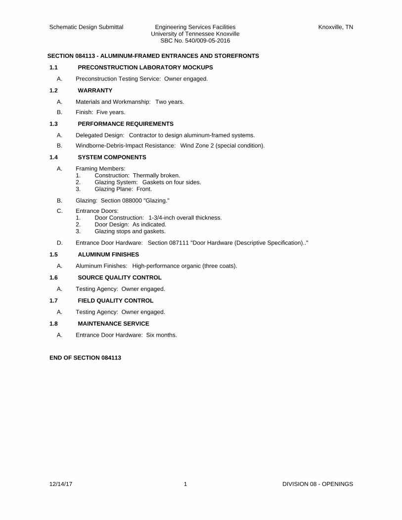
Schematic Design Submittal Engineering Services FacilitiesUniversity of Tennessee Knoxville
SBC No. 540/009-05-2016
Knoxville, TN
SECTION 084113 - ALUMINUM-FRAMED ENTRANCES AND STOREFRONTS
1.1 PRECONSTRUCTION LABORATORY MOCKUPS
A. Preconstruction Testing Service: Owner engaged.
1.2 WARRANTY
A. Materials and Workmanship: Two years.
B. Finish: Five years.
1.3 PERFORMANCE REQUIREMENTS
A. Delegated Design: Contractor to design aluminum-framed systems.
B. Windborne-Debris-Impact Resistance: Wind Zone 2 (special condition).
1.4 SYSTEM COMPONENTS
A. Framing Members:1. Construction: Thermally broken.2. Glazing System: Gaskets on four sides.3. Glazing Plane: Front.
B. Glazing: Section 088000 "Glazing."
C. Entrance Doors:1. Door Construction: 1-3/4-inch overall thickness.2. Door Design: As indicated.3. Glazing stops and gaskets.
D. Entrance Door Hardware: Section 087111 "Door Hardware (Descriptive Specification).."
1.5 ALUMINUM FINISHES
A. Aluminum Finishes: High-performance organic (three coats).
1.6 SOURCE QUALITY CONTROL
A. Testing Agency: Owner engaged.
1.7 FIELD QUALITY CONTROL
A. Testing Agency: Owner engaged.
1.8 MAINTENANCE SERVICE
A. Entrance Door Hardware: Six months.
END OF SECTION 084113
12/14/17 1 DIVISION 08 - OPENINGS

Schematic Design Submittal Engineering Services FacilitiesUniversity of Tennessee Knoxville
SBC No. 540/009-05-2016
Knoxville, TN
SECTION 084413 - GLAZED ALUMINUM CURTAIN WALLS
1.1 PRECONSTRUCTION LABORATORY MOCKUPS
A. Preconstruction Testing Service: Owner engaged.
1.2 WARRANTY
A. Materials and Workmanship: Two years.
B. Finish: 20 years.
1.3 PERFORMANCE REQUIREMENTS
A. Delegated Design: Contractor to design glazed aluminum curtain walls.
B. Windborne-Debris-Impact Resistance: Wind Zone 2 (special condition).
1.4 SYSTEM COMPONENTS
A. Framing Members:1. Construction: Thermally broken.2. Glazing System: Gaskets on four sides.3. Glazing Plane: Front.
B. Glazing: Section 088000 "Glazing."
1.5 ALUMINUM FINISHES
A. Aluminum Finishes: High-performance organic (three coats).
1.6 SOURCE QUALITY CONTROL
A. Testing Agency: Owner engaged.
1.7 FIELD QUALITY CONTROL
A. Testing Agency: Owner engaged.
END OF SECTION 084413
12/14/17 1 DIVISION 08 - OPENINGS

Schematic Design Submittal Engineering Services FacilitiesUniversity of Tennessee Knoxville
SBC No. 540/009-05-2016
Knoxville, TN
SECTION 087111 - DOOR HARDWARE (DESCRIPTIVE SPECIFICATION)
1.1 WARRANTY
A. Materials and Workmanship: Three years.
1.2 PRODUCTS
A. Provide all hardware specified or required to make doors fully functional, compliant with applicable codes, university campus standards, and secure to the extent indicated.
B. Provide products that comply with the following:1. Applicable provisions of federal, state, and local codes.2. Fire Rated Doors: NFPA 803. University campus standards
1.3 MAINTENANCE SERVICE
A. Full-Maintenance Service: 12 months.
1.4 FIELD QUALITY CONTROL
A. Independent Architectural Hardware Consultant: Owner engaged.
B. Occupancy Adjustment: After three months.
END OF SECTION 087111
12/14/17 1 DIVISION 08 - OPENINGS

Schematic Design Submittal Engineering Services FacilitiesUniversity of Tennessee Knoxville
SBC No. 540/009-05-2016
Knoxville, TN
SECTION 087113 - AUTOMATIC DOOR OPERATORS
1.1 PRODUCTS
A. Power Door Operators: Surface mounted.1. Standard: BHMA A156.10.2. Operation: Power opening and power-assisted spring closing.3. Operating System: Electromechanical.4. Microprocessor control unit.5. Finish: Matching door and frame.
B. Controls:1. Push-plate switch.2. Key switch.
C. Accessories:1. Signage.
1.2 MAINTENANCE SERVICE
A. Full-Maintenance Service: 12 months.
END OF SECTION 087113
12/14/17 1 DIVISION 08 - OPENINGS

Schematic Design Submittal Engineering Services FacilitiesUniversity of Tennessee Knoxville
SBC No. 540/009-05-2016
Knoxville, TN
SECTION 088000 - GLAZING
1.1 SUMMARY
A. Glass for windows, doors, interior borrowed lites, storefront framing, and glazed curtain walls.
B. Refer to section 134900 "Radiation Protection" for x-ray and radiation protection requirements.
1.2 QUALITY ASSURANCE
A. Mockups for aluminum-framed entrances and storefronts, aluminum windows, and glazed aluminum curtain walls.
1.3 WARRANTY
A. Laminated Glass: Five years.
B. Insulating Glass: 10 years.
1.4 PERFORMANCE REQUIREMENTS
A. Engineering design of glass by Contractor.
B. Windborne-Debris-Impact Resistance of Exterior Glazing: Wind Zone 2 (special conditions).
1.5 MATERIALS
A. Silicone Glazing Sealants: Neutral curing, Class 25.
B. Glazing Tapes: Back-bedding-mastic type.
1.6 MONOLITHIC GLASS SCHEDULE
A. Glass Type:Clear annealed float glass.
B. Glass Type:Clear heat-strengthened float glass.
C. Glass Type:Tinted heat-strengthened float glass.
1.7 LAMINATED GLASS SCHEDULE
A. Glass Type:Clear laminated glass; heat-strengthened float glass.
1.8 INSULATING GLASS SCHEDULE
A. Glass Type:Low-E-coated, clear insulating glass.1. Outdoor Lite: Annealed Fully tempered Ultraclear annealed Ultraclear heat-strengthened Ultraclear
fully tempered float glass.2. Indoor Lite: Fully tempered float glass.3. Interspace: Argon4. Low-E Basis of Design: Vitro (PPG Solar Ban 80)
B. Glass Type:(Campus standard)Low-E-coated, tinted insulating glass.1. Outdoor Lite: Tinted heat-strengthened float glass.2. Indoor Lite: Clear annealed heat-strengthened float glass.3. Interspace: Argon
END OF SECTION 088000
12/14/17 1 DIVISION 08 - OPENINGS

Schematic Design Submittal Engineering Services FacilitiesUniversity of Tennessee Knoxville
SBC No. 540/009-05-2016
Knoxville, TN
SECTION 088300 - MIRRORS
1.1 WARRANTY
A. Warranty: Five years.
1.2 PRODUCTS
A. Glass Mirrors: ASTM C 1503; manufactured using copper-free, low-lead mirror coating process.
B. Annealed Monolithic Glass Mirrors: Mirror Glazing Quality, clear.1. Nominal Thickness: As indicated.
C. Film backing for safety mirrors.
D. Mirror Hardware: Mirror clips.
E. Mirror Edges: Flat polished.
END OF SECTION 088300
12/14/17 1 DIVISION 08 - OPENINGS

Schematic Design Submittal Engineering Services FacilitiesUniversity of Tennessee Knoxville
SBC No. 540/009-05-2016
Knoxville, TN
SECTION 088813 - FIRE-RESISTANT GLAZING
1.1 WARRANTY
A. Laminated Glass: Not less than five years.
B. Double Glazing Units with Clear Gel Fill: Not less than 10 years.
1.2 MATERIALS
A. Silicone Glazing Sealants: Neutral curing, Class 50.
B. Glazing Tapes: Back-bedding-mastic or Expanded-cellular type.
1.3 FIRE-PROTECTION-RATED GLAZING SCHEDULE
A. Glass Type : 90-minute fire-protection-rated glazing with 450 deg F temperature-rise limitation; laminated glass with intumescent interlayers or double glazing units with clear gel fill.
END OF SECTION 088813
12/14/17 1 DIVISION 08 - OPENINGS

Schematic Design Submittal Engineering Services FacilitiesUniversity of Tennessee Knoxville
SBC No. 540/009-05-2016
Knoxville, TN
SECTION 089119 - FIXED LOUVERS
1.1 PERFORMANCE REQUIREMENTS
A. Structural Performance: Contractor to design louvers.
B. Wind Loads: Indicated on Drawings.
C. Seismic Performance:1. Design earthquake spectral response acceleration, short period (Sds) for Project is indicated on
Drawings.2. Component Importance Factor is indicated on Drawings.
D. Windborne-Debris-Impact Resistance: Louvers located within 30 feet of grade pass basic protection, when tested according to AMCA 540.
1.2 PRODUCTS
A. Operable louvers linked to the mechancial systems are located and described in Division 23 (HVAC).
B. Fixed Extruded-Aluminum Louvers:1. Horizontal Drainable-Blade Louver: 4 inches deep with exposed mullions.
C. Louver Screens:1. Provided at each exterior louver.2. Screening Type: Bird screening, except where insect screening is indicated.
D. Blank-Off Panels: Uninsulated.
E. Finishes:1. Aluminum: Two-coat fluoropolymer.
END OF SECTION 089119
12/14/17 1 DIVISION 08 - OPENINGS

Schematic Design Submittal Engineering Services FacilitiesUniversity of Tennessee Knoxville
SBC No. 540/009-05-2016
Knoxville, TN
SECTION 092116.23 - GYPSUM BOARD SHAFT WALL ASSEMBLIES
1.1 GYPSUM BOARD SHAFT WALL ASSEMBLIES
A. Fire-Resistance Rating: As indicated.
B. STC Rating: 51, minimum.
C. Gypsum shaftliner board, moisture- and mold-resistant, Type X.
D. Non-load-bearing steel framing in manufacturer's standard profiles.1. Firestop tracks to allow movement.
E. Finish Panels: Gypsum board.
F. Sound attenuation blankets.
1.2 AUXILIARY MATERIALS
A. Trim accessories.
B. Steel drill screws.
C. Track fasteners.
D. Reinforcing.
E. Acoustical sealant.
F. Gypsum board cants.
END OF SECTION 092116.23
12/14/17 1 DIVISION 09 - FINISHES

Schematic Design Submittal Engineering Services FacilitiesUniversity of Tennessee Knoxville
SBC No. 540/009-05-2016
Knoxville, TN
SECTION 092216 - NON-STRUCTURAL METAL FRAMING
1.1 QUALITY ASSURANCE
A. Code-compliance certification of studs and tracks.
1.2 MATERIALS
A. Steel Framing:1. Steel studs and tracks.2. Embossed steel studs and tracks.3. Slip-Type Head Joints:
a. Single long-leg track.b. Double tracks.c. Deflection track.
4. Firestop track.5. Flat strap and backing plate.6. Cold-rolled channel bridging.7. Hat-shaped, rigid furring channels.8. Resilient furring channels.9. Cold-rolled furring channels.10. Z-shaped furring.
B. Suspension Systems:1. Wire hangers.2. Flat hangers.3. Carrying channels (main runners).4. Furring channels.5. Grid suspension systems for ceilings.
END OF SECTION 092216
12/14/17 1 DIVISION 09 - FINISHES

Schematic Design Submittal Engineering Services FacilitiesUniversity of Tennessee Knoxville
SBC No. 540/009-05-2016
Knoxville, TN
SECTION 092900 - GYPSUM BOARD
1.1 QUALITY ASSURANCE
A. Mockups for the following:1. Levels of exposed gypsum board finish.
1.2 MATERIALS
A. Interior Gypsum Board:1. Gypsum board, Type X.2. Flexible gypsum board.3. Gypsum ceiling board.4. Impact-resistant gypsum board. (Level 3)5. Mold-resistant gypsum board.
B. Exterior Gypsum Board for Ceilings and Soffits:1. Glass-mat gypsum sheathing board.
C. Tile-Backing Panels:1. Cementitious backer units.
D. Trim Accessories:1. Interior.2. Exterior.3. Aluminum: Extruded profiles.
E. Auxiliary Materials:1. Acoustical Sealant.
END OF SECTION 092900
12/14/17 1 DIVISION 09 - FINISHES

Schematic Design Submittal Engineering Services FacilitiesUniversity of Tennessee Knoxville
SBC No. 540/009-05-2016
Knoxville, TN
SECTION 093013 - CERAMIC TILING
1.1 QUALITY ASSURANCE
A. Mockup for each type of floor tile installation.
B. Mockup for wall tile installation.
1.2 TILE PRODUCTS
A. Tile Type : Glazed ceramic mosaic tile.1. Composition: Vitreous or impervious natural clay or porcelain.2. Trim Shapes: Base cove, Bead (bullnose) external corner, Coved internal corner, and Tapered
transition.
B. Tile Type : Glazed porcelain tile.1. Face Size Variation: Rectified.2. Trim Shapes: Base cove, Bead (bullnose) external corner, Coved internal corner, and Tapered
transition.
C. Tile Type : Glazed wall tile.1. Face Size Variation: Rectified.2. Trim Shapes: Coved base, Bullnose wainscot cap, and Bullnose external corner.
1.3 ACCESSORY MATERIALS
A. Thresholds: Marble.
B. Tile Backing Panels: Cementitious backer units.
C. Waterproof Membrane: Chlorinated polyethylene sheet, PVC sheet, Polyethylene sheet, or Fabric-reinforced, modified-bituminous sheet.
D. Crack Isolation Membrane: Chlorinated polyethylene sheet, PVC sheet, Polyethylene sheet, Corrugated polyethylene, or Fabric-reinforced, modified-bituminous sheet.
E. Metal edge strips.
1.4 INTERIOR TILE INSTALLATION SCHEDULE
A. Interior Floors on Concrete:1. TCNA F112: Cement mortar bed bonded to concrete. High-performance grout.2. TCNA F121: Cement mortar bed on waterproof membrane. High-performance grout.3. TCNA F122: Thinset mortar on waterproof membrane. High-performance grout.4. TCNA F125A: Thinset mortar on crack isolation membrane. Water-cleanable epoxy grout.
B. Interior Walls, Wood or Metal Studs or Furring:1. TCNA W244: Thinset mortar on cementitious backer units or fiber-cement underlayment[ over
vapor-retarder membrane]. Water-cleanable epoxy grout.
END OF SECTION 093013
12/14/17 1 DIVISION 09 - FINISHES

Schematic Design Submittal Engineering Services FacilitiesUniversity of Tennessee Knoxville
SBC No. 540/009-05-2016
Knoxville, TN
SECTION 095113 - ACOUSTICAL PANEL CEILINGS
1.1 QUALITY ASSURANCE
A. Mockups for each form of construction.
1.2 PERFORMANCE REQUIREMENTS
A. Engineering design of seismic restraints by Contractor.
B. Flame-Spread Index: Class A.
C. Smoke-Developed Index: 50.
1.3 PRODUCTS
A. Acoustical Panels: Fire-Resistance Rated: .1. Type III: Mineral base with painted finish.2. Type IV: Mineral base with vinyl face, back, and sealed edges.3. Pattern: To be indicated on the Finish Schedule on the drawings..4. Thickness: 3/4 inch .5. Modular Size: 24 by 24 inches , 24 by 48 inches , or 24 by 96 inches as indicated on the
Finish Schedule on the Drawings..
B. Metal Suspension System: .1. Wide-Face, Capped, Double-Web, Fire-Rated Steel: Intermediate Heavy duty.2. Narrow-Face, Capped, Double-Web Steel: Intermediate duty.3. Narrow-Face, Steel-Capped, Double-Web, Fire-Rated Steel: Intermediate duty.4. Wide-Face, Single-Web Steel: Heavy duty.5. Narrow-Face, Single-Web, Extruded Aluminum: Intermediate duty.6. Attachment Devices: Cast in place or power actuated.7. Hold-down clips.
C. Metal Edge Moldings and Trim: Roll-formed sheet metal or Extruded aluminum.
1.4 ERECTION TOLERANCES
A. Main and Cross Runners: Level to within 1/8 inch in 12 feet.
B. Moldings and Trim: Level to within 1/8 inch in 12 feet.
1.5 FIELD QUALITY CONTROL
A. Special Inspection: Owner -engaged special inspector for seismic design.
B. Testing Agency: Owner engaged.
END OF SECTION 095113
12/14/17 1 DIVISION 09 - FINISHES

Schematic Design Submittal Engineering Services FacilitiesUniversity of Tennessee Knoxville
SBC No. 540/009-05-2016
Knoxville, TN
SECTION 096513 - RESILIENT BASE AND ACCESSORIES
1.1 PRODUCTS
A. Resilient Base: Thermoset rubber.1. Style and Location:
a. Straight: In areas with carpet.b. Cove: In areas with resilient flooring.
2. Minimum Thickness: 0.125 inch.3. Height: 4 inches.4. Outside Corners: Preformed.5. Inside Corners: Job formed or preformed.
B. Installation Materials:1. Trowelable leveling and patching compounds.2. Adhesives.3. Stair-tread-nose filler.4. Metal edge strips.5. Floor polish.
END OF SECTION 096513
12/14/17 1 DIVISION 09 - FINISHES

Schematic Design Submittal Engineering Services FacilitiesUniversity of Tennessee Knoxville
SBC No. 540/009-05-2016
Knoxville, TN
SECTION 096516 - RESILIENT SHEET FLOORING
1.1 PRODUCTS
A. Vinyl Sheet Flooring:1. Backing: None, unbacked.2. Wearing Surface: Smooth.3. Seamless-Installation Method: Heat welded.
B. Installation Materials:1. Trowelable leveling and patching compounds.2. Adhesives.3. Floor polish.
END OF SECTION 096516
12/14/17 1 DIVISION 09 - FINISHES

Schematic Design Submittal Engineering Services FacilitiesUniversity of Tennessee Knoxville
SBC No. 540/009-05-2016
Knoxville, TN
SECTION 096516.13 - LINOLEUM FLOORING
1.1 PRODUCTS
A. General:1. Linoleum complies with FloorScore Standard.
B. Linoleum Floor Coverings:1. Floor Tile: Manufacturer's standard.2. Sheet Flooring: In manufacturer's standard length by not less than 78 inches wide.3. Seaming Method: Heat welded.4. Thickness: 0.10 inch.
C. Installation Materials:1. Trowelable leveling and patching compounds.2. Adhesives.3. Heat welding bead.4. Integral-flash-cove-base accessories.5. Floor polish.
1.2 INSTALLATION
A. Sheet Flooring Layout:1. Integral-Flash-Cove Base: Cove floor coverings dimension indicated up vertical surfaces.
END OF SECTION 096516.13
12/14/17 1 DIVISION 09 - FINISHES

Schematic Design Submittal Engineering Services FacilitiesUniversity of Tennessee Knoxville
SBC No. 540/009-05-2016
Knoxville, TN
SECTION 096536 - STATIC-CONTROL RESILIENT FLOORING
1.1 PERFORMANCE REQUIREMENTS
A. Static-Dissipative Properties:1. Electrical Resistance: Test per ASTM F 150 with 100-V applied voltage or ESD-STM-7.1.2. Static Generation: Less than 300 V.3. Static Decay: 5000 to zero V in less than 0.25 seconds.
1.2 PRODUCTS
A. Static-Dissipative Resilient Floor Coverings:1. Solid Vinyl Floor Tile: 24 by 24 inches.
B. Installation Materials:1. Trowelable leveling and patching compounds.2. Grounding strips.3. Heat-welding bead.4. Integral-flash-cove base accessories.
1.3 INSTALLATION
A. Installation with oversight by manufacturer's representative.
B. Seaming Method: Heat welded.
C. Integral-Flash-Cove Base: Dimension indicated.
1.4 FIELD QUALITY CONTROL
A. Testing Agency: Owner engaged.
END OF SECTION 096536
12/14/17 1 DIVISION 09 - FINISHES

Schematic Design Submittal Engineering Services FacilitiesUniversity of Tennessee Knoxville
SBC No. 540/009-05-2016
Knoxville, TN
SECTION 096723 - RESINOUS FLOORING
1.1 QUALITY ASSURANCE
A. Mockups: For each resinous flooring system.
1.2 PRODUCTS
A. Resinous Flooring and Integral Cove Base:1. System Characteristics:
a. Color and Pattern: As selected by Architect from manufacturer's full range.b. Wearing Surface: Manufacturer's standard wearing surface.c. Overall System Thickness: 3/16 inch.
2. System Components:a. Primer: 100 percent solids.b. Waterproofing Membrane: 100 percent solids.c. Reinforcing Membrane[ with Fiberglass Scrim]: 100 percent solids.d. Body Coat(s):
1) Resin: Epoxy .2) Formulation Description: 100 percent solids.3) Application Method: Self-leveling slurry.4) Number of Coats: Two.5) Thickness of Coats: 8 mils.
e. Grout Coat:1) Resin: Epoxy .2) Formulation Description: 100 percent solids.3) Thickness of Coat: 8 mils.
f. Topcoat: Sealing or finish coats.1) Resin: Epoxy .2) Formulation Description: 100 percent solids.3) Number of Coats: One.4) Thickness of Coats: 8 mils.5) Finish: Gloss.
3. System Chemical Resistance: Tested according to ASTM D 1308 for 50 percent immersion, ASTM D 543, Procedure A, for immersion, or ASTM C 267 for immersion in the following reagents for no fewer than seven days:
1.3 FIELD QUALITY CONTROL
A. Core sampling by Contractor.
END OF SECTION 096723
12/14/17 1 DIVISION 09 - FINISHES

Schematic Design Submittal Engineering Services FacilitiesUniversity of Tennessee Knoxville
SBC No. 540/009-05-2016
Knoxville, TN
SECTION 096813 - TILE CARPETING
1.1 QUALITY ASSURANCE
A. Mockups for each type of carpet tile installation.
1.2 WARRANTY
A. Materials and Workmanship for Carpet Tile: 10 years.
1.3 PRODUCTS
A. Carpet Tile :1. Fiber: 100 percent nylon 6 .2. Pile Characteristic: Level-loop pile.3. Size: 24 by 24 inches .4. Applied Treatments: Soil resistant and Antimicrobial.
END OF SECTION 096813
12/14/17 1 DIVISION 09 - FINISHES

Schematic Design Submittal Engineering Services FacilitiesUniversity of Tennessee Knoxville
SBC No. 540/009-05-2016
Knoxville, TN
SECTION 099113 - EXTERIOR PAINTING
1.1 PAINT, GENERAL
A. MPI-listed products.
1.2 SOURCE QUALITY CONTROL
A. Testing Agency: Owner engaged.
1.3 EXTERIOR PAINTING SCHEDULE
A. Steel and Iron Substrates:1. Water-based light industrial coating system.
B. Galvanized-Metal Substrates:1. Latex system.
C. Exterior Gypsum Board Substrates:1. Latex system.
END OF SECTION 099113
12/14/17 1 DIVISION 09 - FINISHES

Schematic Design Submittal Engineering Services FacilitiesUniversity of Tennessee Knoxville
SBC No. 540/009-05-2016
Knoxville, TN
SECTION 099123 - INTERIOR PAINTING
1.1 PAINT, GENERAL
A. MPI-listed products.
1.2 SOURCE QUALITY CONTROL
A. Testing: Owner engaged.
1.3 INTERIOR PAINTING SCHEDULE
A. Concrete Substrates, Nontraffic Surfaces:1. Institutional low-odor/VOC latex system.
B. Steel Substrates:1. Water-based dry-fall over shop-applied quick-drying shop primer system.
C. Galvanized-Metal Substrates:1. Institutional low-odor/VOC latex system.2. Alkyd dry-fall system (cementitious primer).
D. Gypsum Board Substrates:1. Institutional low-odor/VOC latex system.
END OF SECTION 099123
12/14/17 1 DIVISION 09 - FINISHES

Schematic Design Submittal Engineering Services FacilitiesUniversity of Tennessee Knoxville
SBC No. 540/009-05-2016
Knoxville, TN
SECTION 099600 - HIGH-PERFORMANCE COATINGS
1.1 MATERIALS, GENERAL
A. MPI-listed products.
1.2 SOURCE QUALITY CONTROL
A. Testing: Owner engaged.
1.3 INTERIOR HIGH-PERFORMANCE COATING SCHEDULE
A. Steel Substrates:1. Metal doors and frames: Epoxy, high-build system.2. Steel railing systems: Pigmented polyurethane over self-priming epoxy system.
B. Gypsum Board Substrates:1. Epoxy system.
END OF SECTION 099600
12/14/17 1 DIVISION 09 - FINISHES

Schematic Design Submittal Engineering Services FacilitiesUniversity of Tennessee Knoxville
SBC No. 540/009-05-2016
Knoxville, TN
SECTION 101100 - VISUAL DISPLAY UNITS
1.1 QUALITY ASSURANCE
A. Mockups for each form of construction.
1.2 WARRANTY
A. Materials and Workmanship for Porcelain-Enamel Face Sheets: Life of building.
1.3 PRODUCTS
A. Visual Display Board Assembly: Markerboard, Tackboard, and Combination panels.1. Assembly: Field or factory.2. Frames and Trim: Factory-applied aluminum.3. Mounting: Direct to wall.
1.4 MATERIALS
A. Visual Display Panels:1. Markerboard Panel: Faced with porcelain enamel.2. Tackboard Panel: Faced with natural cork.
B. Aluminum Finishes: Baked enamel or powder coat.
END OF SECTION 101100
12/14/17 1 DIVISION 10 - SPECIALTIES

Schematic Design Submittal Engineering Services FacilitiesUniversity of Tennessee Knoxville
SBC No. 540/009-05-2016
Knoxville, TN
SECTION 101423 - PANEL SIGNAGE
1.1 PANEL SIGNS
A. Panel Sign : Sign with exposed edges.1. Engraved Plastic-Laminate Sign: Graphics engraved through plastic-laminate face sheet to expose
contrasting phenolic core.a. Comply with UT Campus standard.
1) Graphics: Gotham2. Mounting: Surface mounted with concealed anchors .
END OF SECTION 101423
12/14/17 1 DIVISION 10 - SPECIALTIES

Schematic Design Submittal Engineering Services FacilitiesUniversity of Tennessee Knoxville
SBC No. 540/009-05-2016
Knoxville, TN
SECTION 102113.14 - STAINLESS-STEEL TOILET COMPARTMENTS
1.1 SUMMARY
A. Stainless-steel toilet compartments configured as toilet enclosures and urinal screens.1. Toilet-Enclosure Style: Floor and ceiling anchored.2. Urinal-Screen Style: Wall hung, flat panel .
1.2 PERFORMANCE REQUIREMENTS
A. Regulatory Requirements: Comply with applicable provisions in U.S. Architectural & Transportation Barriers Compliance Board's ADA-ABA Accessibility Guidelines for Buildings and Facilities and ICC A117.1 for toilet compartments designated as accessible.
1.3 COMPONENTS
A. Door, Panel, and Pilaster Construction: No-sightline system.
B. Urinal-Screen Post: Match pilasters.
C. Brackets (Fittings):1. Full-Height (Continuous) Type: Manufacturer's standard design; stainless steel aluminum.
D. Stainless-Steel Finish: Manufacturer's standard textured finish.
1.4 HARDWARE AND ACCESSORIES
A. Hardware and Accessories: Manufacturer's heavy-duty stainless-steel operating hardware and accessories.
END OF SECTION 102113.14
12/14/17 1 DIVISION 10 - SPECIALTIES

Schematic Design Submittal Engineering Services FacilitiesUniversity of Tennessee Knoxville
SBC No. 540/009-05-2016
Knoxville, TN
SECTION 102239 - FOLDING PANEL PARTITIONS
1.1 WARRANTY
A. Materials and Workmanship: Two years.
1.2 PERFORMANCE REQUIREMENTS
A. Delegated Design: Seismic bracing of tracks to structure above.
B. Seismic Performance: According to ASCE/SEI 7.
C. Flame-Spread Index: 25 or less.
1.3 OPERABLE ACOUSTICAL PANELS
A. Panel Operation: Manually operated, paired panels.
B. Panel Width: Equal widths.
C. STC: Not less than 41.
D. Panel Weight: 10 lb/sq. ft. maximum.
E. Panel Thickness: Nominal dimension of 4 inches.
F. Panel Materials:1. Frame: Steel.2. Face/Liner Sheets: Steel.3. Core and Facings: Gypsum board.
G. Hardware: Manufacturer's standard hinges.
H. Finish Facing: Paint.
1.4 FIELD QUALITY CONTROL
A. NIC Testing: By Owner -engaged agency.
1.5 MAINTENANCE SERVICE
A. Full-Maintenance Service: 12 months.
END OF SECTION 102239
12/14/17 1 DIVISION 10 - SPECIALTIES

Schematic Design Submittal Engineering Services FacilitiesUniversity of Tennessee Knoxville
SBC No. 540/009-05-2016
Knoxville, TN
SECTION 102600 - WALL AND DOOR PROTECTION
1.1 PERFORMANCE REQUIREMENTS
A. Structural Performance: Handrails to resist uniform load of 50 lbf/ft. and concentrated load of 200 lbf, not applied concurrently.
1.2 WARRANTY
A. Materials and Workmanship: Five years.
1.3 PRODUCTS
A. Wall Bumper Rails:1. Aluminum Bumper Rails: 1/4 inch x 4 inch 6061-T6511 extruded aluminum bar with 1/8 inch radius
a. Brackets: extruded aluminumb. Hardware: stainless steelc. Finish: Clear anodized type II
END OF SECTION 102600
12/14/17 1 DIVISION 10 - SPECIALTIES

Schematic Design Submittal Engineering Services FacilitiesUniversity of Tennessee Knoxville
SBC No. 540/009-05-2016
Knoxville, TN
SECTION 102800 - TOILET, BATH, AND LAUNDRY ACCESSORIES
1.1 WARRANTY
A. Silver Spoilage for Mirrors: 15 years.
1.2 PRODUCTS
A. Public-Use Washroom Accessories:1. Toilet tissue (roll) dispenser.2. Paper towel (folded) dispenser.3. Combination towel (folded) dispenser/waste receptacle.4. Liquid-soap dispenser.5. Grab bar.6. Sanitary -napkin dispenser.7. Sanitary-napkin disposal unit.8. Framed Mirror unit.9. Robe hook.
B. Warm-Air Dryers:1. Warm-air dryer.
C. Childcare Accessories:1. Diaper-changing station.
D. Underlavatory guards.
E. Custodial Accessories:1. Mop and broom holder.
END OF SECTION 102800
12/14/17 1 DIVISION 10 - SPECIALTIES

Schematic Design Submittal Engineering Services FacilitiesUniversity of Tennessee Knoxville
SBC No. 540/009-05-2016
Knoxville, TN
SECTION 104413 - FIRE PROTECTION CABINETS
1.1 PRODUCTS
A. Fire-Protection Cabinets:1. Type: Fire extinguisher .2. Cabinet Construction: Nonrated.3. Mounting: Semirecessed.4. Door Style: Center glass panel with frame.5. Door Glazing: Acrylic sheet.6. Finish:
a. Steel: Factory primed for field painting.
END OF SECTION 104413
12/14/17 1 DIVISION 10 - SPECIALTIES

Schematic Design Submittal Engineering Services FacilitiesUniversity of Tennessee Knoxville
SBC No. 540/009-05-2016
Knoxville, TN
SECTION 104416 - FIRE EXTINGUISHERS
1.1 WARRANTY
A. Materials and Workmanship: Six years.
1.2 PERFORMANCE REQUIREMENTS
A. Fire Extinguishers: Complying with NFPA 10 and approved, listed, and labeled by FM Global.
1.3 PRODUCTS
A. Portable Hand-Carried Fire Extinguishers:1. Multipurpose dry-chemical type.
a. 10 pound; A:B:C
B. Mounting brackets.
END OF SECTION 104416
12/14/17 1 DIVISION 10 - SPECIALTIES
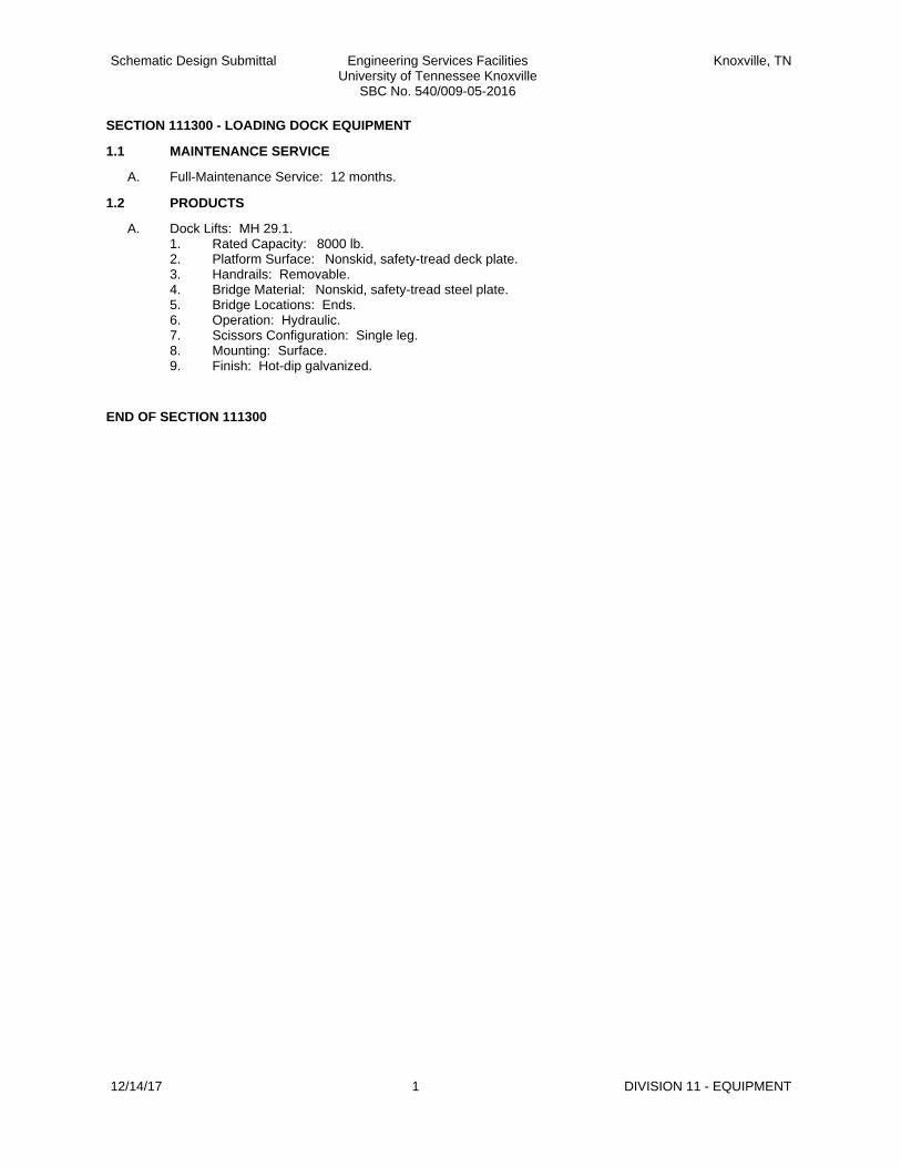
Schematic Design Submittal Engineering Services FacilitiesUniversity of Tennessee Knoxville
SBC No. 540/009-05-2016
Knoxville, TN
SECTION 111300 - LOADING DOCK EQUIPMENT
1.1 MAINTENANCE SERVICE
A. Full-Maintenance Service: 12 months.
1.2 PRODUCTS
A. Dock Lifts: MH 29.1.1. Rated Capacity: 8000 lb.2. Platform Surface: Nonskid, safety-tread deck plate.3. Handrails: Removable.4. Bridge Material: Nonskid, safety-tread steel plate.5. Bridge Locations: Ends.6. Operation: Hydraulic.7. Scissors Configuration: Single leg.8. Mounting: Surface.9. Finish: Hot-dip galvanized.
END OF SECTION 111300
12/14/17 1 DIVISION 11 - EQUIPMENT

Schematic Design Submittal Engineering Services FacilitiesUniversity of Tennessee Knoxville
SBC No. 540/009-05-2016
Knoxville, TN
SECTION 122113 - HORIZONTAL LOUVER BLINDS
1.1 QUALITY ASSURANCE
A. Mockups for each form of construction.
1.2 PRODUCTS
A. Horizontal Louver Blinds, Aluminum Slats:1. Slat Width: 2 inches .2. Perforated Slats: Openness factor of 6 to 7 percent.3. Operating Mechanisms: Manual.4. Tilt: Full.5. Valance.6. Mounting: Wall.7. Side channels and perimeter light gap seals.
B. Installation: Between (inside) jamb.
1.3 DEMONSTRATION
A. Factory-authorized service representative to provide training services for adjusting, operating, and maintaining motorized systems.
END OF SECTION 122113
12/14/17 1 DIVISION 12 - FURNISHINGS

Schematic Design Submittal Engineering Services FacilitiesUniversity of Tennessee Knoxville
SBC No. 540/009-05-2016
Knoxville, TN
SECTION 122413 - ROLLER WINDOW SHADES
1.1 PRODUCTS
A. Motorized operating mechanism.
B. Roller Mounting Configuration: Single roller and Double roller, side by side.
C. Installation Accessories: Front fascia Recessed shade pocket Side channels and bottom (sill) channel or angle.
D. Shadeband Materials: Complying with NFPA 701.1. Light-Filtering Fabric: Acrylic-coated fiberglass.2. Light-Blocking Fabric: Acrylic-coated fiberglass .
E. Product Safety Standard: WCMA A 100.1.
1.2 INSTALLATION
A. Between (inside) jamb installation.
B. Factory-authorized representative to train Owner's personnel to maintain motorized operators.
END OF SECTION 122413
12/14/17 1 DIVISION 12 - FURNISHINGS

Schematic Design Submittal Engineering Services FacilitiesUniversity of Tennessee Knoxville
SBC No. 540/009-05-2016
Knoxville, TN
SECTION 124816 - ENTRANCE FLOOR GRILLES
1.1 COMPONENTS
A. Stainless-Steel Foot Grilles:1. Grating: Pit type.2. Finish: No. 4.
B. Frame: Same material and finish as foot grille.
C. Support System: Extruded-metal support system for drainage pitapplications.
END OF SECTION 124816
12/14/17 1 DIVISION 12 - FURNISHINGS

Schematic Design Submittal Engineering Services FacilitiesUniversity of Tennessee Knoxville
SBC No. 540/009-05-2016
Knoxville, TN
SECTION 132113.33 - CLEANROOM WALL SYSTEM (CRPS)
PART 1 - GENERAL
1.1 SUMMARY
A. Section Includes:1. The General Contractor Provides: This Section specifies the requirements necessary to furnish and
install cleanroom wall system including, but not necessarily limited to:a. Metal framing system, including all items such as studs, door frames, deflection heads,
clips, anchors, screws, attachments, and supports, etc., which will provide a complete self-supporting assembly for the cleanroom wall system.
b. Cleanroom wall panel material, including paint, coating, or finish.c. Reinforcing, bracing, blocking, trim finishing strips, and non-outgassing type gaskets
necessary to maintain the structural and air sealing requirements of the assembly.d. Lateral bracing of all portions of the support system.e. A complete self-furred cleanroom wall system for application on gypsum board or concrete
masonry wall.f. Cleaning prior to, during, and after wall system installation for cleanroom contamination
control.g. Engineering of wall system to meet design criteria.h. Furnish and install complete manual cleanroom doors, including pivots, hardware, closer
and door stops.
1.2 CLEANROOM WALL SYSTEM
A. The cleanroom wall and cleanroom wall furring systems design shall require no cutting, drilling, or chipping in the cleanroom during assembly. The wall systems shall have the capability to be finished flush on one or both sides, and minimize the need for field cutting. Mitering components in the cleanroom will not be allowed.
B. Sealants and Gaskets: Use sealants and gaskets in the fabrication, assembly and installation of the work, which are recommended and guaranteed by the manufacturer to remain permanently elastic, non-shrinking, non-migrating, and without effect of outgassing.
END OF SECTION
12/14/17 1 DIVISION 13 - SPECIAL CONSTRUCTION

Schematic Design Submittal Engineering Services FacilitiesUniversity of Tennessee Knoxville
SBC No. 540/009-05-2016
Knoxville, TN
SECTION 132700 - VAULTS
1.1 PERFORMANCE REQUIREMENTS
A. Engineering design of modular vaults by Contractor.
1.2 PRODUCTS
A. Radiation Resistance Modular Vaults: Coordinate resistance rating with nuclear report.
B. Fire-Resistance-Rated Modular Vaults: Class 350 - 4 Hour including:1. Vault panels.2. Vault Door Assembly: One -door assembly.
1.3 FIELD QUALITY CONTROL
A. Manufacturer's field service to test and inspect vaults.
END OF SECTION 132700
12/14/17 1 DIVISION 13 - SPECIAL CONSTRUCTION

Schematic Design Submittal Engineering Services FacilitiesUniversity of Tennessee Knoxville
SBC No. 540/009-05-2016
Knoxville, TN
SECTION 134900 - RADIATION PROTECTION
1.1 MATERIALS
A. Lead sheet, strip, and plate.
B. Lead-lined concrete masonry units.
C. Lead-Lined Gypsum Board: 5/8 inchthick.
D. Lead Glass: Lead-barium, polished glass.1. Safety Glass: Laminated safety.
1.2 MANUFACTURED UNITS
A. Lead-Lined, Hollow-Metal Door Frames: NAAMM-HMMA 861 except 0.0667 inch thick; factory lined.
B. Lead-Lined Flush Wood Doors: With observation windows.1. Door Construction: Veneer face, bonded structural composite lumber or glued-wood-stave core.2. Grade: Custom.
C. Lead-lined modular shielding partitions.
D. Neutron-shielding doors, frames, and hardware.
E. Informational signs of engraved high-pressure laminate.
1.3 FIELD QUALITY CONTROL
A. Testing Agency: Owner engaged.
END OF SECTION 134900
12/14/17 1 DIVISION 13 - SPECIAL CONSTRUCTION

Schematic Design Submittal Engineering Services FacilitiesUniversity of Tennessee Knoxville
SBC No. 540/009-05-2016
Knoxville, TN
SECTION 142100 - ELECTRIC TRACTION ELEVATORS
1.1 SUMMARY
A. Passenger and service elevators.
1.2 ELEVATORS
A. Elevator Number(s): as indicated on Drawings.
B. Service Elevator Number(s): as indicated on Drawings.
C. Machine Location: Machine room above hoistway.
D. Machine Type: Geared and Gearless traction.
E. Rated Load: 1. Passenger: 3500 lb.2. Service: 5000 lb.
F. Rated Speed: 1. Passenger: 350 fpm.2. Service: 200 fpm
G. Operation System: Group automatic with demand-based dispatching.
H. Auxiliary Operations:1. Standby power operation Battery-powered automatic evacuation.2. Earthquake Emergency Operation: ASME A17.1/CSA B44.3. Automatic dispatching of loaded car.4. Nuisance-call cancel.5. Loaded-car bypass.6. Distributed parking.7. Off-peak operation.8. Automatic operation of lights and ventilation fans.9. Independent service for all cars in group.
I. Security Features: Car-to-lobby feature.
J. Car Enclosures: Steel framed with nonremovable wall panels and removable roof.1. Inside Height: 93 inches.2. Front Walls (Return Panels): Stainless steel.3. Side and Rear Wall Panels:
a. Passenger: b. Service: Textured stainless steel with pad pegs
4. Doors: Stainless steel .5. Door Sills: Aluminum.6. Ceiling: Stainless steel.7. Handrails: Stainless steel.8. Floor: Prepared to receive
a. Passenger: Porcelain tileb. Service: resilient flooring.
K. Hoistway Entrances:1. Height: 84 inches.2. Type: Single-speed center opening.
L. Hall Fixtures at First Floor: Stainless steel.
M. Hall Fixtures at Other Floors: Stainless steel.
1.3 TRACTION SYSTEMS
A. Passenger Elevator Machines: Either variable-voltage, variable-frequency ac or variable-voltage dc type; with solid-state power converters.
B. Regenerative or nonregenerative system.
C. Roller guides or polymer-coated, nonlubricated sliding guides.
12/14/17 1 DIVISION 14 - CONVEYING EQUIPMENT

Schematic Design Submittal Engineering Services FacilitiesUniversity of Tennessee Knoxville
SBC No. 540/009-05-2016
Knoxville, TN
1.4 SIGNAL EQUIPMENT
A. Car Control Stations: Semirecessed or recessed type.
B. Firefighters' two-way telephone communication service.
C. Fire-command-center annunciator panel.
1.5 MAINTENANCE SERVICE
A. Full-Maintenance Service: To be determined..
END OF SECTION 142100
12/14/17 2 DIVISION 14 - CONVEYING EQUIPMENT

Specification Section 27.13.13 12-14-17
Structured Cabling System
1. Outside plant/service entrance
a. Service entrance shall consist of a concrete encased duct bank originating in MH14,
traveling down the hill and entering the building on the 2nd level on the North side.
b. Entrance shall consist of one 36 strand single mode fiber optic cable and one 200pr
copper cable.
2. Infrastructure
a. Building shall be equipped with 18” basket type cable tray running along the walls of the
main corridors, above ceiling level.
b. Data outlets in the rooms shall have conduit that extends from the outlet and attaches
to the tray.
c. Floor penetration sleeves (4x4”) shall extend as a riser between Comm. Rooms.
d. Contractor is responsible for data racks, patch panels (fiber and copper), etc.
3. Cabling – Backbone
a. Shall consist of one 12 strand single mode, fiber optic cable extending from the main
Comm. Room, connecting to others.
4. Cabling – Horizontal
a. Shall consist of CAT6 cable extending from each data outlet to the nearest Comm. Room
(100-meter limit).
b. Data outlets in each room shall be served with 2 CAT6 cables.
c. Wireless access points shall be located as directed by the University and shall be served
by 2 CAT6 cables.
5. Cabling – Copper Riser
a. Shall consist of one 25pr ARMM from the main Communications room to each Comm.
Closet.
6. Electronics
a. All electronics, Wi-Fi access points (interior and exterior), data switches, UPS, etc. shall
be provided by the Owner.

Specification Section 27.41.00 12-14-17
Audio/Visual Systems
1. Provisions
a. Floor and wall boxes, power outlets, conduit, data outlets, standard cabling, screens,
ceiling speakers, etc shall be specified under the Construction documents and provided
as part of the base bid.
b. Electronics such as specialty cables (HDMI, RS232, etc) monitors, projectors, control
components, etc. shall be specified and installed by UTK. The Bid Documents shall
contain an allowance to fund this work.
c. Electronic signage video monitors shall be included in the elevator lobby of each floor
and at each main entrance.

Specification Section 27.53.13 12-14-17
Synchronized Clocks
1. Infrastructure
a. 120v receptacle to be provided at each clock location by the Electrical Contractor.
2. Provisions
a. All clocks shall be the campus standard “Primex” brand, size and quantity as shown on
the drawings.
b. All clocks shall receive a wireless sync signal from the transmitter at the Ayers Hall bell
tower.
c. Clocks shall be located in instructional areas such as teaching laboratories and
classrooms.

Specification Section 27.53.19 12-14-17
Distributed Antenna System
1. Provisions
a. System shall include a series of antennas located throughout the building and connected
by “Heliax” type coaxial cable.
b. Antenna locations shall be calculated by a dedicated computer RF design program.
c. System is based upon current 900mhz and future 800mhz systems.
d. System is designed for First Responders only. No provisions are included for cellular
phone services.
e. All equipment shall be compatible with and connected to the existing head-end
equipment located at the Student Union and shall be connected to same via a single
mode fiber optic cable provided by the University.

Specification Section 28.16.00 12-14-17
Access control/Intrusion Detection System
1. Control Platform/Existing Systems
a. The University has in place a Gallagher FT Command Center control system. All work and
provisions will be compatible with the existing system
b. All provisions for and connections and programming for the Gallagher system shall be by
a factory authorized dealer with certified technicians.
c. The University uses HID i-class cards for identification and access through controlled
doors. All such cards shall be provided and formatted by the Owner.
2. Provisions – Door Access and Monitoring
a. Exterior entrance doors shall be secured and controlled via the Gallagher system. Some
exit only doors may be monitored through a door position switch but will have no
features for outside access.
b. Lab entrance doors shall access controlled by the Gallagher system
c. Class room and lecture hall doors shall be equipped with electronic solenoid locks that
can be controlled by the room user or by UTPD for campus-wide lockdown features.
d. All Comm. Rooms shall be equipped with access controlled doors.
e. All elevators shall include a card reader for floor call control.
3. Provisions – Fire Alarm
a. The building fire alarm system shall be connected to the Gallagher system for
annunciation of alarm at the UTPD Dispatch Center.

Specification Section 28.23.00 12-14-17
CCTV System
1. Provisions
a. All equipment shall be the campus standard “Avigilon”
b. All cameras shall be network connected to the Owners data switches.
c. All cameras shall be 2mp (min.) digital cameras. No analog type cameras shall be used.
d. Contractor shall provide Network Video Recorders with sufficient memory to capture
and store video from all cameras for 30 days recording time.
e. Electrical Contactor shall supply back boxes and shall install conduit in areas that are not
served by cable tray.
2. Location
a. Outdoor PTZ cameras shall be located as directed by the Owner.
b. Indoor cameras shall be located at each building entrance and shall be aimed to obtain
clear facial shots of all that enter the building.
c. Cameras shall be located in the passenger elevator lobby of each floor.
d. Contractor shall extend data cable and provide rough-in for future use camera locations
as selected by the Owner.

Schematic Design Submittal Engineering Services FacilityUniversity of Tennessee Knoxville
SBC No. 540/009-05-2016
Knoxville, TN
12/14/17 1 DRILLED CONCRETE PIERS(CAISSONS)
SECTION 31.63.29
DRILLED CONCRETE PIERS (CAISSONS)
PART 1 GENERAL
1.01 REFERENCES
A. ACI 336.1 - Standard Specification for the Construction of Drilled Piers; American ConcreteInstitute International.
B. ASTM A 36/A 36M - Standard Specification for Carbon Structural Steel.
C. ASTM A 283/A 283M - Standard Specification for Low and Intermediate Tensile StrengthCarbon Steel Plates.
D. ASTM A 929/A 929M - Standard Specification for Steel Sheet, Metallic-Coated by the Hot-DipProcess for Corrugated Steel Pipe.
1.02 QUALITY ASSURANCE
A. Drilled pier Standard: Comply with provisions in ACI 336.1, "Reference Specifications for theConstruction of Drilled Piers," unless modified in this Section.
B. Drilled pier Contractor shall be qualified to install the type drilled pier specified in accordancewith Drawings, Specifications, local codes and regulations, and subsurface conditions existingat the site.
1. Minimum requirements for qualifications are 5 years of drilled pier experience andevidence of the satisfactory completion of 10 installations comparable in scope to that ofthis project
C. Survey Work: Engage a qualified land surveyor or professional engineer to perform surveys,layouts, and measurements for drilled piers. Before excavating, lay out each drilled pier to linesand levels required. Record actual measurements of each drilled pier's location, shaft diameter,bottom and top elevations, deviations from specified tolerances, and other specified data.
D. Coordinate and schedule in a timely manner the Testing/Inspection Agency directed by theArchitect/Structural Engineer during the course of the drilled pier work. Testing/InspectionAgency will verify:
1. Elevation of initial contact with rock,
2. Drilled pier bearing surface, and
3. Reinforcing steel and concrete placement.
1.03 PROJECT CONDITIONS
A. Existing Utilities: Locate existing underground utilities before excavating drilled piers
B. 1.Owner.
PART 2 PRODUCTS
2.01 MATERIALS
A. Casing: Temporary casings of steel conforming to ASTM A 283, Grade C; ASTM A 36; orASTM A 929; of sufficient strength to withstand handling and drilling stresses, concretepressures, and surrounding earth and water pressures.
B. Concrete Materials and Mix: Specified in Section 03 30 02; using Type I cement, maximum 3/4inch aggregate size, 3,000 psi 28 day strength, 8 inch slump with approved additives.
C. Equipment: Appropriate for dewatering excavated shaft.
D. Do not air entrain concrete for drilled piers.
PART 3 EXECUTION
3.01 PREPARATION
A. Use placement method which will not cause damage to nearby structures.

Schematic Design Submittal Engineering Services FacilityUniversity of Tennessee Knoxville
SBC No. 540/009-05-2016
Knoxville, TN
12/14/17 2 DRILLED CONCRETE PIERS(CAISSONS)
B. Notify adjacent and affected land owners and building occupants with 90 days notice beforeproceeding with the work.
C. Protect structures near the work from damage.
3.02 INSTALLATION
A. Construct piers in accordance with ACI 336.1.
B. Drill vertical pier shafts, belled bases, shear rings, and rock sockets to diameters and depthsindicated.
C. Place steel casings during drilling operations. Set firmly in place. If casing is to be temporary,install shaft liner with sufficient strength to withstand concrete pressures.
1. Withdrawal of temporary casings is at option of Contractor.
D. Clean shaft and bottom of loose material. Maintain shafts free of water.
E. Allow inspection by geotechnical engineer of shaft and liner prior to placement of reinforcementand concrete.
F. Place reinforcing steel in accordance with Section 03 30 02.
G. Place concrete in single pour, in accordance with Section 03 30 02 with equipment designed forvertical placement of concrete.
H. Coordinate casing withdrawal with concrete placement so that concrete pressure head exceedsanticipated outside soil and water pressure above bottom of casing at all times duringwithdrawal.
I. Extend reinforcement for connection of caps.
J. Set tops of piers to elevations indicated.
K. Use templates to set column and boundary wall dowels into pier cap or grade beam. Provideblocking and holding devices to maintain required position during final concrete placement.
3.03 TOLERANCES
A. Install piers with maximum variation from location, plumbness, bottom area, diameter, andanchorage locations as specified in ACI 336.1.
3.04 UNACCEPTABLE PIERS
A. Unacceptable Piers: Piers that fail, are placed out of position, are below elevations, or aredamaged.
B. Provide additional piers or replace piers failing to conform to specified requirements.
END OF SECTION

UTK Engineering Services Facility
University of Tennessee
(Estabrook Road)
SBC No. 540/009-05-2016
Schematic Design Pricing Submission
12/14/17
Architectural Narrative
Basis of Design Description - Base Building General Description
The UTK S Engineering Services Facility is a new 230,000 +/- GSF building. The new facility contains
flexible laboratory space, laboratory support space, shared core labs, teaching labs, general purpose
classrooms, student spaces, and administrative spaces.
The exterior of the building references the UT collegiate gothic campus style, and includes standard
campus brick for the building field, and limestone accents and trim at the building entrances, punched
windows, parapets, and areas of sloping roofs featuring gable ends. The design also includes metal
panel walls on the exterior of the two southern facing Towers with integrated exterior sun shading
devices. These metal panels shall have a prefinished weathered steel finish. See attached Alternates
sheet for pricing options of exterior finishes for the SD submission.
The building massing is comprised of four Blocks joined by a central atrium. The two northern Blocks
(1&2) are occupied by laboratory spaces and administrative spaces with a few classrooms. The eastern
south Block (#3) is primarily administrative space. The western south Block (#4) is primarily flexible
classrooms.
The roof systems are comprised of areas of extensive green roof over the visible flat penthouses of
Blocks 3 and 4, modified bitumen roofing in concealed mechanical wells, and clay tiles on sloped
“shields” at Blocks 1 and 2. See attached Alternates sheet for pricing options of green roof alternates
related to the stormwater strategy.
Ground floor of Block 1 and 4 includes engineering design and manufacturing studios. A woodshop and
metal shop support these design spaces. A dust collection system comprising of two S-500 (3000CFM)
units (Nederman or eq.) will be required. And a prefabricated paint spray booth is also included,
(https://www.paint-booths.com/product/mid-size-finishing-paint-booth-MSFB-1000.html) or equal.
The project shall include a SCIF and Clean room. Both shall be pre-packaged modular spaces.
• The first is Lab:13, on the First floor which shall be a SCIF.
EBTech, http://www.ebtechindustrial.com/scif-containers/?gclid=CIifwcyv5tYCFVK1wAodEXoG1g ,
or equal.
• The second is Lab:12, on the second floor is a Class 6 clean room. Terra
Universal, https://m.terrauniversal.com/cleanrooms/modular-cleanrooms-selection-x.php, or equal.
The two public passenger elevators are located off the main atrium. One service elevator is located close
to the loading dock in Block 2. These three are traction elevators. A one story hydraulic elevator is
located on the Ground floor to serve the Mezzanine.

The structure will be concrete with post tensioned slabs (see structural narrative). Column spacing and
floor to floor heights are an important factor considered for flexibility in the plan. The preferred 10’-8”
(21’-4” structural grid) laboratory module is incorporated in the labs with strategic sizing of casework
components and location of doors to maximize usable bench areas.
Basis of Design Description – Laboratory Spaces Description
The new facility will provide state-of-the-art instructional, research and development space for the
department of Nuclear Engineering and multiple programs within the college of Engineering. The
building was specifically designed for flexible and adaptable research needs and innovative learning
spaces to support a variety of interdisciplinary projects and reconfigurable collaborative spaces.
The design and function of the building focuses on hands-on learning, student and faculty research,
technology rich learning spaces, and long term flexibility to optimize adaptation to emerging programs
and technologies. The building incorporates specialized spaces for nuclear research, including some
high-bay space, a clean room, secure communications, and vibration sensitive areas. It will have an
extensive and flexible infrastructure of building mechanical and electrical systems that will enhance the
efficiency and functionality of existing programs as well as provide flexibility for program growth and
change over time.
Laboratory Design
Engineering instructional labs, research labs, and related support spaces have a unique set of needs
associated with pedagogical, scientific, and physical parameters.
Project goals and objectives include the following:
• Enhance student-focused learning
• Consolidate departmental space
• Optimize collaboration
• Showcase engineering
Strategic design elements have been implemented into the schematic design:
• Maximized adaptability/flexibility
• Multiple learning configurations
• Safety and security optimized
• Transparency of space
• Shared lab support
Additional features are incorporated into the laboratories:
• Modular casework units and common elements
• Integrated safety equipment
• Flexible planning principles
• Adaptable table-based island benches
Instructional Lab Provisions

The space requirements for each scientific area of study have been provided with common elements of
infrastructure and prep support sufficient to sub-divide and meet the specific needs of each discipline.
Each laboratory has additional elements such as sinks and services that are specific to the course
requirements. Student benches are mobile to be easily reconfigurable. In each lab there is also provided
an eyewash unit, safety shower (where fume hoods are located), table-based movable casework at the
center, and fixed casework at the perimeter.
Research Lab Provisions
Wet and dry research, laboratory support and specialized lab spaces are provided to enhance
faculty/student research and collaboration among a wide range of engineering procedures. The flexible
research laboratories are designed to encourage scientific dialogue, recognizing the need to design for
adaptation of research space to accommodate new directions in emerging work, discovery and strategic
collaborations.
Laboratory Support
Labs are equipped with required power and mechanical systems to support analytical equipment,
materials testing and scientific apparatus. Lab support spaces include multiple functional areas to
support all science discipline instruction and research. These functions include specialized storage,
sterilization, BSL2, chemicals, and adequate space for wet bench preparation for lab environments.
Planning Considerations
To provide maximum efficiency and cost-effective space within this facility, a system of modular
planning has been developed based on faculty requirements, metrics of equipment and casework, and
safe practices within the laboratory. This approach to planning provides building blocks for organizing
the lab for future flexibility.
The module is a defined geometric area that accommodates various functions in the lab, with a
minimum 5′-0″ aisle width. It can be combined and/or subdivided to meet a wide range of required sizes
and has formed the basis for the structural and mechanical design as well as casework construction. A
module width of 10’-8” has been planned for this facility in order to maximize the efficiency of space.
Zoning of laboratory activities as well as mechanical systems has increased the safety and efficiency of
the lab. The distribution of activity zones into restricted circulation paths within the lab to zone higher
hazards such as fume hoods away from prep areas and lab entries, has improved safety and gained
economies of utility distribution.
The casework units and bench construction are planned in a modular fashion with consistent base
cabinet, knee space, and work surface dimensions. This design allows for the reconfiguration and
sharing of various component parts with minimal disruption to the plan.
MEP Coordination
The design of the laboratory infrastructure incorporates a fully integrated approach to the design of
mechanical and electrical systems. The primary goal is to provide systems which are state-of-the-art,
energy efficient, maintainable and provide a high level of safety for the occupants and the personnel
who will operate and maintain the systems. Zoning of laboratory activities as well as mechanical
systems increases the safety and efficiency of the lab. The integration of activity zones into un-
interrupted, continuous lab space gains economies of utility distribution and the separation of lab/office
mechanical systems, further reducing life-cycle costs and facility maintenance.

A virtual utility grid has been established with distribution perpendicular to the main, running directly
into each lab module with easily accessible shut-off valves. This allows the facility staff to turn off the
gas, air, vacuum, electrical service, plumbing fixtures, ventilation and exhaust systems to a specific area.
With this flexibility, a single lab can be isolated and will not disturb the adjacent laboratories.
Laboratory mechanical systems are “right-sized” regarding infrastructure, zoning of spaces, and modular
distribution of utilities. A variable air volume general exhaust system (VAV) results in energy savings with
a higher technical level of controls on the operating side of the equation. Room lighting sensors and
heat recovery systems optimize energy efficiency.
Systems Design Considerations
• Flexibility of mechanical systems serving labs. The systems should be "modular" in nature and
flexible enough to be reconfigured to have a multitude of functions.
• Control of fume hood exhaust and pressurization system. Variable volume hoods will have a
significant impact on room pressurization, control and monitoring of the central HVAC system in
conjunction with the fume hoods.
• Energy conservation measures. These systems must be appropriate for laboratory applications
to eliminate any possibility of cross contamination and due to the space requirements and must
be programmed in very early into the facility design.
Finish Materials Narrative
Walls will include a variety of materials: Painted metal panels, Wood panels, Glass, Fabric Wrapped
Acoustic Panels. The majority of the walls will be painted gypsum.
Wall protection: corner guards to be #304 stainless steel, 16ga 8′ high at entrances to all laboratory
vestibules or vestibules to laboratory support space.
Paint: General laboratory areas and lab support will be painted with one coat of interior/exterior acrylic
latex primer and two coats of interior semi-gloss acrylic latex enamel finish.
Ceilings: combination of painted gypsum, acoustical ceiling tile, and metal panels. Much of the facility
ceilings have been designed around a standard 24”x 24” Armstrong tile with tegular edge and minimal
cutting of tiles. Refer to RCP’s for further detail.
Lighting: direct-indirect pendant mounted 3-bulb fixtures are provided in the labs and lab support
spaces. Surface mounted lights are located in gypsum board ceilings.
Sound insulation: at interior demising walls, fiberglass batt insulation the full depth and height of stud to
provide an approximate STC rating of 50.
Doors and Hardware: ‘Heavy-duty’ door closers provided at oversized (3′-6″) doors to meet campus
hardware standards. Typical doors are painted hollow metal. Doors in interior storefront systems shall
be full lite glass with aluminum frame to match. Sectional roll up doors are provided in the Design and
Fabrication studios on the Ground floor. Specialty vault doors (sliding and swinging) are required at the
Fast Neutron lab spaces on the Ground Floor.

Window treatment: Exterior windows are provided with manual roller shades with perforated material
by MechoShade or equivalent manufacturer. Where darkened conditions are required, manual pull down
blackout blinds set into frames are to be provided.
Atrium / Lobbies: Flooring for these areas will be terrazzo at the Ground and First floors, and large
format tile for the second, third, fourth and fifth floors, in combination with quartz base throughout.
Atrium Stair: The monumental stair shall have precast terrazzo treads and risers and an exposed steel
structure. The guards shall be metal plates and solid metal handrails. Both shall have a prefinished
weathered steel finish to match the exterior metal panel system.
Café: Flooring, and wall base for the Café will be large format porcelain tile with epoxy grout. Walls will
primarily be painted gypsum with a small portion of ceramic wall tile in the service area. The ceiling will
be food service grade acoustical ceiling tile. (Materials to be approved by Aramark)
Student Commons: A combination of carpet tile, ceramic tile flooring with painted MDF wall base. Walls
will be a combination of paint, dry erase paint, tackable wall fabric over a tackable wall system.
Teaching Classrooms: Carpet tile, rubber wall base. The walls will be a combination of paint, dry erase
paint, acoustical wall panels over an acoustical wall system. Ceilings will be partially open to painted
structure above with areas of acoustical ceiling tile.
Active Learning Classrooms: The large classrooms in Block 4 include moveable partitions in two axis.
The North-South oriented partitions shall be folding pocket type. The East-West oriented partitions
shall be Skyfold ceiling retractable type.
Lab Corridors: Floors will be a rubber sheet flooring, cove rubber wall base, painted gypsum walls,
acoustical tile ceilings, and metal ceiling panels.
Lab Flooring: bio-based polymer tile with 4” Resilient base.
Laboratory Casework: Laboratories are designed to accommodate wet and dry scientific procedures.
This necessitates features such as chemical resistant finishes, fume hoods, safety features, laboratory
casework, and design considerations for the presence of vibration causing and vibration sensitive
equipment. Flexible casework systems are maximized throughout the laboratory. Laboratory areas are
provided with a combination of traditional fixed casework and flexible systems including specialized
storage units, work tables, and incidental accessories. A combination of drawer and door units are
provided in mobile pedestal units under the work countertop. Upper cabinets to have a mix of hinged
glazed and solid fronts as well as open shelf units. Casework hardware includes stainless steel wire pulls.
The laboratory casework is primarily metal construction with some wood features.
Laboratory Tops, Service Fittings and Accessories: Laboratory tops are gray epoxy resin. Laboratory sinks
will be drop-in epoxy. Service fittings will be epoxy coated. Mixing faucets will have vacuum breaker and
removable aerator/serrated tip attachment. Fittings will be have fine-needle control in research and
support areas. Glass drying racks will be stainless steel with drip trough.

Laboratory Fume Hoods: High Performance Fume hoods (low flow) will be provided in various lengths,
with combination sashes, motion sensors, visual and audible alarms, labeled sash stops, FRP liners,
remotely accessible fluorescent lights, marine edge tops and services as required. Base cabinets under
fume hoods will be provided for a mix of solvent storage, chemical base storage and acid storage as
required. ADA accessible fume hoods are provided at 34” height.
Snorkels: All wet and fume-hood intensive laboratories should have or be able to support two snorkels
for every 660 sq. ft. At the time of building opening, the snorkels would be present in all laboratories
where fume hoods are present (exact locations in a lab are to be determined during DD).
Emergency Power: Every laboratory and support laboratory as a minimum should have one duplex 110V
electrical outlet of emergency power. Support laboratory on Level 3 South side should have more
emergency power outlets to support a room full of ultra-cold freezers.
Electrical Power: Levels 2, 3, 4, and 5 should all have electrical panels present adjacent to the flexible lab
modules with at least 500A, 480V 3-phase power so that such power can be distributed at a later date to
a laboratory on one of these floors, even if that is not the case at building opening. Each lab module
should be provided with three 4” through-wall penetrations for future power entry.
Computer networks:
• Computer/Visualization offices will need very strong network capabilities (hard-wired).
• Dry labs should have strong network capabilities (hard-wired).
• The two “bull-pens” for graduate students (4th and 5th floors) will need very strong network capabilities
(hard-wired).
Safety Devices: Safety showers are provided in every laboratory with a fume hood and within 80-100ft
from any location in the lab facility. Combination safety shower/eye wash stations may be recessed into
the wall at appropriate locations. Units should be supplied with tempered water. OSHA approved dual
headed drench hose eye washes are to be located at a minimum of one sink in every laboratory with
stay-open valves for hands-free operation.
Laboratory: Related Architectural Design Criteria - Interior framing: metal studs are utilized for all
interior laboratory walls. Steel straps or wood blocking may be utilized for installation of lab casework,
display systems and equipment where required.
Radioactive Labs on Ground Floor: In the northeast corner of the ground floor are a series of labs
designed for radioactive experimentation. The design requirements for these spaces are not yet
complete. However, the following items are known to be required. The Fast Neutron and Hydraulics
High Bay shall include an overhead Bridge Crane system. Two Bridge Cranes are to be provided. One at
2.5 tons and a second at 5 tons. Concrete wall thickness are shown per the AECOM report
recommendations, and range from 24” to 69” thick. A 48” thick concrete “ceiling” is provided over Lab
18, Fast Neutron, and Lab 19 at approximately 16’ A.F.F. This ceiling shall be waterproofed from above
with a fluid applied silicone based waterproofing membrane.
Faculty Offices, Admin, Meeting Spaces: Carpet tile, straight rubber wall base, painted gypsum walls,
acoustical ceiling tile, and painted gypsum ceilings.

Toilets: Porcelain Tile floors, wet walls, and base with epoxy grout joints. The ceiling is to be painted
gypsum. Toilet partitions to be stainless steel, floor to ceiling. Counters to be a solid surface material.
Elevators, passenger: Walls back painted glass with a stainless ceiling, porcelain tile floors
Elevator, freight – the cab - textured stainless steel walls with pad pegs, stainless ceiling, resilient sheet
or epoxy resin flooring.
General Notes:
Counter tops are solid surface materials unless otherwise noted.
Cabinets are stain grade wood veneer unless otherwise noted.
Glass partitions throughout shall be aluminum storefront to match finish and profiles of the exterior
system.

December 14, 2017
Mr. Doug McCarty, AIA
McCarty Holsaple McCarty, Inc.
550 West Main Street, Suite 300
Knoxville, TN 37902
Dear Mr. McCarty:
Subject: Schematic Design Civil/Sitework Narrative for the University of
Tennessee Engineering Services Facility SBC No. 540/009-05-2016
CEC Project 160-315
Civil & Environmental Consultants, Inc. appreciates the opportunity to provide Schematic Design
engineering services for the above referenced project and we offer the following evaluation of the
site with respect to the goal of constructing a new Engineering Services Facility (ESF).
Site Location and Construction Phasing
The proposed location of the new ESF is on the southern portion of the University of Tennessee-
Knoxville (UT-K) campus, to the east of Neyland Stadium, between Estabrook Road and Neyland
Drive. All of the existing roads and driveways in the vicinity of the site, with the exception of
Neyland Drive, are private roads owned by UT-K.
The site area is currently occupied by the following buildings: Neyland Drive Biology Annex,
Berry Hall, Estabrook Hall, Pasqua Nuclear Engineering Building and the John D. Tickle
Engineering Building. The Biology Annex and Tickle Engineering buildings will remain. The
Pasqua, Berry and Estabrook buildings will be demolished. For the purpose of this project the
southern limits of the project area is generally defined as the drive aisle on the north side of the
Biology Annex which provides access to Tee Martin Drive underneath Neyland Stadium.
UT-K intends to construct this project is two phases. Phase 1 will include demolition of the existing
buildings and other improvements located within the footprint of the proposed building,
stormwater and utility main extensions/relocations, and mass grading of the project area to prepare
the site for construction of the new ESF building, including shoring walls which will be necessary.
Phase 2 will include construction of the ESF building, fine grading, utility service connections for
the new building, and paving and surface stabilization throughout the project area. Separate
quantities for Phase 1 and Phase 2 have been listed in the sections below for the purpose of
Schematic Design level pricing.

Mr. Doug McCarty, AIA
CEC Project 160-315
Page 2 of 10
December 14, 2017
Site Layout
The ESF building has been placed on the site so as to align the first floor building entry to be
parallel to Perkins Hall and to maintain a minimum 30’ setback from the existing buildings that
will remain. A 150’ Homeland Security setback from Neyland Stadium is also required and this
will affect the western portions of the ESF building.
The new ESF will have first floor pedestrian access from Estabrook Road on the north side of the
building. As part of this project UT-K intends to convert Estabrook Road to a pedestrian plaza
with vehicular service access only. Ground floor pedestrian and vehicular access, including truck
access, will be provided on the south side of the building. A new pedestrian corridor will be
provided between Neyland Stadium and the new ESF to link the Tickle Engineering Building to
the existing buildings on the north side of the ESF such as Perkins Hall and Ferris Hall.
Refer to the Schematic Design documents prepared by Ross/Fowler for additional information on
site layout, hardscapes, and pedestrian access, all of which will be constructed as part of Phase 2.
Tickle Engineering Building Utility Courtyard Relocation
Besides the existing buildings referenced above, the site also contains a utility courtyard that is
located between the Tickle Engineering and Pasqua buildings. This utility courtyard contains a
transformer, emergency generator and two (2) chiller units that all currently serve the Tickle
Engineering Building. Utility services to the Tickle Engineering Building will need to be
maintained throughout construction, therefore temporary and permanent utility relocations will
need to be performed during Phase 1 of the project.
New chiller units that provide service to both the Tickle Engineering Building and the ESF will
ultimately be housed within the new ESF. During Phase 1 the two existing chiller units in the
utility courtyard will be temporarily relocated to the sidewalk that runs along the north side of the
Tickle Engineering Building. The existing generator will be temporarily relocated to the area in
front of the patio located just northeast of the Tickle Engineering Building during Phase 1 as well.
In Phase 2 a new emergency generator will be provided in the area to the east of the existing bridge
that connects the Tickle Engineering Building to Estabrook Road. This area is currently used for
UT-K maintenance staff parking and equipment storage. The new emergency generator will
provide permanent service to both the new ESF and Tickle Engineering buildings.

Mr. Doug McCarty, AIA
CEC Project 160-315
Page 3 of 10
December 14, 2017
Refer to Schematic Design documents prepared by Newcombe & Boyd for additional information
on the chillers and generators, including temporary relocations.
Site Demolition
Based on the age and historical uses of the three (3) buildings that are to be demolished it is
anticipated that there will be a significant amount of hazardous materials which must be remediated
prior to and during demolition of these structures. This work, along with building-only demolition,
may occur prior to or concurrent with the utility courtyard relocations.
Site demolition activities will need to be sequenced in order to maintain services to the Tickle
Engineering Building. Additionally, Berry Hall will need to be the last structure removed as it is
anticipated to remain occupied until several months after the start of Phase 1 work on the project.
Site demolition activities may commence in earnest only after Berry Hall has been vacated and the
services located in the utility courtyard have been temporarily relocated. It is anticipated that all
demolition activities will occur in Phase 1 of the project.
There are numerous underground utility lines in the vicinity of the site that provide services to
both the buildings to be demolished and the adjacent structures that are to remain. Specific utility
services are discussed in detail below. Existing utility lines that are to remain will need to be
protected during demolition and construction activities.
Demolition will generally include removal of pavement, grade slabs, footings, and other below
grade structures within the project area. All existing underground utility lines within the footprint
of the new ESF building will be removed or relocated. Abandoned underground utilities in areas
outside of the building footprint may either be removed or plugged, if appropriate.
Water Service
Knoxville Utilities Board (KUB) is the water service provider to the UT-K campus. There are
existing 3”, 6” and 8” water lines located on the north, west, and south sides of the proposed ESF.
All of the existing water lines on-site are fed from KUB’s 30” water main at Neyland Drive via
two (2) 8” lines that are located in the driveway between the Tickle Engineering Building and the
Biology Annex.
The International Building Code and International Fire Code require a secondary on-site water
supply equal to the hydraulically calculated sprinkler demand for high-rise buildings in Seismic
Design Category D. The new ESF will be subject to this requirement. UT-K therefore desires to

Mr. Doug McCarty, AIA
CEC Project 160-315
Page 4 of 10
December 14, 2017
install a new 12” water main to connect both of the 8” lines on the south side of the new ESF to
an existing 12” water line that has already been extended from Cumberland Avenue up Estabrook
Road to a point located between Ferris Hall and the Dougherty Engineering Building. This will
provide a “looped” system that will allow the ESF to be served from both the north and south sides
of the building.
The new 12” water main will need to be installed as part of Phase 1. This will require connecting
the Tickle Engineering Building’s 6” domestic service line and 6” fire service line to it so that the
existing 6” line that currently feeds the Tickle Engineering Building from the south can be
removed. Additionally, a portion of the 3” domestic water line that currently feeds Estabrook Hall
and Neyland Stadium will need to be relocated during Phase 1 in order to construct the permanent
shoring wall that will be required on the north side of the ESF building.
Water service lines extended from the new 12” water main to the ESF building as part of Phase 2
will include 2-8” fire service lines and a 6” domestic service line.
Phase 1: We estimate that approximately 850 linear feet (LF) of 12” ductile iron pipe (DIP), 25 LF
of 8” DIP, 85 LF of 6” DIP, and 50 LF of 3” DIP will be required for water service.
Phase 2: We estimate that approximately 140 LF of 8” DIP and 145 LF of 6” DIP will be required
for water service.
Sanitary Sewer Service
KUB is the sanitary sewer service provider to the UT-K campus. There are existing gravity sanitary
sewer mains located on the south side of the proposed ESF that will provide service to the new
building. These lines ultimately drain to the south, towards Neyland Drive.
Sanitary sewer for the new ESF will exit on the south side of the building and connect to the
existing 8” sanitary sewer main (which is anticipated to remain) located in the driveway between
the Tickle Engineering Building and the ESF. There will be two (2) exit points for domestic
wastewater which will be located in the middle of the building and a single exit for lab waste
located on the western side of the building. Lab waste will need to be routed through an acid
neutralization tank after exiting the building and prior to being discharged to the site’s sanitary
sewer system. Refer to Schematic Design documents prepared by Newcombe & Boyd for
additional information on the acid neutralization tank.

Mr. Doug McCarty, AIA
CEC Project 160-315
Page 5 of 10
December 14, 2017
It is anticipated that during Phase 1 new sanitary sewer manholes will be installed on the existing
sewer mains to remain so as to provide a point of connection for building service lines in Phase 2.
Phase 1: We estimate that 2 manholes will be required for sanitary sewer service.
Phase 2: We estimate that approximately 240 LF of 6” PVC, 4 cleanouts and an acid neutralization
tank will be required for sanitary sewer service.
Gas Service
KUB is the gas service provider to the UT-K campus. There is an existing gas line of unknown
size located in Tee Martin Drive that provides gas service to the existing Biology Annex, Berry
and Estabrook buildings. This gas line extends from the Biology Annex north to Lower Drive and
beyond. The current design for the ESF building does not require gas service.
Communications Service
UT-K operates a campus communications network and AT&T is the service provider that connects
the UT-K campus to all other outside networks. AT&T has indicated that they do not have any
active lines within the project area.
Communications service for the new ESF will be provided from an existing communications
manhole located on the south side of Lower Drive. A new duct bank will be extended from this
manhole to an entry point on the north side of the ESF building. The duct bank will consist of 4-
5” PVC conduits encased in concrete which will be used to run the necessary fiber optic and copper
telephone lines to the building. Refer to Schematic Design documents prepared by WWR
Engineers, Inc. for additional information on the proposed communications services.
Communications service for the existing Tickle Engineering Building is provided through
telephone and fiber optic lines that run in the driveway on the north side of the Biology Annex
between Neyland Stadium and the Tickle Engineering Building. These lines are not anticipated to
be impacted during construction of the ESF.
Phase 1: Not applicable.
Phase 2: We estimate that approximately 150 LF of concrete encased duct bank will be required.

Mr. Doug McCarty, AIA
CEC Project 160-315
Page 6 of 10
December 14, 2017
Power Service
KUB is the power service provider for the UT-K campus. All of the existing buildings in the
vicinity of the site are currently served from a power feed that comes from Neyland Stadium and
is located on the south side of Estabrook Hall. UT-K has expressed a desire to remove the new
ESF and Tickle Engineering Building from that system as part of this project in order to free up
capacity for future improvements to Neyland Stadium.
Underground primary power service will need to be extended down Lower Drive, from a
connection point located west of Perkins Hall, to a new primary distribution switch located on the
lower level west side of the pedestrian bridge that connects the Tickle Engineering Building to
Estabrook Road. Sleeves have already been installed through the adjacent retaining wall that
supports Estabrook Road in anticipation of this power service relocation. New transformers for the
ESF and Tickle Engineering Building will be installed next to and fed from the new distribution
switch. Underground secondary power service will be extended from those transformers to the
respective buildings.
The new primary power service, primary distribution switch, transformer and secondary power
service for the Tickle Engineering Building will need to be installed in Phase 1. Transformers and
secondary service for the ESF will be installed in Phase 2.
Information associated with power service shown on the Schematic Design plans prepared by CEC
is shown for reference only. Refer to Schematic Design documents prepared by Newcombe &
Boyd for additional information on the proposed power service.
Steam Lines
There are a number of existing steam lines and vaults located in an around the project area. This
infrastructure will be able to provide service to the new ESF. Construction of the new building
will require both removal of existing steam lines and installation of new steam lines.
Abandoned steam lines located on the north and west sides of Estabrook Hall and the north side
of Pasqua Hall, as well as active steam lines that serve buildings to be demolished, will be removed
during Phase 1 because they are within the footprint of the new ESF building.
A new steam line will be installed during Phase 1 in order to connect the existing steam vault
located near the intersection of Estabrook Road and Lower Drive with the existing steam vault
located on the north side of the Tickle Engineering Building. This steam line will be installed on

Mr. Doug McCarty, AIA
CEC Project 160-315
Page 7 of 10
December 14, 2017
the east side of the pedestrian bridge with an alignment parallel to the aforementioned primary
power service and 12” water main. During Phase 2 a steam line will be extended from the steam
vault on the north side of the Tickle Engineering Building to the southeast corner of the ESF
building.
Information associated with steam lines shown on the Schematic Design plans prepared by CEC
is shown for reference only. Refer to Schematic Design documents prepared by Newcombe &
Boyd for additional information on the existing and proposed steam lines.
Stormwater Drainage
Stormwater generally drains from north to south across the project site, towards Neyland Drive.
Runoff is currently collected by a series of surface inlets and conveyed via an underground storm
sewer pipe network which outfalls directly to the Tennessee River on the south side of Neyland
Drive. There are no existing stormwater detention/retention facilities or water quality treatment
Best Management Practices (BMPs) located at the site.
There is an existing 42” drainage pipe that conveys stormwater runoff through Neyland Stadium.
This pipe exits Neyland Stadium and crosses underneath Berry Hall at the southwest corner of the
site, continuing south under the Biology Annex building before ultimately outfalling to the
Tennessee River on the south side of Neyland Drive. The portion which passes through Neyland
Stadium is an aged corrugated metal pipe (CMP). It is approximately 25’ deep in the ground where
it crosses underneath Berry Hall.
Although this pipe is not within the footprint of the new ESF building, the portion outside of the
stadium needs to be relocated as part of Phase 1 due to future improvements that are planned for
Neyland Stadium. This line will be relocated around the north and east sides of the Biology Annex.
The new site drainage pipe installed on the west side of the ESF building that is upstream of the
portion to be relocated will be increased in size from 18” to 48” so that if UT-K ever desires to
relocate the portion of the pipe which passes through Neyland Stadium it could be accomplished
by re-routing the pipe from the north end zone to the east through Gate 25.
This project will be required to comply with the University of Tennessee-Knoxville Runoff
Reduction Policy and the State of Tennessee High Performance Building Requirements (HPBr).
The Runoff Reduction policy requirements are as follows:
Manage post-development site hydrology so that it does not exceed the pre-development
hydrology.

Mr. Doug McCarty, AIA
CEC Project 160-315
Page 8 of 10
December 14, 2017
Provide management measures that infiltrate, evapotranspire, harvest, and/or reuse the
first inch of every rainfall event preceded by 72 hours of no measurable rainfall so that no
stormwater is discharged to surface waters from the first inch of rainfall.
Where 100% of the runoff reduction requirements cannot be met, provide management
measures reasonably expected to remove 80% Total Suspended Solids (TSS) from the
remainder of the stipulated amount of rainfall that must be treated prior to discharge.
Meeting the Runoff Reduction Policy requirements will provide design credit points outlined in
the HPBr Manual.
The post-construction stormwater management plan will seek to maintain existing drainage
patterns at the site as much as possible. Runoff from the site will ultimately be directed to an
existing 48” RCP drainage pipe (downstream of the 42” pipe referenced above) at a location on
the south side of the Biology Annex building. Keeping post-developed stormwater runoff rates
from the site at or below pre-developed rates should be achievable because there is a large amount
of impervious area from previous development on-site, but this will ultimately depend on the
amount of impervious area proposed in the final site design.
Due to numerous site constraints - including topography, existing and proposed utilities, the
physical condition of existing soils, the presence of underground karst features, and lack of
available area - it will not be possible to provide 100% of the runoff reduction requirements for
the first inch of rainfall as part of this project. Two water quality treatment devices are proposed
in order to meet the 80% TSS removal requirement. One unit will treat runoff from the proposed
Estabrook Road plaza on the north side of the building and the other unit will treat runoff from the
building and other areas south of Estabrook Road.
The runoff reduction requirements for this project will be met to the maximum extent practicable
(MEP) by a combination of some or all of the following measures:
Green roof areas located on the uppermost level of the ESF.
Bioretention cells located along the pedestrian corridor between the ESF and Neyland
Stadium.
Purchase of stormwater mitigation credits from the UT-K Stormwater Mitigation Bank.
At this time several different runoff reduction alternatives are currently being evaluated. Refer to
Section 01.23.00 - Alternates, Part 1.02A – Stormwater Alternates for additional information
related to the runoff reduction alternates.
The stormwater drainage infrastructure listed below will be required in order to capture and convey
runoff through the site regardless of which runoff reduction alternate is ultimately chosen.

Mr. Doug McCarty, AIA
CEC Project 160-315
Page 9 of 10
December 14, 2017
Phase 1: We anticipate that approximately 570 LF of 48” RCP drainage pipe, 100 LF of 24” HDPE
drainage pipe, 40 LF of 18” RCP drainage pipe, 80 LF of 15” RCP drainage pipe, 85 LF of 15”
HDPE drainage pipe, 3 inlet structures, 9 junction boxes, and 2 water quality treatment devices
will be required.
Phase 2: We anticipate that 40 LF of 18” HDPE drainage pipe, 190 LF of 15” HDPE drainage
pipe, 30 LF of 12” HDPE drainage pipe, 1 junction box, and 4 inlet structures will be required.
Earthwork
Based on the existing topography of the site it is anticipated that construction of the new ESF will
require minor fills (less than 10’ in depth) on the southern portion of the site and deep cuts of up
to 30’ in depth on the northern portion of the site. Mass grading will be performed during Phase 1
in order to prepare the site for the building construction that will be performed in Phase 2.
Due to the limited space available at the site, deep cuts necessary for the construction of the ESF
will require shoring and bracing to be installed during Phase 1 in order to protect adjacent
buildings, roadways, pedestrian bridge, utilities, etc. which are to remain in operation throughout
the duration of construction. A permanent shoring wall will be installed on the north side of the
ESF. Refer to the structural Schematic Design documents by RBA Structural Engineering for
additional information on the shoring and bracing.
This project is anticipated to generate an excess amount of cut material that will need to be hauled
and disposed of off-site. Soil material generated by the construction activities will likely be
unsuitable for reuse on-site as compacted fill. Some difficult/rock excavation is anticipated to be
required in order to establish building subgrade elevation on the northern portion of the site and
rock may be encountered during utility trench excavations. Groundwater is not anticipated to be
encountered during mass excavation at the site, except for localized areas where excavation
extends into pinnacled bedrock.
It is anticipated that a deep foundation system, such as drilled piers, will be required in order to
support the new ESF due to the presence of previously placed poorly compacted fill material, soft
underlying residual soils, and high plastic clays at the site, as well as the underlying geologic
formation in the area which is susceptible to solution activity and sinkhole development. The
foundation system is anticipated to be installed as part of Phase 2. Some difficult/rock excavation
is anticipated to be required during installation of the foundation system. Groundwater is also
anticipated to be encountered during installation of the foundation system and will need to be
managed accordingly by the contractor that installs the foundation system. Refer to the structural

Mr. Doug McCarty, AIA
CEC Project 160-315
Page 10 of 10
December 14, 2017
Schematic Design documents by RBA Structural Engineering for additional information on the
foundation system.
The geotechnical report for this project indicates that soft soils were encountered throughout the
site. These soils cannot support wheel loads as exposed subgrade and will likely fail (severe rutting
and pumping) under the heavy loads imposed by proofrolling and heavy construction equipment.
Due to the nature of the soils encountered during construction of the nearby Tickle Engineering
Building, significant areas of undercutting and replacement are anticipated to be required during
Phase 2 prior to installation of pavement areas. Additionally, subgrade stabilization will likely be
required during and after periods of wet weather during both phases of construction.
Thank you for the opportunity to perform this site evaluation. If you have any questions or
concerns please do not hesitate to contact us.
Very truly yours,
CIVIL & ENVIRONMENTAL CONSULTANTS, INC.
Charles E. Robinson, PE Greg H. Presnell, PE
Project Manager Senior Project Manager

Engineering Services Facility The University of Tennessee Knoxville
Schematic Design Landscape / Hardscape Narrative December 14, 2017
Building Siting
The new building is located approximately 75’- 95’ west of the western column line of Neyland Stadium; the north elevation is located south of the existing Estabrook Road approximately 9.5’ at the western new building corner, 12’ at the front entry, and 24.5’ at the eastern new building corner; the east wing of the new building is approximately 39’ northwest of the Tickle Building; and approximately 14.5’ west of the Tickle Bridge abutment.
The western wings of the new building east of the central atrium are partially located within the Neyland Stadium Homeland Security Zone which requires lockdown during home games.
The new building entry off of Estabrook Road is aligned parallel to the south elevations of Perkins and Ferris. The alignment is established to underscore the relationships of the three buildings and to facilitate pedestrian connectivity.
The north building entry elevation is set at approximately 870 to relate to the existing grade of Estabrook Road and the south building entry is set at approximately 845 to relate to the existing Tickle Building site. These elevations optimize pedestrian connections to the new building.
Site Context
North Entry Plaza Estabrook Road from Neyland Stadium to Lower Drive is proposed to be converted to a pedestrian plaza and gathering space at the north entry to the new building. Removable or retractable bollards are to be located near the Stadium Gate 26 and near to the intersection with Lower Drive to limit vehicular traffic to service and emergency vehicles. The sloping Estabrook Plaza will feature a concrete paver accented concrete hardscape at the north building entry and will provide pedestrian amenities such as stepped brick seat walls with precast caps, site furniture, pedestrian scale lighting, bicycle parking, connectivity to the Tickle Bridge, native and adaptive species plantings, high efficiency irrigation, and storm water infiltration areas. A twenty foot wide clear zone will be maintained for limited vehicular access. The available site outside of the clear zone is quite limited and is generally bounded by the building to the south and the existing retaining walls on the north side of Estabrook Road.
Estabrook Road / Lower Drive Slope The south facing slope between Estabrook Road and Lower Drive is visually and functionally a part of the site for the new building. The Site Plan Base envisions keeping all existing steps, walls, walks, and railings in the area. A few parking spaces are removed to allow a curb extension, sidewalk, and steps at the Estabrook Road / Lower Drive intersection to provide defined pedestrian access aligned with the Tickle Bridge. A marked pedestrian crosswalk is added to allow a safe pedestrian crossing to the existing steps between Perkins and Ferris. Stepped seat walls and plantings are located on the slope opposite the new building entry in conjunction with the North Entry Plaza. Site Plan Alternate 1 removes existing steps/walks and adds seat walls on the slope as well as two new step sequences aligned with the rear entry of Perkins and the existing steps between Perkins and Ferris to strengthen the pedestrian access between the Engineering buildings. The parallel parking on the south side of Lower Drive is removed and a new sidewalk to Neyland Stadium is constructed..
1 of 2

South Entry Plaza The south entry plaza provides an inviting entry to the lowest level of the new building, pedestrian connectivity to the Tickle Building, and limited vehicular access to the three innovation lab’s roll up doors. The plaza will feature a concrete paver accented concrete plaza that visually links the new building with Tickle while providing pedestrian amenities such as brick seat walls with precast caps, site furniture, pedestrian scale lighting, bicycle parking, native and adaptive species plantings, high efficiency irrigation, and storm water infiltration areas. At the south end of the plaza, steps link to the existing 840 elevation level parking lot and stadium access. Also located in this area is the beginning of the West Connectivity accessible walkway to the North Plaza level and Neyland Stadium Gate 26. South Service Areas The concrete paved south service court provides loading dock and chiller access along with the location of transformers, switchgear, and the emergency generator. The existing fenced service parking area is reduced by three parking spaces and the existing access gate and fence are relocated eastward to provide a discrete location for the emergency generator. Clustering the service components near the existing Tickle service area avoids a potential conflict with the south entry plaza and the Tickle entry. Appropriate native and adaptive species plantings will be located at the perimeter of the south service court and around the equipment to provide a green context as well as some screening. East Connectivity The Tickle Bridge located on the east side of the new building links the fourth floor of Tickle to the North Entry Plaza. The north bridge abutment is modified to provide an enlarged plaza space related to the 875 level of the new building and the bridge abutment. The enlarged abutment plaza features pedestrian scale lighting, site furniture, and limited native and adaptive species plantings and high efficiency irrigation to enhance this small pedestrian gathering space at a campus crossroads. West Connectivity The pedestrian connectivity between the South Entry Plaza and the Estabrook Plaza is located on the west side of the new building. It features an accessible walkway with slopes less than 5% between the South Entry Plaza level and the North Entry Plaza level and the nearby existing stadium Gate 26. Pedestrian focused improvements include the sloped walkway, brick seat walls with precast caps, pedestrian scale lighting, native and adaptive species plantings, stormwater infiltration lawns, and high efficiency irrigation. Standards All landscape and hardscape site improvements shall be in accordance with the following: University of Tennessee Knoxville Long Range Master Plan University of Tennessee Campus Landscape Vision and Site Standards – January 2018 University of Tennessee Stormwater Management Policies and MS4 Requirements State of Tennessee High Performance Building Requirements v1.01 Order of Magnitude Landscape / Hardscape Budget 88,213 SF $1,676,604.00 - $2,381,751.00 2 of 2

Engineering Services Facility University of Tennessee – Knoxville, Tennessee
RBA Job No. 17 1104 Schematic Structural Narrative – December 14, 2017
BUILDING CODE REQUIREMENTS 2012 International Building Code Live Loads: Classrooms 40 psf Offices 50 psf Assembly Areas/Lobbies 100 psf Corridors 100 psf Laboratories 100 psf Mechanical Rooms 150 psf Storage Rooms 125 psf Stairs 100 psf Roof 20 psf Intensive Green Roof 100 psf (Dead Load) Wind Design: ASCE 7-10 Basic Wind Speed – 120 mph Importance Factor, I – 1.00 Exposure Category – B Seismic Design: Seismic Design Category – C Seismic Importance Factor – 1.25 Seismic Site Class – C
Seismic Force Resisting System – Intermediate Reinforced Concrete Moment Frames
Analysis by Equivalent Lateral Force Procedure SITE CONDITIONS AND FOUNDATIONS Foundations Based on the geotechnical engineer’s knowledge of the site and other nearby structures, their recommendation is to support the building and adjacent walls on deep foundations consisting of drilled piers. These foundation elements are shown on the plans. The 28-day concrete strength for all drilled piers will be 3,000 psi. All drilled piers will have concrete pier caps and be connected using concrete tie beams and concrete grade beams. Additional grade beams will be required to support the fast neutron source. These grade beams will span to the adjacent drilled piers.

UTK - Engineering Services Facility Schematic Structural Narrative
December 14, 2017 Page 2
Shielding wall foundations are required as follows: 2’-0” thick walls: 36”x30” footing 4’-0” thick walls: 72”x30” footing 5’-9” thick walls: 108”x48” footing Tieback Walls The site constraints will require a permanent tieback wall system to protect Estabrook Road and the Tickle pedestrian bridge abutment structure to the east. In order to eliminate the lateral soil pressure on the building frame, the tieback wall should be of permanent construction with a concrete or shotcrete finished wall and held back from the building approximately 6-feet to allow adequate room for construction equipment. The 6-foot void space will be capped with a concrete slab located approximately 4-feet below finished grade. The top of the tie back wall and concrete cap slab will either slope or step with the finished grade. The tie back wall should be designed to support the vertical loads from the cap slab, soil surcharge, and live load surcharge. Underpinning Permanent excavation underpinning and support of the Tickle bridge abutment foundations will be required on the east and west sides to limit the possibility of settlement during installation of the permanent tieback wall system and the new building utilities. The underpinning will consist of three micro piles drilled through the existing abutment foundations on each side of the abutment structure for a total of six micro piles. BASEMENT WALLS Basement walls will be 4,000 psi 28-day strength concrete. The retaining wall along the west side of Block 4 will be 16-inches thick. The remaining basement walls along the west, north, and east sides of Blocks 1 and 2 will be 12-inches thick. The nuclear shielding walls on the ground floor of Block 2 will be 2’-0”, 4’-0” and 5’-9” depending on the room being shielded. A 4’-0” thick concrete slab will be required above the Fast Neutron and Accelerator rooms. SLAB ON GRADE 6-inch slab on grade, reinforced with WWF 6X6/W2.1XW2.1, on vapor barrier over 6-inch minimum compacted gravel fill will be typical on the ground floor. 8-inch thick slab-on-grade, reinforced with #4 @ 18” continuous top and bottom bars each way, on vapor barrier over 6-inch minimum compacted gravel fill will be required in the Thermal Hydraulics High Bay, Fast Neutron Reactor Lab, Lab 19, Machine Shop, Zone Maintenance Workshop, Receiving/Staging Area, the corresponding Secure Corridor, and Mechanical Rooms. An additional 12-inch podium slab will be required under the fast neutron source.

UTK - Engineering Services Facility Schematic Structural Narrative
December 14, 2017 Page 3
STEEL FRAME Steel framing will be required in the atrium between Blocks 1 and 2 as well as the mezzanines in Blocks 3 and 4. The mechanical penthouse roofs over each Block will also be steel framed. Steel columns for the mezzanine will be 6-inch steel tubes. The steel columns supporting the roof framing will be W12. The beam depths required will be as follows. Mezzanine floor: 18-inch deep composite steel girders and
14-inch deep composite steel purlins Atrium floor: 27-inch deep composite steel beams Penthouse roof: 18-inch deep steel beams (supporting 12-inch green roof) Atrium roof: 21-inch deep steel beams ELEVATED SLAB SYSTEMS The elevated floor systems will be 8-inch thick one-way mild reinforced concrete slabs supported by post-tensioned concrete beams. The typical post-tensioned beam sizes for Blocks 1 and 3 will be 28”x20” spanning the width of each Block and around the perimeter. The post-tensioned beams in Block 4 will be 30”x36” spanning the width of the block with 28”x20” post tensioned beams around the perimeter. The vibration criteria in Block 2 requires a more robust framing system be used. The post-tensioned beams spanning the width of the block will be 30”x28” with 28”x28” post-tensioned beams around the perimeter and along the length of the intermediate column line. Additional 12”x28” mild reinforced joists will be required between the grids along the length of Block 2 and to frame out elevator and shaft openings. The normal weight concrete shall have a minimum 28 day strength of 5,000 psi, a unit weight between 145 and 155 pcf. The slabs in the atrium and on the mezzanines will be 4-1/2-inch normal weight 3,500 psi concrete with 4% to 7% entrained air on 3-inch 20 gauge composite metal deck (7-1/2-inches total). ROOF DECK The typical roof deck will be 1-1/2-inch Type B 20 gauge on the slopes and flat areas without green roof. The areas with green roof will be 1-1/2-inch Type B 18 gauge. SUPPORT CRANES Overhead cranes are required in several laboratories per the program document. These cranes will require additional structural framing.

01 22 13Page 2 of 4
The University of Tennessee Revised 17 February 2012 June 2010
H. Unit Price Definitions Table:
ItemNo.
RelatedSections
Quantity Allowance In1 Unit Name/Work Included
1 31 20 00 4500 B Cubic Yard
Unsuitable Soil, Undercut and Off-Site Disposal
2 31 20 00 4500 B Cubic Yard
Engineered Fill, Procured, Placed and Compacted
3 31 20 00 200 B Cubic Yard
Trench Rock, Excavation and Off-Site Disposal
4 31 20 00 200 B Cubic Yard
Mass Rock, Excavation and Off-Site Disposal
5 31 20 00 4296 B SquareYard
Geogrid, Procured and Installed.
6 31 20 00 4296 B Square Yard
Geotextile, Procured and Installed.
7 31 20 00 500 B Tons Crushed Stone, Procured, Placed and Compacted.
8 31 20 00 200 B Cubic Yard
Flowable Concrete Fill, Procured and Placed.
9 31 63 29 173 B Lineal Feet
36” Drilled Concrete Pier Through Earth
10 31 63 29 205 B Lineal Feet
36” Drilled Concrete Pier Through Rock
11 31 63 29 387 B Lineal Feet
48” Drilled Concrete Pier Through Earth
12 31 63 29 522 B Lineal Feet
48” Drilled Concrete Pier Through Rock
13 31 63 29 248 B Lineal Feet
60” Drilled Concrete Pier Through Earth
14 31 63 29 321 B Lineal Feet
60” Drilled Concrete Pier Through Rock
15 31 63 29 1280 B Lineal Feet
Percussion drilled test holes.
9 99 313131 6663 33 2929292 B BB LLiLLLiiiLLiiLLiLiLLiLiLiLiLLLiinenenneneneenenenennneeeeeeneneeeneneeeeeeealalaalaaalaalaaaaaaaalallaaaalaaaaaala FeFFeFeFFeFFeFFeFeeeeFFeeFeFeeeeeeeeeFFeeeeeeeeFFeeeeeeeFeeeeeeeeeeeeeFeeFeeeeeFeeeeeeeFFeeFeeeeFFFFFFeeeeeeFFFeeeeteteteteettteteteeettteeeeeeeettetteeeeetettteeeeeeettetteeeeeeteeeeeeeeetttteeeeeetttteeetttteeeeeeettttttteeeeeeeeeetttttteeeetttt
3666336333333333366666666663333333366666666663636363336666663336363633336663663666663633366636366666””””””””””””””””””” DDrDrDDDDDDDDDDrrDrDDDDDDDDDrDrDDDrDDDDrDDrrDrDDDDDrDDDDDrrrrDrrDDDDDDrrDDDDDDDrrilliiillliiliiilliiilllliiillliiilli leelllllllelleeleeeeeleleleeeeeeeleeeeleelleeeeeeddddddddddddddddddddddddddddddddddddddddddddddddddd CoCCCCCCCCCCCCCCCCCCCCCCCCCCCCoCCCCCCCCCCCCCCCCCCCCCCCCoCCCCCCCCCoCCCCCCCCCC ncncncrereretetete PPPieieier rrThTTTTTThThThTTThhhhhhhTThTTTTThTTTTTThhhhhhhThTTTTTThTThhhhhhTTTTTTTTTThhThTTTTTTTTTTThhhhhhTTTTTTTTThhhhhhTTTTTTTThhTTTTTTTThhTTTTTTTTTTThhhhTTTTTTTTThTTTTTTTTTTThTTTTTThhhhhhTTTTTThhhhhhTThhhhroroooooooorooorroooorooooooooooooooooouuuguuguguguuuuuuggggggggugguuuuguuuggggugggggguguuuguuugggguuuugggggguuuuuggggggguuuuugggggggguuuugggggguuuuuuuggggguuugggggggggguuuguggggggh hhhhhhhhhhhhhhhhhhhhhhhhhhhhhhhhhhhhhhhhhhhhhhhh hhhhhhhhhhhhhhhhhh EaEaEEaEEaEaEEaEaEaEaEaEaEEEaEEEEaaEaEaEEEEaEEEEEEEEaEaEEEEEEEEaaaaaaaEEEEEEEEaaaaaaaaaEEEEEEEaaaaaaaEEEEEEEEaaaaaaaaEEEEEEEEaaaaaaaaaEEEEEEEaaaaaaaEEaaaaEEEEEEEEaaaaaaaaEEEEEEaaaaaaaaEEEEEaaaaartrtttrttttrrrrrrtrrrrrrrrrrrrrrrrrrrrrrrrrrrrrrr hhhhhhhhhhhhhhhhhhhhhhhhhhhhhhhhhhhhhhhhhhhhhhhhhhhhhhhhhhhhh
101010 313131 666333 292929 BBB LLiLiiLLLiLineneneneaalalal 33363633366666666666363366666666666666666”””””””” DDDDrDDDDDrDrDDDDDrDD ililiilillllelelelllelllel dddddddddddddddddddddddd CCCCoCCCCCCCCCCCCCCCCCCCCCCCCCCCCCCCCCCoCCCCCCCCCCCCCCCCCCoC ncncncrereretetete PPPieieierrr101110100000001010000 3131313333113131 666666666666663 3333333333333 292222922229992922229 B BBBBBBBBBBBBBBB LiLiLLLinenenealalaaaaalalalaa FeFFFeFFFeFeFeFFFeFFeeeeeeeeeFFeFeFFFFFeeeeeeeFeeeFFeeeeeeeeFFFFeeeeeeeFeFeeFFFeeeteteteeeeeeeeetttteteeeeeeeeettteeeeeeeeettttteeeeeeeeeeeeeeetttteeeeeeettt
3636336666363666 DrDDrDrilililleleledddddd CoCCCoCCoCCCCooCoCConcncnnnnnnncnn rereereteteteteteete PPPieieier rrThThThhThThTTTTTTTTTThhhhTTTTTTTTThhhhTTTTTTTTThhTTTThTTThTTTTTThhhTTTThTTTThTTTT rororrrrrrrooorooooororrrrroooorrrroooorrooorrooooooororrooooooooorrooooooorroooooooooooooooooooouguuuuuuuugggggggggguuuuuuuguguggggggggguuuuugggggggguuuuuuguggggggguuuuuuugggggguuuuuuuuuggggggugggggggggggggggghhhhhhhhhhhhhhhhhhhhhhhhhhhhhhhhhhhhhhhhhhhhhhhh RooRoRRRRRRRRRRRRRooooooRoRRRRRRRRRRooooooooooRRRRRRRRRRRRoooooRRRRRRRRoooooRRRRRRRRRRRoooRRRRRRRRRRoockckcckccccccccckkkkkkkcccckkkkkkcccccckkccccckkkkkcccccckkkkkkkkccccccckkkkkkckkkccccccckckkkkkkkccccccccckkkkkkkkccccccckkkkkccccccckkkk
11111111 3131313 6663 3 3 292929 B B B LiLLLLiLiLLLiiiiLLLiLiLLLiiiiLLLiLiiiLiiiLiLiiLLiiiiiiiiiLiiLiLLiLLiLiLiinennennnennnnnnneneeeeeeeeeenenennnnneeeeennnnneeeeeeeeenennennnneeeeeeennnnneeeeeeeeennnneeenenennnnnneeeeenenenneneneeeeeealaaalaalala 484848” DrDrDrilililleleleddd CoCoConcncncrereretetete PPPieieier r r
BB Lineal 36 Drilled Concrete Pier10 31 633 292

Mechanical & Electrical Description of Systems
for
THE UNIVERSITY OF TENNESSEE KNOXVILLE ENGINEERING SERVICES FACILITY
Knoxville, Tennessee
Prepared for
McCarty Holsaple McCarty Architects Knoxville, Tennessee
Prepared by
Atlanta, Georgia
December 14, 2017 17N070

i.
TABLE OF CONTENTS
Page
I. Mechanical and Electrical General........................................................ 1
II. Heating, Ventilating and Air Conditioning Systems ............................... 4
III. Plumbing Systems ...............................................................................25
IV. Electrical Systems ............................................................................... 32 V. Fire Alarm Systems ............................................................................. 44 VI. Fire Suppression Systems ................................................................... 46 VII. Life Cycle Cost Analysis ...................................................................... 49 Appendix A - Life Cycle Cost Analysis – Additional Information ........... 51

1.
I. MECHANICAL AND ELECTRICAL GENERAL
A. Intent:
1. This document describes the ultimate mechanical and electrical systems anticipated for this Project. This document is intended to be used for Architect and Owner review, discussions, and approval of systems concepts.
2. This document is preliminary in nature, and it is based on information available and progress made to date. Systems, equipment, sizes, quantities, and arrangements may change, increase or decrease in the final construction documents. The final construction documents will represent Project and Owner criteria, code requirements, and customary Newcomb & Boyd practices.
3. When this document is used for budget pricing, the word "will" shall
mean "shall". Any review, cost estimating, evaluation or action based on this document must consider the substantial changes that will be reflected on the final construction documents.
B. Codes and Standards Applicable to All Systems:
1. International Building Code - 2012
2. International Fire Code - 2012
3. International Energy Conservation Code - 2012
4. ASHRAE Standard 90.1-2010, Energy Standard for Buildings Except
Low-Rise Residential Buildings
5. NFPA 45-2004, Fire Protection for Laboratories Using Chemicals
6. NFPA 101-2012, Life Safety Code
7. ASME A17.1-2010, Safety Code for Elevators and Escalators
8. Americans with Disabilities Act - 2010
C. Owner Criteria:
1. The University of Tennessee Designer’s Manual – 2016
2. The University of Tennessee Knoxville Facilities Services Standards a) Design Criteria Preferences

2.
b) Electrical Specifications
c) Plumbing Specifications
d) Plumbing Shop Design Standards
3. Tennessee High Performance Building Requirements Manual – Version 1.01 – December 2015
D. Seismic Criteria:
1. Systems will be designed to meet the requirements of the International Building Code -2012.
E. Acoustical Criteria:
1. Systems will be designed to meet the following noise criteria:
Area NC Level General open offices 40 Private offices and conference rooms 35 Lobbies, atrium and public areas 45 Research laboratories with fume hoods 55 Research laboratories without fume hoods 45 General classrooms 30 Open plan student design areas 45
2. Sound attenuators will be used to achieve these levels as necessary.
3. Vibration transmission from equipment will be minimized with the use
of vibration isolation devices.
F. Sustainable Design Features:
1. It is the intent that the building will comply with the Tennessee High Performance Building Requirements Manual. The following sustainable design features will be included in the design:
2. Mechanical Systems:
a) Variable-volume air handling systems with variable speed
fans.
b) Variable primary flow chilled water system with a single set of variable speed chilled water pumps.

3.
c) Variable flow heating water system with variable speed pumps.
d) Variable speed cooling tower fans.
e) Demand controlled ventilation for high-occupancy spaces.
f) Duct static pressure setpoint variation.
g) High efficiency chillers.
h) Equipment and distribution systems selected for low air
pressure drop.
i) Reset of building temperature set points.
j) Integrated, high-efficiency, runaround-type energy recovery system to recover heat between the laboratory exhaust and outside air streams.
k) Separate air handling systems for laboratories and non-
laboratory areas.
l) Recovery of cooling coil condensate for reuse as cooling tower make up.
3. Plumbing Systems:
a) Low flow toilets, urinals, and lavatory faucets.
4. Electrical Systems:
a) High-performance light-emitting diode (LED) luminaires.
b) Occupancy sensors in enclosed offices, classrooms, lab
support spaces, copying rooms, file rooms, storage rooms, and conference rooms.
c) 10 CFR 431-2013 compliant dry-type transformers.
d) Daylight harvesting.
G. Commissioning:
1. Commissioning of mechanical and electrical systems will be
performed in accordance with the Tennessee High Performance Building Requirements Manual to verify systems perform in accordance with the Owner’s operating requirements.

4.
II. HEATING, VENTILATING, AND AIR CONDITIONING SYSTEMS
A. General:
1. Codes and Standards:
a) International Mechanical Code - 2012
b) ASHRAE Standard 15-2004, Safety Standard for Refrigeration Systems
c) ASHRAE Standard 52.2-1999, Method of Testing General
Ventilation Air-Cleaning Devices for Removal Efficiency by Particle Size
d) ASHRAE Standard 62.1-2007, Ventilation for Acceptable
Indoor Air Quality
2. Design Criteria:
a) Outdoor Design Conditions: Summer: 95°F db, 78°F wb Winter: 0°F db
b) Indoor Design Conditions:
Summer Winter
Area °F db/ %RH °F db /%RH Offices 75 / 50 70 Laboratories 75 / 50 70 / 30 Classrooms 75 / 50 70 Conditioned Electrical Rooms 85 50 Ventilated Mechanical Rooms 98 50 Communication Rooms 77 68 Elevator Machine Rooms 77 68
c) Pressurization Criteria:
1) The following spaces will be designed to maintain
inward directional airflow relative to adjacent building areas:
a) Toilet rooms, janitor’s closets, food service
areas, break rooms, laboratories, laboratory support spaces, shop areas, paint spray rooms, copy rooms, chemical waste rooms, radioactive waste rooms.

5.
2) The building will be designed to maintain outward directional airflow.
d) Air Change Rates:
1) Supply/exhaust air change rates will be determined by
cooling load calculations and exhaust requirements except that the following spaces will be designed to maintain the following minimum air changes per hour:
Area
Occupied Minimum Air Changes per
Hour
Unoccupied Minimum Air Changes per
Hour Laboratories 6 4
2) Nuclear Engineering Clean Room
a) Research Lab 12 will be designed as an ISO Class 6 (traditional Class 1000) clean room. Assumption is that room will be modular pre-manufactured unit specified by the Architect and complete with air moving equipment, filtration, and air distribution system.
e) Indoor Air Quality:
1) The outside air and ventilation rates will be in accordance with ASHRAE 62.1-2007 and International Mechanical Code-2012.
2) The outside air intakes will be located:
a) To avoid short-circuiting of the building exhaust
air.
b) To be sufficiently separated from loading dock diesel truck exhaust.
c) To be sufficiently separated from engine-generator set diesel exhaust.
3. Assumptions:
a) The chilled water plant inside of the Engineering Services
Facility does not need to serve Ferris Hall or be cross-connected with the science engineering chilled water loop as

6.
stated in the Program Verification Document dated May 15, 2017. This was confirmed in email from Jim Campbell dated September 5, 2017.
b) Temperature Control Zones:
1) Corner Offices - one room per zone
2) Offices with Common Exposure - up to 4 offices on a common zone
3) Conference and Meeting Rooms - one room per zone
4) Classrooms – one room per zone
5) Open Lab Modules - up to 4 modules on a common zone
c) Power watt density for laboratory equipment will be 5 W/ft2 in open labs and 10 W/ft2 in lab support rooms.
d) Fume hoods will operate with a maximum sash height of 18"
and 100 fpm face velocity.
e) The maximum airflow design for Fume Hood Intensive Labs on Levels 3, 4 and 5 will assume that 50% of fume hood sashes are open at 18” and that the remaining 50% of fume hood sashes are closed.
B. Demolition at Mechanical Room of Tickle Engineering Building:
1. The existing installation will remain as is except as otherwise indicated herein. New work will be connected to the existing work and the existing work adapted to the changes in the building and systems.
2. The installation of new piping will be coordinated with existing equipment which is to remain operational to avoid conflict with operating performance and working clearances.
3. Exposed piping rendered useless due to changes will be removed. 4. Material and equipment which has been removed will not be used in
the new work, except as indicated herein.
C. Steam System:
1. Steam for heating water system, hot water heaters, sterilization, humidification, and other process loads will be provided by the

7.
campus high pressure steam system. The campus steam system is designed for an operating pressure of 125 psig at 353°F.
2. Steam Entrance:
(a) Steam entrance will be served from the Steam Vault located on the north side of Tickle Engineering Building. Steam pressure reducing valve (PRV) assemblies will be two-stage type in parallel sized at 2/3 and 1/3 of the expected steam load.
3. Steam Condensate Pumps:
(a) The main building condensate pump will be duplex type complete with elevated receiver, pumps, electric motors, and controls.
(b) Satellite condensate pumps will be provided as necessary.
(c) Acceptable manufacturers will be Bell & Gossett or Shipco.
4. Aboveground Piping:
(a) Steam piping will be seamless schedule 40 black steel and steam condensate piping will be seamless schedule 80 black steel. Piping will be insulated with preformed fiberglass pipe insulation with white all service jacket with self-sealing lap
5. Underground Piping:
(a) Steam piping will be pre-insulated Class A type system with
seamless schedule 40 black steel carrier pipe. Steam condensate will be pre-insulated Class A type system with seamless schedule 80 black steel carrier pipe.
(b) In addition to the steam entrance for the Engineering Services Facility, a new 12” campus steam main and a new 6” campus condensate main will be installed to replace the demolished interconnection between the steam vault on the north side of Tickle Engineering Building and the steam vault on the north side of the demolished Pasqua Nuclear Engineering Building. The routing of new mains will go under and up along the east side of the Tickle Bridge. The new pipe route will be approximately 300’ long.
(c) Acceptable manufacturers will be Perma-Pipe, Rovanco, or
Thermacor.

8.
6. Metering:
(a) Vortex shedding type steam meter will be provided to monitor steam consumption of the Engineering Services Facility.
(b) Acceptable manufacturers will be Fischer & Porter, KEP Eastech, or Yokogawa.
D. Heating System:
1. Heating will be provided by the heating water system. Heating water
will be distributed to heating coils in the air handling units, terminal units, air valve reheat coils, and unit heaters. The heating water system will consist of heat exchangers, heating water pumps, and piping.
2. Heat Exchangers:
a) Heat exchangers will be shell and tube type sized for 10-15
psig steam in the shells.
b) Two units will be provided – each sized for 100% of the peak building load with design entering water temperature of 150°F and design leaving water temperature of 180°F.
c) Acceptable manufacturers will be Armstrong, Bell & Gossett, or Taco.
3. Heating Water Pumps:
a) The heating water pumps will be horizontal split case type with
premium efficiency motors sized to prevent overloading at any point along the pump curve. The pumps will have variable frequency drives to modulate flow to maintain a constant system differential pressure.
b) Three pumps will be provided with each pump sized for 50% of the peak building load.
c) Acceptable manufacturers will be Bell & Gossett or Taco.
4. Piping:
a) Heating water piping 2.5" and larger will be ERW schedule 40 black steel and 2" and smaller will be type L hard drawn copper. Piping will be insulated with preformed fiberglass pipe insulation with white all service jacket with self-sealing lap.

9.
5. Chemical Treatment:
a) A manual batch type feeder will be provided.
E. Cooling System:
1. Cooling will be provided by the chilled water system. Chilled water will be distributed to cooling coils in the air handling units. The chilled water system will also be sized to serve Tickle Engineering Building at a peak rate of 300 tons. The chilled water system will be provided in a variable-primary flow arrangement and will consist of chillers, condenser water pumps, chilled water pumps, piping, cooling towers, and condenser water filtration systems.
a) Chillers:
1) The chillers will be water-cooled, VFD-controlled
centrifugal chillers with energy performance in compliance with ASHRAE Standard 90.1-2010. Chillers will be sized for 42°F leaving water temperature and 58°F entering water temperature.
2) Two 950-ton chillers will be provided – each sized for 60% of the peak building load plus the Tickle Engineering Building load.
3) Acceptable manufacturers will be Carrier, JCI, or Trane.
b) Condenser Water Pumps:
1) Condenser water pumps will be horizontal split case
type with premium efficiency motors sized to prevent overloading at any point along the pump curve. The pumps will have variable frequency drives to allow soft start with reduced inrush current.
2) Two 2850 GPM pumps will be provided – each sized for 60% of the peak building load.
3) Acceptable manufacturers will be Bell & Gossett or Taco.
c) Chilled Water Pumps:
1) Chilled water pumps will be horizontal split case type
with premium efficiency motors sized to prevent overloading at any point along the pump curve. The

10.
pumps will have variable frequency drives to modulate flow based on system differential pressure and regulated within the chiller's allowable limits.
2) Two 2850 GPM pumps will be provided – each sized to be fully redundant for 100% of the peak cooling load.
3) Acceptable manufacturers will be Bell & Gossett or Taco.
d) Aboveground Piping:
1) Chilled water and condenser water piping 2.5" and
larger will be ERW schedule 40 black steel, and 2" and smaller will be type L hard drawn copper.
2) All chilled water piping will be insulated with jacketed fiberglass pipe insulation with vapor retarder.
3) Exterior exposed condenser water piping will be insulated with cellular glass pipe insulation with vapor retarder. Insulation will be finished in aluminum jacket.
e) Underground Piping to Tickle Engineering Building:
1) Chilled water piping will be pre-insulated type with
ERW schedule 40 black steel pipe, polyurethane foam insulation, and FRP composite jacket.
2) Acceptable manufacturers will be Perma-Pipe, Rovanco, or Thermacor.
f) Cooling Towers:
1) The cooling towers will be all stainless steel, induced-
draft, counterflow type with variable frequency drives. Towers will be sized for 3 gpm/ton at 80°F wb ambient conditions and located on an elevated platform at the roof of Wing 3.
2) Acceptable manufacturers will be Baltimore Aircoil, Evapco, or SPX.
g) Condenser Water Filtration:
1) The cooling towers will be provided with a centrifugal
water separator system complete with centrifugal vortex type separator, solids collection chamber,
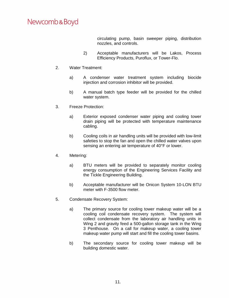
11.
circulating pump, basin sweeper piping, distribution nozzles, and controls.
2) Acceptable manufacturers will be Lakos, Process Efficiency Products, Puroflux, or Tower-Flo.
2. Water Treatment:
a) A condenser water treatment system including biocide
injection and corrosion inhibitor will be provided.
b) A manual batch type feeder will be provided for the chilled water system.
3. Freeze Protection:
a) Exterior exposed condenser water piping and cooling tower
drain piping will be protected with temperature maintenance cabling.
b) Cooling coils in air handling units will be provided with low-limit safeties to stop the fan and open the chilled water valves upon sensing an entering air temperature of 40°F or lower.
4. Metering:
a) BTU meters will be provided to separately monitor cooling
energy consumption of the Engineering Services Facility and the Tickle Engineering Building.
b) Acceptable manufacturer will be Onicon System 10-LON BTU meter with F-3500 flow meter.
5. Condensate Recovery System: a) The primary source for cooling tower makeup water will be a
cooling coil condensate recovery system. The system will collect condensate from the laboratory air handling units in Wing 2 and gravity feed a 500-gallon storage tank in the Wing 3 Penthouse. On a call for makeup water, a cooling tower makeup water pump will start and fill the cooling tower basins.
b) The secondary source for cooling tower makeup will be
building domestic water.

12.
6. Temporary Cooling for Tickle Engineering Building:
a) During construction of the Engineering Services Building, the two existing air-cooled chillers serving the Tickle Engineering Building will be temporarily relocated along the north wall of the building. Each of the two chillers will be reconnected to the building chilled water system using 4” schedule 40 steel piping with groove fittings on temporary supports along the north sidewalk.
b) Temporary chilled water piping will be insulated with cellular glass pipe insulation with vapor retarder. Insulation will be finished in aluminum jacket.
F. Process Chilled Water System:
1. Process chilled water will be provided by the process chilled water
system. Process chilled water will be distributed to Nuclear Engineering laboratories, flexible laboratories, and student design areas to provide cooling water for various uses. The process chilled water system will consist of heat exchangers, process chilled water pumps, and piping.
2. Heat Exchangers:
a) Heat exchangers plate and frame type with free-standing,
unitized frame and multiple stainless-steel plates. Two units will be provided – each sized for 100% of the peak building load with design entering water temperature of 60°F and design leaving water temperature of 50°F. One heat exchanger will be connected to chilled water for warm weather use and the other heat exchanger will be connected to condenser water for wintry weather use.
b) Acceptable manufacturers will be Armstrong, Bell & Gossett, or Taco.
3. Process Chilled Water Pumps:
a) The heating water pumps will be base-mounted, end-suction
type with premium efficiency motors sized to prevent overloading at any point along the pump curve. The pumps will have variable frequency drives to modulate flow to maintain a constant system differential pressure. Three pumps will be provided with each pump sized for 50% of the peak building load.
b) Acceptable manufacturers will be Bell & Gossett or Taco.

13.
4. Piping:
a) Process chilled water piping 2.5" and larger will be ERW
schedule 40 black steel and 2" and smaller will be type L hard drawn copper. Piping will be insulated with preformed fiberglass pipe insulation with white all service jacket with self-sealing lap.
b) ¾” valved stubouts will be provided in Nuclear Engineering laboratories, flexible laboratories, and student design areas. See architectural drawings for valved stubout locations.
5. Chemical Treatment:
a) A manual batch type feeder will be provided.
G. Air Conditioning Systems:
1. Air Handling Units for Offices, Classrooms and Other Non-Laboratory Areas:
a) Air handling units will be draw-through, factory-fabricated,
medium pressure recirculating type consisting of air blenders, filters, cooling coils, preheat coils, premium efficiency motors, variable frequency drives, supply fans, solid 2” double-wall casings, and spring vibration isolation. Air handling units will be located in the Penthouse.
b) Air blenders: counter rotation design for mixing of outside air and return air streams.
c) Preheat coils: heating water type with inline circulating pump
for freeze protection.
d) Cooling coils: coils will be selected for air velocities not more than 450 fpm and for a 16°F chilled water temperature differential.
e) Humidification: None required.
f) Filtration: MERV 14 cartridge filters with MERV 8 pleated
prefilters.
g) Supply fans: a total of 6 or more fans with N+1 redundancy will be provided in a fan array arrangement such that the unit can operate at full capacity if any one fan has failed. Fans will be controlled by two variable frequency drives.

14.
h) Relief fans: each air handling unit will be provided with a relief
air fan located in the Penthouse. Relief air fans will be centrifugal-inline mixed flow fans.
i) Units will be zoned and sized as follows:
1) AHU-P1-1 Wing 1 Levels 1-5 22,000 CFM 2) AHU-P1-2 Wing 1 Levels 1-5 22,000 CFM 3) AHU-P2-3 Atrium/Public Areas 18,500 CFM 4) AHU-P3-1 Wing 3 27,000 CFM 5) AHU-P4-1 Wings 4 & 1 Ground Level 23,000 CFM 6) AHU-P4-2 Wing 4 Levels 1-3 30,000 CFM
j) Acceptable manufacturers will be Carrier, JCI, or Trane.
2. Air Handling Units for Laboratories:
a) Air handling units will be 100% outside air, custom-manufactured type consisting of filters, cooling coils, preheat coils, energy recovery coils, humidifiers, high premium-efficiency motors, supply fans, solid 2" double-wall casings, and spring vibration isolation. Air handling units will be located in the Penthouse.
b) Preheat coils: heating water type with inline circulating pump for freeze protection.
c) Cooling coils: coils will be selected for air velocities not more
than 450 fpm, and for a 16ºF chilled water temperature differential.
d) Humidification: steam manifold humidifiers within the unit will
be provided.
e) Energy recovery coils: high-efficiency runaround loop coil with 30% glycol/water mixture to recover energy from the laboratory exhaust. Coils will be furnished by the manufacturer of the Integrated, high-efficiency, runaround-type energy recovery system.
f) Filtration: MERV 14 cartridge filters with MERV 8 pleated prefilters.
g) Supply fans: a total of 6 or more fans with N+1 redundancy
will be provided in a fan array arrangement such that the unit can operate at full capacity if any one fan has failed. Fans will be controlled by two variable frequency drives.

15.
h) Units will be zoned and sized as follows:
1) AHU-P2-1 Wing 2 45,000 CFM 2) AHU-P2-2 Wing 2 45,000 CFM
i) Acceptable manufacturers will be Carrier, JCI, or Trane.
3. Nuclear Engineering Computer Server Laboratory:
a) The Computer Server Laboratory will be served by computer room air conditioning units. Units will be glycol-cooled, floor-mounted units with ducted top discharge. Remote dry cooler with unit-mounted pump package will be located on the roof.
b) Two nominal 5-ton units will be provided.
c) Acceptable manufacturers will be Airflow, Liebert, or Stulz.
4. Communication and Audio-Visual Rooms:
a) The communication rooms throughout the building will be served by ductless split systems. Units will be provided with wall-mounted indoor units and outdoor units located on the roof.
b) Nominal 1-ton units will be provided for each room.
c) Acceptable manufacturers will be Daikin, Carrier, or LG.
5. Elevator Machine Rooms:
a) Elevator machine rooms will be served by independent ductless split systems as required by the International Building Code – 2012. Units will be provided with wall-mounted indoor units and outdoor units located on the roof.
b) Nominal 1-ton units will be provided for each room.
c) Acceptable manufacturers will be Daikin, Carrier, or LG.
6. Mechanical Rooms:
a) Mechanical rooms will be ventilated with exhaust fans and heated with unit heaters.

16.
b) Ventilation fan for the Ground Level Main Mechanical Room will also serve as emergency exhaust in the event of a refrigerant leak from the centrifugal chillers.
7. Ductwork:
a) Ductwork will conform to SMACNA recommendations and will
have the following static pressure classifications:
1) From laboratory air handling unit supply fans to supply air valves: 6” wg.
2) From other air handling units to supply terminal units: 4” wg.
3) From terminal units and supply air valves to grilles, registers and diffusers: 2” wg.
4) From laboratory exhaust fans to general exhaust, fume hood exhaust, and snorkel exhaust air valves: -4” wg.
5) From general exhaust air valves to grilles and registers: -2” wg.
6) From fume hood exhaust air valves to fume hoods: -2” wg.
7) Snorkel exhaust ductwork (student design): -3” wg.
8) Return air and toilet exhaust ductwork: -2” wg.
9) Stairwell pressurization ductwork: 4” wg.
10) Atrium smoke removal exhaust ductwork: -2” wg.
11) Other ductwork: 2” wg.
12) Plenums and casings on the suction side of air handling units: -4” wg.
b) Medium-pressure supply ductwork (4” and 6” wg) in
mechanical rooms and concealed locations will be factory-fabricated, single-wall, round or flat oval ductwork.
c) Medium-pressure supply ductwork (4” and 6” wg) and low-pressure ductwork (2” wg) exposed in student design and laboratory spaces will be factory-fabricated, double-wall, round or flat oval ductwork with 2” thick fiberglass insulation and a

17.
perforated sheet metal liner. See architectural drawings for locations where ceilings are open.
d) Ductwork will be galvanized steel, except as follows:
1) Laboratory exhaust ductwork: type 304 stainless steel with welded longitudinal seams.
a) Exception: Ductwork from ceiling registers to
general exhaust air valves will be galvanized steel.
e) Longitudinal seams and transverse joints in non-welded
ductwork will be sealed.
f) Ductwork will be insulated for energy conservation and to prevent condensation as follows:
1) Exposed supply air, outside air, and mixed air ductwork
will be insulated with 2" rigid fiberglass board insulation finished with 8 oz. canvas set in white lagging adhesive.
2) Concealed supply air ductwork will be insulated with 2" flexible fiberglass insulation.
3) Exterior exhaust ductwork will be insulated with 2" mineral wool board insulation finished with 0.020" thick aluminum lagging.
4) Duct lining will not be used.
8. Smoke and Fire Dampers:
a) Combination fire/smoke dampers will be provided in smoke barriers and where horizontal supply, return and exhaust mains exit vertical shafts.
b) Fire dampers will be provided in fire-rated construction.
9. Terminal Units:
a) Variable-volume reheat terminal units will provide heating/cooling supply air to offices, classrooms, and other non-laboratory areas. Heat will be provided by heating water coils.

18.
b) Constant-volume exhaust terminal units will provide control of snorkel exhaust in student design areas.
c) Acceptable manufacturers will be Enviro-Tec, JCI, or Titus.
10. Air Valves:
a) A mixture of constant-volume and variable-volume supply air
valves will provide heating/cooling for laboratory zones. Where reheat is required, duct-mounted heating water coils will be provided downstream of supply air valves.
b) A mixture of constant-volume and variable-volume general
exhaust air valves will provide space pressurization in laboratory zones.
c) Variable-volume exhaust air valves will provide control of
airflow at fume hoods.
d) Constant-volume exhaust air valves will provide control of snorkel exhaust in laboratory areas.
e) Acceptable manufacturers will be Phoenix Controls or Price.
11. Return Air:
a) Return air from offices, classrooms and other non-laboratory
areas will be hard-ducted from ceiling-mounted grilles back to air handling units.
b) No return air will be allowed from laboratories.
12. Air Distribution Devices:
a) Plaque face diffusers will be used in offices, classrooms and other non-laboratory areas with lay-in ceilings.
b) Laminar flow diffusers will be used in laboratories and laboratory support rooms.
c) Linear diffusers will be used in the atrium, elevator lobbies, and other public spaces.
d) Double-deflection sidewall supply registers/grilles will be used
in exposed double-wall duct locations, electrical rooms, and other rooms without ceilings.

19.
e) Egg crate ceiling grilles will be used in offices, classrooms and other non-laboratory areas (12” x 24” and 24” x 24” only).
f) Egg crate ceiling registers will be used in laboratories, laboratory support rooms, break rooms, copy rooms and toilets (12” x 24” and 24” x 24” only).
g) Single-deflection sidewall return/exhaust registers/grilles will
be used in rooms without ceilings.
h) Acceptable manufacturers will be Nailor, E.H. Price, or Titus.
H. Exhaust Systems
1. Laboratory Exhaust:
a) A combined laboratory general exhaust, fume hood exhaust, and snorkel exhaust system will serve the laboratory spaces.
b) The exhaust system will be served by 3 exhaust fans, 2 running and 1 on standby. These fans will be variable-volume type and will discharge through high velocity vertical discharge nozzles. The high velocity will maximize dispersion of effluents and minimize contamination of nearby intake sources. The exhaust flow into the system from the building will vary as building exhaust changes in response to laboratory fume hood sash positions and space general exhaust airflow.
1) The maximum operating capacity of the system will be
95,000 CFM.
c) Exhaust systems will be designed for 100 fpm face velocity at each fume hood. A laboratory airflow controls system will vary the amount of air exhausted as a function of sash position to keep a constant face velocity. The supply air valve, a 2-way heating water control valve on the supply terminal reheat coil, and a general room exhaust valve will modulate as required to maintain room temperature and a minimum room air change rate of 6 per hour. When the room is unoccupied, the minimum air change rate will be reduced to 4 per hour. Supply and exhaust air valves will be controlled to maintain a fixed offset between supply and exhaust in each laboratory.
d) The exhaust system will include energy recovery coils and MERV 8 pleated filters located in the exhaust stream. Coils will be furnished by the manufacturer of the Integrated, high-efficiency, runaround-type energy recovery system.
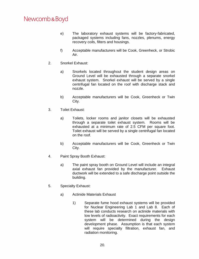
20.
e) The laboratory exhaust systems will be factory-fabricated, packaged systems including fans, nozzles, plenums, energy recovery coils, filters and housings.
f) Acceptable manufacturers will be Cook, Greenheck, or Strobic
Air.
2. Snorkel Exhaust:
a) Snorkels located throughout the student design areas on Ground Level will be exhausted through a separate snorkel exhaust system. Snorkel exhaust will be served by a single centrifugal fan located on the roof with discharge stack and nozzle.
b) Acceptable manufacturers will be Cook, Greenheck or Twin City.
3. Toilet Exhaust:
a) Toilets, locker rooms and janitor closets will be exhausted
through a separate toilet exhaust system. Rooms will be exhausted at a minimum rate of 2.5 CFM per square foot. Toilet exhaust will be served by a single centrifugal fan located on the roof.
b) Acceptable manufacturers will be Cook, Greenheck or Twin City.
4. Paint Spray Booth Exhaust:
a) The paint spray booth on Ground Level will include an integral
axial exhaust fan provided by the manufacturer. Exhaust ductwork will be extended to a safe discharge point outside the building.
5. Specialty Exhaust:
a) Actinide Materials Exhaust
1) Separate fume hood exhaust systems will be provided
for Nuclear Engineering Lab 1 and Lab 8. Each of these lab conducts research on actinide materials with low levels of radioactivity. Exact requirements for each system will be determined during the design development phase. Assumption is that each system will require specialty filtration, exhaust fan, and radiation monitoring.

21.
b) Additional specialty exhaust systems may include laminar flow
hood exhaust, radioisotope fume hood exhaust, or other specialty systems. Requirements for these systems will be determined during the design development phase.
6. Dust Collection Systems:
a) Dust collection systems will be specified by the Architect.
b) HVAC systems serving areas with dust collection will be
designed with controls as necessary to balance room airflow with dust collections systems on and off.
I. Energy Recovery Systems
1. Base Equipment: Standard Runaround-Type Energy Recovery
System
a) System equipment will include energy recovery coils, pumps, air control accessories, and controls.
b) Coils will be selected for 25% glycol-water mixture and sized to fit into their respective air handling units and high-induction exhaust fan system casings.
c) Pumps will be base-mounted, end-suction type with premium
efficiency motors sized to prevent overloading at any point along the pump curve. The pumps will have variable frequency drives to modulate flow to maintain a desired coil leaving air temperature. Two pumps will be provided with each pump sized for 100% of the peak load. 1) Acceptable manufacturers will be Bell & Gossett or
Taco.
d) Control and monitoring points will be provided by the building control system manufacturer.
2. Alternate Equipment: Integrated, High-Efficiency, Runaround-Type
Energy Recovery System:
a) System will be complete with energy recovery coils, hydronic module, and system controller designed to provide high-efficiency.
b) Coils will be designed to optimize performance. Coils will be selected for 25% glycol-water mixture and sized to fit into their

22.
respective air handling units and high-induction exhaust fan system casings.
c) Hydronic module will include redundant high-pressure
centrifugal pumps, variable frequency drives, expansion tank, air separator, control valves, isolation valves, interconnecting piping, and control cabinet mounted on a common structural steel skid.
d) System controller will provide demand-dependent regulation of
the entire energy recovery system, including controller hardware, software, and display unit for energy efficiency, temperatures, and volumetric flows. All remote inputs to the system controller will be provided by the building control system.
e) Manufacturer will provide written energy performance
guarantee, start-up services, optimization services, and three years of remote monitoring.
f) Acceptable manufacturer will be Konvekta-USA.
3. Piping:
a) Energy recovery water piping 2.5" and larger will be ERW
schedule 40 black steel and 2" and smaller will be type L hard drawn copper. Piping will be insulated with preformed fiberglass pipe insulation with white all service jacket with self-sealing lap.
J. Smoke Control Systems
1. Stairwell Pressurization:
a) Stairwell pressurization systems will be provided to control
smoke as required by Section 909.20.5 of the International Building Code – 2012. Stairwells will be pressurized with outside air to maintain 0.10" wg minimum differential pressure and 0.35” wg maximum differential pressure with all stairway doors closed. Fans will be direct-drive centrifugal type with variable frequency drives and located within the rated stairwell or on the roof. The systems will include multiple ducted discharge points in each stairwell.
b) Acceptable manufacturers will be Cook, Greenheck or Twin City.
2. Elevator Hoistway Pressurization:

23.
a) Elevator hoistway pressurization systems will be provided to
control smoke as required by Section 909.21 of the International Building Code – 2012. Hoistways will be pressurized with outside air to maintain 0.10" wg minimum differential pressure and 0.25” wg maximum differential pressure with all hoistway doors on the floor of recall open and all other hoistway doors closed. Fans will be direct-drive centrifugal type with variable frequency drives and located on the roof. The systems will include a single ducted discharge point at the top of each hoistway.
b) Acceptable manufacturers will be Cook, Greenheck or Twin City.
3. Atrium Smoke Removal:
a) Smoke removal and make-up air systems will be provided to
control smoke in the atrium as required by Section 909 of the International Building Code – 2012. Fans will be direct-drive centrifugal type with variable frequency drives.
b) Acceptable manufacturers will be Cook, Greenheck or Twin City.
K. Automatic Temperature Control Systems
1. An open-protocol, building control system (BCS), including a PC-
based operator system, will be provided to control the chiller plant, heating water systems, air handling units, exhaust systems, energy recovery systems, and terminal units. Acceptable manufacturers will be JCI or Schneider Electric.
a) Flood Detection: The BCS will include water sensors for the
shielded Ground Level Nuclear Engineering Labs enclosed by Column Lines L-R-2.1-2.2.
2. Variable-volume laboratory pressurization controls will be provided in
laboratory spaces. Controls will be fast-acting type to maintain CFM offsets in each space. Laboratory pressurization controls will monitor lighting systems to determine occupancy and setback the minimum ventilation rate during unoccupied periods. Pressurization controls will provide full interface with the BCS. Acceptable manufacturers will be Phoenix Controls or Price.

24.
L. HVAC Testing, Adjusting, and Balancing:
1. Systems will be tested, adjusted, and balanced to achieve proper` operation, design flow, temperature and pressure differentials, and pressure drop through piping, ductwork, equipment, and components.

25.
III. PLUMBING SYSTEMS
A. General:
1. Codes and Standards:
a) International Plumbing Code – 2012
2. Assumptions: a) The users of the building will not require natural gas as an
available utility. This was confirmed in the Consultants Coordination Meeting held on October 4, 2017.
b) Reclaimed rainwater will not be reused for flushing of urinals
and water closets as stated in the Program Verification Document dated May 15, 2017. This was confirmed in the Consultants Coordination Meeting held on October 4, 2017.
B. Plumbing Fixtures:
1. Water Closets:
a) Water closets will be elongated vitreous china, wall-hung,
sensor-activated, flush valve type, 1.28 gallons per flush with white open front seats (Zurn Z5615.381.01.91.00).
2. Lavatories:
a) Lavatories will be vitreous china, under-mount type, with
sensor-activated centerset faucet, 0.5 gpm flow control, and grid strainer (Zurn Z5220.975.1.07.B8.0).
3. Urinals:
a) Urinals will be vitreous china, wall-hung, sensor-activated,
flush valve type, 0.125 gallons per flush (Zurn Z5755.352.00).
4. Water Fountains:
a) Water fountains will be electric, modular type with in-wall
chiller, extended round receptors, and bottle filler option (Elkay LZWS-LRPBM28K-CLYQ).
5. Sinks:
a) Service sinks will be terrazzo, floor type with grid strainer, rim
guard and faucet with hose thread outlet, vacuum breaker and

26.
wall brace (Stern Williams HL-1800-T35-T40 and Zurn Z843M1-XL).
b) Break room sinks will be stainless steel, self-rimming type, with swing spout faucet, and 1.5 gpm flow control (Symmons S-23).
c) Laboratory sinks and faucets will be specified by the Architect
and provided by the casework manufacturer.
6. Showers:
a) Handicapped showers will be composed of pressure balanced valves set to prevent full hot, with metal lever handles, adjustable slide bars, and maximum 2.0 gpm handheld showers with braided hoses (Symmons 1-117-FS-X-L/HD with Oxygenics Elite SkinCare 700-XLF20).
7. Emergency Fixtures:
a) Emergency showers and eyewashes will be specified by the
Architect and provided by the casework manufacturer. Each emergency shower will be provided with a thermostatic type tempering valve to provide tepid water (between 60°F and 100°F) at point of use.
C. Drainage Systems
1. Sanitary Drainage System:
a) Sanitary drain, waste, and vent systems will extend from 5'
outside the building to all fixtures and equipment requiring service. Drainage and vent stacks will extend vertically through the roof. The system will be provided with traps, vents, and cleanouts as required by code. Trap primers will be provided for drains susceptible to loss of water seal by evaporation.
b) The elevator pit will be provided with a sump pump with
the discharge piped to sanitary system.
2. Rainwater Drainage System:
a) Rainwater primary and secondary drainage systems will extend from the roof drains to 5' outside the building. Cleanouts will be provided as required by code. Drain bodies and horizontal rainwater piping above grade will be insulated to prevent condensation. Rainwater

27.
secondary drainage piping will be routed independent of other drainage systems and discharge above grade at an observable location.
b) Architect will utilize scuppers in lieu of secondary rainwater drainage piping wherever possible.
3. Piping: a) Sanitary and rainwater drainage and vent piping above
grade will be hubless cast iron pipe and fittings with heavy-duty compression type couplings. Drainage and vent piping below grade will be service weight cast iron pipe and fittings with elastomeric compression joints.
D. Domestic Water Systems
1. Water Supply:
a) The water supply will be provided from municipal source
with service separate from fire suppression service.
2. Water Service:
a) The water service will be extended from 5' outside the building to the Ground Leve l Main Mechan ica l Room. The water service will be provided with dual R P Z backflow prevention devices (Wilkins 375AST-FSC-AG) in accordance with local code.
3. Water Distribution:
a) A central water pressure booster system will be provided to
serve the building. The system will be located in the Ground Level Main Mechanical Room and will be triplex type with vertical multi-stage pumps and VFD controllers.
b) Water serving the building will be split into two systems: domestic supply and laboratory supply. The laboratory supply system will be separated from the domestic water system by RPZ backflow preventers.
c) After passing through the building's main backflow preventers and a water pressure booster system, the domestic cold water supply will be piped to a dedicated water heater that will generate the domestic hot water supply. The domestic cold water and hot water will be distributed to toilet rooms, break

28.
rooms, and other areas where water may be required for human consumption.
d) Domestic cold water will feed one set of parallel backflow preventers (Wilkins 375AST-FSC-AG); downstream of these backflow preventers, the water will be designated as the laboratory cold water supply. Laboratory cold water will be piped to dedicated water heaters that will generate the laboratory hot water supply. Laboratory cold and hot water will be piped to laboratory fixtures and equipment (glassware washers, sterilizers, etc.).
e) Isolation valves will be provided at the building water
entrance, at the base or top of each vertical riser, at each branch to commons areas serving 2 or more fixtures, and at each wall hydrant or equipment connection. Water hammer arresters will be provided for shock suppression.
f) Water connections for mechanical system make-up will be
isolated from the domestic water system by RPZ backflow preventers (Wilkins 975XL2TCUSAG).
4. Hot Water:
a) Hot water service will be extended from water heaters to the
plumbing fixtures. Water heaters will be located in the Ground Level Main Mechanical Room. Separate water heaters will be provided for the domestic and laboratory systems. Two equally sized water heaters piped in parallel will be provided for each system. Water hammer arresters will be provided as required for shock suppression.
b) Water heaters will be the instantaneous, packaged coil steam-to-water heat exchanger type (PVI CSX). Heater systems will include the necessary steam control valves and traps, expansion tank, pumps, and thermostatic mixing valves. The fuel source will be steam provided from the campus distribution system.
c) Hot water circulating pumps will be provided to limit temperature loss throughout each system to 10°F maximum. Alternatively, self-regulating temperature maintenance cable may be used to reduce or eliminate the need for separate hot water circulating systems.
d) Hot water for each system will be heated to 140°F.

29.
e) Master thermostatic mixing valves will be installed near the water heater to reduce the hot water temperature to most fixtures and equipment in the building to 120ºF.
5. Piping:
a) Domestic water piping within the building will be type L hard copper with wrought copper sweat type fittings and joints using lead-free solder or press joint type fittings. Water piping below slabs on grade will be type K soft copper with no joints below slab.
b) Domestic hot and cold water piping will be insulated with fiberglass pipe insulation. Fittings will be insulated with preformed fiberglass fittings finished with glass fabric and vapor barrier mastic.
E. Laboratory Systems:
1. Laboratory g as systems will consist of laboratory compressed air,
laboratory vacuum, and piping.
a) Laboratory Compressed Air Systems:
1) Compressors will be oil-free scroll-type compressors with desiccant a ir dryers to a minimum of -4°F dew point. Compressed air systems will include compressed air receivers, air-cooled after-coolers, and pre- and post-filters to provide clean air.
2) Compressed air for general laboratory use will be
distributed at 50 psig. High-pressure compressed air will be provided for specific equipment as required.
3) Compressed air system will be interconnected with 2”
underground copper piping to nearby compressed air loop serving buildings on the Hill.
b) Laboratory Vacuum System:
1) A dry claw type laboratory vacuum system will be designed for 15" hg at casework outlets. A liquids-solids interceptor will be provided at the inlet to the system.

30.
c) Piping:
1) Piping for laboratory gas systems will be type L hard copper tubing, pre-cleaned for oxygen service with wrought copper fittings. Joints will be brazed with silver brazing alloy and continuously purged with nitrogen during brazing operations.
d) Specialty Gas Systems:
1) All specialty gases are to be provided by users using
local cylinder tanks.
2. Pure Water Systems:
a) Pure water system will extend from water treatment equipment to laboratory sinks and equipment throughout Wing 2 of the building. Pure water generation equipment will be Owner-furnished, Owner-installed.
b) Pure water piping distribution system will include vertical circulating loop with 3” risers between floors and a 1” horizontal circulating loop on each floor.
c) Pure water piping will be polypropylene pipe with butt or
socket fusion joints. Valves will be provided as necessary for isolation of piping branches.
3. Laboratory Drainage Systems:
a) A central neutralization/dilution system will be provided for acid
control of laboratory wastes prior to connection to the sanitary sewer. The system will be designed for vault/pit installation. The system will consist of a single tank and a separate sampling basin. Neutralizing system tanks will be high-density polyethylene or polypropylene with inlets, outlets, vents and access manway openings. A pH monitoring system and sampling basin will monitor effluent pH and will record outputs.
b) Chemical waste and vent piping below slab on grade will be non-fire-retardant polypropylene with electric coil socket thermal fusion joints. Chemical waste and vent piping above grade will be fire-retardant polypropylene with electric coil socket thermal fusion joints, except joints at waste arms and p-traps for laboratory sinks will be allowed to be mechanical.

31.
F. Student Design Area Systems
1. Shop Compressed Air:
a) Compressors will be reciprocating-type compressors with refrigerated air dryers to a minimum of 35°F dew point. Compressed air systems will include compressed air receivers, air-cooled after-coolers, and pre- and post-filters to provide clean air.
b) Compressed air for general shop use will be distributed at
120 psig.
c) Shop compressed air piping within the building will be type L hard copper with wrought copper sweat type fittings and joints using lead-free solder or press joint type fittings.
2. Shop Vacuum:
a) Outlets will be connected to the laboratory vacuum system
described above.
3. Central Vacuum:
a) Central vacuum system will be specified by the Architect.

32.
IV. ELECTRICAL SYSTEMS
A. General
1. Codes and Standards:
a) NFPA 70 – 2011, National Electrical Code
b) NFPA 110 – 2013, Emergency and Standby Power Systems
c) NFPA 780 – 2017, Installation of Lightning Protection Systems
2. Assumptions:
a) Nuclear Engineering SCIF Rooms:
1) Research Labs 5 and 13 will be designed as Sensitive Compartmented Information Facilities (SCIF). Assumption is that rooms will be modular pre-manufactured units complete with electrical devices, wiring, and raceways.
B. Demolition at Mechanical Room of Tickle Engineering Building:
1. The existing installation will remain as is except as otherwise indicated herein. New work will be connected to the existing work and the existing work adapted to the changes in the building and systems.
2. Equipment, apparatus, and exposed wiring and raceways rendered useless due to changes will be removed.
3. Material and equipment which has been removed will not be used in
the new work, except as indicated herein.
4. Where existing mechanical equipment is removed, electric wiring, raceways, switches and starters associated with the equipment will be removed.
5. Where existing mechanical equipment is modified or relocated, the electrical connections to the equipment will be modified to adapt them to their new function or location.
C. Primary Distribution System - Campus:
1. Type of System:
a) The campus primary electrical system is a 13, 200 V
underground primary distribution system.

33.
b) The primary feeders will originate from an existing manhole
along Lower Drive to the northwest of the building.
2. Duct Bank:
a) Underground concrete-encased duct bank will be used for primary feeder installation.
3. Medium Voltage Cables:
a) Cables will be single conductor, insulated, thermoplastic
jacketed and rated for 15000 V, 133% insulation level. Conductors will be copper with ethylene propylene rubber insulation.
4. Pad-Mount Transformers:
a) Pad-mount transformers will be 3-phase, oil-immersed, self-
cooled, 60 Hz, 65ºC rise, with primary voltage of 13200/7621 V delta-wye connected. Pad-mount transformers will be located outside the building and furnished by the Contractor.
b) Two 2500 kVA pad-mount transformers will be provided for the Engineering Services Building and one 3000 kVA pad-mount transformer will be provided for the Tickle Engineering Building.
c) Acceptable manufacturers will be Cooper Power Systems
General Electric Company, Siemens, or Square D Company.
5. Medium Voltage Switchgear:
a) Pad-mounted style, SF6 insulated medium voltage switchgear will be provided. Switch will be 6-way switch with six vacuum fault interrupter ways.
b) Switchgear will have remote supervisory controls and have capability to transmit to campus SCADA system.
c) Basis of design manufacturer will be S&C Vista.
d) Switchgear will be located on grade to the west of the Tickle
Bridge

34.
D. Interior Electrical Distribution System:
1. Electrical Service:
a) Electrical service for the Engineering Services Building will originate from two 2500 kVA pad-mount service transformers located on grade to the west of the Tickle Bridge. The contractor will furnish and install the primary and secondary service conductors and service transformers. Service to the building will be 480/277 V, 3- phase, 4-wire, wye connected, grounded neutral.
b) A separate electrical service will be provided to the
Engineering Services Building Fire Pump Room from one of the pad-mount service transformers.
c) Electrical service for the Tickle Engineering Building will
originate from a 3000 kVA pad-mount service transformer located on grade to the west of the Tickle Bridge. The contractor will furnish and install the primary and secondary service conductors and service transformer. Service to the building will be 480/277 V, 3- phase, 4-wire, wye connected, grounded neutral.
d) In general, loads will be served as follows:
Load Service LED lighting 277V
Motors 0.5 hp and larger 480 V, 3-phase
Receptacles and motors 120 V, single-phase 0.33 hp and smaller through the use of step-down transformers
2. Service Equipment:
a) Service equipment will consist of a double-ended 4000A
switchgear. The service switchgear will be arranged in a main-tie-main configuration with key interlocked main and tie breakers. The service switchgear will be front and rear accessible, with individually mounted main and feeder devices. Switchgear bussing will be copper and will be braced for the available fault current. Main and tie devices will be insulated case, draw-out type circuit breakers. Feeder devices will be the same as main devices.
b) Service switchgear will be arc flash resistant type.

35.
c) Service switchgear will be provided with surge protective
devices as described herein.
d) Acceptable manufacturers will be Cutler-Hammer, General Electric Company, Siemens, or Square D Company.
3. Ground Fault Protection:
a) Ground fault protection will be provided for 480 V services and
feeders 1000 A and larger.
b) Main and feeder devices in the service switchgear will be provided with ground fault protection.
4. Duct Bank:
a) Underground concrete-encased duct bank will be used for secondary feeder installation.
5. Meters:
a) The service switchgear will be provided with an electronic
power monitor. The monitor will be a microprocessor-based device with capability for future connection to a remote host computer. Metered values (true RMS) will include multiphase amperes and volts, watts, VARS, volt-amps, watt-hours and VAR-hours, amperes and watts demand, frequency, power factor, and harmonic distortion.
6. Panelboards:
a) Branch circuit panelboards will be provided on each floor to
serve the lighting and receptacles.
b) Protective devices in panelboards will be bolt-on type circuit breakers. Buswork will be copper. Lighting and receptacle panelboards will have a minimum 15% spare circuit breakers plus 10% spaces for future circuit breakers. From each flush mounted panelboard, a minimum of six spare empty conduits will be provided.
c) Panelboards will be equipped with surge protective devices as
described herein.
d) Each Student Design Area will be provided with a combination of 480V and 208V panelboards for flexibility.

36.
7. Uninterruptible Power Supplies:
a) The Nuclear Engineering Computer Server Laboratory will be provided with two uninterruptible power supplies. The UPS will be continuous duty, on-line, solid state type consisting of inverter, rectifier/battery charger, static bypass transfer switch, internal maintenance bypass switch, synchronizing circuitry, external battery, protective devices and accessories. The UPS will automatically maintain continuity of electric power without interruption, upon failure or deterioration of the input AC power source. The battery protection time for the UPS will be 10 minutes.
b) Acceptable manufacturers will be Cyberex, EPE Technologies, Liebert, or Mitsubishi.
8. Wiring:
a) Wiring will be insulated conductors installed in raceways.
Conductors will be copper with type THWN/THHN or XHHW insulation. Conductors for power wiring will be a minimum of #12 AWG and a maximum of 500 kcmil.
9. Raceways:
a) Minimum raceway size will be 0.75" for power.
b) Raceways will not be allowed to be embedded in floor slabs
unless serving individual floor boxes.
c) Electrical Metallic Tubing:
1) In concrete and masonry construction above grade, in hollow spaces in columns and walls, and above suspended ceilings.
2) Exposed raceways in unfinished areas.
d) Rigid Metal Conduit:
1) For exposed raceways serving fire pumps, jockey
pumps, fire pump control equipment, and other applications not otherwise specified herein.
e) Flexible Metal Conduit:
1) Connections to recessed luminaires, maximum 72”
lengths.

37.
2) Connections to motors, engine-generator sets, and dry-
type transformers.
3) Connections to electrical equipment subject to movement or vibration.
f) Liquid tight Flexible Metal Conduit:
1) Connections to equipment exposed to rain or spray.
2) Connections to electrical equipment subject to
movement or vibration where exposed to rain, spray, or a corrosive atmosphere
3) Connections to equipment subject to oil or grease,
including drips or spills.
4) Connections to fire pumps and auxiliary equipment.
g) Conduit Fittings and Bodies (for Metallic Conduit):
1) Conduit and cable fittings will be galvanized steel.
2) Conduit bodies will be cast steel or aluminum.
h) Surface Metal Raceways:
1) Aluminum surface metal raceways will be used for power and communication devices in laboratories. Surface metal raceways will be installed on the wall above benches.
10. Wiring Devices:
a) Wall switches and duplex receptacles will be specification
grade. Device faceplates will be type 302 stainless steel. Faceplates serving emergency power receptacles will be engraved to indicate panel and circuit number. Faceplates serving normal power receptacles will be labeled to indicate panel and circuit number.
b) Receptacles will be installed a maximum of 50’ on center in corridors. Duplex receptacles will be provided on each wall for offices. Each workstation will be provided two duplex receptacles.

38.
11. Grounding:
a) The electrical systems, circuits, and equipment will be grounded and bonded. The maximum resistance of electrical systems to ground will be 3 ohms.
b) A ground riser system consisting of #4/0 copper ground risers and copper ground busses will be provided. Ground busses will be located in each electrical room and communications room.
12. Equipment Grounds:
a) A green identified grounding conductor will be installed in raceways with the phase conductors.
E. Lighting:
1. Generally, interior lighting will be LED type.
2. Luminaires:
a) Enclosed offices: suspended, low-profile indirect/direct LED
luminaires with dimmer controls for daylight harvesting and individual control.
b) Open offices: suspended, low-profile indirect/direct LED
luminaires with dimmer controls for daylight harvesting and individual control.
c) Atrium, lobbies and corridors: recessed LED downlights.
d) Conference rooms: recessed indirect/direct LED luminaires
with dimmer controls.
e) Classrooms: recessed indirect/direct LED luminaires with dimmer controls.
f) Laboratories: suspended, low-profile indirect/direct LED
luminaires.
g) Mechanical and electrical rooms: industrial type LED luminaires.
h) Means of egress: in accordance with NFPA 101-2012.

39.
3. Illumination Levels:
a) Illumination levels, 30" above the finished floor, for work surfaces will be based on IESNA lighting standards as scheduled below:
Area Maintained Average Illumination Level in Foot-candles (with indirect lighting)
Office Space: Workstation space 30 Conference rooms (adjustable) 30 Corridors 10-20 Laboratories 50-100 Classrooms 30 Public Areas: Entrance lobbies 10-30 Corridors 10-20 Elevator lobbies 10-20 Support Spaces: Toilets 20 Storage and janitor's closets 20 Electrical Rooms 30 Mechanical Rooms 30 Communications Rooms 50 Specialty Areas: As required
4. Building Lighting Controls:
a) Automatic control devices will be provided to shut off building
lighting in all spaces. Automatic control devices will be occupancy sensor type.
b) Daylight harvesting controls will be provided for building perimeter spaces to dim electric lighting systems in response to available natural day lighting. Control systems will consist of photo sensors, dimming drivers, and daylight controllers. This system will be fully commissioned.
c) Each space enclosed by ceiling-height partitions will be
provided with an occupancy sensor to independently control the general lighting within the space.
d) Exterior lighting will be controlled by a combination of a photo
sensor and time switch.

40.
5. Architectural Dimming Control Systems:
a) Architectural dimming control systems will be provided for the
following individual spaces:
1) Conference rooms.
2) Classrooms.
b) Architectural dimming control systems will consist of the following basic components:
1) Master preset control stations for manual light level
setting of each control zone and for preset scene selection.
2) Dimming panels or dimming modules for dimming of light sources.
c) Acceptable manufacturer will be Lutron.
F. Emergency Power Supply System:
1. The emergency power supply system will include a 1500 kW
enginegenerator set with control panel, automatic transfer switch systems, remote annunciator panel, and accessories to automatically supply power during a utility power failure. The system will assume the emergency power load within 10 seconds, the legally required loads between 10 and 30 seconds, and the optional stand-by loads between 30 and 60 seconds after a utility power loss. 25% additional spare capacity will be provided for research.
a) Engine-Generator Sets:
1) Diesel engines: engines will be water-cooled, inline or
vee compression type designed to operate on No. 2 fuel oil. Radiators will be unit mounted.
2) Generators: generators will be 480/277 V, 3-phase, 4-
wire, single-bearing, synchronous type, wet-wound, tropicalized with Class H insulation with permanent magnet pilot exciter.
3) Power rating: engine-generator sets will have standby
rating. Rating will be based on operation at rated rpm when equipped with operating accessories, including air cleaners, lubricating oil pump, fuel transfer pump,

41.
fuel injection pumps, jacket water pump, governor, alternating current generator, radiator fan, and exciter regulator.
4) Fuel tank: sub-base fuel tank with fuel capacity for 48
hours runtime at 100% rated kW capacity. Tank will be double-wall with rupture alarm and will incorporate a locking exterior fill, vent, supply/return, and level gauge. Tank and accessories will comply with UL 142-2006 and meet state and local code requirements.
5) Load bank: load bank will be of the same size as the
generator radiator core and will be cooled by utilizing the air outflow of the engine radiator. Load bank will be sized at 50% of generator capacity.
6) Enclosure: enclosure will be factory-assembled,
factory-wired, walk-in, weatherproof type.
7) Silencers: critical grade, cylindrical style.
8) Circuit breakers: unit-mounted circuit breakers will be provided to feed automatic transfer switches and the fire pump.
9) Acceptable manufacturers will be Caterpillar,
Cummins, or Kohler.
b) Automatic Transfer Switches:
1) Automatic transfer switches will include a switched neutral and pretransfer signal load control.
2) Acceptable manufacturers will be ASCO or Russelectric.
2. Emergency Power Supply System Loads:
a) Egress lighting and exit lights.
b) Fire detection and alarm systems.
c) Engine-generator set auxiliaries.
d) Elevators (arranged for simultaneous operation of one per
group on emergency)
e) Smoke control systems.

42.
f) Lighting and receptacles in main and emergency electrical
rooms.
g) Public safety communication systems.
h) Sump pumps.
i) Laboratory exhaust systems.
j) Laboratory air handling units.
k) Air conditioning systems for elevator machine rooms, communications rooms, and computer server rooms.
l) Building control systems.
m) Lighting and receptacles in communications and electrical rooms.
n) Airflow monitor/audible-visual alarms for fume hoods.
o) Environmental rooms, laboratory freezers, and refrigerators.
p) Select receptacles in laboratory modules.
q) Specific laboratory equipment requiring emergency power.
3. Temporary Emergency Power for Tickle Engineering Building:
a) During construction of the Engineering Services Building, the
existing engine-generator set serving the Tickle Engineering Building will be temporarily relocated adjacent to the storage building with rooftop patio on east side of the Tickle Bridge. A new underground ductbank will be installed from the temporary engine-generator set location to the Tickle Engineering Building emergency distribution system. A portion of this ductbank will be combined with the emergency ductbank that serves the Engineering Services Facility.
G. Fire Pumps: 1. Fire pumps will be supplied from the following sources:
a) Service connection dedicated to the fire pumps.
b) The emergency power supply system.

43.
2. Supply conductors will connect to a listed fire pump transfer switch.
H. Surge Protective Devices:
1. Surge protective devices (SPDs) will be installed at the main switchgear, distribution panelboards, telephone service entrance, fire alarm control panel, and other selected equipment. In addition, other underground cabling entering the building will be provided with SPDs.
2. Devices will be internally mounted and provided with coordinated
overcurrent protection in switchboards and panel boards.
I. Lightning Protection System:
1. A lightning protection system will be provided, and will be the concealed type installed in compliance with UL requirements.
J. Short-Circuit and Coordination Study:
1. A complete short-circuit and coordination study incorporating equipment furnished will be provided by the Contractor to confirm the interrupting and withstand capacities of the final equipment selection and to determine the final settings of adjustable overcurrent protection devices.
2. An arc-fault study will be provided to identify potential fault energy
levels at each switchboard and panelboard. From that study, labels on equipment will be provided describing the hazard level and required personnel protective equipment when working within the equipment.

44.
V. FIRE ALARM SYSTEMS
A. General
1. Codes and Standards
a) NFPA 70-2011, National Electrical Code
b) NFPA 72-2010, National Fire Alarm Code
2. Quality Assurance:
a) Fire alarm equipment will be the product of SimplexGrinnell or Edwards. Work to be performed will include expansion and modification of the existing SimplexGrinnell 4190 or Edwards EST3 color graphics system at the campus central electrical shop.
B. Design Criteria:
1. The fire alarm system will be a supervised, local protective signaling
system employing multiplex communication and individually addressable initiating devices.
2. The fireman's telephone system will be a 2-way system employing telephone jacks and portable handsets. The fireman's telephone system may be combined with the fire alarm system. Fireman's telephone system will include telephone jacks and speakers in the elevator cabs.
3. Preaction sprinkler control panels, smoke detectors, heat detectors, and connections to preaction valves will be provided.
4. Wiring will be installing in metallic raceways.
C. Control Equipment:
1. Fire alarm equipment requiring user interface will be located in the
Ground Level Fire Command Center.
2. Control equipment will be modular in construction, UL listed, and housed in a recessed steel cabinet. Operating voltage will be 24 V DC. Standby power will be furnished by a 24-hour self-contained emergency battery power supply.
3. The main fire alarm control panel will include solid-state construction,
plug-in modules and dead' front construction. Signaling line circuits and initiating device circuits will be arranged so that the number of

45.
connected devices does not exceed 75% of circuit capacity. The fire alarm annunciator will be an LCD display with minimum 80-character capacity. The control panel will include a voice record and playback unit.
4. Speaker circuits will be selectable for 1-way transmission of voice
instructions. The circuit selector panel will be mounted adjacent to or integral with the CPU and will include individual zone selector switches, an all-call switch, and a microphone with press-to-call button and coil cord.
5. The power supplies and amplifiers will be distributed throughout the
building.
6. A firefighter’s smoke control panel with graphic will be provided. D. Alarm Initiating Devices:
1. Alarm initiating devices will include addressable manual pull stations,
monitor modules, duct detectors, heat detectors, and smoke detectors. Addressable monitor modules will be provided for nonaddressable devices including sprinkler water flow switches, sprinkler pressure switches, valve tamper switches, and fire pump status.
E. Notification Devices:
1. Alarm signaling devices will consist of speakers and strobe lights.
2. Auxiliary functions will be performed by control modules located
within 36" of the controls for the equipment to be operated. F. Fireman's Telephones and Jacks:
1. Jacks will be flush-mounted stainless-steel type.
2. 5 portable handsets with plugs and coil cords will be provided in a
cabinet adjacent to the fire alarm panel.
3. Telephone jacks in elevator lobbies will be incorporated in elevator call buttons and coordinated with the elevator equipment.

46.
VI. FIRE SUPPRESSION SYSTEMS
A. General:
1. Codes and Standards:
a) NFPA 13-2010, Installation of Sprinkler Systems
b) NFPA 14-2010, Installation of Standpipe and Hose Systems
c) NFPA 20-2010, Installation of Centrifugal Fire Pumps
2. Design Criteria:
a) The building will be protected throughout by a combined system of Class I wet standpipes and automatic sprinklers.
b) Areas subject to freezing, including loading docks, will be protected by a dry pipe sprinkler system.
c) The shielded Ground Level Nuclear Engineering Labs
enclosed by Column Lines L-R-2.1-2.2 will be protected by a double interlock preaction sprinkler system.
3. Assumptions:
a) An on-site secondary fire water supply tank will not be
provided as required by Section 903.3.5.2 of the International Building Code–2012. Instead, the Architect and Code Consultant will develop a Request for Equivalency like the one used for the Strong Hall and Mossman projects.
B. Sprinkler System:
1. Piping will be sized by hydraulic calculations. Laboratories,
mechanical rooms, electrical rooms, and storage areas will be classified Ordinary Hazard Group 1. Ground Level Wings 1 & 4 (including wood shop, metal shop, and other student design areas) will be classified Ordinary Hazard Group 2. Other areas will be classified Light Hazard. Hydraulic design criteria will be in accordance with NFPA 13-2010 as follows:
a) Light hazard areas will be designed to provide a minimum
density of 0.10 gpm/ft2. Maximum area per sprinkler will be 225 ft2.

47.
b) Ordinary Hazard Group 1 areas will be designed to provide a minimum density of 0.15 gpm/ft2. Maximum area per sprinkler will be 130 ft2.
c) Ordinary Hazard Group 2 areas will be designed to provide a
minimum density of 0.20 gpm/ft2. Maximum area per sprinkler will be 130 ft2.
d) Minimum design area will be the most hydraulically demanding
1500 ft² for wet systems and 2000 ft² for dry systems.
e) A simultaneous inside hose demand of 100 gpm will be included for light hazard areas and 250 gpm for ordinary hazard areas.
f) Sprinkler connections on each floor will include a monitored
control valve, a flow switch, and a test/drain connection. A drain riser with discharge at the building exterior will also be provided to serve each sprinkler system.
C. Standpipe System:
1. Wet standpipes will be located within heated stairwells. Additional
standpipes, if required, will be provided so that all portions of all floors are within reach of a 200' hose. Hose thread pattern will match the local fire department pattern.
D. Sprinkler Heads:
1. Sprinklers will be commercial, quick response, UL listed type.
2. Sprinklers in areas having lay-in ceilings will be semi-recessed
pendent type with a white finish and white ceiling cup. Sprinklers in grid ceilings will be aligned and located in the center of tiles.
3. Sprinklers in the atrium, lobbies, and other areas with sheetrock ceilings will be concealed type with custom color cover plates. Colors will be selected by the Architect.
E. Piping:
1. Aboveground piping will be black steel with threaded, grooved, or
welded fittings. Piping 2" and smaller will be schedule 40 and pipe 2.5" and larger will be schedule 10. No plain-end fittings, strap-on branch outlets, or couplings employing set screws will be used. Pump suction piping and piping subject to alternate wetting and drying will be galvanized. Underground piping will be cement-lined

48.
ductile iron with mechanical joints. Underground piping will be anchored with concrete thrust blocks and tie rods.
F. Water Supply:
1. Water supply will be fed from two separate 8” connections to the city
mains. A UL-listed, ASSE-approved reduced pressure detector backflow preventer will be installed on each fire water service to isolate the fire suppression systems from the potable water.
G. Fire Pump:
1. One electric motor-driven, horizontal split case fire pump will be
located in the Ground Level Fire Pump Room. The pump will be rated at 1000 gpm.
2. Two fire department Siamese connections and one fire pump test header will be provided. These devices will be wall-mounted or freestanding.
3. Fire pump controllers will be UL listed for use with electric motor-driven fire pumps and will include the motor starter, power transfer switch, and solid-state reduced-voltage starting.
H. Monitoring:
1. The fire suppression system will be monitored by the building fire
alarm system. Monitor points will include trouble and alarm conditions for water flow switches, valve tamper switches, and fire pump status.

49.
VII. LIFE CYCLE COST ANALYSIS
A. Introduction:
1. This narrative contains background information and alternative descriptions of Life Cycle Cost Analyses for the Engineering Services Facility on the University of Tennessee Knoxville campus. These Life Cycle Cost Analyses are required by the Tennessee High Performance Building Requirements Manual - 2015.
2. For each analysis, the first costs, maintenance costs, energy consumption, and utility costs were calculated and compared to determine the life cycle costs for each option.
3. The utility costs of electricity and campus steam for buildings at the
University of Tennessee Knoxville campus were utilized in the analyses as indicated in Appendix A.
B. Methodology:
1. The software utilized to perform the energy analysis was an MS Excel
spreadsheet incorporating a modified bin data method calculation. The bin data from the appropriate climate, as published by Air Force Weather Service, was applied to calculate the design cooling and heating loads.
C. Description of Options:
1. Option 1: Provide standard runaround-type energy recovery system
to recovery heat between laboratory exhaust and outside air streams. Energy recovery coils provided by AHU manufacturer. Pumps provided by Armstrong, Bell & Gossett or Taco. Controls provided building control system manufacturer.
a) The winter design effectiveness of this option is 25%.
2. Option 2: Provide integrated, high-efficiency runaround-type energy recovery system to recovery heat between laboratory exhaust and outside air streams. Energy recovery coils provided by Konvekta. Pumps and controls combined on a hydronic module package and provided by Konvekta.
a) The winter design effectiveness of this option is 65%.
b) The first cost for this option includes a 100 ton reduction in the
chiller plant size from 1900 total tons to 1800 total tons.

50.
D. Results:
1. Option 1 – Standard Runaround-Type Energy Recovery System:
a) Initial Net Cost = $298,232
b) First Year Energy Cost = $453,159
c) 20-Year Life Cycle Cost = $13,005,173
2. Option 2 – Integrated, High-Efficiency Runaround-Type Energy Recovery System
a) Initial Net Cost = $662,075
b) First Year Energy Cost = $407,369
c) Simple Payback = 7.9 years
d) Life Cycle Cost = $12,142,979

51.
APPENDIX A
LIFE CYCLE COST ANALYSIS
ADDITIONAL INFORMATION

20 Study Period (Years)
3.0% Utility Inflation Rate
3.0% Annual O&M Inflation Rate
2.75% Discount Rate
298,232$ Initial Net Cost
453,159$ First Year Energy Costs
5,965$ Annual O&M Cost
13,005,173$ Life Cycle Cost
Annual Cash Flow Annual Cash Flow
Year Costs
Operating
Costs
Cost
Adjustments:
Maint. Contract,
etc. Life Cycle Cost
Net Present
Value of Total
Costs
0 298,232$ 298,232$ 298,232$
1 466,754$ 6,144$ 472,898$ 460,241$
2 480,757$ 6,328$ 487,085$ 461,361$
3 495,180$ 6,518$ 501,697$ 462,484$
4 510,035$ 6,713$ 516,748$ 463,609$
5 525,336$ 6,915$ 532,251$ 464,737$
6 541,096$ 7,122$ 548,218$ 465,868$
7 557,329$ 7,336$ 564,665$ 467,001$
8 574,049$ 7,556$ 581,605$ 468,137$
9 591,270$ 7,782$ 599,053$ 469,276$
10 609,008$ 8,016$ 617,024$ 470,418$
11 627,279$ 8,256$ 635,535$ 471,563$
12 646,097$ 8,504$ 654,601$ 472,710$
13 665,480$ 8,759$ 674,239$ 473,860$
14 685,444$ 9,022$ 694,466$ 475,013$
15 706,008$ 9,293$ 715,300$ 476,169$
16 727,188$ 9,571$ 736,759$ 477,327$
17 749,004$ 9,859$ 758,862$ 478,489$
18 771,474$ 10,154$ 781,628$ 479,653$
19 794,618$ 10,459$ 805,077$ 480,820$
20 818,456$ 10,773$ 829,229$ 481,990$
21 N/A N/A N/A N/A
22 N/A N/A N/A N/A
23 N/A N/A N/A N/A
24 N/A N/A N/A N/A
25 N/A N/A N/A N/A
Totals 298,232$ 12,541,861$ 165,080$ 13,005,173$ 9,718,957$
Standard Runaround Energy Recovery System
UTK ESF
Life Cycle Cost Analysis 12/14/2017

20 Study Period (Years)
3.0% Utility Inflation Rate
3.0% Annual O&M Inflation Rate
2.75% Discount Rate
662,075$ Initial Net Cost
407,369$ First Year Energy Costs
7,456$ Annual O&M Cost
12,142,979$ Life Cycle Cost
Annual Cash Flow
Year Costs
Operating
Costs
Cost
Adjustments:
Maint. Contract,
etc. Life Cycle Cost
Net Present
Value of Total
Costs
0 662,075$ 662,075$ 662,075$
1 419,591$ 7,679$ 427,270$ 415,835$
2 432,178$ 7,910$ 440,088$ 416,846$
3 445,144$ 8,147$ 453,291$ 417,861$
4 458,498$ 8,392$ 466,889$ 418,877$
5 472,253$ 8,643$ 480,896$ 419,896$
6 486,420$ 8,903$ 495,323$ 420,918$
7 501,013$ 9,170$ 510,183$ 421,942$
8 516,043$ 9,445$ 525,488$ 422,969$
9 531,525$ 9,728$ 541,253$ 423,998$
10 547,470$ 10,020$ 557,490$ 425,030$
11 563,895$ 10,321$ 574,215$ 426,064$
12 580,811$ 10,630$ 591,442$ 427,100$
13 598,236$ 10,949$ 609,185$ 428,139$
14 616,183$ 11,278$ 627,460$ 429,181$
15 634,668$ 11,616$ 646,284$ 430,225$
16 653,708$ 11,964$ 665,673$ 431,272$
17 673,320$ 12,323$ 685,643$ 432,322$
18 693,519$ 12,693$ 706,212$ 433,373$
19 714,325$ 13,074$ 727,399$ 434,428$
20 735,755$ 13,466$ 749,220$ 435,485$
21 N/A N/A N/A N/A
22 N/A N/A N/A N/A
23 N/A N/A N/A N/A
24 N/A N/A N/A N/A
25 N/A N/A N/A N/A
Totals 662,075$ 11,274,554$ 206,350$ 12,142,979$ 9,173,836$
Integrated, High Efficiency Runaround Energy Recovery System
UTK ESF
Life Cycle Cost Analysis 12/14/2017

Un
ive
rsit
y o
f T
en
ne
ss
ee
at
Kn
ox
vil
le
En
gin
eeri
ng
Se
rvic
es F
acil
ity
AN
NU
AL
EN
ER
GY
CO
NS
UM
PT
ION
- S
TA
ND
AR
D R
UN
AR
OU
ND
EN
ER
GY
RE
CO
VE
RY
SY
ST
EM
12/1
4/2
01
7
17N
070
Air C
hara
cte
ristic
s:
Div
ers
ities:
Su
pp
ly A
ir C
FM
=9
50
00
Effectiv
en
ess =
25
01
-08
Div
ers
ity =
10
0
09
-16
Div
ers
ity =
10
0
%
Ou
tsid
e A
ir =
10
0U
tilit
y C
osts
:1
7-2
4 D
ivers
ity =
10
0
Ele
ctr
icity
($
/ (
kW
- H
)) =
0.0
80
Tem
pera
ture
of A
ir E
xitin
g C
oil
=5
1F
an
Co
st:
Ste
am
($
/ m
mb
tu)
=9
.33
Sta
tic P
ressu
re =
11
En
thalp
y o
f A
ir E
xitin
g C
oo
ling
Co
il =
20
.8S
tatic
Effic
ien
cy
=0
.65
Ch
iller
Pla
nt E
ffic
ien
cy
(kW
/ T
on
) =
0.7
3M
axi
mu
m F
an
HP
=2
52
.9
Ro
om
Dry
Bu
lb =
75
(No
te: In
clu
de to
tal s
tatic
pre
ssu
re fo
r su
pp
ly a
nd
retu
rn)
To
tal B
uild
ing
Are
a (
Sq
Ft)
=4
0,0
00
En
thalp
y o
f R
etu
rn / E
xhau
st A
ir =
28
.2
Min
imu
m O
uts
ide A
ir D
esig
n T
em
pera
ture
=1
9.9
Alti
tud
e (
FT
) =
50
0
Maxi
mu
m W
inte
r D
elta
-T =
5
Coolin
g C
alc
ula
tions:
Ou
tsid
e A
irH
ours
Air L
eavin
g E
nerg
y R
eco
ve
ryM
ixe
d A
irC
oolin
g L
oad
Exte
nde
d C
lgE
xte
nde
d F
an H
PT
ime
MC
DB
En
thalp
y0
1-0
80
9-1
61
7-2
4E
nth
alp
yD
ry B
ulb
En
thalp
yD
ry B
ulb
To
ns
To
n -
Ho
urs
HP
- H
/ Y
ear
Pe
rce
nta
ge
deg
rees F
btu
/lb
dry
air
btu
/lb
dry
air
deg
rees F
btu
/lb
dry
air
deg
rees F
57.1
12
0.5
93
109
83
20.5
57.1
20.5
57.1
-11
-304
672088
3.1
8%
57.6
32
1.5
52
85
74
21.5
57.6
21.5
57.6
25
5262
53371
2.3
5%
59.4
22
2.5
66
64
75
22.5
59.4
22.5
59.4
61
12415
51853
2.2
9%
60.8
02
3.5
69
51
73
23.5
60.8
23.5
60.8
96
18564
48818
2.1
5%
62.0
42
4.5
77
62
63
24.5
62.0
24.5
62.0
132
26626
51094
2.2
5%
64.0
32
5.5
98
73
93
25.5
64.0
25.5
64.0
167
44204
66776
2.9
4%
65.9
02
6.5
90
78
76
26.5
65.9
26.5
65.9
203
49547
61718
2.7
2%
66.8
72
7.5
103
98
98
27.5
66.9
27.5
66.9
239
71368
75629
3.3
3%
68.5
72
8.5
117
103
86
28.5
68.6
28.5
68.6
274
83940
77400
3.4
1%
70.1
32
9.5
126
87
120
29.5
70.1
29.5
70.1
310
103209
84229
3.7
1%
71.3
73
0.5
135
76
103
30.5
71.4
30.5
71.4
346
108507
79423
3.5
0%
74.1
53
1.5
90
127
87
31.5
74.2
31.5
74.2
381
115881
76894
3.3
9%
75.7
03
2.5
76
107
101
32.5
75.7
32.5
75.7
417
118375
71835
3.1
7%
76.1
53
3.5
106
110
100
33.5
76.2
33.5
76.2
452
142970
79929
3.5
2%
77.6
13
4.5
105
122
103
33.6
74.1
33.6
74.1
458
151010
83470
3.6
8%
77.7
23
5.5
117
112
121
35.1
76.0
35.1
76.0
508
177905
88529
3.9
0%
80.0
33
6.5
51
84
124
35.7
76.7
35.7
76.7
530
137271
65512
2.8
9%
82.4
93
7.5
25
73
80
37.0
80.6
37.0
78.5
578
102962
45023
1.9
8%
84.4
53
8.5
9107
54
37.9
82.1
37.9
79.5
610
103657
43000
1.9
0%
85.1
53
9.5
488
28
38.9
82.6
38.9
80.5
644
77255
30353
1.3
4%
86.0
44
0.5
043
13
39.8
83.3
39.8
82.0
677
37936
14165
0.6
2%
86.1
94
1.5
131
54
0.8
83.4
40.8
81.0
713
26369
9359
0.4
1%
86.8
94
2.5
09
04
1.8
83.9
41.8
83.9
747
6721
2276
0.1
0%
88.6
74
3.5
03
04
2.6
85.2
42.6
80.5
778
2335
759
0.0
3%
-4
4.5
00
0-
-#
VA
LU
E!
#V
AL
UE
!0
00
0.0
0%
-4
5.5
00
0-
-#
VA
LU
E!
#V
AL
UE
!0
00
0.0
0%
-4
6.5
00
0-
-#
VA
LU
E!
#V
AL
UE
!0
00
0.0
0%
-4
7.5
00
0-
-#
VA
LU
E!
#V
AL
UE
!0
00
0.0
0%
-4
8.5
00
0-
-#
VA
LU
E!
#V
AL
UE
!0
00
0.0
0%
-4
9.5
00
0-
-#
VA
LU
E!
#V
AL
UE
!0
00
0.0
0%
-5
0.5
00
0-
-#
VA
LU
E!
#V
AL
UE
!0
00
0.0
0%
-5
1.5
00
0-
-#
VA
LU
E!
#V
AL
UE
!0
00
0.0
0%
-5
2.5
00
0-
-#
VA
LU
E!
#V
AL
UE
!0
00
0.0
0%
-5
3.5
00
0-
-#
VA
LU
E!
#V
AL
UE
!0
00
0.0
0%
-5
4.5
00
0-
-#
VA
LU
E!
#V
AL
UE
!0
00
0.0
0%
Re
-He
atin
g H
ours
:1155
1458
1299
Co
olin
g T
ota
ls:
1,7
21
,243
1,3
33
,504
58.7
8%
Heat
Reco
very
Unit

Un
ive
rsit
y o
f T
en
ne
ss
ee
at
Kn
ox
vil
le
En
gin
eeri
ng
Se
rvic
es F
acil
ity
AN
NU
AL
EN
ER
GY
CO
NS
UM
PT
ION
- S
TA
ND
AR
D R
UN
AR
OU
ND
EN
ER
GY
RE
CO
VE
RY
SY
ST
EM
12/1
4/2
01
7
17N
070
Heating C
alc
ula
tions:
Ou
tsid
e A
irH
ours
Air L
vg
. E
n. R
ec.
Mix
ed A
irH
eatin
g L
oad
Exte
nde
d H
tgE
xte
nde
d F
an H
PT
ime
Dry
Bu
lb0
1-0
80
9-1
61
7-2
4D
ry B
ulb
Dry
Bu
lbB
TU
/HkB
TU
/ Y
ear
HP
- H
/ Y
ear
Pe
rce
nta
ge
deg
rees F
deg
rees F
deg
rees F
-17.5
00
0-
N/A
00
00
.00%
-12.5
00
0-
N/A
00
00
.00%
-7.5
00
0-
N/A
00
00
.00%
Bu
ildin
g T
ota
ls:
-2.5
00
0-
N/A
00
00
.00%
2.5
00
0-
N/A
00
00
.00%
7.5
40
02
4.4
N/A
5759969
23040
1012
0.0
4%
12.5
14
25
28.1
N/A
5371656
112805
5312
0.2
3%
17.5
24
98
31.9
N/A
4983344
204317
10371
0.4
6%
He
atin
g C
ost
($ / Y
ear)
:$
21
7,0
07.6
8
22.5
92
15
23
35.6
N/A
4595031
597354
32882
1.4
5%
27.5
124
50
74
39.4
N/A
4206719
1043266
62729
2.7
7%
Co
olin
g C
ost
($ / Y
ear)
:$
10
0,5
20.6
2
32.5
198
107
141
43.1
N/A
3818406
1703009
112812
4.9
7%
37.5
288
193
190
46.9
N/A
3430094
2301593
169723
7.4
8%
Fa
n O
pera
tio
n C
ost
($ / Y
ear)
:$
13
0,8
10.3
7
42.5
235
140
219
50.6
N/A
3041781
1806818
150247
6.6
2%
ER
P O
pera
tio
n C
ost
($ / Y
ear)
:$
3,9
18.8
0
47.5
196
122
211
54.4
N/A
2653469
1403685
133806
5.9
0%
To
tal C
ost
($ / (
Sq
Ft
- Y
ear)
):$
11
.31
52.5
238
217
258
58.1
N/A
2265156
1615056
180347
7.9
5%
57.5
196
220
241
61.9
N/A
1876844
1233086
-7
.33%
To
tal C
ost
($ / (
CF
M -
Ye
ar)
):$
4.7
2
62.5
396
320
287
65.6
N/A
1488531
1492997
-1
1.1
8%
Re
-He
at
1155
1458
1299
--
2485200
9722102
-4
3.6
2%
To
tal E
ne
rgy
Co
st/
ye
ar
$45
3,1
59.4
6
He
atin
g T
ota
ls:
23,2
59,1
29
859
,240
100
.00%

Un
ive
rsit
y o
f T
en
ne
ss
ee
at
Kn
ox
vil
le
En
gin
eeri
ng
Se
rvic
es F
acil
ity
AN
NU
AL
EN
ER
GY
CO
NS
UM
PT
ION
- IN
TE
GR
AT
ED
, H
IGH
EF
FIC
IEN
CY
EN
ER
GY
RE
CO
VE
RY
SY
ST
EM
12/1
4/2
01
7
17N
070
Air C
hara
cte
ristic
s:
Div
ers
ities:
Su
pp
ly A
ir C
FM
=9
50
00
Effectiv
en
ess =
65
01
-08
Div
ers
ity =
10
0
09
-16
Div
ers
ity =
10
0
%
Ou
tsid
e A
ir =
10
0U
tilit
y C
osts
:1
7-2
4 D
ivers
ity =
10
0
Ele
ctr
icity
($
/ (
kW
- H
)) =
0.0
80
Tem
pera
ture
of A
ir E
xitin
g C
oil
=5
1F
an
Co
st:
Ste
am
($
/ m
mb
tu)
=9
.33
Sta
tic P
ressu
re =
11
En
thalp
y o
f A
ir E
xitin
g C
oo
ling
Co
il =
20
.8S
tatic
Effic
ien
cy
=0
.65
Ch
iller
Pla
nt E
ffic
ien
cy
(kW
/ T
on
) =
0.7
3M
axi
mu
m F
an
HP
=2
52
.9
Ro
om
Dry
Bu
lb =
75
(No
te: In
clu
de to
tal s
tatic
pre
ssu
re fo
r su
pp
ly a
nd
retu
rn)
To
tal B
uild
ing
Are
a (
Sq
Ft)
=4
0,0
00
En
thalp
y o
f R
etu
rn / E
xhau
st A
ir =
28
.2
Min
imu
m O
uts
ide A
ir D
esig
n T
em
pera
ture
=1
9.9
Alti
tud
e (
FT
) =
50
0
Maxi
mu
m W
inte
r D
elta
-T =
5
Coolin
g C
alc
ula
tions:
Ou
tsid
e A
irH
ours
Air L
eavin
g E
nerg
y R
eco
ve
ryM
ixe
d A
irC
oolin
g L
oad
Exte
nde
d C
lgE
xte
nde
d F
an H
PT
ime
MC
DB
En
thalp
y0
1-0
80
9-1
61
7-2
4E
nth
alp
yD
ry B
ulb
En
thalp
yD
ry B
ulb
To
ns
To
n -
Ho
urs
HP
- H
/ Y
ear
Pe
rce
nta
ge
deg
rees F
btu
/lb
dry
air
btu
/lb
dry
air
deg
rees F
btu
/lb
dry
air
deg
rees F
57.1
12
0.5
93
109
83
20.5
57.1
20.5
57.1
-11
-304
672088
3.1
8%
57.6
32
1.5
52
85
74
21.5
57.6
21.5
57.6
25
5262
53371
2.3
5%
59.4
22
2.5
66
64
75
22.5
59.4
22.5
59.4
61
12415
51853
2.2
9%
60.8
02
3.5
69
51
73
23.5
60.8
23.5
60.8
96
18564
48818
2.1
5%
62.0
42
4.5
77
62
63
24.5
62.0
24.5
62.0
132
26626
51094
2.2
5%
64.0
32
5.5
98
73
93
25.5
64.0
25.5
64.0
167
44204
66776
2.9
4%
65.9
02
6.5
90
78
76
26.5
65.9
26.5
65.9
203
49547
61718
2.7
2%
66.8
72
7.5
103
98
98
27.5
66.9
27.5
66.9
239
71368
75629
3.3
3%
68.5
72
8.5
117
103
86
28.5
68.6
28.5
68.6
274
83940
77400
3.4
1%
70.1
32
9.5
126
87
120
29.5
70.1
29.5
70.1
310
103209
84229
3.7
1%
71.3
73
0.5
135
76
103
30.5
71.4
30.5
71.4
346
108507
79423
3.5
0%
74.1
53
1.5
90
127
87
31.5
74.2
31.5
74.2
381
115881
76894
3.3
9%
75.7
03
2.5
76
107
101
32.5
75.7
32.5
75.7
417
118375
71835
3.1
7%
76.1
53
3.5
106
110
100
33.5
76.2
33.5
76.2
452
142970
79929
3.5
2%
77.6
13
4.5
105
122
103
33.6
74.1
33.6
74.1
458
151010
83470
3.6
8%
77.7
23
5.5
117
112
121
35.1
76.0
35.1
76.0
508
177905
88529
3.9
0%
80.0
33
6.5
51
84
124
35.7
76.7
35.7
76.7
530
137271
65512
2.8
9%
82.4
93
7.5
25
73
80
36.3
77.6
36.3
78.5
552
98264
45023
1.9
8%
84.4
53
8.5
9107
54
37.0
78.3
37.0
79.5
576
97996
43000
1.9
0%
85.1
53
9.5
488
28
37.9
78.6
37.9
80.5
608
72956
30353
1.3
4%
86.0
44
0.5
043
13
38.7
78.9
38.7
82.0
638
35752
14165
0.6
2%
86.1
94
1.5
131
53
9.7
78.9
39.7
81.0
673
24904
9359
0.4
1%
86.8
94
2.5
09
04
0.6
79.2
40.6
79.2
705
6341
2276
0.1
0%
88.6
74
3.5
03
04
1.3
79.8
41.3
80.5
730
2190
759
0.0
3%
-4
4.5
00
0-
-#
VA
LU
E!
#V
AL
UE
!0
00
0.0
0%
-4
5.5
00
0-
-#
VA
LU
E!
#V
AL
UE
!0
00
0.0
0%
-4
6.5
00
0-
-#
VA
LU
E!
#V
AL
UE
!0
00
0.0
0%
-4
7.5
00
0-
-#
VA
LU
E!
#V
AL
UE
!0
00
0.0
0%
-4
8.5
00
0-
-#
VA
LU
E!
#V
AL
UE
!0
00
0.0
0%
-4
9.5
00
0-
-#
VA
LU
E!
#V
AL
UE
!0
00
0.0
0%
-5
0.5
00
0-
-#
VA
LU
E!
#V
AL
UE
!0
00
0.0
0%
-5
1.5
00
0-
-#
VA
LU
E!
#V
AL
UE
!0
00
0.0
0%
-5
2.5
00
0-
-#
VA
LU
E!
#V
AL
UE
!0
00
0.0
0%
-5
3.5
00
0-
-#
VA
LU
E!
#V
AL
UE
!0
00
0.0
0%
-5
4.5
00
0-
-#
VA
LU
E!
#V
AL
UE
!0
00
0.0
0%
Re
-He
atin
g H
ours
:1155
1458
1299
Co
olin
g T
ota
ls:
1,7
02
,410
1,3
33
,504
58.7
8%
Heat
Reco
very
Unit

Un
ive
rsit
y o
f T
en
ne
ss
ee
at
Kn
ox
vil
le
En
gin
eeri
ng
Se
rvic
es F
acil
ity
AN
NU
AL
EN
ER
GY
CO
NS
UM
PT
ION
- IN
TE
GR
AT
ED
, H
IGH
EF
FIC
IEN
CY
EN
ER
GY
RE
CO
VE
RY
SY
ST
EM
12/1
4/2
01
7
17N
070
Heating C
alc
ula
tions:
Ou
tsid
e A
irH
ours
Air L
vg
. E
n. R
ec.
Mix
ed A
irH
eatin
g L
oad
Exte
nde
d H
tgE
xte
nde
d F
an H
PT
ime
Dry
Bu
lb0
1-0
80
9-1
61
7-2
4D
ry B
ulb
Dry
Bu
lbB
TU
/HkB
TU
/ Y
ear
HP
- H
/ Y
ear
Pe
rce
nta
ge
deg
rees F
deg
rees F
deg
rees F
-17.5
00
0-
N/A
00
00
.00%
-12.5
00
0-
N/A
00
00
.00%
-7.5
00
0-
N/A
00
00
.00%
Bu
ildin
g T
ota
ls:
-2.5
00
0-
N/A
00
00
.00%
2.5
00
0-
N/A
00
00
.00%
7.5
40
05
1.4
N/A
2964119
11856
1012
0.0
4%
12.5
14
25
53.1
N/A
2782906
58441
5312
0.2
3%
17.5
24
98
54.9
N/A
2601694
106669
10371
0.4
6%
He
atin
g C
ost
($ / Y
ear)
:$
16
2,6
75.9
0
22.5
92
15
23
56.6
N/A
2420481
314663
32882
1.4
5%
27.5
124
50
74
58.4
N/A
2239269
555339
62729
2.7
7%
Co
olin
g C
ost
($ / Y
ear)
:$
99
,420
.76
32.5
198
107
141
60.1
N/A
2058056
917893
112812
4.9
7%
37.5
288
193
190
61.9
N/A
1876844
1259362
169723
7.4
8%
Fa
n O
pera
tio
n C
ost
($ / Y
ear)
:$
13
0,8
10.3
7
42.5
235
140
219
63.6
N/A
1695631
1007205
150247
6.6
2%
ER
P O
pera
tio
n C
ost
($ / Y
ear)
:$
11
,756
.41
47.5
196
122
211
65.4
N/A
1514419
801128
133806
5.9
0%
To
tal C
ost
($ / (
Sq
Ft
- Y
ear)
):$
10
.12
52.5
238
217
258
67.1
N/A
1333206
950576
180347
7.9
5%
57.5
196
220
241
68.9
N/A
1151994
756860
-7
.33%
To
tal C
ost
($ / (
CF
M -
Ye
ar)
):$
4.1
4
62.5
396
320
287
70.6
N/A
970781
973694
-1
1.1
8%
Re
-He
at
1155
1458
1299
--
2485200
9722102
-4
3.6
2%
To
tal E
ne
rgy
Co
st/
ye
ar
$40
7,3
69.4
3
He
atin
g T
ota
ls:
17,4
35,7
88
859
,240
100
.00%

University of Tennessee at Knoxville
Engineering Services Facility
17N070
14-Dec-17
Initial Net Cost (Does not including piping and insulation since identical for both options)
Standard Runaround Loop Heat Recovery
Cost per Total
Item Quantity Units Unit Cost
Standard System (2 Pumps, Coils, Controls) 1 EA $250,000.00 $250,000.00
Subtotal $250,000.00
19.29% Markups* $48,231.80
Total Cost $298,231.80
Integrated, High Efficiency Runaround Loop Heat Recovery
Cost per Total
Item Quantity Units Unit Cost
Integrated, High Efficiency System 1 EA $580,000.00 $580,000.00
Chiller Plant Capacity Reduction 100 Tons -$250.00 -$25,000.00
Subtotal $555,000.00
19.29% Markups* $107,074.60
Total Cost $662,074.60
* Markups include General Conditions, Bond, Fee, Contingencies and Escalation

Utility Costs
12/14/2017
Electric rates from July, 2017 Billing Average based on July 2017 usage
18th Street Substation (GSD)
Electrical energy (on peak) $0.09712 /KWh Avg cost/kwh = $0.08252 $24.18 /mmbtu
Electrical energy (off peak) (200) $0.07322 /KWh
Electrical energy (off peak) (200) $0.02770 /KWh
Electrical energy (off peak) (>400) $0.02551 /KWh
Electrical demand on peak $10.41 /KW
Electrical demand maximum $5.43 /KW on peak 2,277,736 kwh $221,214
off peak (200) 3,519,441 kwh $257,693
off peak (200) 3,519,441 kwh $97,489
off peak (>400) 3,053,531 kwh $77,896
on peak 21,569 kw $224,533
off peak 21,486 kw $117,120
$24,820 Fac rental, etc.
$1,020,764 total
Laurel Substation (GSC)
Electrical energy (on peak) $0.09695 /KWh Avg cost/kwh = $0.08016 $23.49 /mmbtu
Electrical energy (off peak) (200) $0.07305 /KWh
Electrical energy (off peak) (200) $0.02863 /KWh
Electrical energy (off peak) (>400) $0.02535 /KWh
Electrical demand on peak $10.41 /KW
Electrical demand maximum $5.56 /KW on peak 1,374,371 kwh $133,245
off peak (200) 2,168,105 kwh $158,380
off peak (200) 2,168,105 kwh $62,073
off peak (>400) 2,235,127 kwh $56,660
on peak 13,108 kw $136,454
off peak 12,995 kw $72,880
$17,220 Fac rental, etc.
$636,913 total
Combined both substations 20,315,857 kwh Average cost/kwh =$0.08160 $23.91 /mmbtu

Utility Costs
12/14/2017
Water $3.39 /100 CFT (FY 2017 average) $0.0045 /gallon
Sewer $7.12 /100 CFT (FY 2017 average) $0.0095 /gallon
$0.0141 /gallon
Water Sewer
Rates: 1-2 ccf $1.55 $0.85 /ccf
(per meter) 3-10 ccf $3.65 $11.10 /ccf
(KUB Schedule February, 2017) 11-100 ccf $4.50 $9.90 /ccf
101-400 ccf $3.25 $8.50 /ccf
401-5000 ccf $2.10 $6.90 /ccf
>5000 ccf $1.00 $4.30 /ccf
Gas - Steam Plant Interuptible (July, 2017)
Gas cost calculation Extended costs for gas
Projected approximate rates Transport $15,451 (0-30,000 therms)
$0.30863 Commodity cost $77,576 (30,000-200,000 therms)
$0.51503 $0.20640 /therm (0-30,000 therms) $113,439 (200,000-500,000 therms)
$0.45633 $0.14770 /therm (30,000-200,000 therms) $140,652 (>500,000 therms)
$0.37813 $0.06950 /therm (200,000-500,000 therms) $180 customer charge
$0.35163 $0.04300 /therm (>500,000 therms) $347,298 total
Average based on 900,000 Therms $3.86 /mmbtu
Gas - Firm (Based on JARTU) (7/17) $0.8937 /therm $8.94 /mmbtu
Steam $9.33 /KLb (2017) $9.33 /mmbtu
Coal $98.75 /ton (9/1/13 - 8/31/18) $3.80 /mmbtu
Fuel oil $1.7378 /gallon (7/18/17) $13.37 /mmbtu
130,000 BTU/Gal
Gasoline $1.6822 /gallon (7/18/17) $13.46 /mmbtu
125,000 BTU/Gal

WWR ENGINEERS, INC.
KNOXVILLE, TENNESSEE
UNIVERSITY OF TENNESSEE KNOXVILLE
ESF BUILDING
Thursday, December 14, 2017
NOTES: SD BUDGET ACCESS/IDS
ITEM QTY. PRICE MATERIAL LABOR PER QTY. LABOR HOURS RATE LABOR
LSP CABINET W/CONTROLLER, URI, ETC 14 $5,200.00 $72,800.00 8.00 14 112 $75.00 $8,400.00
REQUEST TO EXIT (REX) 97 $150.00 $14,550.00 1.00 97 97 $75.00 $7,275.00
I-CLASS READER/MAG-STRIPE 97 $320.00 3.00 97 291 $75.00 $21,825.00
LOCK CONNECTION $0.00 $0.00 3.00 134 402 $75.00 $30,150.00
3/4" conduit/wire (per ft.) ACCESS 25000 $4.66 $116,500.00 0.06 25000 1500 $65.00 $97,500.00
PROGRAMMING, STARTUP, TESTING 14 8.00 14 112 $75.00 $8,400.00
PER DOOR LICENSE * 134 $100.00 $13,400.00 0 $0.00
REMOTE ARMING TERMINAL (RAT) 12 $285.00 $3,420.00 1.00 12 12 $75.00 $900.00
RADIATION AREA IDS 1 $8,500.00 $8,500.00 1.00 1 1 $6,000.00
TOTAL MATERIAL COST $229,170.00
TOTAL LABOR COST $180,450.00
TOTAL $409,620.00
* INC. CLASSROOM &DPS ONLY DOORS

WWR ENGINEERS, INC.
KNOXVILLE, TENNESSEE
UNIVERSITY OF TENNESSEE KNOXVILLE
ESF BUILDING
Monday, December 14, 2017
NOTES: SD BUDGET - A/V
ITEM QTY. PRICE MATERIAL LABOR PER QTY. LABOR HOURS RATE LABOR
FLOOR BOXES (LOT) 1 $45,000.00 $45,000.00 1.00 1 1 $40,000.00
conduit/wire (per ft.) 6000 $7.18 $43,080.00 0.20 6000 1200 $65.00 $78,000.00
UT SUPPLIED EQUIPMENT (SEE BELOW) 1.00 $2,017,400.00 $2,017,400.00 0
TOTAL MATERIAL COST $2,105,480.00
TOTAL LABOR COST $118,000.00
TOTAL $2,223,480.00


WWR ENGINEERS, INC.
KNOXVILLE, TENNESSEE
UNIVERSITY OF TENNESSEE KNOXVILLE
ESF BUILDING
Monday, December 14, 2017
NOTES: SD - CLOCKS
ITEM QTY. PRICE MATERIAL LABOR PER QTY. LABOR HOURS RATE LABOR
12" SINGLE DIAL 60 $195.00 $11,700.00 2.00 0 $65.00 $0.00
12" DBL DIAL $420.00 $0.00 3.00 28 84 $65.00 $5,460.00
3/4" conduit/wire (PER CLOCK.) 1400 $3.70 $5,180.00 0.05 1400 70 $65.00 $4,550.00
PROGRAMMING, STARTUP, TESTING 1.00 28 28 $65.00 $1,820.00
TOTAL MATERIAL COST $16,880.00
TOTAL LABOR COST $11,830.00
TOTAL $28,710.00

WWR ENGINEERS, INC.
KNOXVILLE, TENNESSEE
UNIVERSITY OF TENNESSEE KNOXVILLE
ESF BUILDING
Thursday, December 14, 2017
NOTES: SD BUDGET - DATA/COMM
DATA CABLE AND ASSOCIATED HARDWARE.
ITEM QTY. PRICE MATERIAL LABOR PER QTY. LABOR HOURS RATE LABOR
18" CABLE TRAY 5000 $13.30 $66,500.00 0.20 5000 975 $70.00 $68,250.00
DATA OUTLET W/PIPE, WIRE, ETC. 1538 $190.00 $292,220.00 1.50 1538 2307 $70.00 $161,490.00
SINGLE MODE BACKBONE 4000 $1.75 $7,000.00 0.10 4000 400 $70.00 $28,000.00
200 PR COPPER SERVICE ENTRANCE 300 $8.00 $2,400.00 0.10 300 30 $70.00 $2,100.00
COMM RACK WITH PATCH PANELS 14 $2,600.00 $36,400.00 12.00 14 168 $70.00 $11,760.00
4x5" CONCRETE ENCASED DUCT BANK 150 $40.00 $6,000.00 2.00 150 300 $65.00 $19,500.00
FLOOR SLEEVES 50 $250.00 $12,500.00 1.25 50 63 $65.00 $4,062.50
TOTAL MATERIAL COST $423,020.00
TOTAL LABOR COST $295,162.50
TOTAL $718,182.50

WWR ENGINEERS, INC.
KNOXVILLE, TENNESSEE
UNIVERSITY OF TENNESSEE KNOXVILLE
ESF BUILDING
Monday, December 14, 2017
NOTES: SD BUDGET - CCTV
ITEM QTY. PRICE MATERIAL LABOR PER QTY. LABOR HOURS RATE LABOR
15 TB NVR W/LICENSE 2 $11,250.00 $22,500.00 5.00 3 15 $90.00 $1,350.00
FIXED CAMERA W/LICENSE 16 $1,150.00 $18,400.00 4.00 16 64 $90.00 $5,760.00
PTZ CAMERA W/LICENSE 2 $3,725.00 $7,450.00 1.00 2 2 $90.00 $180.00
3/4" conduit/wire (per ft.) ACTIVE (33) 4000 $4.05 $16,200.00 0.05 4000 200 $90.00 $18,000.00
3/4" conduit/wire (per ft.) FUTURE (33) 4000 $4.05 $16,200.00 0.05 4000 200 $90.00 $18,000.00
PROGRAMMING, STARTUP, TESTING 16 8.00 13 104 $90.00 $9,360.00
TOTAL MATERIAL COST $80,750.00
TOTAL LABOR COST $52,650.00
TOTAL $133,400.00

WWR ENGINEERS, INC.
KNOXVILLE, TENNESSEE
UNIVERSITY OF TENNESSEE KNOXVILLE
ESF BUILDING
Monday, December 14, 2017
NOTES: SD BUDGET - DIST. ANTENNA
ITEM QTY. PRICE MATERIAL LABOR PER QTY. LABOR HOURS RATE LABOR
800mhz SYSTEM (LOT) 1 $74,000.00 $74,000.00 1.00 1 1 $24,000.00 $24,000.00
RADIATION AREA 1 $54,000.00 $68,000.00 1.00 1 1 $20,000.00 $20,000.00
PROGRAMMING, STARTUP, TESTING 1 1.00 1 1 $12,000.00 $12,000.00
TOTAL MATERIAL COST $142,000.00
TOTAL LABOR COST $56,000.00
TOTAL $198,000.00
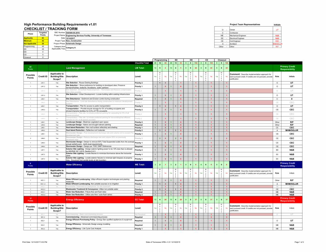
High Performance Building Requirements v1.01 Project Team Representatives Initials
CHECKLIST / TRACKING FORM O - Owner UT
SBC Number: 540/009-05-2016 C - Contractor
Project Name: Engineering Services Facility, University of Tennessee ME - Mechanical Engineer N&B
Applicable 83 Date: 12/14/2017 EE - Electrical Engineer N&B
Minimum 42 Project Type: New_Construction CE - Civil Engineer CEC
Not Applicable 20 Project Phase: Schematic Design A - Architect MHM/SGJJR
Programming 48 Other - Other R/F
SD 48
DD 0
CD 0
Closeout 0
Checklist Total 48 12 44 48 13 43 0 0 104 0 0 104 0 0 104
22
PointsLand Management LM Total: 13 5 4 13 4 5 0 0 22 0 0 22 0 0 22
Possible
PointsCredit ID
Applicable to
Building/Site
Scope?
Description Level: Yes
M
a
y
b
e
No Yes
M
a
y
b
e
No Yes
M
a
y
b
e
No Yes
M
a
y
b
e
No Yes
M
a
y
b
e
No
Comment: Describe implementation approach for
each pursued credit. If credits are not pursued, provide
justification.
Role Initials
1 LM1.1 Yes Site Selection - Reuse Existing Buildings Priority 2 1 0 1 1 1 1 O UT
1 LM1.2 YesSite Selection - Show preference for building on developed sites: Preserve
farmland/habitat, wetlands, floodplains, public parklandPriority 1 1 0 1 0 1 1 1 O UT
1 LM1.3 NoSite Selection - Brownfield Redevelopment - Remediate and Restore contaminated
sites when possiblePriority 2 1 1 1 1 1 O UT
1 LM1.4 YesSite Selection - Urban Development - Locate building within existing infrastructure
Priority 1 1 0 1 0 1 1 1 O UT
1 LM2.1 Yes Site Disturbance - Sediment and Erosion control during construction Required 1 0 1 0 1 1 1 C 0
1 LM2.2 NoSite Disturbance - Limit site disturbance during construction to minimum development
footprintPriority 1 1 1 1 1 1 CE CEC
1 LM3.1 Yes Transportation - Plan for access to public transportation Priority 2 1 0 1 0 1 1 1 O UT
1 LM3.2 YesTransportation - Provide bicycle storage for 5% of building occupants and
shower/changing facilities for 0.5% of FTE occupantsPriority 2 1 0 1 0 1 1 1 CE CEC
1 LM3.3 NoTransportation - Plan site to include preferred parking for carpooling for 5% of all
spaces providedPriority 2 1 1 1 1 1 CE CEC
1 LM3.4 NoTransportation - Plan site to include preferred parking for low-emitting/fuel efficient
vehicles for 5% of all spaces providedPriority 2 1 1 1 1 1 CE CEC
1 LM4.1 Yes Landscape Design - Maximize vegetated open space Priority 2 1 0 1 0 1 1 1 Other R/F
1 LM4.2 Yes Landscape Design - Native and drought tolerant planting Required 1 0 1 0 1 1 1 Other R/F
1 LM5.1 Yes Heat Island Reduction - Non roof surface reflectivity and shading Priority 1 1 0 1 0 1 1 1 CE CEC
1 LM5.2 Yes Heat Island Reduction - Reflective roof materials Priority 2 1 0 1 0 1 1 1 A MHM/SGJJR
1 LM6.1 YesStormwater Design - Post development discharge rate and volume not to exceed Pre-
development ratePriority 1 1 0 1 0 1 1 1 CE CEC
2 LM6.2 YesStormwater Design - Reduce discharge rate and volume 25% on previously
developed sites.Priority 2 2 0 2 0 2 2 2 CE CEC
1 LM6.3 YesStormwater Design - Design to remove 80% Total Suspended solids from the average
annual rainfall event. Verify local requirements.Priority 1 1 0 1 0 1 1 1 CE CEC
1 LM6.4 Yes Stormwater Design - Design per TDEC BMP References Required 1 0 1 0 1 1 1 CE CEC
1 LM7.1 YesExterior Site Lighting - Design exterior lighting power to be 10% less than is allowed
by ASHRAE 90.1-2010, Section 9.4.3Priority 2 1 0 1 0 1 1 1 EE N&B
1 LM7.2 YesExterior Site Lighting - Locate fixtures to minimize illuminance above the horizontal
planePriority 1 1 0 1 0 1 1 1 EE N&B
1 LM7.3 YesExterior Site Lighting - Locate exterior fixtures to minimize light trespass at property
lines. Document foot-candle levels at site boundaryPriority 1 1 0 1 0 1 1 1 EE N&B
6
PointsWater Effciency WE Total: 3 2 1 3 2 1 0 0 6 0 0 6 0 0 6
Possible
PointsCredit ID
Applicable to
Building/Site
Scope?
Description Level: Yes
M
a
y
b
e
No Yes
M
a
y
b
e
No Yes
M
a
y
b
e
No Yes
M
a
y
b
e
No Yes
M
a
y
b
e
No
Comment: Describe implementation approach for
each pursued credit. If credits are not pursued, provide
justification.
Role Initials
1 WE1.1 YesWater Efficient Landscaping, Utilize efficient irrigation technologies and planting
measuresRequired 1 0 1 0 1 1 1 Other R/F
1 WE.1.2 Yes Water Efficient Landscaping, Non potable sources or no irrigation Priority 1 1 0 1 0 1 1 1 A MHM/SGJJR1 WE2.1 No Wastewater Treatment & Conveyance: On site treatment Priority 2 1 1 1 1 1 CE CEC1 WE2.2 Wastewater Treatment & Conveyance: Utilize non potable water Priority 2 1 0 1 0 1 1 1 CE CEC
1 WE3.1 Yes Water Use Reduction - Fixture flow and flush rates Required 1 0 1 0 1 1 1 ME N&B
1 WE3.2 Yes Water Use Reduction - Utilize auto-flow / auto-flush valves Priority 2 1 0 1 0 1 1 1 ME N&B
37
PointsEnergy Efficiency EE Total: 13 4 20 13 4 20 0 0 37 0 0 37 0 0 37
Possible
PointsCredit ID
Applicable to
Building/Site
Scope?
Description Level: Yes
M
a
y
b
e
No Yes
M
a
y
b
e
No Yes
M
a
y
b
e
No Yes
M
a
y
b
e
No Yes
M
a
y
b
e
No
Comment: Describe implementation approach for
each pursued credit. If credits are not pursued, provide
justification.
Role Initials
1 EE1.1 No Commissioning - Basic commissioning process Not Required 1 1 1 1 1 O UT3 EE1.2 Yes Commissioning - Advanced commissioning process Required 3 0 3 0 3 3 3
1 EE2.1 YesEnergy Efficient Purchasing Policy - Energy Star qualified appliances & equipment
Required 1 0 1 0 1 1 1 O UT
1 EE3.1 YesEnergy Efficiency - Schematic Design energy modeling
Required 1 0 1 0 1 1 1 ME N&B
1 EE3.2 Yes Energy Efficiency - Life Cycle Cost Analysis Priority 1 1 1 1 1 1 ME N&B
Closeout
Primary Credit
Responsibility
Primary Credit
Responsibility
Primary Credit
Responsibility
Targeted
PointsPhase
Programming SD CDDD
Category from
Applicability Tree: Category A
Print Date: 12/14/2017 5:53 PM State of Tennessee HPBr v1.01 12/18/2015 Page 1 of 3

High Performance Building Requirements v1.01 Project Team Representatives Initials
CHECKLIST / TRACKING FORM O - Owner UT
SBC Number: 540/009-05-2016 C - Contractor
Project Name: Engineering Services Facility, University of Tennessee ME - Mechanical Engineer N&B
Applicable 83 Date: 12/14/2017 EE - Electrical Engineer N&B
Minimum 42 Project Type: New_Construction CE - Civil Engineer CEC
Not Applicable 20 Project Phase: Schematic Design A - Architect MHM/SGJJR
Programming 48 Other - Other R/F
SD 48
DD 0
CD 0
Closeout 0
Checklist Total 48 12 44 48 13 43 0 0 104 0 0 104 0 0 104
Closeout
Targeted
PointsPhase
Programming SD CDDD
Category from
Applicability Tree: Category A
1 EE3.3 YesMinimum Energy Performance - all projects to demonstrate compliance with
ASHRAE 90.1-2010, according to project scopeRequired 1 0 1 0 1 1 1 ME N&B
8 EE3.4 Yes
Improved Energy Performance - energy model is used during design, and final design
demonstrates energy cost savings that exceed those required by the Minimum Energy
Performance credit (EE3.3)
Priority 1 4 4 0 4 4 0 8 8 8 ME N&B
5 EE4.1 No Energy Efficiency in Existing Buildings - Lighting Power Reduction Priority 1 5 5 5 5 5 EE N&B2 EE4.2 No Energy Efficiency in Existing Buildings - Daylight Harvesting Controls Priority 1 2 2 2 2 2 EE N&B2 EE4.3 No Energy Efficiency in Existing Buildings - Vacancy sensor-controlled lighting Priority 1 2 2 2 2 2 EE N&B2 EE4.4 No Energy Efficiency in Existing Buildings - High efficiency HVAC Equipment Priority 1 2 2 2 2 2 ME N&B1 EE5.1 Yes Energy Metering, Monitoring and Reporting: Building-Level Metering Required 1 0 1 0 1 1 1 ME N&B
3 EE5.2 YesEnergy Metering, Monitoring and Reporting: System level energy metering with
measurement and verification - New ConstructionPriority 1 3 3 3 3 3 ME N&B
3 EE5.3 NoEnergy Metering, Monitoring and Reporting: System level energy metering with
measurement and verification - Existing BuildingsPriority 1 3 3 3 3 3 ME N&B
1 EE6.1 YesLong-Term Energy Reporting - Maintain energy and water consumption data in
Energy Star Portfolio ManagerRequired 1 0 1 0 1 1 1 O UT
1 EE7.1 YesRenewable Energy - Investigate life-cycle cost effectiveness of on-site renewable
energyRequired 1 0 1 0 1 1 1 Other R/F
1 EE7.2 Yes
Renewable Energy - Provide Renewable Energy Credits (RECs) equal to 10% of
annual site electricity through TVA or RECs equal to 35% from another source Priority 2 1 1 1 1 1 O UT
15
PointsMaterials and Resources MR Total: 3 0 12 3 1 11 0 0 15 0 0 15 0 0 15
Possible
PointsCredit ID
Applicable to
Building/Site
Scope?
Description Level: Yes
M
a
y
b
e
No Yes
M
a
y
b
e
No Yes
M
a
y
b
e
No Yes
M
a
y
b
e
No Yes
M
a
y
b
e
No
Comment: Describe implementation approach for
each pursued credit. If credits are not pursued, provide
justification.
Role Initials
1 MR1.1 Yes Recycling Collection and Storage Required 1 0 1 0 1 1 1 O UT
3 MR2.1 Yes Construction Waste Management (50%, 75%, 95%) Priority 1 1 2 1 2 3 3 3 C 0
1 MR3.1 Yes Sustainable Materials: Recycled content 10% Required 1 0 1 0 1 1 1 A MHM/SGJJR
1 MR3.2 Yes Sustainable Materials: Recycled content 20% Priority 2 1 1 1 1 1 A MHM/SGJJR
3 MR3.3 Yes
Sustainable Materials: Tennessee Produced Materials (non-wood) - Harvested AND
manufactured in state - 10% of total cost. Harvested OR manufactured in TN, 50% of
product cost contributes to credit.
Priority 2 3 3 3 3 3 A MHM/SGJJR
3 MR3.4 Yes
Sustainable Materials: Tennessee Produced Wood Products -Wood materials
harvested AND manufactured in state - 50% of wood products. When harvested OR
manufactured in state, 50% of material cost contributes to credit.
Priority 2 3 3 3 3 3 A MHM/SGJJR
1 MR3.5 Yes Sustainable Materials: Regional materials - 20% Priority 2 1 1 0 1 1 1 A MHM/SGJJR
1 MR3.6 Yes Sustainable Materials: Material reuse Priority 2 1 1 1 1 1 A MHM/SGJJR
1 MR3.7 Yes Sustainable Materials: Rapidly renewables Priority 2 1 1 1 1 1 A MHM/SGJJR
19
PointsIndoor Environmental Quality EQ Total: 15 1 3 15 2 2 0 0 19 0 0 19 0 0 19
Possible
PointsCredit ID
Applicable to
Building/Site
Scope?
Description Level: Yes
M
a
y
b
e
No Yes
M
a
y
b
e
No Yes
M
a
y
b
e
No Yes
M
a
y
b
e
No Yes
M
a
y
b
e
No
Comment: Describe implementation approach for
each pursued credit. If credits are not pursued, provide
justification.
Role Initials
1 EQ1.1 Yes Tobacco Smoke Control Required 1 0 1 0 1 1 1 O UT
1 EQ2.1 Yes Minimum Ventilation: Design to meet ASHRAE 62.1-2007 or 2012 IMC Required 1 0 1 0 1 1 1 ME N&B
1 EQ3.1 YesOutdoor Air Delivery Monitoring: Provide a direct outdoor airflow measurement
devicePriority 2 1 0 1 0 1 1 1 ME N&B
1 EQ4.1 Yes CO2 Monitoring: Provide CO2 monitors in all high occupancy areas Priority 2 1 0 1 0 1 1 1 ME N&B
1 EQ5.1 Yes Air Quality Management: During construction Priority 1 1 0 1 0 1 1 1 C 0
1 EQ5.2 Yes Air Quality Management: Before occupancy Priority 2 1 0 1 0 1 1 1 C 0
1 EQ6.1 Yes Material VOC Limits: Adhesives and sealants Required 1 0 1 0 1 1 1 A MHM/SGJJR
1 EQ6.2 Yes Material VOC Limits: Paints Required 1 0 1 0 1 1 1 A MHM/SGJJR
1 EQ6.3 Yes Material VOC Limits: Coatings and anti-corrosive paints Required 1 0 1 0 1 1 1 A MHM/SGJJR
1 EQ6.4 Yes Material VOC Limits: Flooring systems Required 1 0 1 0 1 1 1 A MHM/SGJJR
1 EQ6.5 Yes Material VOC Limits: Composite wood and agrifiber Required 1 0 1 0 1 1 1 A MHM/SGJJR
1 EQ7.1 Yes Pollutant Control: Entryway systems Priority 1 1 0 1 0 1 1 1 A MHM/SGJJR
1 EQ7.2 Yes Pollutant Control: Hazardous material storage Required 1 0 1 0 1 1 1 ME N&B
1 EQ7.3 Yes Pollutant Control: Filtration media Priority 1 1 0 1 0 1 1 1 ME N&B
1 EQ8.1 Yes Thermal Comfort: Design to meet ASHRAE Standard 55-2004 Required 1 0 1 0 1 1 1 ME N&B
1 EQ9.1 Yes Individual Occupant System Controls: Lighting controls Priority 1 1 0 1 0 1 1 1 EE N&B
1 EQ9.2 Yes Individual Occupant System Controls: Thermal comfort Priority 2 1 1 1 1 1 ME N&B
Primary Credit
Responsibility
Primary Credit
Responsibility
Print Date: 12/14/2017 5:53 PM State of Tennessee HPBr v1.01 12/18/2015 Page 2 of 3

High Performance Building Requirements v1.01 Project Team Representatives Initials
CHECKLIST / TRACKING FORM O - Owner UT
SBC Number: 540/009-05-2016 C - Contractor
Project Name: Engineering Services Facility, University of Tennessee ME - Mechanical Engineer N&B
Applicable 83 Date: 12/14/2017 EE - Electrical Engineer N&B
Minimum 42 Project Type: New_Construction CE - Civil Engineer CEC
Not Applicable 20 Project Phase: Schematic Design A - Architect MHM/SGJJR
Programming 48 Other - Other R/F
SD 48
DD 0
CD 0
Closeout 0
Checklist Total 48 12 44 48 13 43 0 0 104 0 0 104 0 0 104
Closeout
Targeted
PointsPhase
Programming SD CDDD
Category from
Applicability Tree: Category A
1 EQ10.1 Yes Daylight to Occupied spaces Priority 1 1 1 1 1 1 A MHM/SGJJR
1 EQ11.1 Yes Views from Occupied spaces Priority 1 1 1 0 1 1 1 A MHM/SGJJR
5
PointsInnovation in Design and Construction ID Total: 1 0 4 1 0 4 0 0 5 0 0 5 0 0 5
Possible
PointsCredit ID
Applicable to
Building/Site
Scope?
Description Level: Yes
M
a
y
b
e
No Yes
M
a
y
b
e
No Yes
M
a
y
b
e
No Yes
M
a
y
b
e
No Yes
M
a
y
b
e
No
Comment: Describe implementation approach for
each pursued credit. If credits are not pursued, provide
justification.
Role Initials
1 ID1.1 Yes Innovation in Design: Provide Specific Title Priority 1 1 1 1 1 1 Other R/F
1 ID1.2 Yes Innovation in Design: Provide Specific Title Priority 2 1 1 1 1 1 Other R/F
1 ID1.3 Yes Innovation in Design: Provide Specific Title Priority 2 1 1 1 1 1 Other R/F
1 ID1.4 Yes Innovation in Design: Provide Specific Title Priority 2 1 1 1 1 1 Other R/F
1 ID2.1 Yes Environmentally Accredited Design Team Priority 1 1 0 1 0 1 1 1 Other R/F
Checklist Total: 48 12 44 48 13 43 0 0 104 0 0 104 0 0 104
Primary Credit
Responsibility
Print Date: 12/14/2017 5:53 PM State of Tennessee HPBr v1.01 12/18/2015 Page 3 of 3