engineering property prediction tools for tailored … · engineering property prediction tools for...
TRANSCRIPT
Engineering Property Prediction Tools for Tailored Polymer Composite Structures
Principal Investigators: Ba Nghiep Nguyen (PNNL), Vlastimil Kunc (ORNL)
Pacific Northwest National Laboratory
Oak Ridge National Laboratory
2012 DOE Annual Merit Review May 17, 2012
This presentation does not contain any proprietary, confidential or otherwise restricted information.
Project ID #LM068
2
PROJECT OVERVIEW
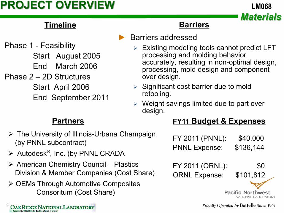
Barriers addressed Existing modeling tools cannot predict LFT
processing and molding behavior accurately, resulting in non-optimal design, processing, mold design and component over design.
Significant cost barrier due to mold retooling.
Weight savings limited due to part over design.
Timeline Barriers
The University of Illinois-Urbana Champaign (by PNNL subcontract)
Autodesk®, Inc. (by PNNL CRADA American Chemistry Council – Plastics
Division & Member Companies (Cost Share) OEMs Through Automotive Composites Consoritum (Cost Share)
Partners FY11 Budget & Expenses FY 2011 (PNNL): $40,000 PNNL Expense: $136,144 FY 2011 (ORNL): $0 ORNL Expense: $101,812
LM068 Materials
Phase 1 - Feasibility Start August 2005 End March 2006 Phase 2 – 2D Structures Start April 2006 End September 2011

Outline
Project Objective and Goals Objective, gap and project status Technical relevance
LFT Microstructural Aspects Difference between long and short fiber thermoplastics
Results and Discussion Process-property prediction Validation – 15% match with experimental results Collaborations Proposed future work
Summary Accomplishments and gaps
Key Publications
3
Materials LM068

4
Objectives
Develop Predictive Tools to enable the optimum design of lightweight automotive structures using injection-molded long-fiber thermoplastics
Technology Gap: Existing modeling tools cannot predict LFT processing and molding behavior accurately, resulting in non-optimal design, processing, mold design and component over design
Approach: Knowing the initial fiber length, concentration and other input
parameters going into the mold 1. Be able to first predict the final fiber orientation and length distributions in
the injection-molded part by process modeling 2. Then use predicted fiber orientation and lengths to predict the mechanical
properties in any given location and in any direction. 3. Then use that in a feedback loop to allow for mold design and control of
input parameters to obtain properties where desired. Phase 1 – Feasibility Phase 2 – Two dimension part (plaques)
Materials LM068
Project Status
5
Phase 1 – Feasibility assessment (09/01/2005 to 03/31/2006) Phase 2a – Development of new models and experimental methods
(04/01/2006 to 09/30/2009) Phase 2b – Validation on large plaques (10/01/2009 to 9/30/2011)
Project brings together: PNNL,ORNL, University of Illinois, Autodesk, Inc., American Chemistry Council – Plastics Division, OEM participants, and material suppliers (SABIC-IP, Ticona, DuPont™, DOW, etc.)
Materials LM068
Technical Relevance
6
Current automobiles contain 330 lb. of polymer and polymer composites per vehicle and injection molded thermoplastics comprise significant percentage of the per-vehicle total of polymers and polymer composites
Injection molding is cost-effective – parts with complex geometry can be made:
Inject ---> Demold ---> Part LFT automotive use by applications:
Front End Modules (17%) Instrument Panel Carriers (16%) Underbody Shields (13%) Door Modules (8%)
Existing modeling tools cannot predict LFT processing, molding behavior and properties accurately, resulting in over design New process and property prediction models have been developed using data from six molding trials (Delphi, RTP, DuPont, SABIC-IP, GM, and Injection Technologies)
Materials LM068
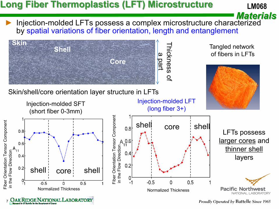
Long Fiber Thermoplastics (LFT) Microstructure
7
Skin Shell
Core
Skin/shell/core orientation layer structure in LFTs
Thickness of a part
core
shell core shell
shell shell
Injection-molded SFT (short fiber 0-3mm)
LFTs possess larger cores and
thinner shell layers
Injection-molded LFT (long fiber 3+)
Injection-molded LFTs possess a complex microstructure characterized by spatial variations of fiber orientation, length and entanglement
Tangled network of fibers in LFTs
Normalized Thickness Normalized Thickness
Materials LM068
Fibe
r Orie
ntat
ion
Tens
or C
ompo
nent
in
the
Flow
Dire
ctio
n
Fibe
r Orie
ntat
ion
Tens
or C
ompo
nent
in
the
Flow
Dire
ctio
n

8
An Integrated Approach Linking Process to Structural Modeling with Experimental Verifications
LFTs for structural and semi-structural applications
Process simulations using - A new fiber orientation model - A fiber length attrition model
Prediction of the composite microstructure
Model performs homogenization (EMTA): - Elastic properties - Coefficients of thermal expansion
Model is implemented in ABAQUS (EMTA-NLA): - Elastic-plastic analysis and strength prediction - Creep analysis - Damage and fatigue damage analyses - Impact analysis
Modeling (PNNL) EXPERIMENTS (ORNL) Microstructural characterizations - Fiber length distribution - Fiber orientation distribution - Fiber dispersion - Fiber/matrix debonding and other microdefects Mechanical testing - Quasi-static and fatigue tests - Creep and impact tests
Provide data to validate models
Creation of a composite part through simulations Univ. Illinois/PNNL/Autodesk
Materials
LM068
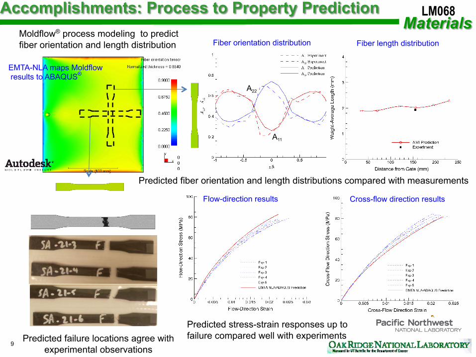
A11
A22
Fiber orientation distribution
9 Predicted failure locations agree with
experimental observations
Moldflow® process modeling to predict fiber orientation and length distribution
EMTA-NLA maps Moldflow results to ABAQUS®
Fiber length distribution
Predicted stress-strain responses up to failure compared well with experiments
Predicted fiber orientation and length distributions compared with measurements
Flow-direction results Cross-flow direction results
LM068

! " Metrics: Predictions of fiber orientation and length distributions are within 15% of experimental measurements ! " Performed with one set of material
parameters (no modification for gating, fill speed etc.)
! " Validated for all eight molding conditions of ACC molding trial
! " Three locations at each plaque (near gate, mid-flow, and end-of-flow)
10
Local comparison of predictions (solid line) with experiments (dashed line)
Global flow, orientation & fiber length prediction
in the part
Nor
mal
ized
Por
tion
of
Fibe
r Orie
ntat
ion
Prediction – Parallel to Flow Direction Prediction – Perpendicular to Flow Direction Measured – Parallel to Flow Direction Prediction – Perpendicular to Flow Direction
Normalized Thickness
LM068
-" Average mismatch of 7.7% for fiber orientation
-" Fiber orientation match within 15% target for 21/24 cases
-" Fiber length match within 15% target for 15/24 cases
11
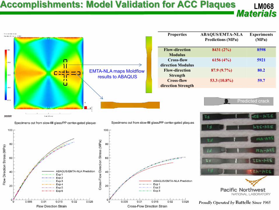
EMTA-NLA maps Moldflow results to ABAQUS
Properties ABAQUS/EMTA-NLA Predictions (MPa)
Experiments (MPa)
Flow-direction Modulus
8431 (2%) 8598
Cross-flow direction Modulus
6156 (4%) 5921
Flow-direction Strength
87.9 (9.7%) 80.2
Cross-flow direction Strength
53.3 (10.8%) 59.7
Predicted crack
Accomplishments: Model Validation for ACC Plaques Materials
LM068

Partners: University of Illinois at Urbana-Champaign subcontracted by PNNL (Prof. CL Tucker III) developed fiber orientation and length models for LFTs – provided consultant services to PNNL Autodesk, Inc. had CRADAs with PNNL to implement new process models for LFTs in Autodesk® Moldflow® Insight research versions and delivered these versions to PNNL for testing and validation – performed rheological measurements for LFTs for the project American Chemistry Council – Plastics Division and their members provided pellet materials for molding trials - consultant services and project reviews OEMs through the Automotive Composite Consortium provided molding trials, consultant services, and project reviews
Technology transfer: Results were transferred through model implementations in finite element packages (Autodesk® Moldflow® Insight and ABAQUS®) and through journal and conferences articles publications, and reports
12
LM068 Collaborations Materials

Consider a three-dimensional (3-D) complex LFT part possessing 3-D features representative of real-world automotive structures using LFTs Validate new process models for fiber orientation and length distributions for the complex part Validate the basic property prediction models (stiffness, local stress-strain responses, damage accumulations) for the complex part
13
LM068 Proposed Future Work Materials

14
Key accomplishments to date: Developed a fiber orientation model Developed a fiber attrition model for fiber length distribution in mold Fiber orientation and length models implemented in Moldflow research versions Developed models for predicting thermoelastic properties, elastic-plastic, damage, and creep behavior Integrated Moldflow’s process modeling to ABAQUS Developed characterization tools for determining microstructural features (fiber orientation & length distributions, etc.) Developed of LFT property database, including linear and non-linear properties Developed novel testing methods to determine fiber location, size and orientation Validated against 6 molding trials
Gaps: Tools are yet to be validated on complex 3-dimensional parts Molders are continually challenged to produce parts with long fibers 3-D Moldflow model requires additional work for refinement
Summary of Accomplishments and Gaps Materials
LM068