engineering mechanics page no 1. force and moment systems 1.1. force 01 1.2. moment of a force 01...
TRANSCRIPT

ENGINEERING
MECHANICS
For MECHANICAL ENGINEERING
CIVIL ENGINEERING

SYLLABUS Free body Diagrams and Equilibrium; Trusses and Frames; Virtual work; Kinematics and Dynamics of Particles and of Rigid bodies in Plane motion, including impulse and Momentum (linear and angular) and Energy formulations; Impact.
ANALYSIS OF GATE PAPERS Exam Year 1 Mark Ques. 2 Mark Ques. Total
2003 5 - 5
2004 - 3 6
2005 2 4 10
2006 - 2 4
2007 1 1 3
2008 1 2 5
2009 1 1 3
2010 - - -
2011 1 2 5
2012 2 3 8
2013 - 1 2
2014 Set-1 1 2 5
2014 Set-2 1 2 5
2014 Set-3 1 3 7
2014 Set-4 - 4 8
2015 Set-1 3 4 11
2015 Set-2 1 2 5
2015 Set-3 2 3 8
2016 Set-1 2 2 6
2016 Set-2 1 3 7
2016 Set-3 2 3 8
2017 1 2 5
ENGINEERING MECHANICS

Topics Page No
1. FORCE AND MOMENT SYSTEMS
1.1. Force 01 1.2. Moment of a Force 01 1.3. Equivalent System of a Force 03 1.4. Single Resultant Force 03
2. EQUILIBRIUM OF FORCE SYSTEMS
2.1. Equilibrium of Rigid Bodies 05 2.2 Equilibrium of Three Coplanar Forces 06
3. STRUCTURAL ANALYSIS
3.1. Trusses and Frames 09 3.2. Assumptions 09 3.3 Method of Joints 09 3.3 Zero-Force Members 10 3.5. Method of Sections 10
4. KINEMATICS & DYNAMICS OF PARTICLES & RIGID BODIES INPLANE MOTION
4.1. Rectilinear kinematics 14 4.2. Angular Motion 15 4.3. Motion Under Gravity 15 4.4. Dependent Motion of Particles 16 4.5. Newton's Laws of Motion 16 4.6. D'alembert's Principle 17
5. FRICTION
19 19 19
5.1. Frictional force 5.2. Co-efficient of friction 5.3. Laws of friction 5.4. Angle of Friction, Angle of Repose and Cone of Friction 19
6. WORK AND ENERGY PRINCIPLE
6.1. Energy 23 6.2. Modes of Mechanical Energy 23
CONTENTS

6.3. Principle of Work and Energy 24 6.4. Principle of Conservation of Energy 24
7. IMPULSE AND MOMENTUM
7.1. Linear Momentum 25 7.2. Angular Momentum 25 7.3. Impulse—Momentum Principle 25 7.4. Law of Restitution 25
8. PRINCIPLE OF VIRTUAL WORK 28
9. GATE QUESTIONS 30
10. ASSIGNMENT QUESTIONS 63

1.1. Force
Force is a vector quantity which tends to change the state of a body. It means force is capable to bring a static body into motion or a moving body into static position. The study of mechanics encounters various types of force systems. The forces meeting at one point constitute a concurrent force system. The forces lying in one plane constitute a coplanar force system. The SI unit of force is Newton (N), defined as the force acting on mass of 1 kg which produces an acceleration of 1 m/s2.
(i) Characteristics of a Force
Let a force F
acts on a rigid body placed on a rough horizontal plane. Depending upon
the magnitude of F
, the body can start moving in a straight line, if the line of
action of F
passes through the center of gravity of the body. This motion is called translation. If line of action does not pass through the center of gravity of the body,the force will also result into rotation of the body. Thus, a force is characterized by its magnitude, line of action, direction and point of application.
(ii) Resolutions of a Force Force is a vector quantity, therefore, has its resolved components in given directions, which are called resolutions. Engineering problems frequently need resolution of a force in orthogonal directions. Consider a
force F
in a x-y plane at an angle θ with the x-axis
Figure : Resolution of a force
Magnitudes of the resolved parts of force F along x and y directions are the given by Fx = F cosθ
yF Fcos2
Thus, the resolved part of a given force in a given direction is equal to the magnitude of the force multiplied with the cosine of the angle between the line of action of the force and the direction. Using the resolved parts, a force can be presented in vector form:
x yF F i F j
where is i and j are the unit vectors in x
and y directions, respectively. Magnitude of
force F
can be found as 2 2
x yF F F
The concept of resolved components is used to add two or more forces by summing their x and y components:
x xR Fy yR F
where Rx and Ry are the resolved components of the resultant force expressed as
x yR R i R j
1.2. Moment of a Force
(i) Definition Moment of a force about a point or axis is the measure of the tendency of the force to cause a body to rotate about the point or axis. It is quantified by the product of the force and the perpendicular distance of its line of action from the point. This perpendicular distance is called arm of the moment.
Consider a force F
acting on a rigid point. Moment of this force can be determined
about a point O situated at distance r
from line of action.
1 FORCE AND MOMENT SYSTEMS
© Copyright Reserved by Inspiring Creativity & Endeavour Gate Institute. No part of this material should be copied or reproduced without permission. 1
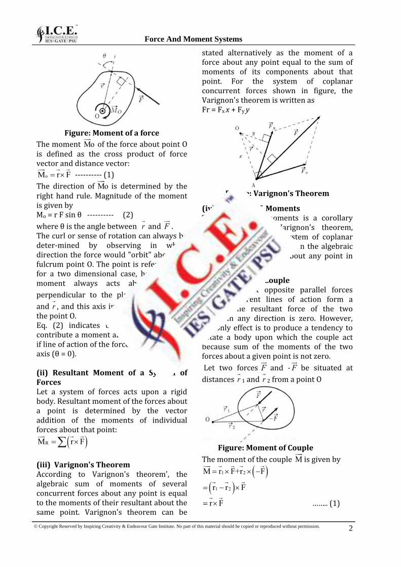
Figure: Moment of a force
The moment Mo
of the force about point O is defined as the cross product of force vector and distance vector:
oM r F
---------- (1)
The direction of Mo
is determined by the right hand rule. Magnitude of the moment is given by Mo = r F sin θ ---------- (2)
where θ is the angle between r
and F
. The curl or sense of rotation can always be deter-mined by observing in which direction the force would "orbit" about the fulcrum point O. The point is referred only for a two dimensional case, however, the moment always acts about an axis
perpendicular to the plane containing F
and r
, and this axis intersects the plane at the point O. Eq. (2) indicates that a force will not contribute a moment about a specified axis if line of action of the force is parallel to the axis (θ = 0). (ii) Resultant Moment of a System of Forces Let a system of forces acts upon a rigid body. Resultant moment of the forces about a point is determined by the vector addition of the moments of individual forces about that point:
RM r F
(iii) Varignon's Theorem According to Varignon's theorem', the algebraic sum of moments of several concurrent forces about any point is equal to the moments of their resultant about the same point. Varignon's theorem can be
stated alternatively as the moment of a force about any point equal to the sum of moments of its components about that point. For the system of coplanar concurrent forces shown in figure, the Varignon's theorem is written as Fr = Fx x + Fy y
Figure: Varignon's Theorem
(iv) Principle of Moments The principle of moments is a corollary derived from the Varignon's theorem, which states that if a system of coplanar forces is in equilibrium, then the algebraic sum of their moments about any point in their plane is zero.
(v) Moment of a Couple Two equal but opposite parallel forces having different lines of action form a couple. The resultant force of the two forces in any direction is zero. However, the only effect is to produce a tendency to rotate a body upon which the couple act because sum of the moments of the two forces about a given point is not zero.
Let two forces F
and -F
be situated at
distances r
1 and r
2 from a point O
Figure: Moment of Couple
The moment of the couple M
is given by
1 2M r F+r F
1 2r r F
r F
…….. (1)
© Copyright Reserved by Inspiring Creativity & Endeavour Gate Institute. No part of this material should be copied or reproduced without permission.
Force And Moment Systems
2
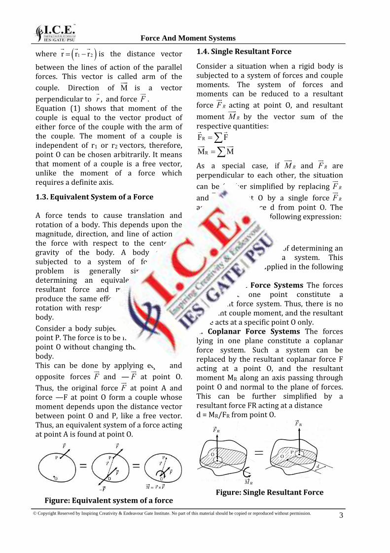
where 1 2r r r
is the distance vector
between the lines of action of the parallel forces. This vector is called arm of the
couple. Direction of M
is a vector
perpendicular to r
, and force F
. Equation (1) shows that moment of the couple is equal to the vector product of either force of the couple with the arm of the couple. The moment of a couple is independent of r1 or r2 vectors, therefore, point O can be chosen arbitrarily. It means that moment of a couple is a free vector, unlike the moment of a force which requires a definite axis.
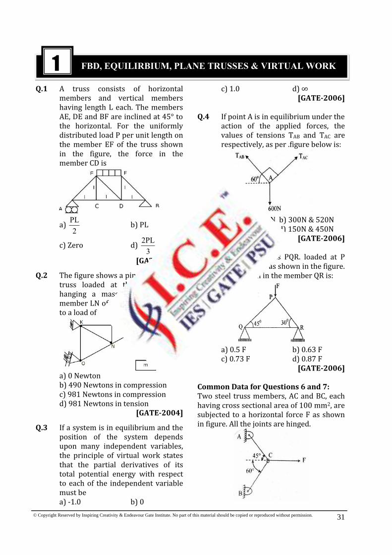
1.3. Equivalent System of a Force
A force tends to cause translation and rotation of a body. This depends upon the magnitude, direction, and line of action of the force with respect to the center of gravity of the body. A body can be subjected to a system of forces. The problem is generally simplified by determining an equivalent system of resultant force and moment that can produce the same effect of translation and rotation with respect to any point on the body.
Consider a body subjected to a force F
at point P. The force is to be moved to another point O without changing the effect on the body. This can be done by applying equal and
opposite forces F
and — F
at point O.
Thus, the original force F
at point A and force —F at point O form a couple whose moment depends upon the distance vector between point O and P, like a free vector. Thus, an equivalent system of a force acting at point A is found at point O.
Figure: Equivalent system of a force
1.4. Single Resultant Force
Consider a situation when a rigid body is subjected to a system of forces and couple moments. The system of forces and moments can be reduced to a resultant
force RF
acting at point O, and resultant
moment RM
by the vector sum of the respective quantities:
RF F
RM M
As a special case, if RM
and RF
are perpendicular to each other, the situation
can be further simplified by replacing RF
and RM
at point O by a single force RF
acting at a distance d from point O. The distance d is given by following expression:
R
R
Md
F
This effect is the reverse of determining an equivalent force of a system. This observation can be applied in the following special cases: 1. Concurrent Force Systems The forces meeting at one point constitute a concurrent force system. Thus, there is no resultant couple moment, and the resultant force acts at a specific point O only. 2. Coplanar Force Systems The forces lying in one plane constitute a coplanar force system. Such a system can be replaced by the resultant coplanar force F acting at a point O, and the resultant moment MR along an axis passing through point O and normal to the plane of forces. This can be further simplified by a resultant force FR acting at a distance d = MR/FR from point O.
Figure: Single Resultant Force
© Copyright Reserved by Inspiring Creativity & Endeavour Gate Institute. No part of this material should be copied or reproduced without permission.
Force And Moment Systems
3

Example: A roller of radius r = 300 mm and weight 2000 N is to be pulled over a curb of height 150 mm by a horizontal force P applied to the end of a string wound tightly around the circumference of the roller. Find the magnitude of P required to start the roller move over the curb. What is the least pull P through the centre of the wheel to just turn the roller over the curb?
Solution : When the roller is about to turn over the curb, the contact with the floor is lost and hence there is no reaction from the floor. The reaction R from the curb must pass through the intersection of P and the line of action of self weight, since the body is in equilibrium under the action of only three forces all the three forces must be concurrent. From diagram
OC (300 150) 1cos
AO 300 2
60
Now in ∆AOB,∠OAB = ∠OBA Since, OA = OB
OAB OBA 2 OBA 60
OBA 30 i.e.,the reaction makes 30° with the vertical Apply Fx = 0
P – R sin30° = 0
P = 2309.40 × sin30° P = 1154.70N
© Copyright Reserved by Inspiring Creativity & Endeavour Gate Institute. No part of this material should be copied or reproduced without permission.
Force And Moment Systems
4

Topics Page No
1. FBD, EQUILIRBIUM, PLANE TRUSSES AND VIRTUAL WORK 31
2. TRANSLATION AND ROTATION 40
3. FRICTION 46
4. IMPULSE, MOMENTUM, IMPACTS AND WORK-ENERGY 52
5. PLANE MOTION 59
GATE QUESTIONS
30
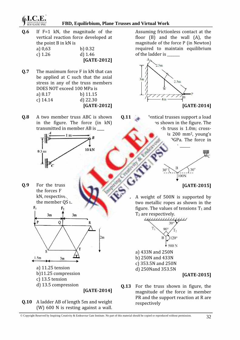
Q.1 A truss consists of horizontal members and vertical members having length L each. The members AE, DE and BF are inclined at 45° to the horizontal. For the uniformly distributed load P per unit length on the member EF of the truss shown in the figure, the force in the member CD is
a) PL
2b) PL
c) Zero d) 2PL
3
[GATE-2003]
Q.2 The figure shows a pin-jointed plane truss loaded at the point M by hanging a mass of 100 kg. The member LN of the truss is subjected to a load of
a) 0 Newtonb) 490 Newtons in compressionc) 981 Newtons in compressiond) 981 Newtons in tension
[GATE-2004]
Q.3 If a system is in equilibrium and the position of the system depends upon many independent variables, the principle of virtual work states that the partial derivatives of its total potential energy with respect to each of the independent variable must be a) -1.0 b) 0
c) 1.0 d) ∞[GATE-2006]
Q.4 If point A is in equilibrium under the action of the applied forces, the values of tensions TAB and TAC are respectively, as per .figure below is:
a) 520N & 300N b) 300N & 520Nc) 450N & 150N d) 150N & 450N
[GATE-2006]
Q.5 Consider a. truss PQR. loaded at P with a force F as shown in the figure. The tension in the member QR is:
a) 0.5 F b) 0.63 Fc) 0.73 F d) 0.87 F
[GATE-2006]
Common Data for Questions 6 and 7: Two steel truss members, AC and BC, each having cross sectional area of 100 mm2, are subjected to a horizontal force F as shown in figure. All the joints are hinged.
1 FBD, EQUILIRBIUM, PLANE TRUSSES & VIRTUAL WORK
© Copyright Reserved by Inspiring Creativity & Endeavour Gate Institute. No part of this material should be copied or reproduced without permission. 31
Q.6 If F=1 kN, the magnitude of the vertical reaction force developed at the point B in kN is
a) 0,63 b) 0.32 c) 1.26 d) 1.46
[GATE-2012]
Q.7 The maximum force F in kN that can be applied at C such that the axial stress in any of the truss members DOES NOT exceed 100 MPa is a) 8.17 b) 11.15 c) 14.14 d) 22.30
[GATE-2012]
Q.8 A two member truss ABC is shown in the figure. The force (in kN) transmitted in member AB is ____
[GATE-2014]
Q.9 For the truss shown in the figure,
the forces F1 and F2 are 9 kN and 3 kN, respectively. The force (in kN) in the member QS is
a) 11.25 tension
b)11.25 compression c) 13.5 tension d) 13.5 compression
[GATE-2014] Q.10 A ladder AB of length 5m and weight (W) 600 N is resting against a wall.
Assuming frictionless contact at the floor (B) and the wall (A), the magnitude of the force P (in Newton) required to maintain equilibrium of the ladder is _______
[GATE-2014]
Q.11 Two identical trusses support a load of 100 N as shown in the figure. The length of each truss is 1.0m; cross- sectional area is 200 mm2, young’s modulus E = 200GPa. The force in the truss AB (in N) is ______
[GATE-2015]
Q.12 A weight of 500N is supported by two metallic ropes as shown in the figure. The values of tensions T1 and T2 are respectively.
a) 433N and 250N b) 250N and 433N c) 353.5N and 250N d) 250Nand 353.5N
[GATE-2015] Q.13 For the truss shown in figure, the magnitude of the force in member PR and the support reaction at R are respectively
© Copyright Reserved by Inspiring Creativity & Endeavour Gate Institute. No part of this material should be copied or reproduced without permission.
FBD, Equilirbium, Plane Trusses and Virtual Work
32

Q.1 (a)
A BR R Pl
Taking moment about A
BPl(l l / 2) R 3l
B
PlR
2
A
PlR
2
Joint A
Now at joint A
VF 0
EA
PlF sin 45
2
EA
PlF
2
AC EAF F cos45
AC
Pl 1F
2 2
AC
PlF
2
At joint C
CA CD
PlF F
2 CEF 0
Q.2 (a)
HF 0 & VF 0At joint “L”
LK LM HF F 0 F 0
LN VF 0 F 0 Hence no force is acting on the truss number LN.
Q.3 (b) If any system is in equilibrium and subjected to many independent variables, partial derivates of its total potential energy with respect to each of the independent variable must be zero.
Q.4 (a)
By lami’s theorem
ACABTT 600
sin120 sin150 sin90
ABT 600sin120
519.61 520N And ACT 600sin150 300N
Q.5 (b)
EXPLANATIONS
© Copyright Reserved by Inspiring Creativity & Endeavour Gate Institute. No part of this material should be copied or reproduced without permission. 35
xtan 30
b
xb 1.732x
tan 30
RF x V 2.732x
RV 0.366F
QV F 0.366F 0.634F
FBD of joint Q
Let force in the member PQ is
PQF
PQ QF sin 45 V
PQF sin 45 0.634F
Force in member QR
QR PQF F cos45 0.634F
Q.6 (a)
Using Lame’s theorem
1 2T T F
sin120 sin135 sin105
1T 0.8965F
2T 0.732F
Vertical reaction at B,
B 2R T cos30 0.732cos30
BR 0.634kN
Q.7 (b)
Maximum force = 0.8965 F
Max stress 0.8965F
100MPa100
0.8965 F
100100
F 11.154kN
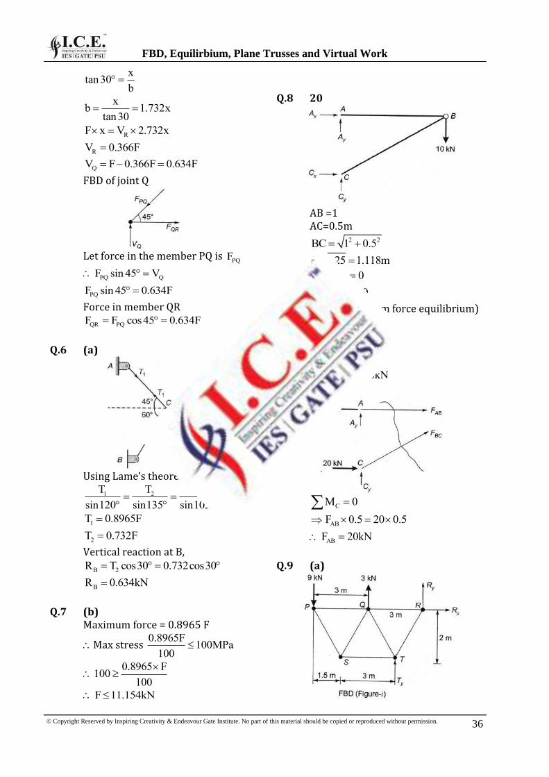
Q.8 20
AB =1 AC=0.5m
2 2BC 1 0.5
1.25 1.118m
x xA C 0
y yA C 10
(From force equilibrium)
AM 0
xC 0.5 10 1
Or xC 20kN
And xA 20kN
CM 0
ABF 0.5 20 0.5
ABF 20kN
Q.9 (a)
© Copyright Reserved by Inspiring Creativity & Endeavour Gate Institute. No part of this material should be copied or reproduced without permission.
FBD, Equilirbium, Plane Trusses and Virtual Work
36

Q.1 Two non-collinear parallel equal forces acting in opposite direction a) Balance each otherb) Constitute a momentc) Constitute a coupled) Constitute a moment of couple
Q.2 Forces are called coplanar when all of them acting on body lie in ` a) One pointb) One planec) Different planesd) Perpendicular planes
Q.3 Varignon's theorem of moments states that if a number of coplanar forces acting on a particle are in equilibrium, then a) Their algebraic sum is zerob) Their lines of action are at equal
distancesc) The algebraic sum of their
moments about any point intheir plane is zero
d) The algebraic sum of theirmoments about any point isequal to the moment of theirresultant force about the samepoint.
Q.4 The resultant of two forces P and Q (such that P > Q) acting along the same straight line, but in opposite direction, is given by a)P + Q b) P - Qc) P / Q d) Q / P
Q.5 If a number of forces are acting at a point, their resultant is given by a) (ΣV)2 + (ΣH)2
b) 2 2
V H c) (ΣV)2 + (ΣH)2 + 2(ΣV)( Σ H)
d) 2
V H 2 2 V H
Q.6 The system of forces is equal to two mutual perpendicular forces namely ∑X and ∑Y then the inclination of resultant R with X-axis θ given by
a) 1an Y/T X
b) 1 22XTan Y c) 1 2 2Xa YT n d) 1 Xan /T Y
Q.7 When a system of forces in a plane form a closed polygon the system is called in a) Equilibrium b) Non-equilibriumc) Stable d) Unstable
Q.8 A tripod carrying a camera is an example of force system representing a) Collinear concurrent forcesb) Coplanar concurrent forcesc) Non coplanar concurrent forcesd)Non-coplanar non-concurrent forces
Q.9 According to principle of transmissibility of forces, the effect of a force upon a body is: a) Maximum when it acts at the
centre of gravity of a bodyb) Different at different points in its
line of actionc) Same at every point in its line of
actiond) Minimum when it acts at the C.G.
of the body
Q.10 The resultant of two equal forces of magnitude P act at an angle α, will be: a) 2P sin(α/2) b)2Pcos(α /2)c) 2P tan(α /2) d) None of the above
Q.11 Law of parallelogram of forces states that if two forces acting on a particle are represented in magnitude and direction by two sides of the
ASSIGNMENT QUESTIONS
© Copyright Reserved by Inspiring Creativity & Endeavour Gate Institute. No part of this material should be copied or reproduced without permission. 63

parallelogram then their resultant is given by a) Sum of two forces b) Product of two forces c) Diagonal of the parallelogram d) None of the above
Q.12 A number of forces acting at a point
will be in equilibrium, if a) All the forces are equally
inclined b) Sum of all the forces is zero in
vertical and horizontal direction c) Sum of resolved parts in the
vertical direction is zero (i.e V = 0 )
d) None of these
Q.13 The force induced in the string AB due to the load W, as shown in the below figure is:
a) W sin θ b) W cos θ c) W sec θ d) W cosec θ
Q.14 The figure below shows the three coplanar forces P, Q and R acting, at a point 0. if these forces are in equilibrium, then
a) P Q R
sin sin sin
b) P Q R
sin sin sin
c) P Q R
sin sin sin
d) P Q R
sin sin sin
Q.15 A heavy ladder resting on floor and against a vertical wall may not be in equilibrium, if a) The floor is smooth, the wall is
rough b) The floor is rough, the wall is
smooth c) The floor and wall both are
smooth surfaces d) The floor and wall both are
rough surfaces
Q.16 Equilibrium signifies the condition where resultant of force system is: a) Positive b)Negative c) Zero d)None of the above
Q.17 If a body is in equilibrium under the action of three forces, the three forces must be a) Concurrent b) Parallel c) Either concurrent (or) parallel d) None of the above
Q.18 The angle of inclination of the plane at which the body begins to move down the plane, is equal to a) Angle of friction b) Angle of contact c) Angle of projection d) None of these
Q.19 The maximum frictional force, which comes into play, when a body just begins to slide over the surface of the other body, is known as a) Static friction b)Dynamic friction c) Limiting friction d) Coefficient of friction
Q.20 The static friction a) bears a constant ratio to the
normal reaction between the two surfaces
b) is independent of the area of contact, between the two surfaces
c) always acts in a direction, opposite to that in which the body tends to move
d) All of the above
© Copyright Reserved by Inspiring Creativity & Endeavour Gate Institute. No part of this material should be copied or reproduced without permission.
Assignment Questions
64
Q.24 (d)
Adopting method of joints
y BDF 0 F 0
Q.25 (b) j = 6 m = 11 m > 2j – 3 Therefore, Truss is redundant
Q.28 (c) 2u 2 49
t 10sg 9.81
Q.29 (d) V = t3 - t2 ; a = acceleration
2dva 3t 2t
dt
At, t = 3 sec 2 2a 3 3 2 3 27 6 21m / s
Q.30 (d)
V2 = u2 -2 gh 2 2
0max
v sinh
2g
2 2 2u sin 30 u
2g 8g
Q.31 (b)
210 usin t gt
2
2u sint
g
Q.32 (d) 2
2.1sec3
tt
Q.33 (c)
2 2
0 18rad / s ; 2rad / s ; 0
0 t 0 18 2t
t 9s
Q.34 (b) 2
Ta r 0.6 5 3m / s
Q.35. (a) Impulse = F ×dt = 14.45×2.56 = 36,99N-s
Q.36 (a) m1 = 4kg ; u1= 10m/s; m2 = 3kg ; u2 = 5m/s m1u1 + m2u2 = (m1+m2)V
4 10 3 5V 7.85m / s
(5 3)
Q.37 (b) m1 = 2kg, u1 = 10m/s; m2 = 2kg; u2 = 5m/s m1u1 + m2u2 = (m1+m2)V 2×10 = (2+2)× V V = 5m/s in the same direction.
Q.38 (a) Let P<Q⇒ Q = 40N α= 120° and θ = 90°
Q sinαtanθ
P Qcosα
Q sin120°°
P Qcta
os 0n90
12 °
10
2P Q
Q 4020NP
2 2
EXPLANATIONS
© Copyright Reserved by Inspiring Creativity & Endeavour Gate Institute. No part of this material should be copied or reproduced without permission. 75