engineering optical space with metamaterials: from ...shalaev/rome_2007/rome_tutorial.pdf · by...
TRANSCRIPT

Birck Nanotechnology Center
Vladimir M. ShalaevSchool of Electrical & Computer Engineering
Purdue University, USA
2007.10.26
Engineering Optical Space with Metamaterials: from Metamagnetics to Negative-Index and
Cloaking
Metamaterials’2007, RomeEuropean Doctoral School on Metamaterials

V. M. Shalaev, Oct. 26, 2007 2
Birck Nanotechnology Center
Invisibility: An Ancient Dream
Tarnhelm of invisibility(Norse mythology)
Perseus’ helmet(Greek mythology)
Ring of Gyges(“The Republic”, Plato)
The 12 Dancing Princesses(Brothers Grimm, Germany)
Cloaking devices(Star Trek, USA)
Harry Potter’s cloak(J. K. Rowling, UK)

V. M. Shalaev, Oct. 26, 2007 3
Birck Nanotechnology Center
Invisibility in Nature: Chameleon Camouflage

V. M. Shalaev, Oct. 26, 2007 4
Birck Nanotechnology Center
Invisibility by Transformation of Time-Space
Black hole
V. M. Shalaev, Oct. 26, 2007 5
Birck Nanotechnology Center
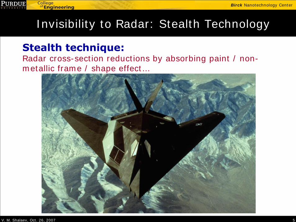
Invisibility to Radar: Stealth Technology
Stealth technique:Radar cross-section reductions by absorbing paint / non-metallic frame / shape effect…

V. M. Shalaev, Oct. 26, 2007 6
Birck Nanotechnology Center
Active Camouflage: Real time capture and re-display
Optical Camouflage, Tachi Lab, U. of Tokyo, Japan
Illustrating the concept: active capture and re-display, creates an "illusory transparency",

V. M. Shalaev, Oct. 26, 2007 7
Birck Nanotechnology Center
Cloaking ≠ Invisibility
• Cloaking is more than invisibility or camouflage– Camouflage: an adaptation to the surrounding environment.– Cloaking: No need to adapt to a particular environment, with the
ultimate goal of transparency — no scattering; no shade.
• Criteria for an ideal cloak– Macroscopic, not limit to subwavelength size or near field region.– Independent to the object to be cloaked.– Minimized absorption and scattering.– Passive– Broadband– …

V. M. Shalaev, Oct. 26, 2007 8
Birck Nanotechnology Center
Ideal Cloak: from fiction to fact?
The Invisible Man by H. G. Wells (1897)
“The invisible woman” in The Fantastic 4 by Lee & Kirby (1961)
Examples with scientific elements:

V. M. Shalaev, Oct. 26, 2007 9
Birck Nanotechnology Center
Ideal Cloak: from fiction to fact?
The Invisible Man by H. G. Wells (1897)
“The invisible woman” in The Fantastic 4 by Lee & Kirby (1961)
Examples with scientific elements:
"... it was an idea ... to lower the refractive index of a substance, solid or liquid, to that of air — so far as all practical purposes are concerned.” -- Chapter 19 "Certain First Principles"
"... she achieves these feats by bending all wavelengths of light in the vicinity around herself ... without causing any visible distortion.” -- Introduction from Wikipedia
Pendry et al.; Leonhard, Science, 2006(Earlier work: cloak of thermal conductivity by Greenleaf et al., 2003)

V. M. Shalaev, Oct. 26, 2007 10
Birck Nanotechnology Center
Transformation of Maxwell’s equations
Straight field line in Cartesian coordinate
Distorted field line in distorted coordinate
Spatial profile of ε & μ tensors determines the distortion of coordinate
Seeking for profile of ε & μ to make light avoid particular region in space — optical cloaking
Pendry et al., Science, 2006
V. M. Shalaev, Oct. 26, 2007 11
Birck Nanotechnology Center
Pendry et al., 2006
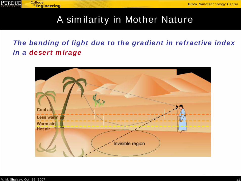
The bending of light due to the gradient in refractive index in a desert mirage
A similarity in Mother Nature

V. M. Shalaev, Oct. 26, 2007 12
Birck Nanotechnology Center
Cloaking in spherical system
The transformation in spherical system:
0 r b< < 'a r b< <
' ' 'b ar r ab
θ θ φ φ−= + = =
2
2
( )r r
b r ab a rbb abb a
θ θ
φ φ
ε μ
ε μ
ε μ
⎧ −= =⎪ −⎪
⎪ = =⎨ −⎪⎪ = =⎪ −⎩
Pendry et al., Science, 2006
Similar idea was proposed by Leonhardt, Science, 2006
a b
V. M. Shalaev, Oct. 26, 2007 13
Birck Nanotechnology Center
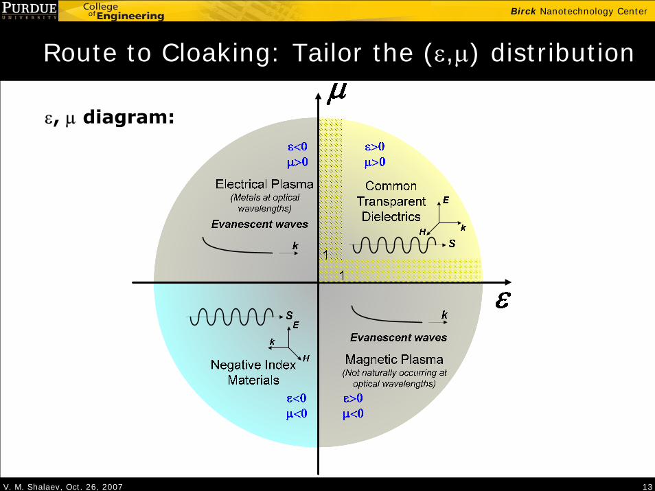
Route to Cloaking: Tailor the (ε,μ) distribution
ε, μ diagram:

V. M. Shalaev, Oct. 26, 2007 14
Birck Nanotechnology Center
Natural Optical Materials
Semiconductors
Crystals
WaterAir
metals

V. M. Shalaev, Oct. 26, 2007 15
Birck Nanotechnology Center
Metamaterials: Artificial media with designed (ε,μ)
--
Metamaterial is an arrangement of artificial structural elements, designed to achieve advantageous and unusual electromagnetic properties. ---Metamorphose
μετα = meta = beyond (Greek)
A natural material with its atoms
A metamatestructured “atoms”
rial with artificially

V. M. Shalaev, Oct. 26, 2007 16
Birck Nanotechnology Center
Electromagnetic properties v.s. characteristic sizes
0 1 aa<< .
Effective mediumdescription using
Maxwell equations with, , n, Z
a~Structure dominates.
Properties determinedby diffraction and
interference
a>>Properties described
using geometrical opticsand ray tracing
Example:Optical crystalsMetamaterials
Example:Photonics crystalsPhased array radarX-ray diffraction optics
Example:Lens systemShadows

V. M. Shalaev, Oct. 26, 2007 17
Birck Nanotechnology Center
Natural Crystals
... have lattice constants much smaller
than light wavelengths: a <<λ
… are treated as homogeneous media
with parameters ε, μ, n, Z (tensors in
anisotropic crystals)
… have a positive refractive index: n > 1
… show no magnetic response at optical
wavelengths: μ =1

V. M. Shalaev, Oct. 26, 2007 18
Birck Nanotechnology Center
Photonic crystals
... have lattice constants comparable
to light wavelengths: a ~ λ
… can be artificial or natural
… have properties governed by the diffraction of the periodic structures
… may exhibit a bandgap for photons
… typically are not well described
using effective parameters ε, μ, n, Z
… often behave like but they are nottrue metamaterials

V. M. Shalaev, Oct. 26, 2007 19
Birck Nanotechnology Center
Noble metal: ε < 1 in nature
500 1000 1500 2000-250
-200
-150
-100
-50
0
50
Wavelength (nm)
Per
mitt
ivity
of S
ilver
Re(ε), experimentIm(ε), experimentRe(ε), DrudeIm(ε), Drude
2
0( )( )
p
iω
ε ω εω ω
= −+ Γ
0 5.09.216
0.0212p eV
eV
εω
==
Γ =
Drude model for permittivity: Silver parameters:
Experimental data from Johnson & Christy, PRB, 1972

V. M. Shalaev, Oct. 26, 2007 20
Birck Nanotechnology Center
Electrical metamaterials:metal wires arrays with tunable plasma frequency
A periodic array of thin metal wires with r<<a<<λ acts as a low frequency plasma
The effective ε is described with modified ωp
Plasma frequency depends on geometry rather than on material properties
2
2 2 20
' " 1( / )
p
p
ii a r
ωε ε ε
ω ω ε ω π σ= + = −
+
Pendry, PRL (1996)
22
2
2ln( / )pc
a a rπω =

V. M. Shalaev, Oct. 26, 2007 21
Birck Nanotechnology Center
Metal-Dielectric Composites and Mixing Rules
( )1 1 2 2
1 2 1 2 2 1
c c
c c
ε ε ε
ε ε ε ε ε⊥
= +⎧⎪⎨
= +⎪⎩
( ) ( )( ) ( )
( ) ( )( ) ( )ωεωε
ωεωεωεωε
ωεωε
hi
hi
hMG
hMG f22 +
−=
+−
[ ]2
' "( 1) ( 1 )1
2( 1) ( 1) ( 1 ) 4( 1)
e e e
m d
m d m d
idp d dp
d dp d dp d
ε ε εε ε
ε ε ε ε
= +
− + − −⎧ ⎫⎪ ⎪= ⎨ ⎬− ± − + − − + −⎪ ⎪⎩ ⎭

V. M. Shalaev, Oct. 26, 2007 22
Birck Nanotechnology Center
Electromagnetic properties of metal wires
2 3/ 2 2 1/ 2 2 1/ 20 2( ) ( ) ( )i j k
ii j k
a a a dsq
s a s a s a∞
=+ + +∫
(1 ) /q qκ = −
(1 ) 0m eff d eff
m eff d eff
f fε ε ε ε
ε κε ε κε− −
+ − =+ +
{ }21 42eff m dε ε ε κε εκ
= ± + [( 1) 1] [ ( 1) ]m df fε κ ε κ κ ε= + − + − +
10-2
10-1
100
101
1020
0.2
0.4
0.6
0.8
1
Aspect ratio, α:1:1
Dep
olar
izat
ion
fact
or, p
Lorentz depolarization factor for a spheroid with aspect ratio α:1:1
p(1:1:1)=1/3
Depolarization factor:
Screening factor:
Clausius-Mossotti yields shape-dependent EMT:

V. M. Shalaev, Oct. 26, 2007 23
Birck Nanotechnology Center
Absence of Optical Magnetism in Nature
“… the magnetic permeability µ(ω) ceases to have any physical meaning at relatively low frequencies…there is certainly no meaning in using the magnetic susceptibility from optical frequencies onwards, and in discussion of such phenomena we must put µ=1.”
Landau and Lifshitz, ECM, Chapter 79.
Magnetic coupling to an atom: ~ 0/ 2B ee m c eaμ α= =
0eaElectric coupling to an atom: ~
(Bohr magneton)
Magnetic effect / electric effect ≈ α2 ≈ (1/137)2 < 10 -4
V. M. Shalaev, Oct. 26, 2007 24
Birck Nanotechnology Center
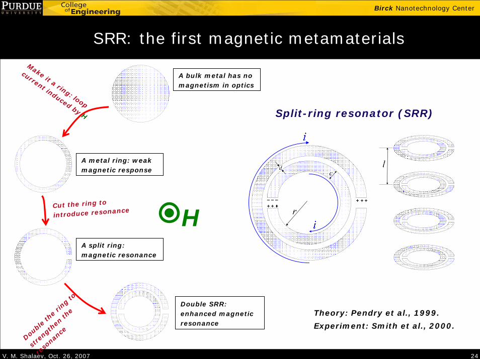
SRR: the first magnetic metamaterials
Theory: Pendry et al., 1999.
H
A bulk metal has no magnetism in optics
Make it a ring: loop
current induced by H
A metal ring: weak magnetic response
Cut the ring to
introduce resonance
A split ring: magnetic resonance
Double
the
ring to
stre
ngthen
the
reso
nance
Double SRR: enhanced magnetic resonance
Split-ring resonator (SRR)
Experiment: Smith et al., 2000.

V. M. Shalaev, Oct. 26, 2007 25
Birck Nanotechnology Center
Towards Optical Magnetic Metamaterials
Terahertz magnetism
A) Yen, et al. ~ 1THz (2-SRR) – 2004 Katsarakis, et al (SRR – 5 layers) - 2005
b) Zhang et al ~50THz (SRR+mirror) - 2005c) Linden, et al. 100THz (1-SRR) -2004d) Enkrich, et al. 200THz (u-shaped)-2005
2004-2007 years: from 10 GHz to 500 THZ

V. M. Shalaev, Oct. 26, 2007 26
Birck Nanotechnology Center
Limits of size scaling in SRRs
Direct scaling-down the SRR dimensions doesn’t help much…
total coil kineticL L L= +
Zhou et al, PRL (2005); Klein, et al., OL (2006)
coilL size∝1
kineticLsize
∝
totalC size∝
2
1 1 1( / ) ( ) .
restotal totalL C A size B size C size size const
ω ∝ = ∝× ⋅ + ⋅ ⋅ +
Saturation
Loss in metal gives kinetic inductance

V. M. Shalaev, Oct. 26, 2007 27
Birck Nanotechnology Center
Magnetic Metamaterial: Nanorod to Nanostrip
E
H
k
Dielectric
Metal
Nanorod pair Nanorod pair array Nanostrip pair
• Nanostrip pair has a much stronger magnetic response
Lagar’kov, Sarychev PRB (1996) - µ > 0 Podolskiy, Sarychev & Shalaev, JNOPM (2002) - µ < 0 & n < 0Kildishev et al, JOSA B (2006); Shvets et al JOSA (2006) – strip pairsSvirko, et al, APL (2001) - “crossed” rods for chirality

V. M. Shalaev, Oct. 26, 2007 28
Birck Nanotechnology Center
Visible magnetism: structure and geometries
35 40 2 bt nm d nm p w= = ≈
Purdue groupYuan, et al., Opt. Expr., 2007 – red lightCai, et al., Opt. Expr., 2007 – all the visible
Width varies from 50 nm to 127 nm

V. M. Shalaev, Oct. 26, 2007 29
Birck Nanotechnology Center
Negative Magnetic Response
EH
k

V. M. Shalaev, Oct. 26, 2007 30
Birck Nanotechnology Center
Width tunes resonance
Resonant TMTransmission
Non-resonant TETransmission
Resonant TMReflection
Non-resonant TEReflection
Sample # A B C D E F
Width w (nm) 50 69 83 98 118 127
Cai, et al., Opt. Expr., 15, 3333 (2007)
400 500 600 700 800 9000.00.10.20.30.40.50.60.70.80.9
Tran
smis
sion
Wavelength (nm)
A B C D E F
400 500 600 700 800 9000.00.10.20.30.40.50.60.70.80.9
Wavelength (nm)
A B C D E F
400 500 600 700 800 9000.00.10.20.30.40.50.60.70.80.9
Ref
lect
ion
Wavelength (nm)
A B C D E F
400 500 600 700 800 9000.00.10.20.30.40.50.60.70.80.9
Wavelength (nm)
A B C D E F
160 μm

V. M. Shalaev, Oct. 26, 2007 31
Birck Nanotechnology Center
Dependence of λm and μ′ on w
λm as a function of strip width “w”: experiment vs. theory
Negligible saturation effect on size-scaling (as opposed to SRRs)
50 60 70 80 90 100 110 120 130450
500
550
600
650
700
750
800 Experimental Analytical Permeability
Strip width, w (nm)
λ m (n
m)
-2.0
-1.5
-1.0
-0.5
0.0
0.5
1.0P
ermeability (μ')

V. M. Shalaev, Oct. 26, 2007 32
Birck Nanotechnology Center
Negative refractive index: A historical review
Sir Arthur Schuster Sir Horace Lamb
L. I. Mandel’stam
V. G. Veselago
Sir John Pendry
… energy can be carried forward at the group velocity but in a direction that is anti-parallel to the phase velocity…
Schuster, 1904
Negative refraction and backward propagation of waves
Mandel’stam, 1945
Left-handed materials: the electrodynamics of substances with simultaneously negative values of ε and μ
Veselago, 1968
Pendry, the one who whipped up the recent boom of NIM researches
Perfect lens (2000)EM cloaking (2006)

V. M. Shalaev, Oct. 26, 2007 33
Birck Nanotechnology Center
Metamaterials with Negative Refraction
Single-negative:n<0 when ε′ < 0 whereas μ′ > 0 (F is low)
Double-negative:n<0 with both ε′ < 0 and μ′ < 0 (F can be large)
n < 0, if ε′|μ| + μ′|ε| < 0
εμn
εμn
±=
=2
Refraction:
Figure of meritF = |n’|/n”
PIM
NIM

V. M. Shalaev, Oct. 26, 2007 34
Birck Nanotechnology Center
Negative index metamaterials
Negative electrical metamaterial + Negative magnetic metamaterial= Negative index metamaterial
+ =
Smith, et al., UCSD, PRL (2000)

V. M. Shalaev, Oct. 26, 2007 35
Birck Nanotechnology Center
The first NIM in microwave
Smith, et al., UCSD, PRL (2000)
Transmission properties of the structure
E,H ~ exp[in(ω/c)z]n = ±√(εμ)

V. M. Shalaev, Oct. 26, 2007 36
Birck Nanotechnology Center
Negative-index Material in Microwave
Smith, et al., UCSD, Science (2001)
2D waveguide 3D free space
The Boeing Cube
Parazzoli, et al., Boeing, PRL (2003)
NIM Teflon

V. M. Shalaev, Oct. 26, 2007 37
Birck Nanotechnology Center
Negative Index Design for Optical Frequencies
E
H
k
Dielectric
Metal
Nanostrip pair (TM)
μ < 0 (resonant)
Nanostrip pair (TE)
ε < 0 (non-resonant)
Fishnet
ε and μ < 0
S. Zhang, et al., PRL (2005)

V. M. Shalaev, Oct. 26, 2007 38
Birck Nanotechnology Center
A Negative-index Material close to the Visible
• E-beam lithography
• Period = 300 nm along both axis
• Average width of strips along H = 130 nm Average width of strips along E = 95 nm
H
E
Alumina
Silver
ITO300 nm
300 nm
Stacking:
10 nm of Al2O333 nm of Ag38 nm of Al2O333 nm of Ag10 nm of Al2O3
SEM image and primary polarization

V. M. Shalaev, Oct. 26, 2007 39
Birck Nanotechnology Center
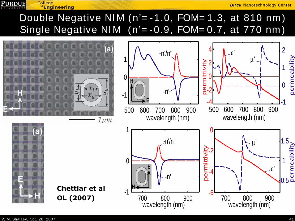
Solid line : Experimental
Spectra for Primary Polarization
• Magnetic resonance around λ = 800 nm
• Electric resonance around λ = 600 nm
U. K. Chettiar, et al., Optics Letters 32, 1671 (2007)
• Finite Elements
Dashed line: Simulated

V. M. Shalaev, Oct. 26, 2007 40
Birck Nanotechnology Center
Field Maps for Primary Polarization
Electrical Resonance, λ = 625 nm Magnetic Resonance, λ = 815 nm
E
H
k
V. M. Shalaev, Oct. 26, 2007 41
Birck Nanotechnology Center
Double Negative NIM (n’=-1.0, FOM=1.3, at 810 nm) Single Negative NIM (n’=-0.9, FOM=0.7, at 770 nm)
wavelength (nm)wavelength (nm)
pe
rme
ab
ility
pe
rmitt
ivity
500 600 700 800 900-1
0
1
2
-4-2
0
2
4μ'
ε'
500 600 700 800 900
-1
0
1-n'/n"
-n'E
H
pe
rme
ab
ility
pe
rmitt
ivity
μ'
ε'
wavelength (nm) wavelength (nm)
-n'/n"
-n'E
H
700 800 900-1
0
1
700 800 900
0.5
1
1.5
-6
-4
-2
0
Chettiar et alOL (2007)

V. M. Shalaev, Oct. 26, 2007 42
Birck Nanotechnology Center
Materials ready…
ε, μ diagram:

V. M. Shalaev, Oct. 26, 2007 43
Birck Nanotechnology Center
Gradient Metamaterial: A critical step
Negative index gradient lens
n = -2.7 on edge
n = -1.0 on center
D. R. Smith Group, PRE 2005; APL 2006

V. M. Shalaev, Oct. 26, 2007 44
Birck Nanotechnology Center
Back to Cloak: cylindrical system
The transformation in cylindrical system:
0 r b< < 'a r b< <
' ' 'b ar r a z zb
θ θ−= + = =
2
r r
z z
r arrr ab r ab a r
θ θ
ε μ
ε μ
ε μ
⎧ −= =⎪
⎪⎪
= =⎨ −⎪⎪ −⎛ ⎞= =⎪ ⎜ ⎟−⎝ ⎠⎩
Smith et al., arXiv, 2006

V. M. Shalaev, Oct. 26, 2007 45
Birck Nanotechnology Center
The transformation in cylindrical system:
0 r b< < 'a r b< <
' ' 'b ar r a z za
θ θ−= + = =
2
r r
z z
r arrr ab r ab a r
θ θ
ε μ
ε μ
ε μ
⎧ −= =⎪
⎪⎪
= =⎨ −⎪⎪ −⎛ ⎞= =⎪ ⎜ ⎟−⎝ ⎠⎩
2
z
r
b r ab a rrr ar ar
θ
ε
μ
μ
⎧ −⎛ ⎞=⎪ ⎜ ⎟−⎝ ⎠⎪⎪⎪ =⎨ −⎪
−⎪ =⎪⎪⎩
2
2
1
z
r
bb a
r ar
θ
ε
μ
μ
⎧ ⎛ ⎞=⎪ ⎜ ⎟−⎝ ⎠⎪⎪ =⎨⎪
−⎛ ⎞⎪ = ⎜ ⎟⎪ ⎝ ⎠⎩
TE incidence
To maintain the dispersion relation only
z
r z
constantconstant
θμ εμ ε
=⎧⎨ =⎩
Towards an experimental demonstration
Schurig et al., Science, 2006

V. M. Shalaev, Oct. 26, 2007 46
Birck Nanotechnology Center
The First Metamaterial Cloak
Duke group, 2006

V. M. Shalaev, Oct. 26, 2007 47
Birck Nanotechnology Center
Ideal case
Reduced parameter
Experimental data
Structure of the cloak
Experimental demonstration at microwave frequency
Schurig et al., Science, 2006
V. M. Shalaev, Oct. 26, 2007 48
Birck Nanotechnology Center
Movie: How it works
News release, Duke Univ., Oct. 2006

V. M. Shalaev, Oct. 26, 2007 49
Birck Nanotechnology Center
Nature Photonics (to be published)
Optical Cloaking with Metamaterials:Can Objects be Invisible in the Visible?
Cover article of Nature Photonics (April, 2007)

V. M. Shalaev, Oct. 26, 2007 50
Birck Nanotechnology Center
How about optical frequencies?
Scaling the microwave cloak design?Intrinsic limits to the scaling of SRR size
High loss in resonant structures
TM incidence
To maintain the dispersion relation
z
z r
constantconstant
θμ εμ ε
=⎧⎨ =⎩
2
, ,r r z zr a r b r ar r a b a rθ θε μ ε μ ε μ− −⎛ ⎞= = = = = = ⎜ ⎟− −⎝ ⎠
2
z
r
b r ab a rrr ar ar
θ
μ
ε
ε
⎧ −⎛ ⎞=⎪ ⎜ ⎟−⎝ ⎠⎪⎪⎪ =⎨ −⎪
−⎪ =⎪⎪⎩
2
2 2
1z
r
bb a
b r ab a r
θ
μ
ε
ε
⎧⎪ =⎪⎪⎪ ⎛ ⎞=⎨ ⎜ ⎟−⎝ ⎠⎪⎪ −⎛ ⎞ ⎛ ⎞⎪ = ⎜ ⎟ ⎜ ⎟−⎪ ⎝ ⎠ ⎝ ⎠⎩
A constant permittivity of a dielectric; 1θ
No magnetism required!
ε >
(for in-plane k)
Gradient in r direction only; εr changing from 0 to 1.
Cai, et al., Nature Photonics, 1, 224 (2007)
HE
k

V. M. Shalaev, Oct. 26, 2007 51
Birck Nanotechnology Center
Structure of the cloak: “Round brush”
metal needles embedded in dielectric host
Unit cell:
Flexible control of εr ;
Negligible perturbation in εθ
Cai, et al., Nature Photonics, 1, 224 (2007)

V. M. Shalaev, Oct. 26, 2007 52
Birck Nanotechnology Center
Cloaking performance: Field mapping movies
Example:Non-magnetic cloak @ 632.8nm
Cloak ONCloak OFF

V. M. Shalaev, Oct. 26, 2007 53
Birck Nanotechnology Center
Scattering issue in a non-magnetic cloak
Non-magnetic (linear) Cloak
Ideal Cloak
1zr b
r b
Zθ
με=
=
= =
Perfectly matched impedance results in zero scattering
1zr b
r b
aZ bθ
με=
=
= = −
Detrimental scattering due to impedance mismatch

V. M. Shalaev, Oct. 26, 2007 54
Birck Nanotechnology Center
Normalized scattered field

V. M. Shalaev, Oct. 26, 2007 55
Birck Nanotechnology Center
High-order transformations minimize scattering
Linear transformation
b ar r ab− ′= +
Cai, et al., App. Phys. Lett, 91, 111105 (2007)
Jacobian Matrix
Nonlinear transformation
( )r g r′= (0) ; ( ) ; ( ) 0g a g b b g r r′ ′= = ∂ ∂ >
ε And μ tensors for ideal cloak
( )( )( )
1
1
( )
( )
( )
r r
z z
r r g r r
r r g r r
r r g r r
θ θ
ε μ
ε μ
ε μ
−
−
⎧⎪ ′ ′ ′= = ∂ ∂⎪⎪⎪⎪⎪ ⎡ ⎤′ ′ ′= = ∂ ∂⎨ ⎢ ⎥⎣ ⎦⎪⎪⎪⎪ ⎡ ⎤′ ′ ′= = ∂ ∂⎪ ⎢ ⎥⎪ ⎣ ⎦⎩
Corresponding non-magnetic parameters ( )2 2
; ( ) ; 1r zr r g r rθε ε μ−⎡ ⎤′ ′ ′= = ∂ ∂ =⎢ ⎥⎣ ⎦
Set Z=1 at r=b to fix g(r′) ( ) 1r b zr br b
Z g r rθμ ε===
′ ′= = ∂ ∂ =
HE
k

V. M. Shalaev, Oct. 26, 2007 56
Birck Nanotechnology Center
Example: Optimized quadratic transformation
( ) 2( ) 1r g r a b p r b r a with p a b⎡ ⎤′ ′ ′= = − + − + =⎢ ⎥⎣ ⎦
A second-order transformation for non-magnetic cloak with minimized scattering

V. M. Shalaev, Oct. 26, 2007 57
Birck Nanotechnology Center
Transformation and impedance
0 1 2 3 40
1
2
3
4
r/a, old coordinates
r/a, n
ew c
oord
inat
es
0 1 2 3 40
0.5
1
1.5
r/a, new coordinates
impe
danc
e at
r=b
linearquadratic
b b

V. M. Shalaev, Oct. 26, 2007 58
Birck Nanotechnology Center
Reduced scattering from nonlinear cloak
Normalized scattered field

V. M. Shalaev, Oct. 26, 2007 59
Birck Nanotechnology Center
Suppression in both magnitude and directivity
Scattering radiation pattern
270°
90°
180° 0°
0.0 0.5 1.0
Ei
k
scatterer
linearquadratic
Birck Nanotechnology Center
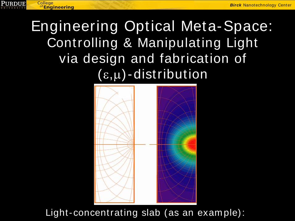
Engineering Optical Meta-Space:Controlling & Manipulating Light
via design and fabrication of (ε,μ)-distribution
Light-concentrating slab (as an example):
V. M. Shalaev, Oct. 26, 2007 61
Birck Nanotechnology Center
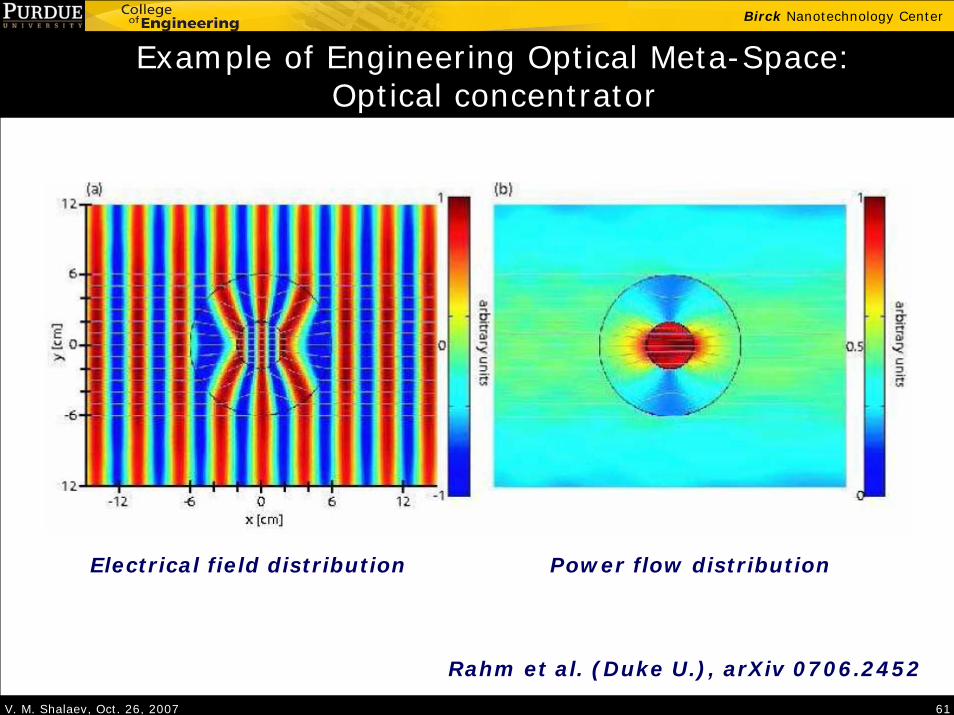
Example of Engineering Optical Meta-Space:Optical concentrator
Electrical field distribution Power flow distribution
Rahm et al. (Duke U.), arXiv 0706.2452
V. M. Shalaev, Oct. 26, 2007 62
Birck Nanotechnology Center
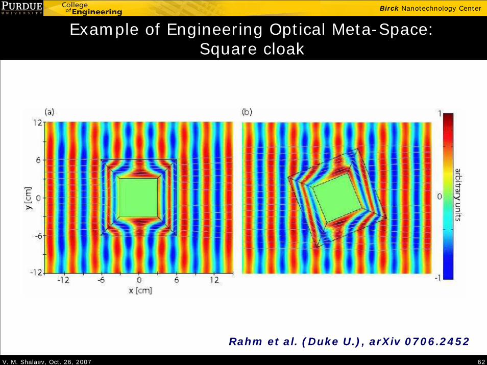
Example of Engineering Optical Meta-Space:Square cloak
Rahm et al. (Duke U.), arXiv 0706.2452