engineering operation & maintenance - turnkey pump...
TRANSCRIPT
WIL-11250-E-05TO REPLACE WIL-11250-E-04
W h e r e I n n o v a t i o n F l o w s
www.wildenpump.com
P800/PX800Advanced™ SeriesPlastic Pump
EOMEngineering
Operation &Maintenance

T A B L E O F C O N T E N T S
SECTION 1 CAUTIONS—READ FIRST! . . . . . . . . . . . . . . . . . . . . . . . . . . . . . . . . . . . . . . . . . . . . . .1
SECTION 2 WILDEN PUMP DESIGNATION SYSTEM . . . . . . . . . . . . . . . . . . . . . . . . . . . . . . . . .2
SECTION 3 HOW IT WORKS—PUMP & AIR DISTRIBUTION SYSTEM . . . . . . . . . . . . . . . .3
SECTION 4 DIMENSIONAL DRAWINGS . . . . . . . . . . . . . . . . . . . . . . . . . . . . . . . . . . . . . . . . . . . . .4
SECTION 5 PERFORMANCEA . P800 Performance Curves
Rubber-Fitted . . . . . . . . . . . . . . . . . . . . . . . . . . . . . . . . . . . . . . . . . . . . . . . . . . . . . . . .6TPE-Fitted . . . . . . . . . . . . . . . . . . . . . . . . . . . . . . . . . . . . . . . . . . . . . . . . . . . . . . . . . . .6Reduced-Stroke PTFE-Fitted . . . . . . . . . . . . . . . . . . . . . . . . . . . . . . . . . . . . . . . . . . . .7Full-Stroke PTFE-Fitted . . . . . . . . . . . . . . . . . . . . . . . . . . . . . . . . . . . . . . . . . . . . . . . .7Ultra-Flex™-Fitted . . . . . . . . . . . . . . . . . . . . . . . . . . . . . . . . . . . . . . . . . . . . . . . . . . . .8Suction-Lift Curve . . . . . . . . . . . . . . . . . . . . . . . . . . . . . . . . . . . . . . . . . . . . . . . . . . . .9
B . PX800 Performance Curves Operating Principle . . . . . . . . . . . . . . . . . . . . . . . . . . . . . . . . . . . . . . . . . . . . . . . . . . . .12 How to Use this EMS Curve . . . . . . . . . . . . . . . . . . . . . . . . . . . . . . . . . . . . . . . . . . . . .13 Performance Curves
Rubber-Fitted . . . . . . . . . . . . . . . . . . . . . . . . . . . . . . . . . . . . . . . . . . . . . . . . . . . .16TPE-Fitted . . . . . . . . . . . . . . . . . . . . . . . . . . . . . . . . . . . . . . . . . . . . . . . . . . . . . . .17Reduced-Stroke PTFE-Fitted . . . . . . . . . . . . . . . . . . . . . . . . . . . . . . . . . . . . . . . .18Full-Stroke PTFE-Fitted . . . . . . . . . . . . . . . . . . . . . . . . . . . . . . . . . . . . . . . . . . . . .19Ultra-Flex™-Fitted . . . . . . . . . . . . . . . . . . . . . . . . . . . . . . . . . . . . . . . . . . . . . . . . 20
Suction-Lift Curve . . . . . . . . . . . . . . . . . . . . . . . . . . . . . . . . . . . . . . . . . . . . . . . . . . .21
SECTION 6 SUGGESTED INSTALLATION, OPERATION & TROUBLESHOOTING . . . . . . .23
SECTION 7 DISASSEMBLY/REASSEMBLYPump Disassembly . . . . . . . . . . . . . . . . . . . . . . . . . . . . . . . . . . . . . . . . . . . . . . . . . . . . . . .25Pro-Flo® Air Valve / Center Section Disassembly . . . . . . . . . . . . . . . . . . . . . . . . . . . . . . .29Pro-Flo XTM Air Valve / Center Section Disassembly . . . . . . . . . . . . . . . . . . . . . . . . . . . .32Reassembly Hints & Tips . . . . . . . . . . . . . . . . . . . . . . . . . . . . . . . . . . . . . . . . . . . . . . . . . .34
SECTION 8 EXPLODED VIEW & PARTS LISTINGP800 PLASTIC P800 Full-Stroke PTFE-Fitted . . . . . . . . . . . . . . . . . . . . . . . . . . . . . . . . . . . . . . . . . . . .36 P800 Reduced-Stroke Ultra-Flex-Fitted . . . . . . . . . . . . . . . . . . . . . . . . . . . . . . . . . . . .38P800 PLASTIC PX800 Full-Stroke PTFE-Fitted . . . . . . . . . . . . . . . . . . . . . . . . . . . . . . . . . . . . . . . . . . .40 PX800 Reduced-Stroke Ultra-Flex-Fitted . . . . . . . . . . . . . . . . . . . . . . . . . . . . . . . . . . .42
SECTION 9 ELASTOMER OPTIONS . . . . . . . . . . . . . . . . . . . . . . . . . . . . . . . . . . . . . . . . . . . . . . . . .44
WIL-11250-E-05 1 WILDEN PUMP & ENGINEERING, LLC
CAUTION: Do not apply compressed air to the exhaust port — pump will not function.
CAUTION: Do not over-lubricate air supply — excess lubrication will reduce pump performance. Pump is pre-lubed.
TEMPERATURE LIMITS: Polypropylene 0°C to 79°C 32°F to 175°F PVDF –12°C to 107°C 10°F to 225°F PFA 7°C to 107°C 20°F to 225°F Neoprene –18°C to 93°C 0°F to 200°F Buna-N –12°C to 82°C 10°F to 180°F EPDM –51°C to 138°C –60°F to 280°F Viton® FKM –40°C to 177°C –40°F to 350°F Wil-Flex™ –40°C to 107°C –40°F to 225°F Saniflex™ –29°C to 104°C –20°F to 220°F Polyurethane –12°C to 66°C 10°F to 150°F Polytetrafluoroethylene (PTFE)1 4°C to 104°C 40°F to 220°F Nylon –18°C to 93°C 0°F to 200°F Acetal –29°C to 82°C –20°F to 180°F SIPD PTFE with Neoprene-backed 4°C to 104°C 40°F to 220°F SIPD PTFE with EPDM-backed –10°C to 137°C 14°F to 280°F Polyethylene 0°C to 70°C 32°F to 158°F Geolast® –40°C to 82°C –40°F to 180°F
NOTE: Not all materials are available for all models. Refer to Section 2 for material options for your pump.
CAUTION: When choosing pump materials, be sure to check the temperature limits for all wetted components. Example: Viton® has a maximum limit of 177°C (350°F) but polypropylene has a maximum limit of only 79°C (175°F).
CAUTION: Maximum temperature limits are based upon mechanical stress only. Certain chemicals will significantly reduce maximum safe operating temperatures. Consult Chemical Resistance Guide (E4) for chemical compatibility and temperature limits.
WARNING: Prevent static sparking. If static sparking occurs, fire or explosion could result.
CAUTION: Do not exceed 8.6 bar (125 psig) air supply pressure.
CAUTION: The process fluid and cleaning fluids must be chemically compatible with all wetted pump components. Consult Chemical Resistance Guide (E4).
CAUTION: Do not exceed 82°C (180°F) air inlet temperature for Pro-Flo X™ models.
CAUTION: Always wear safety glasses when operating pump. If diaphragm rupture occurs, material being pumped may be forced out air exhaust.
CAUTION: Before any maintenance or repair is attempted, the compressed air line to the pump should be disconnected and all air pressure allowed to bleed from pump. Disconnect all intake, discharge and air lines. Drain the pump by turning it upside down and allowing any fluid to flow into a suitable container.
CAUTION: Blow out air line for 10 to 20 seconds before attaching to pump to make sure all pipeline debris is clear. Use an in-line air filter. A 5μ (micron) air filter is recommended.
CAUTION: If the pipe plug in the inlet or discharge manifold on the 51 mm (2") Advanced™ plastic center-ported model is removed, a triple density (red) PTFE pipe tape is recommended to ensure adequate sealing.
NOTE: When installing PTFE diaphragms, it is important to tighten outer pistons simultaneously (turning in opposite directions) to ensure tight fit. (See torque specifications in Section 7.)
NOTE: Before starting disassembly, mark a line from each liquid chamber to its corresponding air chamber. This line will assist in proper alignment during reassembly.
CAUTION: Pro-Flo® pumps cannot be used in submersible applications. Pro-Flo X™ is available in both submersible and non-submersible options. Do not use non-submersible Pro-Flo X™ models in submersible applications.
CAUTION: Tighten all hardware prior to installation.
1 4°C to 149°C (40°F to 300°F) - 13 mm (1/2") and 25 mm (1") models only.
REV 05/09/05 DLC
S e c t i o n 1
C A U T I O N S — R E A D F I R S T !
WILDEN PUMP & ENGINEERING, LLC 2 WIL-11250-E-05
P800/PX800 PLASTIC
51 mm (2") PumpMaximum Flow Rate:693 lpm (183 gpm)
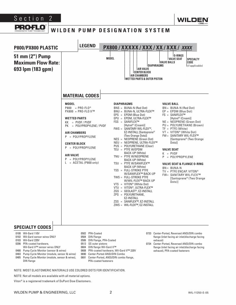
LEGEND PX800 / XXXXX / XXX / XX / XXX / XXXX
O-RINGSMODEL VALVE SEAT
VALVE BALLSDIAPHRAGMS
AIR VALVECENTER BLOCK
AIR CHAMBERSWETTED PARTS & OUTER PISTON
SPECIALTYCODE(if applicable)
MATERIAL CODES
MODELP800 = PRO-FLO®
PX800 = PRO-FLO X™
WETTED PARTSKK = PVDF / PVDFPK = POLYPROPYLENE / PVDF
AIR CHAMBERSP = POLYPROPYLENE
CENTER BLOCKP = POLYPROPYLENE
AIR VALVEP = POLYPROPYLENEL = ACETAL (P800 only)
DIAPHRAGMSBNS = BUNA-N (Red Dot)BNU = BUNA-N, ULTRA-FLEX™EPS = EPDM (Blue Dot)EPU = EPDM, ULTRA-FLEX™FSS = SANIFLEX™
[Hytrel® (Cream)]FWS = SANITARY WIL-FLEXTM,
EZ-INSTALL [Santoprene® (Two Orange Dots)]
NES = NEOPRENE (Green Dot)NEU = NEOPRENE, ULTRA-FLEX™PUS = POLYURETHANE (Clear)TEU = PTFE W/EPDM BACK-UP (White)TNU = PTFE W/NEOPRENE BACK-UP (White)TSU = PTFE W/SANIFLEX™
BACK-UP (White)TSS = FULL-STROKE PTFE W/SANIFLEX™ BACK-UPTWS = FULL-STROKE PTFE W/WIL-FLEX™ BACK-UPVTS = VITON® (White Dot)VTU = VITON®, ULTRA-FLEX™ZGS = GEOLAST®, EZ-INSTALLZPS = POLYURETHANE,
EZ-INSTALLZSS = SANIFLEX™, EZ-INSTALLZWS = WIL-FLEX™, EZ-INSTALL
VALVE BALLBN = BUNA-N (Red Dot)EP = EPDM (Blue Dot)FS = SANIFLEX™
[Hytrel® (Cream)]NE = NEOPRENE (Green Dot)PU = POLYURETHANE (Brown)TF = PTFE (White)VT = VITON® (White Dot)FW = SANITARY WIL-FLEX™
[Santoprene® (Two Orange Dots)]
VALVE SEATK = PVDFP = POLYPROPYLENE
VALVE SEAT & FLANGE O-RINGBN = BUNA-NTV = PTFE ENCAP. VITON®
FW = SANITARY WIL-FLEX™ [Santoprene® (Two Orange Dots)]
S e c t i o n 2
W I L D E N P U M P D E S I G N A T I O N S Y S T E M
REV 06/03/05 EFS
SPECIALTY CODES0100 Wil-Gard 110V0102 Wil-Gard sensor wires ONLY0103 Wil-Gard 220V0206 PFA-coated hardware, Wil-Gard II™ sensor wires ONLY 0480 Pump Cycle Monitor (sensor & wires)0483 Pump Cycle Monitor (module, sensor & wires)0485 Pump Cycle Monitor (module, sensor & wires),
DIN flange
0502 PFA-Coated0504 DIN Flange0506 DIN Flange, PFA-Coated0513 SS outer pistons0604 DIN flange Wil-Gard II™0608 PFA-coated hardware, Wil-Gard II™ 220V0690 Center-Ported ANSI/DIN Combo0691 Center-Ported, ANSI/DIN combo flange,
PFA-coated fasteners
0733 Center-Ported, Reversed ANSI/DIN combo flange (inlet facing air inlet/discharge facing exhaust)
0734 Center-Ported, Reversed ANSI/DIN combo flange (inlet facing air inlet/discharge facing exhaust), PFA-coated fasteners
NOTE: MOST ELASTOMERIC MATERIALS USE COLORED DOTS FOR IDENTIFICATION.
NOTE: Not all models are available with all material options.
Viton® is a registered trademark of DuPont Dow Elastomers.
WIL-11250-E-05 3 WILDEN PUMP & ENGINEERING, LLC
S e c t i o n 3
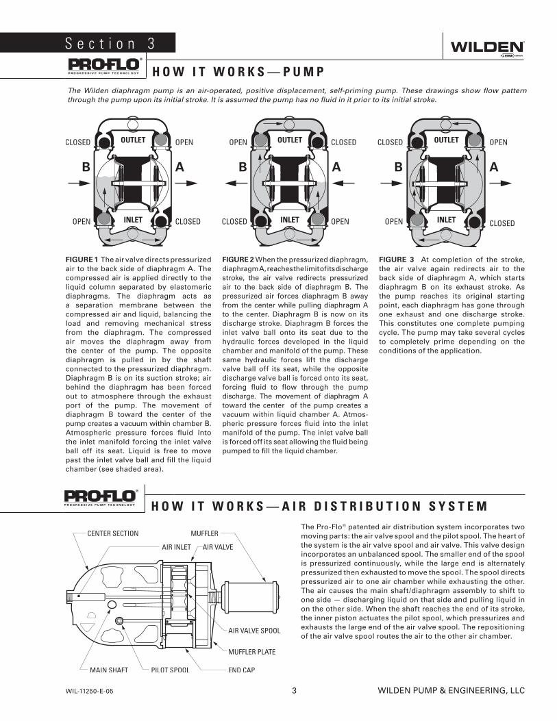
H O W I T W O R K S — P U M PThe Wilden diaphragm pump is an air-operated, positive displacement, self-priming pump. These drawings show flow pattern through the pump upon its initial stroke. It is assumed the pump has no fluid in it prior to its initial stroke.
FIGURE 1 The air valve directs pressurized air to the back side of diaphragm A. The compressed air is applied directly to the liquid column separated by elastomeric diaphragms. The diaphragm acts as a separation membrane between the compressed air and liquid, balancing the load and removing mechanical stress from the diaphragm. The compressed air moves the diaphragm away from the center of the pump. The opposite diaphragm is pulled in by the shaft connected to the pressurized diaphragm. Diaphragm B is on its suction stroke; air behind the diaphragm has been forced out to atmosphere through the exhaust port of the pump. The movement of diaphragm B toward the center of the pump creates a vacuum within chamber B. Atmospheric pressure forces fluid into the inlet manifold forcing the inlet valve ball off its seat. Liquid is free to move past the inlet valve ball and fill the liquid chamber (see shaded area).
FIGURE 2 When the pressurized diaphragm, diaphragm A, reaches the limit of its discharge stroke, the air valve redirects pressurized air to the back side of diaphragm B. The pressurized air forces diaphragm B away from the center while pulling diaphragm A to the center. Diaphragm B is now on its discharge stroke. Diaphragm B forces the inlet valve ball onto its seat due to the hydraulic forces developed in the liquid chamber and manifold of the pump. These same hydraulic forces lift the discharge valve ball off its seat, while the opposite discharge valve ball is forced onto its seat, forcing fluid to flow through the pump discharge. The movement of diaphragm A toward the center of the pump creates a vacuum within liquid chamber A. Atmos-pheric pressure forces fluid into the inlet manifold of the pump. The inlet valve ball is forced off its seat allowing the fluid being pumped to fill the liquid chamber.
FIGURE 3 At completion of the stroke, the air valve again redirects air to the back side of diaphragm A, which starts diaphragm B on its exhaust stroke. As the pump reaches its original starting point, each diaphragm has gone through one exhaust and one discharge stroke. This constitutes one complete pumping cycle. The pump may take several cycles to completely prime depending on the conditions of the application.
The Pro-Flo® patented air distribution system incorporates two moving parts: the air valve spool and the pilot spool. The heart of the system is the air valve spool and air valve. This valve design incorporates an unbalanced spool. The smaller end of the spool is pressurized continuously, while the large end is alternately pressurized then exhausted to move the spool. The spool directs pressurized air to one air chamber while exhausting the other. The air causes the main shaft/diaphragm assembly to shift to one side — discharging liquid on that side and pulling liquid in on the other side. When the shaft reaches the end of its stroke, the inner piston actuates the pilot spool, which pressurizes and exhausts the large end of the air valve spool. The repositioning of the air valve spool routes the air to the other air chamber.
H O W I T W O R K S — A I R D I S T R I B U T I O N S Y S T E M
P800 Plastic Side-Ported
S e c t i o n 4
D I M E N S I O N A L D R A W I N G S
P800 Plastic Center-PortedDIMENSIONS
ITEM METRIC (mm) STANDARD (inch)
A 584 23.0B 76 3.0C 396 15.6D 688 27.1E 765 30.1F 89 3.5G 91 3.6H 175 6.9J 353 13.9K 508 20.0L 399 15.7M 424 16.7N 361 14.2P 307 12.1R 208 8.2S 229 9.0T 254 10.0U 15 0.6
DIN / ANSI COMBOV 152 DIA. 6.0 DIA.W 122 DIA. 4.8 DIA.X 20 DIA. 0.8 DIA.
DIMENSIONSITEM METRIC (mm) STANDARD (inch)
A 605 23.8B 150 5.9C 91 3.6D 729 28.7E 406 16.0F 805 31.7G 353 13.9H 508 20.0J 406 16.0K 84 3.3L 122 4.8M 424 16.7N 361 14.2P 208 8.2R 234 9.2S 15 0.6
DIN FLANGET 125 DIA. 4.9 DIA.U 165 DIA. 6.5 DIA.V 18 DIA. 0.7 DIA.
ANSI FLANGET 122 DIA. 4.8 DIA.U 152 DIA. 6.0 DIA.V 20 DIA. 0.8 DIA.
WILDEN PUMP & ENGINEERING, LLC 4 WIL-11250-E-05
PX800 Plastic Center-Ported
PX800 Plastic Side-Ported DIMENSIONSITEM METRIC (mm) STANDARD (inch)
A 605 23.8B 150 5.9C 729 28.7D 91 3.6E 406 16.0F 805 31.7G 48 1.9H 178 7.0J 356 14.0K 452 17.8L 414 16.3M 424 16.7N 361 14.2P 208 8.2R 234 9.2S 15 0.6
DIN FLANGET 125 DIA. 4.9 DIA.U 165 DIA. 6.5 DIA.V 18 DIA. 0.7 DIA.
ANSI FLANGET 122 DIA. 4.8 DIA.U 154 DIA. 6.0 DIA.V 20 DIA. 0.8 DIA.
DIMENSIONSITEM METRIC (mm) STANDARD (inch)
A 584 23.0B 76 3.0C 396 15.6D 688 27.1E 765 30.1F 89 3.5G 48 1.9H 178 7.0J 356 14.0K 452 17.8L 404 15.9M 424 16.7N 361 14.2P 307 12.1R 208 8.2S 229 9.0T 254 10.0U 15 0.6
DIN / ANSI COMBOV 152 DIA. 6.0 DIA.W 122 DIA. 4.8 DIA.X 20 DIA. 0.8 DIA.
WIL-11250-E-05 5 WILDEN PUMP & ENGINEERING, LLC
D I M E N S I O N A L D R A W I N G
P800 PLASTICRUBBER-FITTED
Flow rates indicated on chart were determined by pumping water.
For optimum life and performance, pumps should be specified so that daily operation parameters will fall in the center of the pump's performance curve.
Height ..................................805 mm (31.7")Width .................................. 605 mm (23.8") Depth .................................. 353 mm (13.9") Ship Weight ......Polypropylene 32 kg (70 lbs) PVDF 45 kg (99 lbs) Air Inlet ....................................13 mm (1⁄2")Inlet ............................................ 51 mm (2")Outlet ......................................... 51 mm (2")Suction Lift ..................... 6.23 m Dry (20.4') 8.65 m Wet (28.4')Displacement/Stroke 2.75 L (0.73 gal)1
Max. Flow Rate ............ 624 lpm (165 gpm)Max. Size Solids .....................6.4 mm (1⁄4")1Displacement per stroke was calculated at 4.8 bar (70 psig) air inlet pressure against a 2.1 bar (30 psig) head pressure.
Example: To pump 246 lpm (65 gpm) against a discharge head pressure of 2.8 bar (40 psig) requires 4.1 bar (60 psig) and 85 Nm3/h (50 scfm) air consumption. (See dot on chart.)
Caution: Do not exceed 8.6 bar (125 psig) air supply pressure.
P800 PLASTICTPE-FITTED
Flow rates indicated on chart were determined by pumping water.
For optimum life and performance, pumps should be specified so that daily operation parameters will fall in the center of the pump's performance curve.
Height ..................................805 mm (31.7")Width .................................. 605 mm (23.8") Depth .................................. 353 mm (13.9") Ship Weight ......Polypropylene 32 kg (70 lbs) PVDF 45 kg (99 lbs) Air Inlet ....................................13 mm (1⁄2")Inlet ............................................ 51 mm (2")Outlet ......................................... 51 mm (2")Suction Lift ................... 5.54 m Dry (18.16') 8.66 m Wet (28.4') Displacement/Stroke ...... 2.78 L (0.74 gal)1
Max. Flow Rate ............ 615 lpm (162 gpm)Max. Size Solids .....................6.4 mm (1⁄4")1Displacement per stroke was calculated at 4.8 bar (70 psig) air inlet pressure against a 2.1 bar (30 psig) head pressure.
Example: To pump 322 lpm (85 gpm) against a discharge head pressure of 1.2 bar (17 psig) requires 2.8 bar (40 psig) and 85 Nm3/h (50 scfm) air consumption. (See dot on chart.)
Caution: Do not exceed 8.6 bar (125 psig) air supply pressure.
WILDEN PUMP & ENGINEERING, LLC 6 WIL-11250-E-05
S e c t i o n 5 A
P E R F O R M A N C E
P800 PLASTICREDUCED-STROKE PTFE-FITTED
P800 PLASTICFULL-STROKE PTFE-FITTED
Flow rates indicated on chart were determined by pumping water.
For optimum life and performance, pumps should be specified so that daily operation parameters will fall in the center of the pump's performance curve.
Flow rates indicated on chart were determined by pumping water.
For optimum life and performance, pumps should be specified so that daily operation parameters will fall in the center of the pump's performance curve.
Height ..................................805 mm (31.7")Width .................................. 605 mm (23.8") Depth .................................. 353 mm (13.9") Ship Weight ......Polypropylene 32 kg (70 lbs) PVDF 45 kg (99 lbs)Air Inlet ....................................13 mm (1⁄2")Inlet ............................................ 51 mm (2")Outlet ......................................... 51 mm (2")Suction Lift ................... 4.15 m Dry (13.62') 8.65 m Wet (28.4') Displacement/Stroke .... 1.73 L (0.457 gal)1
Max. Flow Rate ............ 504 lpm (133 gpm)Max. Size Solids .....................6.4 mm (1⁄4")1Displacement per stroke was calculated at 4.8 bar (70 psig) air inlet pressure against a 2 bar (30 psig) head pressure.
Example: To pump 220 lpm (58 gpm) against a discharge head pressure of 3.4 bar (50 psig) requires 5.5 bar (80 psig) and 128 Nm3/h (75 scfm) air consumption. (See dot on chart.)
Caution: Do not exceed 8.6 bar (125 psig) air supply pressure.
Height ................................. 804 mm (31.7”)Width ..................................604 mm (23.8”)Depth ..................................353 mm (13.9”)Ship Weight ......Polypropylene 32 kg (70 lbs) PVDF 45 kg (99 lbs) Air Inlet ...................................13 mm (1/2”)Inlet ............................................51 mm (2”) Outlet .........................................51 mm (2”)Suction Lift ........................ 5.9m Dry (19.5’) 9.0 m Wet (29.5’)Disp. Per Stroke ................. 2.5 L (0.67 gal)1
Max. Flow Rate ............ 615 lpm (162 gpm)Max. Size Solids ....................6.4 mm (1/4”)1Displacement per stroke was calculated at 4.8 bar (70 psig) air inlet pressure against a 2.1 bar (30 psig) head pressure.
Example: To pump 371 lpm (98 gpm) against a discharge head of 2.8 bar (40 psig) requires 5.5 bar (80 psig) and 147.9 Nm3/h (92 scfm) air consumption.
Caution: Do not exceed 8.6 bar (125 psig) air supply pressure.
60 [102]
100 [170] 80 [136]
120 [204]
20 40 60 80 100 120 140 160 [76] [151] [227] [303] [379] [454] [530] [606]
40 [68] 20 [34]
WIL-11250-E-05 7 WILDEN PUMP & ENGINEERING, LLC
P E R F O R M A N C E
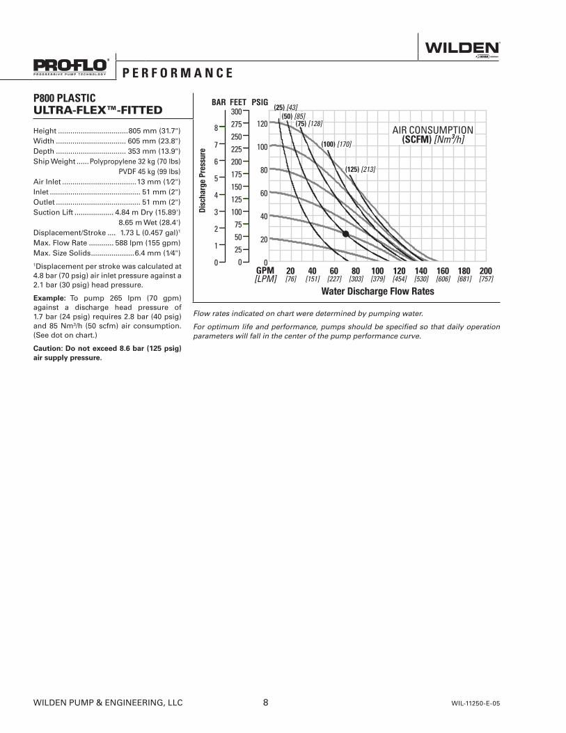
P800 PLASTICULTRA-FLEX™-FITTED
Flow rates indicated on chart were determined by pumping water.
For optimum life and performance, pumps should be specified so that daily operation parameters will fall in the center of the pump performance curve.
Height ..................................805 mm (31.7")Width .................................. 605 mm (23.8") Depth .................................. 353 mm (13.9") Ship Weight ......Polypropylene 32 kg (70 lbs) PVDF 45 kg (99 lbs) Air Inlet ....................................13 mm (1⁄2")Inlet ............................................ 51 mm (2")Outlet ......................................... 51 mm (2")Suction Lift ................... 4.84 m Dry (15.89') 8.65 m Wet (28.4') Displacement/Stroke .... 1.73 L (0.457 gal)1
Max. Flow Rate ............ 588 lpm (155 gpm)Max. Size Solids .....................6.4 mm (1⁄4")1Displacement per stroke was calculated at 4.8 bar (70 psig) air inlet pressure against a 2.1 bar (30 psig) head pressure.
Example: To pump 265 lpm (70 gpm) against a discharge head pressure of 1.7 bar (24 psig) requires 2.8 bar (40 psig) and 85 Nm3/h (50 scfm) air consumption. (See dot on chart.)
Caution: Do not exceed 8.6 bar (125 psig) air supply pressure.
WILDEN PUMP & ENGINEERING, LLC 8 WIL-11250-E-05
P E R F O R M A N C E

P800 PLASTICSUCTION-LIFT CAPABILITY
S e c t i o n 5 A
S U C T I O N - L I F T C U R V E
WIL-11250-E-05 9 WILDEN PUMP & ENGINEERING, LLC

N O T E S
PX800
P L A S T I C
P X 8 0 0 P E R F O R M A N C E
WIL-11250-E-05 11 WILDEN PUMP & ENGINEERING, LLC
WILDEN PUMP & ENGINEERING, LLC 12 PX800 Performance
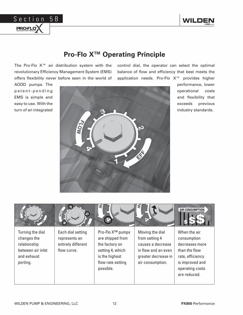
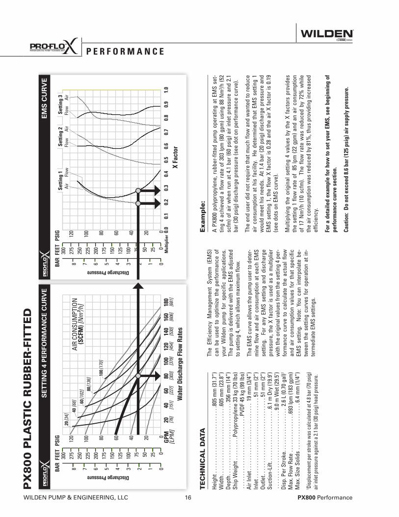
The Pro-Flo X™ air distribution system with the
revolutionary Efficiency Management System (EMS)
offers flexibility never before seen in the world of
AODD pumps. The
p a t e n t - p e n d i n g
EMS is simple and
easy to use. With the
turn of an integrated
control dial, the operator can select the optimal
balance of flow and efficiency that best meets the
application needs. Pro-Flo X™ provides higher
performance, lower
operational costs
and flexibility that
exceeds previous
industry standards.
Pro-Flo XTM Operating Principle
S e c t i o n 5 B
Turning the dial changes the relationship between air inlet and exhaust porting.
Each dial setting represents an entirely different flow curve.
Pro-Flo X™ pumps are shipped from the factory on setting 4, which is the highest flow rate setting possible.
Moving the dial from setting 4 causes a decrease in flow and an even greater decrease in air consumption.
When the air consumption decreases more than the flow rate, efficiency is improved and operating costs are reduced.
$$$
AIR CONSUMPTION

PX800 Performance 13 WILDEN PUMP & ENGINEERING, LLC
SETTING 4 PERFORMANCE CURVE EMS CURVE
H O W T O U S E T H I S E M S C U R V E
Example 1
8.2 GPMExample data point = Example data point =
Figure 1 Figure 20.580.48
flow multiplier
air multiplier
This is an example showing how to determine flow rate and air consumption for your Pro-Flo X™ pump using the Efficien-cy Management System (EMS) curve and the performance curve. For this example we will be using 4.1 bar (60 psig) inlet air pressure and 2.8 bar (40 psig) discharge pressure and EMS setting 2.
Step 1: Identifying performance at setting 4. Locate the curve that represents the flow rate of the pump with 4.1 bar (60 psig) air inlet pressure. Mark the point where this curve crosses the horizontal line representing 2.8 bar (40 psig) discharge pressure (Figure 1). After locating your performance point on the flow curve, draw a vertical line downward until reaching the bottom scale on the chart. Identify the flow rate (in this case, 8.2 gpm). Observe location of performance point relative to air consump-tion curves and approximate air consumption value (in this case, 9.8 scfm).
Step 2: Determining flow and air X Factors. Locate your discharge pressure [2.8 bar (40 psig)] on the vertical axis of the EMS curve (Figure 2). Follow along the 2.8 bar (40 psig) horizontal line until intersecting both flow and air curves for your desired EMS setting (in this case, set-ting 2). Mark the points where the EMS curves intersect the horizontal discharge pressure line. After locating your EMS points on the
EMS curve, draw vertical lines downward until reaching the bottom scale on the chart. This identifies the flow X Factor (in this case, 0.58) and air X Factor (in this case, 0.48).
Step 3: Calculating performance for specific EMS setting. Multiply the flow rate (8.2 gpm) obtained in Step 1 by the flow X Factor multi-plier (0.58) in Step 2 to determine the flow rate at EMS setting 2. Multiply the air consump-tion (9.8 scfm) obtained in Step 1 by the air X Factor multiplier (0.48) in Step 2 to deter-mine the air consumption at EMS setting 2 (Figure 3).
Figure 3
The flow rate and air consumption at Setting 2 are found to be 18.2 lpm (4.8 gpm) and 7.9 Nm3/h (4.7 scfm) respectively.
.584.8 gpm
(Flow X Factor setting 2)
(Flow rate for setting 2)
(air consumption for setting 4)(Air X Factor setting 2)
(air consumption for setting 2)
9.8 scfm
.484.7 scfm
8.2 gpm (flow rate for setting 4)
WILDEN PUMP & ENGINEERING, LLC 14 PX800 Performance
EMS CURVESETTING 4 PERFORMANCE CURVE
H O W T O U S E T H I S E M S C U R V E
This is an example showing how to determine the inlet air pressure and the EMS setting for your Pro-Flo X™ pump to optimize the pump for a specific application. For this exam-ple we will be using an application requirement of 18.9 lpm (5 gpm) flow rate against 2.8 bar (40 psig) discharge pressure. This example will illustrate how to calculate the air consump-tion that could be expected at this operational point.
Step 1: Establish inlet air pressure. Higher air pres-sures will typically allow the pump to run more efficiently, however, available plant air pressure can vary greatly. If an operating pressure of 6.9 bar (100 psig) is chosen when plant air frequently dips to 6.2 bar (90 psig) pump performance will vary. Choose an oper-ating pressure that is within your compressed air system's capabilities. For this example we will choose 4.1 bar (60 psig).
Step 2: Determine performance point at setting 4. For this example an inlet air pressure of 4.1 bar (60 psig) inlet air pressure has been chosen. Locate the curve that represents the perfor-mance of the pump with 4.1 bar (60 psig) inlet air pressure. Mark the point where this curve crosses the horizontal line representing 2.8 bar (40 psig) discharge pressure. After locat-ing this point on the flow curve, draw a verti-cal line downward until reaching the bottom scale on the chart and identify the flow rate.
In our example it is 38.6 lpm (10.2 gpm). This is the setting 4 flow rate. Observe the loca-tion of the performance point relative to air consumption curves and approximate air consumption value. In our example setting 4 air consumption is 24 Nm3/h (14 scfm). (See Figure 4.)
Step 3: Determine flow X Factor. Divide the required flow rate 18.9 lpm (5 gpm) by the setting 4 flow rate 38.6 lpm (10.2 gpm) to determine the flow X Factor for the application.
Step 4: Determine EMS setting from the flow X Factor. Plot the point representing the flow X Factor (0.49) and the application discharge pressure 2.8 bar (40 psig) on the EMS curve. This is done by following the horizontal 2.8 bar (40 psig) discharge pressure line until it crosses the vertical 0.49 X Factor line. Typical-ly, this point lies between two flow EMS set-ting curves (in this case, the point lies between the flow curves for EMS setting 1 and 2). Ob-serve the location of the point relative to the two curves it lies between and approximate the EMS setting (Figure 5). For more precise results you can mathematically interpolate be-tween the two curves to determine the opti-mal EMS setting.
5 gpm / 10.2 gpm = 0.49 (flow X Factor)
DETERMINE EMS SETTING
For this example the EMS setting is 1.8.
Figure 4
Example data point = 10.2 gpm flow multiplier
Figure 5
EMS FlowSettings 1 & 2
0.49
Example 2.1
PX800 Performance 15 WILDEN PUMP & ENGINEERING, LLC
EMS CURVESETTING 4 PERFORMANCE CURVE
H O W T O U S E T H I S E M S C U R V E
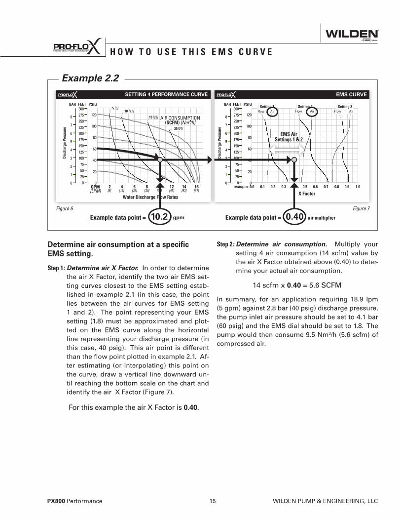
Example 2.2
Determine air consumption at a specific EMS setting.
Step 1: Determine air X Factor. In order to determine the air X Factor, identify the two air EMS set-ting curves closest to the EMS setting estab-lished in example 2.1 (in this case, the point lies between the air curves for EMS setting 1 and 2). The point representing your EMS setting (1.8) must be approximated and plot-ted on the EMS curve along the horizontal line representing your discharge pressure (in this case, 40 psig). This air point is different than the flow point plotted in example 2.1. Af-ter estimating (or interpolating) this point on the curve, draw a vertical line downward un-til reaching the bottom scale on the chart and identify the air X Factor (Figure 7).
Step 2: Determine air consumption. Multiply your setting 4 air consumption (14 scfm) value by the air X Factor obtained above (0.40) to deter-mine your actual air consumption.
In summary, for an application requiring 18.9 lpm (5 gpm) against 2.8 bar (40 psig) discharge pressure, the pump inlet air pressure should be set to 4.1 bar (60 psig) and the EMS dial should be set to 1.8. The pump would then consume 9.5 Nm3/h (5.6 scfm) of compressed air.
Figure 6
0.40 air multiplierExample data point = Figure 7
10.2 gpmExample data point =
For this example the air X Factor is 0.40.
14 scfm x 0.40 = 5.6 SCFM
EMS AirSettings 1 & 2
WILDEN PUMP & ENGINEERING, LLC 16 PX800 Performance
P E R F O R M A N C ES
ETT
ING
4 P
ER
FOR
MA
NC
E C
UR
VE
EM
S C
UR
VE
PX
80
0 P
LAS
TIC
RU
BB
ER
-FIT
TE
D
TE
CH
NIC
AL
DA
TA
Heig
ht .
....
....
....
....
....
....
.805
mm
(31.
7”)
Wid
th..
....
....
....
....
....
....
.605
mm
(23.
8”)
Dept
h...
....
....
....
....
....
....
.356
mm
(14”
)Sh
ip W
eigh
t ...
....
..Po
lypr
opyl
ene
33 k
g (7
0 lb
s) .
. . .
. . .
. . .
. . .
. . .
. . .
. . .
. . .
. . .P
VDF
45 k
g (9
9 lb
s)Ai
r Inl
et..
....
....
....
....
....
....
19 m
m (3
/4”)
Inle
t . .
. . .
. . .
. . .
. . .
. . .
. . .
. . .
. . .
. . .
. . 5
1 m
m (2
”)
Outle
t...
....
....
....
....
....
....
...5
1 m
m (2
”)Su
ctio
n-Li
ft...
....
....
....
....
..6.
1 m
Dry
(19.
9’)
...
....
....
....
....
....
....
...9
.0 m
Wet
(29.
5’)
Disp
. Per
Stro
ke..
....
....
....
...
2.6
L (0
.70
gal)1
Max
. Flo
w R
ate
....
....
....
...6
93 lp
m (1
83 g
pm)
Max
. Size
Sol
ids
....
....
....
....
..6.
4 m
m (1
/4”)
1 Disp
lace
men
t per
stro
ke w
as c
alcu
late
d at
4.8 b
ar (7
0 psig
) ai
r inl
et p
ress
ure
agai
nst a
2.1 b
ar (3
0 psig
) hea
d pr
essu
re.
The
Effic
ienc
y M
anag
emen
t Sy
stem
(EM
S)
can
be u
sed
to o
ptim
ize t
he p
erfo
rman
ce o
f yo
ur W
ilden
pum
p fo
r sp
ecifi
c ap
plic
atio
ns.
The
pum
p is
del
iver
ed w
ith th
e EM
S ad
just
ed
to s
ettin
g 4,
whi
ch a
llow
s m
axim
um fl
ow.
The
EMS
curv
e al
low
s th
e pu
mp
user
to d
eter
-m
ine
flow
and
air
cons
umpt
ion
at e
ach
EMS
setti
ng.
For
any
EMS
setti
ng a
nd d
isch
arge
pr
essu
re, t
he X
fact
or is
use
d as
a m
ultip
lier
with
the
orig
inal
val
ues
from
the
setti
ng 4
per
-fo
rman
ce c
urve
to
calc
ulat
e th
e ac
tual
flow
an
d ai
r co
nsum
ptio
n va
lues
for
tha
t sp
ecifi
c EM
S se
tting
. N
ote:
You
can
inte
rpol
ate
be-
twee
n th
e se
tting
cur
ves
for
oper
atio
n at
in-
term
edia
te E
MS
setti
ngs.
Exa
mp
le:
A PX
800
poly
prop
ylen
e, r
ubbe
r-fit
ted
pum
p op
erat
ing
at E
MS
set-
ting
4 ac
hiev
ed a
flow
rate
of 3
03 lp
m (8
0 gp
m) u
sing
88
Nm
3 /h (5
2 sc
fm) o
f air
whe
n ru
n at
4.1
bar
(60
psig
) air
inle
t pre
ssur
e an
d 2.
1 ba
r (30
psi
g) d
isch
arge
pre
ssur
e (s
ee d
ot o
n pe
rform
ance
cur
ve).
The
end
user
did
not
requ
ire th
at m
uch
flow
and
wan
ted
to re
duce
ai
r co
nsum
ptio
n at
his
faci
lity.
He
det
erm
ined
that
EM
S se
tting
1
wou
ld m
eet h
is n
eeds
. At
1.4
bar
(20
psig
) dis
char
ge p
ress
ure
and
EMS
setti
ng 1
, the
flow
X fa
ctor
is 0
.28
and
the
air
X fa
ctor
is 0
.19
(see
dot
s on
EM
S cu
rve)
.
Mul
tiply
ing
the
orig
inal
set
ting
4 va
lues
by
the
X fa
ctor
s pr
ovid
es
the
setti
ng 1
flow
rate
of
85 lp
m (2
2 gp
m) a
nd a
n ai
r con
sum
ptio
n of
17
Nm
3 /h (
10 s
cfm
). T
he fl
ow r
ate
was
red
uced
by
72%
whi
le
the
air c
onsu
mpt
ion
was
redu
ced
by 8
1%, t
hus
prov
idin
g in
crea
sed
effic
ienc
y.
For a
det
aile
d ex
ampl
e fo
r how
to s
et y
our E
MS,
see
beg
inni
ng o
f pe
rfor
man
ce c
urve
sec
tion.
Caut
ion:
Do
not e
xcee
d 8.
6 ba
r (12
5 ps
ig) a
ir s
uppl
y pr
essu
re.

PX800 Performance 17 WILDEN PUMP & ENGINEERING, LLC
P E R F O R M A N C E
SE
TTIN
G 4
PE
RFO
RM
AN
CE
CU
RV
EE
MS
CU
RV
E
0.
0 0.
1 0.
2 0.
3 0.
4 0.
5 0.
6 0.
7 0.
8 0.
9 1.
0
Flow
Se
tting
1
Mul
tiplie
r
X Fa
ctor
Air
Flow
Se
tting
2
Flow
Se
tting
3Ai
r Ai
r
PX
80
0 P
LAS
TIC
TP
E-F
ITT
ED
EX
AM
PLE
A PX
800
poly
prop
ylen
e, T
PE-fi
tted
pum
p op
erat
ing
at E
MS
setti
ng 4
, ac
hiev
ed a
flow
rate
of 5
22 lp
m (1
38 g
pm) u
sing
170
Nm
3 /h (1
00 s
cfm
) of
air
whe
n ru
n at
6.9
bar
(100
psi
g) a
ir in
let p
ress
ure
and
1.4
bar (
20
psig
) dis
char
ge p
ress
ure
(see
dot
on
perfo
rman
ce c
urve
).
The
end
user
did
not
requ
ire th
at m
uch
flow
and
wan
ted
to re
duce
ai
r co
nsum
ptio
n at
his
faci
lity.
He
det
erm
ined
that
EM
S se
tting
2
wou
ld m
eet h
is n
eeds
. At
1.4
bar
(20
psig
) dis
char
ge p
ress
ure
and
EMS
setti
ng 2
, the
flow
X fa
ctor
is 0
.68
and
the
air
X fa
ctor
is 0
.48
(see
dot
s on
EM
S cu
rve)
.
Mul
tiply
ing
the
orig
inal
set
ting
4 va
lues
by
the
tX fa
ctor
s pr
ovid
es
the
setti
ng 2
flow
rate
of 3
55 lp
m (9
4 gp
m) a
nd a
n ai
r con
sum
ptio
n of
82
Nm
3 /h (
48 s
cfm
). T
he fl
ow r
ate
was
red
uced
by
32%
whi
le
the
air c
onsu
mpt
ion
was
redu
ced
by 5
2%, t
hus
prov
idin
g in
crea
sed
effic
ienc
y.
For a
det
aile
d ex
ampl
e fo
r how
to s
et y
our E
MS,
see
beg
inni
ng o
f pe
rfor
man
ce c
urve
sec
tion.
Caut
ion:
Do
not e
xcee
d 8.
6 ba
r (12
5 ps
ig) a
ir s
uppl
y pr
essu
re.
The
Effic
ienc
y M
anag
emen
t Sy
stem
(EM
S)
can
be u
sed
to o
ptim
ize t
he p
erfo
rman
ce o
f yo
ur W
ilden
pum
p fo
r sp
ecifi
c ap
plic
atio
ns.
The
pum
p is
del
iver
ed w
ith th
e EM
S ad
just
ed
to s
ettin
g 4,
whi
ch a
llow
s m
axim
um fl
ow.
The
EMS
curv
e al
low
s th
e pu
mp
user
to d
eter
-m
ine
flow
and
air
cons
umpt
ion
at e
ach
EMS
setti
ng.
For
any
EMS
setti
ng a
nd d
isch
arge
pr
essu
re, t
he X
fact
or is
use
d as
a m
ultip
lier
with
the
orig
inal
val
ues
from
the
setti
ng 4
per
-fo
rman
ce c
urve
to
calc
ulat
e th
e ac
tual
flow
an
d ai
r co
nsum
ptio
n va
lues
for
tha
t sp
ecifi
c EM
S se
tting
. N
ote:
You
can
inte
rpol
ate
be-
twee
n th
e se
tting
cur
ves
for
oper
atio
n at
in-
term
edia
te E
MS
setti
ngs.
TE
CH
NIC
AL
DA
TA
Heig
ht .
....
....
....
....
....
....
.805
mm
(31.
7”)
Wid
th..
....
....
....
....
....
....
.605
mm
(23.
8”)
Dept
h...
....
....
....
....
....
....
.356
mm
(14”
)Sh
ip W
eigh
t ...
....
..Po
lypr
opyl
ene
33 k
g (7
0 lb
s)
PVDF
45
kg (9
9 lb
s)Ai
r Inl
et..
....
....
....
....
....
....
19 m
m (3
/4”)
Inle
t . .
. . .
. . .
. . .
. . .
. . .
. . .
. . .
. . .
. . .
. . 5
1 m
m (2
”)
Outle
t...
....
....
....
....
....
....
...5
1 m
m (2
”)Su
ctio
n-Li
ft...
....
....
....
....
..5.
4 m
Dry
(17.
6’)
9.
0 m
Wet
(29.
5’)
Disp
. Per
Stro
ke..
....
....
....
...
2.6
L (0
.70
gal)1
Max
. Flo
w R
ate
....
....
....
...6
89 lp
m (1
82 g
pm)
Max
. Size
Sol
ids
....
....
....
....
..6.
4 m
m (1
/4”)
1 Disp
lace
men
t per
stro
ke w
as c
alcu
late
d at
4.8 b
ar (7
0 psig
) ai
r inl
et p
ress
ure
agai
nst a
2.1 b
ar (3
0 psig
) hea
d pr
essu
re.
WILDEN PUMP & ENGINEERING, LLC 18 PX800 Performance
SE
TTIN
G 4
PE
RFO
RM
AN
CE
CU
RV
EE
MS
CU
RV
EP E R F O R M A N C E
PX
80
0 P
LAS
TIC
RE
DU
CE
D-S
TR
OK
E P
TFE
-FIT
TE
D
TE
CH
NIC
AL
DA
TA
Heig
ht .
....
....
....
....
....
....
.805
mm
(31.
7”)
Wid
th..
....
....
....
....
....
....
.605
mm
(23.
8”)
Dept
h...
....
....
....
....
....
....
.356
mm
(14”
)Sh
ip W
eigh
t ...
....
..Po
lypr
opyl
ene
33 k
g (7
0 lb
s)
PVDF
45
kg (9
9 lb
s)Ai
r Inl
et..
....
....
....
....
....
....
19 m
m (3
/4”)
Inle
t . .
. . .
. . .
. . .
. . .
. . .
. . .
. . .
. . .
. . .
. . 5
1 m
m (2
”)
Outle
t...
....
....
....
....
....
....
...5
1 m
m (2
”)Su
ctio
n-Li
ft...
....
....
....
....
..4.
5 m
Dry
(14.
8’)
7.
2 m
Wet
(23.
8’)
Disp
. Per
Stro
ke..
....
....
....
...
1.7
L (0
.46
gal)1
Max
. Flo
w R
ate
....
....
....
...5
79 lp
m (1
53 g
pm)
Max
. Size
Sol
ids
....
....
....
....
..6.
4 m
m (1
/4”)
1 Disp
lace
men
t per
stro
ke w
as c
alcu
late
d at
4.8 b
ar (7
0 psig
) ai
r inl
et p
ress
ure
agai
nst a
2.1 b
ar (3
0 psig
) hea
d pr
essu
re.
The
Effic
ienc
y M
anag
emen
t Sy
stem
(EM
S)
can
be u
sed
to o
ptim
ize t
he p
erfo
rman
ce o
f yo
ur W
ilden
pum
p fo
r sp
ecifi
c ap
plic
atio
ns.
The
pum
p is
del
iver
ed w
ith th
e EM
S ad
just
ed
to s
ettin
g 4,
whi
ch a
llow
s m
axim
um fl
ow.
The
EMS
curv
e al
low
s th
e pu
mp
user
to d
eter
-m
ine
flow
and
air
cons
umpt
ion
at e
ach
EMS
setti
ng.
For
any
EMS
setti
ng a
nd d
isch
arge
pr
essu
re, t
he X
fact
or is
use
d as
a m
ultip
lier
with
the
orig
inal
val
ues
from
the
setti
ng 4
per
-fo
rman
ce c
urve
to
calc
ulat
e th
e ac
tual
flow
an
d ai
r co
nsum
ptio
n va
lues
for
tha
t sp
ecifi
c EM
S se
tting
. N
ote:
You
can
inte
rpol
ate
be-
twee
n th
e se
tting
cur
ves
for
oper
atio
n at
in-
term
edia
te E
MS
setti
ngs.
EX
AM
PLE
A PX
800 p
olyp
ropy
lene
, red
uced
-stro
ke P
TFE-
fitte
d pu
mp
oper
atin
g at
EM
S se
tting
4, a
chie
ved
a flo
w ra
te o
f 439
lpm
(116
gpm
) usin
g 14
6 N
m3 /h
(86 s
cfm
) of a
ir w
hen
run
at 5.
5 bar
(80 p
sig) a
ir in
let p
ress
ure
and
0.7 b
ar (1
0 psig
) disc
harg
e pr
essu
re (s
ee d
ot o
n pe
rform
ance
cur
ve) .
The
end
user
did
not
requ
ire th
at m
uch
flow
and
wan
ted
to re
duce
ai
r con
sum
ptio
n at
his
faci
lity.
He
dete
rmin
ed th
at E
MS
setti
ng 2
w
ould
mee
t his
nee
ds.
At 0
.7 b
ar (1
0 ps
ig) d
isch
arge
pre
ssur
e an
d EM
S se
tting
2, t
he fl
ow X
fact
or is
0.6
7 an
d th
e ai
r X fa
ctor
is 0
.46
(see
dot
s on
EM
S cu
rve)
.
Mul
tiply
ing
the
orig
inal
set
ting
4 va
lues
by
the
X fa
ctor
s pr
ovid
es
the
setti
ng 2
flow
rate
of 2
94 lp
m (7
8 gp
m) a
nd a
n ai
r con
sum
ptio
n of
67
Nm
3 /h (4
0 sc
fm).
The
flow
rate
was
redu
ced
by 3
3% w
hile
the
air c
onsu
mpt
ion
was
redu
ced
by 5
4%, t
hus
prov
idin
g in
crea
sed
effic
ienc
y.
For a
det
aile
d ex
ampl
e fo
r how
to s
et y
our E
MS,
see
beg
inni
ng o
f pe
rfor
man
ce c
urve
sec
tion.
Caut
ion:
Do
not e
xcee
d 8.
6 ba
r (12
5 ps
ig) a
ir s
uppl
y pr
essu
re.
PX800 Performance 19 WILDEN PUMP & ENGINEERING, LLC
SE
TTIN
G 4
PE
RFO
RM
AN
CE
CU
RV
EE
MS
CU
RV
E
P E R F O R M A N C EP
X8
00
PLA
ST
IC F
ULL
-ST
RO
KE
PT
FE-F
ITT
ED
TE
CH
NIC
AL
DA
TA
Heig
ht .
....
....
....
....
....
....
.805
mm
(31.
7”)
Wid
th..
....
....
....
....
....
....
.605
mm
(23.
8”)
Dept
h...
....
....
....
....
....
....
.356
mm
(14”
)Sh
ip W
eigh
t ...
....
..Po
lypr
opyl
ene
33 k
g (7
0 lb
s)
PVDF
45
kg (9
9 lb
s)Ai
r Inl
et..
....
....
....
....
....
....
19 m
m (3
/4”)
Inle
t . .
. . .
. . .
. . .
. . .
. . .
. . .
. . .
. . .
. . .
. . 5
1 m
m (2
”)
Outle
t...
....
....
....
....
....
....
...5
1 m
m (2
”)Su
ctio
n-Li
ft...
....
....
....
....
.. 5
.9m
Dry
(19.
5’)
9.
0 m
Wet
(29.
5’)
Disp
. Per
Stro
ke..
....
....
....
...
2.5
L (0
.67
gal)1
Max
. Flo
w R
ate
....
....
....
.664
lpm
(175
.4 g
pm)
Max
. Size
Sol
ids
....
....
....
....
..6.
4 m
m (1
/4”)
1 Disp
lace
men
t per
stro
ke w
as c
alcu
late
d at
4.8 b
ar (7
0 psig
) ai
r inl
et p
ress
ure
agai
nst a
2.1 b
ar (3
0 psig
) hea
d pr
essu
re.
The
Effic
ienc
y M
anag
emen
t Sy
stem
(EM
S)
can
be u
sed
to o
ptim
ize t
he p
erfo
rman
ce o
f yo
ur W
ilden
pum
p fo
r sp
ecifi
c ap
plic
atio
ns.
The
pum
p is
del
iver
ed w
ith th
e EM
S ad
just
ed
to s
ettin
g 4,
whi
ch a
llow
s m
axim
um fl
ow.
The
EMS
curv
e al
low
s th
e pu
mp
user
to d
eter
-m
ine
flow
and
air
cons
umpt
ion
at e
ach
EMS
setti
ng.
For
any
EMS
setti
ng a
nd d
isch
arge
pr
essu
re, t
he X
fact
or is
use
d as
a m
ultip
lier
with
the
orig
inal
val
ues
from
the
setti
ng 4
per
-fo
rman
ce c
urve
to
calc
ulat
e th
e ac
tual
flow
an
d ai
r co
nsum
ptio
n va
lues
for
tha
t sp
ecifi
c EM
S se
tting
. N
ote:
You
can
inte
rpol
ate
be-
twee
n th
e se
tting
cur
ves
for
oper
atio
n at
in-
term
edia
te E
MS
setti
ngs.
EX
AM
PLE
A PX
800
plas
tic, f
ull-s
troke
PTF
E-fit
ted
pum
p op
erat
ing
at E
MS
set-
ting
4, a
chie
ved
a flo
w ra
te o
f 416
lpm
(110
gpm
) usi
ng 1
29 N
m3 /h
(76
scfm
) of a
ir w
hen
run
at 5
.5 b
ar (8
0 ps
ig) a
ir in
let p
ress
ure
and
2.1
bar (
30 p
sig)
dis
char
ge p
ress
ure
(see
dot
on
perfo
rman
ce c
urve
).
The
end
user
did
not
requ
ire th
at m
uch
flow
and
wan
ted
to re
duce
ai
r con
sum
ptio
n at
his
faci
lity.
He
dete
rmin
ed th
at E
MS
setti
ng 3
w
ould
mee
t his
nee
ds.
At 2
.1 b
ar (3
0 ps
ig) d
isch
arge
pre
ssur
e an
d EM
S se
tting
3, t
he fl
ow X
fact
or is
0.7
4 an
d th
e ai
r X fa
ctor
is 0
.66
(see
dot
s on
EM
S cu
rve)
.
Mul
tiply
ing
the
orig
inal
set
ting
4 va
lues
by
the
X fa
ctor
s pr
ovid
es
the
setti
ng 3
flow
rate
of 3
08 lp
m (8
1 gp
m) a
nd a
n ai
r con
sum
ptio
n of
85
Nm
3 /h (5
0 sc
fm).
The
flow
rate
was
redu
ced
by 2
6% w
hile
the
air c
onsu
mpt
ion
was
redu
ced
by 3
4%, t
hus
prov
idin
g in
crea
sed
effic
ienc
y.
For a
det
aile
d ex
ampl
e fo
r how
to s
et y
our E
MS,
see
beg
inni
ng o
f pe
rfor
man
ce c
urve
sec
tion.
Caut
ion:
Do
not e
xcee
d 8.
6 ba
r (12
5 ps
ig) a
ir s
uppl
y pr
essu
re.
WILDEN PUMP & ENGINEERING, LLC 20 PX800 Performance
SE
TTIN
G 4
PE
RFO
RM
AN
CE
CU
RV
EE
MS
CU
RV
EP E R F O R M A N C E
PX
80
0 P
LAS
TIC
ULT
RA
-FLE
XT
M-F
ITT
ED
EX
AM
PLE
A PX
800
poly
prop
ylen
e, U
ltra-
Flex
TM-fi
tted
pum
p op
erat
ing
at E
MS
setti
ng 4
, ach
ieve
d a
flow
rate
of 2
20 lp
m (5
8 gp
m) u
sing
131
Nm
3 /h
(77
scfm
) of a
ir w
hen
run
at 6
.9 b
ar (1
00 p
sig)
air
inle
t pre
ssur
e an
d 4.
1 bar
(60 p
sig)
dis
char
ge p
ress
ure
(see
dot
on
perfo
rman
ce c
urve
).
The
end
user
did
not
requ
ire th
at m
uch
flow
and
wan
ted
to re
duce
ai
r co
nsum
ptio
n at
his
faci
lity.
He
det
erm
ined
that
EM
S se
tting
3
wou
ld m
eet h
is n
eeds
. At
4.1
bar
(60
psig
) dis
char
ge p
ress
ure
and
EMS
setti
ng 3
, the
flow
X fa
ctor
is 0
.89
and
the
air
X fa
ctor
is 0
.81
(see
dot
s on
EM
S cu
rve)
.
Mul
tiply
ing
the
orig
inal
set
ting
4 va
lues
by
the
X fa
ctor
s pr
ovid
es
the
setti
ng 3
flow
rate
of 1
95 lp
m (5
2 gp
m) a
nd a
n ai
r con
sum
ptio
n of
106
Nm
3 /h (6
2 sc
fm).
The
flow
rat
e w
as r
educ
ed b
y 11
% w
hile
th
e ai
r con
sum
ptio
n w
as re
duce
d by
19%
, thu
s pr
ovid
ing
incr
ease
d ef
ficie
ncy.
For a
det
aile
d ex
ampl
e fo
r how
to s
et y
our E
MS,
see
beg
inni
ng o
f pe
rfor
man
ce c
urve
sec
tion.
Caut
ion:
Do
not e
xcee
d 8.
6 ba
r (12
5 ps
ig) a
ir s
uppl
y pr
essu
re.
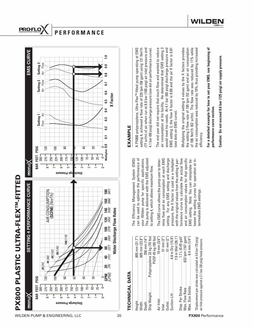
The
Effic
ienc
y M
anag
emen
t Sy
stem
(EM
S)
can
be u
sed
to o
ptim
ize t
he p
erfo
rman
ce o
f yo
ur W
ilden
pum
p fo
r sp
ecifi
c ap
plic
atio
ns.
The
pum
p is
del
iver
ed w
ith th
e EM
S ad
just
ed
to s
ettin
g 4,
whi
ch a
llow
s m
axim
um fl
ow.
The
EMS
curv
e al
low
s th
e pu
mp
user
to d
eter
-m
ine
flow
and
air
cons
umpt
ion
at e
ach
EMS
setti
ng.
For
any
EMS
setti
ng a
nd d
isch
arge
pr
essu
re, t
he X
fact
or is
use
d as
a m
ultip
lier
with
the
orig
inal
val
ues
from
the
setti
ng 4
per
-fo
rman
ce c
urve
to
calc
ulat
e th
e ac
tual
flow
an
d ai
r co
nsum
ptio
n va
lues
for
tha
t sp
ecifi
c EM
S se
tting
. N
ote:
You
can
inte
rpol
ate
be-
twee
n th
e se
tting
cur
ves
for
oper
atio
n at
in-
term
edia
te E
MS
setti
ngs.
TE
CH
NIC
AL
DA
TA
Heig
ht .
....
....
....
....
....
....
.805
mm
(31.
7”)
Wid
th..
....
....
....
....
....
....
.605
mm
(23.
8”)
Dept
h...
....
....
....
....
....
....
.356
mm
(14”
)Sh
ip W
eigh
t ...
....
..Po
lypr
opyl
ene
33 k
g (7
0 lb
s)
PVDF
45
kg (9
9 lb
s)Ai
r Inl
et..
....
....
....
....
....
....
19 m
m (3
/4”)
Inle
t . .
. . .
. . .
. . .
. . .
. . .
. . .
. . .
. . .
. . .
. . 5
1 m
m (2
”)Ou
tlet.
....
....
....
....
....
....
....
.51
mm
(2”)
Suct
ion-
Lift.
....
....
....
....
....
4.8
m D
ry (1
5.9’
)
7.9
m W
et (2
6.1’
)Di
sp. P
er S
troke
....
....
....
....
.1.
7 L
(0.4
5 ga
l)1
Max
. Flo
w R
ate
....
....
....
...6
32 lp
m (1
67 g
pm)
Max
. Size
Sol
ids
....
....
....
....
..6.
4 m
m (1
/4”)
1 Disp
lace
men
t per
stro
ke w
as c
alcu
late
d at
4.8 b
ar (7
0 psig
) ai
r inl
et p
ress
ure
agai
nst a
2.1 b
ar (3
0 psig
) hea
d pr
essu
re.
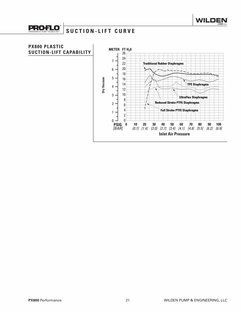
PX800 PLASTICSUCTION-LIFT CAPABILITY
TPE Diaphragms
Traditional Rubber Diaphragms
Full Stroke PTFE Diaphragms
Reduced Stroke PTFE Diaphragms
UltraFlex Diaphragms
S e c t i o n 5 C
S U C T I O N - L I F T C U R V E
PX800 Performance 21 WILDEN PUMP & ENGINEERING, LLC

N O T E S
WIL-11250-E-05 23 WILDEN PUMP & ENGINEERING, LLC
REV 05/09/05 DLC
Wilden pumps are designed to meet the performance requirements of even the most demanding pumping applications. They have been designed and manufactured to the highest standards and are available in a variety of liquid path materials to meet your chemical resistance needs. Refer to the performance section of this manual for an in-depth analysis of the performance characteristics of your pump. Wilden offers the widest variety of elastomer options in the industry to satisfy temperature, chemical compatibility, abrasion resistance and flex concerns.
The suction pipe size should be at least the equivalent or larger than the diameter size of the suction inlet on your Wilden pump. The suction hose must be non-collapsible, reinforced type as these pumps are capable of pulling a high vacuum. Discharge piping should also be the equivalent or larger than the diameter of the pump discharge which will help reduce friction losses. It is critical that all fittings and connections are airtight or a reduction or loss of pump suction capability will result.
INSTALLATION: Months of careful planning, study and selection efforts can result in unsatisfactory pump performance if installation details are left to chance.
Premature failure and long-term dissatisfaction can be avoided if reasonable care is exercised throughout the installation process.
LOCATION: Noise, safety and other logistical factors usually dictate where equipment will be situated on the production floor. Multiple installations with conflicting requirements can result in congestion of utility areas, leaving few choices for additional pumps.
Within the framework of these and other existing conditions, every pump should be located in such a way that six key factors are balanced against each other to maximum advantage.
ACCESS: First of all, the location should be accessible. If it’s easy to reach the pump, maintenance personnel will have an easier time carrying out routine inspections and adjustments. Should major repairs become necessary, ease of access can play a key role in speeding the repair process and reducing total downtime.
AIR SUPPLY: Every pump location should have an air line large enough to supply the volume of air necessary to achieve the desired pumping rate. Use air pressure up to a maximum of 8.6 bar (125 psig) depending on pumping requirements.
For best results, the pumps should use a 5µ (micron) air filter, needle valve and regulator. The use of an air filter before the pump will ensure that the majority of any pipeline contaminants will be eliminated.
SOLENOID OPERATION: When operation is controlled by a solenoid valve in the air line, three-way valves should be used. This valve allows trapped air between the valve and the pump to bleed off which improves pump performance. Pumping volume can be estimated by counting the number of strokes per minute and then multiplying the figure by the displacement per stroke.
MUFFLER: Sound levels are reduced below OSHA specifications using the standard Wilden muffler. Other mufflers can be used to further reduce sound levels, but they usually reduce pump performance.
ELEVATION: Selecting a site that is well within the pump’s dynamic lift capability will assure that loss-of-prime issues will be eliminated. In addition, pump efficiency can be adversely affected if proper attention is not given to site location.
PIPING: Final determination of the pump site should not be made until the piping challenges of each possible location have been evaluated. The impact of current and future installations should be considered ahead of time to make sure that inadvertent restrictions are not created for any remaining sites.
The best choice possible will be a site involving the shortest and straightest hook-up of suction and discharge piping. Unnecessary elbows, bends and fittings should be avoided. Pipe sizes should be selected to keep friction losses within practical limits. All piping should be supported independently of the pump. In addition, the piping should be aligned to avoid placing stress on the pump fittings.
Flexible hose can be installed to aid in absorbing the forces created by the natural reciprocating action of the pump. If the pump is to be bolted down to a solid location, a mounting pad placed between the pump and the foundation will assist in minimizing pump vibration. Flexible connections between the pump and rigid piping will also assist in minimizing pump vibration. If quick-closing valves are installed at any point in the discharge system, or if pulsation within a system becomes a problem, a surge suppressor (SD Equalizer®) should be installed to protect the pump, piping and gauges from surges and water hammer.
If the pump is to be used in a self-priming application, make sure that all connections are airtight and that the suction lift is within the model’s ability. Note: Materials of construction and elastomer material have an effect on suction-lift parameters. Please refer to the performance section for specifics.
When pumps are installed in applications involving flooded suction or suction head pressures, a gate valve should be installed in the suction line to permit closing of the line for pump service.
Pumps in service with a positive suction head are most efficient when inlet pressure is limited to 0.5–0.7 bar (7–10 psig). Premature diaphragm failure may occur if positive suction is 0.7 bar (10 psig) and higher.
SUBMERSIBLE APPLICATIONS: Pro-Flo X™ pumps can be used for submersible applications, when using the Pro-Flo X™ single point exhaust option.
NOTE: Pro-Flo® and Accu-Flo™ pumps are not submersible.
ALL WILDEN PUMPS ARE CAPABLE OF PASSING SOLIDS. A STRAINER SHOULD BE USED ON THE PUMP INTAKE TO ENSURE THAT THE PUMP'S RATED SOLIDS CAPACITY IS NOT EXCEEDED.
CAUTION: DO NOT EXCEED 8.6 BAR (125 PSIG) AIR SUPPLY PRESSURE.
S e c t i o n 6
S U G G E S T E D I N S T A L L A T I O N
WILDEN PUMP & ENGINEERING, LLC 24 WIL-11250-E-05
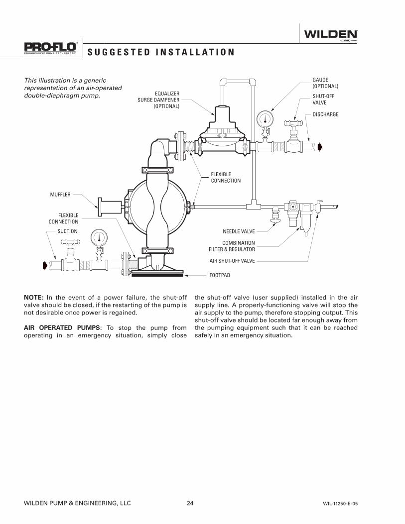
NOTE: In the event of a power failure, the shut-off valve should be closed, if the restarting of the pump is not desirable once power is regained.
AIR OPERATED PUMPS: To stop the pump from operating in an emergency situation, simply close
the shut-off valve (user supplied) installed in the air supply line. A properly-functioning valve will stop the air supply to the pump, therefore stopping output. This shut-off valve should be located far enough away from the pumping equipment such that it can be reached safely in an emergency situation.
This illustration is a generic representation of an air-operated double-diaphragm pump.
S U G G E S T E D I N S T A L L A T I O N
WIL-11250-E-05 25 WILDEN PUMP & ENGINEERING, LLC
S U G G E S T E D O P E R A T I O N & M A I N T E N A N C E
OPERATION: The P800 and PX800 are pre-lubricated and do not require in-line lubrication. Additional lubrication will not damage the pump, however if the pump is heavily lubricated by an external source, the pump’s internal lubrication may be washed away. If the pump is then moved to a non-lubricated location, it may need to be disassembled and re-lubricated as described in the ASSEMBLY/DISASSEMBLY INSTRUCTIONS.
Pump discharge rate can be controlled by limiting the volume and/or pressure of the air supply to the pump. An air regulator is used to regulate air pressure. A needle valve is used to regulate volume. Pump discharge rate can also be controlled by throttling the pump discharge by partially closing a valve in the discharge line of the pump. This action increases friction loss which reduces flow rate. (See Section 5.) This is useful when the need exists to control the pump from a remote location. When the pump discharge pressure equals or exceeds the air supply pressure, the pump will stop; no bypass or pressure relief valve is needed, and pump damage will not occur. The pump has reached a “deadhead” situation and can
be restarted by reducing the fluid discharge pressure or increasing the air inlet pressure. The Wilden P800 and PX800 pumps run solely on compressed air and do not generate heat, therefore your process fluid temperature will not be affected.
MAINTENANCE AND INSPECTIONS: Since each application is unique, maintenance schedules may be different for every pump. Frequency of use, line pressure, viscosity and abrasiveness of process fluid all affect the parts life of a Wilden pump. Periodic inspections have been found to offer the best means for preventing unscheduled pump downtime. Personnel familiar with the pump’s construction and service should be informed of any abnormalities that are detected during operation.
RECORDS: When service is required, a record should be made of all necessary repairs and replacements. Over a period of time, such records can become a valuable tool for predicting and preventing future maintenance problems and unscheduled downtime. In addition, accurate records make it possible to identify pumps that are poorly suited to their applications.
T R O U B L E S H O O T I N G
Pump will not run or runs slowly.
1. Ensure that the air inlet pressure is at least 0.4 bar (5 psig) above startup pressure and that the differential pressure (the difference between air inlet and liquid discharge pressures) is not less than 0.7 bar (10 psig).
2. Check air inlet filter for debris (see SUGGESTED INSTALLATION).
3. Check for extreme air leakage (blow by) which would indicate worn seals/bores in the air valve, pilot spool and main shaft.
4. Disassemble pump and check for obstructions in the air passageways or objects which would obstruct the movement of internal parts.
5. Check for sticking ball check valves. If material being pumped is not compatible with pump elastomers, swelling may occur. Replace ball check valves and seals with proper elastomers. Also, as the check valve balls wear out, they become smaller and can become stuck in the seats. In this case, replace balls and seats.
6. Check for broken inner piston which will cause the air valve spool to be unable to shift.
7. Remove plug from pilot spool exhaust.
Pump runs but little or no product flows.
1. Check for pump cavitation; slow pump speed down to allow thick material to flow into liquid chambers.
2. Verify that vacuum required to lift liquid is not greater than the vapor pressure of the material being pumped (cavitation).
3. Check for sticking ball check valves. If material being pumped is not compatible with pump elastomers, swelling may occur. Replace ball check valves and seats with proper elastomers. Also, as the check valve balls wear out, they become smaller and can become stuck in the seats. In this case, replace balls and seats.
Pump air valve freezes.
1. Check for excessive moisture in compressed air. Either install a dryer or hot air generator for compressed air. Alternatively, a coalescing filter may be used to remove the water from the compressed air in some applications.
Air bubbles in pump discharge.
1. Check for ruptured diaphragm.2. Check tightness of outer pistons (refer to Section 7).3. Check tightness of fasteners and integrity of
O-rings and seals, especially at intake manifold.4. Ensure pipe connections are airtight.
Product comes out air exhaust.
1. Check for diaphragm rupture.2. Check tightness of outer pistons to shaft.
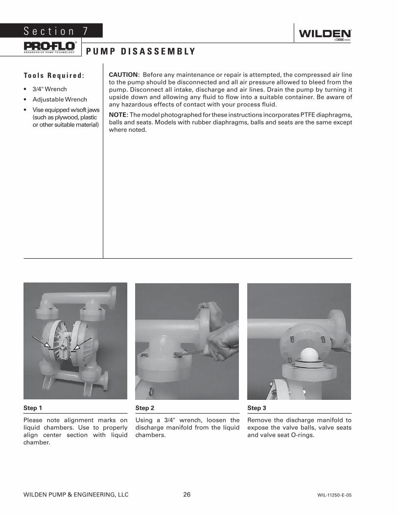
Step 1
Please note alignment marks on liquid chambers. Use to properly align center section with liquid chamber.
Step 2
Using a 3/4" wrench, loosen the discharge manifold from the liquid chambers.
Step 3
Remove the discharge manifold to expose the valve balls, valve seats and valve seat O-rings.
S e c t i o n 7
P U M P D I S A S S E M B L Y
To o l s R e q u i r e d :
• 3/4" Wrench
• Adjustable Wrench
• Vise equipped w/soft jaws (such as plywood, plastic or other suitable material)
CAUTION: Before any maintenance or repair is attempted, the compressed air line to the pump should be disconnected and all air pressure allowed to bleed from the pump. Disconnect all intake, discharge and air lines. Drain the pump by turning it upside down and allowing any fluid to flow into a suitable container. Be aware of any hazardous effects of contact with your process fluid.
NOTE: The model photographed for these instructions incorporates PTFE diaphragms, balls and seats. Models with rubber diaphragms, balls and seats are the same except where noted.
WILDEN PUMP & ENGINEERING, LLC 26 WIL-11250-E-05
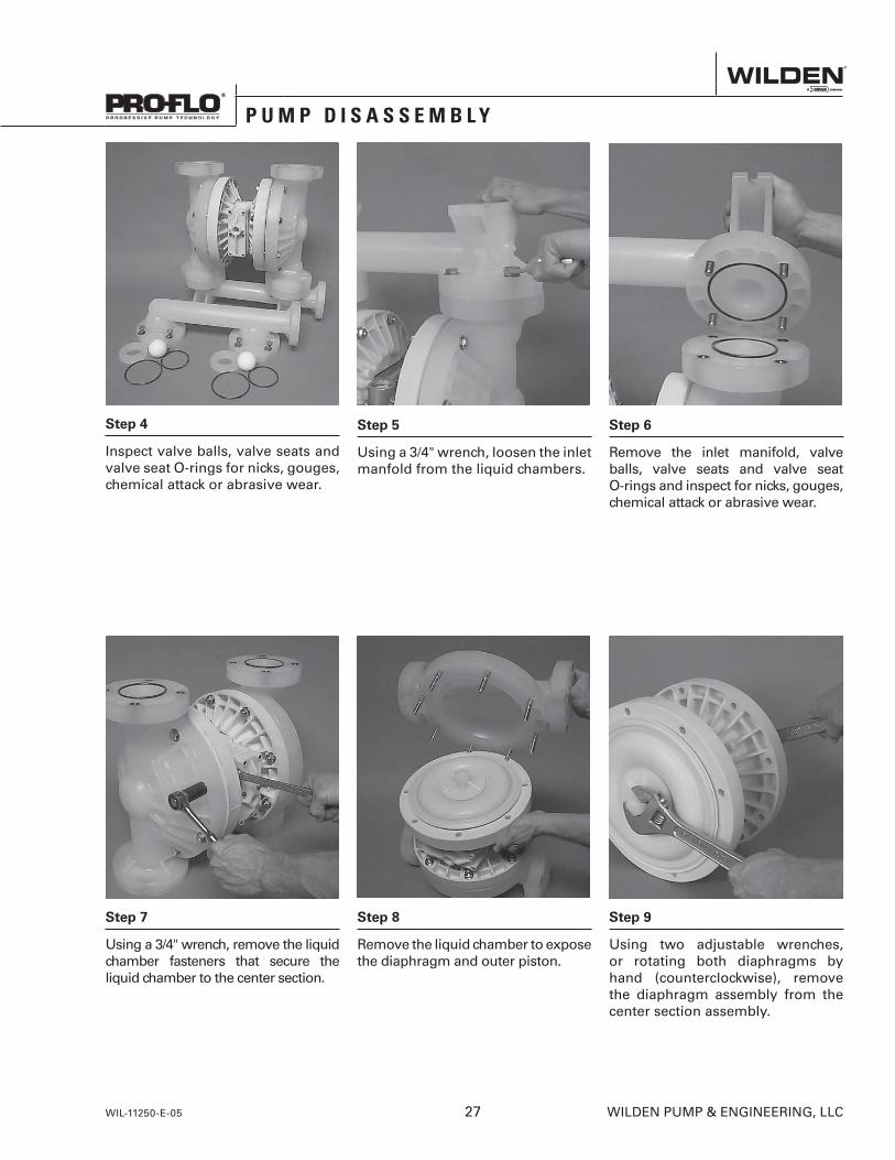
Step 4
Inspect valve balls, valve seats and valve seat O-rings for nicks, gouges, chemical attack or abrasive wear.
Step 5
Using a 3/4" wrench, loosen the inlet manfold from the liquid chambers.
Step 6
Remove the inlet manifold, valve balls, valve seats and valve seat O-rings and inspect for nicks, gouges, chemical attack or abrasive wear.
Step 7
Using a 3/4" wrench, remove the liquid chamber fasteners that secure the liquid chamber to the center section.
Step 8
Remove the liquid chamber to expose the diaphragm and outer piston.
Step 9
Using two adjustable wrenches, or rotating both diaphragms by hand (counterclockwise), remove the diaphragm assembly from the center section assembly.
P U M P D I S A S S E M B L Y
WIL-11250-E-05 27 WILDEN PUMP & ENGINEERING, LLC
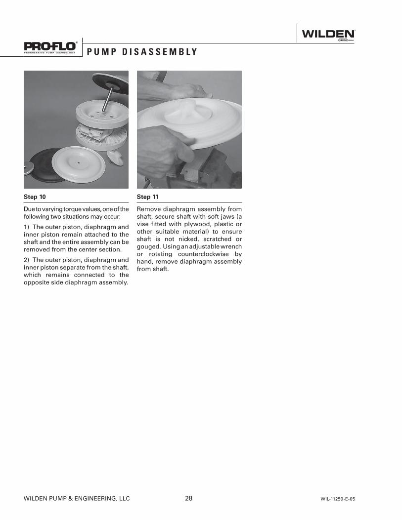
Step 10
Due to varying torque values, one of the following two situations may occur:
1) The outer piston, diaphragm and inner piston remain attached to the shaft and the entire assembly can be removed from the center section.
2) The outer piston, diaphragm and inner piston separate from the shaft, which remains connected to the opposite side diaphragm assembly.
Step 11
Remove diaphragm assembly from shaft, secure shaft with soft jaws (a vise fitted with plywood, plastic or other suitable material) to ensure shaft is not nicked, scratched or gouged. Using an adjustable wrench or rotating counterclockwise by hand, remove diaphragm assembly from shaft.
P U M P D I S A S S E M B L Y
WILDEN PUMP & ENGINEERING, LLC 28 WIL-11250-E-05
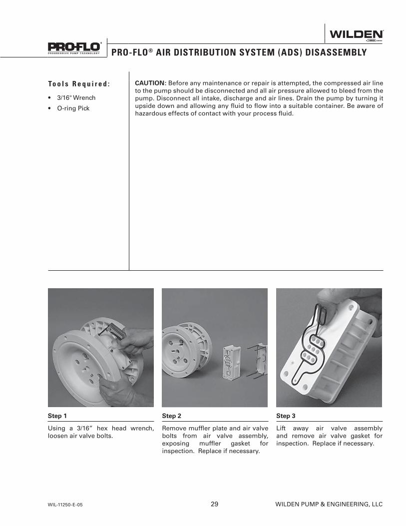
Step 1
Using a 3/16” hex head wrench, loosen air valve bolts.
Step 2
Remove muffler plate and air valve bolts from air valve assembly, exposing muffler gasket for inspection. Replace if necessary.
Step 3
Lift away air valve assembly and remove air valve gasket for inspection. Replace if necessary.
To o l s R e q u i r e d :
• 3/16" Wrench
• O-ring Pick
CAUTION: Before any maintenance or repair is attempted, the compressed air line to the pump should be disconnected and all air pressure allowed to bleed from the pump. Disconnect all intake, discharge and air lines. Drain the pump by turning it upside down and allowing any fluid to flow into a suitable container. Be aware of hazardous effects of contact with your process fluid.
WIL-11250-E-05 29 WILDEN PUMP & ENGINEERING, LLC
S e c t i o n 7 B
PRO-FLO® AIR DISTRIBUTION SYSTEM (ADS) DISASSEMBLY
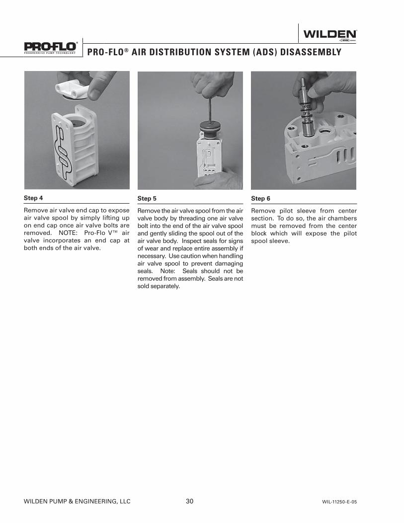
Step 4
Remove air valve end cap to expose air valve spool by simply lifting up on end cap once air valve bolts are removed. NOTE: Pro-Flo V™ air valve incorporates an end cap at both ends of the air valve.
Step 5
Remove the air valve spool from the air valve body by threading one air valve bolt into the end of the air valve spool and gently sliding the spool out of the air valve body. Inspect seals for signs of wear and replace entire assembly if necessary. Use caution when handling air valve spool to prevent damaging seals. Note: Seals should not be removed from assembly. Seals are not sold separately.
Step 6
Remove pilot sleeve from center section. To do so, the air chambers must be removed from the center block which will expose the pilot spool sleeve.
PRO-FLO® AIR DISTRIBUTION SYSTEM (ADS) DISASSEMBLY
WILDEN PUMP & ENGINEERING, LLC 30 WIL-11250-E-05
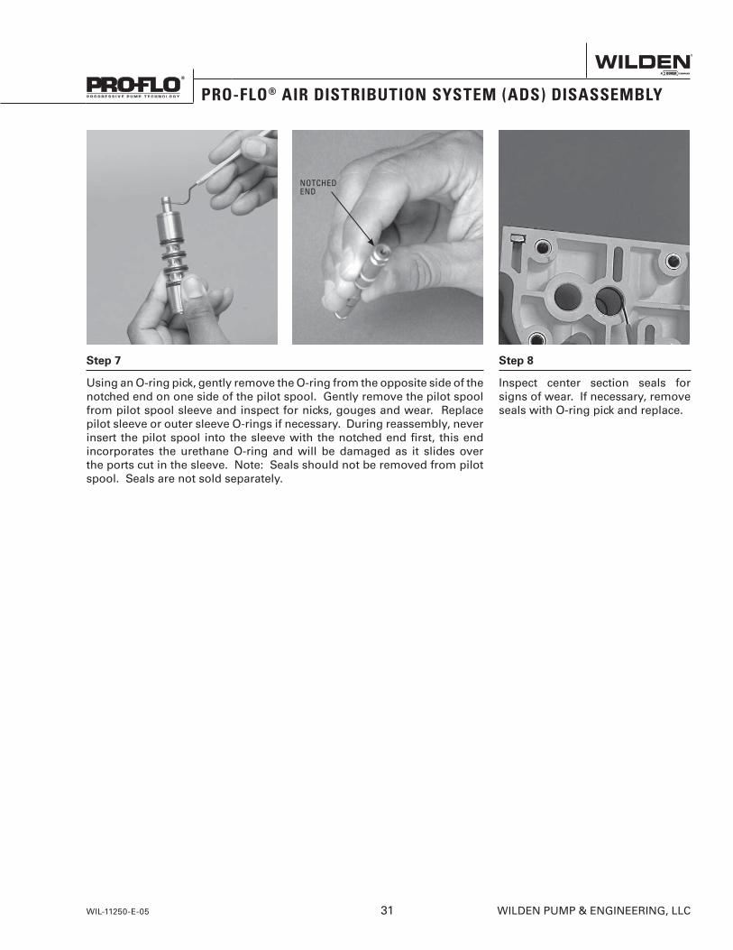
Step 7
Using an O-ring pick, gently remove the O-ring from the opposite side of the notched end on one side of the pilot spool. Gently remove the pilot spool from pilot spool sleeve and inspect for nicks, gouges and wear. Replace pilot sleeve or outer sleeve O-rings if necessary. During reassembly, never insert the pilot spool into the sleeve with the notched end first, this end incorporates the urethane O-ring and will be damaged as it slides over the ports cut in the sleeve. Note: Seals should not be removed from pilot spool. Seals are not sold separately.
Step 8
Inspect center section seals for signs of wear. If necessary, remove seals with O-ring pick and replace.
NOTCHEDEND
PRO-FLO® AIR DISTRIBUTION SYSTEM (ADS) DISASSEMBLY
WIL-11250-E-05 31 WILDEN PUMP & ENGINEERING, LLC
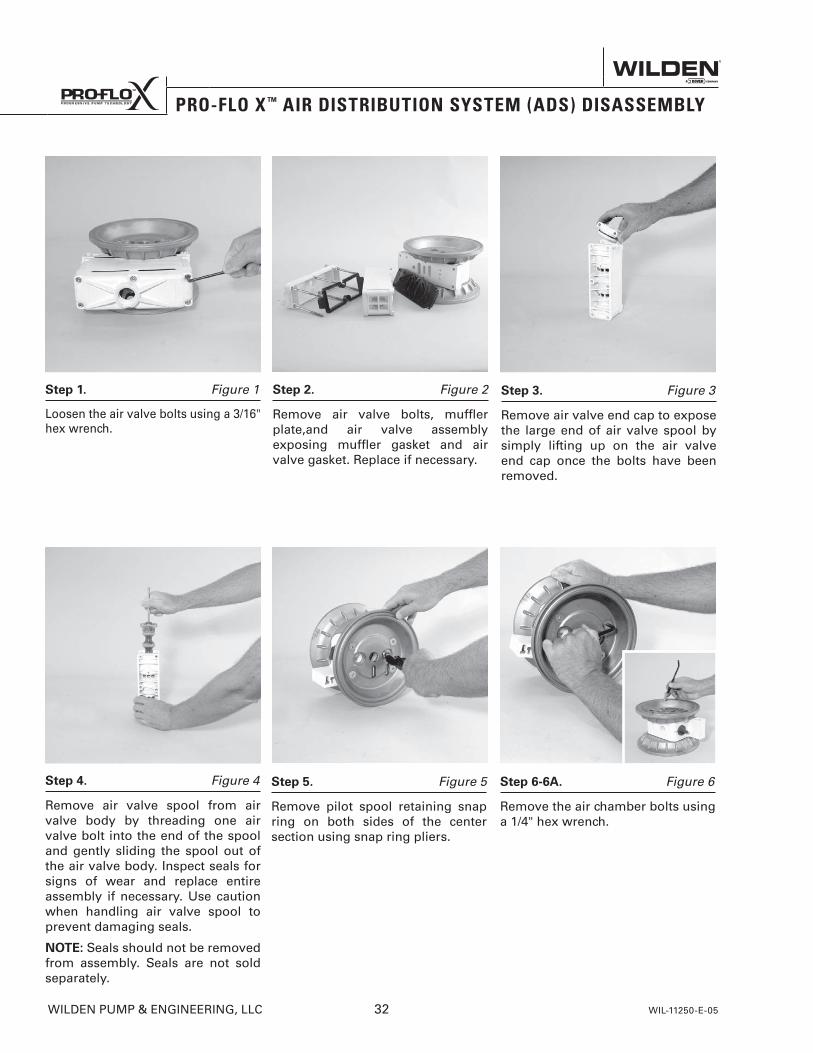
S e c t i o n 7 C
PRO-FLO X ™ AIR DISTRIBUTION SYSTEM (ADS) DISASSEMBLY
Step 1. Figure 1
Loosen the air valve bolts using a 3/16" hex wrench.
Step 2. Figure 2
Remove air valve bolts, muffler plate,and air valve assembly exposing muffler gasket and air valve gasket. Replace if necessary.
Step 3. Figure 3
Remove air valve end cap to expose the large end of air valve spool by simply lifting up on the air valve end cap once the bolts have been removed.
Step 4. Figure 4
Remove air valve spool from air valve body by threading one air valve bolt into the end of the spool and gently sliding the spool out of the air valve body. Inspect seals for signs of wear and replace entire assembly if necessary. Use caution when handling air valve spool to prevent damaging seals.
NOTE: Seals should not be removed from assembly. Seals are not sold separately.
Step 5. Figure 5
Remove pilot spool retaining snap ring on both sides of the center section using snap ring pliers.
Step 6-6A. Figure 6
Remove the air chamber bolts using a 1/4" hex wrench.
WILDEN PUMP & ENGINEERING, LLC 32 WIL-11250-E-05
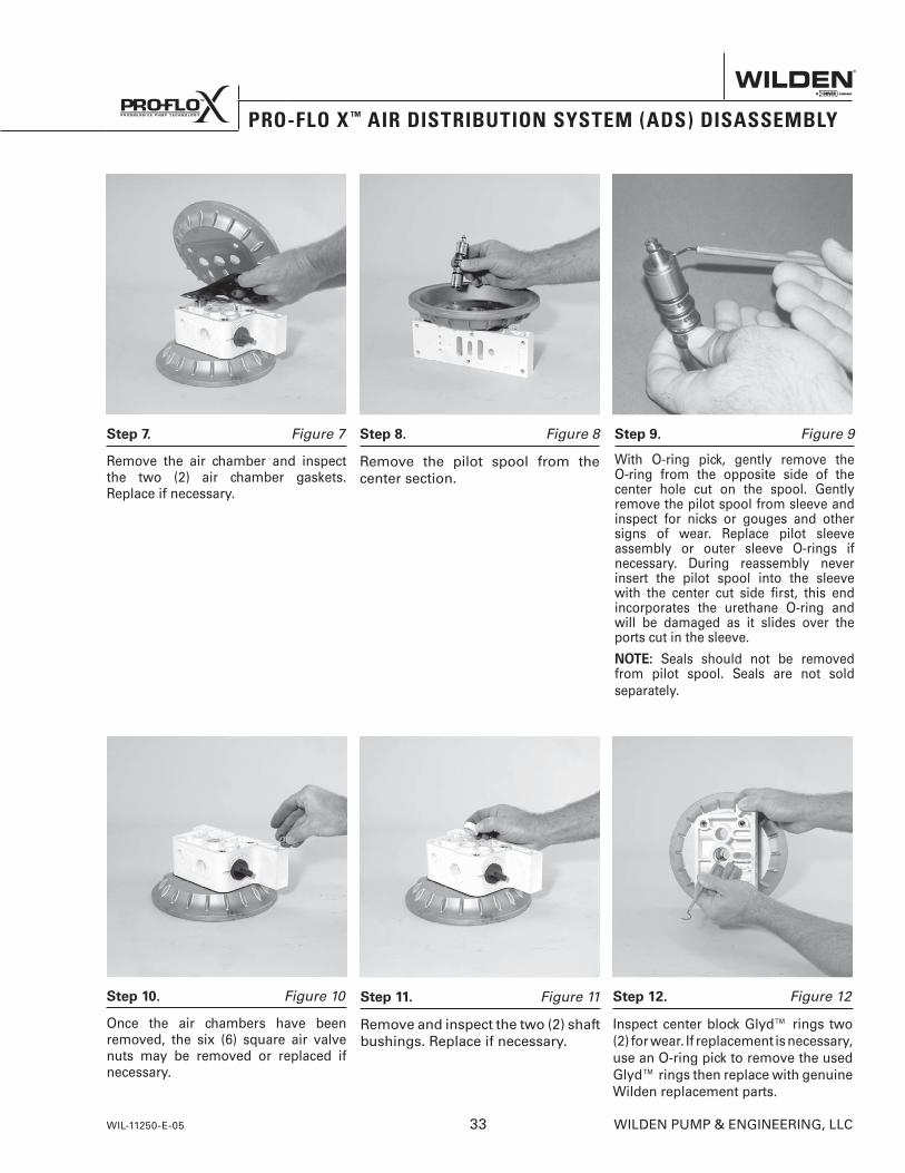
PRO-FLO X ™ AIR DISTRIBUTION SYSTEM (ADS) DISASSEMBLY
Step 11. Figure 11
Remove and inspect the two (2) shaft bushings. Replace if necessary.
Step 12. Figure 12
Inspect center block Glyd™ rings two (2) for wear. If replacement is necessary, use an O-ring pick to remove the used Glyd™ rings then replace with genuine Wilden replacement parts.
Step 7. Figure 7
Remove the air chamber and inspect the two (2) air chamber gaskets. Replace if necessary.
Step 8. Figure 8
Remove the pilot spool from the center section.
Step 9. Figure 9
With O-ring pick, gently remove the O-ring from the opposite side of the center hole cut on the spool. Gently remove the pilot spool from sleeve and inspect for nicks or gouges and other signs of wear. Replace pilot sleeve assembly or outer sleeve O-rings if necessary. During reassembly never insert the pilot spool into the sleeve with the center cut side first, this end incorporates the urethane O-ring and will be damaged as it slides over the ports cut in the sleeve.
NOTE: Seals should not be removed from pilot spool. Seals are not sold separately.
Step 10. Figure 10
Once the air chambers have been removed, the six (6) square air valve nuts may be removed or replaced if necessary.
WIL-11250-E-05 33 WILDEN PUMP & ENGINEERING, LLC
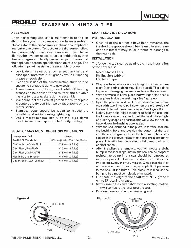
ASSEMBLY:
Upon performing applicable maintenance to the air distribution system, the pump can now be reassembled. Please refer to the disassembly instructions for photos and parts placement. To reassemble the pump, follow the disassembly instructions in reverse order. The air distribution system needs to be assembled first, then the diaphragms and finally the wetted path. Please find the applicable torque specifications on this page. The following tips will assist in the assembly process.
• Lubricate air valve bore, center section shaft and pilot spool bore with NLGI grade 2 white EP bearing grease or equivalent.
• Clean the inside of the center section shaft bore to ensure no damage is done to new seals.
• A small amount of NLGI grade 2 white EP bearing grease can be applied to the muffler and air valve gaskets to locate gaskets during assembly.
• Make sure that the exhaust port on the muffler plate is centered between the two exhaust ports on the center section.
• Stainless bolts should be lubed to reduce the possibility of seizing during tightening.
• Use a mallet to tamp lightly on the large clamp bands to seat the diaphragm before tightening.
SHAFT SEAL INSTALLATION:
PRE-INSTALLATION
• Once all of the old seals have been removed, the inside of the groove should be cleaned to ensure no debris is left that may cause premature damage to the new seals.
INSTALLATION
The following tools can be used to aid in the installation of the new seals:
Needle Nose Pliers Phillips Screwdriver Electrical Tape
• Wrap electrical tape around each leg of the needle nose pliers (heat shrink tubing may also be used). This is done to prevent damaging the inside surface of the new seal.
• With a new seal in hand, place the two legs of the needle nose pliers inside the seal ring. (See Figure A.)
• Open the pliers as wide as the seal diameter will allow, then with two fingers pull down on the top portion of the seal to form kidney bean shape. (See Figure B.)
• Lightly clamp the pliers together to hold the seal into the kidney shape. Be sure to pull the seal into as tight of a kidney shape as possible, this will allow the seal to travel down the bushing bore easier.
• With the seal clamped in the pliers, insert the seal into the bushing bore and position the bottom of the seal into the correct groove. Once the bottom of the seal is seated in the groove, release the clamp pressure on the pliers. This will allow the seal to partially snap back to its original shape.
• After the pliers are removed, you will notice a slight bump in the seal shape. Before the seal can be properly resized, the bump in the seal should be removed as much as possible. This can be done with either the Phillips screwdriver or your finger. With either the side of the screwdriver or your finger, apply light pressure to the peak of the bump. This pressure will cause the bump to be almost completely eliminated.
• Lubricate the edge of the shaft with NLGI grade 2 white EP bearing grease.
• Slowly insert the center shaft with a rotating motion. This will complete the resizing of the seal.
• Perform these steps for the remaining seal.
Figure A
SHAFT SEAL
TAPE
Figure B
SHAFT SEAL
TAPE
NEEDLE NOSE PLIERS
PRO-FLO® MAXIMUM TORQUE SPECIFICATIONSDescription of Part Torque
Pro-Flo® Air Valve Bolts P800 5.1 N•m (45 in-lbs) / PX800 5.1 N•m (45 in-lbs)
Air Chamber to Center Block 27.1 N•m (20 ft-lbs)
Outer Piston, Ultra-Flex™ 47.5 N•m (35 ft-lbs)
Outer Piston, Rubber & TPE 81.3 N•m (60 ft-lbs)
Manifold to Liquid Chamber 44.7 N•m (33 ft-lbs)
Liquid Chamber to Air Chamber 44.7 N•m (33 ft-lbs)
S e c t i o n 7
R E A S S E M B L Y H I N T S & T I P S
WILDEN PUMP & ENGINEERING, LLC 34 WIL-11250-E-05

N O T E S
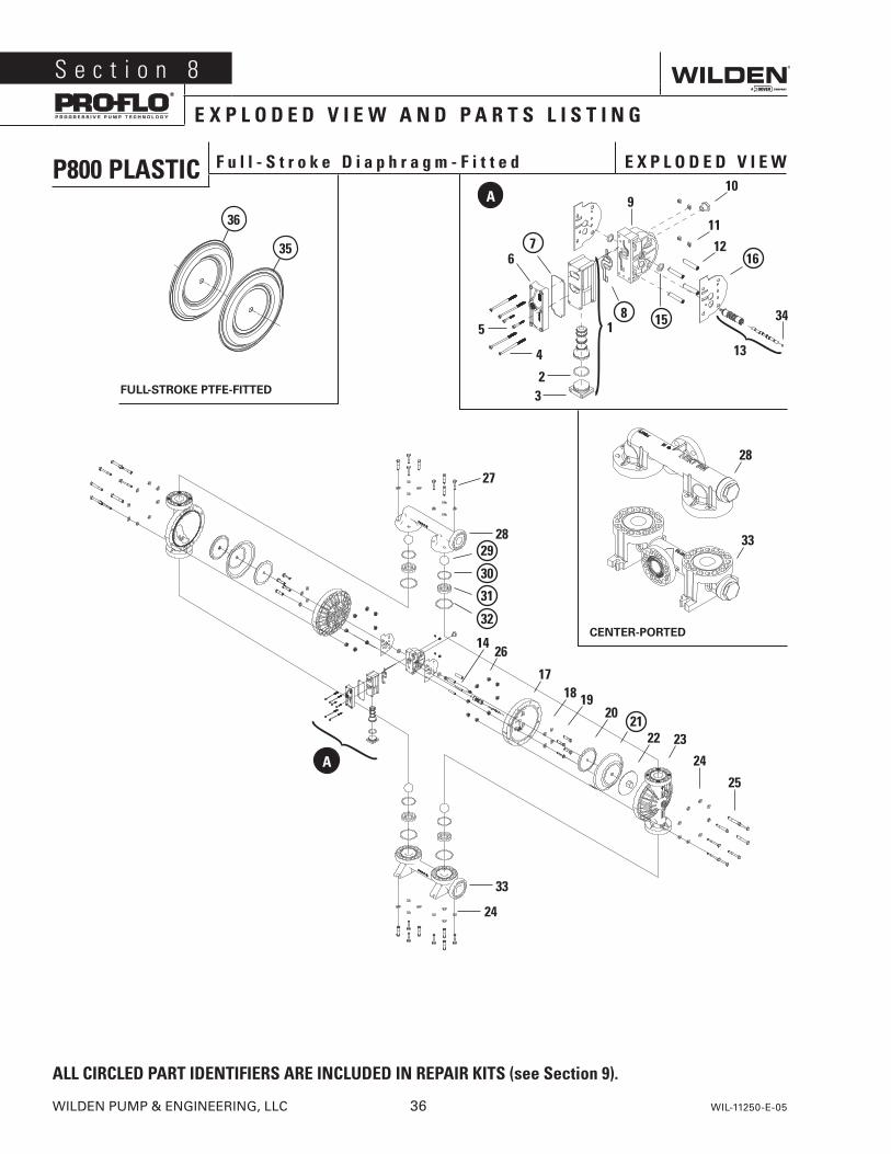
P800 PLASTIC F u l l - S t r o k e D i a p h r a g m - F i t t e d E X P L O D E D V I E W
S e c t i o n 8
E X P L O D E D V I E W A N D P A R T S L I S T I N G
WILDEN PUMP & ENGINEERING, LLC 36 WIL-11250-E-05
ALL CIRCLED PART IDENTIFIERS ARE INCLUDED IN REPAIR KITS (see Section 9).
FULL-STROKE PTFE-FITTED
CENTER-PORTED
4
32
5
67
15
9
81
10
1112
16
13
A
34
28
33
27
2829
30
31
32
33
24
1426
17
24
25
18 1920
2122 23
A
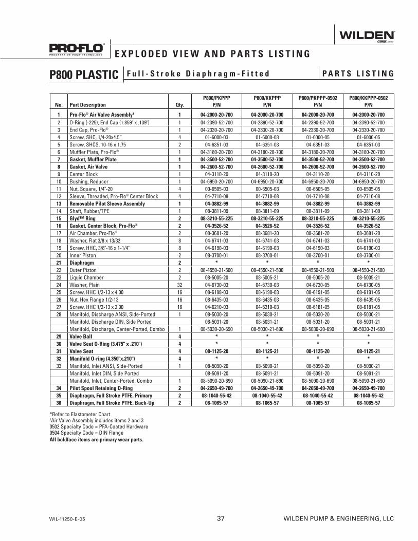
No. Part Description Qty. P800/PKPPP
P/NP800/KKPPP
P/NP800/PKPPP-0502
P/NP800/KKPPP-0502
P/N
1 Pro-Flo® Air Valve Assembly1 1 04-2000-20-700 04-2000-20-700 04-2000-20-700 04-2000-20-7002 O-Ring (-225), End Cap (1.859" x .139") 1 04-2390-52-700 04-2390-52-700 04-2390-52-700 04-2390-52-7003 End Cap, Pro-Flo® 1 04-2330-20-700 04-2330-20-700 04-2330-20-700 04-2330-20-7004 Screw, SHC, 1/4-20x4.5” 4 01-6000-03 01-6000-03 01-6000-05 01-6000-055 Screw, SHCS, 10-16 x 1.75 2 04-6351-03 04-6351-03 04-6351-03 04-6351-036 Muffler Plate, Pro-Flo® 1 04-3180-20-700 04-3180-20-700 04-3180-20-700 04-3180-20-7007 Gasket, Muffler Plate 1 04-3500-52-700 04-3500-52-700 04-3500-52-700 04-3500-52-7008 Gasket, Air Valve 1 04-2600-52-700 04-2600-52-700 04-2600-52-700 04-2600-52-7009 Center Block 1 04-3110-20 04-3110-20 04-3110-20 04-3110-2010 Bushing, Reducer 1 04-6950-20-700 04-6950-20-700 04-6950-20-700 04-6950-20-70011 Nut, Square, 1/4"-20 4 00-6505-03 00-6505-03 00-6505-05 00-6505-0512 Sleeve, Threaded, Pro-Flo® Center Block 4 04-7710-08 04-7710-08 04-7710-08 04-7710-0813 Removable Pilot Sleeve Assembly 1 04-3882-99 04-3882-99 04-3882-99 04-3882-9914 Shaft, Rubber/TPE 1 08-3811-09 08-3811-09 08-3811-09 08-3811-0915 Glyd™ Ring 2 08-3210-55-225 08-3210-55-225 08-3210-55-225 08-3210-55-22516 Gasket, Center Block, Pro-Flo® 2 04-3526-52 04-3526-52 04-3526-52 04-3526-5217 Air Chamber, Pro-Flo® 2 08-3681-20 08-3681-20 08-3681-20 08-3681-2018 Washer, Flat 3/8 x 13/32 8 04-6741-03 04-6741-03 04-6741-03 04-6741-0319 Screw, HHC, 3/8"-16 x 1-1/4" 8 04-6190-03 04-6190-03 04-6190-03 04-6190-0320 Inner Piston 2 08-3700-01 08-3700-01 08-3700-01 08-3700-0121 Diaphragm 2 * * * *22 Outer Piston 2 08-4550-21-500 08-4550-21-500 08-4550-21-500 08-4550-21-50023 Liquid Chamber 2 08-5005-20 08-5005-21 08-5005-20 08-5005-2124 Washer, Plain 32 04-6730-03 04-6730-03 04-6730-05 04-6730-0525 Screw, HHC 1/2-13 x 4.00 16 08-6198-03 08-6198-03 08-6191-05 08-6191-0526 Nut, Hex Flange 1/2-13 16 08-6435-03 08-6435-03 08-6435-05 08-6435-0527 Screw, HHC 1/2-13 x 2.00 16 04-6210-03 04-6210-03 08-6181-05 08-6181-0528 Manifold, Discharge ANSI, Side-Ported 1 08-5030-20 08-5030-21 08-5030-20 08-5030-21
Manifold, Discharge DIN, Side Ported 08-5031-20 08-5031-21 08-5031-20 08-5031-21Manifold, Discharge, Center-Ported, Combo 1 08-5030-20-690 08-5030-21-690 08-5030-20-690 08-5030-21-690
29 Valve Ball 4 * * * *30 Valve Seat O-Ring (3.475" x .210") 4 * * * *31 Valve Seat 4 08-1125-20 08-1125-21 08-1125-20 08-1125-2132 Manifold O-ring (4.350"x.210") 4 * * * *33 Manifold, Inlet ANSI, Side-Ported 1 08-5090-20 08-5090-21 08-5090-20 08-5090-21
Manifold, Inlet DIN, Side Ported 08-5091-20 08-5091-21 08-5091-20 08-5091-21Manifold, Inlet, Center-Ported, Combo 1 08-5090-20-690 08-5090-21-690 08-5090-20-690 08-5090-21-690
34 Pilot Spool Retaining O-Ring 2 04-2650-49-700 04-2650-49-700 04-2650-49-700 04-2650-49-70035 Diaphragm, Full Stroke PTFE, Primary 2 08-1040-55-42 08-1040-55-42 08-1040-55-42 08-1040-55-4236 Diaphragm, Full Stroke PTFE, Back-Up 2 08-1065-57 08-1065-57 08-1065-57 08-1065-57
*Refer to Elastometer Chart 1Air Valve Assembly includes items 2 and 30502 Specialty Code = PFA-Coated Hardware0504 Specialty Code = DIN FlangeAll boldface items are primary wear parts.
E X P L O D E D V I E W A N D P A R T S L I S T I N G
P800 PLASTIC F u l l - S t r o k e D i a p h r a g m - F i t t e d P A R T S L I S T I N G
WIL-11250-E-05 37 WILDEN PUMP & ENGINEERING, LLC
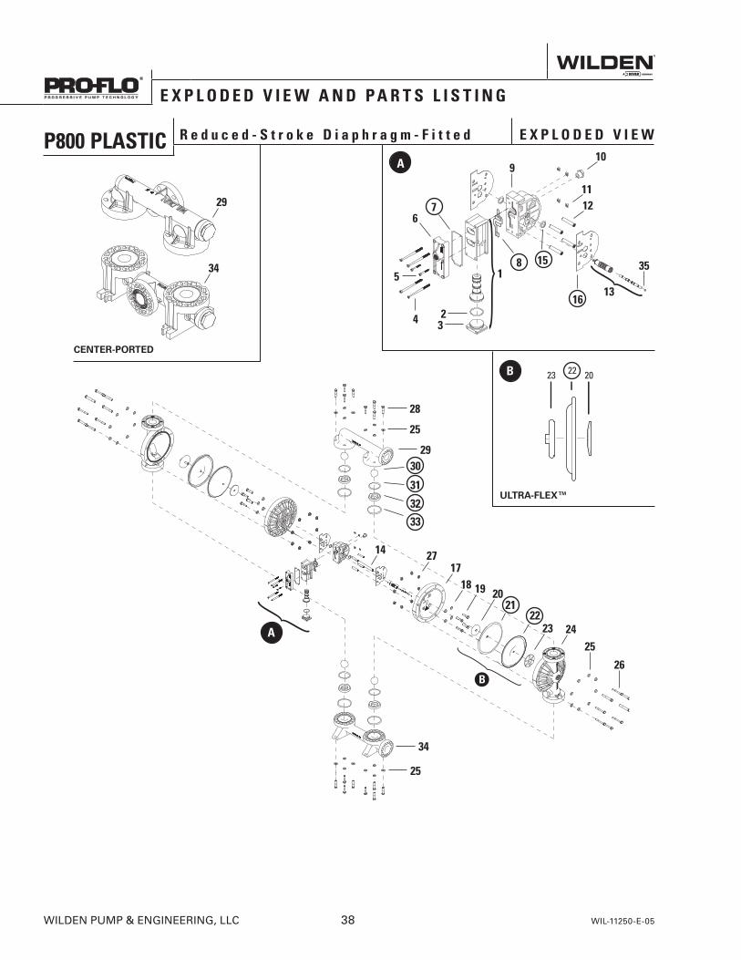
28
25
2930
31
32
33
34
25
25
26
14 2717
18 19 2021
2223 24A
E X P L O D E D V I E W A N D P A R T S L I S T I N G
P800 PLASTIC R e d u c e d - S t r o k e D i a p h r a g m - F i t t e d E X P L O D E D V I E W
WILDEN PUMP & ENGINEERING, LLC 38 WIL-11250-E-05
ULTRA-FLEX™
CENTER-PORTED
B
A
4 32
5
67
8
16
115
910
1112
13
35
29
34
23 2022
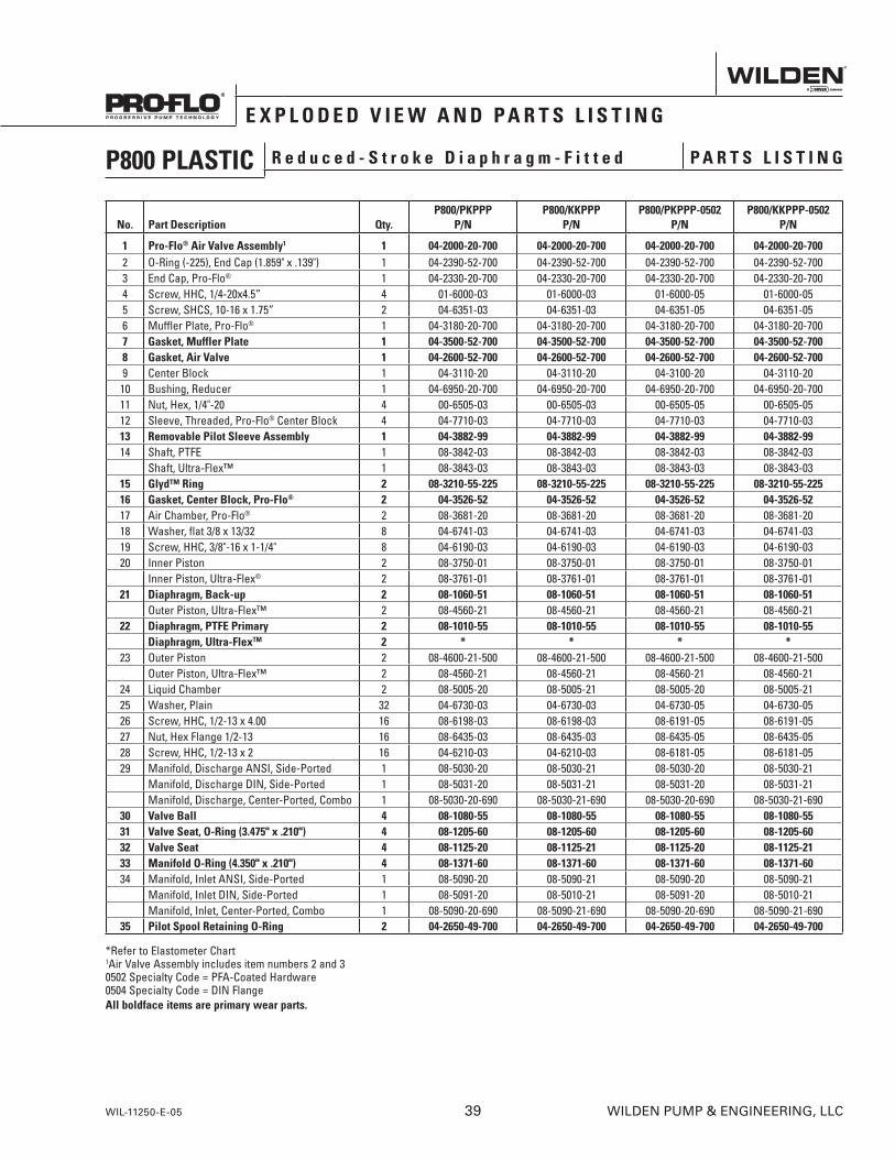
E X P L O D E D V I E W A N D P A R T S L I S T I N G
No. Part Description Qty.P800/PKPPP
P/NP800/KKPPP
P/NP800/PKPPP-0502
P/NP800/KKPPP-0502
P/N
1 Pro-Flo® Air Valve Assembly1 1 04-2000-20-700 04-2000-20-700 04-2000-20-700 04-2000-20-7002 O-Ring (-225), End Cap (1.859" x .139") 1 04-2390-52-700 04-2390-52-700 04-2390-52-700 04-2390-52-7003 End Cap, Pro-Flo® 1 04-2330-20-700 04-2330-20-700 04-2330-20-700 04-2330-20-7004 Screw, HHC, 1/4-20x4.5” 4 01-6000-03 01-6000-03 01-6000-05 01-6000-055 Screw, SHCS, 10-16 x 1.75” 2 04-6351-03 04-6351-03 04-6351-05 04-6351-056 Muffler Plate, Pro-Flo® 1 04-3180-20-700 04-3180-20-700 04-3180-20-700 04-3180-20-7007 Gasket, Muffler Plate 1 04-3500-52-700 04-3500-52-700 04-3500-52-700 04-3500-52-7008 Gasket, Air Valve 1 04-2600-52-700 04-2600-52-700 04-2600-52-700 04-2600-52-7009 Center Block 1 04-3110-20 04-3110-20 04-3100-20 04-3110-2010 Bushing, Reducer 1 04-6950-20-700 04-6950-20-700 04-6950-20-700 04-6950-20-70011 Nut, Hex, 1/4"-20 4 00-6505-03 00-6505-03 00-6505-05 00-6505-0512 Sleeve, Threaded, Pro-Flo® Center Block 4 04-7710-03 04-7710-03 04-7710-03 04-7710-0313 Removable Pilot Sleeve Assembly 1 04-3882-99 04-3882-99 04-3882-99 04-3882-9914 Shaft, PTFE 1 08-3842-03 08-3842-03 08-3842-03 08-3842-03
Shaft, Ultra-Flex™ 1 08-3843-03 08-3843-03 08-3843-03 08-3843-0315 Glyd™ Ring 2 08-3210-55-225 08-3210-55-225 08-3210-55-225 08-3210-55-22516 Gasket, Center Block, Pro-Flo® 2 04-3526-52 04-3526-52 04-3526-52 04-3526-5217 Air Chamber, Pro-Flo® 2 08-3681-20 08-3681-20 08-3681-20 08-3681-2018 Washer, flat 3/8 x 13/32 8 04-6741-03 04-6741-03 04-6741-03 04-6741-0319 Screw, HHC, 3/8"-16 x 1-1/4" 8 04-6190-03 04-6190-03 04-6190-03 04-6190-0320 Inner Piston 2 08-3750-01 08-3750-01 08-3750-01 08-3750-01
Inner Piston, Ultra-Flex® 2 08-3761-01 08-3761-01 08-3761-01 08-3761-0121 Diaphragm, Back-up 2 08-1060-51 08-1060-51 08-1060-51 08-1060-51
Outer Piston, Ultra-Flex™ 2 08-4560-21 08-4560-21 08-4560-21 08-4560-2122 Diaphragm, PTFE Primary 2 08-1010-55 08-1010-55 08-1010-55 08-1010-55
Diaphragm, Ultra-FlexTM 2 * * * *23 Outer Piston 2 08-4600-21-500 08-4600-21-500 08-4600-21-500 08-4600-21-500
Outer Piston, Ultra-Flex™ 2 08-4560-21 08-4560-21 08-4560-21 08-4560-2124 Liquid Chamber 2 08-5005-20 08-5005-21 08-5005-20 08-5005-2125 Washer, Plain 32 04-6730-03 04-6730-03 04-6730-05 04-6730-0526 Screw, HHC, 1/2-13 x 4.00 16 08-6198-03 08-6198-03 08-6191-05 08-6191-0527 Nut, Hex Flange 1/2-13 16 08-6435-03 08-6435-03 08-6435-05 08-6435-0528 Screw, HHC, 1/2-13 x 2 16 04-6210-03 04-6210-03 08-6181-05 08-6181-0529 Manifold, Discharge ANSI, Side-Ported 1 08-5030-20 08-5030-21 08-5030-20 08-5030-21
Manifold, Discharge DIN, Side-Ported 1 08-5031-20 08-5031-21 08-5031-20 08-5031-21Manifold, Discharge, Center-Ported, Combo 1 08-5030-20-690 08-5030-21-690 08-5030-20-690 08-5030-21-690
30 Valve Ball 4 08-1080-55 08-1080-55 08-1080-55 08-1080-5531 Valve Seat, O-Ring (3.475" x .210") 4 08-1205-60 08-1205-60 08-1205-60 08-1205-6032 Valve Seat 4 08-1125-20 08-1125-21 08-1125-20 08-1125-2133 Manifold O-Ring (4.350" x .210") 4 08-1371-60 08-1371-60 08-1371-60 08-1371-6034 Manifold, Inlet ANSI, Side-Ported 1 08-5090-20 08-5090-21 08-5090-20 08-5090-21
Manifold, Inlet DIN, Side-Ported 1 08-5091-20 08-5010-21 08-5091-20 08-5010-21Manifold, Inlet, Center-Ported, Combo 1 08-5090-20-690 08-5090-21-690 08-5090-20-690 08-5090-21-690
35 Pilot Spool Retaining O-Ring 2 04-2650-49-700 04-2650-49-700 04-2650-49-700 04-2650-49-700
*Refer to Elastometer Chart 1Air Valve Assembly includes item numbers 2 and 30502 Specialty Code = PFA-Coated Hardware0504 Specialty Code = DIN FlangeAll boldface items are primary wear parts.
P800 PLASTIC R e d u c e d - S t r o k e D i a p h r a g m - F i t t e d P A R T S L I S T I N G
WIL-11250-E-05 39 WILDEN PUMP & ENGINEERING, LLC
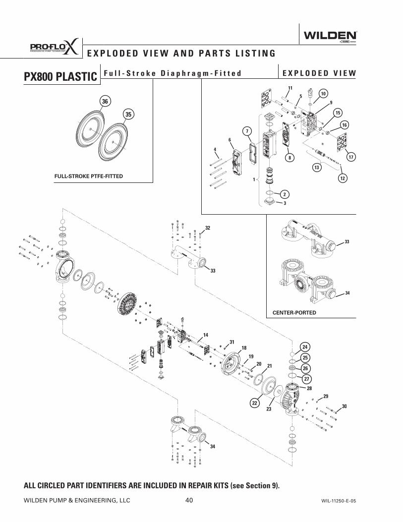
PX800 PLASTIC F u l l - S t r o k e D i a p h r a g m - F i t t e d E X P L O D E D V I E W
E X P L O D E D V I E W A N D P A R T S L I S T I N G
WILDEN PUMP & ENGINEERING, LLC 40 WIL-11250-E-05
CENTER-PORTED
FULL-STROKE PTFE-FITTED
ALL CIRCLED PART IDENTIFIERS ARE INCLUDED IN REPAIR KITS (see Section 9).
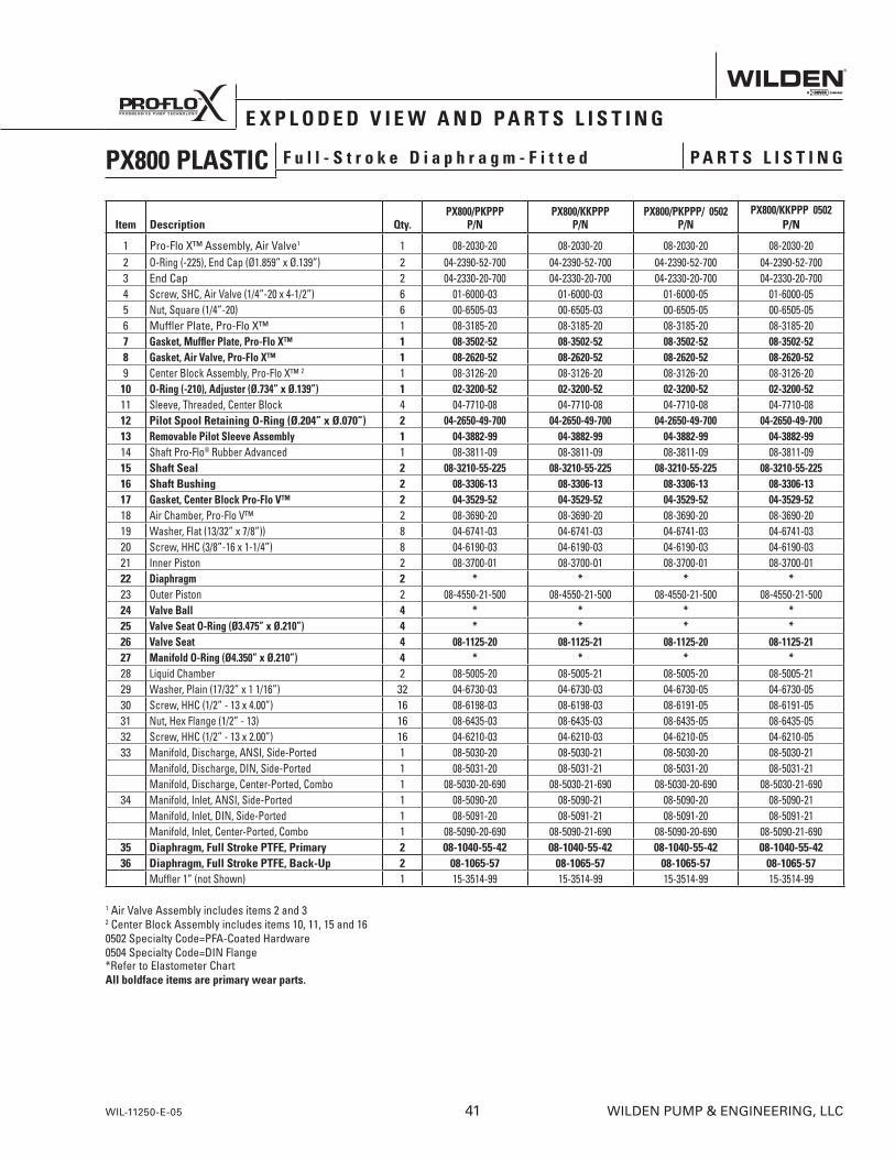
PX800 PLASTIC F u l l - S t r o k e D i a p h r a g m - F i t t e d P A R T S L I S T I N G
Item Description Qty.PX800/PKPPP
P/NPX800/KKPPP
P/NPX800/PKPPP/ 0502
P/NPX800/KKPPP 0502
P/N
1 Pro-Flo X™ Assembly, Air Valve1 1 08-2030-20 08-2030-20 08-2030-20 08-2030-202 O-Ring (-225), End Cap (Ø1.859” x Ø.139”) 2 04-2390-52-700 04-2390-52-700 04-2390-52-700 04-2390-52-7003 End Cap 2 04-2330-20-700 04-2330-20-700 04-2330-20-700 04-2330-20-7004 Screw, SHC, Air Valve (1/4”-20 x 4-1/2”) 6 01-6000-03 01-6000-03 01-6000-05 01-6000-055 Nut, Square (1/4”-20) 6 00-6505-03 00-6505-03 00-6505-05 00-6505-056 Muffler Plate, Pro-Flo X™ 1 08-3185-20 08-3185-20 08-3185-20 08-3185-207 Gasket, Muffler Plate, Pro-Flo X™ 1 08-3502-52 08-3502-52 08-3502-52 08-3502-528 Gasket, Air Valve, Pro-Flo X™ 1 08-2620-52 08-2620-52 08-2620-52 08-2620-529 Center Block Assembly, Pro-Flo X™ 2 1 08-3126-20 08-3126-20 08-3126-20 08-3126-2010 O-Ring (-210), Adjuster (Ø.734” x Ø.139”) 1 02-3200-52 02-3200-52 02-3200-52 02-3200-5211 Sleeve, Threaded, Center Block 4 04-7710-08 04-7710-08 04-7710-08 04-7710-0812 Pilot Spool Retaining O-Ring (Ø.204” x Ø.070”) 2 04-2650-49-700 04-2650-49-700 04-2650-49-700 04-2650-49-70013 Removable Pilot Sleeve Assembly 1 04-3882-99 04-3882-99 04-3882-99 04-3882-9914 Shaft Pro-Flo® Rubber Advanced 1 08-3811-09 08-3811-09 08-3811-09 08-3811-0915 Shaft Seal 2 08-3210-55-225 08-3210-55-225 08-3210-55-225 08-3210-55-22516 Shaft Bushing 2 08-3306-13 08-3306-13 08-3306-13 08-3306-1317 Gasket, Center Block Pro-Flo V™ 2 04-3529-52 04-3529-52 04-3529-52 04-3529-5218 Air Chamber, Pro-Flo V™ 2 08-3690-20 08-3690-20 08-3690-20 08-3690-2019 Washer, Flat (13/32” x 7/8”)) 8 04-6741-03 04-6741-03 04-6741-03 04-6741-0320 Screw, HHC (3/8”-16 x 1-1/4”) 8 04-6190-03 04-6190-03 04-6190-03 04-6190-0321 Inner Piston 2 08-3700-01 08-3700-01 08-3700-01 08-3700-0122 Diaphragm 2 * * * *23 Outer Piston 2 08-4550-21-500 08-4550-21-500 08-4550-21-500 08-4550-21-50024 Valve Ball 4 * * * *25 Valve Seat O-Ring (Ø3.475” x Ø.210”) 4 * * * *26 Valve Seat 4 08-1125-20 08-1125-21 08-1125-20 08-1125-2127 Manifold O-Ring (Ø4.350” x Ø.210”) 4 * * * *28 Liquid Chamber 2 08-5005-20 08-5005-21 08-5005-20 08-5005-2129 Washer, Plain (17/32” x 1 1/16”) 32 04-6730-03 04-6730-03 04-6730-05 04-6730-0530 Screw, HHC (1/2” - 13 x 4.00”) 16 08-6198-03 08-6198-03 08-6191-05 08-6191-0531 Nut, Hex Flange (1/2” - 13) 16 08-6435-03 08-6435-03 08-6435-05 08-6435-0532 Screw, HHC (1/2” - 13 x 2.00”) 16 04-6210-03 04-6210-03 04-6210-05 04-6210-0533 Manifold, Discharge, ANSI, Side-Ported 1 08-5030-20 08-5030-21 08-5030-20 08-5030-21
Manifold, Discharge, DIN, Side-Ported 1 08-5031-20 08-5031-21 08-5031-20 08-5031-21Manifold, Discharge, Center-Ported, Combo 1 08-5030-20-690 08-5030-21-690 08-5030-20-690 08-5030-21-690
34 Manifold, Inlet, ANSI, Side-Ported 1 08-5090-20 08-5090-21 08-5090-20 08-5090-21Manifold, Inlet, DIN, Side-Ported 1 08-5091-20 08-5091-21 08-5091-20 08-5091-21Manifold, Inlet, Center-Ported, Combo 1 08-5090-20-690 08-5090-21-690 08-5090-20-690 08-5090-21-690
35 Diaphragm, Full Stroke PTFE, Primary 2 08-1040-55-42 08-1040-55-42 08-1040-55-42 08-1040-55-4236 Diaphragm, Full Stroke PTFE, Back-Up 2 08-1065-57 08-1065-57 08-1065-57 08-1065-57
Muffler 1” (not Shown) 1 15-3514-99 15-3514-99 15-3514-99 15-3514-99
1 Air Valve Assembly includes items 2 and 3 2 Center Block Assembly includes items 10, 11, 15 and 16 0502 Specialty Code=PFA-Coated Hardware 0504 Specialty Code=DIN Flange*Refer to Elastometer Chart All boldface items are primary wear parts.
E X P L O D E D V I E W A N D P A R T S L I S T I N G
WIL-11250-E-05 41 WILDEN PUMP & ENGINEERING, LLC
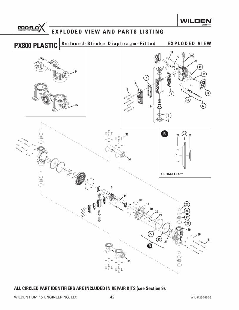
PX800 PLASTIC R e d u c e d - S t r o k e D i a p h r a g m - F i t t e d E X P L O D E D V I E W
E X P L O D E D V I E W A N D P A R T S L I S T I N G
WILDEN PUMP & ENGINEERING, LLC 42 WIL-11250-E-05
ALL CIRCLED PART IDENTIFIERS ARE INCLUDED IN REPAIR KITS (see Section 9).
24 2123B
ULTRA-FLEX™
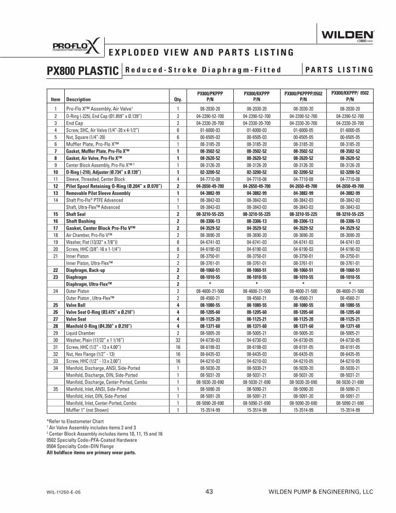
PX800 PLASTIC R e d u c e d - S t r o k e D i a p h r a g m - F i t t e d P A R T S L I S T I N G
*Refer to Elastometer Chart1 Air Valve Assembly includes items 2 and 3 2 Center Block Assembly includes items 10, 11, 15 and 16 0502 Specialty Code=PFA-Coated Hardware 0504 Specialty Code=DIN FlangeAll boldface items are primary wear parts.
Item Description Qty.PX800/PKPPP
P/NPX800/KKPPP
P/NPX800/PKPPPP/0502
P/NPX800/KKPPP/ 0502
P/N
1 Pro-Flo X™ Assembly, Air Valve1 1 08-2030-20 08-2030-20 08-2030-20 08-2030-202 O-Ring (-225), End Cap (Ø1.859” x Ø.139”) 2 04-2390-52-700 04-2390-52-700 04-2390-52-700 04-2390-52-7003 End Cap 2 04-2330-20-700 04-2330-20-700 04-2330-20-700 04-2330-20-7004 Screw, SHC, Air Valve (1/4”-20 x 4-1/2”) 6 01-6000-03 01-6000-03 01-6000-05 01-6000-055 Nut, Square (1/4”-20) 6 00-6505-03 00-6505-03 00-6505-05 00-6505-056 Muffler Plate, Pro-Flo X™ 1 08-3185-20 08-3185-20 08-3185-20 08-3185-207 Gasket, Muffler Plate, Pro-Flo X™ 1 08-3502-52 08-3502-52 08-3502-52 08-3502-528 Gasket, Air Valve, Pro-Flo X™ 1 08-2620-52 08-2620-52 08-2620-52 08-2620-529 Center Block Assembly, Pro-Flo X™ 2 1 08-3126-20 08-3126-20 08-3126-20 08-3126-2010 O-Ring (-210), Adjuster (Ø.734” x Ø.139”) 1 02-3200-52 02-3200-52 02-3200-52 02-3200-5211 Sleeve, Threaded, Center Block 4 04-7710-08 04-7710-08 04-7710-08 04-7710-0812 Pilot Spool Retaining O-Ring (Ø.204” x Ø.070”) 2 04-2650-49-700 04-2650-49-700 04-2650-49-700 04-2650-49-70013 Removable Pilot Sleeve Assembly 1 04-3882-99 04-3882-99 04-3882-99 04-3882-9914 Shaft Pro-Flo® PTFE Advanced 1 08-3842-03 08-3842-03 08-3842-03 08-3842-03
Shaft, Ultra-Flex™ Advanced 1 08-3843-03 08-3843-03 08-3843-03 08-3843-0315 Shaft Seal 2 08-3210-55-225 08-3210-55-225 08-3210-55-225 08-3210-55-22516 Shaft Bushing 2 08-3306-13 08-3306-13 08-3306-13 08-3306-1317 Gasket, Center Block Pro-Flo V™ 2 04-3529-52 04-3529-52 04-3529-52 04-3529-5218 Air Chamber, Pro-Flo V™ 2 08-3690-20 08-3690-20 08-3690-20 08-3690-2019 Washer, Flat (13/32” x 7/8”)) 8 04-6741-03 04-6741-03 04-6741-03 04-6741-0320 Screw, HHC (3/8”-16 x 1-1/4”) 8 04-6190-03 04-6190-03 04-6190-03 04-6190-0321 Inner Piston 2 08-3750-01 08-3750-01 08-3750-01 08-3750-01
Inner Piston, Ultra-Flex™ 2 08-3761-01 08-3761-01 08-3761-01 08-3761-0122 Diaphragm, Back-up 2 08-1060-51 08-1060-51 08-1060-51 08-1060-5123 Diaphragm 2 08-1010-55 08-1010-55 08-1010-55 08-1010-55
Diaphragm, Ultra-Flex™ 2 * * * *24 Outer Piston 2 08-4600-21-500 08-4600-21-500 08-4600-21-500 08-4600-21-500
Outer Piston , Ultra-Flex™ 2 08-4560-21 08-4560-21 08-4560-21 08-4560-2125 Valve Ball 4 08-1080-55 08-1080-55 08-1080-55 08-1080-5526 Valve Seat O-Ring (Ø3.475” x Ø.210”) 4 08-1205-60 08-1205-60 08-1205-60 08-1205-6027 Valve Seat 4 08-1125-20 08-1125-21 08-1125-20 08-1125-2128 Manifold O-Ring (Ø4.350” x Ø.210”) 4 08-1371-60 08-1371-60 08-1371-60 08-1371-6029 Liquid Chamber 2 08-5005-20 08-5005-21 08-5005-20 08-5005-2130 Washer, Plain (17/32” x 1 1/16”) 32 04-6730-03 04-6730-03 04-6730-05 04-6730-0531 Screw, HHC (1/2” - 13 x 4.00”) 16 08-6198-03 08-6198-03 08-6191-05 08-6191-0532 Nut, Hex Flange (1/2” - 13) 16 08-6435-03 08-6435-03 08-6435-05 08-6435-0533 Screw, HHC (1/2” - 13 x 2.00”) 16 04-6210-03 04-6210-03 04-6210-05 04-6210-0534 Manifold, Discharge, ANSI, Side-Ported 1 08-5030-20 08-5030-21 08-5030-20 08-5030-21
Manifold, Discharge, DIN, Side-Ported 1 08-5031-20 08-5031-21 08-5031-20 08-5031-21Manifold, Discharge, Center-Ported, Combo 1 08-5030-20-690 08-5030-21-690 08-5030-20-690 08-5030-21-690
35 Manifold, Inlet, ANSI, Side-Ported 1 08-5090-20 08-5090-21 08-5090-20 08-5090-21Manifold, Inlet, DIN, Side-Ported 1 08-5091-20 08-5091-21 08-5091-20 08-5091-21Manifold, Inlet, Center-Ported, Combo 1 08-5090-20-690 08-5090-21-690 08-5090-20-690 08-5090-21-690Muffler 1” (not Shown) 1 15-3514-99 15-3514-99 15-3514-99 15-3514-99
E X P L O D E D V I E W A N D P A R T S L I S T I N G
WIL-11250-E-05 43 WILDEN PUMP & ENGINEERING, LLC
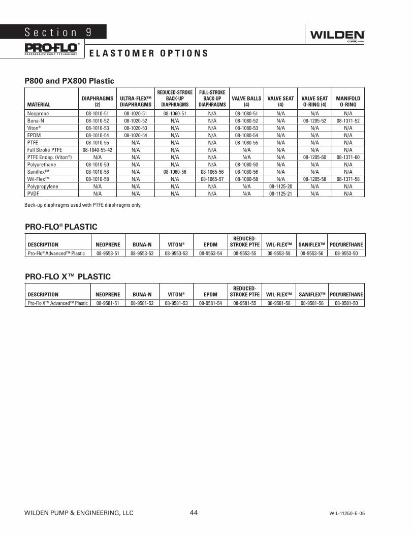
P800 and PX800 Plastic
MATERIALDIAPHRAGMS
(2)ULTRA-FLEX™ DIAPHRAGMS
REDUCED-STROKE BACK-UP
DIAPHRAGMS
FULL-STROKE BACK-UP
DIAPHRAGMSVALVE BALLS
(4)VALVE SEAT
(4)VALVE SEAT O-RING (4)
MANIFOLD O-RING
Neoprene 08-1010-51 08-1020-51 08-1060-51 N/A 08-1080-51 N/A N/A N/ABuna-N 08-1010-52 08-1020-52 N/A N/A 08-1080-52 N/A 08-1205-52 08-1371-52Viton® 08-1010-53 08-1020-53 N/A N/A 08-1080-53 N/A N/A N/AEPDM 08-1010-54 08-1020-54 N/A N/A 08-1080-54 N/A N/A N/APTFE 08-1010-55 N/A N/A N/A 08-1080-55 N/A N/A N/AFull Stroke PTFE 08-1040-55-42 N/A N/A N/A N/A N/A N/A N/APTFE Encap. (Viton®) N/A N/A N/A N/A N/A N/A 08-1205-60 08-1371-60Polyurethane 08-1010-50 N/A N/A N/A 08-1080-50 N/A N/A N/ASaniflex™ 08-1010-56 N/A 08-1060-56 08-1065-56 08-1080-56 N/A N/A N/AWil-Flex™ 08-1010-58 N/A N/A 08-1065-57 08-1080-58 N/A 08-1205-58 08-1371-58Polypropylene N/A N/A N/A N/A N/A 08-1125-20 N/A N/APVDF N/A N/A N/A N/A N/A 08-1125-21 N/A N/A
Back-up diaphragms used with PTFE diaphragms only.
PRO-FLO X™ PLASTIC
DESCRIPTION NEOPRENE BUNA-N VITON® EPDM REDUCED-
STROKE PTFE WIL-FLEX™ SANIFLEX™ POLYURETHANE
Pro-Flo X™ Advanced™ Plastic 08-9581-51 08-9581-52 08-9581-53 08-9581-54 08-9581-55 08-9581-58 08-9581-56 08-9581-50
S e c t i o n 9
E L A S T O M E R O P T I O N S
PRO-FLO® PLASTIC
DESCRIPTION NEOPRENE BUNA-N VITON® EPDM REDUCED-
STROKE PTFE WIL-FLEX™ SANIFLEX™ POLYURETHANE
Pro-Flo® Advanced™ Plastic 08-9553-51 08-9553-52 08-9553-53 08-9553-54 08-9553-55 08-9553-58 08-9553-56 08-9553-50
WILDEN PUMP & ENGINEERING, LLC 44 WIL-11250-E-05
Item # Serial #
Company Where Purchased
Company Name
Industry
Name Title
Street Address
City State Postal Code Country
Telephone Fax E-mail Web Address
Number of pumps in facility? Number of Wilden pumps?
Types of pumps in facility (check all that apply): Diaphragm Centrifugal Gear Submersible Lobe
Other
Media being pumped?
How did you hear of Wilden Pump? Trade Journal Trade Show Internet/E-mail Distributor
Other
P u m P I n f o r m at I o n
PLEaSE PrInt or tYPE anD faX to WILDEn
Yo u r I n f o r m at I o n
onCE ComPLEtE, faX to (909) 783-3440NOTE: WARRANTY VOID IF PAGE IS NOT FAXED TO WILDEN
WILDEN PuMP & ENGINEERING, LLC
W a r r a n t yEach and every product manufactured by Wilden Pump and Engineering, LLC is built to meet the highest standards of quality. Every pump is functionally tested to insure integrity of operation.
Wilden Pump and Engineering, LLC warrants that pumps, accessories and parts manufactured or supplied by it to be free from defects in material and workmanship for a period of five (5) years from date of installation or six (6) years from date of manufacture, whichever comes first. Failure due to normal wear, misapplication, or abuse is, of course, excluded from this warranty.
Since the use of Wilden pumps and parts is beyond our control, we cannot guarantee the suitability of any pump or part for a particular application and Wilden Pump and Engineering, LLC shall not be liable for any consequential damage or expense arising from the use or misuse of its products on any application. Responsibility is limited solely to replacement or repair of defective Wilden pumps and parts.
All decisions as to the cause of failure are the sole determination of Wilden Pump and Engineering, LLC.
Prior approval must be obtained from Wilden for return of any items for warranty consideration and must be accompanied by the appropriate MSDS for the product(s) involved. A Return Goods Tag, obtained from an authorized Wilden distributor, must be included with the items which must be shipped freight prepaid.
The foregoing warranty is exclusive and in lieu of all other warranties expressed or implied (whether written or oral) including all implied warranties of merchantability and fitness for any particular purpose. No distributor or other person is authorized to assume any liability or obligation for Wilden Pump and Engineering, LLC other than expressly provided herein.

22069 Van Buren Street,
Grand Terrace, CA 92313-5607
Telephone: (909) 422-1731
Fax: (909) 783-3440
www.maag.com Copyright 2015, Pump Solutions Group (PSG), A Dover Company
PSG reserves the right to modify the information and illustrations contained in this document without prior notice. This is a non-contractual document. 02-2015
A u t h o r i z e d P S G R e p r e s e n t a t i v e :
Where Innovation Flows
22069 Van Buren St. Grand Terrace, CA 92313-5607
T: +1 (909) 422-1731F: +1 (909) 783-3440