engineering models 1 by: ross king & daniel luddeke
TRANSCRIPT

Engineering Models 1By: Ross King & Daniel Luddeke
Air Foil Project

• The purpose of this project was to create an airfoil cross-sectional sample that had the capability of creating sufficient lift while maintaining low drag.
• The objective of this project was to use balsa wood to create 4 cross sectional cutouts, use manila folder to cover the airfoil and fasten a wooden dowel rod to connect the 4 airfoil cross sectionals with various screw connections in order to perform lift capability tests using a Vernier sensor in a wind tunnel.
Understand

Explore• An airfoil is a structure with curved surfaces designed to give the most
favorable ratio of lift to drag in flight. It is used as the basic form of the wings, fins, and horizontal stabilizer of most aircraft.
• Lift is the force that directly opposes the weight of an object and holds that object in the air. Lift on an aircraft is mostly generated from its airfoils.
• Drag is the aerodynamic force that opposes an aircraft's motion through the air. Drag is generated by every part of the airplane

Explore
• Lift is generated when thrust, a man made force produced normally by an engine, forces the object in a direction. Air is defined as a fluid and as the engine thrust propels the aircraft it increase the motion of this fluid. This increased fluid creates an area of low pressure above the wing and an area of high pressure below the wing. This is caused because the air is more accelerated over the top of the wing creating lower pressure.
• The Higher pressure on the bottom of the wing causes it to rise to the higher temperature. When the aircraft rolls on its lateral axis and creates an angle of attack, the lift to drag ratio increases and the aircraft takes flight.
• Drag is generated when an object on an airfoil creates resistance against the steady flow of air over the airfoil. Drag causes less lift and this must be compensated with increased thrust.
Define
• The requirements and regulations for this project are as followed:
- The length of the airfoil must be shorter than 5in.- The thickness of the airfoil must not exceed an inch.- The airfoil must have 2 screws with 2 washers and 2 bolts
between the two center cross sectional balsa wood cutouts in order to connect the Vernier sensor.
- There must be a total of 4 airfoil cross sectional pieces within the wing in order to give it structure.
- A 4/32 diameter, 5in long wooden dowel rod must run through the head of each airfoil cross sectional and be glued into each hole.

Ideate• There is a wide variety of different airfoil designs and we tested a wide
variety of different camber curvatures, wing areas and thicknesses on NASA’s Foil Sim III Applet.
• Below are a wide variety of different airfoil designs and ideas:
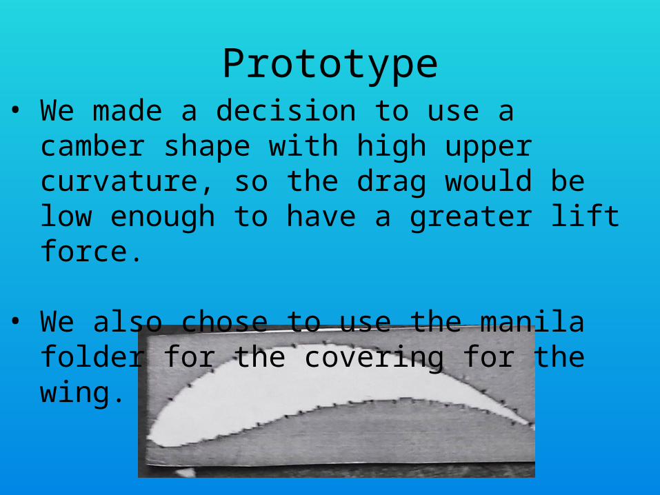
Prototype• We made a decision to use a camber shape with
high upper curvature, so the drag would be low enough to have a greater lift force.
• We also chose to use the manila folder for the covering for the wing.

Solution• Our final airfoil was the same as our prototype and we ran a variety of lift and drag
tests using Vernier sensors in a wind tunnel. The results of our airfoils test runs at an angle of attack of 5, 10 and 20 degrees are listed below (three trails were completed per angle measure):
Trial 1 Trial 2 Trail 3
Drag Mean:.208 NStd:.036 N
Mean:.190 NStd:.067 N
Mean:.216 NStd:.070 N
Lift Mean:.199 NStd:.035 N
Mean:.175 NStd:.070 N
Mean:.187 NStd:.065 N
Trial 1 Trial 2 Trial 3
Drag Mean:.306 NStd:.015 N
Mean:.310 NStd:.014 N
Mean:.311 NStd:.013 N
Lift Mean:.041 NStd:.014 N
Mean :.040 NStd:.015 N
Mean:.045 NStd:.012 N

Solution
Trial 1 Trial 2 Trial 3
Drag Mean:.124 NStd:.047 N
Mean:.092 NStd:.039 N
Mean:.090 NStd:.044 N
Lift Mean:.227 NStd:.081 N
Mean:.190 NStd:.082 N
Mean:.172 NStd:.092 N
Refine
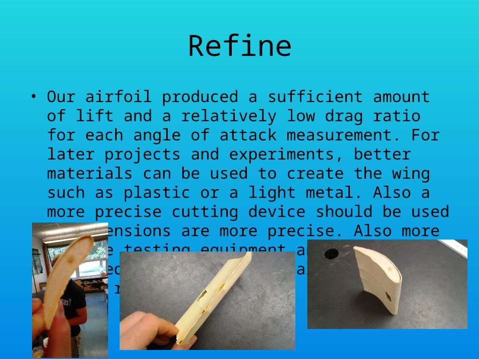
• Our airfoil produced a sufficient amount of lift and a relatively low drag ratio for each angle of attack measurement. For later projects and experiments, better materials can be used to create the wing such as plastic or a light metal. Also a more precise cutting device should be used so dimensions are more precise. Also more precise testing equipment and a more advanced wind tunnel will also yield better results.