engineering standard links... · itp inspection and testing plan lv low voltage, exceeding 32vac or...
TRANSCRIPT

ENGINEERING STANDARD
Electrical Work
Document: GRC-ES001 Revision: 2
REVISION HISTORY
Rev Date Description Prepared By Approved By
1 10/09/2011 Original Issue J. Hickey C. Swanton
2 21/04/2017 Revised and Updated B. James C. Swanton
Copyright © 2016 Gladstone Regional Council. This document is confidential and may contain information proprietary to Gladstone Regional Council. The disclosure, copying or taking action in reliance on or distribution of this document or any information it contains by anyone other than those authorised to do so, in writing, by Gladstone Regional Council is prohibited. This document reflects the requirements of Gladstone Regional Council and may not represent the opinions of the author of this document.

ENGINEERING STANDARD GRC-ES001 – Electrical Work
Revision 2, 12 December 2016 Page 2 of 34
TABLE OF CONTENTS
1 PURPOSE ............................................................................................................................. 5
2 SCOPE .................................................................................................................................. 5
3 RESPONSIBILITIES .............................................................................................................. 5
4 DEFINITIONS ........................................................................................................................ 5
5 REFERENCE DOCUMENTS ................................................................................................. 6
5.1 GRC Engineering Standards......................................................................................... 6
5.2 GRC Standard Drawings .............................................................................................. 6
5.3 Australian Standards .................................................................................................... 7
5.4 Acts and Regulations .................................................................................................... 7
6 GENERAL REQUIREMENTS ................................................................................................ 8
6.1 Health, Safety and Environment ................................................................................... 8
6.2 Low Voltage Insulated Gloves ....................................................................................... 8
6.3 Cables Coated with Asbestos Based Fire Retardant Material ....................................... 8
6.4 Asbestos Based Material in Switchgear Panels ............................................................ 8
6.5 Insulation Material Containing Chrysotile Asbestos Fibres ............................................ 9
6.6 Capacitors Containing PCB’s ........................................................................................ 9
6.7 Prohibited Materials ...................................................................................................... 9
6.8 Site Inductions .............................................................................................................. 9
6.9 Supervision ................................................................................................................... 9
6.10 Personal Protective Equipment (PPE) ........................................................................ 10
6.11 Quality of Workmanship .............................................................................................. 10
6.12 Equipment and Materials ............................................................................................ 10
6.13 Painting and Surface Preparation ............................................................................... 10
6.14 Equipment Identification and Labels ........................................................................... 11
6.15 Drawing Control .......................................................................................................... 11
6.16 Change Management ................................................................................................. 11
6.17 Interference ................................................................................................................ 12
6.18 Operation of Council’s Equipment ............................................................................... 12
7 INSTALLATION OF ELECTRICAL EQUIPMENT ............................................................... 12
7.1 General ....................................................................................................................... 12
7.2 Electric Motor Driven Equipment ................................................................................. 12
7.3 GRC Owned Power Transformers .............................................................................. 12
7.4 Motor Control Centres................................................................................................. 13
7.5 Distribution Boards ..................................................................................................... 13
7.6 PLC, HMI, Control and Communications Panels ......................................................... 14
7.7 UPS, Battery Chargers and Batteries .......................................................................... 14
7.8 Motor Local Control and Isolator Stations ................................................................... 14
7.9 Field Junction Boxes and Panels ................................................................................ 15
7.10 Lighting ....................................................................................................................... 15
7.11 Socket Outlets ............................................................................................................ 16
7.12 Lightning Protection .................................................................................................... 16

ENGINEERING STANDARD GRC-ES001 – Electrical Work
Revision 2, 12 December 2016 Page 3 of 34
8 INSTALLATION OF INSTRUMENTS .................................................................................. 17
8.1 Storage and Handling ................................................................................................. 17
8.2 Calibration and Testing ............................................................................................... 17
8.3 Programming and Configuration ................................................................................. 17
8.4 Layout, Location and Arrangement ............................................................................. 17
8.5 Work Normally Excluded ............................................................................................. 18
8.6 Mounting ..................................................................................................................... 18
8.7 Instrument Labelling ................................................................................................... 18
9 INSTALLATION OF CABLES ............................................................................................. 19
9.1 General ....................................................................................................................... 19
9.2 Segregation of Cables ................................................................................................ 19
9.3 Fibre Optic Cables ...................................................................................................... 19
9.4 Top Entry Cables ........................................................................................................ 20
9.5 Bottom Entry Cables ................................................................................................... 20
9.6 Protection of Installed Cables ..................................................................................... 20
9.7 Sealing of Cable Penetrations ..................................................................................... 20
9.8 Marking of Cables ....................................................................................................... 20
10 TERMINATION OF CABLES .............................................................................................. 21
10.1 General ....................................................................................................................... 21
10.2 Termination of Low Voltage Power Cables ................................................................. 21
10.3 Termination of Control and Instrumentation Cables .................................................... 21
10.4 Ferruling of Control and Instrument Cable Cores ........................................................ 22
10.5 Termination of Communications Cables ..................................................................... 22
10.6 Jointing of Cables ....................................................................................................... 22
10.7 Cable Glands and Shrouds ......................................................................................... 23
10.8 Redundant Cables ...................................................................................................... 23
11 INSTALLATION OF CABLE LADDER ................................................................................ 25
11.1 Routing of Cable Ladder ............................................................................................. 25
11.2 Cable Ladder Types and Materials ............................................................................. 25
11.3 Cable Ladder Dimensions ........................................................................................... 26
11.4 Cable Ladder Supports ............................................................................................... 26
11.5 Cable Ladder Covers .................................................................................................. 27
11.6 Installation of Cable Ladder ........................................................................................ 27
11.7 Mounting of Equipment on Cable Ladder .................................................................... 28
11.8 Removal and Replacement of Covers ......................................................................... 28
12 INSTALLATION OF CONDUIT............................................................................................ 28
12.1 Metallic Conduit .......................................................................................................... 28
12.2 Non-metallic Conduit .................................................................................................. 29
12.3 Underground Installations ........................................................................................... 30
13 EARTHING .......................................................................................................................... 31
13.1 Earthing System ......................................................................................................... 31
13.2 Earthing of Substations ............................................................................................... 31
13.3 Earthing of Transformer Enclosures ............................................................................ 31
13.4 Earthing of Equipment ................................................................................................ 31

ENGINEERING STANDARD GRC-ES001 – Electrical Work
Revision 2, 12 December 2016 Page 4 of 34
13.5 Earthing of Cable Ladder ............................................................................................ 32
14 INSPECTION AND TESTING .............................................................................................. 32
14.1 General Requirements ................................................................................................ 32
14.2 Installation Checks and Testing .................................................................................. 33
14.3 Electrical and Control System Function Testing .......................................................... 33
14.4 Equipment Commissioning ......................................................................................... 33
14.5 Process Commissioning ............................................................................................. 34
ENGINEERING STANDARD GRC-ES001 – Electrical Work
Revision 2, 12 December 2016 Page 5 of 34
PURPOSE 1
The purpose of this Engineering Standard is to describe the minimum general requirements for the installation of electrical and instrumentation equipment at Gladstone Regional Council sites.
SCOPE 2
This Engineering Standard is applicable to all electrical and instrumentation installation work carried out at Gladstone Regional Council sites. This standard provides general installation requirements and shall be read in conjunction with the project specific scope of work document and all applicable manufacturer’s instructions.
RESPONSIBILITIES 3
All persons involved in the design, fabrication, supply or installation of electrical and instrumentation equipment and associated infrastructure for use on any GRC site shall comply with this Engineering Standard. Any variations proposed that are contrary to the requirements of this Engineering Standard shall be specifically identified and referred to GRC, in writing, for approval.
DEFINITIONS 4
Term Definition
Council Gladstone Regional Council or its nominated representative or agent
Contractor Person or company carrying out the electrical and instrumentation works
Contractor’s Representative
Person authorised to act on behalf of the Contractor
FAT Factory Acceptance Test
GRC Gladstone Regional Council or its nominated representative or agent
HV High Voltage in accordance with AS/NZS 3000
Install Set out, erect, mount, align, fix, connect, adjust, test, commission and hand over in proper working order and shall also mean, unless stated clearly to the contrary, supply of the item(s)
ITP Inspection and Testing Plan
LV Low Voltage, Exceeding 32VAC or 115VDC but not exceeding 1000VAC or 1500VDC
Manufacturer The corporation or business that manufactures and/or assembles the equipment described by this Engineering Standard
MCC Motor Control Centre
PLC Programmable Logic Controller
Provide Supply and install
PVC Poly-vinyl Chloride
QA Quality Assurance
Remove Disconnect, strip components, make safe and move redundant equipment to a nominated lay down area
RPEQ Registered Professional Engineer of Queensland
ENGINEERING STANDARD GRC-ES001 – Electrical Work
Revision 2, 12 December 2016 Page 6 of 34
Term Definition
SAT Site Acceptance Test
SCADA Supervisory Control and Data Acquisition
Substation Installations that convert high voltage to lower voltages to supply local equipment. The installation may include a fenced yard, buildings, transformers and switchboards
Supply Purchase, obtain, store offsite as necessary, deliver to site, offload, position, store and protect on site
Superintendent Person authorised to act on behalf of GRC with respect to the Contract works
Switchroom Building that houses switchboards, motor control centres and other ancillary equipment
XLPE Cross-linked Polyethylene
REFERENCE DOCUMENTS 5
All equipment and materials, and their installation and testing shall comply with the latest edition of the following GRC Engineering Standards, Australian Standards, Acts and Regulations.
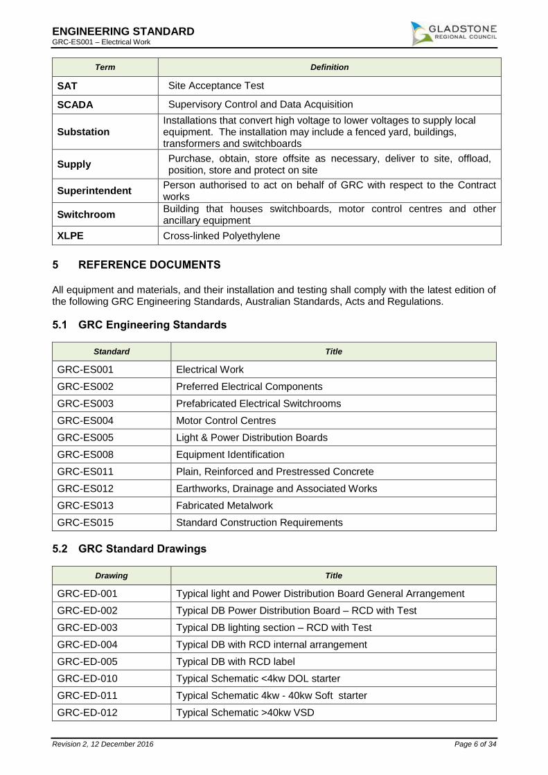
5.1 GRC Engineering Standards
Standard Title
GRC-ES001 Electrical Work
GRC-ES002 Preferred Electrical Components
GRC-ES003 Prefabricated Electrical Switchrooms
GRC-ES004 Motor Control Centres
GRC-ES005 Light & Power Distribution Boards
GRC-ES008 Equipment Identification
GRC-ES011 Plain, Reinforced and Prestressed Concrete
GRC-ES012 Earthworks, Drainage and Associated Works
GRC-ES013 Fabricated Metalwork
GRC-ES015 Standard Construction Requirements
5.2 GRC Standard Drawings
Drawing Title
GRC-ED-001 Typical light and Power Distribution Board General Arrangement
GRC-ED-002 Typical DB Power Distribution Board – RCD with Test
GRC-ED-003 Typical DB lighting section – RCD with Test
GRC-ED-004 Typical DB with RCD internal arrangement
GRC-ED-005 Typical DB with RCD label
GRC-ED-010 Typical Schematic <4kw DOL starter
GRC-ED-011 Typical Schematic 4kw - 40kw Soft starter
GRC-ED-012 Typical Schematic >40kw VSD

ENGINEERING STANDARD GRC-ES001 – Electrical Work
Revision 2, 12 December 2016 Page 7 of 34
Drawing Title
GRC-ED-013 Typical MCC DB,UPS, 24 VDC Power Supply single line diagram
GRC-ED-014 Typical Schematic MCC single line diagram
5.3 Australian Standards
Standard Title
AS 1111 ISO Metric Hexagon Bolts and Screws
AS/NZS 1680 Interior Lighting
AS/NZS 1768 Lightning Protection
AS/NZS 2053 Conduits and Fittings for Electrical Installations
AS 2067 Substations and High Voltage Installations Exceeding 1kV ac.
AS 2293 Emergency Escape Lighting and Exit Signs
AS/NZS 3000 Electrical Installations (Australian/New Zealand Wiring Rules)
AS/NZS 3008 Electrical Installations – Selection of Cables
AS 3011 Electrical Installations – Secondary Batteries Installed in Buildings
AS/NZS 3017 Electrical Installations – Verification Guidelines
AS/NZS 5000 Electric Cables
AS/NZS 61439 Low Voltage Switchgear and Controlgear Assemblies
NEMA VE-1 Metal Cable Tray Systems
5.4 Acts and Regulations
Title
Electricity Act 1994
Electricity Regulation 2006
Electrical Safety Act 2002
Electrical Safety Regulation 2002
Professional Engineers Act 2002
Professional Engineers Regulation 2003
Work Health and Safety Act 2001
Work Health and Safety Regulation 2011
ENGINEERING STANDARD GRC-ES001 – Electrical Work
Revision 2, 12 December 2016 Page 8 of 34
GENERAL REQUIREMENTS 6
6.1 Health, Safety and Environment
The Council has a commitment to attaining the highest standards in health, safety, environment and community obligations. The Contractor shall comply with GRC’s health, safety, environmental and community policies and procedures. a) The Contractor shall comply with GRC Safe Work Procedures for all work undertaken on
site. The Contractor shall submit a Work Method Statement (WMS) prior to commencing work.
b) No work shall be carried out on live equipment unless specifically authorised by the Superintendent.
c) The Contractor shall comply with GRC isolation procedures for all work undertaken on site.
d) The Contractor shall use Job Safety Analysis (JSA) and Take 5 techniques for risk assessment. All possible measures shall be taken to reduce risks to appropriate and safe levels prior to commencing work.
e) All incidents shall be reported to the Superintendent as soon as is practicable.
f) The Contractor shall comply with all obligations under the Work Health and Safety Act and Regulations.
g) The Contractor shall comply with all obligations under the Environmental Protection Act and Regulations. This includes storage and disposing of contractor construction waste, chemicals and empty containers in the approved manner.
6.2 Low Voltage Insulated Gloves
All electrical workers on GRC sites, including Contractor employees, shall wear approved low voltage insulated gloves with a current test certification when working on or near live low voltage supplies. Damaged gloves shall not be used. Typical work that will require gloves to be worn includes but is not limited to:
Fault-finding on live low voltage power and control circuits.
Testing low voltage circuits to confirm correct isolation.
Calibrating or fault finding on low voltage supplied items of equipment.
The Contractor shall supply all gloves used by Contractor employees.
6.3 Cables Coated with Asbestos Based Fire Retardant Material
Contractors shall ensure that the correct work procedures are followed when work is performed that involves the installation or removal of cables and there is the potential for the disturbance of asbestos-based fire retardant material.
6.4 Asbestos Based Material in Switchgear Panels
Some older switchgear panels on GRC sites have arc chute covers and/or internal heat protection panels made of material that contains asbestos. Panels containing this material are identified on the panel door with a warning label. Contractors shall follow GRC safe work procedures for work to be undertaken in these panels.

ENGINEERING STANDARD GRC-ES001 – Electrical Work
Revision 2, 12 December 2016 Page 9 of 34
6.5 Insulation Material Containing Chrysotile Asbestos Fibres
Some redundant control cabinets may have equipment-mounting boards fabricated from insulation material that contains chrysotile asbestos fibres. All control cabinets shall be inspected before disposal and any such boards shall be removed and disposed of at the Council's asbestos disposal site.
6.6 Capacitors Containing PCB’s
Redundant light fittings and control boxes may include capacitors that contain PCB’s. Unless it can be positively determined that the redundant capacitors do not contain PCB’s, they shall be removed from the fitting or box prior to their disposal at the Council's dumping area.
6.7 Prohibited Materials
Components that contain asbestos, mercury, cadmium, PCB’s, silica gel containing the indicating agent cobalt chloride or any other products either known to or suspected of having carcinogenic or other detrimental long or short term effects on the health of personnel if they are inhaled, ingested or otherwise contacted during normal and reasonable use shall not be used in electrical equipment or installations on GRC sites. All components supplied by Contractors as well as their own fabrication tools and equipment brought on site to carry out electrical installation work covered by this Engineering Standard shall comply with this requirement.
6.8 Site Inductions
The Contractor shall ensure that all Personnel working on Site must have obtained all relevant GRC inductions prior to work commencing.
6.9 Supervision
All work shall be supervised throughout by a competent person or persons experienced in the type of work being performed. Unless agreed otherwise by the Superintendent, the Supervisor shall: a) Be nominated prior to commencement of work and their name and contact details provided.
b) Be contactable at all times for the duration of installation and commissioning periods.
c) As far as practical be the same person(s) for the duration of the project.
d) Be at the worksite as often as is necessary to adequately carry out the tasks given below:
o Supervise tradesmen and liaise with the Contract Superintendent.
o Ensure all workmanship is to be of the highest standard throughout.
o Understand all aspects of the scope of work and ensure that work is completed according to scope.
o Be responsible for ensuring that work is carried out according to applicable regulations, standards, safe work practices and levels of workmanship.
o Ensure that work is carried out according to schedule and be familiar with schedule constraints.
o Keep the Contract Superintendent informed of progress and any issues needing resolution.
o Obtain authorisation in writing for any cost variations before work outside the scope is performed.
ENGINEERING STANDARD GRC-ES001 – Electrical Work
Revision 2, 12 December 2016 Page 10 of 34
o Obtain authorisation in writing for any departure from standards before any work is performed.
o Ensure that the work site is kept clean, tidy and safe.
6.10 Personal Protective Equipment (PPE)
a) The Contractor shall provide all PPE, unless stated otherwise to meet GRC Site Standards. As minimum, hard hats, safety glasses, steel-cap boots and high visibility clothing shall be worn at all times while on site.
b) It is the Contractor’s responsibility to ensure that all Sub-Contractors under their supervision are informed of the PPE requirements on site.
6.11 Quality of Workmanship
a) All work carried out shall be to a high standard of workmanship. Competent personnel experienced in their respective work shall complete all work in a neat, substantial and tradesman-like manner, in accordance with the current best practice.
e) Personnel carrying out any particular task shall be suitably qualified, trained and possess the necessary skills to complete the task to a high standard of workmanship.
f) All electrical works shall be performed by electrical tradesmen with a current Queensland Electrical License working under a person with an Electrical Contractor’s License, licensed under the Queensland Electrical Workers and Contractors Act.
g) The Contractor shall provide all quality assurance installation verification documents such as ITPs, test and check sheets signed by the Contractor’s Representative.
h) Building structures and surfaces that are disturbed in effecting the electrical installations shall be restored to their original condition.
i) The Company reserves the right to inspect all works and request re-work if the quality of work is not acceptable to the Company’s Representative. If the Company’s Representative is not satisfied that the personnel carrying out particular work possess the necessary skills, the Contractor shall provide alternative personnel.
6.12 Equipment and Materials
a) All materials and equipment shall be new, free of defects, of the best quality and of a design most suitable for operating under the conditions prevailing at the site. Materials and equipment shall operate without distortion, deterioration or subject to excessive stresses that might affect the performance or life of the equipment or materials.
j) Equipment selection and design shall be based on greater than 20 years’ reliable operational life.
k) Unless specified otherwise, all equipment used on the installation shall be selected in accordance with Engineering Standard GRC-ES002 – Preferred Electrical Components.
l) The Contractor shall take delivery of, load or unload as necessary, transport to the site, securely store and protect the equipment and materials.
m) The Contractor shall submit to the Superintendent for approval a list of the materials proposed to be supplied for the installation. The Contractor shall provide complete details, including catalogue information, for the proposed equipment for installation.
6.13 Painting and Surface Preparation
Steelwork surface preparation, anti-corrosion protection and the surface coating system shall be to Australian Standards. Evidence shall be provided that these items meet the relevant Australian Standards.

ENGINEERING STANDARD GRC-ES001 – Electrical Work
Revision 2, 12 December 2016 Page 11 of 34
The painting system used for local control stations and other field panels shall be powder coated to a total thickness of 70 microns. The standard painting system of the supplier may be used provided details of the system are submitted and approval for use is received from the Purchaser. a) The colour and finish of Local Control Stations and field panels shall be ‘Pale Eucalypt’
b) Escutcheon panels shall be 'Gloss White'
6.14 Equipment Identification and Labels
a) Each item of electrical and instrumentation equipment, including all internal and external components and accessories, shall be clearly identified by an engraved or etched label. Labels shall be marked with the identification number and name of the equipment.
b) All labelling shall be provided in accordance with Engineering Standard GRC-ES008 – Equipment Identification Labels.
c) For new installations, safety signage shall be fitted to comply with AS 3000 and for high voltage installations AS 2067.
6.15 Drawing Control
The Contractor shall not carry out any electrical installation work without approved drawings marked ‘For Construction’ and a Scope of Work document. All work shall be carried out in accordance with the approved design documentation. The Contractor shall be responsible for the control of all drawings once they have been issued for construction. The Contractor shall ensure that a paper copy of all drawings marked “MASTER” is available before construction starts. The master copy shall include all latest mark ups to show the “As Built” status of the equipment. This will also apply for the installation of equipment in a pre-fabricated building off-site. The Contractor shall be responsible for the provision of ‘As-Built’ installation drawing markups. This shall include the following:
Create a master set of drawings (each drawing must be stamped MASTER).
Make available the master set at all times in the switchroom for inspection by the Superintendent.
Update the “Master” drawings with red ink during installation, commissioning and testing to show the as built status of the equipment.
At the completion of the contract, the Contractor shall submit a complete set of the contract drawings to the Superintendent stamped “As-Built” and individually signed and dated by the Contractors Representative. This set of drawings shall reflect and contain all variations between the issued contract drawings and the actual installation marked-up in red ink. The Contractor shall provide all necessary QA documents to the Superintendent for approval, prior to energising the installation. The QA documents include inspection and test plans, test sheets and check sheets. These documents shall be approved and signed by the Contractor’s Representative.
6.16 Change Management
The Contractor shall bring to the attention of the Superintendent any errors or omissions that are detected in the design documentation.

ENGINEERING STANDARD GRC-ES001 – Electrical Work
Revision 2, 12 December 2016 Page 12 of 34
The Contractor shall check and confirm on site all cable lengths and distances prior to cable installation and advise the Superintendent if there are any discrepancies. The Contractor shall not vary from the approved design documentation without prior approval.
6.17 Interference
Contractors shall not interfere with the operation of or hinder access when working alongside an operating facility without prior written notice to and written approval from the Superintendent.
6.18 Operation of Council’s Equipment
Contractors shall not operate or attempt to operate any of the Council’s process equipment and facilities under any circumstances.
INSTALLATION OF ELECTRICAL EQUIPMENT 7
7.1 General
a) The location for the installation of equipment shall be determined from the contract drawings and in consultation with the Superintendent on site. All locations shall be selected and equipment oriented to provide access for maintenance. All locations shall be approved by the Superintendent prior to the equipment being installed.
b) Unless approved otherwise, all electrical equipment shall be arranged such that cabling is bottom entry.
c) Following the installation of equipment, protection shall be provided for that equipment against any damage that might occur due to the construction activities taking place.
d) The Contractor shall be responsible for the manufacture of minor support structures to suit particular requirements.
e) Any damage that occurs to equipment after installation shall be made good to the satisfaction of the Superintendent, or the equipment replaced.
f) If damage occurs to the protective coating of any equipment after installation, a temporary protective coating of zinc enriched paint or similar shall immediately be applied to prevent the development of corrosion prior to a full restoration of the protective coating.
g) At the completion of installation, the equipment shall be left clean, painted, tested, in good and serviceable order and all electrical test sheets shall be submitted to the Superintendent.
h) The centre of all control stations, instruments, meters, light switches and power outlets shall be 1300mm above the operating floor or platform level. All field equipment shall be mounted so that cabling is bottom entry, unless stated otherwise.
i) Final locations of all equipment, including cable ladder and conduit routes, shall be verified by the Superintendent prior to commencement of equipment installation.
7.2 Electric Motor Driven Equipment
Installation of motor driven equipment and the alignment of motors will generally be carried out by others.
7.3 GRC Owned Power Transformers
a) Transformers shall be installed in accordance with the project drawings and manufacturer’s instructions.

ENGINEERING STANDARD GRC-ES001 – Electrical Work
Revision 2, 12 December 2016 Page 13 of 34
b) Transformers shall be mounted on a properly engineered and designed concrete plinth and levelled using shims prior to bolting down.
c) Cables to the transformer shall be installed in underground conduits or in accordance with the project drawings and terminated in accordance with this Engineering Standard. The Contractor shall check phasing before final cable connections are made.
d) Auxiliary equipment that has been removed for transport shall be fitted in accordance with the manufacturer’s instructions.
e) The earthing to the transformer and in the transformer compound shall be installed in accordance with the project drawings.
f) The Contractor shall ensure that the transformer oil tapping connection is readily accessible for maintenance personnel to take oil samples.
7.4 Motor Control Centres
a) Motor Control Centres shall be designed and manufactured in accordance with the requirements of Engineering Standard GRC-ES004 – Motor Control Centres.
b) Motor Control Centres (MCC) shall be erected and assembled strictly in accordance with the contract drawings and with the manufacturer’s installation instructions.
c) The Contractor shall ensure that there are appropriate clearances between opened panel doors from the MCC, other equipment and switchroom walls.
d) The motor control centre may be shipped in sections which will require joining of the sections and the busbars. Each shipping section shall be provided with lifting lugs. The Contractor shall use the switchboard lifting lugs for lifting and handling so that no distortion will result from lifting. The Contractor shall use rollers to move the MCC sections and take care not to damage the switchroom floor, walls and other equipment. The MCC shall be firmly bolted to the switchroom foundation steelwork or secured by appropriately sized masonry bolts to a concrete floor. The MCC sectioned busbar joints shall be bolted with a torque wrench using torque settings supplied by the MCC manufacturer.
e) Cable entries shall be bottom entry. If top cable entry is required, the Contractor shall obtain approval from the Superintendent. Cable entry gland plates shall be 6mm thick brass or aluminium plate and solidly bonded to the MCC earth bar with an earth conductor of minimum size 25mm².
7.5 Distribution Boards
a) Distribution boards shall be designed and manufactured in accordance with the requirements of Engineering Standard GRC-ES005 – Light and Power Distribution Boards.
b) Field distribution boards shall be mounted on brackets fixed to steel work, or on a suitable stand. Outdoor distribution boards shall be provided with a protective sun shield and overhanging rain hood.
c) The top of the distribution boards should be 2000mm above the operating floor or platform level.
d) Power and lighting circuits shall have earth leakage protection set at 30mA for both single and three phase circuits.
e) If required, distribution boards shall be fitted with daylight control circuits and emergency lighting test circuits.
f) When a sub-circuit is connected into a distribution board, the cable cores shall be identified with PVC slip-on markers with black characters on a white background. An active wire shall be numbered with the same number as the circuit breaker to which it is connected, e.g. CB5-A. The neutral wire shall be numbered with the same number as the circuit breaker to which its active conductor is connected, e.g. CB5-N, and shall be connected into the corresponding

ENGINEERING STANDARD GRC-ES001 – Electrical Work
Revision 2, 12 December 2016 Page 14 of 34
neutral bar hole, e.g. hole number five. The earth wire shall be numbered with the same number as the circuit breaker to which its active conductor is connected, e.g. CB5-E, and shall be connected into the corresponding earth bar hole, e.g. hole number five.
g) As-built circuit schedules shall be installed in clear plastic sleeves mounted on the inside of each distribution board’s door.
7.6 PLC, HMI, Control and Communications Panels
a) PLC, Control and Communications Panels shall be installed in accordance with the project layout drawings, in nominated locations with sufficient space for accessing inside the panels with opened doors.
b) The panels may be installed on a plinth subject to the project requirements.
c) The centre of HMI screens shall be 1500mm above floor level.
d) Instrument and control cables shall be terminated to the terminals specified on the project drawings. Stripped cores of the cables shall be contained neatly in cabinet ducting with sufficient excess length.
7.7 UPS, Battery Chargers and Batteries
a) UPS and Battery Chargers shall be installed in accordance with the project drawings and supplier recommendations. A UPS bypass switch shall be installed in a nominated location in the vicinity of the UPS and shall be easily accessible for operation.
b) Batteries shall be installed in a battery cabinet strictly in accordance with the manufacturer’s instructions. Battery installations in buildings shall comply with AS 3011.
c) Adequate venting shall be provided for batteries installed inside cabinets as per supplier’s recommendations.
7.8 Motor Local Control and Isolator Stations
a) Local Control Stations (LCS) shall be designed and constructed in accordance with the approved drawings and shall incorporate the following features as a minimum:
o Enclosure fabricated from 1.6mm 316 grade stainless steel with a minimum IP65 protection rating. Enclosure shall incorporate a 316 grade stainless steel rain hood.
o Minimum enclosure dimensions of 400mm height, 300mm width, 200mm depth.
o Three phase motor isolator with auxiliary contact, interlocked with enclosure door so that enclosure can only be opened with the isolator in the OFF position.
o Emergency stop pushbutton.
o Din rail terminal block for termination of control cables in accordance with the approved drawings.
o Earth terminal bar.
o 5mm thick brass gland plate.
b) Where specified by the approved drawings or documentation, manual stop/start pushbuttons and a control selector switch, along with any required control terminals and internal wiring, shall also be included in the LCS.
c) Each isolator shall be fitted with an auxiliary N/O contact to enable isolated status indication and interlocking with the starter contactor.
d) The line terminals of each isolator shall be shrouded to prevent accidental contact.

ENGINEERING STANDARD GRC-ES001 – Electrical Work
Revision 2, 12 December 2016 Page 15 of 34
e) The emergency stop pushbutton shall have a red mushroom head operator that will latch in the OFF position. Manual stop and start pushbuttons shall be red and green respectively.
f) Control selector switches shall be three position switches and shall be labelled LOCAL-OFF-REMOTE unless specified otherwise.
g) Each local control station shall be located adjacent to, or within six metres (process permitting) of the motor being controlled and in a position that provides a clear view of the motor.
h) Local control stations shall be located such that an operator is not exposed to process substances or other operating hazards.
i) Local control stations shall not be located where they are exposed to damage from maintenance activities or passing traffic.
j) Each local control station shall be installed on a mounting frame and stand. The LCS for groups of drives may be located on a common stand in a central location.
7.9 Field Junction Boxes and Panels
a) Field junction boxes and panels shall be selected in accordance with the requirements of Engineering Standard GRC-ES002 – Preferred Electrical Components.
b) Field junction boxes and panels shall be fabricated from 316 grade stainless steel with a minimum IP65 protection rating.
c) Field junction boxes and panels shall be mounted on brackets fixed to steel work or on a suitable stand, and if exposed to the weather shall be fitted with overhanging rain guards. Where exposed to sunlight a sun shade shall be fitted.
d) Field junction boxes and panels shall be fitted with a hinged door secured with a locking mechanism. Cables shall be terminated on gland plates of brass or aluminium, of minimum thickness 5mm.
7.10 Lighting
a) Notwithstanding the location shown on the drawings, the Contractor shall ensure that each light is located in a position that provides safe access for maintenance. Preference shall be given to locating light fittings where they can be reached from an existing platform or walkway.
b) The Contractor shall bring to the Superintendent’s attention prior to installing the fittings, any lighting locations as shown on the drawings that will not allow safe access for maintenance, or are not appropriate in that location. Light fittings shall be installed complete with lamps, lenses, reflectors, guards and covers.
c) The Contractor shall ensure that light fittings installed in rows are positioned in a straight line and at the same height.
d) Light fittings shall be securely screwed or bolted directly to building structures, or to brackets that are bolted to mounting poles or welded to the structure. All mounting poles shall be fitted with a facility to lower the pole for maintenance. The poles shall be located and oriented to allow unimpeded lowering and safe and convenient access to the light fitting when in the lowered position.
e) Control gear shall be installed within 12m of the light fitting and in locations easily and safely accessible without the use of ladders.
f) Indoor office light fittings shall be fitted with flexible cables and plug tops. A matching outlet shall be installed adjacent to the fitting and connected to the permanent wiring.
g) Where required, junction boxes shall be installed at light fittings to permit the looping of wiring from fitting to fitting. These junction boxes shall be installed in easily accessible locations and shall be an approved three way weather proof type.

ENGINEERING STANDARD GRC-ES001 – Electrical Work
Revision 2, 12 December 2016 Page 16 of 34
h) High bay lighting shall be suspended from a galvanized steel bracket by two galvanized shackles. Two stainless steel safety chains shall be installed, attached to the light fitting body at one end and the building at the other by threaded nuts and bolts with flat and spring washers. High bay light fittings shall be fitted with a 2.5mm² flexible cables and plug tops. A matching outlet shall be installed adjacent to the fitting and connected to the permanent wiring.
i) Floodlight fittings shall be provided with an aiming angle indicator and after installation shall be aimed at the angle shown on the drawings.
j) The exterior lighting shall be controlled by a daylight switch. The daylight switch shall be installed in the nominated outdoor location. A bypass control switch, marked BYPASS-AUTOMATIC-OFF, shall be installed in the distribution board with the lighting control contactors.
k) Emergency light fittings shall be located in corridors, walkways, and stairs and above exit doors in accordance with AS2293. They shall be connected to the local lighting circuit and arranged to switch on when the local lighting fails, but not when local lighting is switched off.
l) An inspection of the lighting shall be undertaken during the hours of darkness to verify light levels, glare and the aiming of light fittings. Illuminance readings shall be taken at regular intervals and marked on lighting layout drawings and submitted with the as-built drawings.
7.11 Socket Outlets
a) Socket outlets shall be installed at the locations indicated on the contract drawings and on building columns. If no columns are available, the Contractor shall install a stand for the outlets.
b) All socket outlets shall be supplied from a circuit breaker with 30mA earth leakage protection.
c) All socket outlets installed in offices or in control room areas shall be moulded plastic, flush mounting and coloured white.
d) All socket outlets installed in outdoor and plant areas shall be Clipsal 56 HD IP56 series.
e) Welding outlets shall be placed so that any location where welding is likely to be required will be within 30m from the outlet. Welding outlets shall be 415V, three phase + neutral, 50A, 5 pin outlets, unless otherwise stated. The 3-phase outlets for welding equipment and other portable tools shall be protected by appropriate Residual Current Devices (RCD) with 30mA sensitivity.
7.12 Lightning Protection
a) Lightning protection shall be installed on structures as required by the project drawings and requirements of AS/NZS 1768 - Lightning Protection.
b) The lightning protection system shall include air terminals, down conductors, earth electrodes and an earthing system. All equipment shall be approved for the purpose of lightning protection.

ENGINEERING STANDARD GRC-ES001 – Electrical Work
Revision 2, 12 December 2016 Page 17 of 34
INSTALLATION OF INSTRUMENTS 8
8.1 Storage and Handling
Upon receipt, all instruments and ancillary equipment shall be kept in a dust and weatherproof store. When instruments are taken from the store for testing, they shall be returned to the store and repacked. All instruments shall be transported and handled with the utmost care. All covers and plugs on instrument connections shall be left in place until the proper connections are made. Machined surfaces such as flange facings shall be protected by covers until they are installed.
8.2 Calibration and Testing
a) The Contractor shall determine the requirements for calibration and testing of the various instruments according to the manufacturer's recommendations and in consultation with the Superintendent. Calibration and function testing shall be carried out on the instruments for which it is required and the results recorded. Where possible, the testing or calibration shall be performed in the Contractor's site workshop prior to installation of the equipment on site.
b) All test equipment used shall be calibrated to a NATA traceable standard, which has been calibrated within six months of the date of the tests to be performed and shall have accuracy equal to or exceeding that of the manufacturer's stated accuracy of the equipment under test. The Contractor shall submit copies of the calibration certificates to the Company’s Representative prior to carrying out any calibrations.
c) The personnel performing the calibrations must be fully conversant with both the equipment to be tested and the test equipment to be used.
8.3 Programming and Configuration
Unless directed otherwise, the Contractor shall enter all parameters, settings and configuration data required by any programmable instruments. This data will be the basic data for the application. Fine tuning of the configuration will be carried out by GRC. Program and configuration details and data sheets shall be provided to the Superintendent in electronic format.
8.4 Layout, Location and Arrangement
a) The Contractor shall ascertain on site, in consultation with the Superintendent, the exact location of all equipment to be installed including the location of instruments, instrument stands and brackets, instrument air reticulation, signal and impulse tubing, and the routing of cable ladders, conduits and cables.
b) Unless directed by the Superintendent, all field equipment shall be arranged so that cabling is bottom entry. The Contractor shall inform the Superintendent accordingly, and modify at his own expense, any top or side entry equipment.
c) Equipment shall have adequate clearance from other services and, when mounted along or in access ways, shall be positioned, modified or protected such that it does not present a hazard to vehicular or pedestrian traffic using the access way, nor be subject to accidental operation or damage. Access for the removal and replacement of in-line measurement and control devices must be considered when the mounting position of devices is being determined.
d) Instrument stands shall be mounted on concrete slabs, opposed to welding or securing to building columns, concrete structures or tanks.
e) Equipment and/or accessories shall not be mounted on building cladding or top handrails. Where equipment is mounted in close proximity to handrails, the supporting stands or bracketing shall be spaced to leave the handrails at least 75mm clear of obstruction.
ENGINEERING STANDARD GRC-ES001 – Electrical Work
Revision 2, 12 December 2016 Page 18 of 34
8.5 Work Normally Excluded
The Electrical/Instrumentation Contractor's scope of work will not normally include the installation of in-line instruments. The Mechanical/Piping Contractor shall be responsible for the installation of all in-line devices and equipment requiring mechanical installation works. These shall include but not be limited to:
Control Valves.
In-line Solenoid Valves.
Orifice Plates, Tapping Points and Flanges.
Magnetic Flowmeters.
Thermowells.
Instrument Air Supply headers including the primary isolation valves for each consumer.
Process connections on pipe work. The Contractor shall be responsible for liaising with the Mechanical/Piping Contractor during the installation of the above equipment, and shall provide the Mechanical/Piping Contractor with any instrument manufacturer's specific installation details or tolerances that may affect the instrument's performance.
8.6 Mounting
a) All instruments shall be mounted in accordance with the applicable instrument installation detail or manufacturer’s recommendation.
b) All instruments other than types specifically designed for vessel or pipe mounting shall be mounted on stands or within a panel.
c) All equipment shall be mounted so that it is accessible from the ground or platform without the use of ladders or scaffolding, unless otherwise approved by the Superintendent.
8.7 Instrument Labelling
The Contractor shall supply, engrave and fix in position nameplates and labels for the following items of equipment.
Instrument tag numbers if not supplied with the instrument.
Junction Boxes.
Cables.
Earth Terminal Bars. Nameplates and labels shall be stainless steel, unless otherwise approved. Refer to GRC Engineering Standard ES008 - Labelling, for specific details.
ENGINEERING STANDARD GRC-ES001 – Electrical Work
Revision 2, 12 December 2016 Page 19 of 34
INSTALLATION OF CABLES 9
9.1 General
a) All cables shall be as specified on the approved cable schedule. The Contractor shall obtain approval from the Superintendent for any departure from the specified cable types.
Cable lengths shown on the cable schedule are approximate and it is the responsibility of the Contractor to verify all lengths. The Contractor shall advise the Superintendent if any cable lengths in the cable schedule are short.
The Council will not except any claims based on lengths stated in the cable schedule.
b) The Contractor shall ensure by calculation, that cable sizes for unscheduled cables are rated correctly for current carrying capacity, voltage drop, fault withstand capacity, earth fault-loop impedance and other requirements in accordance with AS/NZS 3000 and AS/NZS 3008.
c) Low voltage power cables shall be multicore copper conductor with an integral insulated earth core, V90 insulated, 0.6/1kV grade PVC/PVC or XLPE/PVC orange circular cables to AS/NZS 5000.
d) Single core (SDI) V90 insulated, 0.6/1kV grade PVC/PVC or XLPE/PVC orange circular cables to AS/NZS 5000 may also be used where indicated on the cable schedule.
e) Earth cables shall be single core, stranded copper cables with 0.6/1kV Green/Yellow PVC single sheath insulation.
f) Variable speed drive motor power cables shall be 3 core + 3 earth EMC screened, 0.6/1kV grade XLPE/PVC to AS/NZS 5000.
g) High voltage power cables shall be 3 core XLPE insulated, screened and PVC sheathed with a voltage rating of 3.8/6.6kV, 6.35/11kV or 12.7/22kV to suit the application requirements.
h) Control cables shall be 0.6/1kV PVC/PVC with white cores and black core identification numbers, integral insulated earth core and black overall sheathing.
i) Instrument cables shall be PVC insulated PVC sheathed twisted pairs with individual and overall screen.
j) All cable types shall have metre markings stamped on the outer cable sheath.
9.2 Segregation of Cables
a) With the exception of fibre optic cables, no cables other than HV cables shall be installed in HV cable ladders or conduits.
b) Control, instrumentation or communications cables shall not be installed in the same conduit or duct as HV or LV cables.
c) Screened signal cables shall not be installed within 300mm of high or low voltage power and control cables.
d) Where ELV or signal cables run on the same ladder as low voltage power and control cables, a dividing barrier shall be installed on the ladder for the full length and a minimum spacing of 300mm maintained between the cables.
e) Network data and voice communications cables shall not be installed in the same cable ladder or conduit as HV, LV or ELV cables. They shall be installed in their own dedicated cable ladder or conduit.
9.3 Fibre Optic Cables
a. Fibre optic cables may be installed in any cable ladder with a preference for installation in HV cable ladders.
ENGINEERING STANDARD GRC-ES001 – Electrical Work
Revision 2, 12 December 2016 Page 20 of 34
b) When fibre optic cables are not installed in cable ladder they shall be installed in individual steel conduit or galvanised conduit for mechanical protection, with similar requirements to those applicable to power cables.
c) When the destination of a fibre optic cable is the same as that of a power or control cable, they may be installed in the same conduit provided there is sufficient capacity for both cables.
9.4 Top Entry Cables
a. Where cables enter a conduit or duct from above, provision shall be made to prevent the entry of water or other liquids by filling around the cables with a water-based silicone sealant and sheathing overall with a black heat shrink sleeve. Solvent-based sealants shall not be used.
b) Drainage openings shall be provided at the lowest point of the conduits nearest to the point of entry. Flexible conduits shall be drilled with a 6mm minimum diameter hole at their lowest point for drainage.
9.5 Bottom Entry Cables
Cable entries into all field mounted equipment shall be bottom entry as a first the first preference, followed by side entry where practical, to minimise the potential ingress of substances.
9.6 Protection of Installed Cables
a. Regardless of the method on installation, the Contractor shall ensure that all cables are fully protected from the risk of damage including mechanical impact, vibration, heat, chemical attach and termites.
b. The Contractor shall select cable routes to minimise risk of damage and install conduits, brackets, covers, barriers, vibration damping and whatever means are required to protect cables from the likelihood of damage.
b) All cables installed externally to a switchboard or electrical panel shall be installed in either cable ladder or conduit for the full length of the cable in accordance with the requirements of Sections 11 and 12 below.
c) Any cables leaving a cable ladder or conduit for connection to a final device shall be protected using heavy duty PVC sheath non-metallic flexible conduit and compatible nickel plated brass or stainless steel fittings and glands.
9.7 Sealing of Cable Penetrations
a. Any penetrations created for cable entry shall be sealed after completion of cable laying. Unused holes and conduits shall also be sealed. The sealing method used shall restore the integrity and degree of weatherproofing of the original surface.
b) A non-combustible foam sealant may be used to create a non-fire rated seal. Any excess foam shall be removed to leave a neat finish. Penetrations through fire rated walls shall be sealed in such a way that the original fire rating is restored. An approved fire rated mortar such as KBS Mortar shall be used. The section of cables inside the area to be sealed shall be carefully cleaned and the mortar installed in accordance with the manufacturer’s instructions.
9.8 Marking of Cables
a. All cables shall be identified with an approved cable marker and in accordance with Engineering Standard GRC-ES008 – Equipment Identification. The marker shall be engraved with the cable number as shown on the cable schedule. Cable markers shall be laser etched stainless steel tags attached to the cable with a minimum of two cable ties.

ENGINEERING STANDARD GRC-ES001 – Electrical Work
Revision 2, 12 December 2016 Page 21 of 34
b) Cable markers shall be attached at each end of the cable as a minimum. The location of the cable marker shall be selected to allow ease of reading as follows:
o Prior to the cable entering an enclosure for field mounted enclosures and MCC entries.
o Both sides of the gland plate for bottom entry enclosures where both sides of the gland plate cannot be viewed from the one location e.g. bottom entry MCC’s and switchboards inside a substation.
o Single core power cables shall have 150mm of coloured heat shrink applied at the termination point of the cable. The colour of the heat shrink shall indicate the phase of the cable e.g. red, white or blue.
TERMINATION OF CABLES 10
10.1 General
a. All cable cores shall be terminated including earths and shields with the exception of spare control cable cores. Each core shall be fitted with the correct type of lug or pin and crimped, except when insulation displacement terminals are used. Each core shall be identified, either with a ferrule number or by colour.
b) Cables not installed in conduit shall be fitted with the correct compression gland. Instrument cable shielding shall be earthed in accordance with the drawings and generally at the source end.
c) The cable shall be arranged, clamped or otherwise supported so that the termination is not supporting the weight of the cable.
d) HV cable terminations shall be carried out by suitably qualified personnel experienced in HV cable terminations.
10.2 Termination of Low Voltage Power Cables
a. The cores of LV power cables shall be terminated with the correct size crimp lug. The exposed conductors shall be completely enclosed within the barrel of the lug prior to crimping. Lugs shall be crimped with a crimping device which, if hand operated, shall be of a type that will not release until the correct crimping pressure has been reached. All conductors with a cross-sectional area less than 6mm2 shall be terminated by means of insulated crimp (bootlace ferrule) or compression lugs unless otherwise specified. Preferably, only one wire shall be crimped in each lug or pin.
b) Uninsulated lugs shall be insulated by applying phase coloured heat shrinkable sleeving over the barrel of the lug and equal distance along the conductor sheath.
c) Electrostatic screening present on VSD power cables shall be earthed at both ends of the cable over the largest surface area possible. Earthing at motors shall be achieved using a gland designed for this purpose (EMC), and earthing at the VSD cubicle shall be achieved by clamping the screen to an earthed bar.
d) All armouring for cables carrying low voltage and higher shall, when entering non-metallic boxes, be earthed through the cable gland to an earthed stud inside the box.
10.3 Termination of Control and Instrumentation Cables
a. External sheathing shall be stripped back to within 50mm of the point where the cable enters the termination enclosure. Sufficient length of cable shall always be left to permit re-termination, and the preferred arrangement is for cables cores to be cut such that each core can reach the most distant terminal in the relevant terminal strip. Wiring not contained within a duct shall be neatly loomed and tied with PVC cable ties.
ENGINEERING STANDARD GRC-ES001 – Electrical Work
Revision 2, 12 December 2016 Page 22 of 34
b) All cores of control and instrument cables shall be terminated at both ends of the cable with the exception of spare cores. Each spare core shall be fitted with a ferrule marked SPARE, boot-laced and terminated. If terminals for termination of spare cores are not available, the bare spare core ends shall be cut off flush with core insulation, terminated to a blue point connector and left in the duct.
c) For screw type terminals, correct sized crimp lugs or ferrules shall be crimped to the conductor and screen drain wire with a crimping tool of a type that will not release until the correct crimping pressure has been reached. The drain wire shall be sleeved with a clear sleeve prior to crimping. The crimp lug or ferrule shall be inserted into the terminal and the screw tightened to the correct torque.
d) For insulation displacement type terminals, the wire shall be inserted into the terminal using the correct tool and technique. Drain wires shall be sleeved with clear sleeving prior to termination.
e) Screen drain wires for instrument cables shall be terminated to an earthed terminal at the switchroom end. In marshalling boxes, screens shall be cut off at the end of the cable bedding, and drain wires shall be fitted with clear PVC insulating tubing. The exposed screen at the end of the bedding shall be insulated with black heat shrink tubing. Drain wires shall be connected at dedicated terminals to ensure continuity of the screen shielding system.
f) At field equipment, the screens and drain wire shall be cut off at the end of the cable bedding, and the exposed screen at the end of the bedding shall be insulated with black heat shrink tubing.
g) The requirements for earthing of protective screens may vary from situation to situation and care shall be taken to comply with the drawings in each case.
10.4 Ferruling of Control and Instrument Cable Cores
All control, instrumentation and communications cables shall have numbered ferrules fitted to each core and to the screen drain wire. Numbers shall be in accordance with the contract drawings. Ferrules shall have black characters engraved on a white strip and fitted into a transparent carrier. The carrier shall be a type that encircles the core and shall be sized such that it will not slip off over the lug or pin.
10.5 Termination of Communications Cables
a. The termination of communication cables shall be carried out correctly and in accordance with any specific requirements applicable. Communications cables terminated at terminals shall be terminated generally as above with the exception of removal of the outside sheath. The length of cable stripped out of the outside sheath and protective shield for termination shall be kept to a minimum and the twisting of the pairs shall continue up to the terminals.
b) Where there is a requirement to fit a plug or terminating device to a communications cable, this shall be done correctly, in accordance with the relevant instructions and by personnel skilled in such tasks. Care shall be taken to earth the shield or screen in accordance with the relevant instructions. General practice shall be to make the screen continuous along the communications link and earthed at one end only.
10.6 Jointing of Cables
a. All new cables shall be installed as continuous lengths with no joints other than when it is not possible or practicable to obtain sufficient length from the manufacturer for a single run.
b) Cable joints may also be accepted when existing cables are extended to accommodate relocation of equipment. When joints are required, they shall be approved by the Superintendent. The location of the joint shall be chosen to provide good access for later inspection and repair, and shall be marked on the drawings.

ENGINEERING STANDARD GRC-ES001 – Electrical Work
Revision 2, 12 December 2016 Page 23 of 34
c) Joints in power cables shall be a resin encapsulated type and shall generally be located in the cable ladder. Joints in control, instrumentation and communications cables shall be made at labelled terminal blocks in junction boxes and shall be mounted on columns or similar to provide good access from either ground level or a platform.
d) Joints in all underground cables shall be a resin encapsulated type, shall be made in a cable pit and covered by a concrete cover marked “Cable Joint Below”.
10.7 Cable Glands and Shrouds
a. Cable sealing glands shall be used to terminate all cables except those terminated using flexible conduits and fittings. Glands shall be 316 grade stainless steel or nickel-plated brass UFP types unless specified otherwise.
b) Stainless steel cable glands shall be used to terminate all HV cables.
c) Aluminium cable glands shall not be used for any application on site.
d) PVC shrouds shall be used on all glands on site, to reduce the possibility of ingress of moisture past the gland.
e) 11kV and 3.3kV cable glands regardless of their connection being top or bottom entry into an enclosure, shall have UV stabilised heat shrink applied to the glands.
f) PVC glands may be used in switchrooms and control rooms only unless specified otherwise.
10.8 Redundant Cables
10.8.1 Removal
Redundant cables shall be completely removed unless otherwise specified. The following procedure shall generally be followed for all cable removal: a. Isolate cable source of supply following standard isolation procedures and confirm cable is
dead by testing at both ends of the cable.
b) Disconnect both ends of the cable.
c) Verify further that the correct cable has been isolated by shorting two cores at one end and testing the other end with an ohmmeter.
d) Proceed to remove the identified cable and cut the cable off in short sections after removal where the loose end of the cable is within the field of vision of the person cutting the cable. The cut-off point shall be reached by ‘hand over hand’ identification of the cable from the loose end.
Following the removal of all redundant cables from a location, all holes in switchboards, MCC’s, terminal boxes and the like shall be plugged, sealed, or, in the case of the removal of a large number of cables from a location, a new blank gland plate shall be provided. The method adopted shall not compromise the IP rating of the enclosure or lessen the electrical integrity of the equipment. When cables have been removed from building penetrations and fire rated or weatherproofing sealant has been disturbed, removed or holes are left in it by cable removal the Contractor shall restore the integrity of the sealant using Council approved sealant suitable for the location after all redundant cables have been removed.
10.8.2 Removal of Large Numbers of Redundant Cables
Where a project such as the replacement of an MCC requires the removal of a large number of redundant cables Contractors may delay removal of individual cables until all cables to be removed

ENGINEERING STANDARD GRC-ES001 – Electrical Work
Revision 2, 12 December 2016 Page 24 of 34
as a part of the project have been isolated and identified and/or the new installation has been commissioned. All redundant cables may then be removed at the same time. Individual cables awaiting removal shall be identified and bonded as per Section 10.8.4 below and temporarily stored in a manner that does not interfere with other activities in the area. The above requirement to bond, tape and identify a cable that will be completely removed the same day it is disconnected need not be carried out. However, any cable that is only partially removed at the end of the working day shall be identified, bonded, taped and then safely stored ready for removal the next day.
10.8.3 Redundant Cables Impractical to Remove
Cables that Contractors consider impractical to remove shall be brought to the attention of the Council. Reasons that may qualify a cable for not being removed shall include but not be limited to: a. Cable is of considerable length and installed at the bottom of a heavily loaded cable ladder
where it is physically impossible to access and remove the cable.
b) Where a safety-risk-analysis has identified a significant risk to personnel if a complete removal was undertaken.
c) Cables are installed underground in concrete slabs. This applies particularly to single cables between a motor and an adjacent column where the cable is to be abandoned and it is impossible to remove the cable due to a collapsed or blocked underground conduit.
Contractors shall not automatically assume that an application to not remove a cable will be successful as the Council may have special reasons for removing a cable.
10.8.4 Redundant Cables not to be Removed
When the Council agrees it is not practical to remove redundant cables, one of the following procedures shall be used to safely secure the cable. The procedure used shall depend upon the accessibility of both ends of the cable. a) If both ends of the cable are accessible and the cable can be disconnected from its’ source
of supply then both ends shall be securely bonded, the cable ends shall be taped and the cable shall be stored within the confines of the cable tray.
The term 'bonded' in this instance shall be taken to mean establishing a sound common electrical connection between all cores including the earth core. Lugging all cores and bolting all of them together shall achieve this. An alternative approved method of bonding that does not require the lugging of all cores is to connect all cores using a single brass split bolt connector. The use of hose clips, nylon zip ties or similar to achieve bonding is not permitted.
Cable markers similar to those used for cable numbering shall be attached at both ends of the cable stating ‘REDUNDANT CABLE EX XXXXXXX’ where XXXXXXX is the number that was applied to the cable when it was in use.
b) If one end of a cable to be removed is terminated in a location that contains live equipment that needs to be totally isolated to safely remove the cable but cannot be isolated without major disruption, the following procedure shall be followed:
i. Isolate the source of supply of the cable to be removed and lock out and tag in the approved manner.
ii. Identify the redundant cable where it exits the electrical enclosure and confirm that the cable is no longer live.
iii. Cut the cable just outside where it exits the enclosure leaving enough length to terminate the cable still connected to the enclosure in a phenolic or similar j-box.

ENGINEERING STANDARD GRC-ES001 – Electrical Work
Revision 2, 12 December 2016 Page 25 of 34
Leave these cores not bonded but open circuited and either individually tape or connect to terminals in the box. Fill in an information tag and leave in the box. The reasons for not bonding cores in this application are to avoid creating an illegal MEN link between the earth wire and any neutral wire in the cable or, should the still connected wires be accidentally activated, the following fault could damage equipment and compromise personal safety.
iv. Fill in an information tag and hang on the cable where it terminates inside the enclosure. If the cable cannot remain terminated, disconnect and tape individual cores and then completely over tape all cores.
v. Advise the Superintendent who will maintain a register of cables that have been made redundant in this manner for later removal by others from the switchboard or electrical enclosure when equipment comes off line.
vi. Completely remove the cut off external cable.
vii. If an external redundant cable has been approved by the Council to remain in position bond and tape the other end of the cable just cut off and terminate and stow in the trays above the electrical enclosure as described above.
viii. Identify, bond and tape the field end of the cable just cut off and terminate and stow in the ladders as described above.
In both of the above applications, if cable ladder is not available to stow the cables, the cables shall be terminated into a phenolic or similar junction box fixed to the structure and bonded, over taped and stored inside the box.
INSTALLATION OF CABLE LADDER 11
Cable ladder systems shall be installed to provide continuous mechanical and UV protection and support whenever large numbers of cables are to be installed between locations and between locations and individual or grouped items of equipment. All cable ladder, connectors and covers of a single ladder system shall be constructed of the same material. These components and their fittings and accessories shall be designed and constructed by the same manufacturer and shall be in accordance with NEMA Standard VE1 as a minimum requirement.
11.1 Routing of Cable Ladder
Cable ladder routing shall be as indicated in the contract drawings. In the event that the Contractor is required to determine a cable ladder route, the route chosen shall avoid areas of frequent maintenance activity such as above pumps or mechanical equipment, or under tanks. Where possible, the routes chosen shall also avoid areas where cranes may need to swing when dismantling piping, valves or other frequently dismantled equipment. The route shall strive to provide safe access for personnel required to install cables or access the ladder and shall be approved by the Superintendent prior to installation of cable ladder.
11.2 Cable Ladder Types and Materials
a) Cable ladders shall be manufactured of materials to suit the environment where they are to be installed. Each cable ladder shall have a minimum of 20% spare capacity.
b) NEMA 20A and NEMA 20C aluminium ladders shall be used in all areas including conveyor systems, process areas, switchrooms, substations, workshops and termination rooms. NEMA 20A aluminium ladder is classified as standard duty and NEMA 20C aluminium ladder is classified as heavy duty as outlined below.
ENGINEERING STANDARD GRC-ES001 – Electrical Work
Revision 2, 12 December 2016 Page 26 of 34
c) Heavy duty ladder shall be used for all external cable ladder installations unless specified otherwise.
d) Standard duty cable ladder shall only be installed inside substations, switchrooms and control buildings.
e) Standard duty cable ladder may also be used in external application for short runs up to 1m, to protect cables prior to entry to Local Control Stations.
f) 316 grade stainless steel ladder, covers and support brackets shall be used where the cable ladder may be occasionally or frequently subjected to corrosive spray or splashing, or installed within 5m of open plant containing process fluids.
g) Hot-dipped galvanised admiralty pattern type cable tray is only permitted inside equipment such as switchboards, MCC’s and control panels.
h) Cable ladders manufactured from fibreglass, plastics or of wire rack construction are not permitted on GRC sites.
11.3 Cable Ladder Dimensions
a. Ladders shall be 6 metres in length except for stainless steel ladder that shall be supplied in 3 metre lengths.
b) All ladders shall have inside widths of 150, 300, 450 or 600mm as specified in the drawings. The use of wider trays is discouraged due to space limitations but may be proposed for special applications subject to the approval of the Superintendent.
c) Standard rung spacing for all types shall be 300mm.
d) The radius of change of direction ladder fittings such as bends, tees, crosses and risers shall be 450, 600 or 900mm depending on the application.
e) The use of hinged horizontal and vertical splice plates is permitted provided their use allows the correct cable bending radii to be obtained.
11.4 Cable Ladder Supports
a) Cable ladder shall be supported on pipe rack or on purpose made supports that may either be free standing or fixed to existing structures. The location of the supports shall be in accordance with the requirements of the NEMA Standard VE-1. The maximum separation for supports shall be six meters. At any change of direction of the ladder, a support shall be provided within 750mm of the direction change and on all sides of the direction change.
b) Vertical ladder runs shall be supported with a maximum spacing of 2.5 meters between supports.
c) Vertical ladder installed on the horizontal plain is not permitted.
d) The Contractor shall be responsible for the engineered design and manufacture of cable ladder supports as required in the Scope of Work. The design of cable ladder supports shall take into account the weight of the ladder when fully loaded and any additional loading due to wind.
e) Except for supports mounted to concrete, all supports shall be welded to steel structures in preference to bolting.
Bolted clamps may be used to attach ladder supports to structures for lightly loaded, vibration free, indoor installations but shall not be used for any other application.
f) Certified welders shall carry out fabrication and installation of all supports and brackets for welded installations.
g) Steel columns and support brackets as shown on the drawings shall support cable trays that cannot be supported from existing columns, structures or other suitable supports.

ENGINEERING STANDARD GRC-ES001 – Electrical Work
Revision 2, 12 December 2016 Page 27 of 34
h) Unless specified otherwise, the Contractor shall furnish and install the support columns, with all the necessary hardware including anchor bolts, washers, nuts and lock nuts, on concrete footings as shown.
i) The support columns, brackets and concrete footings shall be designed by an RPEQ certified structural engineer. Design calculations and drawings of the proposed supports shall be submitted to the Superintendent for approval prior to commencement of fabrication.
j) Where aluminium cable ladder is mounted outdoors on steel supports, insulating plates and ferrules shall be fitted to avoid metal to metal contact.
11.5 Cable Ladder Covers
a) Covers shall be made of the same material as the ladder that they will be covering and shall be fitted to all external cable ladders for the entire route length.
b) Where multi-level ladders are installed along the same route but at different elevations, the ladders at all levels, not just the top ladder, shall be fitted with covers.
c) Ladders inside substations, switchrooms and control buildings shall not be fitted with covers, except for ladders installed below 2000mm. Ladders installed below 2000mm shall be fitted with covers for their full length.
d) Covers with a peak angle of 15 degrees shall be used for all straight ladder runs. Bends, tees, risers, reducers and cross fittings shall be provided with flat covers.
e) Where cables with an outside diameter larger than the depth of the ladder are installed, the additional height required by the cables shall be provided by means of specially fabricated deeper than normal covers.
f) All covers shall be fixed using stainless steel spring clips of the type that have no threaded components and are easily installed and removed without damage. Clips shall be installed at each nominated point on both sides of the tray. Adjoining covers shall overlap each other by approximately 50mm.
g) Vertical ladder covers shall be provided with an additional stainless steel self-tapping screw on both sides of the ladder 100mm from the top edge of the cover to fix the cover to the tray lip to prevent possible slippage of the cover.
11.6 Installation of Cable Ladder
a) Cable ladder shall be installed to provide a continuous cable support system with no sharp edges or projections. Cable ladder runs shall be straight and square to the building lines.
b) The routes for cable ladder shall be as shown in the contract drawings. However, the Contractor shall not install cable ladder so that it impedes access to equipment, subjects the cables to high levels of heat or exposes cables to a high risk of mechanical damage or stress. Any cable ladder routes with these problems shall be brought to the attention of the Superintendent prior to installation.
c) An expansion splice plate shall be installed at any point where the ladder crosses a building expansion joint, and at any other point where required as indicated by the manufacturer’s recommendations.
d) The Contractor shall ensure that cables of different voltage levels are properly segregated in accordance with the requirements of Section 9.2. Where necessary, cables of different voltage levels shall be separated into individual cable ladders.
e) Where ELV or signal cables are installed in the same ladder as LV power and control cables, the Contractor shall install continuous metal segregation barriers. The metal barrier shall be screwed to the ladder at least once per metre. The minimum width for a section of cable ladder segregated by metal barrier shall be 75mm. Segregated sections shall continue to the end of the cable ladder, including sections of ladder dropping to motors or other termination points.
ENGINEERING STANDARD GRC-ES001 – Electrical Work
Revision 2, 12 December 2016 Page 28 of 34
f) The Contractor shall install barriers in accordance with these requirements when installing additional cables to existing cable ladder on which the required barriers are not already in place.
g) Where multiple cable ladders are stacked vertically, there shall be a minimum separation of 450mm between the bottom of one ladder and the bottom of the ladder above. Separation of at least 100mm from the top of the ladder shall be maintained when the ladder crosses below steel work at right angles. Cable ladder running parallel to and below steel work shall maintain a minimum clearance of 300mm from the top of the cable ladder. A minimum clearance of 2200mm shall be maintained under cable ladder in walkways areas.
h) Where cables of different voltage levels have been separated into individual cable ladders, the cable ladders shall be installed in the following positional order:
o Network data and voice communications cable ladder at the highest level.
o ELV and signal cables ladder at the second highest level.
o LV power and control cable ladder at the second lowest level.
o HV cable ladder at the lowest level.
11.7 Mounting of Equipment on Cable Ladder
Cable ladder shall be used for supporting cables and conduits. Other than ‘Unistrut’ type brackets for mounting of conduit, no junction boxes, local control stations or other equipment shall be mounted on cable ladder.
11.8 Removal and Replacement of Covers
a) All cable tray covers removed from cable trays to provide access to install additional cables or remove redundant cables as required by the scope of work shall be re-installed and securely fastened immediately following completion of the work.
b) Covers removed shall be stacked and secured in a location at ground level adjacent to the jobsite in a neat and tidy manner where they will not be subject to damage, do not present a safety hazard to personnel working in the area or interfere with normal plant operations.
c) New cover fixing clips shall be provided to replace existing cover fixing clips that have either been lost, damaged or are unsuitable for reuse.
d) The Superintendent shall be advised of any ladder in the work area that is not fitted with a cover or is fitted with cover that is in poor condition before the Contractor commences installation work.
INSTALLATION OF CONDUIT 12
Conduit shall be used to enclose and protect all electrical cables installed within GRC sites, unless cables are enclosed and protected within cable ladder. PVC ducting may also be used for some indoor applications, subject to approval by the Superintendent.
12.1 Metallic Conduit
a) Rigid metallic conduit shall be threaded galvanized steel pipe. Conduit shall be correctly sized for cables and shall have a minimum diameter of 20mm.
b) Stainless steel conduit shall be used in areas subject to chemical or acidic corrosion including:
o Inlet works
o Oxidation ditches

ENGINEERING STANDARD GRC-ES001 – Electrical Work
Revision 2, 12 December 2016 Page 29 of 34
o Clarifiers
o RAS stations
o Belt press rooms
o Bio reactors
o Chlorine dosing or contact areas
o Final effluent areas
e) Conduit shall be supported off the surface upon which it is run and shall be saddled to brackets fixed to the surface. Maximum spacing of fixings shall be 1.5m and saddles shall be fitted within 900mm of the conduit entering a junction box or other fitting. The maximum length of unsupported conduit shall be no more than two metres.
f) Conduit fittings shall be the machine cast type. Solid elbows, bends and tees shall be used. Conduit bends shall have a minimum radius of nine (9) times the nominal diameter of the conduit.
g) Metallic conduit shall be installed for all conduit runs other than in areas which are deemed to require non-metallic conduit as indicated in Section 12.2. Conduit used for installation of steel wire armoured cable is principally for support and need not be continuous.
h) In wet areas, fixings shall include stainless steel U-bolts fixed to fabricated stainless steel brackets, stainless steel flat bar welded to the conduit or stainless steel clamps to stainless steel Unistrut. In dry areas, fixings shall include galvanised steel U-bolts fixed to fabricated brackets, galvanised clamps to Unistrut or galvanised double sided saddles. Half saddles shall not be used.
i) Rigid steel conduit terminated into enclosures not equipped with a threaded entry shall be provided with double locknuts and bushings designed to prevent damage to the cable from the end of the conduit.
j) A short length of flexible metallic conduit shall be used to connect the conduit run to electric motors and equipment subject to vibration. Flexible conduit shall also be used to provide vibration isolation at any point where a conduit passes two differentially vibrating structures.
k) The ends of conduit shall be cut off square. After cutting, each conduit shall be end reamed to remove any burrs or projections that may damage cable insulation during installation.
12.2 Non-metallic Conduit
a) Flexible conduit shall be heavy duty PVC sheath non-metallic flexible conduit. Flexible conduit greater than 50mm diameter shall be nylon reinforced black PVC hose such as Heliflex or equivalent.
b) Non-metallic conduit shall be installed for underground conduit runs.
c) Non-metallic conduit for use in-ground shall be heavy duty (HD) PVC and coloured orange, except for telecommunications conduit which shall be white. Light duty PVC conduit shall only be used in above ground installations. All conduits exposed to sunlight shall be UV stabilised.
d) Underground conduits entering buildings shall be continued a minimum of 75mm above the finished floor level on the inside of the building, and shall extend at least 1000mm clear of footings or secondary concrete outside the building.
e) Allowance shall be made for expansion in accordance with the manufacturer’s instructions in long conduit runs. Methods of allowing for expansion may include the use of expansion fittings, or not restraining the conduit at changes of direction to allow any expansion to be converted into lateral deflection.
f) Conduit installations shall be adequately supported so that movement of conduit is prevented during concrete placement.
ENGINEERING STANDARD GRC-ES001 – Electrical Work
Revision 2, 12 December 2016 Page 30 of 34
g) Conduits to be embedded in concrete slabs shall be located so that they do not affect the structural strength or durability of the slabs. The drawings will indicate precisely where the conduits or pipes shall be placed to ensure that this requirement is met. Any need to change these locations shall be brought to the attention of the Superintendent prior to placement.
h) Conduits larger than 25mm in diameter and located in reinforced concrete slabs shall be installed parallel with the main reinforcement wherever possible. When at right angles to the reinforcement the conduit shall be installed close to the supports of the slab.
i) All dirt and grease shall be removed with a rag dipped in methylated spirits before assembly of PVC conduit using couplings and solvent cement. Both surfaces to be joined shall be coated with solvent cement and assembled giving a quarter turn to evenly spread cement. Excess cement shall be immediately wiped off.
j) Both ends of conduits shall be sealed with threaded caps or plugs prior to pouring concrete to prevent concrete from entering the conduit or pipe.
k) Rigid PVC conduit bends, bends formed in standard pipe or manufactured steel bends of a radius appropriate for the diameter of the cable and conductor material shall be provided.
l) Curved portions of conduits shall not be visible above the finished floor slab.
m) All conduit shall be adequately identified at each termination point before any concrete is poured around them.
n) Where conduits are installed in process area slabs, a concrete surround shall encase the pipe stub-ups for a minimum height of 225mm above the finished concrete surface.
o) Protective concrete surrounds for conduit stub-ups shall be installed to provide a minimum of 75mm of concrete between the outside surface of the surround and the outside surface of the conduit. Stub-ups shall extend at least 150mm above the finished surface of the concrete surround.
p) All conduits shall be swabbed throughout their entire length and blown free of debris after concrete work has been completed and the formwork has been removed.
q) Fittings, accessories and conduit shall remain properly plugged prior to drawing in cables to ensure that no foreign matter enters conduits or pipes, fittings and accessories.
12.3 Underground Installations
a) All underground conduit shall be installed in accordance with the requirements of AS/NZS 3000 Section 3.11, except for the depth from finished surface to the top of the conduit, which shall be:
o 600mm for general areas and low traffic areas.
o 750mm under roadways and high traffic areas.
b) When crossing roadways or traffic areas underground conduits shall be encased in concrete. Concrete envelopes shall be sized to provide a minimum of 100mm of concrete between the outside surface of the envelope and the outside surface of the conduit. A minimum of 50mm of concrete shall be required between the outside surfaces of adjacent conduits.
c) The Contractor shall notify the Superintendent immediately if any underground service is exposed or damaged during excavation. All excavation work shall cease until the notified problem is resolved. In the case of exposure of an electrical cable no one shall interfere with the cable or touch it until authorised by the Superintendent.
d) Open trenches shall be barricaded at all times and illuminated during the hours of darkness with flashing warning lights at all access points as required for safety in conformance with the regulations.
e) The Contractor shall restore the area surrounding an excavation including roadways, kerbs, footpaths and paved areas to their original condition as determined by the Council after completion of backfilling.
ENGINEERING STANDARD GRC-ES001 – Electrical Work
Revision 2, 12 December 2016 Page 31 of 34
EARTHING 13
13.1 Earthing System
The earthing system is a direct earthed system in accordance with AS/NZS 3000. High voltage and low voltage equipment shall be earthed to a common earth bar to form a combined earthing system as defined in AS/NZS 3000 and AS 2067. The project drawings shall specify all details of the earthing system design including main grid buried conductors and connections to the equipment and buildings. All connections shall be made with approved earth clamps specified in the contract drawings.
13.2 Earthing of Substations
The earthing for electrical substations shall be in accordance with the requirements of AS/NZS 3000 and AS 2067 and shall include: a) An earthing grid of 120mm² bare copper conductor installed in the ground, outside the
perimeter of the substation or transformer compound and at the specified depth. The cable shall connect the earth electrodes together to form a grid.
b) Earth electrodes shall be installed at each corner of the earth grid. Earth electrodes shall be 19mm diameter copper sheathed steel rods in standard 1500mm lengths. Electrodes shall be driven into the ground, with the top of the electrode 150mm below grade.
c) Inspection pits and test links shall be provided for each earth electrode and shall be minimum 300mm diameter concrete type with lid. The top of the inspection pit shall be 50mm above grade.
d) Two connections between the earth grid and the substation earth bar(s) with 120mm² PVC insulated earth copper cable. The connections shall be made to diagonally opposite corners of the earth grid network.
f) Two connections between the earth grid and the building steel frame and columns with 70mm² PVC insulated earth copper cable.
g) Connections between individual fencing sections of transformer compounds.
h) Connections between the fences and gates of transformer compounds and the earth grid.
13.3 Earthing of Transformer Enclosures
All exposed steelwork within a transformer enclosure shall be connected to the earthing system. An earth connection shall be made to the transformer tank, any steelwork supporting the transformer, any steel reinforcements in concrete mounting plinths, the metal fencing and gates, electrical enclosures and any other metal objects within the enclosure. The transformer tank shall have two connections to the earth system.
13.4 Earthing of Equipment
a) All electrical equipment shall be earthed in accordance with the requirements of AS/NZS 3000. All earth cables shall be sized in accordance with the requirements of AS/NZS 3000 and shall be insulated with green/yellow PVC insulation.
b) The earth connection for equipment with LV electrical supply shall be to the earth terminal or earth bar of the switchboard from which the equipment is supplied. Equipment supplied with multicore cables shall be earthed by a conductor laid up in the multicore cable. Equipment supplied by single core cables shall be earthed by a separate PVC insulated earth conductor.
ENGINEERING STANDARD GRC-ES001 – Electrical Work
Revision 2, 12 December 2016 Page 32 of 34
c) Cable entry gland plates shall be earthed with minimum size 25mm² earth cable for MCC and distribution boards, and a minimum size 6mm² earth cable for local control stations and other panels and boxes.
d) All earth connections to earth bars shall be labelled to identify the cable. Where a numbering scheme is not shown in the design documents the Contractor shall determine a numbering scheme in conjunction with the Superintendent. The numbering scheme shall then be submitted in the marked-up as-built drawings.
e) Variable Frequency Drives and corresponding motors shall be earthed in accordance with the manufacturer’s recommendations. The three earth cores in the VSD cable shall be connected to an earth terminal at both ends. Additional earthing to motors may be provided depending on specific installation requirements.
f) Tanks, vessels and sumps shall be earthed by connection to the earthing system.
g) Vibrating equipment shall be earthed to the surrounding structure using two flexible earthing cables at opposite sides of the equipment. The cables shall be installed to minimise fatigue in the flexible cable.
13.5 Earthing of Cable Ladder
All cable ladders in a run shall be considered bonded together by the standard splice plates. The ladders shall be solidly earthed at their point of origin to the substation earth bar and continuity maintained for the length of the ladder run. Where a gap or hinge between cable ladders occurs, continuity shall be maintained by one 10mm² PVC copper earth cables with crimp lugs between both cable ladder ends, one on each side of the ladder, unless otherwise specified.
INSPECTION AND TESTING 14
14.1 General Requirements
a) All electrical installations shall be verified as safe to energize and will operate correctly in accordance with AS/NZS 3000, project documentation and this Engineering Standard.
b) The Contractor shall be responsible for the inspection, testing and commissioning of all electrical equipment installed as part of the project.
c) The Contractor shall submit all inspection, test and commissioning documents for review by the Superintendent prior to any site testing being carried out.
d) The Contractor shall submit all inspection and test plans, test sheets and check sheets to the Superintendent for approval. These documents shall be signed by the Contractor’s Representative prior to energising any equipment.
e) The Contractor shall submit commissioning plans and other relevant commissioning documents to the Superintendent for approval prior to transferring the equipment to operations.
f) Current calibration certificates shall be submitted to the Superintendent prior to the use of all measuring and test equipment. The calibration certificates shall be from recognised calibration laboratories and shall exist for every measurement and test instrument used on the project.
g) The Contractor shall provide to the Superintendent at least one week's notice of on-site tests.
h) The Contractor shall provide, within 7 days of completion, neatly typed copies of test reports for all tests carried out.

ENGINEERING STANDARD GRC-ES001 – Electrical Work
Revision 2, 12 December 2016 Page 33 of 34
14.2 Installation Checks and Testing
Checking and testing of equipment installation shall consist of, but may not be limited to, the following:
Checking that equipment has been installed in accordance with specifications and drawings.
Testing the equipment to the requirements of AS/NZS 3000. This includes all electrical equipment such as MCC’s, distribution boards, local control stations, motors, junction boxes, PLC and SCADA panels, equipment earthing and earthing systems etc.
Testing and inspection of HV, LV, earthing, control, instrument, communication and fibre cables.
Setting of configurable devices such as protection relays, timers, instrumentation and communications hardware.
During installation checks, no circuits shall be energized and no mechanical equipment shall be operated by any electric drive.
14.3 Electrical and Control System Function Testing
The objective is to prove that the equipment under test and any associated ancillary or auxiliary equipment will operate correctly when power is applied. During functional testing control power is applied. Control circuits shall be tested, interfaces with PLC and SCADA verified and, as far as possible, functional testing shall be carried out. Electric motors shall be bumped for direction checks and may be run un-coupled. Mechanical equipment shall not be operated during this stage. Electrical and control system function testing shall include, but not be limited to, the following:
Testing the operation of control circuits
Checking of PLC and SCADA inputs and outputs
Instrument loop tests
Testing of interlocks
Testing control system logic and sequence control
Direction testing of motors (preferably uncoupled)
14.4 Equipment Commissioning
The objective of this stage is to prove correct mechanical and electrical operation of individual pieces of equipment. Various disciplines (electrical, mechanical, process etc.) must be involved where appropriate. Equipment commissioning shall consist of the following:
Running drive systems and checking motor currents, bearing temperatures, etc.
Checking instruments readings.
Comprehensive testing of control systems.

ENGINEERING STANDARD GRC-ES001 – Electrical Work
Revision 2, 12 December 2016 Page 34 of 34
14.5 Process Commissioning
The complete system or process shall operate correctly under load conditions and with accordance with design parameters. Process commissioning shall consist of the following:
Start up and shutdown performance.
Proving operation at rated capacity.
Proving that the performance meets design parameters.