engineering guidelines for subdivisions and development
TRANSCRIPT

Narrandera Shire Council
Engineering Guidelines forSubdivisions and Development
StandardsPart 3 - Stormwater Drainage
Design
February 2011
31/27125/5375 Engineering Guidelines for Subdivisions and Development StandardsPart 3 - Stormwater Drainage Design
Contents
1. Introduction 1
2. General 2
3. Water Sensitive Urban Design (WSUD) 3
3.1 Water Sensitive Urban Design includes 3
3.2 The Environmental Benefits Include 3
3.3 Context 3
3.4 References 4
4. Stormwater Drainage Calculations 5
4.1 Factors Effecting Estimates of Flowrates 5
4.2 Catchment Discharge 5
4.3 Design Recurrence Interval 5
4.4 Standards of Performance 6
4.5 Property Drainage 6
4.6 Pipe System Drainage 6
4.7 Stormwater Drainage Pits 7
4.8 Surface Runoff and Travel Times 8
4.9 Dimension of Flow 10
4.10 Pit Entry Capacities 11
4.11 Estimation of Flowrates by the Rational Method 11
4.12 Partial Area Effects 11
4.13 Runoff Coefficients “C” 11
4.14 Fraction Impervious 12
4.15 Rainfall Data and Intensity 12
4.16 Pipe System Hydraulics 12
4.17 Pipe Construction 14
4.18 Drawings 14
Table IndexTable 1 Design Recurrence Intervals, Narrandera Specific 5Table 2 Surface Roughness or Retardance Factors 9Table 3 Manning’s Roughness Coefficients 10Table 4: Urban Frequency Factors 11

31/27125/5375 Engineering Guidelines for Subdivisions and Development StandardsPart 3 - Stormwater Drainage Design
Table 5 Colebrook-White Equation Pipe Friction 13Table 6 Standard Drawings, Narrandera 14

31/27125/5375Engineering Guidelines for Subdivisions and Development Standards
Part 3 – Stormwater Drainage DesignDecember 2008
1
1. Introduction
This section of the Engineering Guidelines for Subdivisions and Developments outlines Council’srecommended practice for the design of stormwater and drainage systems. It is in no way acomprehensive “Design Manual” and it is to be read in conjunction with and as a supplement toreferenced standards.
The Subdivision and Development Guidelines comprise:
Part 1 - General Requirements
Part 2 - Guidelines for Design of Roads
Part 3 - Guidelines for Design of Drainage
Part 4 - Guidelines for Design of Water Reticulation
Part 5 - Guidelines for Design of Sewers
Part 6 - Guidelines for Landscaping and Measures for
Erosion, Sedimentation and Pollution Control
Part 7 - Guidelines for Testing.

31/27125/5375Engineering Guidelines for Subdivisions and Development Standards
Part 3 – Stormwater Drainage DesignDecember 2008
2
2. General
Stormwater drainage design is to be based on the current version of Australian Rainfall and Runoff. Theaims and principles of the Australian Rainfall and Runoff (AR&R) outline” that the main purpose of theurban stormwater drainage system is to collect and can convey stormwater to receiving waters, withminimal nuisance, danger or damage.” Other objectives are listed as:
Limitation of pollutants entering receiving waters and other adverse impacts of urbanisation, such aserosion and sedimentation;
Water conservation; and
Integration of large-scale drainage works into town planning schemes, with multiple use of land fordrainage, recreation or transportation.
AR&R then lists the following four (4) fundamental guiding principles:
1. Descriptions and analysis of stormwater drainage systems should be based on measured orobserved real system behaviour;
2. Drainage systems must be viewed in relation to the total urban system;
3. Drainage systems should be designed and operated to maximise benefits to the community; and
4. Designers should be influenced by professional considerations such as ethics, standardisation andinnovation.
The objectives and guiding principles are important considerations that must be taken into account whendetermining stormwater drainage strategies and plans for subdivisional development. This signals achange in emphasis from the original approach where “ the main purpose of the urban stormwaterdrainage system was to collect and can convey stormwater to receiving waters, with minimal nuisance,danger or damage”. Council strongly supports this approach, based on a hierarchical consideration ofplanning strategies as follows.
The Planning Scheme;Land-Use Strategies;Precinct Strategies;Stormwater Management Plan For City (Water Quality);Stormwater Strategy (Citywide Master Plan);Stormwater Catchment Plans;Stormwater Studies And Investigations;Overall Subdivision Drainage Master Plan; andSpecific Subdivision Stage Drainage Plans.
As infrastructure planning for Councils is evolving Councils will have the strategies developed to varyingextents. In the absence of a detailed strategy the intention is that Council will work with a Developer toencourage subdivision and development works that are consistent with an holistic approval to stormwaterdrainage, water quality and water sensitive urban design principles.

31/27125/5375Engineering Guidelines for Subdivisions and Development Standards
Part 3 – Stormwater Drainage DesignDecember 2008
3
3. Water Sensitive Urban Design (WSUD)
Stormwater drainage design is to include the principles of Water Sensitive Urban Design in subdivisionalworks. Include in the inception meeting with Council officers, discussion and agreement on WaterSensitive Urban Design and the extent to which these principles can be incorporated into the subdivisionmaster planning and urban landscaping. Integrate the management of the urban water cycle with urbanplanning and design. Urban stormwater is to be managed as both a resource and for protection ofreceiving waters. Encourage outcomes that promote the retention of water on site.
3.1 Water Sensitive Urban DesignWater Sensitive Urban Design includes:
The sustainable management of the Water Cycle;
Principles of water consumption;
Water recycling;
Waste minimisation; and
Environmental protection.
3.2 Environmental BenefitsThe Environmental Benefits Include:
Improving the urban landscape;
Reduction of the export of pollution from the site;
Retardation of storm flows; and
Reduced irrigation requirements.
3.3 ContextCouncil’s consideration of water sensitive urban design elements into subdivision design will consider:
Lifecycle cost implications on the maintenance of the infrastructure;
The maintenance period and the success of the initial establishment;
Community safety and the safety of maintenance staff;
The provision of consistent citywide themes that recognise individuality of each locality; and
Focus on larger systems rather then high maintenance smaller systems.

31/27125/5375Engineering Guidelines for Subdivisions and Development Standards
Part 3 – Stormwater Drainage DesignDecember 2008
4
3.4 ReferencesWater Sensitive Urban Design is to be undertaken in accordance with the general principals outlined inthe following references.
Water Sensitive Urban Design
Melbourne Water 2005
WSUD Engineering Procedures
CSIRO publishing
Urban Stormwater
Best practice
Environmental Management Guidelines
Victorian Stormwater Committee 1999
Australian Runoff Quality
A guide to water sensitive urban design
The purpose of these references is to assist designers and referral authorities in the checking of designs.These documents are not intended to be decision making guides for the selection, integration andlocating WSUD elements, which are covered in Australian Runoff Quality Guidelines.

31/27125/5375Engineering Guidelines for Subdivisions and Development Standards
Part 3 – Stormwater Drainage DesignDecember 2008
5
4. Stormwater Drainage Calculations
All drainage design calculations shall be undertaken in accordance with the current version of AustralianRainfall and Runoff. The most appropriate method of calculation should be selected, having regard tothe magnitude of flows and the potential for flooding.
Typically the RATIONAL METHOD is the best known method for urban drainage design and is suited tosmall subdivisional design where larger flows are not anticipated. The Rational Method is not suited forflood modelling. The formula is as follows:
Q = CIA/360
Where:
Q is design flow rate cubic metres per second
C is coefficient of runoff (also Cy, Cy*).
I is rainfall intensity mm/hr
A is area in ha
Rational assumptions are based on statistical analysis of data to produce a “standard” design flow rate ordischarge
4.1 Factors Effecting Estimates of Flowrates
There is an inherent variability in rainfall and runoff values as this data is obtained from fitted statisticaldistributions. Council has adopted a major/minor drainage network philosophy for street drainage inaccordance with Australian Rainfall and Runoff.
4.2 Catchment DischargeDevelopments shall be designed such that the rate of discharge will not increase as a result ofdevelopment, unless otherwise approved by Council in accordance with an integrated catchment widedrainage strategy. This shall consider events that include the 1% ARI event.
4.3 Design Recurrence IntervalThe pipe drainage network shall be designed for average recurrence interval flows as follows.
Table 1 Design Recurrence Intervals, Narrandera Specific
Type of Development Design Average Recurrence interval
Residential Areas 1:10 ARI
Industrial and Commercial Areas 1:20 ARI

31/27125/5375Engineering Guidelines for Subdivisions and Development Standards
Part 3 – Stormwater Drainage DesignDecember 2008
6
4.4 Standards of PerformanceThere are a range of performance levels that need to be designed that include:
Maintenance requirements (frequent event);
A convenience or nuisance reduction requirement (infrequent event);
A flood damage prevention requirement (severe or rare event); and
A disaster management requirement (extreme event).
It is emphasised that there is inherent variability in rainfall or run off values obtained from fitted statisticaldistributions. Designers must allow for stormwater events larger then that calculated as part of thedesign process, to occur without causing damage to property or life.
4.5 Property DrainageAccount for the following in drainage design:
Roof drainage systems are to be sized by rules based on a simplified Rational Method applied to roofsurfaces. (AR&R makes reference Refer to Publications of the National Building Technology Centre.)Adopt concrete pits as a joint issue;
Provide minimum 450 mm concrete pit with metal grate connected to Council pipe system with100 mm connection. Approved precast pits are acceptable;
Provide easements in rear of block drainage that are in favour of Council;
Individual properties may drain to the kerb and gutter or alternatively to a piped undergrounddrainage system where provided; and
Identify and protect overland flow path with easements and the provision of uninterrupted flow.
4.6 Pipe System DrainageWhen considering street drainage and the major/minor concept, major drainage is not to be confusedwith trunk drainage. The concept relates to drainage systems operating during storms of largemagnitude. The minor system is the gutter and pipe network capable of carrying runoff from minorstorms. Pipes are sized to carry flows low ARI to prevent nuisance flooding of streets. Overflows are thenrouted along streets and drainage reserves. Hydraulic capacities of flow paths are to be checked for100 year ARI events. Overflow calculations need to determine the route for these overflow quantitiesensuring hazardous situations do not arise on streets and footpaths, and that buildings are protectedfrom floodwaters. Refer to example shown in Figure 1.

31/27125/5375Engineering Guidelines for Subdivisions and Development Standards
Part 3 – Stormwater Drainage DesignDecember 2008
7
Figure 1 Example from AR&R
4.7 Stormwater Drainage Pits
4.7.1 Location
Provide stormwater drainage pits at spacings to limit gutter flow spread to 2 to 2.5m on any section ofroad other than a kerb return where the width is limited to 1 metre.
The maximum spacing between pits is approximately 90 metres subject to hydraulic calculationsdemonstrating acceptable flow widths and stormwater velocity.
Provide extended double grated gully pits at sag points.
Check inlet capacity of stormwater drainage pits match or exceed design pipe inflow.

31/27125/5375Engineering Guidelines for Subdivisions and Development Standards
Part 3 – Stormwater Drainage DesignDecember 2008
8
4.7.2 Drainage Pit Design
Key requirements in relation to Drainage Pit Design are:
Standard pits should be provided in drainage lines at all changes in grade, level or direction and at allpipe junctions;
The minimum clearance from the top of the manhole to the design water level in the pit should be150 mm;
Pipe junctions where the deflection angle of the major flow exceeds 90º should be avoided;
Pipe grading across pits shall be as follows:
– No change in direction or diameter – minimum 50 mm;
– No change in diameter but direction change – minimum 70 mm;
Changes in diameter shall be graded obvert to obvert;
Every endeavour is to be made to maintain flow velocities through pits and excessive drops will notbe permitted;
Pits are to be located and constructed in accordance with Standard drawings (subject to availability).Precast pits are acceptable subject to prior Council approval to the type and design; and
Minimum size drainage pits that require physical access are to be 1050 mm.
4.8 Surface Runoff and Travel Times
4.8.1 Kinematic Wave Equation
Stormwater design shall account for overland flow prior to discharge to the pipe network.
The recommended formula to determine time of overland flow is the “Kinematic Wave” equation.
There are restrictions on the use of this formula as this expression applies to planar or sheet flow ofwater. The maximum length applicable should not exceed 60 metres. Consider a supposedly flat playingfield, where water would concentrate into rivulets. A surface roughness or retardance coefficient “n*” isused which is not to be confused with Manning’s “n”. The equation is as follows:
t = 6.94 (L.n*) 0.6 / I 0.4 . S 0.30 (14.2 AR&R 1987)
where:
t is overland flow time (minutes);
L is flow path length (m);
n* is a surface roughness or retardance coefficient;
I is rainfall intensity (mm/h); nd
S is slope (m/m).

31/27125/5375Engineering Guidelines for Subdivisions and Development Standards
Part 3 – Stormwater Drainage DesignDecember 2008
9
Note: The lower the value of n*, the more conservative or the greater the flows. n* is normally taken asvarying for 0.15 to 0.20 for residential overload flow.
Table 2 Surface Roughness or Retardance Factors
Surface Roughness or Retardance Factors
Surface Type Roughness Coefficient n*
Concrete or Asphalt
Bare Sand
Gravelled Surface
Bare clay-Loam Soil (eroded)
Sparse Vegetation
Short Grass Prairie
Lawns
0.010 - 0.013
0.010 - 0.016
0.012 - 0.030
0.012 - 0.033
0.053 - 0.130
0.100 - 0.200
0.170 -0.480
Where overland flow is concentrated, naturally or by design, into an earth or grass lined channel,Manning’s Formula for open channel flows can be used to estimate flow times and characteristics:
Q = A.V = AR 2/3 S 1/2/n
Where:
Q is flowrate (m3/s);
A is the cross-sectional area of flow (m2);
V is velocity (m/s);
P is the wetted perimeter of flow (m);
R is hydraulic radius (m), equal to A divided by P;
S is longitudinal slope (m/m);and
n is a roughness coefficient (Table 2).
Alternatively gutter flow times can be estimated from design aids.
Estimates of overland flow times are not highly accurate and gutter flow times added to these flow timesneed not be calculated precisely.
In applying the Rational Method note that the minimum duration for which rainfall intensity data applies isfive minutes.
Consider a typical residential block with a 2% fall from the rear to the front. The Kinematic Waveequation would indicate that the travel time over the block would be 15 minutes.

31/27125/5375Engineering Guidelines for Subdivisions and Development Standards
Part 3 – Stormwater Drainage DesignDecember 2008
10
Table 3 Manning’s Roughness Coefficients
Manning’s Roughness Coefficients
“n” for Open Channels
Surface Type Suggested n Values
Concrete Pipes or Box Sections
Concrete (trowel finish)
Concrete (formed, without finishing)
Sprayed Concrete (gunite)
Bricks
Pitchers or Dressed Stone in Mortar
Random Stones in Mortar or Rubble Masonry
Rock Lining or Rip-Rap
Corrugated Metal (depending on size)
Earth (clear)
Earth (with weeds or gravel)
Rock Cut
Short Grass
Long Grass
0.011 - 0.012
0.012 - 0.015
0.013 - 0.018
0.016 - 0.020
0.014 - 0.016
0.015 - 0.017
0.020 - 0.035
0.025 - 0.030
0.020 - 0.033
0.018 - 0.025
0.025 - 0.035
0.035 - 0.040
0.030 - 0.035
0.035 - 0.050
4.9 Dimension of FlowKey requirements in relation to Dimensions of flow are:
Limit flow width to 2 to 2.5 metres, along kerb and gutter and 1 metre around kerb returns for a 1:10year ARI storm;
Gutter flows are not to overtop the kerb;
Free board for floor levels of habitable rooms in properties 300 mm;
Product of depth and velocity 0.4m2/s for safety of pedestrians or 0.6 to 0.7 m2/s for the stability ofparked vehicles; and
Bypass flows shall not exceed 15% of total pit flow.

31/27125/5375Engineering Guidelines for Subdivisions and Development Standards
Part 3 – Stormwater Drainage DesignDecember 2008
11
4.10 Pit Entry CapacitiesHydraulic design calculations must demonstrate adequate capacity of the stormwater drainage networkto accept the design flows.
4.11 Estimation of Flowrates by the Rational MethodA peak flowrate for a particular time of concentration is calculated. While this is adequate for design, themodel is unsuitable for the simulation of drainage system behaviour in actual storms.
4.12 Partial Area EffectsThe time of concentration most commonly used is the full area time, which is the travel time for runofffrom the longest flow path. Partial area calculations may be approximated by obvious partial catchmentareas and for partial areas based on the concentration times of impervious zones directly connected tothe pipe system.
4.13 Runoff Coefficients “C”In the current version of Australian Rainfall and Runoff, a “probabilistic” interpretation of the value of C isused. This represents the ratio of runoff to rainfall frequency curves. It does not represent the ratiobetween runoff and rainfall volume nor the ratio of their peak rates. The probabilistic interpretationcovers the whole range of events involving different combinations of rainfalls and antecedent conditionsusing the equation below, which determines a runoff coefficient for the catchment for any ARI based onthe 10-year ARI runoff coefficient for the entire catchment ( 10C ) and a conversion factor known as a
‘frequency factor’ (F) for that ARI.
10CFC yy
Where:
yC y-year ARI runoff coefficient for the entire catchment;
yF y-year ARI frequency factor ( Table 4);
10C 10-year ARI runoff coefficient for the entire catchment.
Table 4: Urban Frequency Factors
ARI(Years)
Frequency Factor(Fy)
125102050100
0.80.850.951.01.051.151.2

31/27125/5375Engineering Guidelines for Subdivisions and Development Standards
Part 3 – Stormwater Drainage DesignDecember 2008
12
Given this, in order to determine the runoff coefficient for the entire catchment it is necessary to use thefollowing equations to determine the 10-year ARI runoff coefficient ( 10C ). This value is determined by
combining the runoff coefficient of the pervious and impervious areas of the catchment, and is as suchlargely dependant on the fraction impervious ( f ).
fCfC 19.0 101
10
250133.01.0 110
101 IC
Where:
10C 10-year ARI runoff coefficient for the entire catchment;
f Impervious fraction of the catcment (value must be between 0.0 and 1.0);
101C 10-year ARI pervious area runoff coefficient; and
110 I 10-year ARI,1-hour rainfall intensity for the location (obtained from locations IFD data).
4.14 Fraction ImperviousTypical fractions for impervious areas are shown in Table 5.
Table 5 Typical fractions for impervious aeas
Situation f
Open Space/Parkland 0.00
Residential Areas (Ultimate Development) 0.35
Normal House Block 0.42
Duplex Block 0.57
Road Reserve Including Roads and Footpath 0.85
In situations where more accurate estimates of impervious area fractions can be determined the accurateestimates should be used in preference to the typical fractions given above.
4.15 Rainfall Data and IntensityThe Rational Method uses uniform rainfall patterns taken from Intensity Frequency Duration (IFD)relationships. Refer to Appendix.
4.16 Pipe System HydraulicsHydraulic grade calculations may be used for the design of pipe systems in accordance with examplesprovided in AR&R. This model is preferred, as it is better able to model real behaviour, and allows forsurcharging of pits, and pressure flows and to produce more efficient designs.

31/27125/5375Engineering Guidelines for Subdivisions and Development Standards
Part 3 – Stormwater Drainage DesignDecember 2008
13
4.16.1 Limiting Velocities
The minimum allowable velocity for design is normally taken as 1m/s.
The absolute minimum allowable velocity is 0.6 m/s to provide self-cleansing velocities.
This hydraulic requirement is a different approach to the minimum grade approach. The basis of theminimum grade approach relates to construction problems and tolerances. Minimum grades of 1/300 areacceptable for normal pipeline design.
4.16.2 Calculation of Pipe Friction
The Colebrook-White Equation (Table 6) is recognised as the best relationship for the full range ofturbulent pipe flows. It follows the curved lines shown on the Moody Diagram. Manning’s formula is validin the completely turbulent section only; but prone to error in the transition zone. Subject to approval byCouncil Mannings calculations may be accepted.
The Colebrook-White Equation:
V = -0.87 (2g.D.S) loge [k/3.7 D + 2.51v/D (2g.D.S)]
Where:
g is gravitational acceleration (m/s2);
D is diameter (m);
S is energy line slope (m/m);
k is pipe wall roughness (m), sometimes given as “e”; and
v is the kinematic viscosity (m2/s) - normally 1.0 x 10⁻⁶.
Table 6 Colebrook-White Equation Pipe Friction
Pipe Material
Hydraulics ResearchRecommendations
k Value (mm)
for Pipe Conditions:
SAARecommendations
k Value (mm) for pipes
concentrically
Good Normal Poor Jointed and clean
Concrete
Spun precast, “0” Ring Joints
Monolithic constructionagainst rough forms
Asbestos Cement
uPVC
With Chemically CementedJoints
with Spigot and Socket Joints
0.06
0.06
0.015
-
-
0.15
1.5
0.03
0.03
0.06
0.3
-
-
-
-
0.03 to 0.15
0.015 to 0.06
0.003 to 0.015

31/27125/5375Engineering Guidelines for Subdivisions and Development Standards
Part 3 – Stormwater Drainage DesignDecember 2008
14
Design wall roughness should reflect conditions well into the service life of the pipe. Thus for concretepipes a value of K = 0.3 mm is suitable, i.e. somewhere between “good” and “poor”.
4.17 Pipe ConstructionPipes are to be reinforced concrete pipe (RCP) rubber ring jointed with a minimum diameter of 300 mm.
The minimum cover under road pavements is 300 mm below subgrade level or 600 mm below pavementsurface level whichever is greatest.
The minimum diameter of interallotment drainage pipes is 225 mm with the exception of one lot where150 mm pipes may be provided. Interallotment drainage pipe materials may be other then concrete butare subject to Council approval.
The minimum cover over interallotment drainage is 300 mm.
No reduction in pipe diameter is allowed for pipe reaches progressing down stream.
Council will consider other materials on a case-by-case basis.
4.18 Drawings
Table 7 Standard Drawings, Narrandera
Item Description Drawing No.
1
2
3
4
5
6
7
8
9
10
11
12
13
Grated Gully Pits
Grated Gully Pits in Semi Mountable Kerb and Gutter
Standard Side Entry Pits
Special Side Entry Pits for Standard Kerb and Gutter
Special Side Entry Pits for Semi-Mountable Kerb and Gutter
Grates and Frames for Grated Gully Pits
Standard Drainage Manhole
Property Inlet Pits
Surface Inlet Pit
House Connection to Pipes Under Kerb and Gutter
Standard Concrete Headwalls for 300 to 900 Diameter Pipes
Standard Subsoil Drainage
Standard Trench Details
(Council Standard drawings are subject to availability and development)

31/27125/5375Engineering Guidelines for Subdivisions and Development Standards
Part 3 – Stormwater Drainage DesignDecember 2008
Appendix A
IFD Analysis based on Australian Rainfalland Runoff (1987)

31/27125/5375Engineering Guidelines for Subdivisions and Development Standards
Part 3 – Stormwater Drainage DesignDecember 2008
31/27125/5375Engineering Guidelines for Subdivisions and Development Standards
Part 3 – Stormwater Drainage DesignDecember 2008

31/27125/5375Engineering Guidelines for Subdivisions and Development Standards
Part 3 – Stormwater Drainage DesignDecember 2008

31/27125/5375 Engineering Guidelines for Subdivisions and Development StandardsPart 3 - Stormwater Drainage Design
Narrandera – Rainfall Intensity Frequency Duration Table (6 minutes to 60 minutes)
Duration 1 Year
ARI 2 Year
ARI 5 Year
ARI 10 Year
ARI 20 Year
ARI 50 Year
ARI 100 Year
ARI
(mins) (mm/hour) (mm/hour) (mm/hour) (mm/hour) (mm/hour) (mm/hour) (mm/hour)6 48.48 64.06 88.84 104.97 125.84 154.87 178.247 45.37 60.3 83.55 98.68 118.24 145.46 167.358 42.97 57.1 79.06 93.32 111.79 137.46 158.119 40.9 54.33 75.16 88.69 106.21 130.55 150.12
10 39.07 51.89 71.74 84.63 101.31 124.48 143.1111 37.45 49.72 68.71 81.02 96.96 119.11 136.912 36 47.78 65.99 77.79 93.07 114.29 131.3413 34.69 46.03 63.63 74.88 89.56 109.95 126.3314 33.49 44.44 61.3 72.23 86.37 106.01 121.7815 32.4 42.98 59.26 69.81 83.46 102.41 117.6216 31.4 41.64 57.39 67.58 80.79 99.1 113.817 30.47 40.41 55.66 65.53 78.32 96.05 110.2918 29.61 39.26 54.06 63.63 76.03 93.23 107.0320 28.06 37.2 51.18 60.22 71.93 88.16 101.1825 24.96 33.06 45.41 53.38 63.71 78.02 89.4930 22.6 29.92 41.04 48.2 57.49 70.35 80.6535 20.73 27.44 37.58 44.11 52.59 64.31 73.6940 19.21 25.41 34.78 40.79 48.6 59.4 68.0445 17.95 23.73 32.44 38.03 45.29 55.32 63.3550 16.87 22.3 30.45 35.68 42.48 51.87 59.3755 15.94 21.07 28.75 33.67 40.07 48.9 55.9660 15.13 19.99 27.26 31.91 37.96 46.31 52.99

31/27125/5375 Engineering Guidelines for Subdivisions and Development StandardsPart 3 - Stormwater Drainage Design
Narrandera – Rainfall Intensity Frequency Duration Table (60 minutes to 720 minutes)
Duration 1 Year
ARI 2 Year
ARI 5 Year
ARI 10 Year
ARI 20 Year
ARI 50 Year
ARI 100 Year
ARI
(mins) (mm/hour) (mm/hour) (mm/hour) (mm/hour) (mm/hour) (mm/hour) (mm/hour)60 15.13 19.99 27.26 31.91 37.96 46.31 52.9975 12.96 17.1 23.26 27.19 32.31 39.36 44.9890 11.4 15.03 20.39 23.81 28.26 34.39 39.27
120 9.28 12.22 16.52 19.26 22.82 27.72 31.62180 6.93 9.1 12.24 14.23 16.83 20.38 23.21240 5.62 7.38 9.89 11.47 13.54 16.37 18.62300 4.78 6.27 8.38 9.71 11.44 13.82 15.7360 4.19 5.49 7.32 8.47 9.97 12.03 13.65480 3.4 4.45 5.92 6.83 8.03 9.67 10.96600 2.9 3.79 5.02 5.79 6.79 8.17 9.25720 2.54 3.32 4.39 5.05 5.93 7.11 8.05

31/27125/5375 Engineering Guidelines for Subdivisions and Development StandardsPart 3 - Stormwater Drainage Design
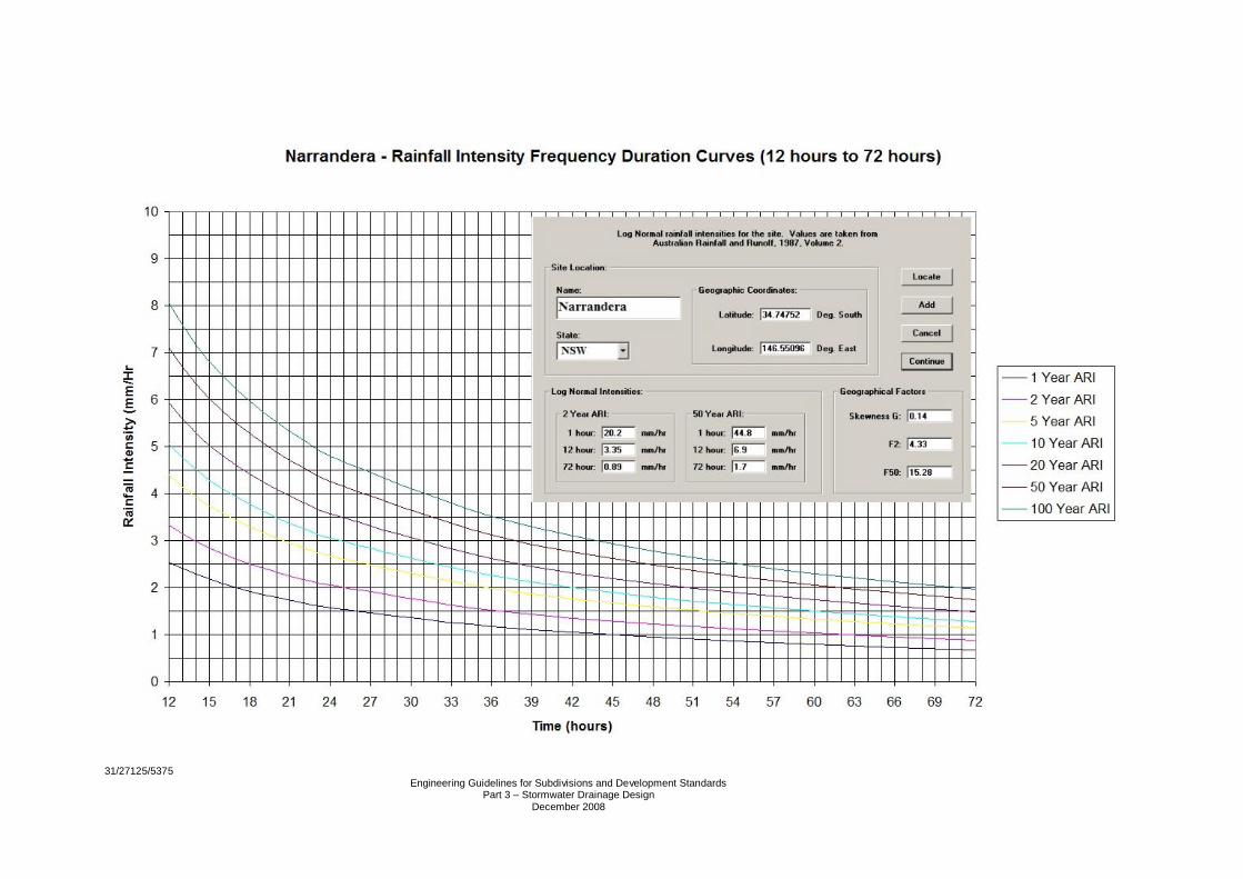
Narrandera – Rainfall Intensity Frequency Duration Table (12 hours to 72 hours)
Duration 1 Year
ARI 2 Year
ARI 5 Year
ARI 10 Year
ARI 20 Year
ARI 50 Year
ARI 100 Year
ARI
(hours) (mm/hour) (mm/hour) (mm/hour) (mm/hour) (mm/hour) (mm/hour) (mm/hour)12 2.54 3.32 4.39 5.05 5.93 7.11 8.0514 2.29 2.98 3.93 4.52 5.3 6.35 7.1816 2.09 2.72 3.58 4.11 4.81 5.76 6.5118 1.92 2.5 3.29 3.77 4.41 5.28 5.9620 1.79 2.33 3.05 3.49 4.08 4.88 5.5122 1.67 2.17 2.85 3.26 3.81 4.55 5.1324 1.57 2.05 2.67 3.06 3.57 4.26 4.836 1.18 1.52 1.98 2.26 2.62 3.12 3.5148 0.95 1.23 1.58 1.8 2.09 2.48 2.7860 0.8 1.03 1.32 1.5 1.74 2.05 2.372 0.68 0.88 1.13 1.28 1.48 1.75 1.96

31/27125/5375 Engineering Guidelines for Subdivisions and Development StandardsPart 3 - Stormwater Drainage Design
GHD
105 Hume StreetWodonga VIC 3690 AustraliaT: 61 2 6043 8700 F: 61 2 6043 8711 E: [email protected]
© GHD 2011
This document is and shall remain the property of GHD. The document may only be used for the purposefor which it was commissioned and in accordance with the Terms of Engagement for the commission.Unauthorised use of this document in any form whatsoever is prohibited.
Document Status
Reviewer Approved for IssueRevNo. Author
Name Signature Name Signature Date
1 J Ellwood C Elliott C Elliott 10/2/11