engineering circuit analysis-ch3
DESCRIPTION
Engineering Circuit AnalysisTRANSCRIPT

Ch3 Basic RL and RC Circuits
3.1 First-Order RC Circuits
3.2 First-Order RL Circuits
3.3 Examples
ReferencesReferences: Hayt-Ch5, 6; Gao-Ch5;
Engineering Circuit AnalysisEngineering Circuit Analysis
3.1 First-Order RC Circuits
Key WordsKey Words:
Transient Response of RC Circuits, Time constant
Ch3 Basic RL and RC Circuits
Ch3 Basic RL and RC Circuits
3.1 First-Order RC Circuits
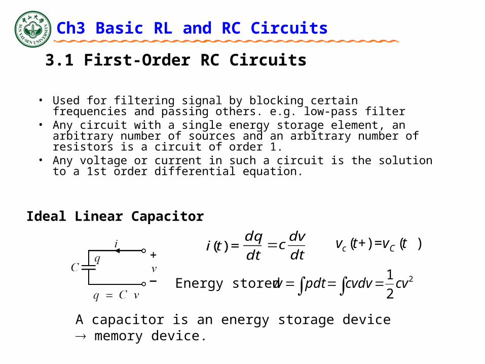
• Used for filtering signal by blocking certain frequencies and passing others. e.g. low-pass filter
• Any circuit with a single energy storage element, an arbitrary number of sources and an arbitrary number of resistors is a circuit of order 1.
• Any voltage or current in such a circuit is the solution to a 1st order differential equation.
Ideal Linear Capacitor
dt
dqti =)(
dt
dvc
2
2
1cvcvdvpdtwEnergy stored
A capacitor is an energy storage device memory device.
)(=)+( tvtv Cc
Ch3 Basic RL and RC Circuits
3.1 First-Order RC Circuits
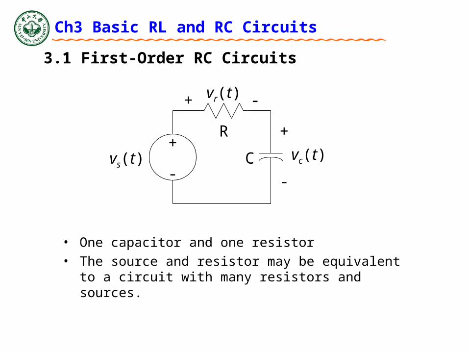
• One capacitor and one resistor
• The source and resistor may be equivalent to a circuit with many resistors and sources.
R+
-Cvs(t)
+
-
vc(t)
+ -vr(t)
Ch3 Basic RL and RC Circuits
3.1 First-Order RC Circuits
R
1
C
2
K
E
R
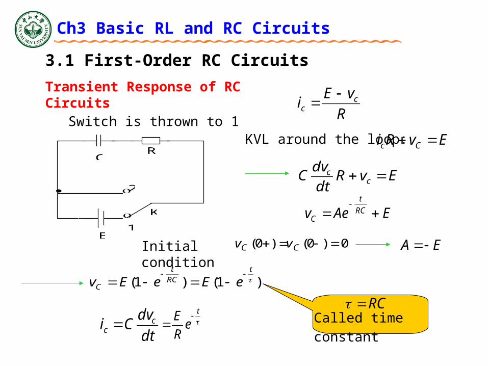
vEi cc
KVL around the loop: EvRi Cc
EvRdt
dvC c
c
EAev RC
t
C
Initial condition 0)0()0( CC vv
)1()1( t
RC
t
C eEeEv
dt
dvCi c
c t
eR
E
Switch is thrown to 1
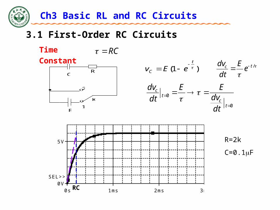
RCCalled time constant
Transient Response of RC Circuits
EA
Ch3 Basic RL and RC Circuits
3.1 First-Order RC Circuits
)1( t
C eEv
/tc e
E
dt
dv
0
0
t
ct
c
dtdv
EE
dt
dv
RCTime Constant
R
1
C
2
K
E
Time
0s 1ms 2ms 3ms 4ms 5ms 6ms 7ms 8ms 9ms 10msV(2)
0V
5V
10V
SEL>>
RC
R=2k
C=0.1F
Ch3 Basic RL and RC Circuits
3.1 First-Order RC Circuits
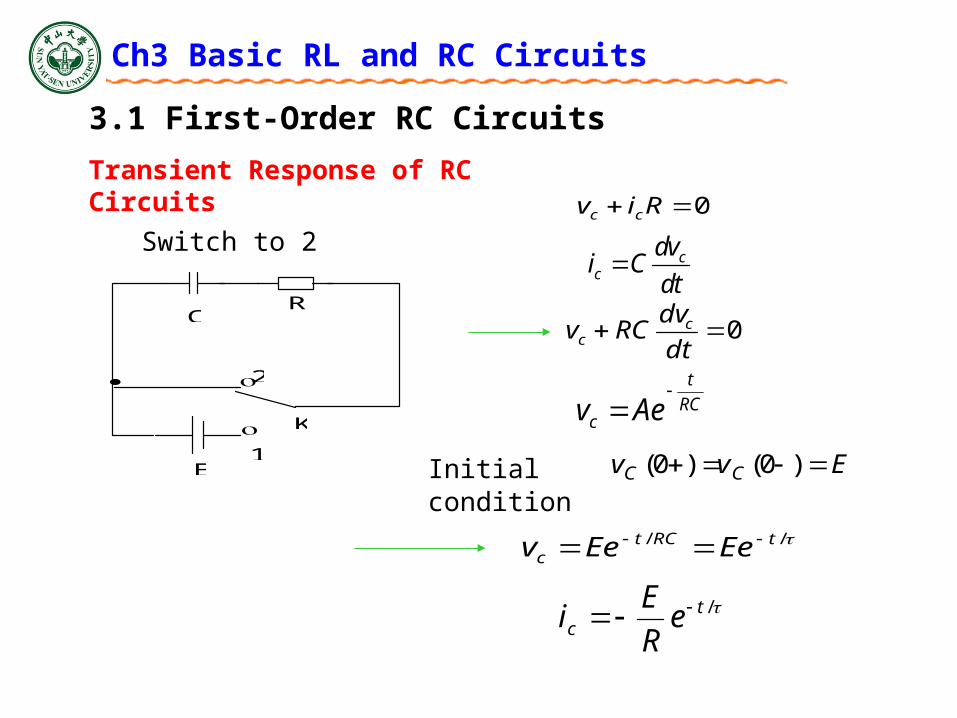
Switch to 2
R
1
C
2
K
E
RC
t
c Aev
Initial condition Evv CC )0()0(
0 Riv cc
0dt
dvRCv c
c
// tRCtc EeEev
/tc e
R
Ei
Transient Response of RC Circuits
cc
dvi C
dt
Ch3 Basic RL and RC Circuits
3.1 First-Order RC Circuits
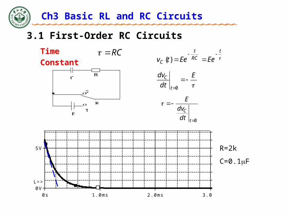
RCTime Constant
R
1
C
2
K
E
R=2k
C=0.1F
Time
0s 1.0ms 2.0ms 3.0ms 4.0ms 5.0ms 6.0ms 7.0ms 8.0msV(2)
0V
5V
10V
SEL>>
t
RC
t
C EeEetv
)(
E
dt
dv
t
C 0
0
t
C
dt
dv
E

Ch3 Basic RL and RC Circuits
3.1 First-Order RC Circuits
Time
0s 0.5ms 1.0ms 1.5ms 2.0ms 2.5ms 3.0ms 3.5ms 4.0ms 4.5ms 5.0ms 5.5ms 6.0msV(2) V(1)
0V
2.0V
4.0V
6.0V
Ch3 Basic RL and RC Circuits
3.2 First-Order RL Circuits
Key WordsKey Words:
Transient Response of RL Circuits, Time constant
Ch3 Basic RL and RC Circuits
3.2 First-Order RL Circuits
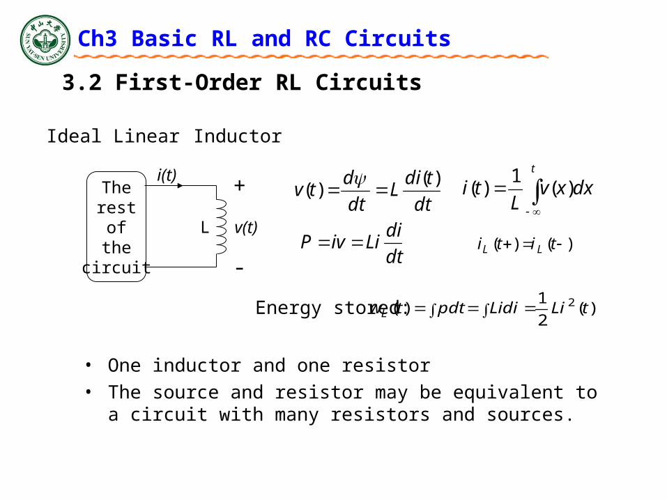
Ideal Linear Inductor
i(t)+
-
v(t)
Therestofthe
circuit
Ldt
tdiL
dt
dtv
)()(
t
dxxvL
ti )(1
)(
)()( titi LLdt
diLiivP
)(2
1)( 2 tLiLidipdttwL Energy stored:
• One inductor and one resistor
• The source and resistor may be equivalent to a circuit with many resistors and sources.

Ch3 Basic RL and RC Circuits
3.2 First-Order RL Circuits
Switch to 1
R
1
L
2
K
E
dt
diLvL
KVL around the loop: EviR L
iRdt
diLE
Initial condition 0)0()0(,0 iit
Called time constant RL /
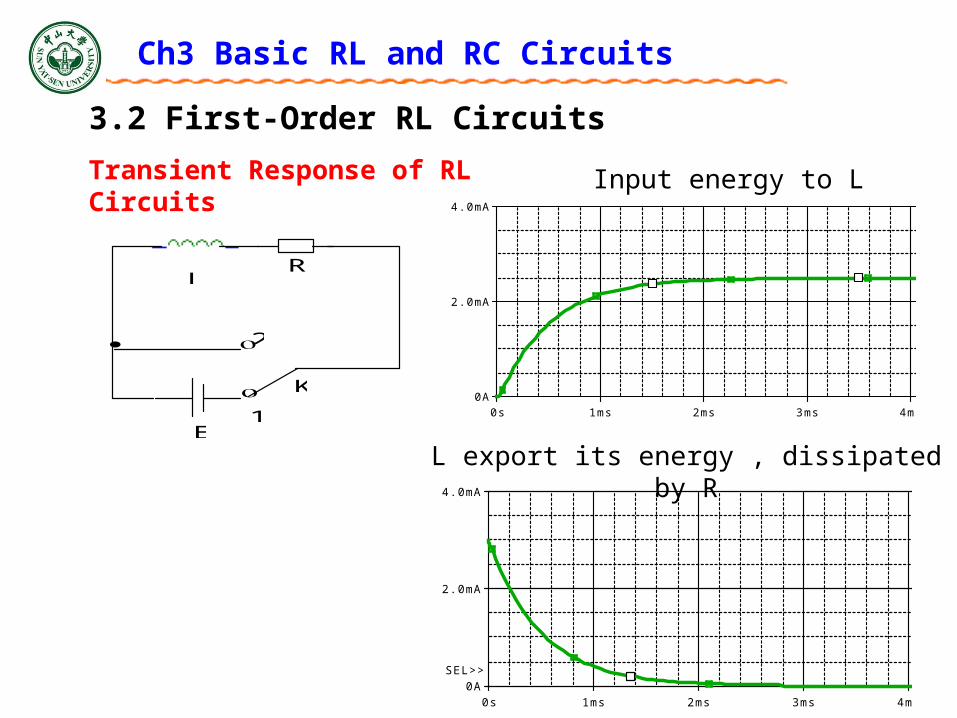
Transient Response of RL Circuits
/
/
/
1
)1(
)1()1(
ttL
Rt
L
R
L
tR
ttL
R
EeeL
R
R
ELe
R
E
dt
dL
dt
diLv
eEiRv
eR
Ee
R
Ei
Ch3 Basic RL and RC Circuits
3.2 First-Order RL Circuits
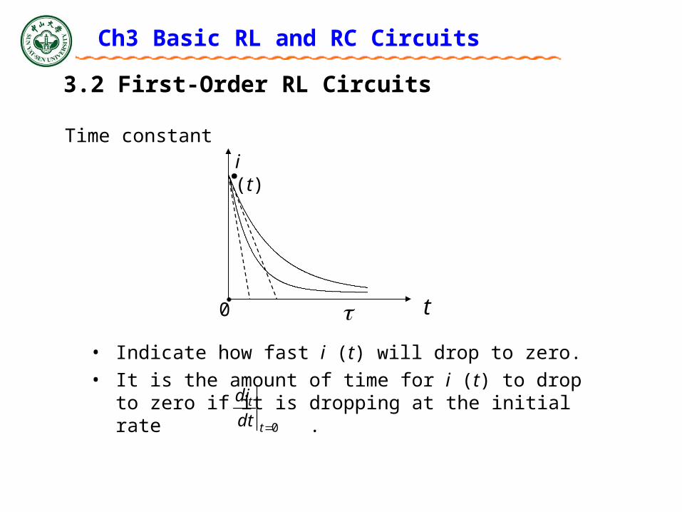
Time constant
• Indicate how fast i (t) will drop to zero.
• It is the amount of time for i (t) to drop to zero if it is dropping at the initial rate .
t
i (t)
0
.
0t
t
dt
di

Ch3 Basic RL and RC Circuits
3.2 First-Order RL Circuits
Switch to 2
tL
R
Aei
dtL
R
i
di
iRdt
diL
0
Initial conditionR
EIt 0,0
/ttL
R
eR
Ee
R
Ei
Transient Response of RL Circuits
R
1
L
2
K
E
0
0
0
0
0
: 0
:
1
ln
i t t
I
i t tI
t t
i I i t
Rdi dt
i LR
i tL
tL
R
I
ti
0
)(ln
tL
R
eIti
0)(
Ch3 Basic RL and RC Circuits
3.2 First-Order RL Circuits
R
1
L
2
K
E
Transient Response of RL Circuits
Time
0s 1ms 2ms 3ms 4ms 5ms 6ms 7ms 8ms 9ms 10msI(L1)
0A
2.0mA
4.0mA
SEL>>
Time
0s 1ms 2ms 3ms 4ms 5ms 6ms 7ms 8ms 9ms 10msI(L1)
0A
2.0mA
4.0mA
SEL>>
Input energy to L
L export its energy , dissipated by R
Ch3 Basic RL and RC Circuits
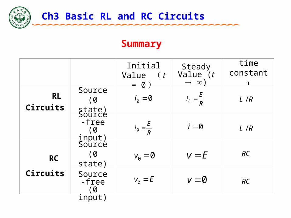
Initial Value ( t = 0)
Steady Value (t )
time constant
RL
Circuits Source(0 state)
Source-
free(0 input)
RC
Circuits
Source(0 state)
Source-free
(0 input)
00 iR
EiL
R
Ei 0 0i
00 v Ev
Ev 0 0v
RL /
RL /
RC
RC
Summary
Ch3 Basic RL and RC Circuits
Summary
The Time Constant
• For an RC circuit, = RC
• For an RL circuit, = L/R
• -1/ is the initial slope of an exponential with an initial value of 1
• Also, is the amount of time necessary for an exponential to decay to 36.7% of its initial value
Ch3 Basic RL and RC Circuits
Summary
• How to determine initial conditions for a transient circuit. When a sudden change occurs, only two types of quantities will remain the same as before the change. – IL(t), inductor current– Vc(t), capacitor voltage
• Find these two types of the values before the change and use them as the initial conditions of the circuit after change.
Ch3 Basic RL and RC Circuits
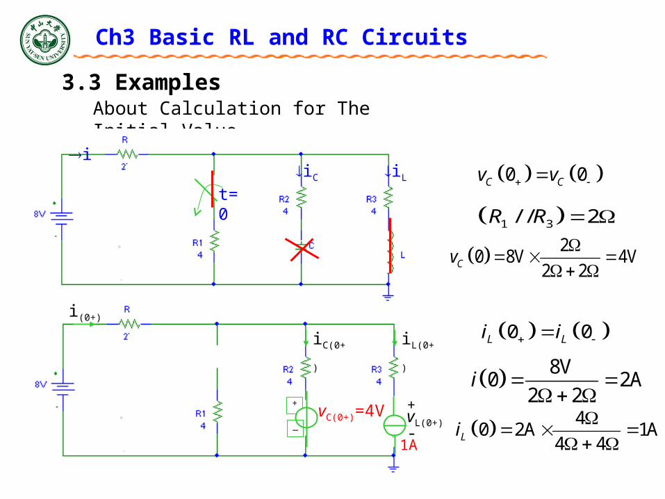
About Calculation for The Initial Value
iC iL
i
t=0
+
_
1A
+
-vL(0+)
vC(0+)=4V
i(0+)
iC(0+) iL(0+)
3.3 Examples
1 3/ / 2R R
20 8V 4V
2 2Cv
8V0 2A
2 2i
40 2A 1A
4 4Li
0 0C Cv v
0 0L Li i
Ch3 Basic RL and RC Circuits
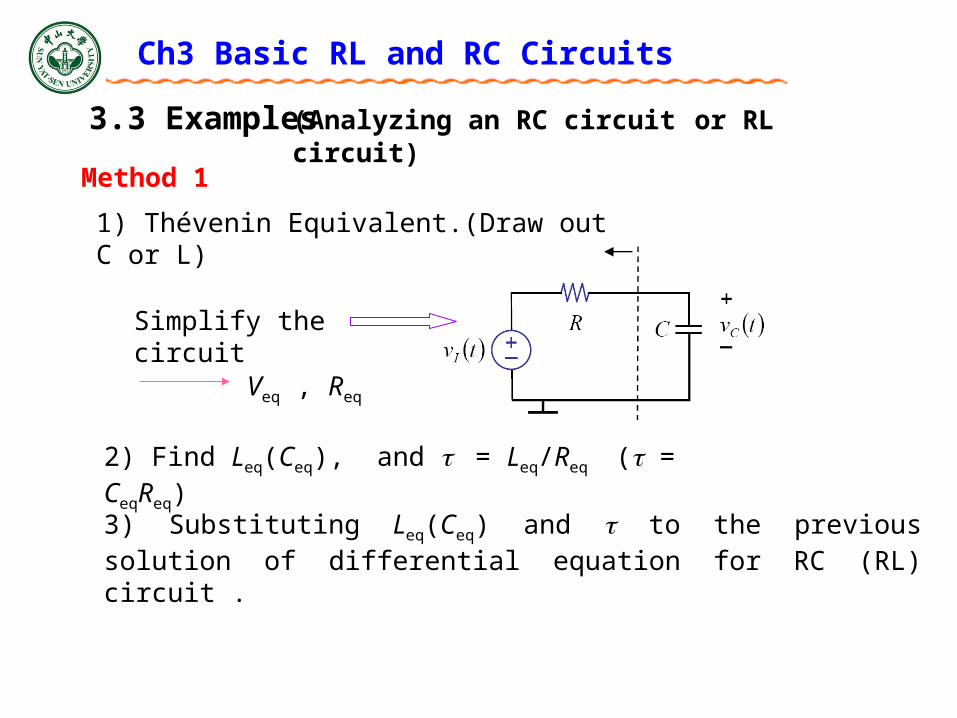
3.3 Examples
Method 1
(Analyzing an RC circuit or RL circuit)
Simplify the circuit
2) Find Leq(Ceq), and = Leq/Req ( = CeqReq)
1) Thévenin Equivalent.(Draw out C or L)
Veq , Req
3) Substituting Leq(Ceq) and to the previous solution of differential equation for RC (RL) circuit .
Ch3 Basic RL and RC Circuits
3.3 Examples
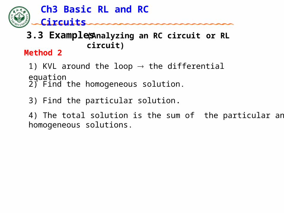
Method 2
(Analyzing an RC circuit or RL circuit)
3) Find the particular solution.
1) KVL around the loop the differential equation
4) The total solution is the sum of the particular and homogeneous solutions.
2) Find the homogeneous solution.
3.3 Examples
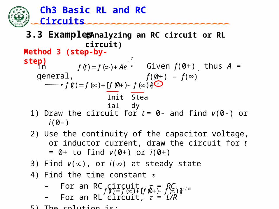
Method 3 (step-by-step)
(Analyzing an RC circuit or RL circuit)
1) Draw the circuit for t = 0- and find v(0-) or i(0-)
2) Use the continuity of the capacitor voltage, or inductor current, draw the circuit for t = 0+ to find v(0+) or i(0+)
3) Find v(), or i() at steady state
4) Find the time constant – For an RC circuit, = RC
– For an RL circuit, = L/R
5) The solution is: /)]()0([)()( teffftf
Given f(0+) , thus A = f(0+) – f(∞)
t
effftf
)]()0([)()(
Initial Steady
t
Aeftf
)()(In general,
Ch3 Basic RL and RC Circuits
Ch3 Basic RL and RC Circuits
3.3 Examples
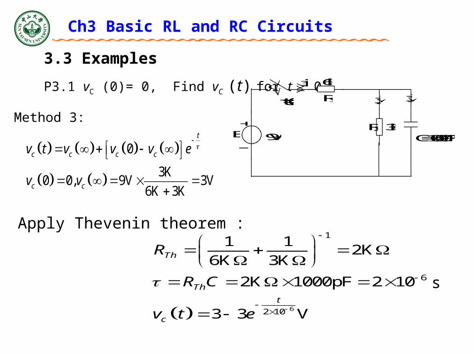
P3.1 vC (0)= 0, Find vC (t) for t 0. i1
6k
R1
R2 3k +
_ E
C=1000PF
pf
i2 i3 t=0
9V
Method 3:
0
3K0 0, 9V 3V
6K 3K
t
c c c c
c c
v t v v v e
v v
Apply Thevenin theorem :
6
1
6
2 10
1 12K
6K 3K
2K 1000pF 2 10
3 3 V
Th
Th
t
c
R
R C
v t e
s
Ch3 Basic RL and RC Circuits
3.3 Examples
vC
R2 3k
+
_ v
U
I
t=0
6V
C=1000PF
R1=10k
R1=20k
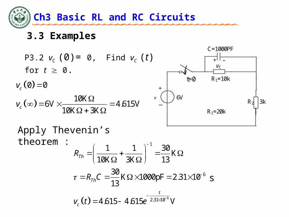
+ - P3.2 vC (0)= 0, Find vC (t) for t 0.
Apply Thevenin’s theorem :
6
1
6
2.31 10
1 1 30K
10K 3K 13
30K 1000pF 2.31 10
13
4.615 4.615 V
Th
Th
t
c
R
R C
v t e
0 0
10K6V 4.615V
10K 3K
c
c
v
v
s