engineering change notice 661800 i i pw. 1 c.'& bl....
TRANSCRIPT

S
ENGINEERING CHANGE NOTICE PW. 1 c.'&
2. ECN Category (mark one) 3. Originator's Name, Organization, MSIN. and Telephone No. 4. USQ Required?
0 O v e s @ NO
0 0
Supplemental J. Young, Nuclear Safety L Licensing, DirectRevision @ K7-97, 375-4510 Change ECN
Temporary
S!andby
Supc!;edure 0 sheet no. and rev.)
7. Bldg./Sys./Fac. No. 6. Project TitlelNo.NVork Order No.
RPP
9. Document Numbers Changed by this ECN (includes RPP I O . Related ECN No(s).
Cance!Noid r) RPP-5453. Rev. 0 N/A
661800 1 ........................................ I
I b l . ECN
5. Date
08/08/00
8. Approval Designator
N/A 11. Related PO No.
N/A > Ori inal Condition (Temp. EC& only)
- ~ . ~.
12d. Restore( or Stand
12a. Modification Work 12b. Work Package No. 12c. Modification Work Completed
0 Yes (fill out Elk. 12b) 0 No NA Blks. 12b. N /A N/A N/A
42c. 12d)
13a Description of Change Updated CAM availability analysis to support revised surveillance times in LCO 3.1.4.
Design AuthoritylCo Engineer Signature 8 Design AuthorityICo Engineer Signature 8 &e B i te
13b. Design Baseline Document? 0 Yes @ No
l4a. Jmtificaticn (mark one) 14b. Justification Details
Criteria j e @ Response to directed Change 5.2.2.a in the Safetv Evaluation Report for Q ~ ~ , ~ ~ ! , ,p,u 0
0 Environment..
Facility Deactlvdtion 0 As-Found 0 Facilitate Colist 0
the Implementation of an Alternatinq Control Strategy for LCO 3.1.4 Authorization Basis Amendment Packaqe, ORP Letter 00-SHD-057, K. T. French to M. P. DeLozier, dated June 15, 2000.
Const. Error/Omission 0 Desigi, ErruilOmission 0
15. Distribution (include name, MSIN, and no. of copies) FbCF SIPMp
.,,,. y-... 4'<... ,. ..
!D: STA
A-790&012-1 A-7900-013-2 (10197)

- I I 1. ECN (use no. from 00. 1)
6 Design Verification Required
r " ,
Page2of 2 166180; ENGINEERING CHANGE NOTICE
17 Cost lmpan 18 Schedule Impact (days) ENGINEERING CONSTRUCTION
@ No 1 Savings o $ N/A Savings 0 $ N/A
0 Yes 1 Additional 0 5 N/A Additional 0 $ N / A I Improvement 0 N/A Delay 0 N/A
SDDIDD
Functional Design Criteria
Operating Specification
Criticality Specification
Conceptual Design Report
Equipment Spec.
Const. Spec.
Procurement Spec.
Vendor Information
OM Manual
FSARISAR
Safety Equipment List
Radiation Work Permit
Environmental imoact Statement
0 SeismiclStress Analysis
0 StresslDesign Report
0 interface Control Drawing
0 Calibration Procedure
0 Installation Procedure
0 Maintenance Procedure
0 Engineering Procedure
0 Operating Instruction
0 Operating Procedure
0 Operational Safety Requirement
0 IEFD Drawing
0 Cell Arrangement Drawing
0 Essential Material Spectfication
0 Fac Proc SamD Schedule
Tank Calibration Manual
0 Health Physics Procedure
0 Spares Multiple Unit Listing
0 Test ProceduresISpecification
Component index
0 ASME Coded Item
Human Factor Consideration
0 Computer Software
0 Electric Circuit Schedule
0 ICRS Procedure
0 Process Control ManuaVPian
0 Process Flow Chart
0 Purchase Requisition
Tickler File
En, ronrnenta Permi 0 nventory Aa,ameni Request 0 organ zal on nas oeen no1 f eo of olner affenea ooc.rnenls imeo oe OH
3 Olner Affened Docdnenls (NOTE DocGrnents sleo oe OH w no1 oe rev sea oy i n s ECN , S gnatbres Deiow nolcale that the sgn ng
0 0
0 0 0 0 0 0 0 0 U 0 0
0 Environmental Report 0 Inspection Plan 0 0
- Document NumberIRevision Document NumberlRevision Document NumberlRevision
N < , " e
4pprovals Signature Date
O b gn Authority
8 9 b
QA ' Safety
Signature Date
Design Agent
PE
a.4
Safety
Design
Environ
Other
-Y
Signature or a Control Number that tracks the Approval Signature
ADDlTiONAL
A-7900-013-3 (10197

DISTRIBUTION SHEET
RPP-5453, Availability Analysis of the Ventilation Stack CAM
Page 1 of 1 To
Project TitlelWork Order Date August 02, 2000 Distr i h u t i o i i
EDT No.
J. M. Z r i q s b y
E. ('. tieui~.iaii
E . (1. Tnor r i e
Inter1 ock System I FCN N" 661 Rnn
R1-44 X
R1-43 X
R 1 - 5 6 X
Name Attach'/ EDT/ECN Text 1 Attach. 1 I MSlN With All Text Only Appendix 1 Onlv 1 Only
R. J . Cast1 I R1-44 I X I I I
i. T. W~iliams I R1-44 I X I I I
A-6000-135 (10/97)
.- _.

RPP-5453, Rev. 1
Availability Analysis of the Ventilation Stack CAM Interlock System
J. Young C H Z M HILL Hanford Group, Inc. Richland, WA 99352 U.S. Department of Energy Contract DE-AC06-96RL13200
EDT/ECN: 6 6 1 8 0 0 UC: 2030 Org Code: 74F00 Charge Code: 109311 B&RCode: N / A Total Pages: /+a Keywords: Authorization Basis, AB, Availability, Continuous Air Monitor Surveillance, System
Abstract: Ventilation Stack Continuous Air Monitor (CAM) Interlock System failure modes, failure frequencies, and system availability have been evaluated for the RPP. The evaluation concludes that CAM availability is as high as assumed in the safety analysis and that the current routine system surveillance is adequate to maintain this availability credited in the safety analysis, nor is such an arrangement predicted to significantly improve system availability.
TRADEMAR& DISCLA MER Reference nere n 10 any specfc commercal proauct process. or servnce ay liane name traoemam manufander. of othew se. aoes not necessar y Consld..te of mply Is enaorsement. recommendat on of favor ng oy me J n lea Stales Government or any agency thereof or 1s contranors or s.bcontranors
Pr intea n tne Ln tea Slates of Amerca To oala n copes of In s aoc.menl contact Document Control Serv ces P 0 Box 950 Ma slop d6-08. R.cn ana WA 99352 Phone 1509) 372-2420 Fax (509) 376-4989
- Release Stamp
Approved For Public Release
A-6400-073.1 (10/97)

RPP-5453 REV 1
Availability Analysis of the Ventilation Stack CAM Interlock System
J. M. Grigsby
E. 0. Thorne
J. Young
G&P Consulting, Inc.
Tekton Resources, Inc.
Pacific Northwest National Laboratory
Date Published August 2000
Prepared for the U S . Department of Energy
Hanford Group, Inc. Richland, Washington
Contractor for the US. Department of Ener y Office of River Protection under Contract D h X 6 - 9 9 R L 1 4 0 4 7
Approved for Public Release; Further Dissemination Unlimited

(1) Document Number
Page 1 o f 1 RECORD OF REVISION
RPP-5453
(2) T i t l e
Availability Analysis o f t h e Ventilation Stack CAM Interlock System
(3 ) Revision
I-- +- -
CHANGE CONTROL RECORD
I I I
A-732O-UO5 (08 /91 ) WEF168

RPP-5453 REV 1
This page intentionally left blank.
.. 11

RPP-5453 REV 1
CONTENTS
I
1.0 SUMMARY ........................................................................................................................ 1 1.1 PURPOSE ............................................................................................................... 1 1.2 CONCLUSION ....................................................................................................... 1
2.0 BACKGROUND ................................................................................................................. 1
3.0 ANALYSIS ......................................................................................................................... 2 3.1 ANALYSIS APPROACH ....................................................................................... 2
CAM FAILURE DATA ANALYSIS ..................................................................... 4 3.2 3.3 AVAILABILITY ANALYSIS RESULTS ............................................................. 4
4.0 REFERENCES .................................................................................................................... 5
APPENDIXES
A SUMMARY . HOURS OF SERVICE AND FREQUENCY OF CONTINUOUS AIR MONITOR FAILURES ....................................................................... A-1
B CONTINUOUS AIR MONITOR AVAILABILITY ANALYSIS ........................................ B-1
C AVAILABILITY ANALYSIS CASES FOR RPP CONTINUOUS AIR MONITOR INTERLOCK SYSTEMS ................................................................................... C-1
D COPY OF CONTRACTOR SURVEILLANCE REPORT RESPONSE S99-TOD-TF-042-FOl ................................................................................... D-1
E CHECKLIST FOR TECHNICAL PEER REVIEW .............................................................. E-1
LIST OF TABLES
1 RPP CAM System Failures ......................................................................................................... 4
2 Results of CAM Interlock System Availability Analysis ........................................................... 5
... 111

RPP-5453 REV 1
AB CAM FSAR HEPA MTBF MTTR RAM RPP TSR
LIST OF TERMS
authorization basis continuous air monitor Final Safety Analysis Report High Efficiency Particulate Air (filter) mean time between failures mean time to repair reliability, availability, and maintainability River Protection Project Technical Safety Requirement
iv

RPP-5453 REV 1
1.0 SUMMARY
1.1 PURPOSE
The purpose of this report is to perform an availability analysis of the River Protection Project (RPP) Ventilation Stack Continuous Air Monitor (CAM) Interlock System to support development of responses to Contractor Surveillance Report Response Number: S99-TOD-TF-042-FOl (included in Appendix D) items 2 and 3.
Item 2: Perform an engineering evaluation to determine failure modes that affect the intended safety function of the CAMS with regard to the interlock TSR and make necessary recommendations to correct any deficiencies.
Item 3: Analyze surveillance frequency to determine adequacy.
The analysis computes CAM availability based on current RPP surveillance and maintenance practice, with a 30 minute alarm of all CAM failures, and assuming the TSR surveillance is the only CAM surveillance conducted.
1.2 CONCLUSION
Ventilation Stack Continuous Air Monitor Interlock System failure modes, failure frequencies and system availability have been evaluated for the RPP. The evaluation concludes that CAM availability is as high as assumed in the safety analysis and that the current routine system surveillance is adequate to maintain this availability. Further, requiring an alarm to actuate upon CAM failure is not necessary to maintain the availability credited in the safety analysis, nor is such an arrangement predicted to significantly improve system availability. However, if CAM failures were only detected by the 92-day functional tests required in the Authorization Basis (AB), CAM availability would be much less than that credited in the safety analysis. Therefore it is recommended that the current surveillance practice of daily simple system checks, 30-day source checks and 92-day functional tests be continued in order to maintain CAM availability.
2.0 BACKGROUND
The safety function of the CAM Interlock System is to shutdown active exhaust ventilation on a high radiation reading to limit the release of airborne radionuclides after HEPA filters are damaged by an in-tank spray leak or HEPA failure due to a high temperature accident. The HEPA Filter Failure -Exposure to High Temperature accident analysis (Tank Waste Remediation System Final Safety Analysis Report [FSAR] Section 3.3.2.4.2) assumes that the interlock shuts down the ventilation flow within 10 minutes of detecting the high radiation condition. No explicit CAM Interlock System availability is stated in the safety analysis, however the assumed availability can be inferred from the analysis in FSAR Section 3.4.3.1.1,
1

I RPP-5453 REV 1
Failure of Controls for HEPA Filter Failure - Exposure to High Temperature or Pressure. This analysis states that frequency of the initiating event (HEPA failure due to high temperature) is “anticipated” (>lO.’/yr to I 10°/yr), while the frequency of the accident with failed controls (CAM Interlocks) is “unlikely” ( > ~ ~ / y r I 10-2/yr). This is nominally a factor of 100 reduction in the frequency, implying that the CAM Interlock system has a 99% probability of being available to mitigate this accident. The safety analysis assumption for CAM Interlock system availability is thus 0.99.
The question raised in Surveillance Number: S99-TOD-TF-042-FOl is, “can the CAM Interlock System meet its operability requirements if CAM Interlock System failures are not alarmed at a continuously manned ( e g . a control room manned 24 hours a day) location?” The CAM failure mode evaluation and surveillance frequency analysis question is clarified for this analysis to be, “Given the CAM Interlock System failure history, is it necessary to alarm CAM Interlock System failures at a continuously manned location in order to maintain the system availability credited in the safety analysis?”
This question is addressed by evaluating CAM Interlock System failure modes and failure rates over the past two years with system availability analysis and comparing the system availability to that credited in the safety analysis.
3.0 ANALYSIS
3.1 ANALYSIS APPROACH
The current RPP AB identifies the Continuous Air Monitor Interlock Systems as safety controls. The assessment of the effectiveness of the CAMs was based on the qualitative estimate that the CAMs reduced the accident frequency by about two orders of magnitude. This implies that the CAMS have an availability of 0.99. Availability is the probability that a system is in an operable condition at any random point in time.
An analysis was done to determine how accurate the qualitative assessment was and to identify what surveillance is required to achieve a CAM availability of 0.99. The analysis was based on two years of experience at RPP and the application of standard computational methods currently in use in system reliability, availability, and maintainability (RAM) analysis and for Probabilistic Risk Assessments (NUREG/CR-2300).
Availability can be computed by the following equation, where failures are discovered as a result of a surveillance activity (NUREG/CR-2300):
A = l - 1 / 2 h (1)
where:
A: systendequipment availability 1: systendequipment failure rate (failureshour)

RPP-5453 REV 1
t: surveillance interval (hours)
Alternatively, if there is relatively instantaneous failure detection, availability can be represented by (NUREGKR-2300):
A = MTBF/(MTBF + MTTR) (2)
where:
MTBF systedequipment mean time between failure (UA) MTTR: systedequipment mean time to repair (repair time includes failure detection and correction times)
Based on current RPP practice, equation (1) and equation (2) were both used to assess the current availability of the CAMs, and to determine if availability is driven more by the surveillance frequency or by the time needed to repair the system. CAM failure history was used to derive CAM failure rates. Because the CAMs are currently subject to three different types of surveillance actions, the CAM system was addressed as consisting of three subsystems, each made up of those components whose failure could be detected by a particular surveillance activity.
1. Equipment whose failures are detectable by the 24-hour simple system check surveillance;
2. Additional equipment whose failures are detectable by the 30-day source check surveillance; and
3. The remaining equipment whose failures are detectable by the 3-month Technical Safety Requirements (TSR) functional test surveillance.
Based on defining the CAM Interlock System as made up of three elements, the availability of the CAMs is computed as follows:
ACAM = (Ai)(Az)(Ad (3)
In practice, a number of different system checks are performed such as 6-hour operations checks, 24-hour Health Physics Technician checks, 15-day filter changes, etc. Some failures are alarmed. For the purposes of this availability analysis, alarmed failures and failures found during routine 6-hour operations checks are assumed to only be detected by the 24-hour (daily) simple system checks. Failures actually detected during 15-day filter changes are assumed to only be detected by the 30-day source checks.
Because the data available often does not include the exact time that the failure occurred, it has been assumed that failures occur, on average, in the middle of the surveillance interval. Sensitivity studies were performed to examine the impact of various proposed surveillance alternatives on CAM availability based on current failure experience. The cases examined were
3

I RPP-5453 REV 1
Found by Daily Found by System Check Source Check
Number of failures 70 9 Failure frequency 9.99E-5hr 1.28E-5hr
MTBF (l/h) 10,000 hrs 78,000 hrs 0.1
MTTR" 11 hrs 295 hrs Availability - .
(1) current practices, (2) reliance on the 92-day TSR functional test only, and (3) if CAM failures could be automatically alarmed and thus be instantaneously detected. In the last case, it was assumed that the alarm would detect failures for all surveillance activities listed previously. This assumption that the alarm could detect all of the failures detected by all hour surveillance activity is probably optimistic.
Found by Total Functional Test
0 79 1.43E-6' l . lE-4hr
- 8,870 hrs - 43.5 hrs
0.99Sb
3.2 CAM FAILURE DATA ANALYSIS
a Excludes the time when exhauster was shutdown (thus CAM was not required to be available)
E Conservatively assumes one failure. Fraction of the past two years that the CAMs have been available based on operating data.
3.3 AVAILABILITY ANALYSIS RESULTS
The availability analysis equations described above have been applied to the CAM operating data to study how system availability may be affected by changes in surveillance practices. The calculations for the specific cases analyzed are included in Appendix B, including inputs and outputs for each case. The results are summarized in Table 2.
As shown in Table 2, availability analysis predicts that the current practice of performing a daily simple system check, a 30-day source check, and a 92-day system functional test results in an availability of 0.993. This compares well with the observed availability of 0.995 shown in Table 1. Further, having CAM Interlock System failures alarm at a continuously manned
4

RPP-5453 REV 1 I location is not necessary to maintain availability greater than 0.99. Such an arrangement is not predicted to significantly improve system availability because the system availability is driven more by repair time than detection time. Finally, it is noted that most CAM failures are detected by the daily simple checks while no reported failures have been detected by the TSR functional tests, Relying only on the 92-day TSR surveillance is predicted to reduce system availability to 0.876.
Revising the CAM surveillance to extend the daily check to 48 hours (plus 25%) and the monthly to 31 days (plus 25%) still provides 0.99 availability as shown in Cases 4 and 5.
Table 2. Results of C
Immediate
on Alarmed
*0.5 hours is based on an alarm on CAM failure to a continuously manned location that detects all CAM failures.
4.0 REFERENCES
Contractor Surveillance Report Response, “Technical Safety Requirements,” Number S99-TOD-TF-042-FO1, B. J. Harp, US. Department of Energy, Richland Operation Office (DOE-RL), September 2, 1999.
FSAR, 1999, Tank Waste Remediation System Final Safety Analysis Report, HNF-SD-WM-SAR-067, Revision 1, Lockheed Martin Hanford Company, Richland, Washington.
NUREG/CR-2300, 1983, PRA (Probabilistic Risk Assessments) Procedures Guide: A Guide to the Perjomance of Probabilistic Risk Assessments for Nuclear Power Plants, American Nuclear Society, LaGrange Park, Illinois.
5

RPP-5453 REV 1
This page intentionally left blank.
6

RPP-5453 REV 1
APPENDIX A
SUMMARY: HOURS OF SERVICE AND FREQUENCY OF CONTINUOUS AIR MONITOR FAILURES
A-i

RPP-5453 REV 1
This page intentionally left blank.
A-ii

RPP-5453 REV 1
SUMMARY: HOURS OF SERVICE AND FREQUENCY OF CONTINUOUS AIR MONITOR FAILURES
(see Table A-1)
1. Time Unavailable begins with the time the incident was discovered, and ends with the completion of repairs, or shutdown of the fan.
2. Hours Unavailable is the Time Unavailable plus one half the surveillance interval when the actual failure time is unknown.
3. There are 40 Beta-Gamma Continuous Air Monitor locations used in this evaluation.
4. The evaluation starts with Occurrence Reports from October of 1997 and ends with reports from September 1999.
5. In cases where the date of repair is known, but the time is not available, the assumed completion time is taken as 30 minutes before the end of the next shift or midnight of that day.
6. Discovery Period indicates the method and periodicity of failure discovery.
Total CAM hours, 10197 through 9/99: 700800
Occurrence Reports: 58 CAM incidents: CAM hours unavailable: 3438
87 (including 8 incidents not involving a CAM failure)
Means of failure discovery: Ops (6 hr) 31 HPT (24 hr) 14 Craft (0 hr) 6 Cont Rm Ops (0 hr) 15 Testing (0 hr) 4 Source Chk (720 hr) 5 Filter Chg (336 hr) 4
Discovery Totals Hours Unavailable Hours / Incident - c24 hrs 70 782 hrs 11 - <720 >24hrs 9 2656 hrs 295 >720 hrs 0 0 0
A- 1
-

RPP-5453 REV 1
A-2
.. .-

RPP-5453 REV 1
0 N rL IC I . - c 2 0
O N
3 a I o x 5 5 z 00 z S U s s Z
In 0 Ln m m s z 2 r m s z s Z s Z
0 In 7. 7. (D m o r ii
A- 3
~

RPP-5453 REV 1
I I a v) 0 0
m
A-4

RPP-5453 REV I
m N
i iji1 In
0
9 O N ?. O N
m N
A-5

RPP-5453 REV 1
a . z
s
E!
a
2
z
0 a m
a, 0 C
2 0
L
6 0 z
A-6
t

RPP-5453 REV 1
A-7

RPP-5453 REV 1
E u o 0 [To 0 E
o n 2 - - (D
VI
E Z O C Y )
- - C Y )
- C Y )
0" 0 0 0 o n 3 3 8 0 0 0
0
N 0
0
0 0
r .. 0 3 v m !? ?i 0 .. 2 r
r 3 0 0 3 0 0
A-8

RPP-5453 REV 1
APPENDIX B
CONTINUOUS AIR MONITOR AVAILABILITY ANALYSIS
B-i

RPP-5453 REV 1
This page intentionally left blank.
B-ii

I RPP-5453 REV I
A 0 C
CAM - Availability Analysis 1
Formulas I I - Observed Availability 2 3
B-1

I RPP-5453 REV I
A 0 C
I I I
2 [Calculated Availability I I
B-2

RPP-5453 REV 1
APPENDIX C
AVAILABILITY ANALYSIS CASES FOR RPP CONTINUOUS AIR MONITOR INTERLOCK SYSTEMS
C-i
-

RPP-5453 REV 1
This page intentionally left blank.

RPP-5453 REV 1 I
CAM - Availability Analysis
Availability based on observation = (Total CAM hours -Total Time to Repair)/(Total CAM hours)
Operations Data CAM Hours 7.008E+05 Simple Failures 7.00E+01 Source Check 9.00E+00 Failures Functional Test Failures failures) Failures (total) 7.90E+01
Time to Repair 7.82E+02 (simple check) Time to Repair 2.66E+03 (source check) Time to Repair O.OOE+OO (Functional Test) Total Time to Repair 3.44E+03 MTBF (simple check) 1.001 E+04 MTBF (source check) 7.787E+04 MTBF (functional n/a test) MTBF (total) 8.871 E+03
MTTR (simple check) 1.1 17E+01 MTTR (source check) 2.951 E+02
Failure Frequencies
lambda source check 1.28E-05 lambda functional O.OOE+OO test
O.OOE+OO (there have been no observed functional test
lambda simple 9.99E-05
lambda (total) 1.13E-04
A(tota1) CAM 0.995 (availability based on fraction of time observed available)
c- 1

I RPP-5453 REV 1
CAM - Availability Analysis (1. Failures detected by simple check, 2. Failures detected by source check, 3. Failure detected by
system function check only)
Case 1 - CAM Availability - Based on Daily Simple Check, 30-Day Source Check, and a 92- Day Functional Test
Operations Data CAM Hours Simple Failures Source Check Failures Functional Test Failures Time to Repair (simple check) Time to Repair (source check) Time to Repair (Functional Test) MTBF (simple check) MTBF (source check) MTBF (functional test) MTTR (simple check) MTTR (source check)
Failure Freauencies lambda simple lambda source check lambda functional test
7.008E+05 7.00E+01 9.00E+00 l.OOE+OO (one is conservative relative to experience of zero)
7.82E+02
2.66E+03
O.OOE+OO
1.001 E+04 7.787€+04 7.008E+05 1.117E+01 2.951 E+02
9.99E-05 1.28E-05 1.43E-06
Surveillance Freauencies (hours) t simDle 24 (simDle surveillance check freauencv in hours) t soirce check t functional test
720 iCAM source check frequency'in hoirs) 2208 (system functional test surveillance frequency in
hours)
Availabilitv Based on Surveillance A(sur) simple 9.988E-01 A(sur) functional 9.954E-01 A(sur) interlock 9.984E-01 A(sur) CAM 0.993 (availability if determined by surveillance
frequency)
c-2

RPP-5453 REV I
CAM - Availability Analysis (Failures detected by simple check, source check, and system function check are alarmed)
Case 2 - CAM Availability - If All CAM Failures Were Alarmed to a Continuously Manned Station with Immediate Response
Operations Data CAM Hours Simple Failures Source Check Failures Functional Test Failures Time to Repair (simple check) Time to Repair (source check) Time to Repair (Functional Test) MTBF (simple check) MTBF (source check) MTBF (functional test) MTTR (simple check) MTTR (source check)
Failure Frequencies lambda simple lambda souice check lambda functional test
7.008E+05 7.00E+01 9.00E+00 l.OOE+OO (one is conservative relative to experience of zero)
7.82E+02
2.66E+03
O.OOE+OO
1.001 E+04 7.787E+04 7.008E+05 1.117E+01 2.951 E+02
9.99E-05 1.28E-05 1.43E-06
Surveillance Frequencies (hours) t simple t source check t functional test
Availabilitv Based on Time to
0.5 (failure alarm with 30-min response) 0.5 (failure alarm with 30-min response) 0.5 (failure alarm with 30-min response)
Abepair) alarm 9.989E-01 . , A(sur) functional 9.962E-01 A(sur) interlock I.OOOE+OO A(tota1) CAM 0.995 (availability determined by repair time)
c-3

RPP-5453 REV 1
CAM - Availability Analysis (1. Failures detected by simple check, 2. Failures detected by source check, 3. Failure detected by
system function check only)
Case 3 - CAM Availability - Based on 92 Day Functional Test Only
ODerations Data CAM Hours Simple Failures Source Check Failures Functional Test Failures Time to Repair (simple check) Time to Repair (source check) Time to Repair (Functional Test) MTBF (simple check) MTBF (source check) MTBF (functional test) MTTR (simple check) MTTR (source check)
Failure Freauencies lambda simple lambda source check lambda functional test
7.008E+05 7.00E+01 9.00E+00 l.OOE+OO (one is conservative relative to experience of zero)
7.82E+02
2.66E+03
O.OOE+OO
1.001 E+04 7.787E+04 7.008E+05 1.117E+01 2.951E+02
9.99E-05 1.28E-05 1.43E-06
Surveillance Freauencies (hours) t simple t source check t functional test
2208 (simple surveillance check frequency in hours) 2208 (CAM source check frequency in hours) 2208 (system functional test surveillance frequency in
hours)
Availabilitv Based on Surveillance A(sur) simple 8.897E-01 A(sur) functional 9.858E-01 A(sur) interlock 9.984E-01 A(sur) CAM 0.876 (availability determined by surveillance
frequency)

I RPP-5453 REV I
CAM - Availability Analysis (1. Failures detected by simple check, 2. Failures detected by source check, 3. Failure detected by
system function check only)
I
Case 4 - CAM Availability - Specified Surveillance Times (LCO 3.1.4)
Operations Data CAM Hours Simple Failures Source Check Failures Functional Test Failures Time to Repair (simple check)
Time to Repair (source check)
Time to Repair (Functional Test)
MTBF (simple check) MTBF (source check) MTBF (functional test) MTTR (simple check) MTTR (source check)
Failure Frequencies lambda simple lambda source check lambda functional test
7.008E+05 7.00E+01 9.00E+00 l.OOE+OO (one is conservative relative to experience of zero)
7.82E+02
2.66E+03
O.OOE+OO 1.001 E+04 7.787E+04 7.008E+05 1.117E+01 2.951 E+02
9.99E-05 1.28E-05 1.43E-06
Surveillance Frequencies (hours) t simple t source check
t functional test 2208 hours)
Availabilitv Based on Surveillance
48 (simple surveillance check frequency in hours) 744 (CAM source check frequency in hours)
(system functional test surveillance frequency in
A(sur) simple 9.976E-01 A(sur) functional 9.952E-01 A(sur) interlock 9.984E-01 A(sur) CAM 0.991 (availability determined by surveillance
frequency)
c - 5

RPP-5453 REV 1
CAM - Availability Analysis
(1. Failures detected by simple check, 2. Failures detected by source check, 3. Failure detected by system function check only)
Case 5 - CAM Availability - Specified Surveillance Times Plus 25% (LCO 3.1.4)
Operations Data CAM Hours Simple Failures Source Check Failures Functional Test Failures
Time to Repair (simple check) Time to Repair (source check) Time to Repair (Functional Test) MTBF (simple check) MTBF (source check) MTBF (functional test) MTTR (simple check) MTTR (source check)
Failure Frequencies lambda simple lambda source check lambda functional test
Surveillance Frequencies (hours) t simple t source check t functional test
Availability Based on Surveillance A(sur) simple A(sur) functional A(sur) interlock A(sur) CAM
7.008E+05 7.00€+01 9.00E+00 l.OOE+OO (one is conservative relative to experience of
zero) 7.82E+02 2.66E+03 O.OOE+OO
1.001 E+04 7.787E+04 7.008E+05 1.1 17E+01 2.951 E+02
9.99E-05 1.28E-05 1.43E-06
60 (simple surveillance check frequency in hours) 912 (CAM source check frequency in hours)
2208 (system functional test surveillance frequency in hours)
9.970E-01 9.941 E-01 9.984E-01
0.990 (availability determined by surveillance frequency)
C-6
- -

RPP-5453 REV 1
APPENDIX D
COPY OF CONTRACTOR SURVEILLANCE REPORT RESPONSE S99-TOD-TF-042-FOl
D-i
..

RPP-5453 REV 1
This page intentionally left blank,

RPP-5453 REV 1
RLF4482.2 110197)
Surveiliance Number: S99-TOO-TF-042-Fo1 Date: September 2, 1999
CONTRACTOR SURVEILLANCE REPORT RESPONSE
Page 1 of 2
DOE-RLAuIhor. B. J. Harp
SubjecUScope of Surveillance: Technical Safety Requirements
Surveillance Results: Safety class system operability requirenents were not met for the ventilation stack continuous air monitor ICAMI interlock system ILCO 3.1.4).
-: DOE Order'54B0.22, "Technical Safety Requirements," Attachment 1, Section 11, Paragraphs 2.4(h) and 2 . 5 are implemented through HNF-OS-WM-TSR-006, "Tank Waste Remediation System Technical Safety Requirements."
R.&acwd: Provided on Page 2 Discussion and Explanation: DOE Disc- and Ernb.a&h~: The definition of operable-operability 1°F-SD-WM-TSR-006) specifies that a system and all necessary attendant equipment shall be capable of performing the systems specified function. The functional requirement for the CAM 1°F-SO-WM-SEL-0401 specifies that the CAM must measure the sample flow stream and shutdown the.exhauster within 10 minutes of exceeding a preset radiation level. Continued on page 2
Root Cause: 4 0 - Design Problem; inadequate or defective design
-
Corrective Actions: 1. Perform an engineering evaluation to provide reasonable assurance of operability with ap- plicable compensatory actions (if needed) - Plant Engineering by 09/08/99, 2; Perform an engineering evaluation to determine failure modes that affect the intended safety function of the CAMS with regard to the interlock TSR and make necessary recom- mendations to correct any deficiencies - Equipment Engineering by 11/15/99. 3 . Analyze surveillance frequency to determine adequacy - Safety Analysis by 11/15/99. 4 . After completion of the engineer evaluation, develop a corrective action plan for implementation - Tank Farm Facility Operations by 12/27/99. Planned Completion Date: December 27, 1999
. Responsible Contractor Individual: C . DiFrango L 4 4 L . 6 c &,,
D- 1
- .

RPP-5453 REV 1
RL-F-5482.2 (101971
SuNeillance Number: S99-TOD-TF-042-FOl Date: September 2, 1999
Page t of z
CONTRACTOR SURVEILLANCE REPORT RESPONSE (CONTINUATION)
SURVEILLANCE RESULTS: - continued mkarouna: The computer automared Surveillance System ICASS) provided remote alarms, at a continuo&ly manned location, that detected equipment failures of the CAM interlock system. The CASS was reroved from service'based on the results of unreviewed safety question determinations (USQDsl TF-98-0629 and TF-99-0142. These USQDs provided the justification for eliminating CP.SS .
The TSR bases section for LCO 3.1.4 references.the calculation note that analyzed a HEPA filter failure accident and subsequent radionuclide release with a 10 minute duration. Based on this analyses. a 10 minuie ventilation system shutdown time for thcstack CAM interlock system was established.
The consequence of 'the 10 minute release was within acceptance guidelines.
DISCUSSION AND EXPLANATION: .- continued '
-: - continued Contrary to this functional requirement, the CAM is not capable of shutting down the exhauster within 10 minutes when a CAM equipment failure, e.g. vacuum pump, occurs. If an equipment failure occurred,.th= CAM could operate for up to 6 hours in an inoperable Status because the CAM is not interlocked to shutdown the exhauster and alarms are not monitored continuously. Therefore, the ventilation stack CAM interlock system does not meet operability requirements because the System 10 minute shutdown functional requirement cannot be met upon failure of a system safety class component.
LMHC Discuss ion and Ex~lanation : HNF-sD~Wl4-SEL-040, Section 6.1.1.3 States the "The CAM shall activate an interlock to shut down the exhauster within 10 minutes of detecting a radiation level that exceeds the preSet level. On CAM failure, the monitors must actuate an alarm and/or an interlock to shut down the exhaust system." These two sentences differentiate between CAM activation due to detecting radiation levels and CAM failures. The interlock and 10 minute requirements are applicable to CAM activation. CAM system failure is detected by remote monitors located in instrument buildings. an event occurring concurrent with a supporting system failure.
This is considered acceptable because of the low probability of
D-2

RPP-5453 REV 1
APPENDIX E
CHECKLIST FOR TECHNICAL PEER REVIEW

RPP-5453 REV 1
This page intentionally left blank.
E-ii
RPP-5453 REV 1
1
Practice1342901112 Publication Date 22Nov99
Attachment M - Sheet I of 1
FLUOR DANIEL NORTHWEST
TECHNICAL PEER REVIEWS
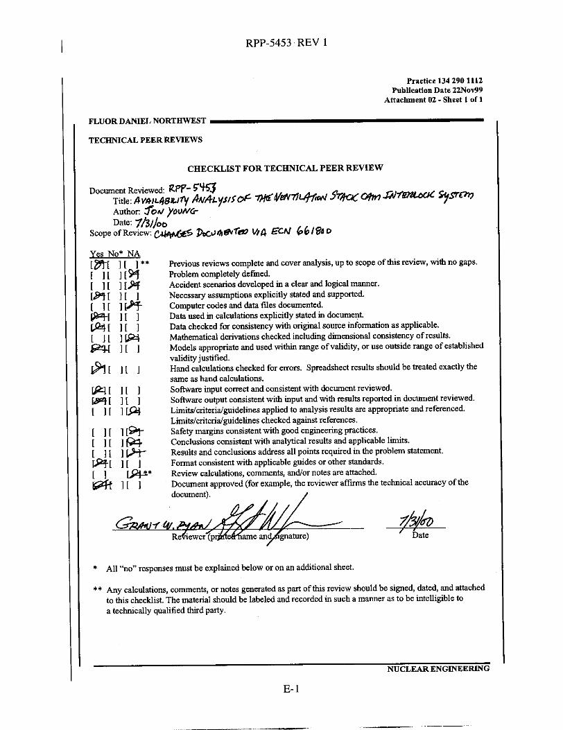
CHECKLIST FOR TECHNICAL PEER REVIEW
rP1 1 8 3 I 1
I [ 1 I [ 1 ILQ1
Previous reviews complete and cover analysis, up to scope of this review, with no gaps. Problem completely defmed. Accident scenarios developed in a clear and logical manner. Necessary assumptions explicitly stated and supported. Computer codes and data fdes documented. Data used in calculations explicitly stated in document. Data checked f a consistency with original snurce information as applicable. Mathematical derivations checked including dimensional consistency of results. Models appropriate and used within range of validity, or use outside range of established validity justified. Hand calculations checked for emors. Spreadsheet results should be treated exactly the same as hand calculations. Software input correct and consistent with document reviewed. Software output consistent with input and with results reported in document reviewed. Limitdcriteridguidelines applied to analysis results are appropriate and referenced. Limitsicriteridguidelines checked against references. Safety margins consistent with good engineering practices. Conclusions consistent with analytical results and applicable limits. Results and conclusions address all points required in the problem statement. Format consistent with applicable guides or other standards. Review Calculations, comments, andor notes are attached. Document approved (for example, the reviewer a f f m s the technical accuracy of the document). /
*
** Any calculations, comments, or notes generated as part of this review should be signed, dated, and attached
All “no” responses must be explained below or on an additional sheet.
to this checklist. The material should be labeled and recorded in such a manner as to be intelligible to a technically qualified third party.
NUCLEAR ENGINEERING
E- 1

RPP-5453 REV 1
This page intentionally left blank.
E-2
I__ _._