engineering and development division
TRANSCRIPT
. ·-~' .I .. ;
' "
AGN
r
Engineering and Development Division
AEROJET-GENERAL NUCLEONICS INDUSTRIAL REACTOR (AGNIR)
REACTOR PHYSICS TESTS
AN-1527 September 1966 r----------------·- --------- - ~
- NOTICE - E COPY THE ATTACHED FILES ARE OFFICIAL RECORDS OF THE DIVISION OF DOCUMENT CONTROL. THEY HAVE BEEN CHARGED TO YOU FOR A LIMITED TIME PERIOD AND MUST BE RETURNED TO THE RECORDS FACILITY BRANCH . 016. PLEASE DO NOT SEND DOCUMENTS CHARGED OUT THROUGH THE MAIL. REMOVAL OF ANY PAGE(S) FROM DOCUMENT FOR REPRODUCTION MUST BE REFERRED TO FILE PERSONNEL.
JlEGU.lATORY DOCKET TILE COPI DEADLINE RETURN DATE
RECORDS FACILITY BRANCH NUCLEON I CS
IFORNIA
l-

AGN
ENGINEERING AND DEVELOPMENT DIVI.§.!QN
AEROJET-GENERAL NUCLEONICS INDUSTRIAL REACTOR (AGNIR)
REACTOR PHYSICS TESTS
By
R. L. Tomlinson
AN-1527 August 1966
t ft N • : • • '· ·\ • , .._ ,"" _.., • • ..... ' •• ,,.; • ..~ ~ ; { ;· \a,( { ' " • •\ ,., ·•..\ ••• ' • ' .. i. ,
Approved by:~
R. H. Chesworth, Manager Engineering and Development Division
AEROJET 0 GENERAL NUCLEONICS A DIVISION OF AEROJET-GENERAL CORPORATION
iii

[. I
AN-152 7
. .
AEROJET-GENERAL NUCLEONICS INDUSTRIAL REACTOR (AGNIR)
REACTOR PHYSICS TESTS*
by
R. L. Tomlinson·
ABSTRACT
_The Aeroj et-General Nucleonics Industr_ial Reactor (AGNIR)
achieved initial criticality on 9 July 1965. Following ini.tial
criticality, a series c:i.f neutronics and power calibration tests . .
were perfonned to characterize the reactor from both the physics
and thermodynamics sta.ndpoints; A description of. th.e conduct a.nd ·····. •' . . . .. -·--·
significant results of this test program is ·presented herein,
. . *P.ublished by Aerojet-General .Nucleonics, San Ramo~,. Calif.
V
~-...
.;.

AN-1527
CONTENTS
I. INTRODUCTION
II. SUMMARY AND CONCLUSIONS
III. CONTROL AND SAFETY ROD SCRAM TESTS
IV. FUEL LOADING
v. VI.
A. INITIAL FUEL LOADING
B. SECOND FUEL LOADING
ISOTHERMAL TEMPERATURE COEFFICIENT
REACTIVITY MEASUREMENTS
A.
B.
c. D.
E.
F.
G.
H.
TECHNIQUES EMPLOYED
CONTROL AND SAFETY ROD CALIBRATIONS
FUEL AND REFLECTOR ELEMENT REACTIVITY MEASUREMENTS
GLORY HOLE MFASUREMENTS
DUMMY ELEMENT IRRADIATION CAPSULE MF.ASUREMENTS
FLUX WIRE HOLDER MEASUREMENTS
THERMAL COLUMN MEASUREMENTS
LARGE COMPONENT IRRADIATION BOX
I. XENON POISON EFFECTS
VII. POWER CALIBRATIONS
VIII. POWER COEFFICIENT MEASUREMENT
IX. NEUTRON FLUX TRAVERSES
REFERENCES
vii
Page
1
2
5
5
5
8
8
9
9
9
14
14
17
18
18
20
20
20
24
27
31
Figure Number
1
2
3
4
5
6
7
8
9
10
11
12
13
14
15
16
17'
18
19
20
Title
AGNIR Installation
AGNIR Core
AN-1527
FIGURES
AGNIR Core Loading Patterns
AGNIR Initial Approach to Criticality
AGNIR Isothermal Temperature Coefficient
AGNIR In-Hour Equation
AGNIR Shim Rod Reactivity Calibration
AGNIR Regulating Rod Reactivity Calibration
AGNIR Core Component Reactivity Worth as a Function of Core Position
Fuel Element Worth Versus Water in the AGNIR .Core
AGNIR Dummy Element Irradiation Capsule
Dry Irradiation Tube on Thermal Column
Large Component Irradiation Box
Xenon Poison Effects in AGNIR Versus Time
AGNIR Power Coefficient of Reactivity
AGNIR Pool Water Heating and Cooling Data (Without Heat Exchanger)
AGNIR Calorimetric Power Calibration
Axial Thermal Neutron Distribution in the AGNIR Core at a Power Level of 230 Watts
Radial Thermal Neutron Distribution in the AGNIR Core (230 Watts)
Radial Thermal Neutron Distribution in AGNIR Core and Thermal Column
viii
Page
3
4
6
7
10
11
12
13
15
16
17
19
21
22
23
25
26
28
29
30

AN-152 7
AEROJET-GENERAL NUCLEONICS INDUSTRIAL REACTOR (AGNIR)
REACTOR PHYSICS TESTS
I. INTRODUCTION
The Aerojet-General Nucleonics Industrial Reactor (AGNIR) achieved i.n
itial criticality at San Ramon, California, on 9 July 1965. It was the
twentieth reactor to be built and operated at the San Ramon site. The previous
nineteen were AGN-201 and -211 research and training reactors which were sold
commercially to research and educational institutions in the U.S. and Europe.
One 20 watt(t) AGN-201 reactor was in use at San Ramon for over eight years
until the AGNIR became available for company research activities.
The AGNIR is a 250 kw(t) pool-type reactor; it is fueled with uranium
zirconium hydride; and is water-moderated and water-cooled. The reactor is
licensed for general purpose neutron irradiations and isotope production. The
open-core design and the 10-ft-diameter, 23-ft-deep water pool was designed to
simplify the installation of special purpose irradiation loops, Both wet and
dry irradiation facilities are provided within the reactor in addition to
special laboratory space for the setup of electronic gear adjacent to the
reactor. In-pool storage is provided for 21 irradiated fuel or dummy element
irradiation capsules.
The reactor is operated from a control console which permits the oper·
a tor to fully view all operations performed at the top of the reactor po~il..
The facility is served by a 3-ton bridge crane; a mechanically positioned,
large component irradiation box can be actuated from the top of the reactor
pool.
1

AN-1527
The reactor core consists of zirconium-hydri_de fuel moderator elements
surrounded by graphite-filled reflector elements. The inherent safety of
this core design simplifies the procedure for obtaining licenses for experi
ments.
Reactor control is maintained by three boron carbide control rods. In
core irradiation facilities include a seven-element central exposure capa
bility; two 3-element exposure facilities; a glory hole; and nrultipurpose
dummy element irradiation capsules.
The facility consists of a high-bay metal-framed building 40 by 80 ft,
the low-bay portion of which is occupied by a general purpose laboratory; a
control room, and a change room. Six shielded pits are provided in the
facility for the storage of radioactive components, and a hot cell,which is
'licensed for 500 curie of Co-601 is also located with the reactor building. Non-
radioactive storage is provided above the low-bay area within access of the
three-ton bridge crane.
The initial physics tests on the reactor are reported herein. A cut
away drawing of the AGNIR installation is shown in Figure l; and a drawing of
the AGNIR core is shown in Figure 2. The facility was described earlier
(Ref. 1) as were the procedures used in performing the above-mentioned physics
tests (Ref. 2),
II. SUMMARY AND CONCLUSIONS
The initial criticality for the AGNIR was achieved with 63 altnninum-clad
TRIGA Mark I fuel elements. These fuel elements contained a total of 2265 gm
of U-235 in the form of uranium-zirconium hydrid~. The isothermal temperature
coefficient for the system was found to have an average value between 60 and
125°F of -0.15~/°F. All in-core void measurements indicated negative effects.
The power coefficient was measured to be -0.47¢/kw, resulting in a $1.17 in
itial reactivity deficit at 250 kw in addition to xenon, samarium, and fuel
burnup effects. The total worth of the control and safety rod system was
measured to be -$8.51. No data were obtained during these tests that measur
ably differ: from that presented in the AGNIR Hazards Summary Report (Ref. 1).
2
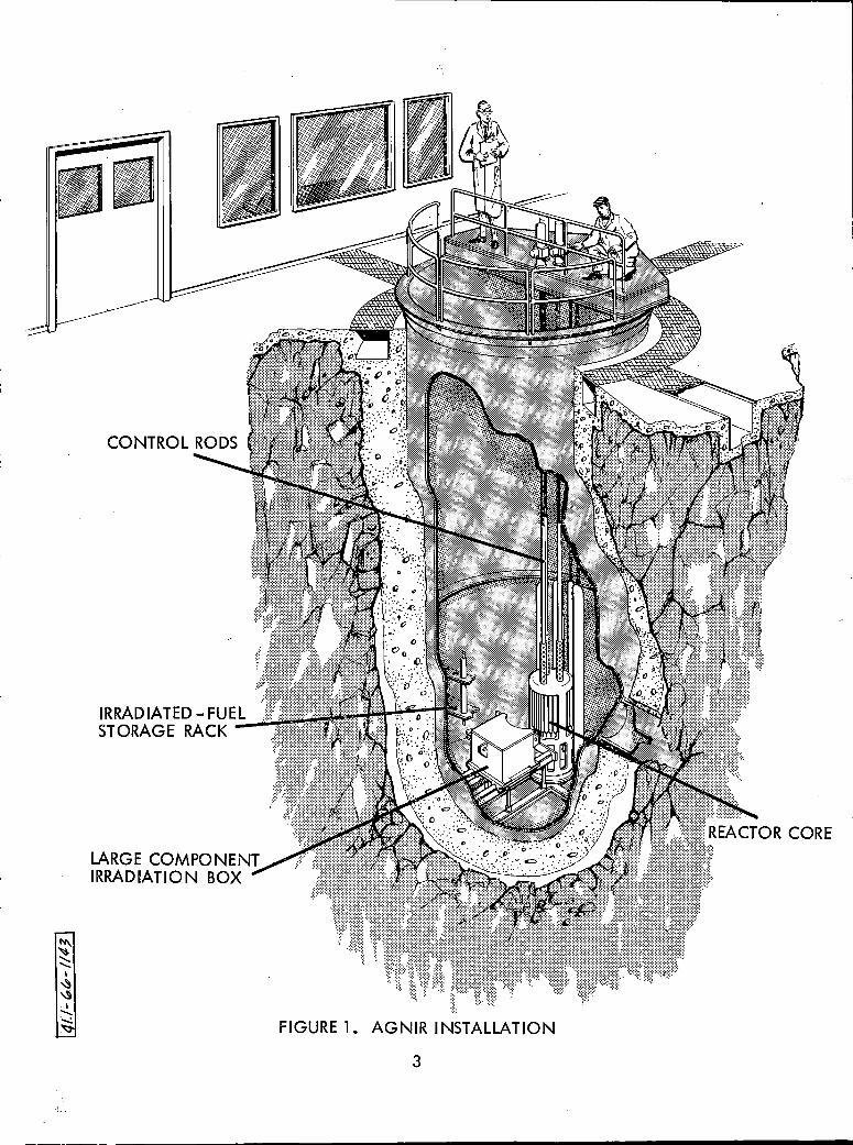
LARGE COMPONENT IRRADIATION BOX
FIGURE 1. AGNIR INSTALLATION
3

7 ELEMENT EXPOSURE FACILITY
3 ELEMENT EXPOSURE FACILITY
FIGURE 2. AGNIR CORE
4
DUMMY ELEMENT IRRADIATION SPACE
CONTROL INSTRUMENT CHAMBERS

AN-1527
III. CONTROL AND SAFETY ROD SCRAM TESTS
The experimental tests performed prior to the initial reactor critical
ity, and the four measurements subsequently performed as part of the quarterly
maintenance checks, indicate that the control rod drop times fall well within
the Technical Specifications of the reactor license. The Technical S.pecifi
cations state that the total rod drop time, including magnet separation time,
shall not exceed 600 milliseconds. For the three .control/safety rods the
magnet separation varied from 50 to 60 msec, while the total drop time varied
from 410 to 430 msec, A special relay rack panel was installed in the con
trol room to facilitate the easy measurement of the rod drop time with the aid
of a sweep oscilloscope and a series of microswitches. The panel also has
provisions for controlling a BF3
pulse counting assembly that was used for con
trol rod calibrations using the rod-drop technique, described in Section VI.
IV, FUEL LOADING
A. INITIAL FUEL LOADING
The initial fuel loading followed the reference procedures (Ref.2);
the fuel load consisted of 63 aluminum-clad TRIGA Mark I fuel elements and 23
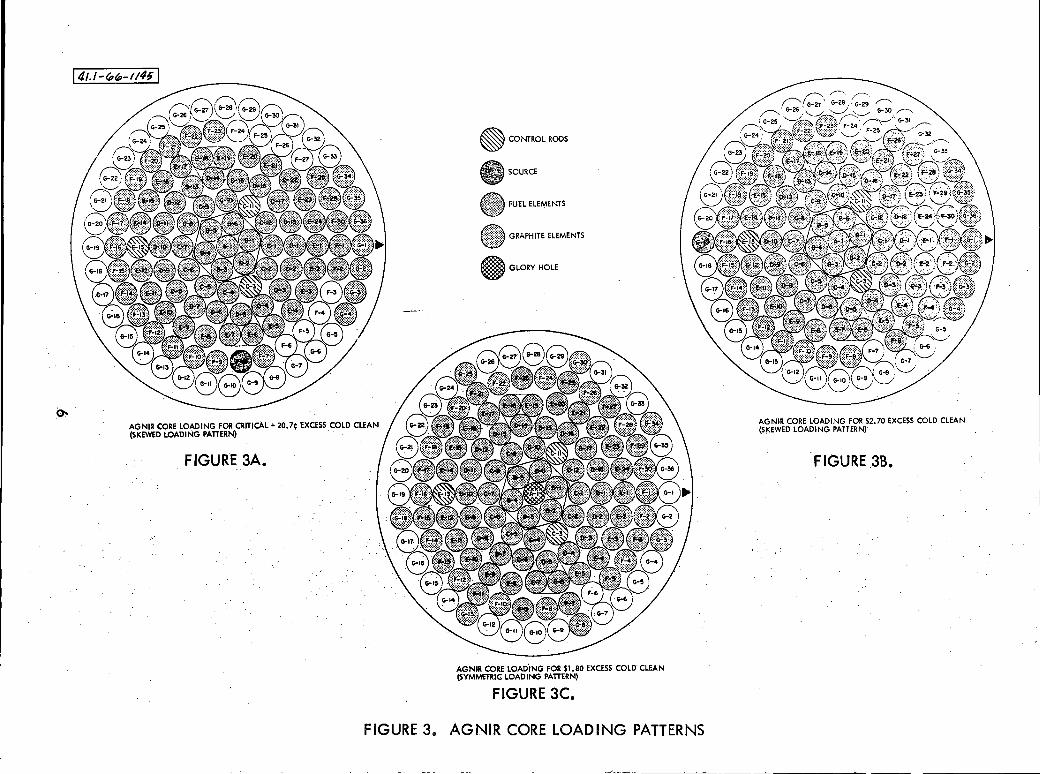
graphite-filled reflector elements. The loading was purposely skewed toward
the control instrumentation to provide the maximum signal to the reactor in
strumentation during the initial critical experiment. The initial loading
configuration is shown in Figure 3A.
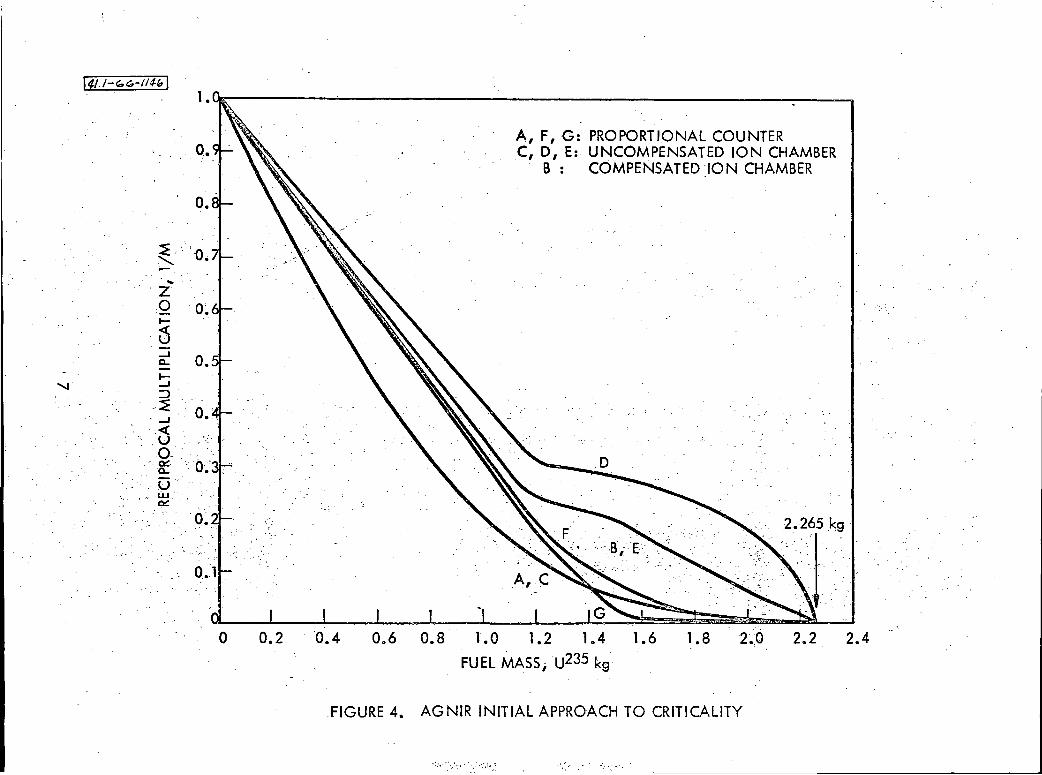
The nuclear instrumentation used during the initial critical ex
periment consisted of the normal four channels of reactor control instrumenta
tion; i.e., one BF3
pulse channel; one gamma-compensated ion chamber inter
mediate channel; and two uncompensated ion chambers used as power channels,
With no appreciable gamma background on the fuel, all four channels were on
scale providing useful infonnation. In addition, two additional BF3 pulse
channels and one uncompensated ion chamber were used during the critical ex
periment for a total of seven usable channels of nuclear instrumentation. A
plot of the multiplication versus fuel mass for the initial fuel loading
(Figure 4) reveals that the ion .chamber data proved more reliable than the
pulse counter data for this initial fuel loading. Cr.iticality was achieved
for the configuration within 35 grams of the value found in the initial
criticality calculation.
5
I 4u-r,,~-114; I
AGNIR CORE LOADING FOR CRITICAL+ 20,7~ EXCESS COLD CLEAN (SKEWED LOADING PATIERN) .
FIGURE 3A.
~ CONTROL RODS
SOURCE
FUEL ELEMENTS
9 GRAPHITE ELEMENTS
® GLORY HOLE
AGNIR CORE LOADING FOR $1.80 EXCESS COLD CLEAN (SYMMETRIC LOADING PATIERN)
FIGURE 3C.
FIGURE 3. AGNIR CORE LOADING PATTERNS
AGNIR CORE LOADING FOR S2.70 EXCESS COLD CLEAN (SKEWED LOADING PATTERN)
FIGURE 38.
141.,-'-~-,14" I
o.
o •
. ... ·z 0. 0~ 1-
6 _. CL
I_. ::>
-~ . _.
<( u . o.
o.
··. ·8: . ' Cl.' .-u·
0.1
·O
A, F, G: PROPORTIONAL COUNTER . C, D, E: UNCOMPENSATED ION CHAMBER
B : COMPENSATED ION CHAMBER
2.2rg
0.2 0.4 0.6 0.8 l.O 1. 2 1.4 1.6 1.8 2~:o 2.2 2.4
FUEL MASS, u235 kg·
.FIGURE 4. AGNIR INITIAL APPROACH TO CRITICALITY
, ' .. ,: .·.\;~ •: ----
AN-152 7
The fuel loading proceeded until a total of 69 fuel elements and
23 graphite elements were loaded into the AGNIR core for a total cold, clean
excess of $2. 70 (Figure 3B), The initial control rod calibrations were per
fonned during this loading. The final fuel loading for this configuration
is shown in Figure 3B. Preliminary coEe component reactivity measurements
were made with this configuration.
B. SECOND FUEL LOADING
On completion of the preliminary physics tests the AGNIR core
loading was adjusted to a nearly symmetric pattern with the "glory hole," a
dry exposure tube, located at the geometric center of the reactor (Figure 3C),
With 71 TRIGA Mark I fuel element.s and 23 graphite elements, the reactor had
a cold, clean excess reactivity of $1.80. The control rod calibrations, core
component reactivity measurements, neutron flux traverses, and power calibra
tions were performed with this basic core configuration.
V. ISOTHERMAL TEMPERATURE COEFFICIENT
The water-filled pool, which serves as~ radiation shield and coolant
reservoir for the AGNIR, contains approximately 13,000 gallons of water, The
water tank was used as a low-grade calorimeter for two thermal measurements:
1) power calibration of the reactor (see Section VII), and 2) the isothermal
temperature coefficient and cooling characteristics of the reactor pool tank.
Nineteen 220-volt immersion heaters, with a total measured power rating
of 23.9 ±. 0.1 kw, were inserted into the reactor grid using the fuel element
positions, while water was continuously circulated through a purification loop
at the rate of R:i 6 gpm. While maintaining the reactor. critical, the water tem
perature was monitored at five locations within the reactor pool tank. During
the tests, the water temperature was varied from 69°· to 125°F. The control
rods were calibrated, using both period and rod-drop techniques (see Section
VI), prior to measuring the temperature coefficient. As the water temperature
of the pool tank is changed, the actual position of the poison section of the
control and safety rods differs from the control/safety rod position indica
tors, because of thermal expansion of the rods. The discrepancy is appreci
able since the submerged portion of the control/safety rods is 20.5 ± 0.5 ft
during normal reactor operation, the uncertainty in length being due to the
8
AN-152 7
allowable l ft variation in the water level within the reactor pool tank, The
average value of the isothermal temperature co.efficient from 60° to 130°F is
-0.15¢/°F (Figure 5), The insertion of controi .rod poison as a: function of
bulk water temperature due to the linear expansion o.f the aluminum hanger rods
accounts for the entire coefficient within. the acci:lr~cy of the experimental ·
measurements.
VI. REACTIVITY MEASUREMENTS
A. TECHNIQUES EMPLOYED
A series of reactivity measurements we~e pe'rformed,. using positive
period and rod-drop techniques, The circuitry Ufled in performing these· . \ ' ' .
measurements is similar to that used ai: ~ther· :reacto~. i~stallauons; however,
an AGN-developed neutronics code* was used in r~ducing the data front the rod
drop measurements.
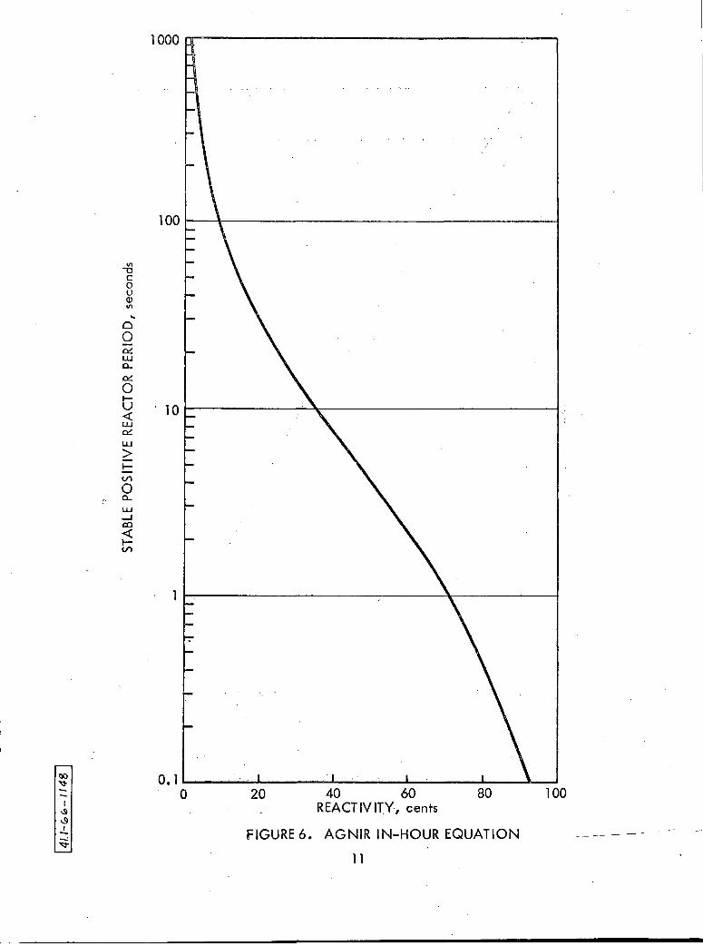
· · The range of positive periods meastir~d; using thifl technique, ,• . •,.
varied between 100 and 10 seconds, which. corresporid~ ,.tci :excess reacti vitie~
from 10 .to 40 cents. The reference pro,cedures (R~f'. ·2.)··were' used during the
measurements. The In-Hour Equation used in the period measurements is plotted
in Figure. 6.
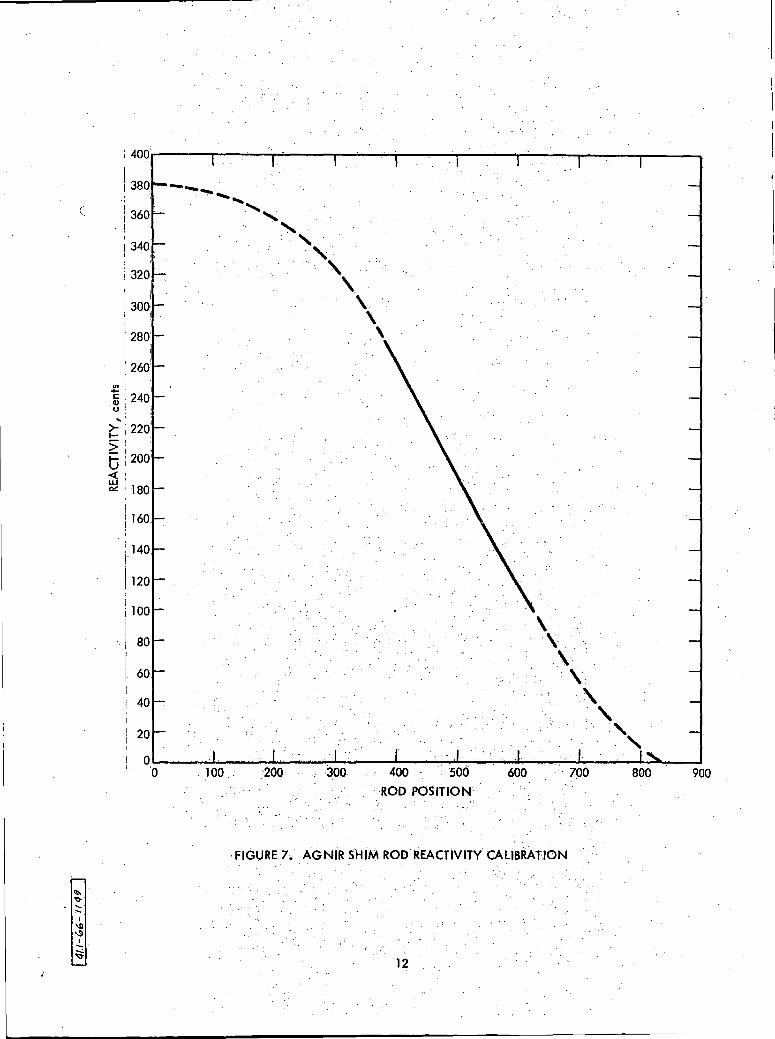
B. CONTROL AND SAFETY ROD CALIBRATIONS·
The la~ge reactivity worth of the AGNIR control ~nd safety rod
system ($8. 51 total) does not allow complete posit·i~e p~i;-iod calibration of ·
the ·sh~ and safety rods (appro~imately $3.80 and $3.75~· respectively), due to
the $3.00 license limitation and the safety. inte~lock o~ ~he safety rod. The ' . . . . . . . .
. safety rod is maintained in the "full "'-out" position ,du~ing ·reactor operation;
therefore, total worth measurements on all rods w~re 'obtained~. using rod;.drop
techniques. Intermediate points on the shi,;n and regulating rods were also ob-. ' ' ' .. ' ' . : . -
tained with rod-drop techniques and were ,found to ,be in: good ·agreement w:i. th· . .,. ' . ' . ,•
the period measurements. The calibr~tion, curves· obtai~ed u~in·g these tech
niques are presented in Figures 7 and 8 ..
In all reactivity measurements, .the accurat'e·determination of
criticality is very important. To assist in this' determinati~n, an expanded
scale was placed on the Channel 4 line~r power reco~d~r.: Using this recorder, ·*Internal Communication: T.P. Wilcox, DROP -· An IBM·Code to Solve for Reactor Power L~vels· After a Step Change in System ReactivHyJ AN.-COMP-134.
9

Or----,------.------~--,-,--..-----.------.-----....---
-1
-3
-4
l! C: Q)
-5 u .. w C) Z. <( J: -6 u >-!:::: ;:: ti :-1 <( w 0::
)
-8
-9
-10
-11
-12 ...... ------.................................. _._ ........ .,..-__ ...,... __ .............. ,,___....,_ _______ ___. 60 70 80 • ·· ·• · 90 • · 1 do . · · 11 o • 120 130 140
\ PO()[ Wfa;TER fEMPEAA~UR~: °F .
FIGURE 5.•. AGNIR iS()lHERMAL:TEMPERATURE COEFFICIENT ",· -· , . ·. ·' . . .
10 .
I 4r.H
olo-
u 48
I
STAB
LE P
OS
ITIV
E R
EA
CTO
R P
ER
IOD
, se
cond
s
0
.,, N
G
) 0
C
;::o m °' .
;::o
)>
m~
G
) )>
o
()
z -f
;::o
<
z .=
i -< I
... I
0 °'
0 (!
) 0
C
:::; ....
;::o
"' m
0 C
)>
(X
) -f
0
0 z
0 0
(.
: 4od.-----.----,,------,------,,--r--------,----'-----r-------,.......,i------.----, . I
1380 I :
. ,
/ 360
I
I 340. I
I
i 320'
\
300 I
280
: 26d
i ! 240 u' .
~ .. ! 220 >! 6 !200
~: ~ '180
I
\ 160.
! 140 I
I 120
100
80
60
40
20
-- "'!'"..._ ....
', ' ' .,·.
. ' \ \
\
'
\ ·\.·
\ .
\
' ' ' ' I Q....._ __ ......., ___ _....._.._ __ ....._ ___ _.__....._..,...,..,___,........-_ _,...._. __ .._..._...__ _ __,
'· ·o 100 : 200 300 400 · . soo 600 700 800 900
· ROD POSITION.
FIGURE 7. AGNiR SHIM ROD REACTIVITY' CALIBRATION
12

lOOr------r----'T"----r----r----,.----.------.----.
90
. 80
70
60
"' .... C Q) u ..
>- 50 !:::: > ti <( ·w co:: 40
30
20
10
100 200 300 400 500 600 700 800
ROD POSITION
FIGURE 8. AGNIR REGULATING ROD REACTIViTY CALIBRATION
13

AN-152 7
with its full-range zero suppression and 100-to-l amplification, minute drifts
in power can be readily detected and exact criticality accurately determined.
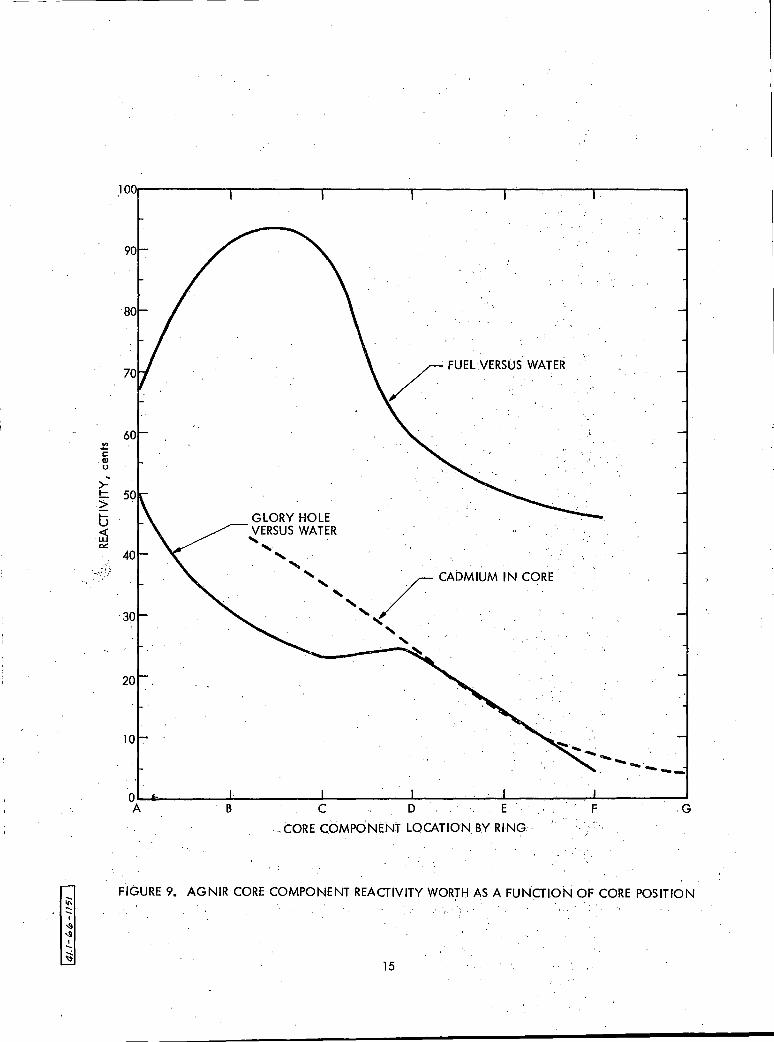
C. FUEL AND REFLECTOR ELEMENT REACTIVITY MEASUREMENTS
The reactivity worth of the AGNIR fuel elements, dry glory hole,
and dummy element irradiation capsule were evaluated as a function of ring
position, starting at the geometric center of the reactor grid plate. The
fuel measurements and dry glory hole measurements both were made with refer
ence to water, The actual worth measurements are plotted as a function of
ring position in Figure 9.
It can be seen that a fuel element in the center of the loading,
ring A, is worth less than that in rings Band C, which are almost identical
in worth. Since the AGNIR grid structure is basically a TRIGA grid with a
few minor modifications, this effect is not what might be expected, LP.riori;,.
however, in most TRIGA reactors the central core position is occupied with a
pulse rod or a norunovable glory hole and are therefore not available for the
placement of fuel, The TRIGA grid is undermoderated in the center and over
moderated at the edge. Starting at the center of the core, the hydr~gen/
uranium (235) ratio increases approximately linearly with radius. Multigroup
neutron transport calculations (Ref. 3, 4) performed on the actual AGNIR core
loading indicate a definite depression of thermal neutron flux in the center
of the core with a fuel element in the central location. With the central
fuel position flooded with water, the standard loading pattern for TRIGA
reactors, a normal thermal neutron distribution across the core is obtained
(Figure 10), Therefore, the shape of the fuel element reactivity curves shown
in Figures 9 and 10 are wqat would be expected from an analytical basis for
the AGNIR with and without a fuel element in the central position.
Graphite reflector elements were evaluated in the F and G rings
of the AGNIR core, The average value for these elements were found to. be 9
cents for the F ring, and 4 cents and for the G ring.
D. GLORY HOLE MEASUREMENTS
A special dry glory hole is available for various radiation ex
periments, This glory hole is equipped with an internal shield plug that is
used to reduce the radiation streaming in the vicinity of the control rod
14
"' "E Q) u ..
>-!:::: ~ t:; <( w 0,,:
:·-.\:)
60
40
30
20
lO
/ FUEL VERSOS WA m
GLORY HOLE VERSUS WATER
' ' ' ' . . ·.· ... ',' /· CADMIUM IN CORE
. ' ' . . . . . . . ~ . . . ' .
'
---OWio-----..1;_ ____ ..J_ ____ ...1.-""""."""---'--'~--L---"""".""".-L---""""."""""""."""---'
A B C D E F .G
... CORE COMPONENT LOCATION_ BY RING·
FIGURE 9. AGNIR CORE COMPONENT REACTIVITY WORTH AS A FUNCTION OF CORE POSITION I • ' • '
15

VI ,._ C (I)
u .. >-!:: > t-u <( LI.J ~
~ ....... .......
I ~ '9
I ..... -: "l::j,,
180
160
140
120
100
60
40
20
0 A B
----
G WATER IN POSITION A-1
0 FUEL IN POSITION A-1
C D E
CORE RING POSITION
FIGURE ·10· •. FUEL ELEMENTWORTH VERSUS WATER IN THE AGNIR CORE 16
F
AN-1527
drives at the top of the AGNIR pool. The glory hole can be positioned in
selected locations in each of the seven rings of the reactor core. The
reactivity of water versus the voided glory hole for these locations are
shown in Figure 9.
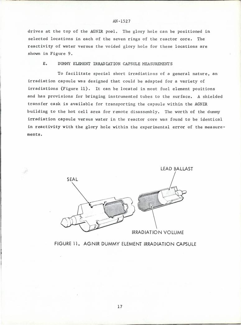
E. DUMMY ELEMENT IRRADIATION CAPSULE MEASUREMENTS
To facilitate special short irradiations of a general nature, an
irradiation capsule was designed that could be adapted for a variety of
irradiations (Figure 11), It can be located in most fuel element positions
and has provisions for bringing instrumented tubes to the surface, A shielded
transfer cask is available for transporting the capsule within the AGNIR
building to the hot cell area for remote disassembly. The worth of the dummy
irradiation capsule versus water in the reactor core was found to be identical
in reactivity with the glory hole within the experimental error of the measure
ments.
SEAL
IRRADIATION VOLUME
FIGURE 11. AGNIR DUMMY ELEMENT IRRADIATION CAPSULE
17

AN-1527
F , FLUX WIRE HOLDER MEASUREMENTS
The AGNIR core was designed t o allow flux traverses to be readi ly
per f ormed. A total of 22 holes, 0.313 in. in diameter, penetrate the up per
and lower reactor grid plates to allow the use of flux measuring wires, or
0 . 25 - i n.-diameter (or smaller) neutron-sensitive chambers to be placed in the
reactor core. Special aluminum holders for flux measuring wires have bee n
fabr ica ted for use in these holes. The reactivity of these holders, with
respect to water, is so low as not t o be a consideration in any flux mea sur e
ments ; however, special cadmium tubing used with many flux wire measuremen t s
(0 .050-in. ID by 0.090-in. OD) has an appreciable effect on the reactivi t y o f
the AGNIR. Cadm i um tubes, with a l e ngth of 26 in. and a weight of 6.63 gm,
were inserted in t he flux wire hold ers and their r eactivity worth deter mi ned .
These da ta ar e plotted in Figure 9 as a function of core position.
G , THERMAL COLUMN MEASURE11ENT S
The AGNIR thermal column consi s ts of a large block of graphite
containing five rows of 1.5-in. diameter holes arranged at increasing radii
from t he core. The rows are placed 6 in. apart, and each row contains seven
irrad i ation positions (Figure 12). Flux wire holder positions are located
near the centerline of each row to facilitate performing neutron flux traverses
of the thermal column assembly. Four slotted beams, two on each side, are pro
vided to allow experiments to be attached directly to the thermal column. Ex
tensions of these beams allow experiments to be placed inunediately adjacent to
t he reactor core. The assembly is located adjacent to the reactor core on
ta pered pins and remotely bolted to the bottom of the reactor pool tank. In
stallation and removal of the whole assembly is accomplished with the facility
crane and remote handling tools on a routine basis. Figure 12 also shows a
6-in. dry irradiation tube in one of the rear positions of the thermal column.
When the thermal column was installed, the worth of the column was
measured to be less than one cent positive with respect to water, due to the
2-in. gap between the reactor core structure and the thermal column which ef
fectively separates the reactivity effects of the thermal column from that of
the reactor core. Neutron flux traverses performed in the thermal column are
described in Section IX.
18

FIGURE 12. DRY IRRADIATION TUBE ON THERMAL COLUMN
19

AN-1527
H. LARGE COMPONENT IRRADIATION BOX
The large component irradiation box (Figure 13) consists of an
aluminum box with an internal volume of 8 cu ft. The walls of the box are
r e latively thin to eliminate excessive parasitic neutron absorption. The
box is pressurized with CO2 to 0.5 psi above the water pressure with the aid
of a relief valve attached to the top of the box. The CO2 is supplied
through aluminum and plastic tubing from a supply at the top of the reactor
poo l . Another tube is available for bringing electrical leads to the top of
t be pool if required for any experiment. The box is weighted with lead to
el iminate buoyancy. The box is remotely installed and bolted to a movable
t a ble at the bottom of the AGNIR pool. Similarly, the movable table is re
mot e ly positioned on tapered locating pins and bolted to the bottom of the
AGNIR pool.
When the void box was installed, a reactivity loss of 9 cents
was measured for the voided box with respect to water. The box is designed
to handle the irradiation of components and subsystems up to 2 ft in diameter.
I. XENON POISON EFFECTS
Since AGNIR operates at an average thermal neutron flux of about 12 2 13 2
4 x 10 n/cm -sec and peaks at about 10 n/cm -sec at the center of the
r eactor core, the effects of xenon poisoning on the operation are appreciable.
A test was run on the cold, clean reactor core to determine more specifically
the magnitude of these effects. The reactor was held at a constant power level
f 250 kw d 1 f 8S°F f 50 h d . h o an a constant poo~ temperature o or ours uring t e test.
Using the control rod calibrations, the effect of xenon poisoning as a function
of operating time was determined (Figure 14). Similarly, the poison worth of
xenon was measured following shutdown by making criticality determinations at
low power level and correcting for the power coefficient (Figure 15) and iso
thermal temperature coefficient effects (Figure 5). The results of these data
are also plotted in Figure 14.
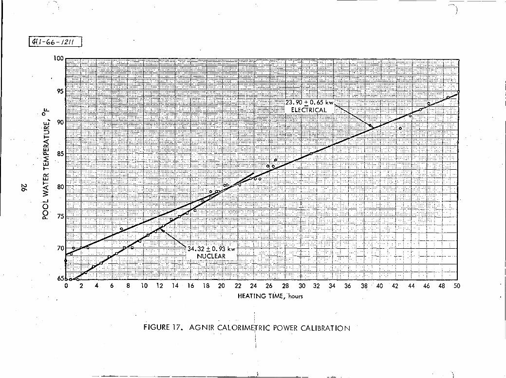
VII. POWER CALIBRATIONS
An accurate method of reactor power level determination for pool-type
reactors is electrical heat substitution (Ref. S). The reactor pool tank
(containing 13,000 gallons of water) was determined to be a fair calorimeter
between 70 and 95°F. As previously discussed in Section rv, nineteen 220-volt
immersion heaters (with a total measured power rating of 23.9 ±. O.l_kw) were
2.0

FIGURE 13. LARGE COMPONENT IRRADIATION BOX
21

I 4!.l-b'--IIS2 I
150
140
130
120
110
"' 'i: 100 Q) 0
' 90 :I: I-~
0 ?;
80
r..) >- 70 "' !:: ;;::: ti 60 < w ~ 50
40
30
20
10
0 0 4 8 12 16 20 24 28
TIME, hours
XENON BUILDUP FOLLOWING COLD, CLEAN STARTUP
XENON DECAY FOLLOWING SHUTUP FROM EQUILIBRIUM OPERATION
32 36
FIGURE 14. XENO N POISON EFFECTS IN AGNIR VERSUS TIME
40 44 48
!-,
~ C Q) u
' V) V)
0 ..J
>!::: :2:: t; <( w 00:
120..-----.-----.,---'--..------..-----,---,.--.,.,...----,.----,-----,
40
30
20
10
25 50 75 100 125 150 175
. REACTOR POWER LEVEL, kw
FIGURE 15. AGNIR POWER COEFFICIENT OF REACTIVITY
23
200 250

AN-1527
inserted into the reactor grid, using the fuel element positions, while the
water was continuously circulated through a purification loop at~ 6 gpm.
Sirtce the inlet to the purification loop is near the top of the reactor pool
tank and the discharge nea_r the bottom, this flow slowly .stir s the pool
water, thereby reducing temperature stratification within the tank. The
water temperature was monitored at five locations within the reactor pool
tank. Plots of the heating and cooling characteristics of the pool water tank
are shown in Figures 16 and 17. Once the 23.9 kw electrical heating curve was
obtained, the reactor was flux-mapped at low power* and the corresponding read
ings of the Channels 3 and 4 ion chambers were made. The flux traverses were
made at an estimated power level _of 160 w, based on thermal flux integration
techniques. Using this estimated power as a ba·sois, a scale factor was applied
to the ion chamber readings corresponding to a power level of 23.9 kw. A 24-
hr nuclear heating run was performed at these ion chamber readings. The actual
pow~r level was found to be 34.32 ± 0.93 kw, based on the previously performed
electrical heating data; therefore, the initial flux mapping was performed at
230 watts instead of the estimated 160 watts (Figure 17).
Subsequent nuclear heating runs were performed at 200 kw and 250 kw
(Figure 16). Due to the increased heating rate over the initial calibration
runs, the heating curves at these power levels are practically linear and do
not show the effects of water evaporation that occurs at the lower heating 0 rates. At pool temperatures of 70 F, the water evaporation was found to be
about 0.5 gallons/hr; while at 125°F, the rate increased to 5 gallons/hr. The
cooling curve in Figure 16 clearly shows the operating limitations of the
AGNIR without its 250-kw heat exchanger.
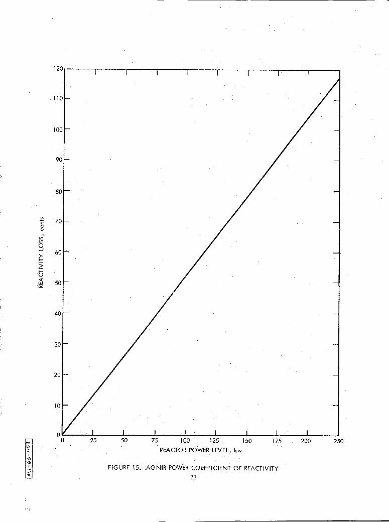
VIII ~WER COEFFICIENT MEASUREMENT
The power coefficient (i.e., the reactivity loss as a function of
reactor power) was measured at constant water temperature without xenon in
the core. Using the control rod calibration curves, the reactor power was
increased in 25-kw steps above delayed critical and the reactivity loss de
termined. A plot of the data is shown in Figure 15. The measured average
reactivity coefficient was found to be approximately -0.47¢/kw, for a total
.._g_activity loss at 250 kw of $1.17. *Internal Communication: V .R. Forgue, Gold Wire Flux Mapping of AGNIR, AGN
Chem Tech Memo No, 887, October. 1965.
24

I'-.) 0,
14-t.(-~~-1212'
u. 0 .. w ~ :::, I-<( ~ w a.. ~ w I-~ w I-<(
3: _J
0 0 a..
250kw ~.:_:_~...:..:..:.........c:..:.:.:.c.:c..~~=-c:~-+-:-,-c-,-±:-;-=-:-:-ci-::-::=:c~-:-:-:::-:t-:-,-:-:--;t-:----:-c:--:--:-r::-:-:-=-:-:=:cc:-=l=:,-.77'/:-:=:-:-:-:-t:c-:-c-:--:-:-:-r=:c-:-:-7)":-:-:-:-:c-=,--=-_ I -- : --:.:: : : .
---- Nu CL EAR _..;c___:____:..:_:_:___;___::'.'!"""C..:.:..:..:..:~::_+-:.~:.:.c.:.:..:.:..:.=;=.:.:,:-=+-'~.:.;-:=-:-?-:-'--:-'-'~--'--:-:-'-'-'F-~:-:-:-==+-:-:-7:-:-:-:::-:-:-'-:-=~~:---:-c---:--t:-,::--,-:-:-: ::tc: ::-"'.:: fc:-:: :'_ !-:---,: : :.,.....:~.: L:--, -c-:-i_.
-! ·:,: --= . : :·:: !> ' ' t':: = :
1 Q01l----,!:_;____;;____;'---'c__;--'....:......;....:......;__:.___:_c:......;,.;----;...----'---1.:--'=-;,..-=-~-'-'-'----'----!--::--:---:----:---:-:-c--:--~:-:---::-c--;--,t . ' . . .. . • . . . . . . . . . . .
i ...:....;..._;__-_;_:_...c.:..:..:._:_.;__;_--"-'--'---'-,F-c-',..+-,---:-:--:-:---:-:-c~;:.; : .. ::C:: =::. (··. ·:: .. T : J: : i --~-'--.-!--.;:_: ,- ·-, = i -:Tc:=>:-::<=,,, : , -·:,==::: :::·., ·- ·· ... : .. = J: -::,, r,::,:
... :.:.···: .. ... .,
90
80Ul-:.:.__je----:---,;f!--~__;:-=-:1:...:...:,+;i_-'--':1.:.;__=1:..:.../.;.:1,...:.:::...:...=:~-'.:1+1'..:_\!,:..,::.:_:r;+-1~.:.:,:11-:-~:C.::::+-i~:,..:~:-'-=-~t'-':::.:Er::C.C,:-c'-,i~:CC.1E.1~:::-r~=-=:J~1if-'Cil'-':1;1"-'-t~~l~-':cir;:'-:::f.:.,,1t'-'-fi-'CC1:::c.:.~""f::*i·""i1:-:-:-:1:::.,..,;~-+:.;-:-:rC.:C:i:-=-;:c:-=1;.,...\-:-::1=.,...:r
7-t~-:-:):-:-:t:-:::~t--:-t:-:-1,-:-:~:-;-:-t::-::_~-:-~i:-:-:t:~ii1:-:-:[t:-:-:ti-:-r,.:l~-:-~~:-:-:\-:-:jti..,,.1:-::c-::);.,...~ft::t~-:-~t-:-1r:-:-:;;:ct1~-:-:-:,7.,;:-.::=
-· -;: • -:1 , : -~::: :!:;';i'!':l;:i:i;:::f ;~=;;~'l ~:;J~:f ;W~~i;'.;;: ;;~:,=;~::;'.;~f:lr ~'.';~: ~n:f ;';:;::::::=~~ •:'~': - -: = '.::r; •:,l~ '.: .,,.;: ,~~:: i:: :~'. ;!~;:~::: ~~r~m;;r~:;m'.~U ;~l:~;;r;~;;i:i~i;~;mm~~;~'.~~;~:,
601--_ .--__, __ : :f •; ,!::;::;:,!;::::=~: i:~~~~:;;~:;~c~:~i~~:t~,r~;;,;;~:~~J~'::: ~rn~~~~f :;;m~;t~c;;; ~:f •; :i~'::;: ! : : : -= ~;~~~~: :~: :: ;;=: :f:. • :[::;:t;::; [:~;:m;~<:i:;;~[~;: ;;[ =;~[~:::!'.~::;: ;• :!::_::~'. ::~;.[;;: -. _ i:::: ~:: · 0 20 40 60 80 100 · 120 140 160 180 200 220 240
HEATING TIME, hours
FIGURE 16. AGNIR POOL WATER HEATING AND COOLING DATA (WITHOUT HEAT EXCHANGER) . I
'; .I
u.. 0
... w
. O! :) I-<( O! w ·O..
-~
w I-O! w
"' I-
°' <(
3: --' 0 0 0...
'::ci· :: : ::: .; J/',: le 1 j.P',, :!'. :),;.J::;,/:;jc:'\'(:T:'=='=:Ti:1:(,: : (: :; -- -::',;:: !·': >J :::·:: ! --- :J:: ..... : i i . . . _L _____ i ____ _
70~;-1),>~: i : ! !~5.4·;~~i~k~1:: i i l : it : ; : __ ._ ; •- . '.- • : L--~------
65 '{::*r::':<; :: : .. i'.::'.;''.::kL::;;:=::=~~1::;:;.:-y,_;;:n-:~:~'.,:V:;~::=;;:''.'.i~:::i···:>.r:: ~- :';;.:~~ :·f ~:·I . ; ::::. ' . . ·j-:-: i ·:--: -- --0 2 4 6 8 10 12 14 16 18 20 22 24 26 28 30 32 34 36 38 40 42 44 46 48 50
HEATING TIME, hours
' i I
FIGURE 17~ I
AGNIR_ ~ALORIMEfRIC POWER CALIBRATION
.\ .
AN-1527
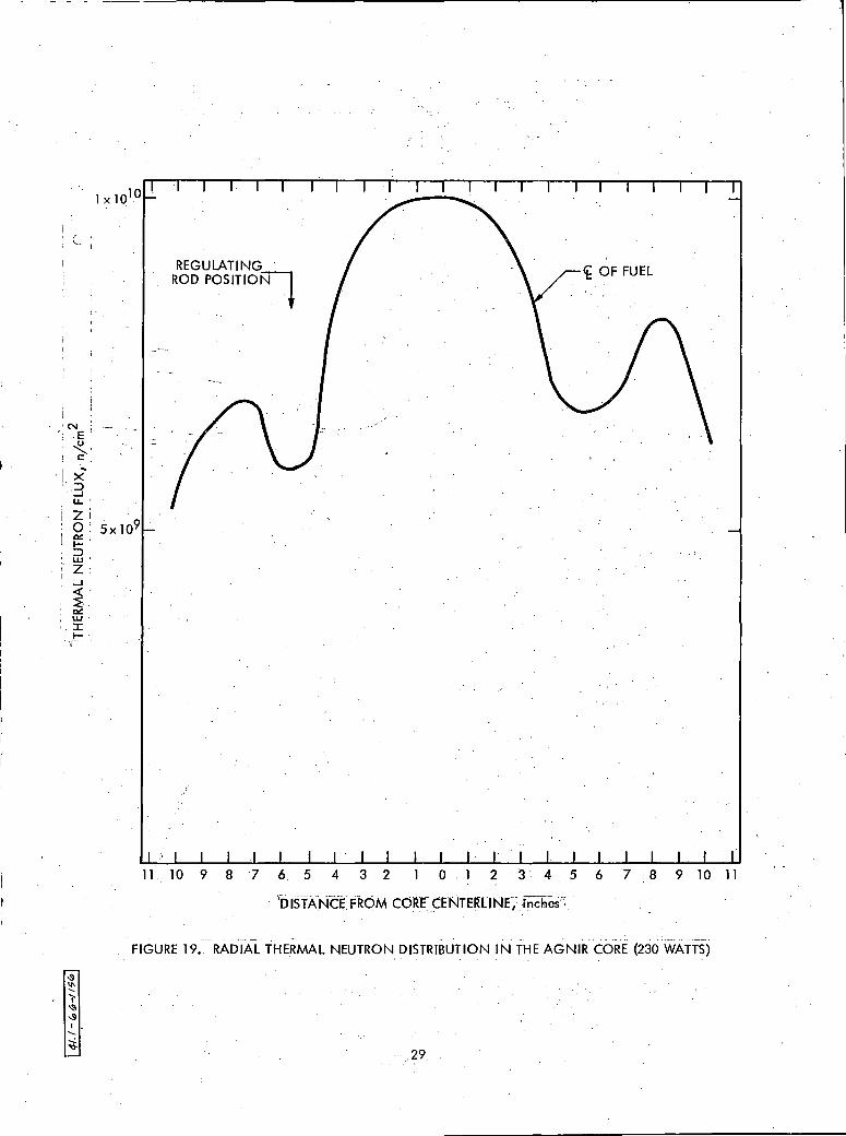
IX. NEUTRON FLUX TRAVERSES
The thermal neutron flux mapping of the AGNIR core and thermal column
was performed using 0.010 in. diameter gold wires inserted into the AGNIR
flux wire holders and irradiated in the AGNIR. core and thermal column, using
the 28 flux wire positions (22 in the core and 6 in the thermal column - see
Section VI-F). Epicadmium measurements were made, using 0.050 in. ID by
0.090 in. OD cadmium tubes with the 0.010 in. gold wires running axially down
the tubes. The 26Pin. long gold wires were cut into 2-in. increments and
wrapped around a dowel to form an 0.32 in. diameter ring and counted on a
scintillation counter that had been previously standardized with 0.002 in.
by 0.50 in. diameter gold foils by reference to a National Bureau of
Standards calibrated neutron flux. In regions of the AGNIR core where the
neutron flux changes rapidly with position, 1/2-in. long wires were used.
The 0.010 in. gold wire and the standard 0,002 in., 0.5-in. diameter gold
foils were cross-calibrated, using the AGN 201M reactor (basic AGN-201
reactor modified for 20-watt operation). A typical axial thermal flux plot
performed in the Band G rings of the AGNIR is shown in Figure 18, The B
ring represents the flux plot at the center of the core, while the G ring
represents the flux distribution in the reflector region. Figure 19 shows
the thermal neutron distribution radially across the AGNIR core at the center
line of the fuel, Figure 20 shows the thermal neutron distribution radia,lly
across. the centerline of the AGNIR. core and thermal column. The details of
the thermal neutron flux measurements.were documented earlier*.
*Internal Communications: V.R. Forgue, Gold Wire Flux Mapping of AGNIR, AGN Chem Tech Memo No, 887, October 1965.
V.R. Forgue, Flux Traverse in AGNIR Thermal Column~ AGN Chem Tech Memo No, 952, March 1966.
27

u (l) Vl I
N E ~
C: .. X ::::> __.
1 X 10 l Q ~----,----__.;.--,----.,..-~-....;..,r--.....----,----"T"""'---W
u..
Z 5x 10⁹ 0 0,:: I::> w z __. <(
~ 0,:: w :c I-
0 4 8 12 16 20 24 28 DISTANCE BELOW REACTOR TOP GRID PLATE, inches
FIGURE 18. AXIAL THERMAL NEUTRON DISTRIBUTION IN THE AGNIR CORE AT A POWER LEVEL OF 230WATTS
28
·-·--------
(_
'N: .EI ~.
! C . .. ·[ X'
3, U.. I
l X 1010
z;. o· 5xl09 ~-1-:::, W.'
'I Z; !
...I' <( '
~ ~ w :::c I-'
REGULATING ROD POSITIO~
(f OF FUEL
11 10 9 8 "7 6 5 4 3 2 0 . l 2 3 ·. 4 5 6 7 8 9 l O 11
. iijjsi'Xr,rtt FROM CORE CENTERLINr~~ ,fncliies';I. . . .• . '' ,. ... \ . ' .... ' .
. . FiG.URE 19 •. RADIAL THE,RMAL NEUTRON DISTRIBUTION IN THE AGNIR--CQRE '(230 'WATTS) l • • • • • • • •
.- .. 2-9.

GRAPHITE REFLECTED
WATER REFLECTED
1012.__·~1--~-·-R_E_A_._cr_o_R~~~·-·-11.-i:=-~~---T-·H_E_R_M_A_L_c_o~Lu_M~N----~--~M
u . Q)
"' I N
E ~
C .. X ::, ....I LL 1011 z 0 O! I-::, w z . ....I <( ~ O! w :c I-
. 9 ld ._._ ___ ..._ _______ __._ __ ___,....___._ ...................... __ ...... __ ....... ________ ....._ __ .... . · 15 10 5. 0 . 5· 10 15 • 20 25 30 35 40
DISTANCE FROM REACTOR CORE CENTERLINE, inches .
FIGURE 20. RADIA~ TH~RMAL NEUTRON DISTRIBUTION IN AGNIR CORE AND THERMAL COLUMN .. 30

AN-1527
REFERENCES
1. R. L. Newacheck, tl al., Aerojet-General Nucleonics Industrial Reactor,
Hazards Summary Report, AN-1193, Aerojet-General Nucleonics, San Ramon,
California, September 1964
2. R. L. Tomlinson, Aerojet-General Nucleonics Industrial Reactor (AGNIR)
Critical Experiments and Power Calibration, AN-1406, Aerojet-General
Nucleonics, San Ramon, California, April 1965
3. L. D. Connolly, Los Alamos Group-Averaged Cross Sections, LAMS-2941,
IASL, July 1963
4. B. G. Carlson, e. E. Lee, and W. J, Worlton, The DSN and TDC Transport
Codes, LAMS-2436, LASL, October 1959
5, R, L. Tomlinson, SNAP Shield Test Experiment Reactor Physics Tests,
NAA-SR-7368, Atomics International, Canoga Park, Calif,, July 1962
31