engineering a device to locate golf...
TRANSCRIPT
Engineering a Device to Locate Golf Balls
Ryan Smolenski
Stem Research Project
Massachusetts Academy of Math and Science
December 18, 2012
Golf Ball Location 1
Table of Contents
Abstract 2
Introduction 3
Literature Review 6
Methodology 16
Results 18
Data Analysis and Discussion 21
Conclusions 22
Limitations and Assumptions
Applications and Future Experiments
Literature Cited 23
Appendices
Acknowledgements
Golf Ball Location 2
Introduction
The Game of Golf
Golf is a casual sport; it does not involve any running, and golfers can move at their own
paces. Players start out in an area called the teeing ground and hit the ball with a club. The
golfers then proceed to where they hit the ball by walking on foot or by riding in a golf cart/kart.
Once the ball is hit into the hole in an area called the green, the same process is repeated eighteen
times. The goal of golf is to complete the game with as few strokes as possible.
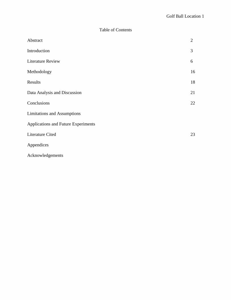
In order to make the game more interesting, obstacles and hazards are placed in various
locations. The Official Rules of Golf state that a hazard is either water or a bunker, a sand trap in
the ground. Trees and thick grass called rough are considered hazards by some people as well.
The ball does not need to be directly on an obstacle to be considered in it. For example, the area
around water is marked with flags, which indicate the land surrounding it within is a threat
(Kelley, 2012). Figure 1 shows a typical golf course, with hazards surrounding it.
Figure 1.Golf course layout. Most golf courses comprise a landscape with trees, bunkers, and
water (“TCU golf clubs”, n.d.).
Long grass
called rough
(dark green) Trees
Short grass called
the fairway (light
green) Sand traps called
bunkers (white)
Out of bounds
(brown) Water
Golf Ball Location 3
Golf Ball Retrieval
Hence a need has become obvious for retrieving golf balls. Some people walk to them,
while others with special licenses can pay to ride in a golf cart (“New rules for golf carts”, 2012).
Locating the golf ball is not always straightforward. If the ball were hit in a patch of long grass,
especially at a far distance, then it would be challenging to locate it. In any case where the ball
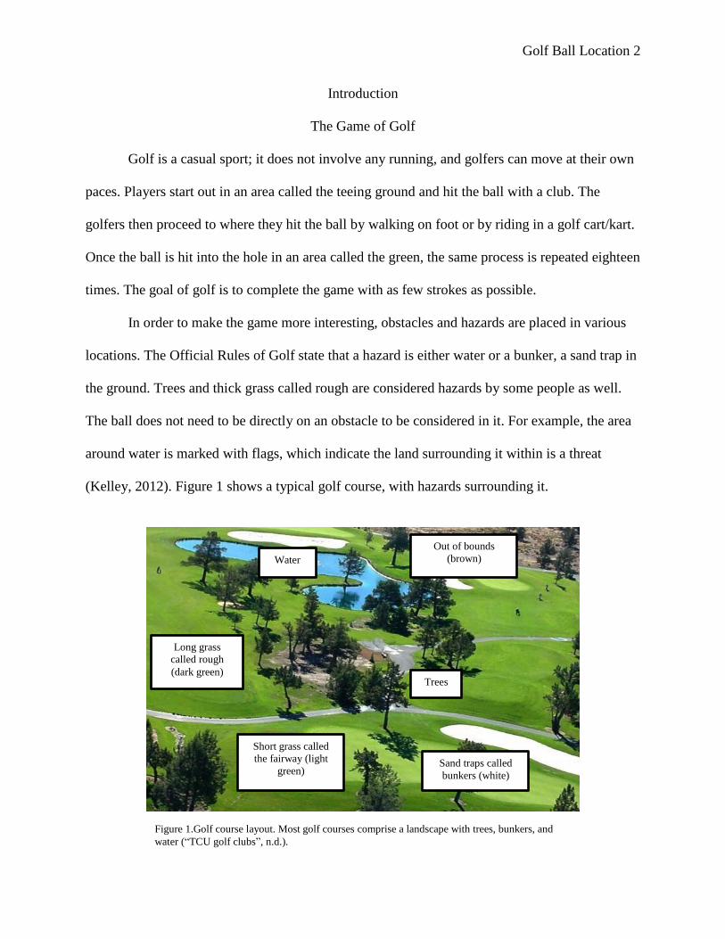
cannot be retrieved, substitute golf balls with identification markers may be used. Even though
golf balls may come in different colors, they all share the same basic design, as shown in Figure
2.
Past Golf Ball Detectors
Recently, golfers have expressed an interest in locating golf balls by using detectors. The
cost per detector ranges depending on what materials the devices comprise.
There are several different kinds of golf ball detectors, and each uses a unique way to
find the ball. One method involves photo imaging, which can only detect white balls. The ball
needs to be at least 1% visible and within 10.7 meters of the device.
Figure 2.Golf ball design. All golf balls have a core that is
surrounded by a shell (“Wilson FG tour & C:25 golf balls”,
n.d.).
Shell (white)
Core (orange)
Golf Ball Location 4
The handheld device called the Ballfinder Scout scans the surrounding area using a
digital imaging system. When the ball is found, the Ballfinder Scout buzzes and an LED light is
targeted towards the ball.
A third example is the Visiball ball finder, which is in the form of eye spectacles. It
absorbs as much light as it can, but allows light to reflect off the ball. As a result, the ball will
appear to be much brighter than its surroundings. Adaptions have been made for people that
actually wear prescription glasses. The Visiball ball finder is less expensive to manufacture than
the Ballfinder Scout (Bodamer, n.d.).
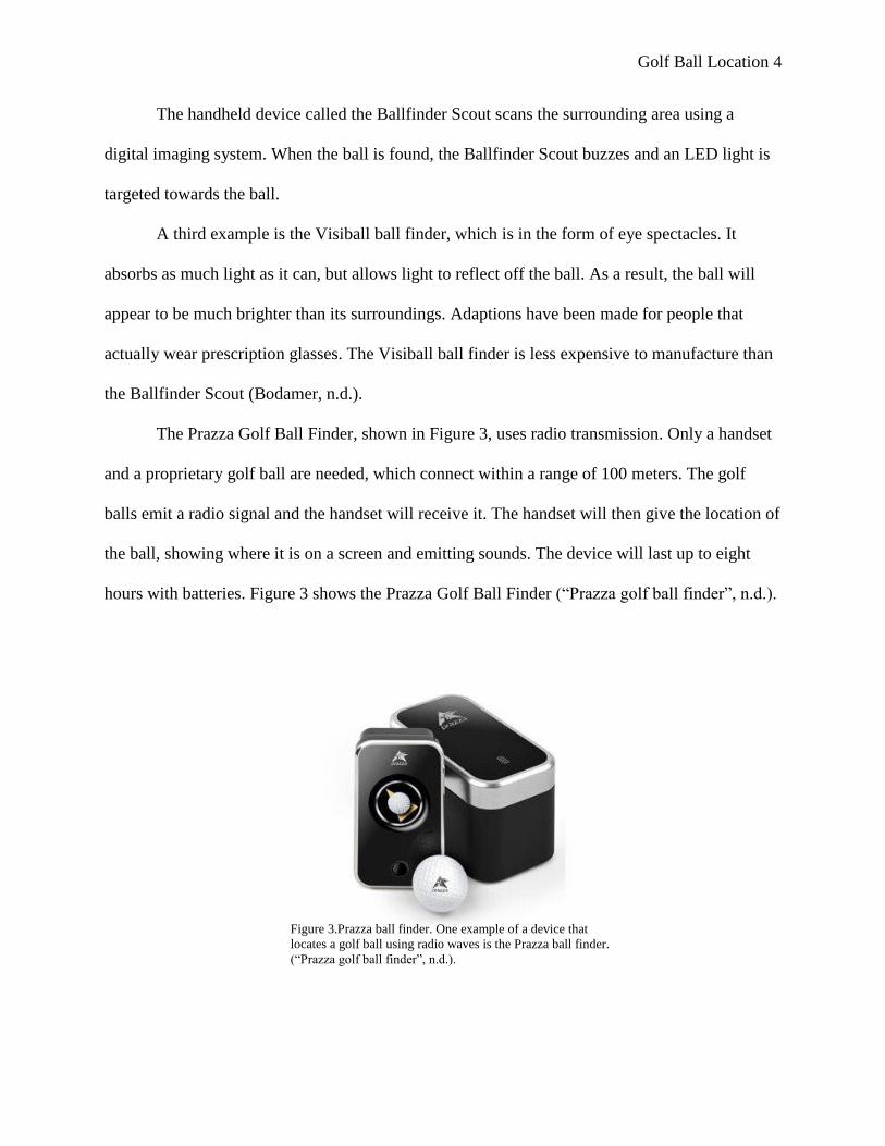
The Prazza Golf Ball Finder, shown in Figure 3, uses radio transmission. Only a handset
and a proprietary golf ball are needed, which connect within a range of 100 meters. The golf
balls emit a radio signal and the handset will receive it. The handset will then give the location of
the ball, showing where it is on a screen and emitting sounds. The device will last up to eight
hours with batteries. Figure 3 shows the Prazza Golf Ball Finder (“Prazza golf ball finder”, n.d.).
Figure 3.Prazza ball finder. One example of a device that
locates a golf ball using radio waves is the Prazza ball finder.
(“Prazza golf ball finder”, n.d.).
Golf Ball Location 5
The idea of light detecting and ranging was considered on a few occasions. LIDAR
detectors search for infrared laser pulses. Because of the thinness in the laser, LIDAR detectors
are less accurate than other golf ball location devices (“How do laser detectors work?”, 2004).
Various applications that use GPS technology are increasing. There exist golf balls that
have a GPS system already built into them, which lets the app user know the exact location of
the ball. At least one golf-related project has been completed using GPS. Chris Savarese devised
RadarGolf, a locating system for golf balls. Proprietary balls are installed with a microchip. A
locating handheld uses GPS technology and will sync to the chip. Within a range of 9.14 to 30.5
meters, the handheld will emit sounds as it navigates closer to the golf ball (Grass, 2011).
Golf Ball Location 6
Literature Review
Circuit Boards
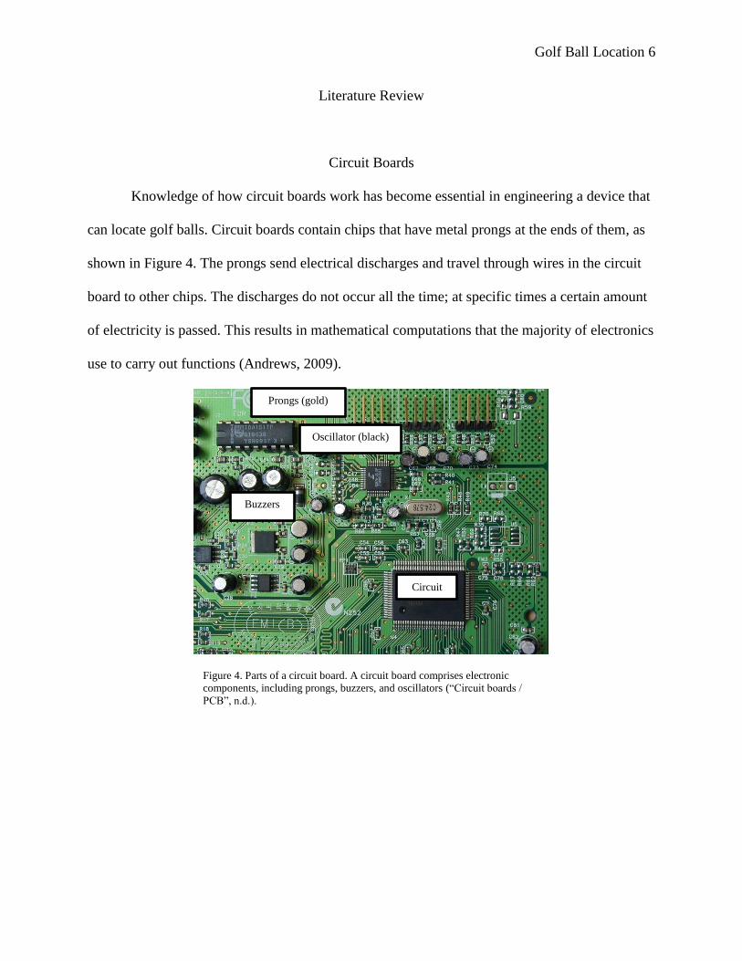
Knowledge of how circuit boards work has become essential in engineering a device that
can locate golf balls. Circuit boards contain chips that have metal prongs at the ends of them, as
shown in Figure 4. The prongs send electrical discharges and travel through wires in the circuit
board to other chips. The discharges do not occur all the time; at specific times a certain amount
of electricity is passed. This results in mathematical computations that the majority of electronics
use to carry out functions (Andrews, 2009).
Figure 4. Parts of a circuit board. A circuit board comprises electronic
components, including prongs, buzzers, and oscillators (“Circuit boards /
PCB”, n.d.).
Prongs (gold)
Oscillator (black)
Circuit
Buzzers
Golf Ball Location 7
Radio Transmitters
Progress in the area of manufacturing radio transmitters has created a surge in locating
lost apparatus. Wireless instrument networks have been used for several years, being used only
by the military when they first came out.
When wireless networks are set up, the type of transmission frequency needs to be
decided, either licensed or unlicensed, From the U.S. Federal Communications Commissions, the
licensed require an application procedure. The unlicensed have limits on the transmission of the
highest power (Eren, 2006).
Radio transmitters are reliable and cost friendly, opening up even more possibilities.
Several devices use them, ranging from microwaves to clocks. Even GPS technology uses radio
waves to a certain extent; they transmit data to the satellites and the satellites return it. The
technology is simple to set up (Brain, n.d.).
GPS Technology
Recent progression in science regarding global positioning systems has enabled its usage
in navigation. When GPS first came out, it was rare and expensive. Ever since it has become one
of the most widely used navigation apparatuses, the cost has been lowered. GPS works by having
satellites orbiting the Earth send signals to a GPS receiver, which will return the signal. The
United States relies on the satellite called Navstar. Other countries use different satellites because
of their location. All of them orbit the Earth every twelve hours and operate at all times. 24 are in
use at a time, and are 18,507.5 kilometers above Earth.
The signals contain information about the location and what time it is. All GPS devices
transmit their data at the same time. The devices are accurate, and most will send the user within
Golf Ball Location 8
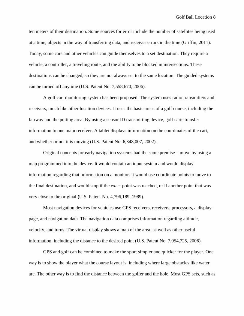
ten meters of their destination. Some sources for error include the number of satellites being used
at a time, objects in the way of transferring data, and receiver errors in the time (Griffin, 2011).
Today, some cars and other vehicles can guide themselves to a set destination. They require a
vehicle, a controller, a traveling route, and the ability to be blocked in intersections. These
destinations can be changed, so they are not always set to the same location. The guided systems
can be turned off anytime (U.S. Patent No. 7,558,670, 2006).
A golf cart monitoring system has been proposed. The system uses radio transmitters and
receivers, much like other location devices. It uses the basic areas of a golf course, including the
fairway and the putting area. By using a sensor ID transmitting device, golf carts transfer
information to one main receiver. A tablet displays information on the coordinates of the cart,
and whether or not it is moving (U.S. Patent No. 6,348,007, 2002).
Original concepts for early navigation systems had the same premise – move by using a
map programmed into the device. It would contain an input system and would display
information regarding that information on a monitor. It would use coordinate points to move to
the final destination, and would stop if the exact point was reached, or if another point that was
very close to the original (U.S. Patent No. 4,796,189, 1989).
Most navigation devices for vehicles use GPS receivers, receivers, processors, a display
page, and navigation data. The navigation data comprises information regarding altitude,
velocity, and turns. The virtual display shows a map of the area, as well as other useful
information, including the distance to the desired point (U.S. Patent No. 7,054,725, 2006).
GPS and golf can be combined to make the sport simpler and quicker for the player. One
way is to show the player what the course layout is, including where large obstacles like water
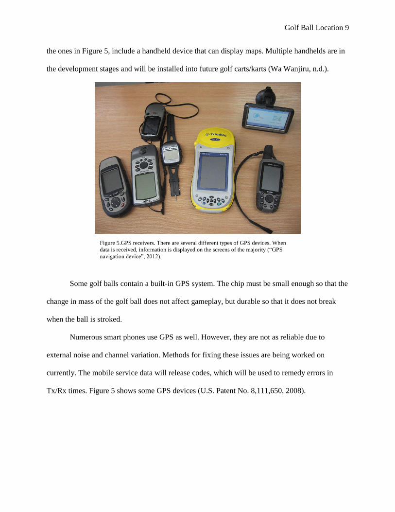
are. The other way is to find the distance between the golfer and the hole. Most GPS sets, such as
Golf Ball Location 9
the ones in Figure 5, include a handheld device that can display maps. Multiple handhelds are in
the development stages and will be installed into future golf carts/karts (Wa Wanjiru, n.d.).
Some golf balls contain a built-in GPS system. The chip must be small enough so that the
change in mass of the golf ball does not affect gameplay, but durable so that it does not break
when the ball is stroked.
Numerous smart phones use GPS as well. However, they are not as reliable due to
external noise and channel variation. Methods for fixing these issues are being worked on
currently. The mobile service data will release codes, which will be used to remedy errors in
Tx/Rx times. Figure 5 shows some GPS devices (U.S. Patent No. 8,111,650, 2008).
Figure 5.GPS receivers. There are several different types of GPS devices. When
data is received, information is displayed on the screens of the majority (“GPS
navigation device”, 2012).
Golf Ball Location 10
Bluetooth
Knowledge of Bluetooth technology has become essential in syncing new golf balls to
the location devices. The purpose of Bluetooth is to perform technological tasks wirelessly, using
one core system. The physical layer of a Bluetooth device uses a band that runs on 2.4 gigahertz,
the same frequency Wi-Fi uses. It is managed with an RF topology allegedly called “star
topology.”
When groups of devices are synced to the same frequency-hopping and clock patterns,
radio stations can be shared. There is a principal device that is the basis for synchronization. For
example, a smart phone could be the basis, while a GPS receiver and a car stereo are other
devices in the group. Frequency-hopping patterns can use frequencies of intrusive mechanisms.
The wireless channels are divided into time slots, where data is transferred. At this
moment, frequency-hopping takes place. The channels carry links for all types of data, ranging
from audio files to calendars (Scientific american, 2007).
The principal device relies on signals from other devices to be able to connect. Once the
signal has been received, a response will be sent from the main device to the other ones, allowing
them to interact.
Engineering Plan
Researchable question or engineering problem being addressed:
Golf balls can be difficult to locate after they are driven by golfers, especially when they land at
a far distance.
Golf Ball Location 11
Engineering Goal:
The goal of this project is to build a location device to automatically locate the golf ball.
Description in detail of methods or procedures:
People can locate roughly anything by using sonar, radar, tagging, quantum dots, GPS,
and radio transmission. Sonar is when objects emit a sound wave and the wave is reflected back
at them, producing an echo. Sonar can travel for thousands of miles. Depending on the frequency
of the echo, that is how animals know how big an organism or area is. Several animals with poor
eyesight use it, especially underwater. Bats, dolphins, and whales are among them.
In radar, signals are sent between three radar installations, where they will ping in a
triangular method. For example, in the golf project, the locations could be a tower, the ball, and
the location handheld.
When animals become tagged, scientists can locate them at any given moment. Satellite
tagging is used for mostly large animals. The purpose is so that scientists can research their
migration patterns and movements. The process occurs between a satellite and a receiver. Data
transmitted includes latitude, longitude, date, and time. This type of tagging is very expensive, at
approximately $3,500 per tag. Two types of satellite tagging exist for marine organisms. One is
instantaneous, and the other is when the organism surfaces. Archival tags are used to find out the
living conditions of an animal, including their body temperature, heart rate, and light
surroundings. Scientists study this so that they can find out how an organism reacts to changes in
their environment. There is no way to transmit the data, so scientists must manually retrieve the
tags (Goetz, 2012).
Golf Ball Location 12
Quantum dots, or semiconductor nanocrystals, are micro-sized molecules that contain
electrons. The number of electrons in a quantum dot varies from one to several thousand, where
their dimensions and amount can be controlled. Depending on these changes, energy levels can
change significantly. When connected to electrodes, they can be used to study atomic properties.
Quantum dots are the result of when thin semiconductor films bend due to the difference in
lattice structures that the films were originally formed. They are used in abundant electrical
devices, including semiconductors for cascade lasers, injection lasers, quantum computers,
semiconductors for photo detectors, and places for storing information (Mishra, n.d.). They can
also be used for DNA testing, and rendering 3D models inside an organism. Quantum dots are
valuable when it comes to methods of locations. When the semiconductors change, they emit
unique colors. The colors can be used like a barcode in a super market, where each code is
unique. They can be injected into components of the human body, like proteins and cells, to
locate biomolecules (“Quantum dots - what are quantum dots, why are they important and what
applications are they used in?”, 2005). Quantum dots are not widely used because they are
relatively new and are expensive. In the future, however, they may be used on currency so that
counterfeit money will become obsolete. Quantum dots would not be a good option for golf ball
location, as the price to manufacture golf balls with them would be high.
Golf Ball Location 13
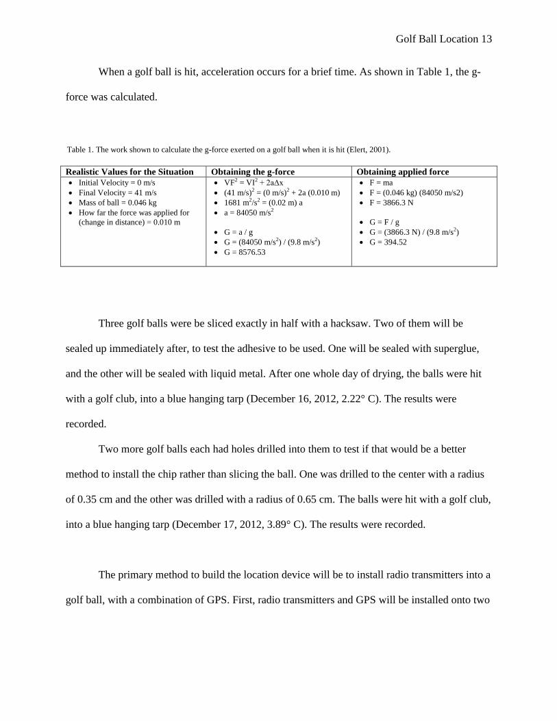
When a golf ball is hit, acceleration occurs for a brief time. As shown in Table 1, the g-
force was calculated.
Realistic Values for the Situation Obtaining the g-force Obtaining applied force
Initial Velocity = 0 m/s
Final Velocity = 41 m/s
Mass of ball = 0.046 kg
How far the force was applied for
(change in distance) = 0.010 m
VF2 = VI2 + 2aΔx
(41 m/s)2 = (0 m/s)2 + 2a (0.010 m)
1681 m2/s2 = (0.02 m) a
a = 84050 m/s2
G = a / g
G = (84050 m/s2) / (9.8 m/s2)
G = 8576.53
F = ma
F = (0.046 kg) (84050 m/s2)
F = 3866.3 N
G = F / g
G = (3866.3 N) / (9.8 m/s2)
G = 394.52
Three golf balls were be sliced exactly in half with a hacksaw. Two of them will be
sealed up immediately after, to test the adhesive to be used. One will be sealed with superglue,
and the other will be sealed with liquid metal. After one whole day of drying, the balls were hit
with a golf club, into a blue hanging tarp (December 16, 2012, 2.22° C). The results were
recorded.
Two more golf balls each had holes drilled into them to test if that would be a better
method to install the chip rather than slicing the ball. One was drilled to the center with a radius
of 0.35 cm and the other was drilled with a radius of 0.65 cm. The balls were hit with a golf club,
into a blue hanging tarp (December 17, 2012, 3.89° C). The results were recorded.
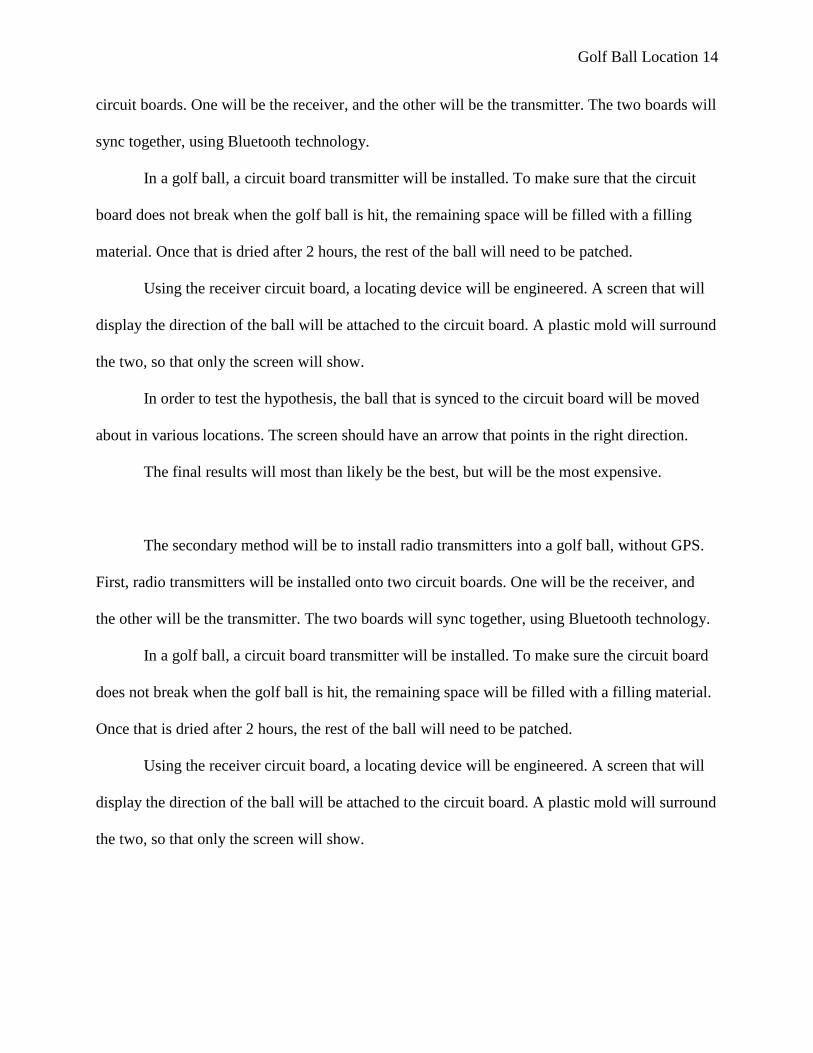
The primary method to build the location device will be to install radio transmitters into a
golf ball, with a combination of GPS. First, radio transmitters and GPS will be installed onto two
Table 1. The work shown to calculate the g-force exerted on a golf ball when it is hit (Elert, 2001).
Golf Ball Location 14
circuit boards. One will be the receiver, and the other will be the transmitter. The two boards will
sync together, using Bluetooth technology.
In a golf ball, a circuit board transmitter will be installed. To make sure that the circuit
board does not break when the golf ball is hit, the remaining space will be filled with a filling
material. Once that is dried after 2 hours, the rest of the ball will need to be patched.
Using the receiver circuit board, a locating device will be engineered. A screen that will
display the direction of the ball will be attached to the circuit board. A plastic mold will surround
the two, so that only the screen will show.
In order to test the hypothesis, the ball that is synced to the circuit board will be moved
about in various locations. The screen should have an arrow that points in the right direction.
The final results will most than likely be the best, but will be the most expensive.
The secondary method will be to install radio transmitters into a golf ball, without GPS.
First, radio transmitters will be installed onto two circuit boards. One will be the receiver, and
the other will be the transmitter. The two boards will sync together, using Bluetooth technology.
In a golf ball, a circuit board transmitter will be installed. To make sure the circuit board
does not break when the golf ball is hit, the remaining space will be filled with a filling material.
Once that is dried after 2 hours, the rest of the ball will need to be patched.
Using the receiver circuit board, a locating device will be engineered. A screen that will
display the direction of the ball will be attached to the circuit board. A plastic mold will surround
the two, so that only the screen will show.
Golf Ball Location 15
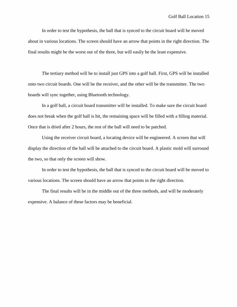
In order to test the hypothesis, the ball that is synced to the circuit board will be moved
about in various locations. The screen should have an arrow that points in the right direction. The
final results might be the worst out of the three, but will easily be the least expensive.
The tertiary method will be to install just GPS into a golf ball. First, GPS will be installed
onto two circuit boards. One will be the receiver, and the other will be the transmitter. The two
boards will sync together, using Bluetooth technology.
In a golf ball, a circuit board transmitter will be installed. To make sure the circuit board
does not break when the golf ball is hit, the remaining space will be filled with a filling material.
Once that is dried after 2 hours, the rest of the ball will need to be patched.
Using the receiver circuit board, a locating device will be engineered. A screen that will
display the direction of the ball will be attached to the circuit board. A plastic mold will surround
the two, so that only the screen will show.
In order to test the hypothesis, the ball that is synced to the circuit board will be moved to
various locations. The screen should have an arrow that points in the right direction.
The final results will be in the middle out of the three methods, and will be moderately
expensive. A balance of these factors may be beneficial.
Golf Ball Location 16
Methodology
Two circuit boards (BRAND, DIMENSIONS, WEIGHT) will have one GPS transmitter
(BRAND, SIZE OF CHIP, WEIGHT, POSSIBLE RANGE) and one radio transmitter (BRAND,
SIZE, WEIGHT, POSSIBLE RANGE) installed and soldered onto each of them. The devices
will be synced together.
Three golf balls (Wilson brand, weight of 46 g, diameter of 42.7 mm, inner core made out
of black proprietary material, diameter of 3.81 cm, volume of 28.94 cubic cm, outer shell made
out of white thermoplastic) were cut exactly in half using a vice and a hacksaw (basement of the
student). One of the balls was super-glued back together (Gorilla Brand, enough to cover 11.395
square cm), while a second one was sealed using liquid metal. After drying for two hours, both
of them were taken outside (December 17, 2012, 3.89° C). A tarp was hung on a soccer net, so
that the tarp was perpendicular to the ground beneath it. Both of the balls were hit by a golf club
(Spalding brand, DIMENSIONS) into the tarp from a distance of 0.5 meters. The purpose was to
test which adhesive would be better to use, and the results were recorded.
In the third golf ball, exactly ___ ounces of the core was cut out, and one of the circuit
boards was put in the hole. A filling material called ___ (MATERIALS, HOW MUCH,
WEIGHT, COLOR) was put around the chip on the half of the golf ball, making that side as flat
as it was originally. It took ___ minutes for the sealer to dry. After, the two halves of the golf
ball were fastened back together using ___ (BRAND, MATERIALS, HOW MUCH, WEIGHT,
COLOR).
With the other circuit board, a location device was engineered. A screen (BRAND,
WEIGHT, DIMENSIONS) was placed parallel to the circuit board. The two were connected by

Golf Ball Location 17
___. The circuit board and the screen were fastened to a plastic mold (BRAND, COLOR,
DIMENSIONS, WEIGHT).
Last, the golf ball with the circuit board will be placed in various locations, and the
device will be tested.
Golf Ball Location 18
Results
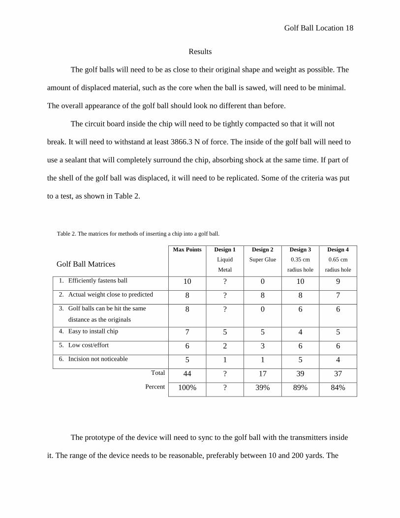
The golf balls will need to be as close to their original shape and weight as possible. The
amount of displaced material, such as the core when the ball is sawed, will need to be minimal.
The overall appearance of the golf ball should look no different than before.
The circuit board inside the chip will need to be tightly compacted so that it will not
break. It will need to withstand at least 3866.3 N of force. The inside of the golf ball will need to
use a sealant that will completely surround the chip, absorbing shock at the same time. If part of
the shell of the golf ball was displaced, it will need to be replicated. Some of the criteria was put
to a test, as shown in Table 2.
Golf Ball Matrices
Max Points Design 1
Liquid
Metal
Design 2
Super Glue
Design 3
0.35 cm
radius hole
Design 4
0.65 cm
radius hole
1. Efficiently fastens ball 10 ? 0 10 9
2. Actual weight close to predicted 8 ? 8 8 7
3. Golf balls can be hit the same
distance as the originals
8 ? 0 6 6
4. Easy to install chip 7 5 5 4 5
5. Low cost/effort 6 2 3 6 6
6. Incision not noticeable 5 1 1 5 4
Total 44 ? 17 39 37
Percent 100% ? 39% 89% 84%
The prototype of the device will need to sync to the golf ball with the transmitters inside
it. The range of the device needs to be reasonable, preferably between 10 and 200 yards. The
Table 2. The matrices for methods of inserting a chip into a golf ball.
Golf Ball Location 19
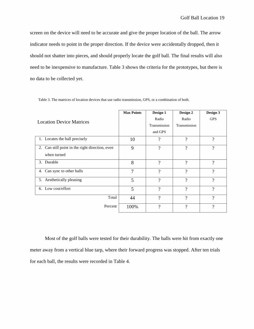
screen on the device will need to be accurate and give the proper location of the ball. The arrow
indicator needs to point in the proper direction. If the device were accidentally dropped, then it
should not shatter into pieces, and should properly locate the golf ball. The final results will also
need to be inexpensive to manufacture. Table 3 shows the criteria for the prototypes, but there is
no data to be collected yet.
Location Device Matrices
Max Points Design 1
Radio
Transmission
and GPS
Design 2
Radio
Transmission
Design 3
GPS
1. Locates the ball precisely 10 ? ? ?
2. Can still point in the right direction, even
when turned
9 ? ? ?
3. Durable 8 ? ? ?
4. Can sync to other balls 7 ? ? ?
5. Aesthetically pleasing 5 ? ? ?
6. Low cost/effort 5 ? ? ?
Total 44 ? ? ?
Percent 100% ? ? ?
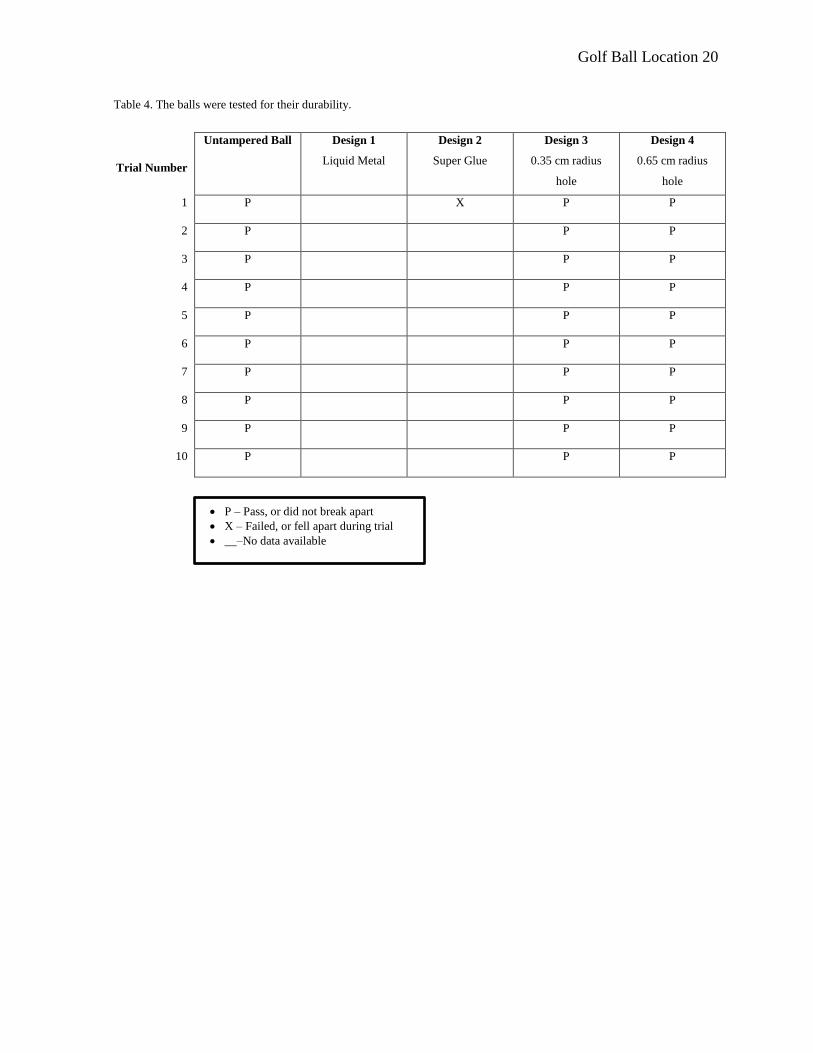
Most of the golf balls were tested for their durability. The balls were hit from exactly one
meter away from a vertical blue tarp, where their forward progress was stopped. After ten trials
for each ball, the results were recorded in Table 4.
Table 3. The matrices of location devices that use radio transmission, GPS, or a combination of both.
Golf Ball Location 20
Trial Number
Untampered Ball Design 1
Liquid Metal
Design 2
Super Glue
Design 3
0.35 cm radius
hole
Design 4
0.65 cm radius
hole
1 P X P P
2 P P P
3 P P P
4 P P P
5 P P P
6 P P P
7 P P P
8 P P P
9 P P P
10 P P P
Table 4. The balls were tested for their durability.
P – Pass, or did not break apart
X – Failed, or fell apart during trial
__–No data available
Golf Ball Location 21
Data Analysis and Discussion
As a result from the data in Table 4, golf balls with holes drilled to the core will be the
ideal solution to get the chip into the ball. The superglue ball broke apart on the first stroke,
eliminating that possible solution. The smaller hole will be the least noticeable, but if the chip is
too big to fit inside it, then it will not work. The larger hole can fit the chip, but will require more
time and effort to seal.
There are many possible sources of error. If the balls were not filled with proper
materials, the chip inside could break. If the filling materials caused the ball to have a different
mass, density, or volume than it originally did, there could be an overall effect on gameplay.
There are many different brands of golf balls. If one of the older styles were used that contained
a rubber ball inside the core, then the chip could break more easily.
If the location device could not be synced to the golf ball, and Bluetooth was not
working properly, then the receiver would be pointless. The coordinates that the device receives
could be wrong, and then the screen could point in the opposite direction of the ball. If the device
were dropped, then the receiving chip inside could become separated from the wires, and the
device would not work.
The amount of g-force calculated could be off a little, so if it were slightly greater than it
was actually, then there could be potential danger for the chip.

Golf Ball Location 22
Conclusion
There was insufficient amount of data to reach a conclusion.
Golf Ball Location 23
Literature Cited
Akiba, N., Kawasaki, H., and Yoshino, H. (2002, February 19). U.S. Patent No. 6,348,007.
Washington D.C.: U.S. Patent and Trademark Office.
Andrews, D. (2009, March 10). Computer Tech Support : How Do Circuit Boards Work?
Retrieved from http://www.youtube.com/watch?v=gUzyd4klMQk
Atsuo, N. (2006). U.S. Patent No. 7,558,670. Washington D.C.: U.S. Patent and Trademark
Office.
Bodamer, T. (2012). Golf ball finders: How they work. Retrieved from
http://golftips.golfsmith.com/golf-ball-finders-work-1445.html
Brain, Marshall. (n.d.). How radio works. Retrieved from http://electronics.howstuffworks.com/
Brown, D., Burch, M., Krull, J., and Pemble, C. (2006, May 30). U.S. Patent No. 7,054,725.
Washington D.C.: U.S. Patent and Trademark Office.
Cho, E., Choi, I., Lee, H., Kim, B., Kim, J.M., Kim, J.W., Kwak, K., and Song, W. (2008, April
14). U.S. Patent No. 8,111,650.Washington D.C.: U.S. Patent and Trademark Office.
Circuit boards / PCB. (n.d.). Retrieved from
http://www.reatechnologies.com/circuitbrd.html
Elert, G. (2001). Force of a golf club on a golf ball. Retrieved from
http://hypertextbook.com/facts/2001/EmilyAccamando.shtml
Eren, H. (2006). Wireless sensors and instruments: Networks, design, and applications. Boca
Raton, FL: CRC Press.
Goetz, K., Kerkering, H., Sanderson, M., and Stovall, J. (2012, June 22). Lesson: Marine animal
tracking. Retrieved from http://www.teachengineering.org/
GPS navigation device. (2012). Retrieved from
http://en.wikipedia.org/wiki/GPS_navigation_device
Grass, Jennifer. (2011). Golf ball GPS. Retrieved from
http://www.radargolf.com/news/articles/072007.asp
Griffin, D. (2011, June). How does the global positioning system work?. Retrieved from
http://www.pocketgpsworld.com/howgpsworks.php
Itoh, T., Nakayama, O., and Ueno, H. (1989, January 3). U.S. Patent No. 4,796,189. Washington
D.C.: U.S. Patent and Trademark Office.
Golf Ball Location 24
Kagawa, K. (1998, November 10). U.S. Patent No. 5,835,870. Washington D.C.: U.S. Patent and
Trademark Office.
Kelley, B. (2012). Hazard. Retrieved from
http://golf.about.com/od/golfterms/g/Hazard.htm
Lowe, D. (2011, 10 July). Electronics projects: How to use comments in PBASIC code.
Retrieved from http://www.dummies.com
Mishra, G. (n.d.). Quantum Dots. Retrieved from
http://wolfweb.unr.edu/homepage/bruch/Phys461/6.pdf
New rules for golf carts. (2012, June 26). Retrieved from
http://www.cityoffollybeach.com/new-rules-for-golf-carts/
Niibe, T., Uemura, H., and Yoshioka, T. (1993, January 28). U.S. Patent No.
5,332,056.Washington D.C.: U.S. Patent and Trademark Office.
Obstacle sensing apparatus for vehicles. (1995, December 26). U.S. Patent No. 5,479,173.
Washington D.C.: U.S. Patent and Trademark Office.
PBASIC language. (n.d.). Retrieved from http://uttermatter.com/bs2/S_PBASIC.php
Prazza golf ball finder. (n.d.). Retrieved from http://www.amazon.com
Quantum dots - what are quantum dots, why are they important and what applications are they
used in? (2005, August 25). Retrieved from http://www.azonano.com/
Re: MG tour C-4. (2010, 27 July). [Picture of golf ball cut in half]. Retrieved from
http://www.golfwrx.com/forums/topic/294661-mg-tour-c-4/page__st__30
Reply 1: How does a laser detector work? (2004, March 9). [Comment on how a laser detector
works]. Retrieved from
http://www.airliners.net/aviation-forums/non_aviation/read.main/516608/
Scientific American. (2007). How does bluetooth work?. Retrieved from
http://www.scientificamerican.com/
WaWanjiru, M. (n.d.). GPS golf; How can a GPS system work with the game of golf? Retrieved
from http://www.streetdirectory.com/travel_guide/115686/gaming/
gps_golf_how_can_a_gps_system_work_with_the_game_of_golf.html
Wilson FG tour & C:25 golf balls. (n.d.). Retrieved from
http://linksnation.com/site/index.php?option=com_content&view=article&id=
117:wilson-fg-tour-a-c25-golf-balls&catid=8:golf-equip